1957 chevrolet belair tech column install how to · classic performance products | 714.522.2000 |...
TRANSCRIPT
Classic Performance Products | 714.522.2000 | 175 E. Freedom Avenue | Anaheim, CA 92801 | www.classicperform.com
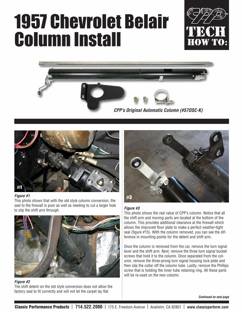
HOW TO:TECH1957 Chevrolet Belair
Column Install
Continued on next page
Figure #1This photo shows that with the old style column conversion, the seal to the firewall is poor as well as needing to cut a larger hole to slip the shift arm through.
Figure #2The shift detent on the old style conversion does not allow the factory seal to fit correctly and will not let the carpet lay flat.
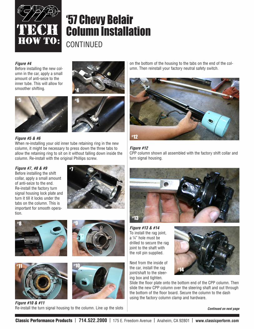
Figure #3 This photo shows the real value of CPP’s column. Notice that all the shift arm and moving parts are located at the bottom of the column. This provides additional clearance at the firewall which allows the improved floor plate to make a perfect weather-tight seal (figure #15). With the column removed, you can see the dif-ference in mounting points for the detent and shift arm.
Once the column is removed from the car, remove the turn signal lever and the shift arm. Next, remove the three turn signal bucket screws that hold it to the column. Once separated from the col-umn, remove the three-prong turn signal housing lock plate and then slip the collar off the column tube. Lastly, remove the Phillips screw that is holding the inner tube retaining ring. All these parts will be re-used on the new column.
CPP’s Original Automatic Column (#57OSC-K)
#1
#2
#3
Classic Performance Products | 714.522.2000 | 175 E. Freedom Avenue | Anaheim, CA 92801 | www.classicperform.com Classic Performance Products | 714.522.2000 | 175 E. Freedom Avenue | Anaheim, CA 92801 | www.classicperform.com
HOW TO:TECH
‘57 Chevy Belair Column InstallationCONTINUED
Continued on next page
Figure #4 Before installing the new col-umn in the car, apply a small amount of anti-seize to the inner tube. This will allow for smoother shifting.
Figure #5 & #6 When re-installing your old inner tube retaining ring in the new column, it might be necessary to press down the three tabs to allow the retaining ring to sit on it without falling down inside the column. Re-install with the original Phillips screw.
Figure #7, #8 & #9Before installing the shift collar, apply a small amount of anti-seize to the end. Re-install the factory turn signal housing lock plate and turn it till it locks under the tabs on the column. This is important for smooth opera-tion.
Figure #10 & #11Re-install the turn signal housing to the column. Line up the slots
on the bottom of the housing to the tabs on the end of the col-umn. Then reinstall your factory neutral safety switch.
Figure #12 CPP column shown all assembled with the factory shift collar and turn signal housing.
Figure #13 & #14To install the rag joint, a ¼” hole must be drilled to secure the rag joint to the shaft with the roll pin supplied.
Next from the inside of the car, install the rag joint/shaft to the steer-ing box and tighten. Slide the floor plate onto the bottom end of the CPP column. Then slide the new CPP column over the steering shaft and out through the bottom of the floor board. Secure the column to the dash using the factory column clamp and hardware.
#5 #6
#7
#8 #9
#10#11
#12
#13
#14
#4
Classic Performance Products | 714.522.2000 | 175 E. Freedom Avenue | Anaheim, CA 92801 | www.classicperform.com Classic Performance Products | 714.522.2000 | 175 E. Freedom Avenue | Anaheim, CA 92801 | www.classicperform.com
© Copyright Classic Performance Products, Inc. 2009. All Rights Re-served. This article, in whole or in part, may not be reproduced, stored in a computerized, or other retrieval system or transmitted in any form, or by any means whatsoever without the prior written permis-sion of Classic Performance Products, Inc.
HOW TO:TECH
‘57 Chevy Belair Column InstallationCONTINUED
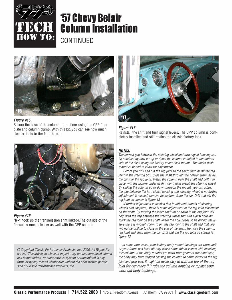
Figure #15Secure the base of the column to the floor using the CPP floor plate and column clamp. With this kit, you can see how much cleaner it fits to the floor board.
Figure #16Next hook up the transmission shift linkage.The outside of the firewall is much cleaner as well with the CPP column.
Figure #17 Reinstall the shift and turn signal levers. The CPP column is com-pletely installed and still retains the classic factory look.
NOTES:The correct gap between the steering wheel and turn signal housing can be obtained by how far up or down the column is bolted to the bottom side of the dash using the factory under dash mount. The under dash mount is slotted to allow for adjustment. Before you drill and pin the rag joint to the shaft, first install the rag joint to the steering box. Slide the shaft through the firewall from inside the car into the rag joint. Install the column over the shaft and bolt it in place with the factory under dash mount. Now install the steering wheel. By sliding the column up or down through the mount, you can adjust the gap between the turn signal housing and steering wheel. If no further adjustment is needed, remove the column from the car. Drill and pin the rag joint as shown is figure 13. If further adjustment is needed due to different brands of steering wheels and adapters, there is some adjustment in the rag joint placement on the shaft. By moving the inner shaft up or down in the rag joint will help with the gap between the steering wheel and turn signal housing. Mark the rag joint on the shaft where the hole needs to be drilled. Make sure there is enough room to pin the rag joint to the shaft and that you will not be drilling to close to the end of the shaft. Remove the column, rag joint and shaft from the car. Drill and pin the rag joint as shown is figure 13.
In some rare cases, your factory body mount bushings are worn and/or your frame has been hit may cause some minor issues with installing this column. If the body mounts are worn from years of wear and tear, the body may have sagged causing the column to come closer to the rag joint and gear box. It might be necessary to trim the top of the rag joint for clearance if it rubs the column housing or replace your worn out body bushings.
#15
#16
#17