1955-1956 chevy bel-era - classic instruments chevy... · 1955-1956 chevy . bel-era . installation...
TRANSCRIPT

Revised January 2, 2014 Page 1
Classic Instruments
1955-1956 Chevy Bel-Era
Installation Manual
Revised January 2, 2014 Page 2
Table of Contents
Table of Contents ________________________________________ 2
Welcome to the Team of Classic Instruments! _________________ 3
’55-’56 Chevy Part Identification ____________________________ 4
Installing Your 1955/56 Classic Gauge Set ____________________ 5 Disassemble the Original Gauge Set ___________________________ 5 Assembling Your New Classic Gauge Set _______________________ 7 1955 / 1956 Chevy Wiring Diagrams _________________________ 10
Using Classic Instruments Pulse Signal Generator _____________________ 10 Using Transmission Vehicle Speed Sensor __________________________ 11 Using ECM Speed Signal ________________________________________ 12
Wiring your 1955 / 56 Chevy Classic Gauge Set _______________ 13 Speedometer, Tachometer, Volt and Oil Pressure Gauge_________ 13 Fuel and Temperature Gauge _______________________________ 16 Gear Selector Gauge _______________________________________ 17
Setting Up Your Speedometer and Tachometer ________________ 18 Entering Setup Mode: _____________________________________ 18 Tachometer Setup: ________________________________________ 19
Cylinder Select: _______________________________________________ 19 Tachometer Signal Type: ________________________________________ 20
Speedometer Setup: _______________________________________ 21 Speed Auto Calibrate: ___________________________________________ 21 Real-Time Speed Adjust: ________________________________________ 22

Revised January 2, 2014 Page 3
Welcome to the Team of Classic Instruments!
Our congratulations and appreciation for your purchase of the finest quality set of specialty instruments ever produced! Your instrument set has been conceived, designed, and manufactured by Classic Instruments, Inc. in the U.S.A. Each instrument has been tested and certified for accuracy and quality before packaging and shipping.
For trouble-free installation and operation, follow the instructions exactly as
outlined. Your instruments were assembled to precise specifications and although each has a five (5) year warranty covering defective parts and workmanship – this warranty will not cover instruments or sending units which have been installed incorrectly.
LIMITED WARRANTY
Classic Instruments, Inc. (CI) warrants to the original purchaser that any CI product
manufactured or supplied by CI will be free from defects in material and workmanship under normal use and service for a period of five (5) years from date of purchase.
Improper installation, use of sending units other than CI’s or attempted repair or
adjustments by other than CI shall void this warranty. Disassembly of any instruments or senders for whatever reason shall specifically void this warranty.
Purchaser requesting a product to be repaired or replaced under warranty must first
call CI at 1-800-575-0461 before the return of defective part. Send defective part either to 826 Moll Drive, through UPS, or to P.O. Box 411 through U.S. Mail, Boyne City, MI 49712, USA. Include a written description of the failure with defective part.
Purchaser agrees and accepts that under no circumstances will a warranty
replacement be furnished until CI has first received, inspected, and tested the returned part. All other warranties expressed or implied are hereby excluded including any implied
warranty of merchandise and implied warranty of fitness for a particular purpose. The sole and exclusive remedy for breach of this warranty is limited to the replacement set forth above.
It is expressly agreed that there shall be no further remedy for consequential or other
type of damage, including any claim for loss of profit, engine damage or injury.
TECHNICAL ASSISTANCE
1-231-582-0461 OR
Visit our new website for the latest in gauge design and updates to our installation manual at:
www.classicinstruments.com
Revised January 2, 2014 Page 4
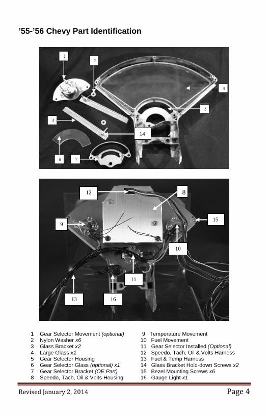
’55-’56 Chevy Part Identification
1 Gear Selector Movement (optional) 9 Temperature Movement 2 Nylon Washer x6 10 Fuel Movement 3 Glass Bracket x2 11 Gear Selector Installed (Optional) 4 Large Glass x1 12 Speedo, Tach, Oil & Volts Harness 5 Gear Selector Housing 13 Fuel & Temp Harness 6 Gear Selector Glass (optional) x1 14 Glass Bracket Hold-down Screws x2 7 Gear Selector Bracket (OE Part) 15 Bezel Mounting Screws x6 8 Speedo, Tach, Oil & Volts Housing 16 Gauge Light x1
9
8
10
11
12
13
14
15
16
Revised January 2, 2014 Page 5
Installing Your 1955/56 Classic Gauge Set
Disassemble the Original Gauge Set
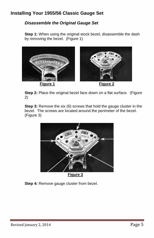
Step 1: When using the original stock bezel, disassemble the dash by removing the bezel. (Figure 1)
Figure 1 Figure 2 Step 2: Place the original bezel face down on a flat surface. (Figure 2) Step 3: Remove the six (6) screws that hold the gauge cluster in the bezel. The screws are located around the perimeter of the bezel. (Figure 3)
Figure 3
Step 4: Remove gauge cluster from bezel.
Revised January 2, 2014 Page 6
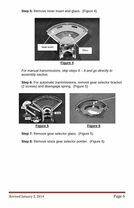
Step 5: Remove inner insert and glass. (Figure 4)
Figure 4
For manual transmissions, skip steps 6 – 8 and go directly to assembly section. Step 6: For automatic transmissions, remove gear selector bracket (2 screws) and disengage spring. (Figure 5)
Figure 5 Figure 6
Step 7: Remove gear selector glass. (Figure 5) Step 8: Remove stock gear selector pointer. (Figure 6)
Revised January 2, 2014 Page 7
Assembling Your New Classic Gauge Set
Note: Assembling using after-market bezel may require enlargements of mounting holes.
For manual transmissions, skip steps 1 – 4 & 6
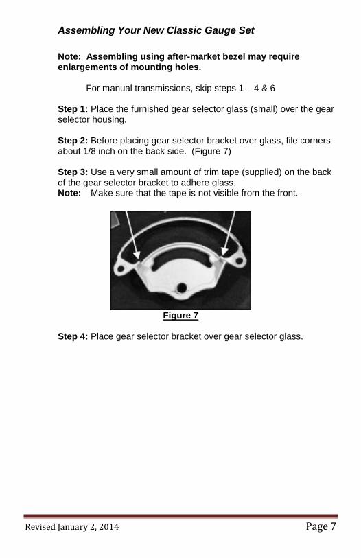
Step 1: Place the furnished gear selector glass (small) over the gear selector housing. Step 2: Before placing gear selector bracket over glass, file corners about 1/8 inch on the back side. (Figure 7) Step 3: Use a very small amount of trim tape (supplied) on the back of the gear selector bracket to adhere glass. Note: Make sure that the tape is not visible from the front.
Figure 7
Step 4: Place gear selector bracket over gear selector glass.
Revised January 2, 2014 Page 8
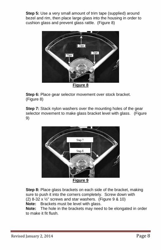
Step 5: Use a very small amount of trim tape (supplied) around bezel and rim, then place large glass into the housing in order to cushion glass and prevent glass rattle. (Figure 8)
Figure 8
Step 6: Place gear selector movement over stock bracket. (Figure 8) Step 7: Stack nylon washers over the mounting holes of the gear selector movement to make glass bracket level with glass. (Figure 9)
Figure 9
Step 8: Place glass brackets on each side of the bracket, making sure to push it into the corners completely. Screw down with (2) 8-32 x ½” screws and star washers. (Figure 9 & 10) Note: Brackets must be level with glass. Note: The hole in the brackets may need to be elongated in order to make it fit flush.
Revised January 2, 2014 Page 9
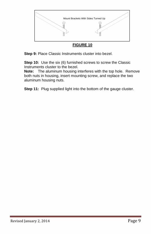
Mount Brackets With Sides Turned Up
FIGURE 10 Step 9: Place Classic Instruments cluster into bezel. Step 10: Use the six (6) furnished screws to screw the Classic Instruments cluster to the bezel. Note: The aluminum housing interferes with the top hole. Remove both nuts in housing, insert mounting screw, and replace the two aluminum housing nuts. Step 11: Plug supplied light into the bottom of the gauge cluster.
Revised January 2, 2014 Page 10
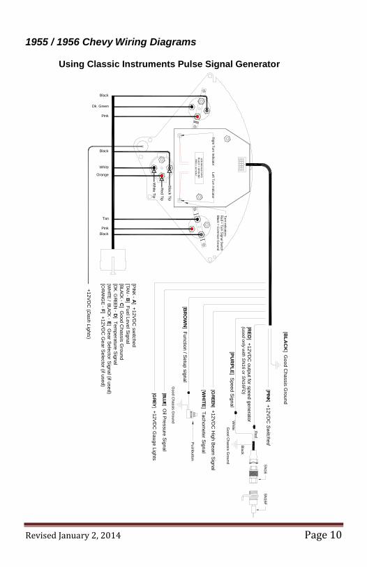
1955 / 1956 Chevy Wiring Diagrams
Using Classic Instruments Pulse Signal Generator
Turn indicators:R
ed = Turn Signal S
witch
Black = C
omm
on Ground
LED
IND
ICA
TOR
SB
LAC
K = G
RO
UN
DR
ED
= 12 VO
LT
Left Turn IndicatorR
ight Turn Indicator
Black
Dk. Green
Pink
Orange
White
Tan
PinkBlack
[PINK - A
] +12VD
C sw
itched[ TAN - B
] Fuel Level Signal
[ BLACK - C] G
ood Chassis G
round[ DK. G
REEN - D] Tem
perature Signal
[WHITE / BLACK - E
] Gear S
elector Signal (if used)
[OR
ANG
E - F] +12VD
C G
ear Selector (if used)
+12VD
C (D
ash Lights)
White Tip
Black Tip
Red Tip
[BLA
CK
] Good C
hassis Ground
[PINK ] +12VD
C S
witched
[RED
] +12VD
C output for speed generator
(used only with S
N16 or S
N16FD
)
Red
White
[PUR
PLE] S
peed Signal
Good C
hassis Ground
Black
[ GREEN
] +12VD
C H
igh Beam
Signal
[WH
ITE] Tachom
eter Signal
[BR
OW
N] Function / S
etup signal
Good C
hassis Ground
SN
16S
N16F
Pushbutton
[BLUE] Oil P
ressure Signal
[GREY
] +12VD
C G
auge Lights
Black
Revised January 2, 2014 Page 11
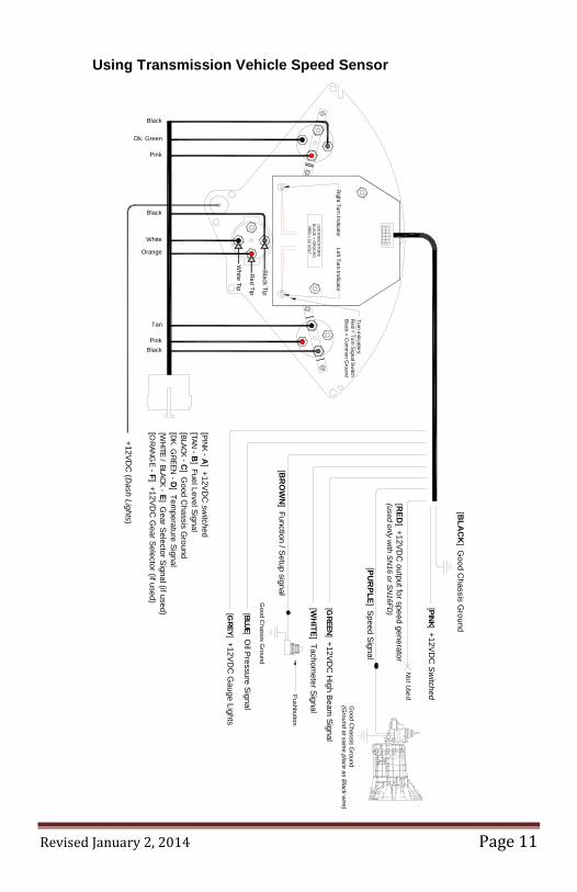
Using Transmission Vehicle Speed Sensor
Turn indicators:R
ed = Turn Signal Sw
itchB
lack = Com
mon G
round
LED
IND
ICA
TOR
SB
LAC
K = G
RO
UN
DR
ED
= 12 VO
LT
Left Turn IndicatorR
ight Turn Indicator
Tan
PinkBlack
[PINK - A
] +12VD
C sw
itched[TAN - B
] Fuel Level Signal
[ BLACK - C] G
ood Chassis G
round[ DK. G
REEN - D] Tem
perature Signal
[WHITE / BLACK - E
] Gear S
elector Signal (if used)
[ORAN
GE - F] +12V
DC
Gear S
elector (if used)
+12VD
C (D
ash Lights)
[BLA
CK
] Good C
hassis Ground
[ PINK] +12VD
C S
witched
[RED
] +12VD
C output for speed generator
(used only with S
N16 or S
N16FD
)
[PUR
PLE] S
peed Signal
[GREEN
] +12VD
C H
igh Beam
Signal
[WH
ITE] Tachom
eter Signal
[BR
OW
N] Function / S
etup signal
Good C
hassis Ground
Pushbutton
[BLUE] Oil P
ressure Signal
[GREY
] +12VD
C G
auge Lights
Not Used
Good C
hassis Ground
(Ground at sam
e place as Black w
ire)
Black
Dk. Green
Pink
Orange
White
White Tip
Black Tip
Red Tip
Black
Revised January 2, 2014 Page 12
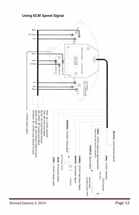
Using ECM Speed Signal
Turn indicators:R
ed = Turn Signal Switch
Black = Com
mon G
round
LED IN
DIC
ATOR
SBLAC
K = GR
OU
ND
RED
= 12 VOLT
Left Turn IndicatorR
ight Turn Indicator
Tan
PinkBlack
[PINK - A] +12VD
C sw
itched[TAN - B
] Fuel Level Signal[BLACK - C
] Good C
hassis Ground
[DK. GREEN - D
] Temperature Signal
[WHITE / BLACK - E
] Gear Selector Signal (if used)
[ORANG
E - F] +12VDC
Gear Selector (if used)
+12VDC
( Dash Lights)
[BLA
CK
] Good C
hassis Ground
[PINK] +12VDC
Switched
[ RED
] +12VDC
output for speed generator(used only w
ith SN
16 or SN16FD
)
[ PUR
PLE] Speed Signal
[GREEN] +12VD
C H
igh Beam Signal
[WH
ITE] Tachom
eter Signal
[BR
OW
N] Function / Setup signal
Good C
hassis Ground
Pushbutton
[BLUE] Oil Pressure Signal
[GREY] +12VD
C G
auge Lights
Not Used EC
M C
omputer
Speed Signal(U
sually a Green W
ire)
Black
Dk. Green
Pink
Orange
White
White Tip
Black Tip
Red Tip
Black
Revised January 2, 2014 Page 13
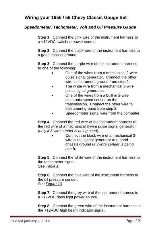
Wiring your 1955 / 56 Chevy Classic Gauge Set
Speedometer, Tachometer, Volt and Oil Pressure Gauge
Step 1: Connect the pink wire of the instrument harness to a +12VDC switched power source. Step 2: Connect the black wire of the instrument harness to a good chassis ground. Step 3: Connect the purple wire of the instrument harness to one of the following:
• One of the wires from a mechanical 2-wire pulse signal generator. Connect the other wire to instrument ground from step 2.
• The white wire from a mechanical 3-wire pulse signal generator.
• One of the wires from a built in 2-wire electronic speed sensor on the transmission. Connect the other wire to instrument ground from step 2.
• Speedometer signal wire from the computer.
Step 4: Connect the red wire of the instrument harness to the red wire of a mechanical 3-wire pulse signal generator (only if 3-wire sender is being used).
• Connect the black wire of a mechanical 3-wire pulse signal generator to a good chassis ground (if 3-wire sender is being used).
Step 5: Connect the white wire of the instrument harness to the tachometer signal. See Table 1
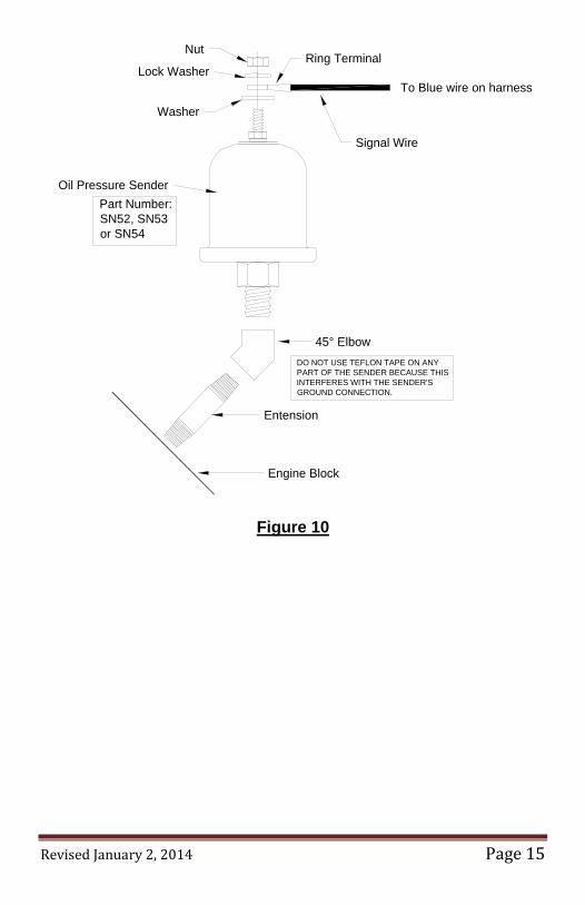
Step 6: Connect the blue wire of the instrument harness to the oil pressure sender. See Figure 10 Step 7: Connect the grey wire of the instrument harness to a +12VDC dash light power source. Step 8: Connect the green wire of the instrument harness to the +12VDC high beam indicator signal.
Revised January 2, 2014 Page 14
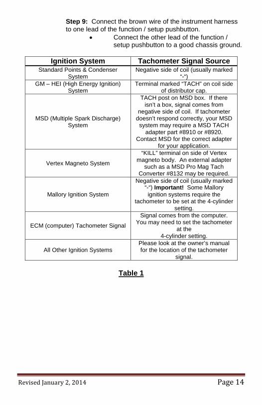
Step 9: Connect the brown wire of the instrument harness to one lead of the function / setup pushbutton.
• Connect the other lead of the function / setup pushbutton to a good chassis ground.
Table 1
Ignition System Tachometer Signal Source Standard Points & Condenser
System Negative side of coil (usually marked
“-“) GM – HEI (High Energy Ignition)
System Terminal marked “TACH” on coil side
of distributor cap.
MSD (Multiple Spark Discharge) System
TACH post on MSD box. If there isn’t a box, signal comes from
negative side of coil. If tachometer doesn’t respond correctly, your MSD system may require a MSD TACH
adapter part #8910 or #8920. Contact MSD for the correct adapter
for your application.
Vertex Magneto System
“KILL” terminal on side of Vertex magneto body. An external adapter
such as a MSD Pro Mag Tach Converter #8132 may be required.
Mallory Ignition System
Negative side of coil (usually marked “-“) Important! Some Mallory ignition systems require the
tachometer to be set at the 4-cylinder setting.
ECM (computer) Tachometer Signal
Signal comes from the computer. You may need to set the tachometer
at the 4-cylinder setting.
All Other Ignition Systems Please look at the owner’s manual for the location of the tachometer
signal.
Revised January 2, 2014 Page 15
Engine Block
Entension
45° Elbow
Ring Terminal
Oil Pressure Sender
Signal Wire
Washer
Lock Washer
Nut
DO NOT USE TEFLON TAPE ON ANY PART OF THE SENDER BECAUSE THIS INTERFERES WITH THE SENDER'S GROUND CONNECTION.
To Blue wire on harness
Part Number:SN52, SN53 or SN54
Figure 10
Revised January 2, 2014 Page 16
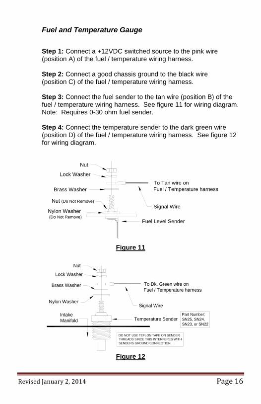
Fuel and Temperature Gauge
Step 1: Connect a +12VDC switched source to the pink wire (position A) of the fuel / temperature wiring harness.
Step 2: Connect a good chassis ground to the black wire
(position C) of the fuel / temperature wiring harness. Step 3: Connect the fuel sender to the tan wire (position B) of the fuel / temperature wiring harness. See figure 11 for wiring diagram. Note: Requires 0-30 ohm fuel sender. Step 4: Connect the temperature sender to the dark green wire (position D) of the fuel / temperature wiring harness. See figure 12 for wiring diagram.
Nut
Lock Washer
Signal Wire
Brass Washer
Nut (Do Not Remove)
Nylon Washer (Do Not Remove)
Fuel Level Sender
To Tan wire onFuel / Temperature harness
Figure 11
IntakeManifold Temperature Sender
Signal Wire
Lock Washer
Nut
Brass Washer
Nylon Washer
To Dk. Green wire on Fuel / Temperature harness
DO NOT USE TEFLON TAPE ON SENDER THREADS SINCE THIS INTERFERES WITH SENDERS GROUND CONNECTION.
Part Number: SN25, SN24, SN23, or SN22
Figure 12
Revised January 2, 2014 Page 17
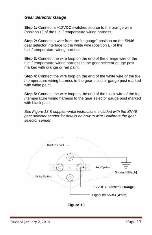
Gear Selector Gauge
Step 1: Connect a +12VDC switched source to the orange wire (position F) of the fuel / temperature wiring harness. Step 2: Connect a wire from the “to gauge” position on the SN46 gear selector interface to the white wire (position E) of the fuel / temperature wiring harness. Step 3: Connect the wire loop on the end of the orange wire of the fuel / temperature wiring harness to the gear selector gauge post marked with orange or red paint. Step 4: Connect the wire loop on the end of the white wire of the fuel / temperature wiring harness to the gear selector gauge post marked with white paint. Step 5: Connect the wire loop on the end of the black wire of the fuel / temperature wiring harness to the gear selector gauge post marked with black paint. See Figure 13 & supplemental instructions included with the SN46 gear selector sender for details on how to wire / calibrate the gear selector sender.
White-Tip Post
Red-Tip Post
Black-Tip Post
Signal (to SN46) [White]
Ground [Black]
+12VDC (Switched) [Orange]
Figure 13
Revised January 2, 2014 Page 18
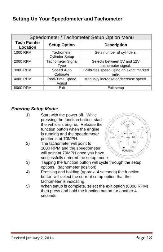
Setting Up Your Speedometer and Tachometer
Speedometer / Tachometer Setup Option Menu Tach Pointer
Location Setup Option Description
1000 RPM Tachometer Cylinder Setup
Sets number of cylinders.
2000 RPM Tachometer Signal Type
Selects between 5V and 12V tachometer signal.
3000 RPM Speed Auto Calibrate
Calibrates speed using an exact marked mile.
4000 RPM Real-Time Speed Adjust
Manually increase or decrease speed.
8000 RPM Exit Exit setup
Entering Setup Mode: 1) Start with the power off. While
pressing the function button, start the vehicle’s engine. Release the function button when the engine is running and the speedometer pointer is at 70MPH.
2) The tachometer will point to 1000 RPM and the speedometer will point at 70MPH once you have successfully entered the setup mode.
3) Tapping the function button will cycle through the setup options. (tachometer position)
4) Pressing and holding (approx. 4 seconds) the function button will select the current setup option that the tachometer is indicating.
5) When setup is complete, select the exit option (8000 RPM) then press and hold the function button for another 4 seconds.
100
50
0
OILVOLTS
18
13
8
x1000RPM
MPH
140
120
1008060
40
20
0
87
654321
0
000000 0
Revised January 2, 2014 Page 19
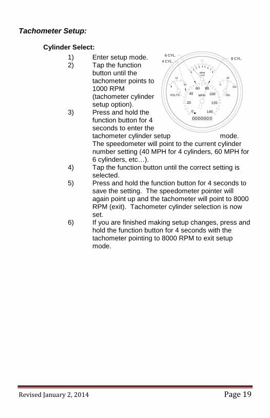
Tachometer Setup:
Cylinder Select: 1) Enter setup mode. 2) Tap the function
button until the tachometer points to 1000 RPM (tachometer cylinder setup option).
3) Press and hold the function button for 4 seconds to enter the tachometer cylinder setup mode. The speedometer will point to the current cylinder number setting (40 MPH for 4 cylinders, 60 MPH for 6 cylinders, etc…).
4) Tap the function button until the correct setting is selected.
5) Press and hold the function button for 4 seconds to save the setting. The speedometer pointer will again point up and the tachometer will point to 8000 RPM (exit). Tachometer cylinder selection is now set.
6) If you are finished making setup changes, press and hold the function button for 4 seconds with the tachometer pointing to 8000 RPM to exit setup mode.
000000 0
01
2 3 4 5 67
8
0
20
4060 80
100
120
140
MPH
RPMx1000
8
13
18
VOLTS OIL
0
50
100
4 CYL.6 CYL.
8 CYL.
Revised January 2, 2014 Page 20
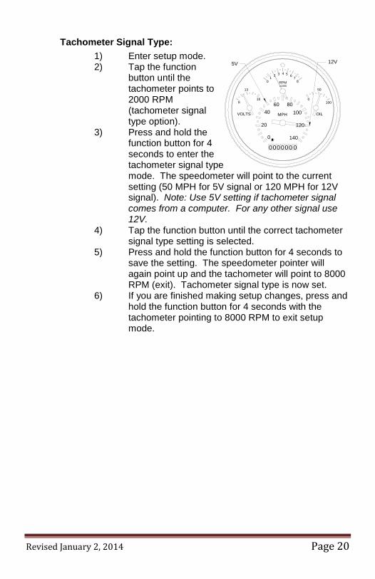
Tachometer Signal Type: 1) Enter setup mode. 2) Tap the function
button until the tachometer points to 2000 RPM (tachometer signal type option).
3) Press and hold the function button for 4 seconds to enter the tachometer signal type mode. The speedometer will point to the current setting (50 MPH for 5V signal or 120 MPH for 12V signal). Note: Use 5V setting if tachometer signal comes from a computer. For any other signal use 12V.
4) Tap the function button until the correct tachometer signal type setting is selected.
5) Press and hold the function button for 4 seconds to save the setting. The speedometer pointer will again point up and the tachometer will point to 8000 RPM (exit). Tachometer signal type is now set.
6) If you are finished making setup changes, press and hold the function button for 4 seconds with the tachometer pointing to 8000 RPM to exit setup mode.
100
50
0
OILVOLTS
18
13
8
x1000RPM
MPH
140
120
1008060
40
20
0
87
654321
0
000000 0
5V 12V
Revised January 2, 2014 Page 21
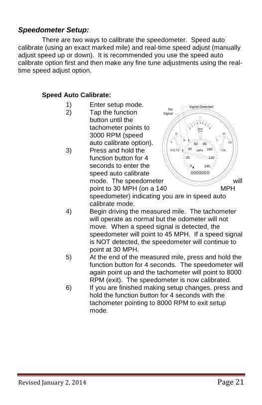
Speedometer Setup: There are two ways to calibrate the speedometer. Speed auto calibrate (using an exact marked mile) and real-time speed adjust (manually adjust speed up or down). It is recommended you use the speed auto calibrate option first and then make any fine tune adjustments using the real-time speed adjust option.
Speed Auto Calibrate: 1) Enter setup mode. 2) Tap the function
button until the tachometer points to 3000 RPM (speed auto calibrate option).
3) Press and hold the function button for 4 seconds to enter the speed auto calibrate mode. The speedometer will point to 30 MPH (on a 140 MPH speedometer) indicating you are in speed auto calibrate mode.
4) Begin driving the measured mile. The tachometer will operate as normal but the odometer will not move. When a speed signal is detected, the speedometer will point to 45 MPH. If a speed signal is NOT detected, the speedometer will continue to point at 30 MPH.
5) At the end of the measured mile, press and hold the function button for 4 seconds. The speedometer will again point up and the tachometer will point to 8000 RPM (exit). The speedometer is now calibrated.
6) If you are finished making setup changes, press and hold the function button for 4 seconds with the tachometer pointing to 8000 RPM to exit setup mode.
000000 0
01
2 3 4 5 67
8
0
20
4060 80
100
120
140
MPH
RPMx1000
8
13
18
VOLTS OIL
0
50
100
NoSignal
Signal Detected
Revised January 2, 2014 Page 22
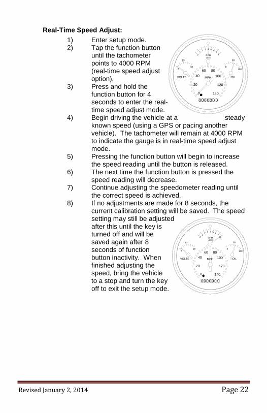
Real-Time Speed Adjust: 1) Enter setup mode. 2) Tap the function button
until the tachometer points to 4000 RPM (real-time speed adjust option).
3) Press and hold the function button for 4 seconds to enter the real-time speed adjust mode.
4) Begin driving the vehicle at a steady known speed (using a GPS or pacing another vehicle). The tachometer will remain at 4000 RPM to indicate the gauge is in real-time speed adjust mode.
5) Pressing the function button will begin to increase the speed reading until the button is released.
6) The next time the function button is pressed the speed reading will decrease.
7) Continue adjusting the speedometer reading until the correct speed is achieved.
8) If no adjustments are made for 8 seconds, the current calibration setting will be saved. The speed setting may still be adjusted after this until the key is turned off and will be saved again after 8 seconds of function button inactivity. When finished adjusting the speed, bring the vehicle to a stop and turn the key off to exit the setup mode.
000000 0
01
2 3 4 5 67
8
0
20
4060 80
100
120
140
MPH
RPMx1000
8
13
18
VOLTS OIL
0
50
100
100
50
0
OILVOLTS
18
13
8
x1000RPM
MPH
140
120
1008060
40
20
0
87
654321
0
000000 0