1941 - 42 hudson 6 tune-up...
TRANSCRIPT

H U D S O N
TUNE-UP SPECIFICATIONS and ADJUSTMENTS
HUDSON 6 MODELS 1941-1942

H U D S O N T E C H 2004

1941-1942 Hudson Six
Tune-up Specifications
1941 1942 Model Serial No. Model Serial No. Six Traveler 10T 10-101 20T 20-101 Six Deluxe 10P 10-101 20P 20-101 Super Six 11 11-101 21 20-101 Commodore Six 12 12-101 22 22-101 Business Cars 10C 10-101 20C 20-101 Big Boy 18 18-101 28 28-101 See Model 10 Note (below) See Model 20 Note (below)
MODEL 10 NOTE:-3"x 5” engine optional (when this engine used all equipment listed below for Model 11 used on these cars). Serial No. plate carries identification prefixes as follows: 3"x 4-1/8" Eng. 'T' (Traveler), 'P' (Deluxe), 'C' (Commercial). 3"x5" Engine additional letter 'L' thus: 'TL', 'PL', 'CL'. MODEL 20 NOTE:-3" x 5” engine optional (when this engine used all equipment listed below for Model 21 used on these cars). Serial No. plate carries identification prefixes as follows: 3-x41/8" Eng. 'T' (Six), ‘P' (Deluxe), 'C' (Commercial). 3 x 5” Engine an additional letter 'L' thus: 'TL','PL','CL'. SERIAL NUMBER: - First No. for each model as shown in table above. Stamped on plate on right front door hinge pillar post. NOTE - First two figures of number indicate model thus: 10-101. ENGINE NUMBER: - Same as Serial No. On top of cylinder block between #1 and 2 exhaust flanges.
TUNE-UP COMPRESSION: Ratio & Pressure-As follows: Model Ratio Pressure (At 125 RPM) 10, 20 7.25-1 125 lbs. 10, 20 (3x5" Eng.) 6.5-1 120 lbs. 11, 12,18 ('41) 6.5-1 120 lbs. 21, 22, 28 ('42) 6.5-1 120 lbs. VACUUM READING: - 18-21" steady idling at 600 RPM. FIRING ORDER: - 1-5-3-6-2-4. See diagram. SPARK PLUGS: - Champion Spec. J9 Hudson. 14 MM. Gaps - .032" Opt’l. Plug Note - Champion J-5 (Hotter) for continuous slow speed service or J-10 Commercial (Cooler) for continuous high speed service. IGNITION: See Coil, Condenser, and Distributor. Breaker Gap - .020" Cam Angle 35, (Closed). Automatic Advance - 11.75º max. at 1570 RPM (dist). Vacuum Advance - 7.5º distr. with 10" vacuum. IGNITION TIMING: See Ignition Timing. Std. Setting - 1/2" flywheel travel BTDC. with 2nd graduation on flywheel ahead of mark "UDC.I.-6/" 11
at indicator on left front face of rear motor support above starter. CARBURETION: See Carburetor & Carb. Equipment. Idle Setting (Single Carb.) - Idle screw ¾-1½ turn open. Idle speed 580-600 RPM. Idle Setting (Dual Carb.) -Both idle screws ¼-1¼ turn open (461-S), ½-1½ turn open (501-S). Idle speed 580-600 RPM. Float Level (Single Carb.) - 3/8" from top of bowl cover projection to top of soldered seam on free end of float with valve seated (invert to check). Float Level (Dual Carb.) - 3/32" (461-S), 1/8" (501- S) from gasket seat on bowl cover to top of float at each end (invert to check). Accelerating Pump (Single Carb.) - Lower hole (medium stroke) Normal. Inner hole (Summer), Upper hole (Winter) for temperature extremes. Accelerating Pump (Dual Carb.) - Outer hole (max. stroke) Normal. Inner hole (min.) when required. Fuel Pump Pressure: 3½ lbs. max. (AF), 4½ lbs. max. (AK). MANIFOLD HEAT CONTROL: Models 10, 18 ('41), 20,28 (142). Manual type. Located on manifold behind carburetor. Setting - Arrow on valve cover pointing to "W" cast on top of manifold. Correct for Summer & Winter. Models 11, 12 ('41); 21,22 ('42) - Automatic thermostatic type. No adjustment. See that valve operates freely. NOTE - This type used on Models 10 and 20 with 3"x5" Engine. VALVES: See Valve Timing. Tappet Clearance (1941) - .006" Intake, 008" Exhaust Hot and idling except Model 10 with label on valve cover specifying .010" Intake, .012" Exhaust (Hot). Remove right front fender plate for access to valves. Tappet Clearance (1942 20T, 20P, 20C) .010" Intake, .012" Exhaust with engine Hot and Idling. Tappet Clearance (1942 20TL, 20PL, 20CL, 21, 22, 28C) - .006" Intake, .008" Exhaust, Hot and Idling. NOTE: 20TL, 20PL, and 20CL - 3" x 5" engine. STARTING: See Battery, Starter, Generator, Regulator.
- 1 -
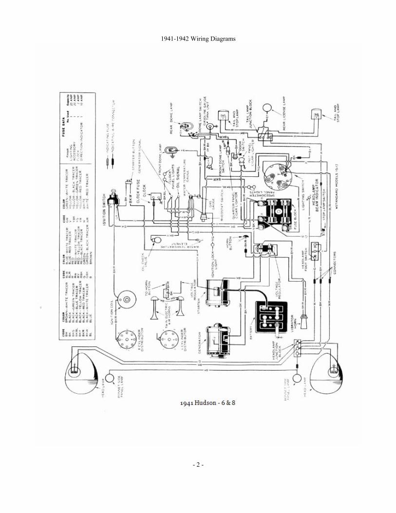
1941-1942 Wiring Diagrams
- 2 -
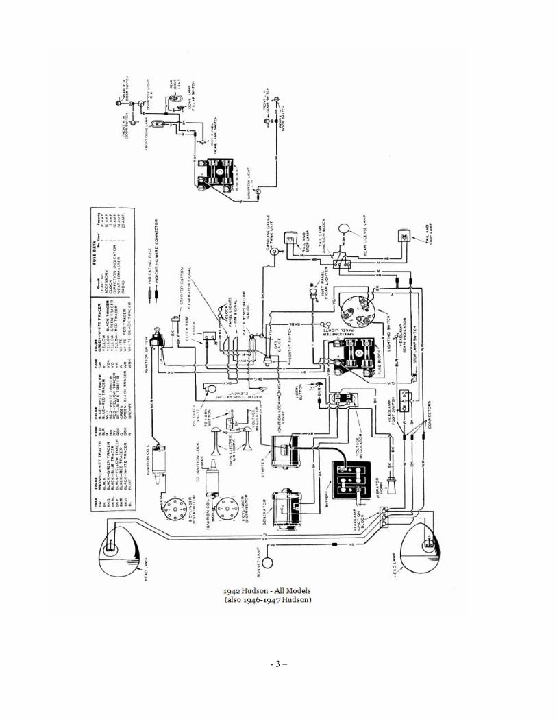
- 3 –
IGNITION
Ignition Switch: - Mitchellock Model 24-B, No. 8797. Ignition Lock - Briggs & Stratton B & S No. 50184. Key Series--H601 to H1100. Groove-No. 1. X, g COIL: Auto-Lite Model IG-4098. Mounted on the dash. IMPORTANT-Coil is hooked up reversed from con- ventional manner (as shown on 1940 diagram) with switch lead connected to terminal on high tension terminal end of coil, breaker lead to terminal - on opposite end. Will not operate satisfactorily if connected otherwise. Ignition Current - 2.5 amperes idling, 4.5 stopped. CONDENSER: Auto-Lite Part No. IGW-3075C. Capacity-.20-.25 microfarad. DISTRIBUTOR: Auto-Lite Model IGW-4203A. Single breaker, 6 lobe cam, full automatic advance type with auxiliary vacuum spark control. Breaker Gap - .020". Cam Angle or Dwell - 35º closed, 25º open (distr.) Breaker Arm Spring Tension - 17-20 ounces. Rotation - Counter-clockwise viewed from above. Distributor Automatic Advance Engine Degrees R.P.M Degrees R.P.M. Start 400 0 800 3 700 6 1400 6 1000 12 2000 9 1300 18 2600 11.75 1570 23.5 3140 Vacuum Spark Control - On distributor hold-down plate, linked to quadrant scale on distributor. Provides additional advance at speeds above idling except when engine accelerated or operated with wide open throttle (spark retarded by return spring within unit).
Vacuum Advance Distr. Degrees Eng. Degrees Vacuum (" of HG) Start 0º 6¾" 4º 8º 8½" 7.5º 15º 10" Fuel Compensator - Manual adjustment for octane rating of fuel used. See Ignition Timing for setting. Distributor Removal: - Mounted at top rear of cylinder head. To remove, disconnect vacuum line, take out cylinder head stud nuts on hold-down plate.
IGNITION TIMING IGNITION TIMING: - Initial Setting - ½" (two spaces) BTDC. for fuel of approximately 72 Octane rating. Flywheel Marks - ''UDC.1-6/'' at TDC with 4 graduations (¼" apart) ahead of this mark. Timing - With #1 piston on compression, turn engine over until second graduation before flywheel mark
"UDC.1-6/" lines up with pointer on left front face of rear motor support above starter. Loosen vacuum advance diaphragm screw on quadrant scale, rotate distributor counter-clockwise to limit of slot. then slowly rotate clockwise until contacts begin to open, tighten diaphragm screw securely. Check Fuel Compensator Setting below. Timing (Using Synchroscope) - Recommended method. Mark flywheel with white chalk or paint. Idle engine, adjust distributor (above). Fuel Compensator Setting - Road test car (engine warm). When running at 8 MPH slight ping should occur between 10-15 MPH when accelerating with wide open throttle. To adjust, loosen vacuum unit link screw on distributor quadrant, rotate distributor one graduation on quadrant scale clockwise (if no ping), counter-clockwise (if ping too severe). Final setting must not be more than 1" (4th graduation) before "UDC.1-6/" flywheel mark.
CARBURETOR SINGLE BARREL
(Models 10-see Note, 18, 20-see Note, 28) - Carter Model WA-1, Type 454-S. 11/4" Single Barrel, downdraft type with Fast Idle and Carter Climatic Control automatic choke). Model 10, 20 Note - Cars with 3"x 5” Engine have dual carburetor (same as Models 11, 21 below). Idle Adjustment - With engine warm, set throttle stop-screw for 600 RPM hot or slow idle speed (fast idle inoperative), adjust idle adjusting screw so engine fires smoothly and vacuum reading at maximum (screw ¾-1½ turns open-turn screw in for leaner setting), recheck idle speed. Accelerating Pump Setting - Pump arm has three holes for pump link engagement. Set as follows: Lower Hole (med. stroke) - Normal setting. Inner Hole (min.)-Hot weather or hi-test fuel. Upper Hole (max.) 0 -Cold weather or low-test fuel. Float Level - 3/8" from top of bowl cover projection, to top of soldered seam on float at free end.
CARBURETOR DUAL (DOUBLE BARREL)
(Models 11, 12,21,22): Carter Model WDO, Type 461-S (1941 before No. 2150), Type 501-S (1941 After No. 2150 & 1942). 1” Dual (double barrel), downdraft types with Fast Idle and Carter Climatic Control (automatic choke). NOTE - Type 461-S, only, has "Slow-Closing Throttle" dashpot device. Idle Adjustment - With engine warm, set throttle stop-screw for 580-600 RPM hot or slow idle speed (fast idle inoperative). Adjust both idle screws (two used, one for each barrel) in succession until engine fires smoothly. - 4 -

Carburetor – Dual (Cont’d) Final setting should be 1/4-11/4 turn open (461-S), ½-1½ turn open (501-S) from inner seated position. Turn screws in for leaner mixture. If vacuum gauge used, adjust for highest steady reading of the gauge. Readjust stop-screw for correct idling speed. Accelerating Pump Setting - Pump lever (under dust cover on bowl cover) has two holes for pump link engagement. Adjust as follows: Outer Hole (max. stroke) - Normal Setting. Inner Hole (min. stroke) - If less charge required. Float Level - 3/32" (461-S), 1/8" (501-S) from top of float to bowl cover with valve seated.
CARB. EQUIPMENT
Fast Idle (454-S): Integral with carburetor. Setting - Adjust by bending connecting link offset for 5/8" choke valve opening with throttle stop-screw against (not on) first step of fast idle cam. Fast Idle (461-S, 501-S): Integral with carburetor. Setting (461-S) - With choke valve closed, adjust fast idle screw for .018" throttle opening. Setting (501-S) - With choke valve closed and fast idle screw on high lobe of fast idle cam, turn fast idle screw in until throttle opening is .045". Automatic Choke: - Carter Climatic Control. Setting (454-S, 461-S) - Centered (at index mark). Setting (501-S) - One Notch Lean (supersedes "Centered" setting originally specified for this model.) Air Cleaner: - AC oil wetted types. Car Cars with Replacement Model Standard Drive-Master Filter Elem. 10,18,20,28 1528159 1542384 Type #1 11,12,21,22 1528161 1542385 Type #2 Fuel Pump: AC Type AF, No. 1523753 (10,18,20,28 Pass. Cars); Type AK, No. 1523289 (All others). Pump Exchange No. 509 (Type AF), 499 (Type AK). Gasoline Gauge: - King-Seeley Electric. K-S No. 8305 (Dash Unit-stamped 'G'), No. 7550 (Tank Unit).
BATTERY
BATTERY: - National, Type HT-17. 6 volt, 17 plate, 96 ampere hour capacity (20 hour rate). Starting Capacity - 120 amperes for 20 minutes. Zero Capacity - 300 amperes for 3.5 minutes. Five second voltage - 4.24 volts. Grounded Terminal - Positive to frame. Engine Ground - Strap (rear motor support to frame). Dimensions – Length, 10-9/16, Width, 7¼”. Height, 7-13/16". Location - On left side under engine hood.
STARTER
Auto-Lite Model MZ-4092. Armature No. MZ-2138. Drive - Inboard Barrel type Bendix No. A- 1684. Rotation - Counter-clockwise at commutator end. Brush Spring Tension - 42-53 ozs. (new brushes). Cranking Engine - 150 RPM, 125 amperes, 5.4 volts.
Performance Data – MZ-4092 Torque R.P.M. Volts Amperes 0 ft. lbs 4300 5.5 70 2.55 “ “ 1325 5.0 200 4.95 “ “ 750 4.5 300 7.65 “ “ 220 4.0 400 7.8 “ “ Lock 3.0 420 11.8 ” “ Lock 4.0 560 Removal: - On left front face of rear motor support. To remove, take out flange mounting screws. Starting Switch: - A-L Model SS-4001. Magnetic type. Auto-Lite Model GDS-4801A (Std. 10, 18, 20, 28); GEC-4801A (Std. 11, 12, 21, 22, 20P Conv. Sedan, 20 with 3" x 511 Eng., All Cars with DriveMaster). Third brush control type with vibrating voltage regulator. Ventilated by fan on drive pulley. Armature - GDF-2006F (ODS), GDZ-2006F (GEM) Maximum Charging Rate (GDS) - 32-34 amperes (cold), 8.0 volts, 2900 RPM or approx. 35 MPH. (GEC) 39-43 amperes (cold), 8.0 volts, 3350 RPM or approx. 43 MPH. Actual charging rate controlled by Voltage Regulator (see Regulator). Ground generator 'F' terminal, when checking generator output. Charging Rate Adjustment - See Regulator. Third brush setting (GDS) 1 commutator bar minus 1 mica strip min., I commutator bar max. from insulated (nearest main brush). (GEC) 1 commutator bar min., 1 commutator bar plus 1 mica strip max. Adjust by shifting 3rd brush.
Performance Data - GDS-4801A Cold Hot Amperes Volts R.P.M. Amperes Volts R.P.M 0 6.4 920 0 6.4 960 4 6.6 1050 4 6.65 1120 8 6.8 1175 8 6.9 1280 12 7.0 1300 12 7.1 1430 16 7.2 1450 16 7.35 1640 20 7.4 1600 20 7.6 1900 24 7.6 1820 24 7.8 2320 28 7.8 2075 27.5 8.0 3400 338 8.0 2900
- 5 -
Starter (Cont’d) Performance Data - GEC-4801A
Cold Hot Amperes Volts R.P.M. Amperes Volts R.P.M 0 6.4 960 0 6.4 1040 4 6.55 1060 4 6.6 1140 8 7 160 8 6.8 1280 12 6.85 1280 12 6.95 1440 16 7.0 1400 16 7.15 1600 20 7.15 1550 20 7.35 1820 24 7.25 1700 24 7.55 2090 28 7.5 1890 28 7.75 2440 32 7.65 2100 32 7.9 3000 36 7.8 2375 34 8.0 3800 41 8.0 3350 Rotation -Counter- clockwise at commutator end. Brush Spring Tension - 53 ozs. max. (new brushes) Field Current - 1.65-1.82 amperes (GDS), 1.60-1.78 amperes (GEC) at 6.0 volts. Motoring Current - 5.10-5.45 (GDS), 4.85-5.4 (GEC) amperes at 6.0 volts. Removal: - Pivot mounted at left front of engine. To remove, take out pivot and clamp bolts. Belt Adjustment: - 3/41, slack midway between pulleys.
REGULATOR REGULATOR: - Auto-Lite VRR-4001A. Cutout Relay and vibrating Voltage Regulator in case on dash. Cutout Relay has extra set of contacts for Generator Teleflash Indicator control. NOTE - Regulator enclosed In closefitting metal cover on dash.
Cutout Relay Cuts In - 6.4-6.6 volts, 825 RPM. 9.4 MPH. Cuts Out - 4.2-4.8 volts (approx. 4-6 amps. disch.). Contact Gap - .015" min. ground contacts closed (ground contacts open when main contacts close). Air Gap - 031-.034" at hinge end of core with contacts open (ground contacts closed).
Voltage Regulator Setting - 7.1-7.4 volts at 70º F. To Check (without breaking seals) - Connect ammeter in charging line at regulator 'B' terminal, voltmeter between this terminal and ground. Operate generator at speed of 30 MPH charging battery until voltage is constant. Voltmeter reading should be within limits of 7.1-7.4 volts at 70º F. To Adjust (with cover removed) - Change regulator armature spring tension by bending lower spring hanger slightly. ). Contact Gap - .012” minimum (armature against stop). Air Gap - .048-.052” with contacts just opening.
LIGHTING
LIGHTING: - Headlamps - Hall 'Sealed Beam' type. Headlamp Adjustment - Aim upper beam of each headlamp straight ahead with hot spot centered on horizontal line 3" below lamp center height. Beam Indicator - Red pilot bulb on speedometer dial. Lighted with Country (upper) beam in use. Direction Indicator - Optional equipment..
Switches – 1941
Lighting - Douglas. Hudson No. 147835. Beam Selector - R-B-M Model 2484. Instrument - R-B-M. Hudson No. 160092.
Switches – 1942 Lighting - Douglas. Hudson Part No. 200417. Beam Selector - R-B-M. Hudson Part No. 164439. Instrument - R-B-M. Hudson Part No. 160092.
Bulb Specifications – 1941
Position Candlepower Mazda No. Headlamps Sealed Beam Side Panel (Parking) 1½ 55 Fender Lamp (see Note) 3 63 Speedometer, Elec. Clock 1½ 55 Generator & Oil Signals 1½ 55 Ign. Lock, Mech. Clock 1 51 Beam & Direct. Indic 1 51 Stop & Tail 21-3 1154 Rear License 3 63 Dome 15 87 NOTE - 21 cp. No. 1129 for Direction Indicator.
Bulb Specifications – 1942
Position Candlepower Mazda No. Headlamps Sealed Beam Bonnet Side Panel (Park) 1.5 55 Fender Lamp (see Note) 3 63 Ign. Lock, Clock 1.5 55 Indicators (Gen.,Oil,Beam,Dir.) 1 51 Speedometer 1 51 Stop & Tail 21-3 1154 Rear License 3 63 Dome & Courtesy 15 88 NOTE-No. 1158 21-3 cp. used with Direction Indicator
MISC. ELECTRICAL
SIGNAL LIGHTS: - Generator Charge and Oil Pressure Indicators used. Hudson Teleflash Electric type. FUSES: - Lighting - 30 ampere. Lower fuse on fuse block on lower edge of instrument panel to right of steering column. Accessory - 30 amp. Top fuse on block. NOTE - Silver-plated fuses used. 30 amp. fuse supersedes 20 ampere fuse used on early cars.
- 6 -

MISC. ELECTRICAL (Cont’d) Twin Horns (1941) - 30 ampere. On engine dash. Direction Indicator - 10 amp. near speedometer. Electric Clock - 2 amp. in case behind clock. NOTE - Feed wire for electric clock on early cars connected to fuse block 'Bat' terminal. Should be changed to accessory 'X' terminal (as shown). CIRCUIT BREAKER: - Used on Drive-Master Cars only. On fuse block. Protects Drive-Master circuit only. HORNS: Single - Schwarze Electric type. Std. on Models 10T, 18 (1941), 20T, 28 (1942). Twin - Sparton air electric type operated by relay. Fuse on dash. (Air Gap) .026-.030" high pitch (short), .032-.035" low pitch (long). Horn Relay: - R-B-M Model 6004. On dash. Contacts Close 3-4 volts (relay upright, terminals down).
ENGINE ENGINE SPECIFICATIONS (10T, 10P, 10C 1941; 20T, 20P, 20C 1942): 6 Cylinder, "L" Head type. Bore - 3". Stroke - 4-1/8". Displacement - 175 cubic inches. Rated Horsepower - 21.6. Developed Horsepower - 92 at 4000 RPM. Compression Ratio - 7.25-1 cast-iron head. Compression Pressure - 125 lbs. at 125 RPM (cranking speed). 90 lbs. minimum (10 lbs. max. variation). Vacuum Reading - Steady 18-21" idling at 600 RPM. ENGINE SPECIFICATIONS (10TL, 10PL, 10CL, 11, 12,18 1941; 20TL, 20PL, 20CL, 21, 22, 28 1942): 6 Cylinder, "L" Head type. Bore-3", Stroke - 5". Displacement - 212 cubic inches. Rated HP - 21.6. Developed Horsepower - 102 at 4000 RPM (all models except Models 18, 28), 98 at 4000 RPM (Models 18, 28 only). NOTE - Model 18 & 28 Engines equipped with single carburetor. Dual carburetor used on all other models. Compression Ratio - 6.50-1 cast-iron head. Compression Pressure - 120 lbs. at 125 RPM (cranking speed). 90 lbs. minimum (10 lbs. max. variation). Vacuum Reading - Steady 18-2", idling at 600 RPM. PISTONS: Lo-Ex aluminum alloy (1941), Cast Alloy (1942), cam ground type. Use finished replacement pistons. Weight - 10.5 ozs. (stripped). Length – 3-3/16". Removal - Pistons and rods removed from above. Clearance-Top .016". Skirt .0005-.001". See Fitting New Pistons below. Fitting New Pistons: - Use .0015" feeler 1/2" wide inserted between piston and cylinder wall on side opposite slot at right angles to pin. Pull to withdraw feeler must be within 3-4 lbs. Installing Pistons: Slot away from camshaft.
PISTON RINGS: - Two compression, two oil rings (one above pin, one below pin) per piston. Rings are square end type. Rings pinned to prevent rotation. Rings cut and notched to fit pin (clearance on pin equal to ring end gap). Ring Width End Gap Side Clearance Compression 3/32" 009-011" .001" Oil (upper) 3/16" 009-.011" .001" Oil (lower) 5/32" 009-.011" .001" PISTON PIN: - Diameter - 3/4". Length - 2-7/16". Floating type. Retained by locking rings. Pin Fit in Piston - .0003" clearance (hand push fit with piston heated to 200º F. Pin Fit in Rod Bushing - 0003" clearance. Replacement Pins: - Standard and .002", .005", .010" oversize. CONNECTING ROD: - Weight - 30¾ ozs. (3" x 41/8" engines), 30 ozs. (3" x 5" engines). Length - 8-5/8" (3" x 41/8" engines), 8-3/16" (3" x 5" engines). Crankpin Journal Diameter - 1-15/16". Lower Bearing - Lead alloy-lined (1941), babbitt lined (1942), Spun type. Exchange Rods furnished Standard Size and.010" Undersize. Clearance - .001". Sideplay - .006-.010". Bearing Adjustment: - None (no shims). Do not file rods or caps. Installing Rods: - Lower end of rods offset. Install rods with widest half of bearing toward the rear (# 1, 2, 4), toward front (# 3, 5, 6). Oil scoop on low end of rod toward camshaft. CRANKSHAFT: - 3 bearing, Integral counterweights. Journal Diameters - #1, 2-11/32"; #2, 2-3/8"; #3, 2-13/32". Bearings - Bronze-backed, babbitt-lined type. NOTE - No shim pack is used. Palnuts used in place of cotter pins to lock bearing cap nuts. Clearance - .001". Bearing Adjustment: - None (no shims). Do not file caps. End Thrust: - Taken by center bearing. Replace bearing if endplay excessive. NOTE - If new unfinished bearings installed, thrust face for center bearing must be faced for proper endplay. Endplay - .006-.012". CAMSHAFT: - Three bearing, gear driven type with new type bearings and timing gears. Production Change Models 10T, 10P, 10C (1941) - Two types of Camshaft used on the 3" x 41/8" Engine on these models only. 1942 Note - Camshaft Bearing Clearance and Timing Gear Backlash reduced from that used on previous models for quieter operation of valve mechanism. No valve spring dampeners used. - 7 -

CAMSHAFT (Cont’d) Journal Diameters - #1, 2.000"; #2, 1.968"; #3, 1.5625". Bearings - New type steel-backed, 'Bermax' (babbitt) lined bushings (formerly solid type babbitt). Clearance-.002-.0025" (1941), .001-.0025" (1942). End Thrust: - Thrust washer between camshaft flange and crankcase. Spring loaded button in camshaft hub bears against thrust plate on gear cover. NOTE- Service thrust washer available which can be split and installed without removing camshaft. Timing Gears: - Crankshaft gear cast-iron, camshaft gear laminated fiber. Tooth shape changed to 20º pressure angle (was 14½º) to provide quieter operation and longer gear life. Gears can be identified by figure 20 stamped on front face (crankshaft gear carries additional FRONT mark to Insure correct installation). Gears may be installed in sets only (not singly) on earlier car models (new type gears similar to previous type except for tooth pressure angle). NOTE - Camshaft gear available in .008" Oversize (can be distinguished from Standard Size by spot of yellow paint on front face). Backlash - .002-.004". Camshaft Setting: - Mesh marked crankshaft gear tooth between two marked teeth on camshaft gear. VALVES:- Head Diameter Stem Diameter Length All valves 1-3/8" 11/32" 5-11/32" Seat Angle Lift Stem Clearance Intake 45º 11/32" .0025" Exhaust 45º 11/32" .004" Valve Guides: Removable type. New longer exhaust guide used in 1942 (counterbore at top increased) and lengthened approx. 3/8", lower end of guide has been lengthened approx. 3/8" to compensate for increased length of counterbore at top). This new guide designed to reduce tendency of exhaust valves to stick due to fuel or oil gum formations at upper end of valve stem. Valve Springs: - Cadmium plated springs used with dampener installed on bottom with open side toward cylinder (Dampener used on 1941 cars only) Use suitable tool to install valve spring and seat NOTE - Car manufacturer recommends that dampeners be omitted whenever valves are serviced. Spring Free Length - 2-17/64". Spring Pressure Spring Length Valve Closed 40 lbs 2" Valve Open 80 lbs 1-21/32" NOTE - When springs removed, test for pressure. Replace if pressure below 34 lbs. at 2". Valve Lifters:-Roller shoe type, fitted in removable guides.
VALVE TIMING Tappet Clearance: - Two settings used. One setting for all 3" x5" Engines and early 1941 3" x 4-l/8" Engines (with first type camshaft) and a second setting for later 3" x 4-1/8" engines (with second type camshaft). Second setting on late 1941 3" x4-1/8" engines carried on instruction label attached to valve cover plate. Setting (All 3" x 5" engines and first 3" x 4-1/8" engines up to Car No. 6848) - .006" Intake, .008" Exhaust with engine running and at normal operating temperature. Setting (Later 1941 3" x 4-1/8" Engines after Car No. 6848 and all 1942 3" x 41/8" Engines) - .010" Intake, .012" Exhaust, Hot and Idling. NOTE - This setting carried on label attached to valve cover plate on late 1941 3" x 4-1/8" engines. Valve Timing (3" x4-1/8" Engine): See Camshaft setting.
Model 10 (1941) - Before Car #6848 Intake Valves - Open 10º40' BTDC. Close 60º ALDC. Exhaust Valves - Open 50º BLDC. Close 18º44' ATDC. These figures correct with .010" tappet clearance. Model 10 (1941)-After Car #6848 & Model 20 (1942) Intake Valves-Open 28*30' BTDC. Close 68*30'ALDC. Exhaust Valves-Open 52*40' BLDC. Close 32,40' ATDC. These figures correct with .010" tappet clear. Valve Timing Check-With .010" tappet clearance, intake valve opens 10,40' or .04411, piston travel BTDC. (1941 Cars before #6848), 28o3O' or .30631, piston travel BTDC. (1941 cars after #6848 and all 1942 cars) when a point on the flywheel 4 teeth (first 10,40, setting), 101/2 teeth (later 28o3O'setting) before dead center mark "UDC.1-6/" lines up with indicator in inspection hole in rear motor support above starter. Reset tappet clearance for correct running clearance. Valve Timing (3” x 5” Engine): See Camshaft Setting.
All Models (1941-42) Intake Valves - Open 10º40' BTDC. Close 60º ALDC. Exhaust Valves-Open 50º ALDC. Close l8º44' ATDC. These figures correct with .010” tappet clearance. Valve Timing Check - With .010" tappet clearance, #1 intake valve opens 10º40' BTDC. with piston .0562" before top dead center or point on flywheel approximately 4 teeth before dead center mark "UDC.1-6/" lines up with indicator in inspection hole in left rear motor support above starter. Reset tappet clearance to correct running clearance.
LUBRICATION LUBRICATION:-Duo-flo (pressure and positive splash) lubricating system. - 8 -
LUBRICATION (Cont’d) Oil Pump: - Oscillating plunger type, gear driven by camshaft. Mounted on right side of crankcase. Normal Oil Pressure - 4-12 lbs. with hot oil. No gauge used (see Oil Pressure Indicator below). NOTE - On 1942 engines, lower end of oil reservoir suction pipe (from oil pan to crankcase wall) extends to center of oil reservoir to insure constant oil supply to pump. Oil Check Valve: - Located on right side of crankcase at rear. Opens at 4-12 lbs. with hot oil. Operates dash signal to indicate oil flow. Oil Pressure Indicator: - Hudson Teleflash Oil Pressure Indicator. Consists of signal light on instrument panel operated by switch mounted on oil check valve. Crankcase Capacity: - 4½ quarts (refill), 5½ (dry). Servicing Note - When changing oil without removing oil pan, refill with 4½ quarts. If oil pan removed, place 1½ quarts in upper tray before oil pan installed, then 4 quarts through filler with pan in place.
COOLING COOLING SYSTEM: - Capacity - 13 quarts. See Hudson Shop Notes for radiator core removal. Water Pump: - Centrifugal, belt-driven, packless type with single outlet (no by-pass). Grease fitting provided for front & rear bearing lubrication. Thermostat: - Fulton. Choke type located in cylinder head water outlet. `Setting - Starts to open 150-155ºF. Fully open 185º. NOTE - Special high temperature thermostats available for use with ethylene glycol type anti-freeze, Starts to open 160-165ºF. Fully open 190ºF. Temperature Gauge: - King-Seeley Electric. K-S Nos. 8310 (Dash Unit-stamped 'T'), 7000 (Eng. Unit). NOTE - Temperature gauge inoperative with ignition 'off’. Pointer returns to ‘H' (hot) position.
CLUTCH CLUTCH: - Own Make. Single plate, cork insert type operating in oil. See Clutch Section for complete data. Driven Member - Cork Insert type (90 cork inserts on 9” size, 108 cork inserts on 10" size). Corks are .2031, thick. Inside-Diameter-Outside 10 101, 11 (no O.D.) 5¼” 9” 10, 10L, 11 (With O.D.) 6-3/8” 10" 12,18 6-5/8” 10" 20,21 (no O.D.) 5¼” 9” 20, 21 (with O.D.) 6-3/8” 10" 22,28 6-3/8” 10"
Pedal Adjustment (1941): Setting used dependent on connector link position on cross shaft lever. Normal setting (with connector link In center hole on cross shaft lever) 11/21, clearance between underside of toeboard and center of clutch pedal clamp bolt. Second setting (with connector link in lower hole for lighter clutch pedal pressure) clearance increased to 2". To adjust, loosen lock nut on connector link above clevis, take out clevis pin and turn clevis in or out for correct clearance. Check Automatic Clutch Control adjustment if used. Pedal Adjustment (1942): Clearance between underside of toeboard and top of pedal shaft should be 11/2" with link engaged in pedal and cross-shaft levers as given in table below. To adjust, loosen locknut on adjusting link above clevis, take out clevis pin (at lower end of link), adjust length of rod for proper clearance by turning clevis in or out on adjusting link. Model Top Bottom 20T, 20P, 20C - Inner Hole Outer Hole 20TL, 20PL, 20CL; 21 Outer Hole Outer Hole 22,24,25,27,28 & Outer Hole Center Hole - All Six & Eight cylinder cars with Vacumotive
Drive, Drive-Master, or Overdrive. Removal: - Remove transmission (see Transmission Removal following). Drain clutch oil by turning engine over until plug on flywheel is accessible through timing inspection hole in rear engine support plate above starter, remove plug, turn engine over 1/3 revolution until star on flywheel visible through timing hole (drain hole then at bottom), allow lubricant to be drained. Loosen mounting bolts in clutch cover rim to release spring tension, remove bolts and lift clutch assembly off car. NOTE - See Installation Note following Transmission Removal for Clutch Throwout Bearing Oil Seal.
VACUMOTIVE DRIVE Vacumotive Drive: Automatic clutch control. Optional. NOTE - Governor switch changed during production.
TRANSMISSION TRANSMSSION: - Own Make. New all helical gear, constant-mesh type with synchro-mesh (Second and High), sliding gears (Low & Reverse) and steering column gear shift. NOTE-External shift rail locks not used but are available in Accessory Kits for installation on cars operated in mountainous regions where Second Gear operation required for long periods. Transmission Control: - Hudson 'Handy-Shift' type. - 9 -

TRANSMISSION (Cont’d) Removal: - Transmission can be removed from inside car as follows: Take off accelerator pedal by removing cotter pins in anchor bracket and bell crank link clevis pins. Move steering column rubber hole cover up out of way. Remove floor mat by taking out screws at kick pads on dash and mat trim clips. Remove front seat cushion and transmission floor opening cover (CAUTION-Accelerator pedal operating rod should be secured so as not to drop on starter switch). Disconnect front universal by taking out four nuts and lock plates on U-bolts. Release clutch pedal return spring. Remove two cross shaft bracket bolts, clutch control link clevis pin and clutch pedal assisting spring. Remove Handy Shift control tube to-transmission shift rod cotter pin, washer and grommet; transmission casing lower anchor bracket screws and anchor bracket; transmission case outer lever retainer nut and retainer nut washer; and lever. Remove two flywheel guard- to-clutch housing screws and two rear engine mounting bolts (CAUTION - Do not remove rear engine mounting-to clutch housing bolt). Jack rear of engine up 1/21, off frame. Remove clutch housing to transmission bolts. Disconnect speedometer cable from transmission. Pull transmission back and lift out. Installation Note - Wrap one strand of soft wire around throw-out bearing oil seal to prevent leather curling over when transmission installed (twist wire with ends extending up through clutch housing so that it will come off the seal after transmission installed).
DRIVE-MASTER TRANSMISSION Drive-Master: - Conventional 3-speed transmission with automatic gear shifting between second and high gears in conjunction with Vacumotive Drive (automatic clutch control). Optional equipment.
OVERDRIVE Overdrive: - Warner Model AS1-R9B with electrical 'kick-down' control (new type - no centrifugal clutch pawls used). Optional equipment. 1941 Governor Switch Change to Correct Late Cut In - New Governor Switch Part No. 162867 with purple dots on terminal screw heads and purple band around switch has reversed oil threads in shaft bushings to keep transmission lubricant out of switch, overcoming improper operation of switch. Used on Late '41 cars. Overdrive Transmission Removal - Same as standard transmission removal (above) except that overdrive control and wiring connections must be disconnected. Overdrive Solenoid - Delco-Remy. Hudson #163305. Throttle Switch - Cole-Hersee. Hudson No. 162594. Adjust position of contact washer on accelerator pedal rod so that it just contacts switch plunger with carburetor throttle in wide open position.
Governor Switch-Bendix No. 162867.NOTE-Changed to new type with purple dots on terminals.
UNIVERSALS UNIVERSAL JOINTS: - Spicer. Needle bearing type. Car Spicer Model No. Model Front Rear 10, 20 Std 1261-101 1268-10: 11, 12, 21, 22 Std 1271-101 1278-10: 18,28 Std 1281-101 1278-10 All Models (with Overdrive) 1281-101 1278-10
REAR AXLE REAR AXLE: - Own Make. Semi-floating, spiral bevel gear type with Hotchkiss drive. Ratios 4 1/9-1 4 5/9-1 4 7/8-1 10 Standard Opt'l Std Opt’l. 10 With Overdrive- Opt’l Opt’l Std. 11, 12 Standard Std. Opt’l 11, 12 With Overdrive Opt’l Std 18 Pass. Car Std Std . Opt’l 18 Comm'l. Std. Std 18 Pass. Car With O.D Opt’l. Std 18 Comm.’s. With Overdrive. Opt’l. Std. 20 Std Opt’l Std Opt’l. 20 With Overdrive. Opt’l Opt’l Std. 21, 22, 28 Pass. Std Std Opt’l 21, 22, 28 Pass. O.D Opt’l Std. 28 Comm’l. Std Std 28 Comm’l. With O.D Std Backlash - .0005-.0035". Screw adjustment. Removal: - Disconnect rear universal by taking out four nuts and lock plates on U-bolts, drop rear end of propeller shaft. Remove axle shafts (see instructions below). Remove bolts nuts on carrier flange, pull carrier assembly out of axle housing. Axle Shaft Removal: - Hoist rear of car. Remove rear wheels. Remove axle shaft nut and washer. Remove hub and drum assembly using screw type wheel puller (manufacturer recommends that screw type pull be used, if knock out type puller is used serious damage to differential parts may result). Remove nuts on bearing cap bolts, push bolts out of backing plate, remove bearing cap and shims (without disturbing hand brake link). Take out rear wheel bearing and axle shaft. Do not drag axle shaft on oil seal assembly in housing. Wheel Bearing Adjustment: - Controlled by shims under bearing cap. To adjust, remove bearing c (see directions above under Axle Shaft Removal), add or remove shims equally at both wheels (necessary to keep thrust spacer centered on different pinion shaft - if adjustment made at one wheel only spacer will bind on shaft. Endplay - .002-.004". - 10 -

SHOCK ABSORBERS SHOCK ABSORBERS: - Direct acting, hydraulic types. Car Model Make Front Rear 10, 11, 18 Std. Springs Monroe 160101 160107 10, 11, 18 Hvy. Springs Monroe 161636 160108 10, 11, 12, 18 Monroe 161657 161658 12, 22 Delco 1007-C 1008-S 20, 21, 22, 28 Monroe 164545 164546 20, 21, 22, 28 Monroe 164547 164548 20, 21, 28 Monroe 164786 164787
- All Sedans. - Coupes (3 & 4 Pass.). - Early Sedans (exc. 22), Late 3 Pass . & Club Coupe. -Early 3 Pass. & Club Coupe. -Late Sedans
FRONT SUSPENSION
Front Suspension: -Independent, linked parallelogram type with coil springs and Autopoise Control. Kingpin Inclination – 4º36' crosswise. Caster – 0º (Neg. ¼º to Pos. ¼º). Adjustable. Camber - Positive ¼º to Positive ¾º. Adjustable. Toe In - 0-1/16". Center steering arm on frame must be at center of car. To adjust, loosen clamps at ends of each tie rod and adjust tubes equally (to Increase toe-in turn rods in direction of wheel travel, to decrease, turn in opposite direction). Steering Geometry (Toe-out on Turns) - With outer wheel turned 25º. Inner wheel turn should be 30º.
STEERING GEAR Steering Gear: Gemmer Model 305. Worm-and-Roller type with "push-pull" adjustments. All models have Center Point steering linkage.
BRAKES BRAKES:-Service. Bendix hydraulic, duo-servo, single anchor type without eccentric adjustment. Mechanical follow-up (pedal linked to rear wheel brakes through hand brake cables) provided. Hand lever applies rear wheel service brakes. Commercial Cars Model 10C Note - Early 1941 Model 10C cars (up to Car No. 1054730) equipped with 11" brakes (see 1941 Hudson 8 page for 11” brake specifications). Data below applies to Model 10C starting with Car No. 1054731 & all other Sixes. Drums - New centrifuse type. Diameter 10". Lining - Multibestos molded (primary), Ferodo woven (secondary). Width 1-3/4". Thickness 7/32". Length per wheel 22-1/8”. Clearance - .015” at each end of secondary shoe with primary shoe forced out against drum. Hand Brake: - See Service Brakes above.
MISC. MECHANICAL CONVERTIBLE TOP CONTROL: Hydro-electric type (hydraulic actuation with motor-driven hydraulic pump). Used on Convertible models. Top Control Motor - Auto-Lite Model MBM-4001. - 11 -

.