19000 series - cleveland valveclevelandvalve.com/files/19000.pdfthe 19000 series valves are designed...
TRANSCRIPT
19000 Series
Consolidated® Safety Relief Valve
Pressure Relief Valves

19000 Series Safety Relief Valve | 19000.1
May. 17, 2011
Table of Contents
Conversion Table . . . . . . . . . . . . . . . . . . . . . . . . . . . . . . . . . . . . . . . . . . . . . . . . . . . . . . 19000 .2
Features & Benefits . . . . . . . . . . . . . . . . . . . . . . . . . . . . . . . . . . . . . . . . . . . . . . . . . . . . 19000 .3 19000 Standard Valves . . . . . . . . . . . . . . . . . . . . . . . . . . . . . . . . . . . . . . . . . . . . . . 19000 .3 19000 Soft Seats (DA) . . . . . . . . . . . . . . . . . . . . . . . . . . . . . . . . . . . . . . . . . . . . . . . 19000 .4 19096MBP . . . . . . . . . . . . . . . . . . . . . . . . . . . . . . . . . . . . . . . . . . . . . . . . . . . . . . . 19000 .6
Scope of Design . . . . . . . . . . . . . . . . . . . . . . . . . . . . . . . . . . . . . . . . . . . . . . . . . . . . . . 19000 .7
Materials . . . . . . . . . . . . . . . . . . . . . . . . . . . . . . . . . . . . . . . . . . . . . . . . . . . . . . . . . . . 19000 .10
19000 Metal Seat Valve . . . . . . . . . . . . . . . . . . . . . . . . . . . . . . . . . . . . . . . . . . . . . 19000 .10 19000DA . . . . . . . . . . . . . . . . . . . . . . . . . . . . . . . . . . . . . . . . . . . . . . . . . . . . . . . . 19000 .12 19000DA-MBP . . . . . . . . . . . . . . . . . . . . . . . . . . . . . . . . . . . . . . . . . . . . . . . . . . . 19000 .12 Corrosive Service Materials . . . . . . . . . . . . . . . . . . . . . . . . . . . . . . . . . . . . . . . . . . 19000 .14 O-Ring Selection Procedure . . . . . . . . . . . . . . . . . . . . . . . . . . . . . . . . . . . . . . . . . . 19000 .21
Dimensions & Weights . . . . . . . . . . . . . . . . . . . . . . . . . . . . . . . . . . . . . . . . . . . . . . . . . 19000 .23
Threaded Connections . . . . . . . . . . . . . . . . . . . . . . . . . . . . . . . . . . . . . . . . . . . . . . 19000 .23 Socket Weld Connections . . . . . . . . . . . . . . . . . . . . . . . . . . . . . . . . . . . . . . . . . . . 19000 .24 Flanged Connections . . . . . . . . . . . . . . . . . . . . . . . . . . . . . . . . . . . . . . . . . . . . . . . 19000 .29
Pressure/ Temperature . . . . . . . . . . . . . . . . . . . . . . . . . . . . . . . . . . . . . . . . . . . . . . . . 19000 .39
Capacities . . . . . . . . . . . . . . . . . . . . . . . . . . . . . . . . . . . . . . . . . . . . . . . . . . . . . . . . . . 19000 .42
Air . . . . . . . . . . . . . . . . . . . . . . . . . . . . . . . . . . . . . . . . . . . . . . . . . . . . . . . . . . . . . 19000 .42 Saturated Steam . . . . . . . . . . . . . . . . . . . . . . . . . . . . . . . . . . . . . . . . . . . . . . . . . . 19000 .44 Water . . . . . . . . . . . . . . . . . . . . . . . . . . . . . . . . . . . . . . . . . . . . . . . . . . . . . . . . . . . 19000 .45
Valve Configuration Code . . . . . . . . . . . . . . . . . . . . . . . . . . . . . . . . . . . . . . . . . . . . . . 19000 .46
How to Order a 19000 Safety Relief Valve . . . . . . . . . . . . . . . . . . . . . . . . . . . . . . . . . . 19000 .49
19000.2 | Dresser Consolidated®
May. 17, 2011
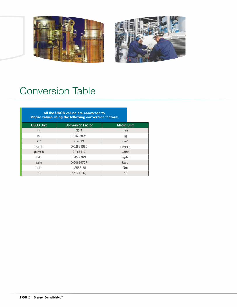
Conversion Table
USCS Unit Conversion Factor Metric Unit
in . 25 .4 mm
lb . 0 .4535924 kg
in2 6 .4516 cm2
ft3/min 0 .02831685 m3/min
gal/min 3 .785412 L/min
lb/hr 0 .4535924 kg/hr
psig 0 .06894757 barg
ft lb 1 .3558181 Nm
°F 5/9 (°F-32) °C
All the USCS values are converted to Metric values using the following conversion factors:
19000 Series Safety Relief Valve | 19000.3
May. 17, 2011
INLET SIZES .5" (12 .7 mm) through 2" (50 .8 mm)
INLET RATINGS ANSI Class 150 through 2500
OUTLET SIZES 1" (25 .4 mm) through 2 .5" (63 .5 mm)
OUTLET RATINGS ANSI Class 150 and 300
ORIFICE SIZES Six sizes: 0 .096 in2 to 0 .567 in2 (0 .619 cm2 to 3 .658 cm2)
TEMPERATURE RANGE -450°F (-267 .8°C) to 1100°F (593 .3°C)
MATERIALS 316 stainless steel trim is standard .
CERTIFICATION
ASME B & PVC, Section II - Material (Applicable as required by ASME B & PVC, Section III or VIII)
ASME B & PVC, Section III, class 2 and 3 (Gas, Vapor, and Liquid Service)
ASME B & PVC, Section VIII (Gas, Vapor, and Liquid Service)
ASME B16 .34 and ASME B16 .5
API 520, 526 and 527
ISO 4126
NACE MR0103-2003 Standard Material Requirements
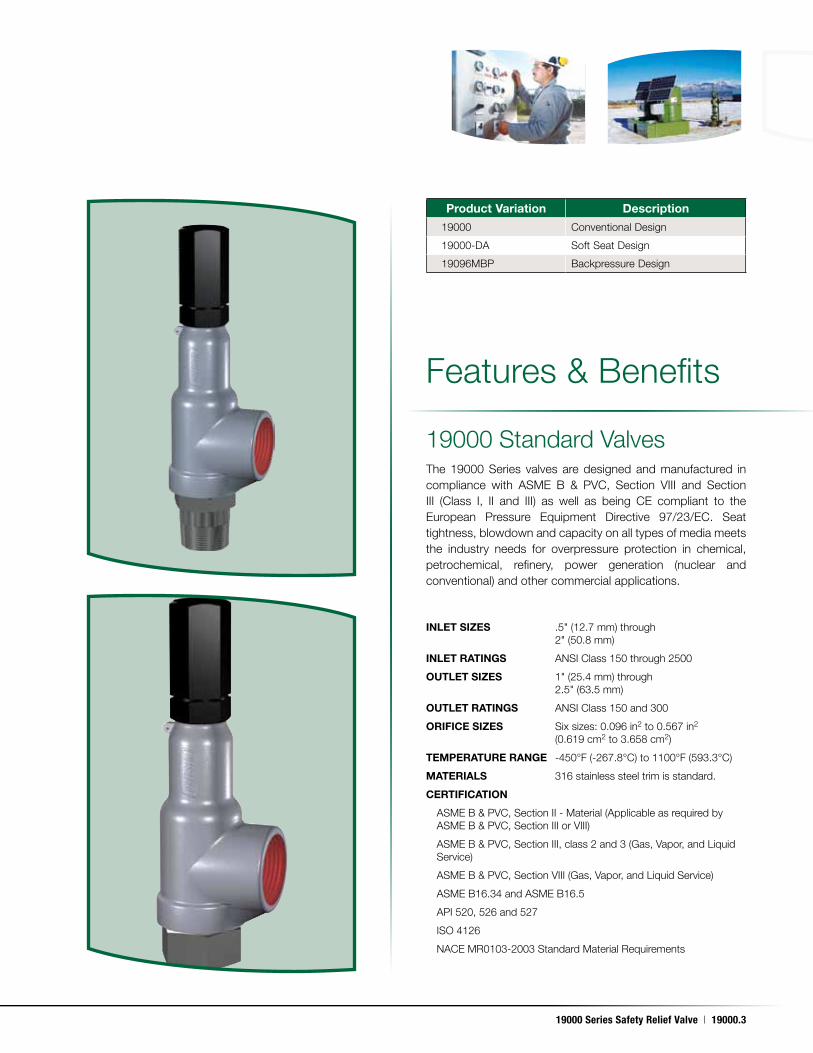
Product Variation Description
19000 Conventional Design
19000-DA Soft Seat Design
19096MBP Backpressure Design
Features & Benefits
The 19000 Series valves are designed and manufactured in compliance with ASME B & PVC, Section VIII and Section III (Class I, II and III) as well as being CE compliant to the European Pressure Equipment Directive 97/23/EC . Seat tightness, blowdown and capacity on all types of media meets the industry needs for overpressure protection in chemical, petrochemical, refinery, power generation (nuclear and conventional) and other commercial applications .
19000 Standard Valves
19000.4 | Dresser Consolidated®
May. 17, 2011
Features & Benefits (Contd .)
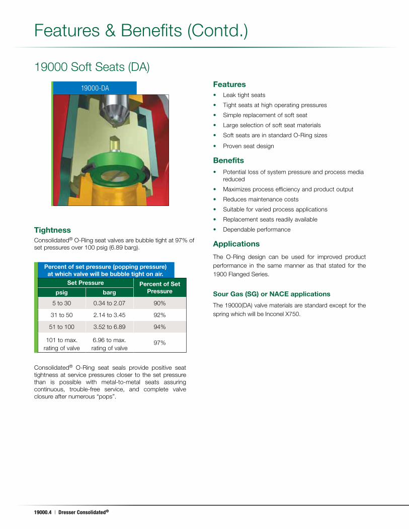
19000 Soft Seats (DA)
TightnessConsolidated® O-Ring seat valves are bubble tight at 97% of set pressures over 100 psig (6 .89 barg) .
Consolidated® O-Ring seat seals provide positive seat tightness at service pressures closer to the set pressure than is possible with metal-to-metal seats assuring continuous, trouble-free service, and complete valve closure after numerous “pops” .
Features• Leak tight seats
• Tight seats at high operating pressures
• Simple replacement of soft seat
• Large selection of soft seat materials
• Soft seats are in standard O-Ring sizes
• Proven seat design
Benefits• Potential loss of system pressure and process media
reduced
• Maximizes process efficiency and product output
• Reduces maintenance costs
• Suitable for varied process applications
• Replacement seats readily available
• Dependable performance
Applications
The O-Ring design can be used for improved product performance in the same manner as that stated for the 1900 Flanged Series .
Sour Gas (SG) or NACE applications
The 19000(DA) valve materials are standard except for the spring which will be Inconel X750 .
Percent of set pressure (popping pressure) at which valve will be bubble tight on air.
19000-DA
Set Pressure Percent of Set Pressurepsig barg
5 to 30 0 .34 to 2 .07 90%
31 to 50 2 .14 to 3 .45 92%
51 to 100 3 .52 to 6 .89 94%
101 to max . rating of valve
6 .96 to max . rating of valve
97%
19000 Series Safety Relief Valve | 19000.5
May. 17, 2011
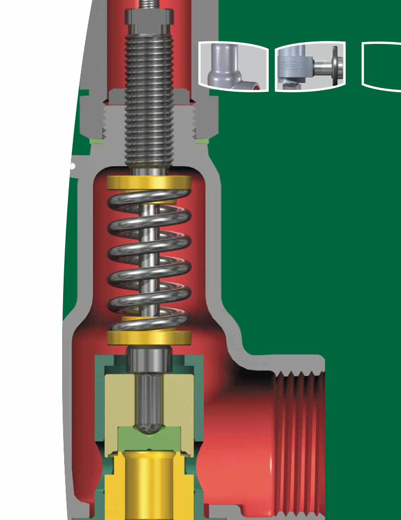
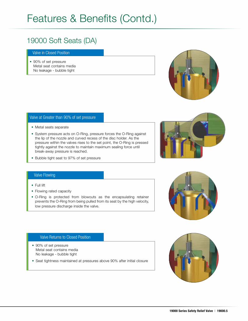
Valve in Closed Position
Features & Benefits (Contd .)
19000 Soft Seats (DA)
• 90% of set pressure Metal seat contains media No leakage - bubble tight
Valve at Greater than 90% of set pressure
Valve Flowing
Valve Returns to Closed Position
• Metal seats separate
• System pressure acts on O-Ring, pressure forces the O-Ring against the lip of the nozzle and curved recess of the disc holder . As the pressure within the valves rises to the set point, the O-Ring is pressed tightly against the nozzle to maintain maximum sealing force until break-away pressure is reached .
• Bubble tight seat to 97% of set pressure
• Full lift
• Flowing rated capacity
• O-Ring is protected from blowouts as the encapsulating retainer prevents the O-Ring from being pulled from its seat by the high velocity, low pressure discharge inside the valve.
• 90% of set pressure Metal seat contains media No leakage - bubble tight
• Seat tightness maintained at pressures above 90% after initial closure
19000.6 | Dresser Consolidated®
May. 17, 2011
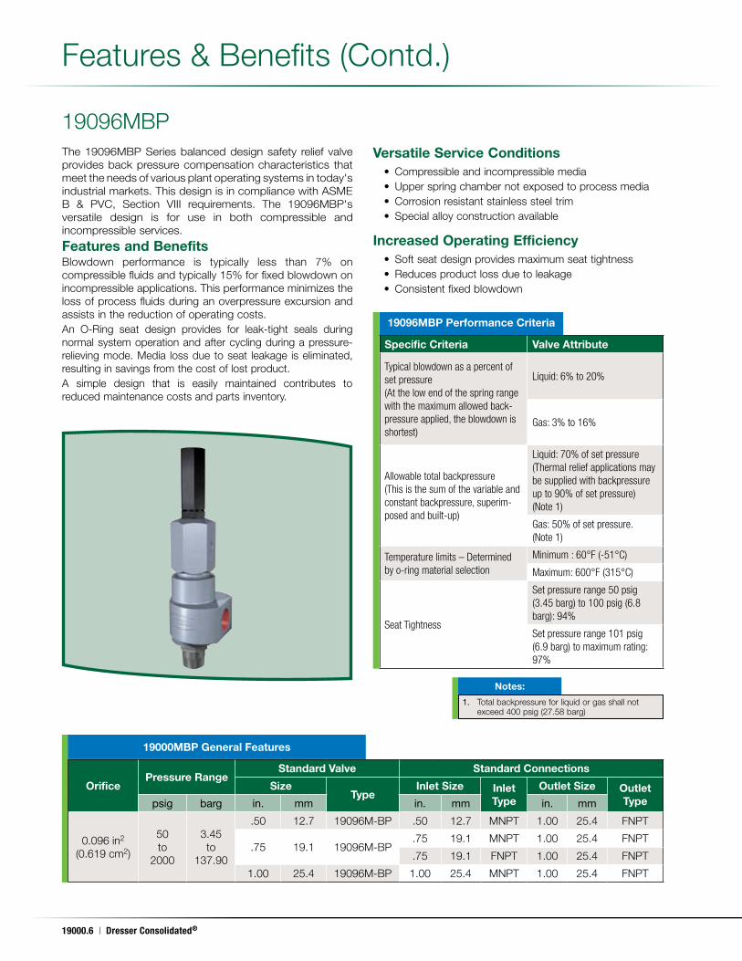
19096MBP
Features & Benefits (Contd .)
The 19096MBP Series balanced design safety relief valve provides back pressure compensation characteristics that meet the needs of various plant operating systems in today's industrial markets . This design is in compliance with ASME B & PVC, Section VIII requirements . The 19096MBP's versatile design is for use in both compressible and incompressible services .
Features and BenefitsBlowdown performance is typically less than 7% on compressible fluids and typically 15% for fixed blowdown on incompressible applications . This performance minimizes the loss of process fluids during an overpressure excursion and assists in the reduction of operating costs .An O-Ring seat design provides for leak-tight seals during normal system operation and after cycling during a pressure-relieving mode . Media loss due to seat leakage is eliminated, resulting in savings from the cost of lost product .A simple design that is easily maintained contributes to reduced maintenance costs and parts inventory .
Versatile Service Conditions • Compressible and incompressible media • Upper spring chamber not exposed to process media • Corrosion resistant stainless steel trim • Special alloy construction available
Increased Operating Efficiency • Soft seat design provides maximum seat tightness • Reduces product loss due to leakage • Consistent fixed blowdown
19096MBP Performance Criteria
1. Total backpressure for liquid or gas shall not exceed 400 psig (27 .58 barg)
Notes:
OrificePressure Range
Standard Valve Standard Connections
SizeType
Inlet Size Inlet Type
Outlet Size Outlet Typepsig barg in. mm in. mm in. mm
0 .096 in2
(0 .619 cm2)
50to
2000
3 .45to
137 .90
.50 12 .7 19096M-BP .50 12 .7 MNPT 1 .00 25 .4 FNPT
.75 19 .1 19096M-BP .75 19 .1 MNPT 1 .00 25 .4 FNPT
.75 19 .1 FNPT 1 .00 25 .4 FNPT
1 .00 25 .4 19096M-BP 1 .00 25 .4 MNPT 1 .00 25 .4 FNPT
19000MBP General Features
Specific Criteria Valve Attribute
Typical blowdown as a percent of set pressure(At the low end of the spring range with the maximum allowed back-pressure applied, the blowdown is shortest)
Liquid: 6% to 20%
Gas: 3% to 16%
Allowable total backpressure (This is the sum of the variable and constant backpressure, superim-posed and built-up)
Liquid: 70% of set pressure(Thermal relief applications may be supplied with backpressure up to 90% of set pressure) (Note 1)
Gas: 50% of set pressure. (Note 1)
Temperature limits – Determined by o-ring material selection
Minimum : 60°F (-51°C)
Maximum: 600°F (315°C)
Seat Tightness
Set pressure range 50 psig (3.45 barg) to 100 psig (6.8 barg): 94%
Set pressure range 101 psig (6.9 barg) to maximum rating: 97%
19000 Series Safety Relief Valve | 19000.7
May. 17, 2011
19000 Standard Valves
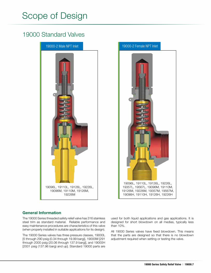
The 19000 Series threaded safety relief valve has 316 stainless steel trim as standard material . Reliable performance and easy maintenance procedures are characteristics of this valve (when properly installed in suitable applications for its design) .
The 19000 Series valves has three pressure classes, 19000L [5 through 290 psig (0 .34 through 19 .99 barg)], 19000M [291 through 2000 psig (20 .06 through 137 .9 barg)], and 19000H [2001 psig (137 .96 barg) and up] . Standard 19000 parts are
used for both liquid applications and gas applications . It is designed for short blowdown on all medias, typically less than 10% .
All 19000 Series valves have fixed blowdown . This means that the parts are designed so that there is no blowdown adjustment required when setting or testing the valve .
Scope of Design
19000-2 Male NPT Inlet 19000-2 Female NPT Inlet
General Information
19096L, 19110L, 19126L, 19226L, 19096M, 19110M, 19126M,
19226M
19096L, 19110L, 19126L, 19226L, 19357L, 19567L, 19096M, 19110M,
19126M, 19226M, 19357M, 19567M, 19096H, 19110H, 19126H, 19226H
19000.8 | Dresser Consolidated®
May. 17, 2011
19000 Standard Valves
19000MBP
Scope of Design (Contd .)
The standard 19000 valve has component materials selected which comply with NACE MR-01-75 requirements (except the valve spring) . To fully comply with MR-01-75, utilize the standard valve and specify an Inconel X750 spring . When service temperature exceeds 250°F (121°C) an Inconel X750 disc will be the standard component material meeting
the requirements of MR-01-75 . Under 250°F (121°C) the standard component material for the disc is 316SS .
The Inconel X750 disc, Inconel X750 disc holder, Stellite® faced base and Inconel X750 spindle used in high pressure valves will meet the requirements of MR-01-75 when supplied with an Inconel X750 spring .
Design Options
a. O-Ring seat seal valves All 19000 Series valves are available with an O-Ring seat
seal, as a design option . This optional design provides a bubble tightness in excess of 97% of the valve set pressure, in order to meet application requirements beyond the normal capabilities of metal to metal seat valves . 19000 Series valves with the O-Ring seat seal option are identified by the suffix DA (e .g ., 1-19096L-DA) .
b. Lifting Levers, Caps and Gags All 19000 Series valves are designed so that field
conversion from the standard screwed cap to a plain lifting lever cap, or to a packed lifting lever cap (or vice versa) does not require valve assembly during resetting . The lifting lever option is designed to open the valve at 75% of the valve set pressure, in compliance with ASME B & PVC, Section VIII . Further, all available 19000 Series valve caps may be equipped with a gag, upon customer request .
c. Inlet/Outlet Connections All 19000 Series valves can be provided by Consolidated
with flanges, threaded or socket weld inlet/outlet connections upon customer request .
This product is normally supplied with threaded inlet and outlet connections . Socket weld or flanged end connections are available as well .
Product type designations change depending on connection sizes, orifice sizes, pressure range, and whether connections are male or female .
Unless otherwise specified, the valve is always supplied with a screwed cap . The exception to this would be where ASME requires levers for steam, air and water service over 140°F (60°C) .
Springs of precipitation hardened stainless steel are specified for -75°F to 800°F (-59°C to 426 .6°C) and the valves carry a “c” suffix in that case . Inconel springs are used for temperatures 801 to 1100°F (427 .2 to 593 .3°C) and the valve carries a “t” suffix .
When selecting valves for back pressure applications, the following limits apply .
• Constant back pressure: 400 psig (27 .58 barg) max .
• Variable back pressure (superimposed or built-up):400 psig (27 .58 barg) or 10% of set pressure whichever is smaller .
Product variations consist of:
• 19000SG - Sour Gas Trim
• 19000DA - Soft Seat
• 19000MBP - Back Pressure Compensation
Product material variations include:
• 316 Stainless Steel
• Monel
• Hastelloy
• Alloy 20
19000SG (Sour Gas)
1 Pressure/Temperature ratings may vary from those for standard valves when other than standard materials are selected . Consult factory for assistance .
Notes:
Scope of Design
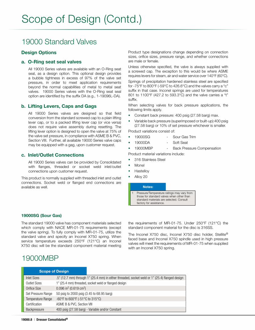
Inlet Sizes .5” (12.7 mm) through 1” (25.4 mm) in either threaded, socket weld or 1” (25.4) flanged designOutlet Sizes 1” (25.4 mm) threaded, socket weld or flanged designOrifice Size 0.096 in2 (0.619 cm2)Set Pressure Range 50 psig to 2000 psig (3.45 to 68.95 barg)Temperature Range -60°F to 600°F (-51°C to 315°C)Certification ASME B & PVC, Section VIIIBackpressure 400 psig (27.58 barg) - Variable and/or Constant
19000 Series Safety Relief Valve | 19000.9
May. 17, 2011
Scope of Design (Contd .)
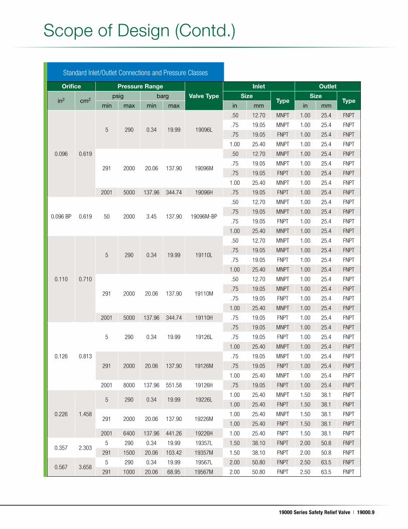
Orifice Pressure Range
Valve Type
Inlet Outlet
in2 cm2psig barg Size
TypeSize
Typemin max min max in mm in mm
0.096 0.619
5 290 0.34 19.99 19096L
.50 12.70 MNPT 1.00 25.4 FNPT
.75 19.05 MNPT 1.00 25.4 FNPT
.75 19.05 FNPT 1.00 25.4 FNPT
1.00 25.40 MNPT 1.00 25.4 FNPT
291 2000 20.06 137.90 19096M
.50 12.70 MNPT 1.00 25.4 FNPT
.75 19.05 MNPT 1.00 25.4 FNPT
.75 19.05 FNPT 1.00 25.4 FNPT
1.00 25.40 MNPT 1.00 25.4 FNPT
2001 5000 137.96 344.74 19096H .75 19.05 FNPT 1.00 25.4 FNPT
0.096 BP 0.619 50 2000 3.45 137.90 19096M-BP
.50 12.70 MNPT 1.00 25.4 FNPT
.75 19.05 MNPT 1.00 25.4 FNPT
.75 19.05 FNPT 1.00 25.4 FNPT
1.00 25.40 MNPT 1.00 25.4 FNPT
0.110 0.710
5 290 0.34 19.99 19110L
.50 12.70 MNPT 1.00 25.4 FNPT
.75 19.05 MNPT 1.00 25.4 FNPT
.75 19.05 FNPT 1.00 25.4 FNPT
1.00 25.40 MNPT 1.00 25.4 FNPT
291 2000 20.06 137.90 19110M
.50 12.70 MNPT 1.00 25.4 FNPT
.75 19.05 MNPT 1.00 25.4 FNPT
.75 19.05 FNPT 1.00 25.4 FNPT
1.00 25.40 MNPT 1.00 25.4 FNPT
2001 5000 137.96 344.74 19110H .75 19.05 FNPT 1.00 25.4 FNPT
0.126 0.813
5 290 0.34 19.99 19126L
.75 19.05 MNPT 1.00 25.4 FNPT
.75 19.05 FNPT 1.00 25.4 FNPT
1.00 25.40 MNPT 1.00 25.4 FNPT
291 2000 20.06 137.90 19126M
.75 19.05 MNPT 1.00 25.4 FNPT
.75 19.05 FNPT 1.00 25.4 FNPT
1.00 25.40 MNPT 1.00 25.4 FNPT
2001 8000 137.96 551.58 19126H .75 19.05 FNPT 1.00 25.4 FNPT
0.226 1.458
5 290 0.34 19.99 19226L1.00 25.40 MNPT 1.50 38.1 FNPT
1.00 25.40 FNPT 1.50 38.1 FNPT
291 2000 20.06 137.90 19226M1.00 25.40 MNPT 1.50 38.1 FNPT
1.00 25.40 FNPT 1.50 38.1 FNPT
2001 6400 137.96 441.26 19226H 1.00 25.40 FNPT 1.50 38.1 FNPT
0.357 2.3035 290 0.34 19.99 19357L 1.50 38.10 FNPT 2.00 50.8 FNPT
291 1500 20.06 103.42 19357M 1.50 38.10 FNPT 2.00 50.8 FNPT
0.567 3.6585 290 0.34 19.99 19567L 2.00 50.80 FNPT 2.50 63.5 FNPT
291 1000 20.06 68.95 19567M 2.00 50.80 FNPT 2.50 63.5 FNPT
Standard Inlet/Outlet Connections and Pressure Classes
19000.10 | Dresser Consolidated®
May. 17, 2011
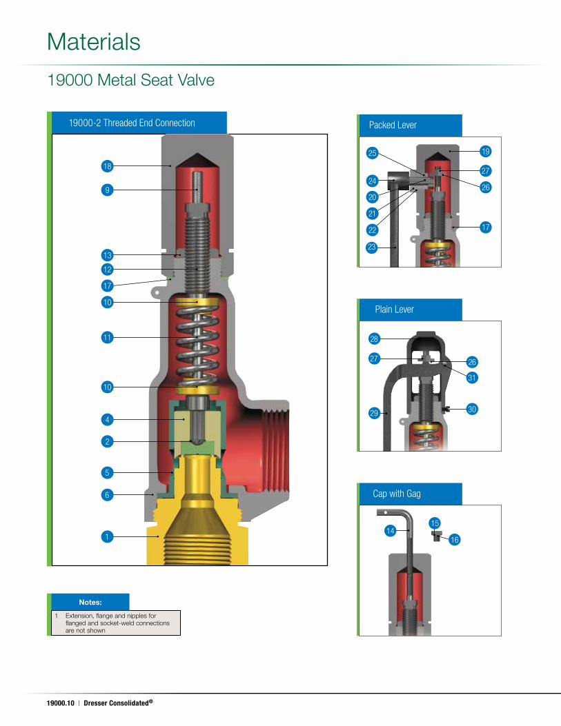
19000-2 Threaded End Connection
19000 Metal Seat Valve
Materials
Packed Lever
25
24
20
21
22
19
27
26
17
23
Plain Lever
26
31
30
28
27
29
Cap with Gag
16
1514
1 Extension, flange and nipples for flanged and socket-weld connections are not shown
Notes:
18
9
13
12
10
11
10
4
2
5
6
1
17
19000 Series Safety Relief Valve | 19000.11
May. 17, 2011
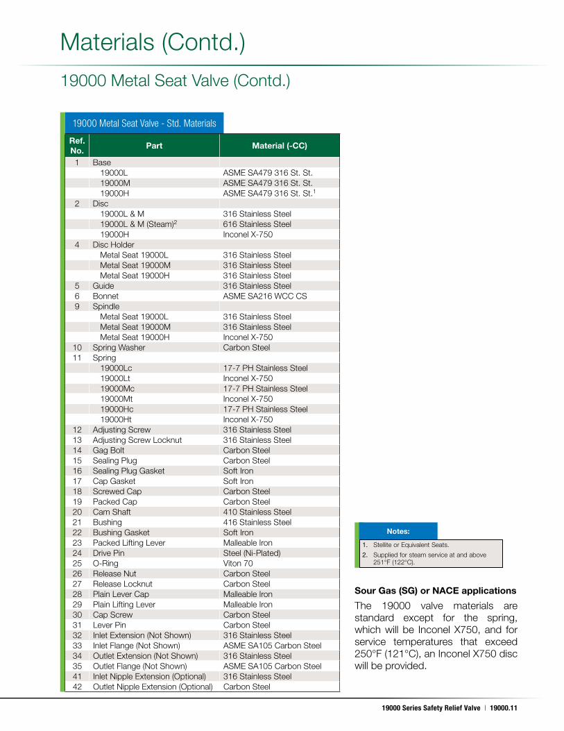
19000 Metal Seat Valve - Std. Materials
19000 Metal Seat Valve (Contd .)
Sour Gas (SG) or NACE applications
The 19000 valve materials are standard except for the spring, which will be Inconel X750, and for service temperatures that exceed 250°F (121°C), an Inconel X750 disc will be provided .
Materials (Contd .)
Ref. No.
Part Material (-CC)
1 Base19000L ASME SA479 316 St . St .19000M ASME SA479 316 St . St .19000H ASME SA479 316 St . St .1
2 Disc19000L & M 316 Stainless Steel19000L & M (Steam)2 616 Stainless Steel19000H Inconel X-750
4 Disc HolderMetal Seat 19000L 316 Stainless SteelMetal Seat 19000M 316 Stainless SteelMetal Seat 19000H 316 Stainless Steel
5 Guide 316 Stainless Steel6 Bonnet ASME SA216 WCC CS9 Spindle
Metal Seat 19000L 316 Stainless SteelMetal Seat 19000M 316 Stainless SteelMetal Seat 19000H Inconel X-750
10 Spring Washer Carbon Steel11 Spring
19000Lc 17-7 PH Stainless Steel19000Lt Inconel X-75019000Mc 17-7 PH Stainless Steel19000Mt Inconel X-75019000Hc 17-7 PH Stainless Steel19000Ht Inconel X-750
12 Adjusting Screw 316 Stainless Steel13 Adjusting Screw Locknut 316 Stainless Steel14 Gag Bolt Carbon Steel15 Sealing Plug Carbon Steel16 Sealing Plug Gasket Soft Iron17 Cap Gasket Soft Iron18 Screwed Cap Carbon Steel19 Packed Cap Carbon Steel20 Cam Shaft 410 Stainless Steel21 Bushing 416 Stainless Steel22 Bushing Gasket Soft Iron23 Packed Lifting Lever Malleable Iron24 Drive Pin Steel (Ni-Plated)25 O-Ring Viton 7026 Release Nut Carbon Steel27 Release Locknut Carbon Steel28 Plain Lever Cap Malleable Iron29 Plain Lifting Lever Malleable Iron30 Cap Screw Carbon Steel31 Lever Pin Carbon Steel32 Inlet Extension (Not Shown) 316 Stainless Steel33 Inlet Flange (Not Shown) ASME SA105 Carbon Steel34 Outlet Extension (Not Shown) 316 Stainless Steel35 Outlet Flange (Not Shown) ASME SA105 Carbon Steel41 Inlet Nipple Extension (Optional) 316 Stainless Steel42 Outlet Nipple Extension (Optional) Carbon Steel
1. Stellite or Equivalent Seats .
2. Supplied for steam service at and above 251°F (122°C) .
Notes:
19000.12 | Dresser Consolidated®
May. 17, 2011
Plain Lever
28
26
30
29
3127
Cap with Gag
1415
16
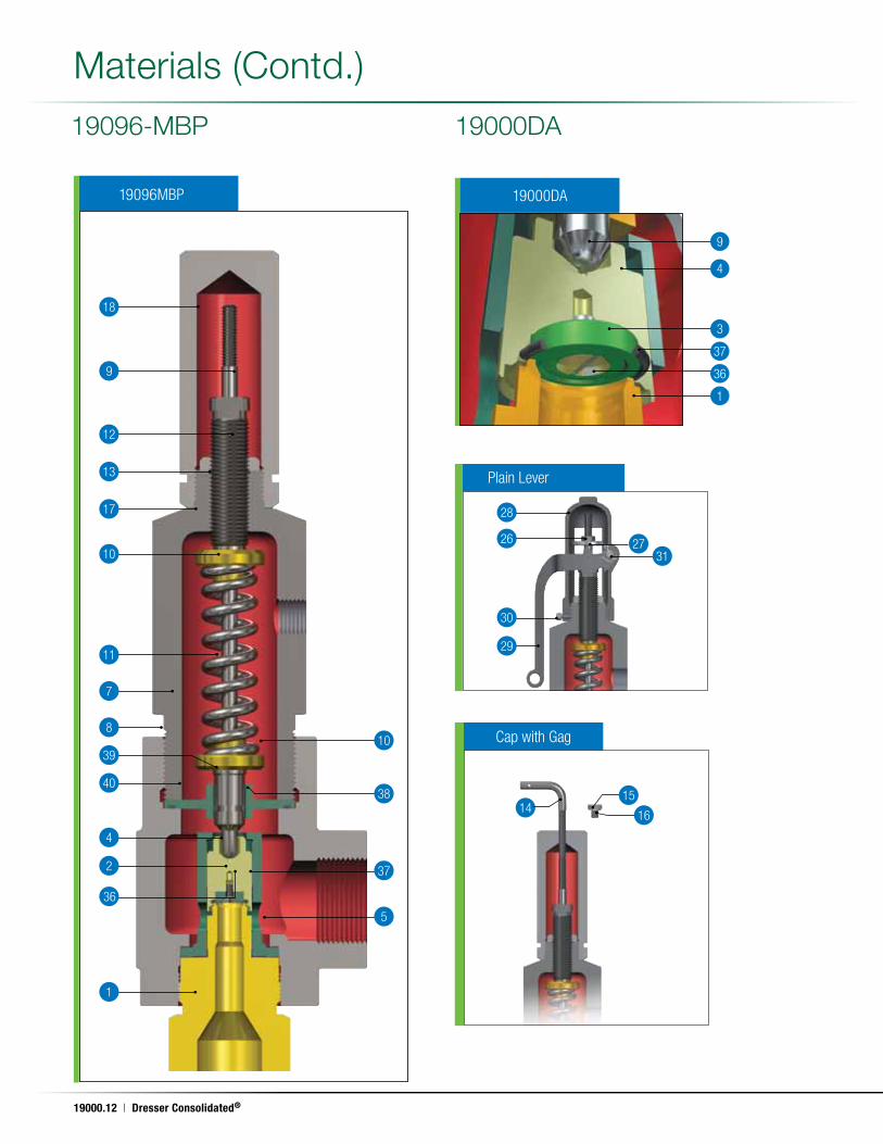
19000DA19096-MBP
Materials (Contd .)
9
18
17
10
4
2
36
10
38
37
5
1
8
39
40
7
11
12
13
19096MBP 19000DA
37
1
4
9
3
36
19000 Series Safety Relief Valve | 19000.13
May. 17, 2011
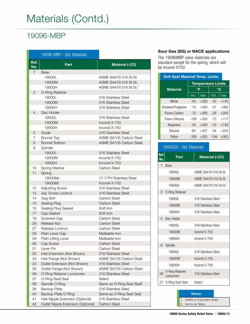
Sour Gas (SG) or NACE applications
The 19096MBP valve materials are standard except for the spring, which will be Inconel X750.
19096-MBP
Materials (Contd .)
19096-MBP - Std. Materials
19000DA - Std. Materials
Ref. No.
Part Material (-CC)
1 Base19000L ASME SA479 316 St .St .19000M ASME SA479 316 St .St .19000H ASME SA479 316 St .St .1
3 O-Ring Retainer19000L 316 Stainless Steel19000M 316 Stainless Steel19000H 316 Stainless Steel
4 Disc Holder19000L 316 Stainless Steel19000M Inconel X-75019000H Inconel X-750
5 Guide 316 Stainless Steel7 Bonnet Top ASME SA105 Carbon Steel8 Bonnet Bottom ASME SA105 Carbon Steel9 Spindle
19000L 316 Stainless Steel19000M Inconel X-75019000H Inconel X-750
10 Spring Washer Carbon Steel11 Spring
19000Mc 17-7 PH Stainless Steel19000Mt Inconel X-750
12 Adjusting Screw 316 Stainless Steel13 Adj . Screw Locknut 316 Stainless Steel14 Gag Bolt Carbon Steel15 Sealing Plug Carbon Steel16 Sealing Plug Gasket Soft Iron17 Cap Gasket Soft Iron18 Screwed Cap Carbon Steel26 Release Nut Carbon Steel27 Release Locknut Carbon Steel28 Plain Lever Cap Malleable Iron29 Plain Lifting Lever Malleable Iron30 Cap Screw Carbon Steel31 Lever Pin Carbon Steel32 Inlet Extension (Not Shown) 316 Stainless Steel33 Inlet Flange (Not Shown) ASME SA105 Carbon Steel34 Outlet Extension (Not Shown) 316 Stainless Steel35 Outlet Flange (Not Shown) ASME SA105 Carbon Steel36 O-Ring Retainer Lockscrew 316 Stainless Steel37 O-Ring Seat Seal Select38 Spindle O-Ring Same as O-Ring Seat Seal2
39 Backup Plate 316 Stainless Steel40 Backup Plate O-Ring Same as O-Ring Seat Seal41 Inlet Nipple Extension (Optional) 316 Stainless Steel42 Outlet Nipple Extension (Optional) Carbon Steel
Ref. No.
Part Material (-CC)
1 Base
19000L ASME SA479 316 St.St.
19000M ASME SA479 316 St.St.
19000H ASME SA479 316 St.St.1
3 O-Ring Retainer
19000L 316 Stainless Steel
19000M 316 Stainless Steel
19000H 316 Stainless Steel
4 Disc Holder
19000L 316 Stainless Steel
19000M Inconel X-750
19000H Inconel X-750
9 Spindle
19000L 316 Stainless Steel
19000M Inconel X-750
19000H Inconel X-750
36O-Ring Retainer Lockscrew
316 Stainless Steel
37 O-Ring Seat Seal Select
1. Stellite or Equivalent Seats .
2. Not to be Teflon .
Notes:
Soft Seat Material Temp. Limits
Material
Temperature Limits
°F °C
min. max. min. max.
Nitrile -45 +300 -43 +149
Ethylene/Propylene -70 +500 -57 +260
Fluoro-Carbon -15 +400 -26 +204
Fluoro-Silicone -100 +350 -73 +177
Neoprene -45 +300 -43 +149
Silicone -65 +437 -54 +225
Teflon -300 +505 -184 +263
19000.14 | Dresser Consolidated®
May. 17, 2011
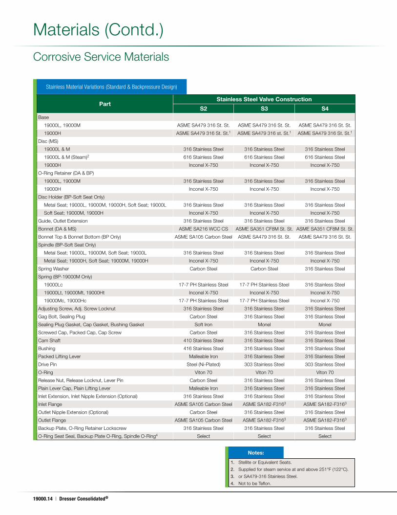
Stainless Material Variations (Standard & Backpressure Design)
Corrosive Service Materials
Materials (Contd .)
Part Stainless Steel Valve Construction
S2 S3 S4Base
19000L, 19000M ASME SA479 316 St . St . ASME SA479 316 St . St . ASME SA479 316 St . St .
19000H ASME SA479 316 St . St .1 ASME SA479 316 st . St .1 ASME SA479 316 St . St .1
Disc (MS)
19000L & M 316 Stainless Steel 316 Stainless Steel 316 Stainless Steel
19000L & M (Steam)2 616 Stainless Steel 616 Stainless Steel 616 Stainless Steel
19000H Inconel X-750 Inconel X-750 Inconel X-750
O-Ring Retainer (DA & BP)
19000L, 19000M 316 Stainless Steel 316 Stainless Steel 316 Stainless Steel
19000H Inconel X-750 Inconel X-750 Inconel X-750
Disc Holder (BP-Soft Seat Only)
Metal Seat; 19000L, 19000M, 19000H, Soft Seat; 19000L 316 Stainless Steel 316 Stainless Steel 316 Stainless Steel
Soft Seat; 19000M, 19000H Inconel X-750 Inconel X-750 Inconel X-750
Guide, Outlet Extension 316 Stainless Steel 316 Stainless Steel 316 Stainless Steel
Bonnet (DA & MS) ASME SA216 WCC CS ASME SA351 CF8M St . St . ASME SA351 CF8M St . St .
Bonnet Top & Bonnet Bottom (BP Only) ASME SA105 Carbon Steel ASME SA479 316 St . St . ASME SA479 316 St . St .
Spindle (BP-Soft Seat Only)
Metal Seat; 19000L, 19000M, Soft Seat; 19000L 316 Stainless Steel 316 Stainless Steel 316 Stainless Steel
Metal Seat; 19000H, Soft Seat; 19000M, 19000H Inconel X-750 Inconel X-750 Inconel X-750
Spring Washer Carbon Steel Carbon Steel 316 Stainless Steel
Spring (BP-19000M Only)
19000Lc 17-7 PH Stainless Steel 17-7 PH Stainless Steel 316 Stainless Steel
19000Lt, 19000Mt, 19000Ht Inconel X-750 Inconel X-750 Inconel X-750
19000Mc, 19000Hc 17-7 PH Stainless Steel 17-7 PH Stainless Steel Inconel X-750
Adjusting Screw, Adj . Screw Locknut 316 Stainless Steel 316 Stainless Steel 316 Stainless Steel
Gag Bolt, Sealing Plug Carbon Steel 316 Stainless Steel 316 Stainless Steel
Sealing Plug Gasket, Cap Gasket, Bushing Gasket Soft Iron Monel Monel
Screwed Cap, Packed Cap, Cap Screw Carbon Steel 316 Stainless Steel 316 Stainless Steel
Cam Shaft 410 Stainless Steel 316 Stainless Steel 316 Stainless Steel
Bushing 416 Stainless Steel 316 Stainless Steel 316 Stainless Steel
Packed Lifting Lever Malleable Iron 316 Stainless Steel 316 Stainless Steel
Drive Pin Steel (Ni-Plated) 303 Stainless Steel 303 Stainless Steel
O-Ring Viton 70 Viton 70 Viton 70
Release Nut, Release Locknut, Lever Pin Carbon Steel 316 Stainless Steel 316 Stainless Steel
Plain Lever Cap, Plain Lifting Lever Malleable Iron 316 Stainless Steel 316 Stainless Steel
Inlet Extension, Inlet Nipple Extension (Optional) 316 Stainless Steel 316 Stainless Steel 316 Stainless Steel
Inlet Flange ASME SA105 Carbon Steel ASME SA182-F3163 ASME SA182-F3163
Outlet Nipple Extension (Optional) Carbon Steel 316 Stainless Steel 316 Stainless Steel
Outlet Flange ASME SA105 Carbon Steel ASME SA182-F3163 ASME SA182-F3163
Backup Plate, O-Ring Retainer Lockscrew 316 Stainless Steel 316 Stainless Steel 316 Stainless Steel
O-Ring Seat Seal, Backup Plate O-Ring, Spindle O-Ring4 Select Select Select
1. Stellite or Equivalent Seats .
2. Supplied for steam service at and above 251°F (122°C) .
3. or SA479-316 Stainless Steel .
4. Not to be Teflon .
Notes:
19000 Series Safety Relief Valve | 19000.15
May. 17, 2011
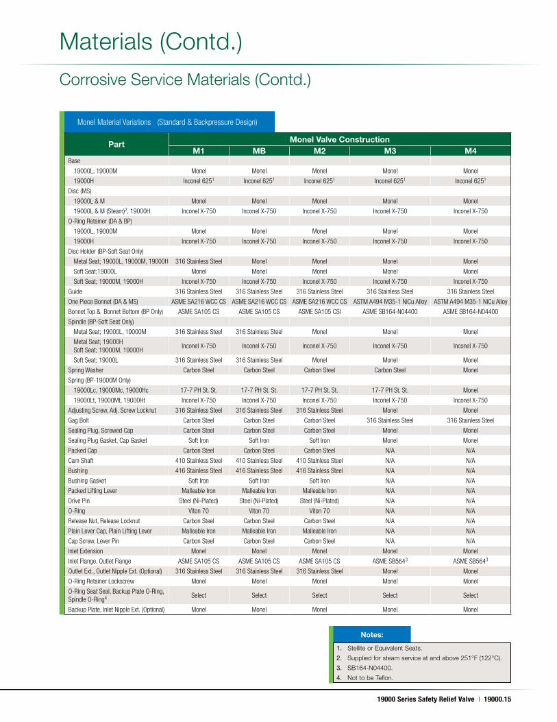
Part Monel Valve ConstructionM1 MB M2 M3 M4
Base
19000L, 19000M Monel Monel Monel Monel Monel
19000H Inconel 6251 Inconel 6251 Inconel 6251 Inconel 6251 Inconel 6251
Disc (MS)
19000L & M Monel Monel Monel Monel Monel
19000L & M (Steam)2, 19000H Inconel X-750 Inconel X-750 Inconel X-750 Inconel X-750 Inconel X-750
O-Ring Retainer (DA & BP)
19000L, 19000M Monel Monel Monel Monel Monel
19000H Inconel X-750 Inconel X-750 Inconel X-750 Inconel X-750 Inconel X-750
Disc Holder (BP-Soft Seat Only)
Metal Seat; 19000L, 19000M, 19000H 316 Stainless Steel Monel Monel Monel Monel
Soft Seat;19000L Monel Monel Monel Monel Monel
Soft Seat; 19000M, 19000H Inconel X-750 Inconel X-750 Inconel X-750 Inconel X-750 Inconel X-750
Guide 316 Stainless Steel 316 Stainless Steel 316 Stainless Steel 316 Stainless Steel 316 Stainless Steel
One Piece Bonnet (DA & MS) ASME SA216 WCC CS ASME SA216 WCC CS ASME SA216 WCC CS ASTM A494 M35-1 NiCu Alloy ASTM A494 M35-1 NiCu Alloy
Bonnet Top & Bonnet Bottom (BP Only) ASME SA105 CS ASME SA105 CS ASME SA105 CSl ASME SB164-N04400 ASME SB164-N04400
Spindle (BP-Soft Seat Only)
Metal Seat; 19000L, 19000M 316 Stainless Steel 316 Stainless Steel Monel Monel Monel
Metal Seat; 19000H Soft Seat; 19000M, 19000H
Inconel X-750 Inconel X-750 Inconel X-750 Inconel X-750 Inconel X-750
Soft Seat; 19000L 316 Stainless Steel 316 Stainless Steel Monel Monel Monel
Spring Washer Carbon Steel Carbon Steel Carbon Steel Carbon Steel Monel
Spring (BP-19000M Only)
19000Lc, 19000Mc, 19000Hc 17-7 PH St. St. 17-7 PH St. St. 17-7 PH St. St. 17-7 PH St. St. Monel
19000Lt, 19000Mt, 19000Ht Inconel X-750 Inconel X-750 Inconel X-750 Inconel X-750 Inconel X-750
Adjusting Screw, Adj. Screw Locknut 316 Stainless Steel 316 Stainless Steel 316 Stainless Steel Monel Monel
Gag Bolt Carbon Steel Carbon Steel Carbon Steel 316 Stainless Steel 316 Stainless Steel
Sealing Plug, Screwed Cap Carbon Steel Carbon Steel Carbon Steel Monel Monel
Sealing Plug Gasket, Cap Gasket Soft Iron Soft Iron Soft Iron Monel Monel
Packed Cap Carbon Steel Carbon Steel Carbon Steel N/A N/A
Cam Shaft 410 Stainless Steel 410 Stainless Steel 410 Stainless Steel N/A N/A
Bushing 416 Stainless Steel 416 Stainless Steel 416 Stainless Steel N/A N/A
Bushing Gasket Soft Iron Soft Iron Soft Iron N/A N/A
Packed Lifting Lever Malleable Iron Malleable Iron Malleable Iron N/A N/A
Drive Pin Steel (Ni-Plated) Steel (Ni-Plated) Steel (Ni-Plated) N/A N/A
O-Ring Viton 70 Viton 70 Viton 70 N/A N/A
Release Nut, Release Locknut Carbon Steel Carbon Steel Carbon Steel N/A N/A
Plain Lever Cap, Plain Lifting Lever Malleable Iron Malleable Iron Malleable Iron N/A N/A
Cap Screw, Lever Pin Carbon Steel Carbon Steel Carbon Steel N/A N/A
Inlet Extension Monel Monel Monel Monel Monel
Inlet Flange, Outlet Flange ASME SA105 CS ASME SA105 CS ASME SA105 CS ASME SB5643 ASME SB5643
Outlet Ext., Outlet Nipple Ext. (Optional) 316 Stainless Steel 316 Stainless Steel 316 Stainless Steel Monel Monel
O-Ring Retainer Lockscrew Monel Monel Monel Monel Monel
O-Ring Seat Seal, Backup Plate O-Ring, Spindle O-Ring4 Select Select Select Select Select
Backup Plate, Inlet Nipple Ext. (Optional) Monel Monel Monel Monel Monel
Monel Material Variations (Standard & Backpressure Design)
Corrosive Service Materials (Contd .)
Materials (Contd .)
1. Stellite or Equivalent Seats .
2. Supplied for steam service at and above 251°F (122°C) .
3. SB164-N04400 .
4. Not to be Teflon .
Notes:
19000.16 | Dresser Consolidated®
May. 17, 2011
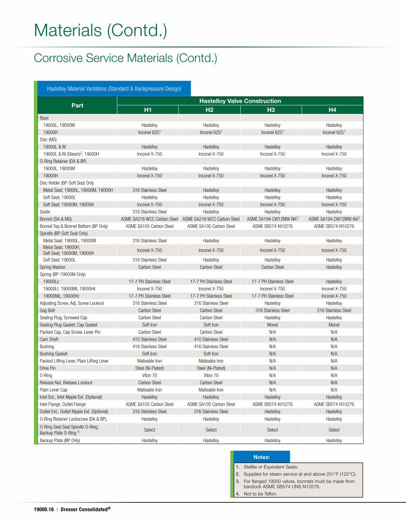
Hastelloy Material Variations (Standard & Backpressure Design)
Corrosive Service Materials (Contd .)
Materials (Contd .)
PartHastelloy Valve Construction
H1 H2 H3 H4Base
19000L, 19000M Hastelloy Hastelloy Hastelloy Hastelloy
19000H Inconel 6251 Inconel 6251 Inconel 6251 Inconel 6251
Disc (MS)
19000L & M Hastelloy Hastelloy Hastelloy Hastelloy
19000L & M (Steam)2, 19000H Inconel X-750 Inconel X-750 Inconel X-750 Inconel X-750
O-Ring Retainer (DA & BP)
19000L, 19000M Hastelloy Hastelloy Hastelloy Hastelloy
19000H Inconel X-750 Inconel X-750 Inconel X-750 Inconel X-750
Disc Holder (BP-Soft Seat Only
Metal Seat; 19000L, 19000M, 19000H 316 Stainless Steel Hastelloy Hastelloy Hastelloy
Soft Seat; 19000L Hastelloy Hastelloy Hastelloy Hastelloy
Soft Seat; 19000M, 19000H Inconel X-750 Inconel X-750 Inconel X-750 Inconel X-750
Guide 316 Stainless Steel Hastelloy Hastelloy Hastelloy
Bonnet (DA & MS) ASME SA216 WCC Carbon Steel ASME SA216 WCC Carbon Steel ASME SA194 CW12MW NA3 ASME SA194 CW12MW NA3
Bonnet Top & Bonnet Bottom (BP Only) ASME SA105 Carbon Steel ASME SA105 Carbon Steel ASME SB574-N10276 ASME SB574-N10276
Spindle (BP-Soft Seat Only)
Metal Seat; 19000L, 19000M 316 Stainless Steel Hastelloy Hastelloy HastelloyMetal Seat; 19000H, Soft Seat; 19000M, 19000H
Inconel X-750 Inconel X-750 Inconel X-750 Inconel X-750
Soft Seat; 19000L 316 Stainless Steel Hastelloy Hastelloy Hastelloy
Spring Washer Carbon Steel Carbon Steel Carbon Steel Hastelloy
Spring (BP-19000M Only)
19000Lc 17-7 PH Stainless Steel 17-7 PH Stainless Steel 17-7 PH Stainless Steel Hastelloy
19000Lt, 19000Mt, 19000Ht Inconel X-750 Inconel X-750 Inconel X-750 Inconel X-750
19000Mc, 19000Hc 17-7 PH Stainless Steel 17-7 PH Stainless Steel 17-7 PH Stainless Steel Inconel X-750
Adjusting Screw, Adj. Screw Locknut 316 Stainless Steel 316 Stainless Steel Hastelloy Hastelloy
Gag Bolt Carbon Steel Carbon Steel 316 Stainless Steel 316 Stainless Steel
Sealing Plug, Screwed Cap Carbon Steel Carbon Steel Hastelloy Hastelloy
Sealing Plug Gasket, Cap Gasket Soft Iron Soft Iron Monel Monel
Packed Cap, Cap Screw, Lever Pin Carbon Steel Carbon Steel N/A N/A
Cam Shaft 410 Stainless Steel 410 Stainless Steel N/A N/A
Bushing 416 Stainless Steel 416 Stainless Steel N/A N/A
Bushing Gasket Soft Iron Soft Iron N/A N/A
Packed Lifting Lever, Plain Lifting Lever Malleable Iron Malleable Iron N/A N/A
Drive Pin Steel (Ni-Plated) Steel (Ni-Plated) N/A N/A
O-Ring Viton 70 Viton 70 N/A N/A
Release Nut, Release Locknut Carbon Steel Carbon Steel N/A N/A
Plain Lever Cap Malleable Iron Malleable Iron N/A N/A
Inlet Ext., Inlet Nipple Ext. (Optional) Hastelloy Hastelloy Hastelloy Hastelloy
Inlet Flange, Outlet Flange ASME SA105 Carbon Steel ASME SA105 Carbon Steel ASME SB574-N10276 ASME SB574-N10276
Outlet Ext., Outlet Nipple Ext. (Optional) 316 Stainless Steel 316 Stainless Steel Hastelloy Hastelloy
O-Ring Retainer Lockscrew (DA & BP), Hastelloy Hastelloy Hastelloy Hastelloy
O-Ring Seat Seal Spindle O-Ring, Backup Plate O-Ring 4
Select Select Select Select
Backup Plate (BP Only) Hastelloy Hastelloy Hastelloy Hastelloy
1. Stellite or Equivalent Seats .
2. Supplied for steam service at and above 251°F (122°C) .
3. For flanged 19000 valves, bonnets must be made from barstock ASME SB574 UNS N10276 .
4. Not to be Teflon .
Notes:
19000 Series Safety Relief Valve | 19000.17
May. 17, 2011
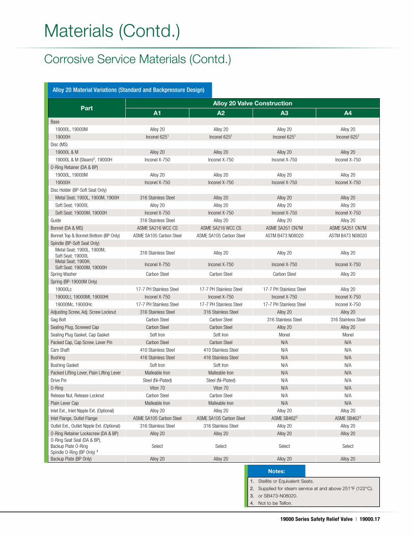
PartAlloy 20 Valve Construction
A1 A2 A3 A4Base
19000L, 19000M Alloy 20 Alloy 20 Alloy 20 Alloy 20
19000H Inconel 6251 Inconel 6251 Inconel 6251 Inconel 6251
Disc (MS)
19000L & M Alloy 20 Alloy 20 Alloy 20 Alloy 20
19000L & M (Steam)2, 19000H Inconel X-750 Inconel X-750 Inconel X-750 Inconel X-750
O-Ring Retainer (DA & BP)
19000L, 19000M Alloy 20 Alloy 20 Alloy 20 Alloy 20
19000H Inconel X-750 Inconel X-750 Inconel X-750 Inconel X-750
Disc Holder (BP-Soft Seat Only)
Metal Seat; 1900L, 1900M, 1900H 316 Stainless Steel Alloy 20 Alloy 20 Alloy 20
Soft Seat; 19000L Alloy 20 Alloy 20 Alloy 20 Alloy 20
Soft Seat; 19000M, 19000H Inconel X-750 Inconel X-750 Inconel X-750 Inconel X-750
Guide 316 Stainless Steel Alloy 20 Alloy 20 Alloy 20
Bonnet (DA & MS) ASME SA216 WCC CS ASME SA216 WCC CS ASME SA351 CN7M ASME SA351 CN7M
Bonnet Top & Bonnet Bottom (BP Only) ASME SA105 Carbon Steel ASME SA105 Carbon Steel ASTM B473 N08020 ASTM B473 N08020
Spindle (BP-Soft Seat Only)Metal Seat; 1900L, 1900M, Soft Seat; 19000L
316 Stainless Steel Alloy 20 Alloy 20 Alloy 20
Metal Seat; 1900H, Soft Seat; 19000M, 19000H
Inconel X-750 Inconel X-750 Inconel X-750 Inconel X-750
Spring Washer Carbon Steel Carbon Steel Carbon Steel Alloy 20
Spring (BP-19000M Only)
19000Lc 17-7 PH Stainless Steel 17-7 PH Stainless Steel 17-7 PH Stainless Steel Alloy 20
19000Lt, 19000Mt, 19000Ht Inconel X-750 Inconel X-750 Inconel X-750 Inconel X-750
19000Mc, 19000Hc 17-7 PH Stainless Steel 17-7 PH Stainless Steel 17-7 PH Stainless Steel Inconel X-750
Adjusting Screw, Adj. Screw Locknut 316 Stainless Steel 316 Stainless Steel Alloy 20 Alloy 20
Gag Bolt Carbon Steel Carbon Steel 316 Stainless Steel 316 Stainless Steel
Sealing Plug, Screwed Cap Carbon Steel Carbon Steel Alloy 20 Alloy 20
Sealing Plug Gasket, Cap Gasket Soft Iron Soft Iron Monel Monel
Packed Cap, Cap Screw, Lever Pin Carbon Steel Carbon Steel N/A N/A
Cam Shaft 410 Stainless Steel 410 Stainless Steel N/A N/A
Bushing 416 Stainless Steel 416 Stainless Steel N/A N/A
Bushing Gasket Soft Iron Soft Iron N/A N/A
Packed Lifting Lever, Plain Lifting Lever Malleable Iron Malleable Iron N/A N/A
Drive Pin Steel (Ni-Plated) Steel (Ni-Plated) N/A N/A
O-Ring Viton 70 Viton 70 N/A N/A
Release Nut, Release Locknut Carbon Steel Carbon Steel N/A N/A
Plain Lever Cap Malleable Iron Malleable Iron N/A N/A
Inlet Ext., Inlet Nipple Ext. (Optional) Alloy 20 Alloy 20 Alloy 20 Alloy 20
Inlet Flange, Outlet Flange ASME SA105 Carbon Steel ASME SA105 Carbon Steel ASME SB4623 ASME SB4623
Outlet Ext., Outlet Nipple Ext. (Optional) 316 Stainless Steel 316 Stainless Steel Alloy 20 Alloy 20
O-Ring Retainer Lockscrew (DA & BP) Alloy 20 Alloy 20 Alloy 20 Alloy 20O-Ring Seat Seal (DA & BP), Backup Plate O-Ring Spindle O-Ring (BP Only) 4
Select Select Select Select
Backup Plate (BP Only) Alloy 20 Alloy 20 Alloy 20 Alloy 20
Corrosive Service Materials (Contd .)
Materials (Contd .)
Alloy 20 Material Variations (Standard and Backpressure Design)
1. Stellite or Equivalent Seats .
2. Supplied for steam service at and above 251°F (122°C) .
3. or SB473-N08020 .
4. Not to be Teflon .
Notes:
19000.18 | Dresser Consolidated®
May. 17, 2011
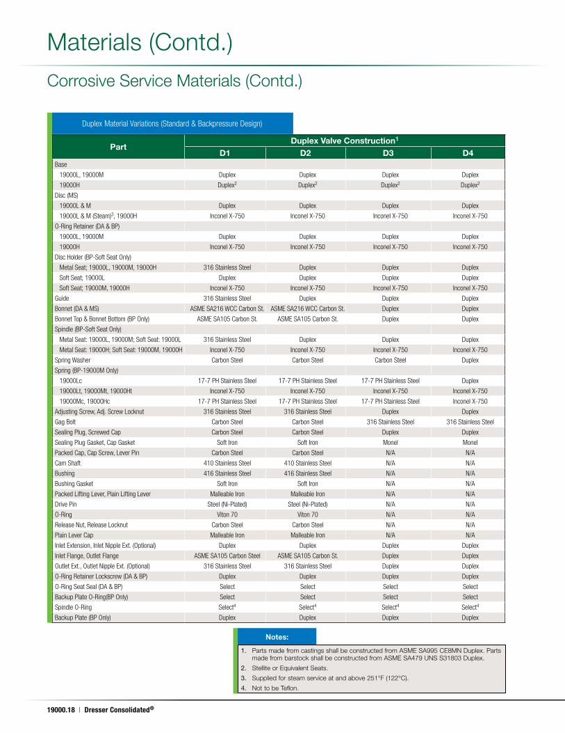
Duplex Material Variations (Standard & Backpressure Design)
Materials (Contd .)
PartDuplex Valve Construction1
D1 D2 D3 D4Base
19000L, 19000M Duplex Duplex Duplex Duplex
19000H Duplex2 Duplex2 Duplex2 Duplex2
Disc (MS)
19000L & M Duplex Duplex Duplex Duplex
19000L & M (Steam)3, 19000H Inconel X-750 Inconel X-750 Inconel X-750 Inconel X-750
O-Ring Retainer (DA & BP)
19000L, 19000M Duplex Duplex Duplex Duplex
19000H Inconel X-750 Inconel X-750 Inconel X-750 Inconel X-750
Disc Holder (BP-Soft Seat Only)
Metal Seat; 19000L, 19000M, 19000H 316 Stainless Steel Duplex Duplex Duplex
Soft Seat; 19000L Duplex Duplex Duplex Duplex
Soft Seat; 19000M, 19000H Inconel X-750 Inconel X-750 Inconel X-750 Inconel X-750
Guide 316 Stainless Steel Duplex Duplex Duplex
Bonnet (DA & MS) ASME SA216 WCC Carbon St. ASME SA216 WCC Carbon St. Duplex Duplex
Bonnet Top & Bonnet Bottom (BP Only) ASME SA105 Carbon St. ASME SA105 Carbon St. Duplex Duplex
Spindle (BP-Soft Seat Only)
Metal Seat: 19000L, 19000M; Soft Seat: 19000L 316 Stainless Steel Duplex Duplex Duplex
Metal Seat: 19000H; Soft Seat: 19000M, 19000H Inconel X-750 Inconel X-750 Inconel X-750 Inconel X-750
Spring Washer Carbon Steel Carbon Steel Carbon Steel Duplex
Spring (BP-19000M Only)
19000Lc 17-7 PH Stainless Steel 17-7 PH Stainless Steel 17-7 PH Stainless Steel Duplex
19000Lt, 19000Mt, 19000Ht Inconel X-750 Inconel X-750 Inconel X-750 Inconel X-750
19000Mc, 19000Hc 17-7 PH Stainless Steel 17-7 PH Stainless Steel 17-7 PH Stainless Steel Inconel X-750
Adjusting Screw, Adj. Screw Locknut 316 Stainless Steel 316 Stainless Steel Duplex Duplex
Gag Bolt Carbon Steel Carbon Steel 316 Stainless Steel 316 Stainless Steel
Sealing Plug, Screwed Cap Carbon Steel Carbon Steel Duplex Duplex
Sealing Plug Gasket, Cap Gasket Soft Iron Soft Iron Monel Monel
Packed Cap, Cap Screw, Lever Pin Carbon Steel Carbon Steel N/A N/A
Cam Shaft 410 Stainless Steel 410 Stainless Steel N/A N/A
Bushing 416 Stainless Steel 416 Stainless Steel N/A N/A
Bushing Gasket Soft Iron Soft Iron N/A N/A
Packed Lifting Lever, Plain Lifting Lever Malleable Iron Malleable Iron N/A N/A
Drive Pin Steel (Ni-Plated) Steel (Ni-Plated) N/A N/A
O-Ring Viton 70 Viton 70 N/A N/A
Release Nut, Release Locknut Carbon Steel Carbon Steel N/A N/A
Plain Lever Cap Malleable Iron Malleable Iron N/A N/A
Inlet Extension, Inlet Nipple Ext. (Optional) Duplex Duplex Duplex Duplex
Inlet Flange, Outlet Flange ASME SA105 Carbon Steel ASME SA105 Carbon St. Duplex Duplex
Outlet Ext., Outlet Nipple Ext. (Optional) 316 Stainless Steel 316 Stainless Steel Duplex Duplex
O-Ring Retainer Lockscrew (DA & BP) Duplex Duplex Duplex Duplex
O-Ring Seat Seal (DA & BP) Select Select Select Select
Backup Plate O-Ring(BP Only) Select Select Select Select
Spindle O-Ring Select4 Select4 Select4 Select4
Backup Plate (BP Only) Duplex Duplex Duplex Duplex
1. Parts made from castings shall be constructed from ASME SA995 CE8MN Duplex . Parts made from barstock shall be constructed from ASME SA479 UNS S31803 Duplex .
2. Stellite or Equivalent Seats .
3. Supplied for steam service at and above 251°F (122°C) .
4. Not to be Teflon .
Notes:
Corrosive Service Materials (Contd .)
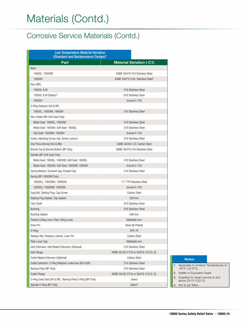
19000 Series Safety Relief Valve | 19000.19
May. 17, 2011
1. Applicable to Ambient Temperatures of -50°F (-45 .6°C) .
2. Stellite or Equivalent Seats
3. Supplied for steam service at and above 251°F (122°C) .
4. Not to be Teflon .
Notes:
Part Material Variation (-C1)Base
19000L, 19000M ASME SA479 316 Stainless Steel
19000H ASME SA479 316L Stainless Steel2
Disc (MS)
19000L & M 316 Stainless Steel
19000L & M (Steam)3 616 Stainless Steel
19000H Inconel X-750
O-Ring Retainer (DA & BP)
19000L, 19000M, 19000H 316 Stainless Steel
Disc Holder (BP-Soft Seat Only)
Metal Seat: 19000L, 19000M 316 Stainless Steel
Metal Seat: 19000H, Soft Seat: 19000L 316 Stainless Steel
Soft Seat: 19000M, 19000H Inconel X-750
Guide, Adjusting Screw, Adj. Screw Locknut 316 Stainless Steel
One Piece Bonnet (DA & MS) ASME SA352 LCC Carbon Steel
Bonnet Top & Bonnet Bottom (BP Only) ASME SA479 316 Stainless Steel
Spindle (BP-Soft Seat Only)
Metal Seat: 19000L, 19000M; Soft Seat: 19000L 316 Stainless Steel
Metal Seat: 19000H; Soft Seat: 19000M, 19000H Inconel X-750
Spring Washer, Screwed Cap, Packed Cap 316 Stainless Steel
Spring (BP-19000M Only)
19000Lc, 19000Mc, 19000Hc 17-7 PH Stainless Steel
19000Lt, 19000Mt, 19000Ht Inconel X-750
Gag Bolt, Sealing Plug, Cap Screw Carbon Steel
Sealing Plug Gasket, Cap Gasket Soft Iron
Cam Shaft 410 Stainless Steel
Bushing 416 Stainless Steel
Bushing Gasket Soft Iron
Packed Lifting Lever, Plain Lifting Lever Malleable Iron
Drive Pin Steel (Ni-Plated)
O-Ring EPR-70
Release Nut, Release Locknut, Lever Pin Carbon Steel
Plain Lever Cap Malleable Iron
Inlet Extension, Inlet Nipple Extension (Optional) 316 Stainless Steel
Inlet Flange ASME SA182-F316 or SA479-316 St. St.
Outlet Nipple Extension (Optional) Carbon Steel
Outlet Extension, O-Ring Retainer Lockscrew (DA & BP) 316 Stainless Steel
Backup Plate (BP Only) 316 Stainless Steel
Outlet Flange ASME SA182-F316 or SA479-316 St. St.
O-Ring Seat Seal (DA & BP), Backup Plate O-Ring (BP Only) Select
Spindle O-Ring (BP Only) Select4
Materials (Contd .)
Low Temperature Material Variation (Standard and Backpressure Design)1
Corrosive Service Materials (Contd .)
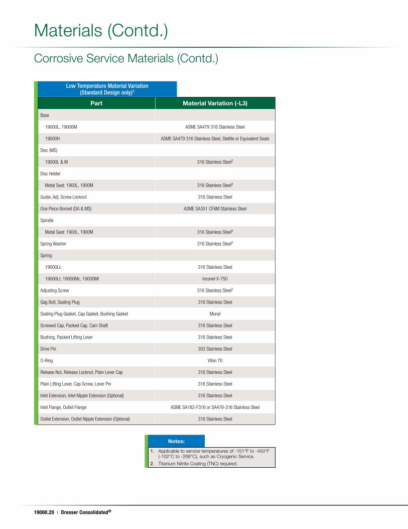
19000.20 | Dresser Consolidated®
May. 17, 2011
Corrosive Service Materials (Contd .)
Materials (Contd .)
Part Material Variation (-L3)
Base
19000L, 19000M ASME SA479 316 Stainless Steel
19000H ASME SA479 316 Stainless Steel, Stellite or Equivalent Seats
Disc (MS)
19000L & M 316 Stainless Steel2
Disc Holder
Metal Seat: 1900L, 1900M 316 Stainless Steel2
Guide, Adj. Screw Locknut 316 Stainless Steel
One Piece Bonnet (DA & MS) ASME SA351 CF8M Stainless Steel
Spindle
Metal Seat: 1900L, 1900M 316 Stainless Steel2
Spring Washer 316 Stainless Steel2
Spring
19000Lc 316 Stainless Steel
19000Lt, 19000Mc, 19000Mt Inconel X-750
Adjusting Screw 316 Stainless Steel2
Gag Bolt, Sealing Plug 316 Stainless Steel
Sealing Plug Gasket, Cap Gasket, Bushing Gasket Monel
Screwed Cap, Packed Cap, Cam Shaft 316 Stainless Steel
Bushing, Packed Lifting Lever 316 Stainless Steel
Drive Pin 303 Stainless Steel
O-Ring Viton 70
Release Nut, Release Locknut, Plain Lever Cap 316 Stainless Steel
Plain Lifting Lever, Cap Screw, Lever Pin 316 Stainless Steel
Inlet Extension, Inlet Nipple Extension (Optional) 316 Stainless Steel
Inlet Flange, Outlet Flange ASME SA182-F316 or SA479-316 Stainless Steel
Outlet Extension, Outlet Nipple Extension (Optional) 316 Stainless Steel
Low Temperature Material Variation (Standard Design only)1
1. Applicable to service temperatures of -151°F to -450°F (-102°C to -268°C), such as Cryogenic Service .
2. Titanium Nitrite Coating (TNC) required .
Notes:
19000 Series Safety Relief Valve | 19000.21
May. 17, 2011
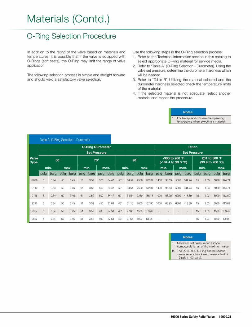
Materials (Contd .)
O-Ring Selection Procedure
In addition to the rating of the valve based on materials and temperatures, it is possible that if the valve is equipped with O-Rings (soft seats), the O-Ring may limit the range of valve application .
The following selection process is simple and straight forward and should yield a satisfactory valve selection .
Use the following steps in the O-Ring selection process:1 . Refer to the Technical Information section in this catalog to
select appropriate O-Ring material for service media .2 . Refer to “Table A” (O-Ring Selection - Durometer) . Using the
valve set pressure, determine the durometer hardness which will be needed .
3 . Refer to “Table B” . Utilizing the material selected and the durometer hardness selected check the temperature limits of the material .
4 . If the selected material is not adequate, select another material and repeat the procedure .
Valve Type
O-Ring Durometer Teflon
Set Pressure Set Pressure
501 701 902 -300 to 200 ºF (-184.4 to 93.3 ºC)
201 to 500 ºF (93.9 to 260 ºC)
min. max. min. max. min. max. min. max. min. max.
psig barg psig barg psig barg psig barg psig barg psig barg psig barg psig barg psig barg psig barg
19096 5 0.34 50 3.45 51 3.52 500 34.47 501 34.54 2500 172.37 1400 96.53 5000 344.74 15 1.03 5000 344.74
19110 5 0.34 50 3.45 51 3.52 500 34.47 501 34.54 2500 172.37 1400 96.53 5000 344.74 15 1.03 5000 344.74
19126 5 0.34 50 3.45 51 3.52 500 34.47 501 34.54 2250 155.13 1000 68.95 6000 413.69 15 1.03 6000 413.69
19226 5 0.34 50 3.45 51 3.52 450 31.03 451 31.10 2000 137.90 1000 68.95 6000 413.69 15 1.03 6000 413.69
19357 5 0.34 50 3.45 51 3.52 400 27.58 401 27.65 1500 103.42 - - - - 15 1.03 1500 103.42
19567 5 0.34 50 3.45 51 3.52 400 27.58 401 27.65 1000 68.95 - - - - 15 1.03 1000 68.95
Table A: O-Ring Selection - Durometer
1. For fire applications use the operating temperature when selecting a material .
1. Maximum set pressure for silicone compounds is half of the maximum value .
2. The E9 62-90D O-Ring can be used in steam service to a lower pressure limit of 15 psig (1 .03 barg) .
Notes:
Notes:
19000.22 | Dresser Consolidated®
May. 17, 2011
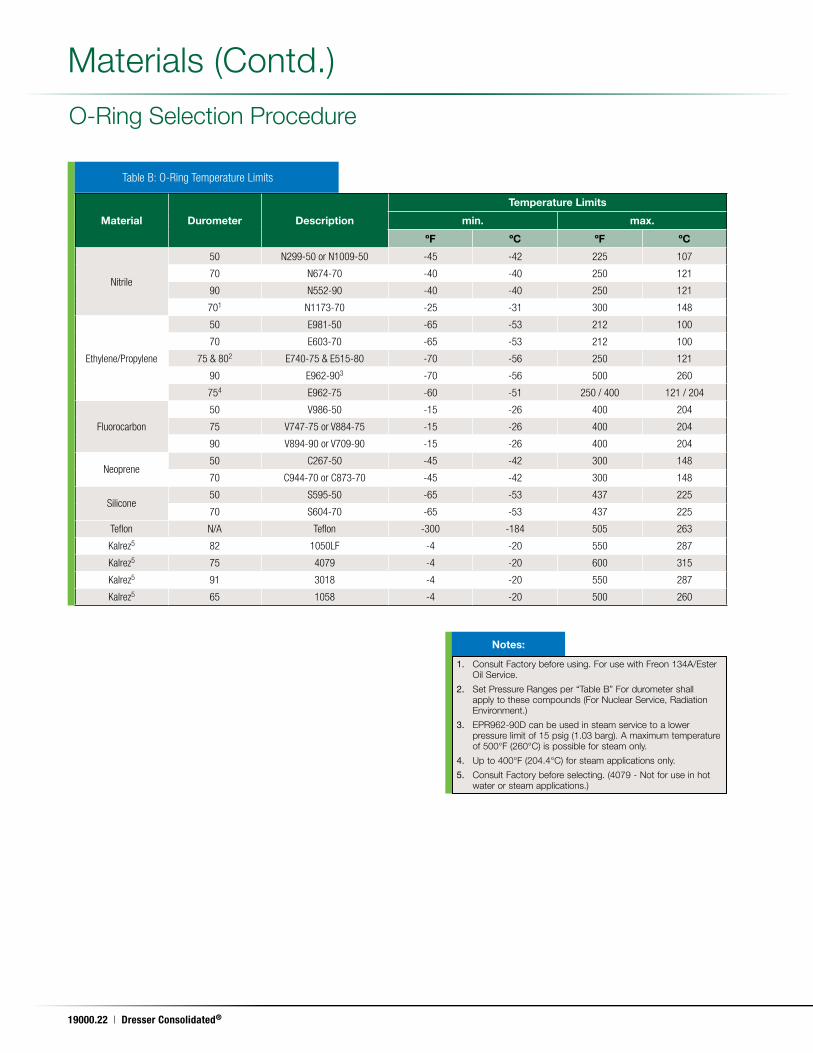
Materials (Contd .)
O-Ring Selection Procedure
Table B: O-Ring Temperature Limits
Material Durometer Description
Temperature Limits
min. max.
ºF ºC ºF ºC
Nitrile
50 N299-50 or N1009-50 -45 -42 225 107
70 N674-70 -40 -40 250 121
90 N552-90 -40 -40 250 121
701 N1173-70 -25 -31 300 148
Ethylene/Propylene
50 E981-50 -65 -53 212 100
70 E603-70 -65 -53 212 100
75 & 802 E740-75 & E515-80 -70 -56 250 121
90 E962-903 -70 -56 500 260
754 E962-75 -60 -51 250 / 400 121 / 204
Fluorocarbon
50 V986-50 -15 -26 400 204
75 V747-75 or V884-75 -15 -26 400 204
90 V894-90 or V709-90 -15 -26 400 204
Neoprene50 C267-50 -45 -42 300 148
70 C944-70 or C873-70 -45 -42 300 148
Silicone50 S595-50 -65 -53 437 225
70 S604-70 -65 -53 437 225
Teflon N/A Teflon -300 -184 505 263
Kalrez5 82 1050LF -4 -20 550 287
Kalrez5 75 4079 -4 -20 600 315
Kalrez5 91 3018 -4 -20 550 287
Kalrez5 65 1058 -4 -20 500 260
1. Consult Factory before using . For use with Freon 134A/Ester Oil Service .
2. Set Pressure Ranges per “Table B” For durometer shall apply to these compounds (For Nuclear Service, Radiation Environment .)
3. EPR962-90D can be used in steam service to a lower pressure limit of 15 psig (1 .03 barg) . A maximum temperature of 500°F (260°C) is possible for steam only .
4. Up to 400°F (204 .4°C) for steam applications only .
5. Consult Factory before selecting . (4079 - Not for use in hot water or steam applications .)
Notes:
19000 Series Safety Relief Valve | 19000.23
May. 17, 2011
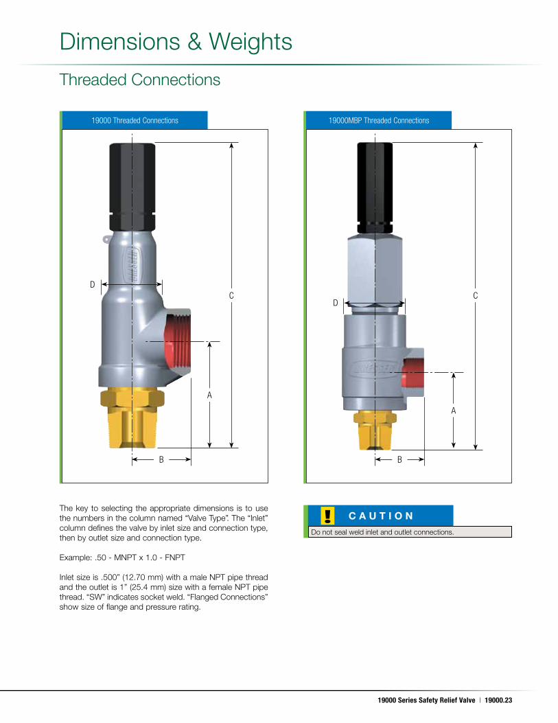
The key to selecting the appropriate dimensions is to use the numbers in the column named “Valve Type” . The “Inlet” column defines the valve by inlet size and connection type, then by outlet size and connection type .
Example: .50 - MNPT x 1 .0 - FNPT
Inlet size is .500” (12 .70 mm) with a male NPT pipe thread and the outlet is 1” (25 .4 mm) size with a female NPT pipe thread . “SW” indicates socket weld . “Flanged Connections” show size of flange and pressure rating .
C CD
D
A
A
B B
Threaded Connections
19000 Threaded Connections 19000MBP Threaded Connections
!Do not seal weld inlet and outlet connections .
C A U T I O N
Dimensions & Weights
19000.24 | Dresser Consolidated®
May. 17, 2011
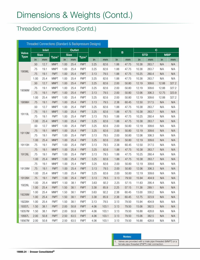
Valve Type
Inlet OutletA B
C
SizeType1
SizeType1
STD MBP
in mm in mm in mm in mm in mm in mm
19096L
.50 12.7 MNPT 1.00 25.4 FNPT 3.25 82.6 1.88 47.75 10.38 263.7 N/A N/A
.75 19.1 MNPT 1.00 25.4 FNPT 3.25 82.6 1.88 47.75 10.38 263.7 N/A N/A
.75 19.1 FNPT 1.00 25.4 FNPT 3.13 79.5 1.88 47.75 10.25 260.4 N/A N/A
1.00 25.4 MNPT 1.00 25.4 FNPT 3.25 82.6 1.88 47.75 10.38 263.7 N/A N/A
19096M
.50 12.7 MNPT 1.00 25.4 FNPT 3.25 82.6 2.00 50.80 12.19 309.6 12.88 327.2
.75 19.1 MNPT 1.00 25.4 FNPT 3.25 82.6 2.00 50.80 12.19 309.6 12.88 327.2
.75 19.1 FNPT 1.00 25.4 FNPT 3.13 79.5 2.00 50.80 12.06 306.3 12.75 323.9
1.00 25.4 MNPT 1.00 25.4 FNPT 3.25 82.6 2.00 50.80 12.19 309.6 12.88 327.2
19096H .75 19.1 FNPT 1.00 25.4 FNPT 3.13 79.5 2.38 60.45 12.50 317.5 N/A N/A
19110L
.50 12.7 MNPT 1.00 25.4 FNPT 3.25 82.6 1.88 47.75 10.38 263.7 N/A N/A
.75 19.1 MNPT 1.00 25.4 FNPT 3.25 82.6 1.88 47.75 10.38 263.7 N/A N/A
.75 19.1 FNPT 1.00 25.4 FNPT 3.13 79.5 1.88 47.75 10.25 260.4 N/A N/A
1.00 25.4 MNPT 1.00 25.4 FNPT 3.25 82.6 1.88 47.75 10.38 263.7 N/A N/A
19110M
.50 12.7 MNPT 1.00 25.4 FNPT 3.25 82.6 2.00 50.80 12.19 309.6 N/A N/A
.75 19.1 MNPT 1.00 25.4 FNPT 3.25 82.6 2.00 50.80 12.19 309.6 N/A N/A
.75 19.1 FNPT 1.00 25.4 FNPT 3.13 79.5 2.00 50.80 12.06 306.3 N/A N/A
1.00 25.4 MNPT 1.00 25.4 FNPT 3.25 82.6 2.00 50.80 12.19 309.6 N/A N/A
19110H .75 19.1 FNPT 1.00 25.4 FNPT 3.13 79.5 2.38 60.45 12.50 317.5 N/A N/A
19126L
.75 19.1 MNPT 1.00 25.4 FNPT 3.25 82.6 1.88 47.75 10.38 263.7 N/A N/A
.75 19.1 FNPT 1.00 25.4 FNPT 3.13 79.5 1.88 47.75 10.25 260.4 N/A N/A
1.00 25.4 MNPT 1.00 25.4 FNPT 3.25 82.6 1.88 47.75 10.38 263.7 N/A N/A
19126M
.75 19.1 MNPT 1.00 25.4 FNPT 3.25 82.6 2.00 50.80 12.19 309.6 N/A N/A
.75 19.1 FNPT 1.00 25.4 FNPT 3.13 79.5 2.00 50.80 12.06 306.3 N/A N/A
1.00 25.4 MNPT 1.00 25.4 FNPT 3.25 82.6 2.00 50.80 12.19 309.6 N/A N/A
19126H .75 19.1 FNPT 1.00 25.4 FNPT 3.13 79.5 3.13 79.50 15.94 404.9 N/A N/A
19226L1.00 25.4 MNPT 1.50 38.1 FNPT 3.63 92.2 2.25 57.15 11.63 295.4 N/A N/A
1.00 25.4 FNPT 1.50 38.1 FNPT 3.38 85.9 2.25 57.15 11.38 289.1 N/A N/A
19226M1.00 25.4 MNPT 1.50 38.1 FNPT 3.63 92.2 2.38 60.45 13.00 330.2 N/A N/A
1.00 25.4 FNPT 1.50 38.1 FNPT 3.38 85.9 2.38 60.45 12.75 323.9 N/A N/A
19226H 1.00 25.4 FNPT 1.50 38.1 FNPT 3.13 79.5 3.13 79.50 15.94 404.9 N/A N/A
19357L 1.50 38.1 FNPT 2.00 50.8 FNPT 4.06 103.1 3.13 79.50 15.06 382.5 N/A N/A
19357M 1.50 38.1 FNPT 2.00 50.8 FNPT 4.06 103.1 3.13 79.50 16.88 428.8 N/A N/A
19567L 2.00 50.8 FNPT 2.50 63.5 FNPT 4.06 103.1 3.13 79.50 15.06 382.5 N/A N/A
19567M 2.00 50.8 FNPT 2.50 63.5 FNPT 4.06 103.1 3.13 79.50 16.88 428.8 N/A N/A
Threaded Connections (Standard & Backpressure Designs)
Threaded Connections (Contd .)
1. Valves are provided with a male pipe threaded (MNPT) or a female pipe threaded (FNPT) inlet connection .
Notes:
Dimensions & Weights (Contd .)
19000 Series Safety Relief Valve | 19000.25
May. 17, 2011
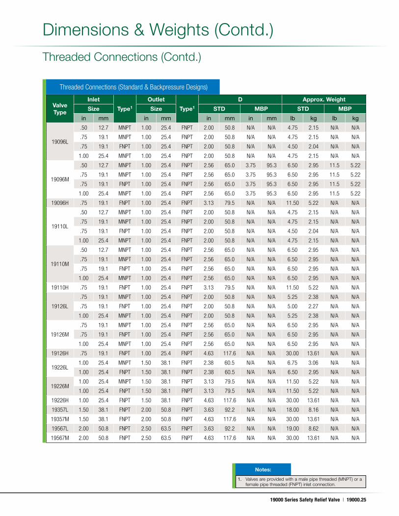
Valve Type
Inlet
Type1
Outlet
Type1
D Approx. Weight
Size Size STD MBP STD MBP
in mm in mm in mm in mm lb kg lb kg
19096L
.50 12.7 MNPT 1.00 25.4 FNPT 2.00 50.8 N/A N/A 4.75 2.15 N/A N/A
.75 19.1 MNPT 1.00 25.4 FNPT 2.00 50.8 N/A N/A 4.75 2.15 N/A N/A
.75 19.1 FNPT 1.00 25.4 FNPT 2.00 50.8 N/A N/A 4.50 2.04 N/A N/A
1.00 25.4 MNPT 1.00 25.4 FNPT 2.00 50.8 N/A N/A 4.75 2.15 N/A N/A
19096M
.50 12.7 MNPT 1.00 25.4 FNPT 2.56 65.0 3.75 95.3 6.50 2.95 11.5 5.22
.75 19.1 MNPT 1.00 25.4 FNPT 2.56 65.0 3.75 95.3 6.50 2.95 11.5 5.22
.75 19.1 FNPT 1.00 25.4 FNPT 2.56 65.0 3.75 95.3 6.50 2.95 11.5 5.22
1.00 25.4 MNPT 1.00 25.4 FNPT 2.56 65.0 3.75 95.3 6.50 2.95 11.5 5.22
19096H .75 19.1 FNPT 1.00 25.4 FNPT 3.13 79.5 N/A N/A 11.50 5.22 N/A N/A
19110L
.50 12.7 MNPT 1.00 25.4 FNPT 2.00 50.8 N/A N/A 4.75 2.15 N/A N/A
.75 19.1 MNPT 1.00 25.4 FNPT 2.00 50.8 N/A N/A 4.75 2.15 N/A N/A
.75 19.1 FNPT 1.00 25.4 FNPT 2.00 50.8 N/A N/A 4.50 2.04 N/A N/A
1.00 25.4 MNPT 1.00 25.4 FNPT 2.00 50.8 N/A N/A 4.75 2.15 N/A N/A
19110M
.50 12.7 MNPT 1.00 25.4 FNPT 2.56 65.0 N/A N/A 6.50 2.95 N/A N/A
.75 19.1 MNPT 1.00 25.4 FNPT 2.56 65.0 N/A N/A 6.50 2.95 N/A N/A
.75 19.1 FNPT 1.00 25.4 FNPT 2.56 65.0 N/A N/A 6.50 2.95 N/A N/A
1.00 25.4 MNPT 1.00 25.4 FNPT 2.56 65.0 N/A N/A 6.50 2.95 N/A N/A
19110H .75 19.1 FNPT 1.00 25.4 FNPT 3.13 79.5 N/A N/A 11.50 5.22 N/A N/A
19126L
.75 19.1 MNPT 1.00 25.4 FNPT 2.00 50.8 N/A N/A 5.25 2.38 N/A N/A
.75 19.1 FNPT 1.00 25.4 FNPT 2.00 50.8 N/A N/A 5.00 2.27 N/A N/A
1.00 25.4 MNPT 1.00 25.4 FNPT 2.00 50.8 N/A N/A 5.25 2.38 N/A N/A
19126M
.75 19.1 MNPT 1.00 25.4 FNPT 2.56 65.0 N/A N/A 6.50 2.95 N/A N/A
.75 19.1 FNPT 1.00 25.4 FNPT 2.56 65.0 N/A N/A 6.50 2.95 N/A N/A
1.00 25.4 MNPT 1.00 25.4 FNPT 2.56 65.0 N/A N/A 6.50 2.95 N/A N/A
19126H .75 19.1 FNPT 1.00 25.4 FNPT 4.63 117.6 N/A N/A 30.00 13.61 N/A N/A
19226L1.00 25.4 MNPT 1.50 38.1 FNPT 2.38 60.5 N/A N/A 6.75 3.06 N/A N/A
1.00 25.4 FNPT 1.50 38.1 FNPT 2.38 60.5 N/A N/A 6.50 2.95 N/A N/A
19226M1.00 25.4 MNPT 1.50 38.1 FNPT 3.13 79.5 N/A N/A 11.50 5.22 N/A N/A
1.00 25.4 FNPT 1.50 38.1 FNPT 3.13 79.5 N/A N/A 11.50 5.22 N/A N/A
19226H 1.00 25.4 FNPT 1.50 38.1 FNPT 4.63 117.6 N/A N/A 30.00 13.61 N/A N/A
19357L 1.50 38.1 FNPT 2.00 50.8 FNPT 3.63 92.2 N/A N/A 18.00 8.16 N/A N/A
19357M 1.50 38.1 FNPT 2.00 50.8 FNPT 4.63 117.6 N/A N/A 30.00 13.61 N/A N/A
19567L 2.00 50.8 FNPT 2.50 63.5 FNPT 3.63 92.2 N/A N/A 19.00 8.62 N/A N/A
19567M 2.00 50.8 FNPT 2.50 63.5 FNPT 4.63 117.6 N/A N/A 30.00 13.61 N/A N/A
Threaded Connections (Standard & Backpressure Designs)
Threaded Connections (Contd .)
1. Valves are provided with a male pipe threaded (MNPT) or a female pipe threaded (FNPT) inlet connection .
Notes:
Dimensions & Weights (Contd .)
19000.26 | Dresser Consolidated®
May. 17, 2011
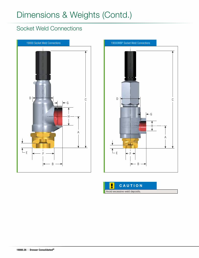
Socket Weld Connections
!Avoid excessive weld deposits .
C A U T I O N
C CD D
A
A
H
H
B B
F F
19000 Socket Weld Connections 19000MBP Socket Weld Connections
E E
G
G
Dimensions & Weights (Contd .)
19000 Series Safety Relief Valve | 19000.27
May. 17, 2011
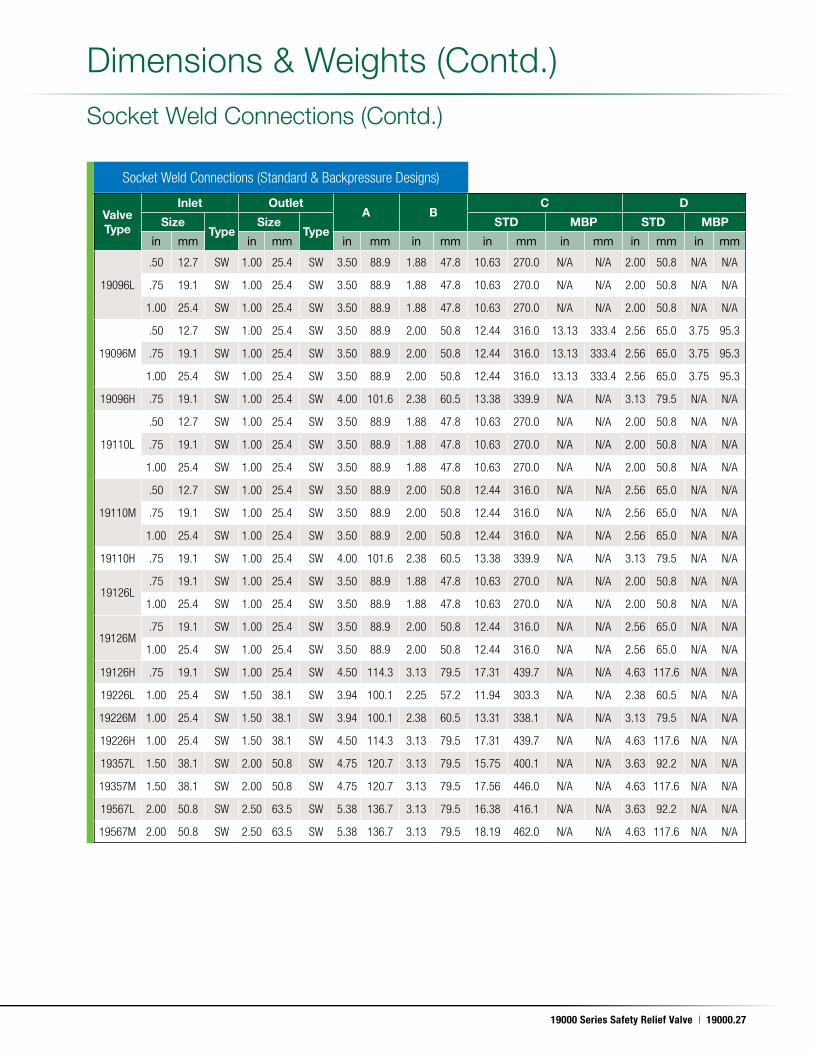
Socket Weld Connections (Contd .)
Socket Weld Connections (Standard & Backpressure Designs)
Dimensions & Weights (Contd .)
Valve Type
Inlet OutletA B
C D
SizeType
SizeType
STD MBP STD MBP
in mm in mm in mm in mm in mm in mm in mm in mm
19096L
.50 12.7 SW 1.00 25.4 SW 3.50 88.9 1.88 47.8 10.63 270.0 N/A N/A 2.00 50.8 N/A N/A
.75 19.1 SW 1.00 25.4 SW 3.50 88.9 1.88 47.8 10.63 270.0 N/A N/A 2.00 50.8 N/A N/A
1.00 25.4 SW 1.00 25.4 SW 3.50 88.9 1.88 47.8 10.63 270.0 N/A N/A 2.00 50.8 N/A N/A
19096M
.50 12.7 SW 1.00 25.4 SW 3.50 88.9 2.00 50.8 12.44 316.0 13.13 333.4 2.56 65.0 3.75 95.3
.75 19.1 SW 1.00 25.4 SW 3.50 88.9 2.00 50.8 12.44 316.0 13.13 333.4 2.56 65.0 3.75 95.3
1.00 25.4 SW 1.00 25.4 SW 3.50 88.9 2.00 50.8 12.44 316.0 13.13 333.4 2.56 65.0 3.75 95.3
19096H .75 19.1 SW 1.00 25.4 SW 4.00 101.6 2.38 60.5 13.38 339.9 N/A N/A 3.13 79.5 N/A N/A
19110L
.50 12.7 SW 1.00 25.4 SW 3.50 88.9 1.88 47.8 10.63 270.0 N/A N/A 2.00 50.8 N/A N/A
.75 19.1 SW 1.00 25.4 SW 3.50 88.9 1.88 47.8 10.63 270.0 N/A N/A 2.00 50.8 N/A N/A
1.00 25.4 SW 1.00 25.4 SW 3.50 88.9 1.88 47.8 10.63 270.0 N/A N/A 2.00 50.8 N/A N/A
19110M
.50 12.7 SW 1.00 25.4 SW 3.50 88.9 2.00 50.8 12.44 316.0 N/A N/A 2.56 65.0 N/A N/A
.75 19.1 SW 1.00 25.4 SW 3.50 88.9 2.00 50.8 12.44 316.0 N/A N/A 2.56 65.0 N/A N/A
1.00 25.4 SW 1.00 25.4 SW 3.50 88.9 2.00 50.8 12.44 316.0 N/A N/A 2.56 65.0 N/A N/A
19110H .75 19.1 SW 1.00 25.4 SW 4.00 101.6 2.38 60.5 13.38 339.9 N/A N/A 3.13 79.5 N/A N/A
19126L.75 19.1 SW 1.00 25.4 SW 3.50 88.9 1.88 47.8 10.63 270.0 N/A N/A 2.00 50.8 N/A N/A
1.00 25.4 SW 1.00 25.4 SW 3.50 88.9 1.88 47.8 10.63 270.0 N/A N/A 2.00 50.8 N/A N/A
19126M.75 19.1 SW 1.00 25.4 SW 3.50 88.9 2.00 50.8 12.44 316.0 N/A N/A 2.56 65.0 N/A N/A
1.00 25.4 SW 1.00 25.4 SW 3.50 88.9 2.00 50.8 12.44 316.0 N/A N/A 2.56 65.0 N/A N/A
19126H .75 19.1 SW 1.00 25.4 SW 4.50 114.3 3.13 79.5 17.31 439.7 N/A N/A 4.63 117.6 N/A N/A
19226L 1.00 25.4 SW 1.50 38.1 SW 3.94 100.1 2.25 57.2 11.94 303.3 N/A N/A 2.38 60.5 N/A N/A
19226M 1.00 25.4 SW 1.50 38.1 SW 3.94 100.1 2.38 60.5 13.31 338.1 N/A N/A 3.13 79.5 N/A N/A
19226H 1.00 25.4 SW 1.50 38.1 SW 4.50 114.3 3.13 79.5 17.31 439.7 N/A N/A 4.63 117.6 N/A N/A
19357L 1.50 38.1 SW 2.00 50.8 SW 4.75 120.7 3.13 79.5 15.75 400.1 N/A N/A 3.63 92.2 N/A N/A
19357M 1.50 38.1 SW 2.00 50.8 SW 4.75 120.7 3.13 79.5 17.56 446.0 N/A N/A 4.63 117.6 N/A N/A
19567L 2.00 50.8 SW 2.50 63.5 SW 5.38 136.7 3.13 79.5 16.38 416.1 N/A N/A 3.63 92.2 N/A N/A
19567M 2.00 50.8 SW 2.50 63.5 SW 5.38 136.7 3.13 79.5 18.19 462.0 N/A N/A 4.63 117.6 N/A N/A
19000.28 | Dresser Consolidated®
May. 17, 2011
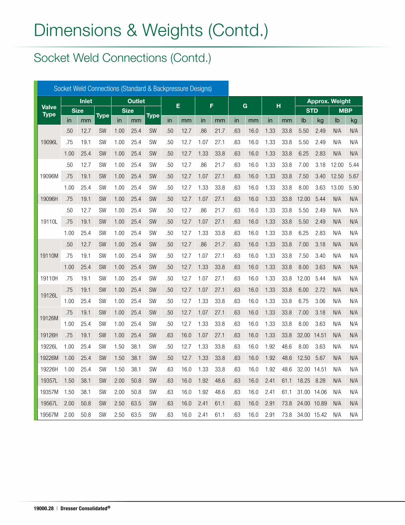
Socket Weld Connections (Contd .)
Dimensions & Weights (Contd .)
Valve Type
Inlet OutletE F G H
Approx. Weight
SizeType
SizeType
STD MBP
in mm in mm in mm in mm in mm in mm lb kg lb kg
19096L
.50 12.7 SW 1.00 25.4 SW .50 12.7 .86 21.7 .63 16.0 1.33 33.8 5.50 2.49 N/A N/A
.75 19.1 SW 1.00 25.4 SW .50 12.7 1.07 27.1 .63 16.0 1.33 33.8 5.50 2.49 N/A N/A
1.00 25.4 SW 1.00 25.4 SW .50 12.7 1.33 33.8 .63 16.0 1.33 33.8 6.25 2.83 N/A N/A
19096M
.50 12.7 SW 1.00 25.4 SW .50 12.7 .86 21.7 .63 16.0 1.33 33.8 7.00 3.18 12.00 5.44
.75 19.1 SW 1.00 25.4 SW .50 12.7 1.07 27.1 .63 16.0 1.33 33.8 7.50 3.40 12.50 5.67
1.00 25.4 SW 1.00 25.4 SW .50 12.7 1.33 33.8 .63 16.0 1.33 33.8 8.00 3.63 13.00 5.90
19096H .75 19.1 SW 1.00 25.4 SW .50 12.7 1.07 27.1 .63 16.0 1.33 33.8 12.00 5.44 N/A N/A
19110L
.50 12.7 SW 1.00 25.4 SW .50 12.7 .86 21.7 .63 16.0 1.33 33.8 5.50 2.49 N/A N/A
.75 19.1 SW 1.00 25.4 SW .50 12.7 1.07 27.1 .63 16.0 1.33 33.8 5.50 2.49 N/A N/A
1.00 25.4 SW 1.00 25.4 SW .50 12.7 1.33 33.8 .63 16.0 1.33 33.8 6.25 2.83 N/A N/A
19110M
.50 12.7 SW 1.00 25.4 SW .50 12.7 .86 21.7 .63 16.0 1.33 33.8 7.00 3.18 N/A N/A
.75 19.1 SW 1.00 25.4 SW .50 12.7 1.07 27.1 .63 16.0 1.33 33.8 7.50 3.40 N/A N/A
1.00 25.4 SW 1.00 25.4 SW .50 12.7 1.33 33.8 .63 16.0 1.33 33.8 8.00 3.63 N/A N/A
19110H .75 19.1 SW 1.00 25.4 SW .50 12.7 1.07 27.1 .63 16.0 1.33 33.8 12.00 5.44 N/A N/A
19126L.75 19.1 SW 1.00 25.4 SW .50 12.7 1.07 27.1 .63 16.0 1.33 33.8 6.00 2.72 N/A N/A
1.00 25.4 SW 1.00 25.4 SW .50 12.7 1.33 33.8 .63 16.0 1.33 33.8 6.75 3.06 N/A N/A
19126M.75 19.1 SW 1.00 25.4 SW .50 12.7 1.07 27.1 .63 16.0 1.33 33.8 7.00 3.18 N/A N/A
1.00 25.4 SW 1.00 25.4 SW .50 12.7 1.33 33.8 .63 16.0 1.33 33.8 8.00 3.63 N/A N/A
19126H .75 19.1 SW 1.00 25.4 SW .63 16.0 1.07 27.1 .63 16.0 1.33 33.8 32.00 14.51 N/A N/A
19226L 1.00 25.4 SW 1.50 38.1 SW .50 12.7 1.33 33.8 .63 16.0 1.92 48.6 8.00 3.63 N/A N/A
19226M 1.00 25.4 SW 1.50 38.1 SW .50 12.7 1.33 33.8 .63 16.0 1.92 48.6 12.50 5.67 N/A N/A
19226H 1.00 25.4 SW 1.50 38.1 SW .63 16.0 1.33 33.8 .63 16.0 1.92 48.6 32.00 14.51 N/A N/A
19357L 1.50 38.1 SW 2.00 50.8 SW .63 16.0 1.92 48.6 .63 16.0 2.41 61.1 18.25 8.28 N/A N/A
19357M 1.50 38.1 SW 2.00 50.8 SW .63 16.0 1.92 48.6 .63 16.0 2.41 61.1 31.00 14.06 N/A N/A
19567L 2.00 50.8 SW 2.50 63.5 SW .63 16.0 2.41 61.1 .63 16.0 2.91 73.8 24.00 10.89 N/A N/A
19567M 2.00 50.8 SW 2.50 63.5 SW .63 16.0 2.41 61.1 .63 16.0 2.91 73.8 34.00 15.42 N/A N/A
Socket Weld Connections (Standard & Backpressure Designs)
19000 Series Safety Relief Valve | 19000.29
May. 17, 2011
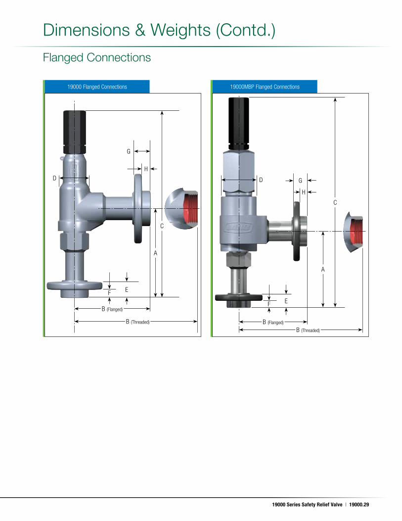
19000MBP Flanged Connections19000 Flanged Connections
Flanged Connections
C
C
D D
A
A
H
H
B (Flanged)
B (Flanged)B (Threaded)
B (Threaded)
F
F E
G
G
E
Dimensions & Weights (Contd .)
19000.30 | Dresser Consolidated®
May. 17, 2011
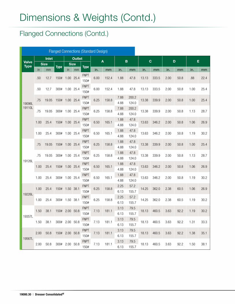
Flanged Connections (Standard Design)
Valve Type
Inlet OutletA B C D E
SizeType
SizeType
in mm in mm in. mm in. mm in. mm in. mm in. mm
19096L19110L
.50 12.7 150# 1.00 25.4FNPT
6.00 152.4 1.88 47.8 13.13 333.5 2.00 50.8 .88 22.4150#
.50 12.7 300# 1.00 25.4FNPT
6.00 152.4 1.88 47.8 13.13 333.5 2.00 50.8 1.00 25.4150#
.75 19.05 150# 1.00 25.4FNPT
6.25 158.87.88 200.2
13.38 339.9 2.00 50.8 1.00 25.4150# 4.88 124.0
.75 19.05 300# 1.00 25.4FNPT
6.25 158.87.88 200.2
13.38 339.9 2.00 50.8 1.13 28.7150# 4.88 124.0
1.00 25.4 150# 1.00 25.4FNPT
6.50 165.11.88 47.8
13.63 346.2 2.00 50.8 1.06 26.9150# 4.88 124.0
1.00 25.4 300# 1.00 25.4FNPT
6.50 165.11.88 47.8
13.63 346.2 2.00 50.8 1.19 30.2150# 4.88 124.0
19126L
.75 19.05 150# 1.00 25.4FNPT
6.25 158.81.88 47.8
13.38 339.9 2.00 50.8 1.00 25.4150# 4.88 124.0
.75 19.05 300# 1.00 25.4FNPT
6.25 158.81.88 47.8
13.38 339.9 2.00 50.8 1.13 28.7150# 4.88 124.0
1.00 25.4 150# 1.00 25.4FNPT
6.50 165.11.88 47.8
13.63 346.2 2.00 50.8 1.06 26.9150# 4.88 124.0
1.00 25.4 300# 1.00 25.4FNPT
6.50 165.11.88 47.8
13.63 346.2 2.00 50.8 1.19 30.2150# 4.88 124.0
19226L
1.00 25.4 150# 1.50 38.1FNPT
6.25 158.82.25 57.2
14.25 362.0 2.38 60.5 1.06 26.9150# 6.13 155.7
1.00 25.4 300# 1.50 38.1FNPT
6.25 158.82.25 57.2
14.25 362.0 2.38 60.5 1.19 30.2150# 6.13 155.7
19357L
1.50 38.1 150# 2.00 50.8FNPT
7.13 181.13.13 79.5
18.13 460.5 3.63 92.2 1.19 30.2150# 6.13 155.7
1.50 38.1 300# 2.00 50.8FNPT
7.13 181.13.13 79.5
18.13 460.5 3.63 92.2 1.31 33.3150# 6.13 155.7
19567L
2.00 50.8 150# 2.00 50.8FNPT
7.13 181.13.13 79.5
18.13 460.5 3.63 92.2 1.38 35.1150# 6.13 155.7
2.00 50.8 300# 2.00 50.8FNPT
7.13 181.13.13 79.5
18.13 460.5 3.63 92.2 1.50 38.1150# 6.13 155.7
Flanged Connections (Contd .)
Dimensions & Weights (Contd .)
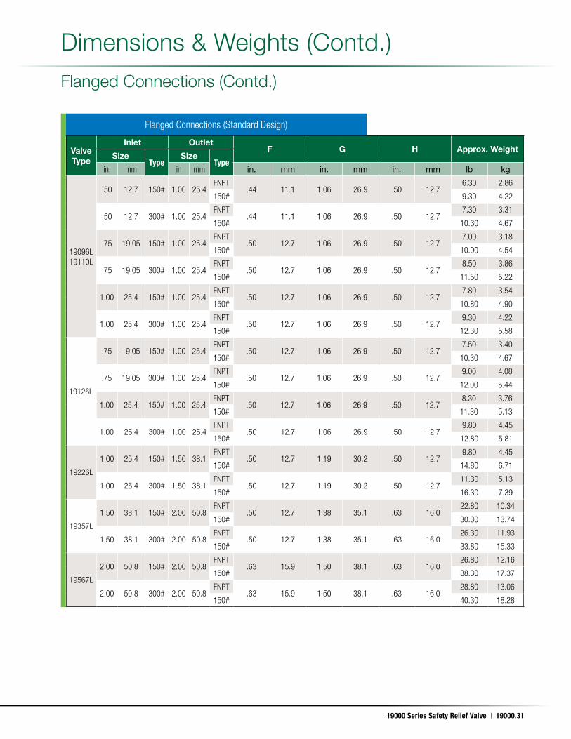
19000 Series Safety Relief Valve | 19000.31
May. 17, 2011
Valve Type
Inlet OutletF G H Approx. Weight
SizeType
SizeType
in. mm in mm in. mm in. mm in. mm lb kg
19096L19110L
.50 12.7 150# 1.00 25.4FNPT
.44 11.1 1.06 26.9 .50 12.76.30 2.86
150# 9.30 4.22
.50 12.7 300# 1.00 25.4FNPT
.44 11.1 1.06 26.9 .50 12.77.30 3.31
150# 10.30 4.67
.75 19.05 150# 1.00 25.4FNPT
.50 12.7 1.06 26.9 .50 12.77.00 3.18
150# 10.00 4.54
.75 19.05 300# 1.00 25.4FNPT
.50 12.7 1.06 26.9 .50 12.78.50 3.86
150# 11.50 5.22
1.00 25.4 150# 1.00 25.4FNPT
.50 12.7 1.06 26.9 .50 12.77.80 3.54
150# 10.80 4.90
1.00 25.4 300# 1.00 25.4FNPT
.50 12.7 1.06 26.9 .50 12.79.30 4.22
150# 12.30 5.58
19126L
.75 19.05 150# 1.00 25.4FNPT
.50 12.7 1.06 26.9 .50 12.77.50 3.40
150# 10.30 4.67
.75 19.05 300# 1.00 25.4FNPT
.50 12.7 1.06 26.9 .50 12.79.00 4.08
150# 12.00 5.44
1.00 25.4 150# 1.00 25.4FNPT
.50 12.7 1.06 26.9 .50 12.78.30 3.76
150# 11.30 5.13
1.00 25.4 300# 1.00 25.4FNPT
.50 12.7 1.06 26.9 .50 12.79.80 4.45
150# 12.80 5.81
19226L
1.00 25.4 150# 1.50 38.1FNPT
.50 12.7 1.19 30.2 .50 12.79.80 4.45
150# 14.80 6.71
1.00 25.4 300# 1.50 38.1FNPT
.50 12.7 1.19 30.2 .50 12.711.30 5.13
150# 16.30 7.39
19357L
1.50 38.1 150# 2.00 50.8FNPT
.50 12.7 1.38 35.1 .63 16.022.80 10.34
150# 30.30 13.74
1.50 38.1 300# 2.00 50.8FNPT
.50 12.7 1.38 35.1 .63 16.026.30 11.93
150# 33.80 15.33
19567L
2.00 50.8 150# 2.00 50.8FNPT
.63 15.9 1.50 38.1 .63 16.026.80 12.16
150# 38.30 17.37
2.00 50.8 300# 2.00 50.8FNPT
.63 15.9 1.50 38.1 .63 16.028.80 13.06
150# 40.30 18.28
Flanged Connections (Standard Design)
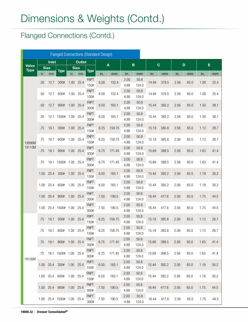
Flanged Connections (Contd .)
Dimensions & Weights (Contd .)
19000.32 | Dresser Consolidated®
May. 17, 2011
Valve Type
Inlet OutletA B C D E
SizeType
SizeType
in mm in mm in. mm in. mm in. mm in. mm in. mm
19096M19110M
.50 12.7 300# 1.00 25.4FNPT
6.00 152.42.00 50.8
14.94 379.5 2.56 65.0 1.00 25.4150# 4.88 124.0
.50 12.7 600# 1.00 25.4FNPT
6.00 152.42.00 50.8
14.94 379.5 2.56 65.0 1.00 25.4150# 4.88 124.0
.50 12.7 900# 1.00 25.4FNPT
6.50 165.12.00 50.8
15.44 392.2 2.56 65.0 1.50 38.1300# 4.88 124.0
.50 12.7 1500# 1.00 25.4FNPT
6.50 165.12.00 50.8
15.44 392.2 2.56 65.0 1.50 38.1300# 4.88 124.0
.75 19.1 300# 1.00 25.4FNPT
6.25 158.752.00 50.8
15.19 385.8 2.56 65.0 1.13 28.7150# 4.88 124.0
.75 19.1 600# 1.00 25.4FNPT
6.25 158.752.00 50.8
15.19 385.8 2.56 65.0 1.13 28.7150# 4.88 124.0
.75 19.1 900# 1.00 25.4FNPT
6.75 171.452.00 50.8
15.69 398.5 2.56 65.0 1.63 41.4300# 4.88 124.0
.75 19.1 1500# 1.00 25.4FNPT
6.75 171.452.00 50.8
15.69 398.5 2.56 65.0 1.63 41.4300# 4.88 124.0
1.00 25.4 300# 1.00 25.4FNPT
6.50 165.12.00 50.8
15.44 392.2 2.56 65.0 1.19 30.2150# 4.88 124.0
1.00 25.4 600# 1.00 25.4FNPT
6.50 165.12.00 50.8
15.44 392.2 2.56 65.0 1.19 30.2150# 4.88 124.0
1.00 25.4 900# 1.00 25.4FNPT
7.50 190.52.00 50.8
16.44 417.6 2.56 65.0 1.75 44.5300# 4.88 124.0
1.00 25.4 1500# 1.00 25.4FNPT
7.50 190.52.00 50.8
16.44 417.6 2.56 65.0 1.75 44.5300# 4.88 124.0
19126M
.75 19.1 300# 1.00 25.4FNPT
6.25 158.752.00 50.8
15.19 385.8 2.56 65.0 1.13 28.7150# 4.88 124.0
.75 19.1 600# 1.00 25.4FNPT
6.25 158.752.00 50.8
15.19 385.8 2.56 65.0 1.13 28.7150# 4.88 124.0
.75 19.1 900# 1.00 25.4FNPT
6.75 171.452.00 50.8
15.69 398.5 2.56 65.0 1.63 41.4300# 4.88 124.0
.75 19.1 1500# 1.00 25.4FNPT
6.75 171.452.00 50.8
15.69 398.5 2.56 65.0 1.63 41.4300# 4.88 124.0
1.00 25.4 300# 1.00 25.4FNPT
6.50 165.12.00 50.8
15.44 392.2 2.56 65.0 1.19 30.2150# 4.88 124.0
1.00 25.4 600# 1.00 25.4FNPT
6.50 165.12.00 50.8
15.44 392.2 2.56 65.0 1.19 30.2150# 4.88 124.0
1.00 25.4 900# 1.00 25.4FNPT
7.50 190.52.00 50.8
16.44 417.6 2.56 65.0 1.75 44.5300# 4.88 124.0
1.00 25.4 1500# 1.00 25.4FNPT
7.50 190.52.00 50.8
16.44 417.6 2.56 65.0 1.75 44.5300# 4.88 124.0
Flanged Connections (Standard Design)
Flanged Connections (Contd .)
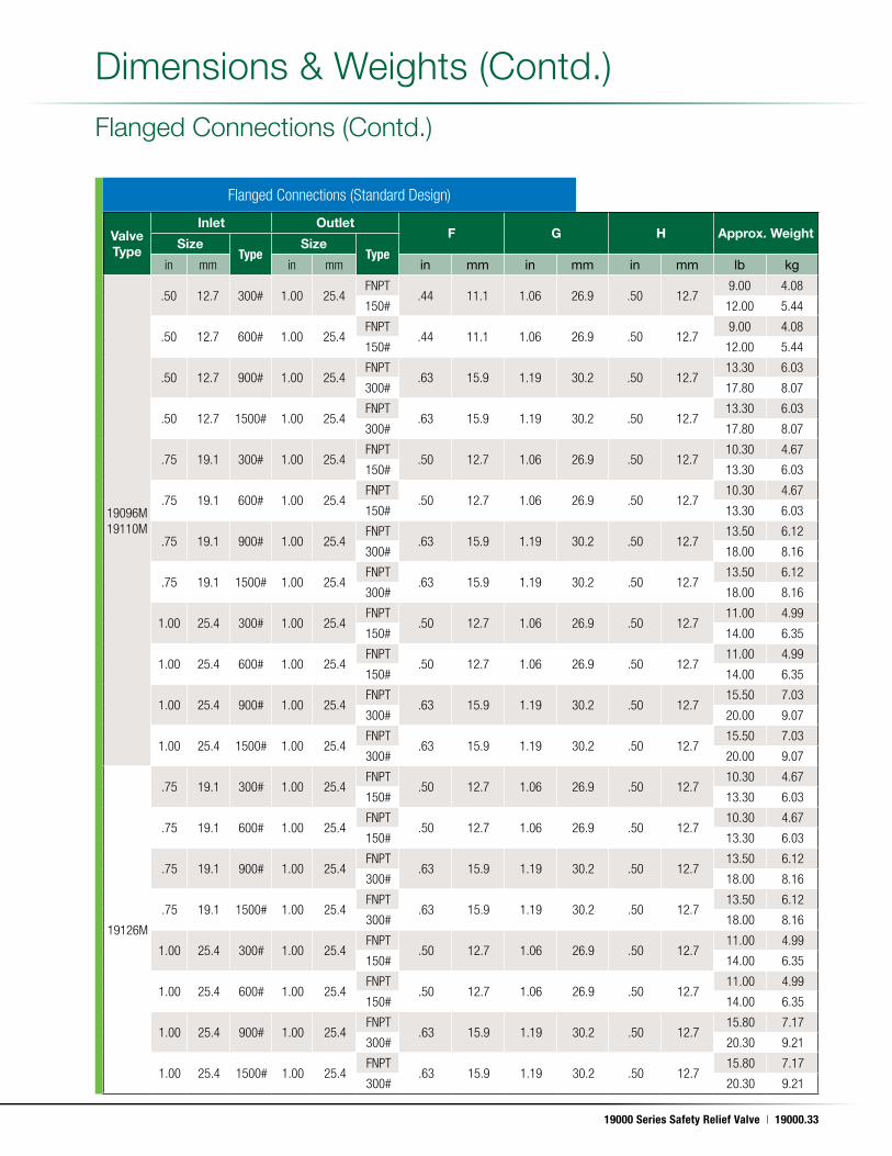
Dimensions & Weights (Contd .)
19000 Series Safety Relief Valve | 19000.33
May. 17, 2011
Valve Type
Inlet OutletF G H Approx. Weight
SizeType
SizeType
in mm in mm in mm in mm in mm lb kg
19096M19110M
.50 12.7 300# 1.00 25.4FNPT
.44 11.1 1.06 26.9 .50 12.79.00 4.08
150# 12.00 5.44
.50 12.7 600# 1.00 25.4FNPT
.44 11.1 1.06 26.9 .50 12.79.00 4.08
150# 12.00 5.44
.50 12.7 900# 1.00 25.4FNPT
.63 15.9 1.19 30.2 .50 12.713.30 6.03
300# 17.80 8.07
.50 12.7 1500# 1.00 25.4FNPT
.63 15.9 1.19 30.2 .50 12.713.30 6.03
300# 17.80 8.07
.75 19.1 300# 1.00 25.4FNPT
.50 12.7 1.06 26.9 .50 12.710.30 4.67
150# 13.30 6.03
.75 19.1 600# 1.00 25.4FNPT
.50 12.7 1.06 26.9 .50 12.710.30 4.67
150# 13.30 6.03
.75 19.1 900# 1.00 25.4FNPT
.63 15.9 1.19 30.2 .50 12.713.50 6.12
300# 18.00 8.16
.75 19.1 1500# 1.00 25.4FNPT
.63 15.9 1.19 30.2 .50 12.713.50 6.12
300# 18.00 8.16
1.00 25.4 300# 1.00 25.4FNPT
.50 12.7 1.06 26.9 .50 12.711.00 4.99
150# 14.00 6.35
1.00 25.4 600# 1.00 25.4FNPT
.50 12.7 1.06 26.9 .50 12.711.00 4.99
150# 14.00 6.35
1.00 25.4 900# 1.00 25.4FNPT
.63 15.9 1.19 30.2 .50 12.715.50 7.03
300# 20.00 9.07
1.00 25.4 1500# 1.00 25.4FNPT
.63 15.9 1.19 30.2 .50 12.715.50 7.03
300# 20.00 9.07
19126M
.75 19.1 300# 1.00 25.4FNPT
.50 12.7 1.06 26.9 .50 12.710.30 4.67
150# 13.30 6.03
.75 19.1 600# 1.00 25.4FNPT
.50 12.7 1.06 26.9 .50 12.710.30 4.67
150# 13.30 6.03
.75 19.1 900# 1.00 25.4FNPT
.63 15.9 1.19 30.2 .50 12.713.50 6.12
300# 18.00 8.16
.75 19.1 1500# 1.00 25.4FNPT
.63 15.9 1.19 30.2 .50 12.713.50 6.12
300# 18.00 8.16
1.00 25.4 300# 1.00 25.4FNPT
.50 12.7 1.06 26.9 .50 12.711.00 4.99
150# 14.00 6.35
1.00 25.4 600# 1.00 25.4FNPT
.50 12.7 1.06 26.9 .50 12.711.00 4.99
150# 14.00 6.35
1.00 25.4 900# 1.00 25.4FNPT
.63 15.9 1.19 30.2 .50 12.715.80 7.17
300# 20.30 9.21
1.00 25.4 1500# 1.00 25.4FNPT
.63 15.9 1.19 30.2 .50 12.715.80 7.17
300# 20.30 9.21
Flanged Connections (Standard Design)
Flanged Connections (Contd .)
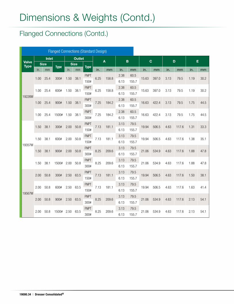
Dimensions & Weights (Contd .)
19000.34 | Dresser Consolidated®
May. 17, 2011
Valve Type
Inlet OutletA B C D E
SizeType
SizeType
in. mm in. mm in. mm in. mm in. mm in. mm in. mm
19226M
1.00 25.4 300# 1.50 38.1FNPT
6.25 158.82.38 60.5
15.63 397.0 3.13 79.5 1.19 30.2150# 6.13 155.7
1.00 25.4 600# 1.50 38.1FNPT
6.25 158.82.38 60.5
15.63 397.0 3.13 79.5 1.19 30.2150# 6.13 155.7
1.00 25.4 900# 1.50 38.1FNPT
7.25 184.22.38 60.5
16.63 422.4 3.13 79.5 1.75 44.5300# 6.13 155.7
1.00 25.4 1500# 1.50 38.1FNPT
7.25 184.22.38 60.5
16.63 422.4 3.13 79.5 1.75 44.5300# 6.13 155.7
19357M
1.50 38.1 300# 2.00 50.8FNPT
7.13 181.13.13 79.5
19.94 506.5 4.63 117.6 1.31 33.3150# 6.13 155.7
1.50 38.1 600# 2.00 50.8FNPT
7.13 181.13.13 79.5
19.94 506.5 4.63 117.6 1.38 35.1150# 6.13 155.7
1.50 38.1 900# 2.00 50.8FNPT
8.25 209.63.13 79.5
21.06 534.9 4.63 117.6 1.88 47.8300# 6.13 155.7
1.50 38.1 1500# 2.00 50.8FNPT
8.25 209.63.13 79.5
21.06 534.9 4.63 117.6 1.88 47.8300# 6.13 155.7
19567M
2.00 50.8 300# 2.50 63.5FNPT
7.13 181.13.13 79.5
19.94 506.5 4.63 117.6 1.50 38.1150# 6.13 155.7
2.00 50.8 600# 2.50 63.5FNPT
7.13 181.13.13 79.5
19.94 506.5 4.63 117.6 1.63 41.4150# 6.13 155.7
2.00 50.8 900# 2.50 63.5FNPT
8.25 209.63.13 79.5
21.06 534.9 4.63 117.6 2.13 54.1300# 6.13 155.7
2.00 50.8 1500# 2.50 63.5FNPT
8.25 209.63.13 79.5
21.06 534.9 4.63 117.6 2.13 54.1300# 6.13 155.7
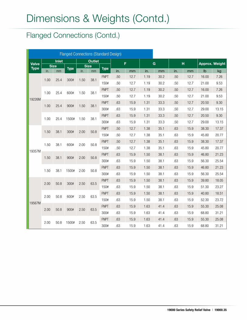
Flanged Connections (Standard Design)
Flanged Connections (Contd .)
Dimensions & Weights (Contd .)
19000 Series Safety Relief Valve | 19000.35
May. 17, 2011
Valve Type
Inlet OutletF G H Approx. Weight
SizeType
SizeType
in. mm in. mm in. mm in. mm in. mm lb kg
19226M
1.00 25.4 300# 1.50 38.1FNPT .50 12.7 1.19 30.2 .50 12.7 16.00 7.26
150# .50 12.7 1.19 30.2 .50 12.7 21.00 9.53
1.00 25.4 600# 1.50 38.1FNPT .50 12.7 1.19 30.2 .50 12.7 16.00 7.26
150# .50 12.7 1.19 30.2 .50 12.7 21.00 9.53
1.00 25.4 900# 1.50 38.1FNPT .63 15.9 1.31 33.3 .50 12.7 20.50 9.30
300# .63 15.9 1.31 33.3 .50 12.7 29.00 13.15
1.00 25.4 1500# 1.50 38.1FNPT .63 15.9 1.31 33.3 .50 12.7 20.50 9.30
300# .63 15.9 1.31 33.3 .50 12.7 29.00 13.15
19357M
1.50 38.1 300# 2.00 50.8FNPT .50 12.7 1.38 35.1 .63 15.9 38.30 17.37
150# .50 12.7 1.38 35.1 .63 15.9 45.80 20.77
1.50 38.1 600# 2.00 50.8FNPT .50 12.7 1.38 35.1 .63 15.9 38.30 17.37
150# .50 12.7 1.38 35.1 .63 15.9 45.80 20.77
1.50 38.1 900# 2.00 50.8FNPT .63 15.9 1.50 38.1 .63 15.9 46.80 21.23
300# .63 15.9 1.50 38.1 .63 15.9 56.30 25.54
1.50 38.1 1500# 2.00 50.8FNPT .63 15.9 1.50 38.1 .63 15.9 46.80 21.23
300# .63 15.9 1.50 38.1 .63 15.9 56.30 25.54
19567M
2.00 50.8 300# 2.50 63.5FNPT .63 15.9 1.50 38.1 .63 15.9 39.80 18.05
150# .63 15.9 1.50 38.1 .63 15.9 51.30 23.27
2.00 50.8 600# 2.50 63.5FNPT .63 15.9 1.50 38.1 .63 15.9 40.80 18.51
150# .63 15.9 1.50 38.1 .63 15.9 52.30 23.72
2.00 50.8 900# 2.50 63.5FNPT .63 15.9 1.63 41.4 .63 15.9 55.30 25.08
300# .63 15.9 1.63 41.4 .63 15.9 68.80 31.21
2.00 50.8 1500# 2.50 63.5FNPT .63 15.9 1.63 41.4 .63 15.9 55.30 25.08
300# .63 15.9 1.63 41.4 .63 15.9 68.80 31.21
Dimensions & Weights (Contd .)
Flanged Connections (Standard Design)
Flanged Connections (Contd .)
19000.36 | Dresser Consolidated®
May. 17, 2011
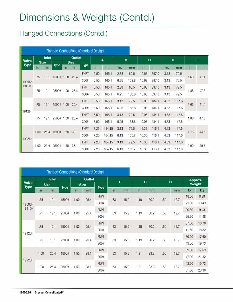
Flanged Connections (Standard Design)
Flanged Connections (Standard Design)
Valve Type
Inlet OutletA B C D E
SizeType
SizeType
in. mm in. mm in. mm in. mm in. mm in. mm in. mm
19096H19110H
.75 19.1 1500# 1.00 25.4FNPT 6.50 165.1 2.38 60.5 15.63 397.0 3.13 79.5
1.63 41.4300# 6.50 165.1 6.25 158.8 15.63 397.0 3.13 79.5
.75 19.1 2500# 1.00 25.4FNPT 6.50 165.1 2.38 60.5 15.63 397.0 3.13 79.5
1.88 47.8300# 6.50 165.1 6.25 158.8 15.63 397.0 3.13 79.5
19126H
.75 19.1 1500# 1.00 25.4FNPT 6.50 165.1 3.13 79.5 19.06 484.1 4.63 117.6
1.63 41.4300# 6.50 165.1 6.25 158.8 19.06 484.1 4.63 117.6
.75 19.1 2500# 1.00 25.4FNPT 6.50 165.1 3.13 79.5 19.06 484.1 4.63 117.6
1.88 47.8300# 6.50 165.1 6.25 158.8 19.06 484.1 4.63 117.6
19226H
1.00 25.4 1500# 1.50 38.1FNPT 7.25 184.15 3.13 79.5 16.38 416.1 4.63 117.6
1.75 44.5300# 7.25 184.15 6.13 155.7 16.38 416.1 4.63 117.6
1.00 25.4 2500# 1.50 38.1FNPT 7.25 184.15 3.13 79.5 16.38 416.1 4.63 117.6
2.00 50.8300# 7.25 184.15 6.13 155.7 16.38 416.1 4.63 117.6
Valve Type
Inlet OutletF G H
Approx. WeightSize
TypeSize
Typein. mm in. mm in mm in mm in mm lb kg
19096H19110H
.75 19.1 1500# 1.00 25.4FNPT
.63 15.9 1.19 30.2 .50 12.718.50 8.39
300# 23.00 10.43
.75 19.1 2500# 1.00 25.4FNPT
.63 15.9 1.19 30.2 .50 12.720.80 9.43
300# 25.30 11.48
19126H
.75 19.1 1500# 1.00 25.4FNPT
.63 15.9 1.19 30.2 .50 12.737.00 16.78
300# 41.50 18.82
.75 19.1 2500# 1.00 25.4FNPT
.63 15.9 1.19 30.2 .50 12.739.00 17.69
300# 43.50 19.73
19226H
1.00 25.4 1500# 1.50 38.1FNPT
.63 15.9 1.31 33.3 .50 12.739.00 17.69
300# 47.00 21.32
1.00 25.4 2500# 1.50 38.1FNPT
.63 15.9 1.31 33.3 .50 12.743.50 19.73
300# 51.50 23.36
Dimensions & Weights (Contd .)
Flanged Connections (Contd .)
19000 Series Safety Relief Valve | 19000.37
May. 17, 2011
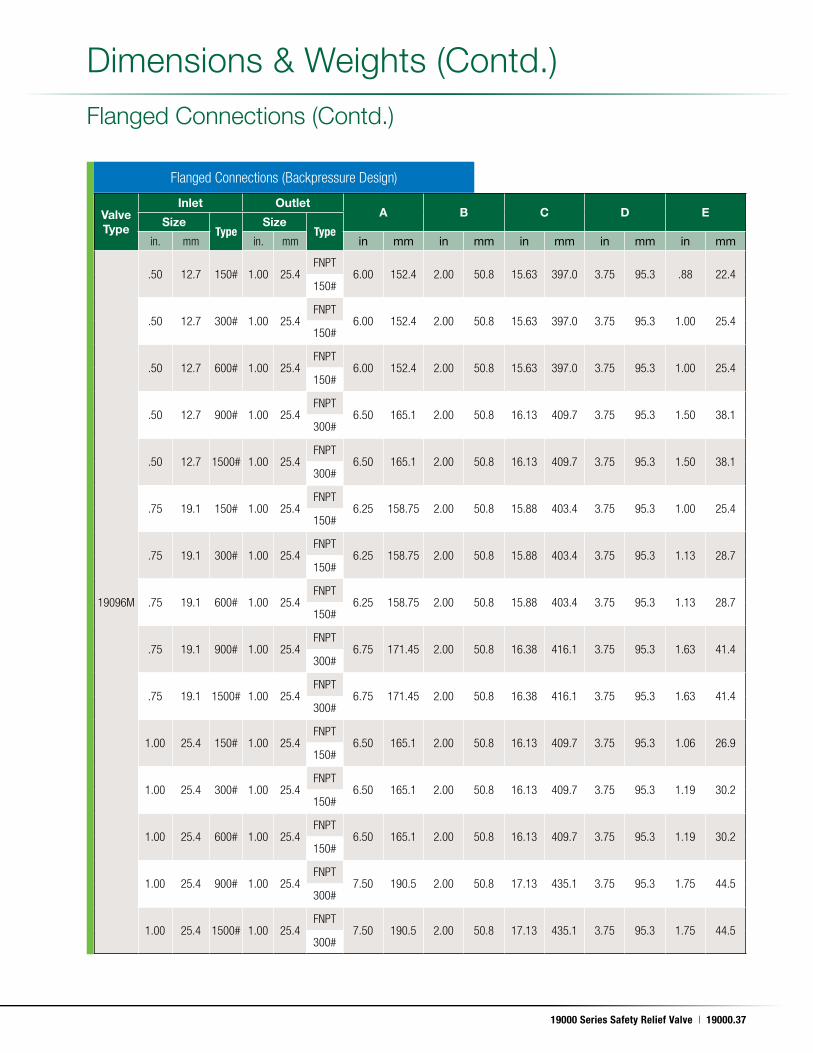
Valve Type
Inlet OutletA B C D E
SizeType
SizeType
in. mm in. mm in mm in mm in mm in mm in mm
19096M
.50 12.7 150# 1.00 25.4FNPT
6.00 152.4 2.00 50.8 15.63 397.0 3.75 95.3 .88 22.4150#
.50 12.7 300# 1.00 25.4FNPT
6.00 152.4 2.00 50.8 15.63 397.0 3.75 95.3 1.00 25.4150#
.50 12.7 600# 1.00 25.4FNPT
6.00 152.4 2.00 50.8 15.63 397.0 3.75 95.3 1.00 25.4150#
.50 12.7 900# 1.00 25.4FNPT
6.50 165.1 2.00 50.8 16.13 409.7 3.75 95.3 1.50 38.1300#
.50 12.7 1500# 1.00 25.4FNPT
6.50 165.1 2.00 50.8 16.13 409.7 3.75 95.3 1.50 38.1300#
.75 19.1 150# 1.00 25.4FNPT
6.25 158.75 2.00 50.8 15.88 403.4 3.75 95.3 1.00 25.4150#
.75 19.1 300# 1.00 25.4FNPT
6.25 158.75 2.00 50.8 15.88 403.4 3.75 95.3 1.13 28.7150#
.75 19.1 600# 1.00 25.4FNPT
6.25 158.75 2.00 50.8 15.88 403.4 3.75 95.3 1.13 28.7150#
.75 19.1 900# 1.00 25.4FNPT
6.75 171.45 2.00 50.8 16.38 416.1 3.75 95.3 1.63 41.4300#
.75 19.1 1500# 1.00 25.4FNPT
6.75 171.45 2.00 50.8 16.38 416.1 3.75 95.3 1.63 41.4300#
1.00 25.4 150# 1.00 25.4FNPT
6.50 165.1 2.00 50.8 16.13 409.7 3.75 95.3 1.06 26.9150#
1.00 25.4 300# 1.00 25.4FNPT
6.50 165.1 2.00 50.8 16.13 409.7 3.75 95.3 1.19 30.2150#
1.00 25.4 600# 1.00 25.4FNPT
6.50 165.1 2.00 50.8 16.13 409.7 3.75 95.3 1.19 30.2150#
1.00 25.4 900# 1.00 25.4FNPT
7.50 190.5 2.00 50.8 17.13 435.1 3.75 95.3 1.75 44.5300#
1.00 25.4 1500# 1.00 25.4FNPT
7.50 190.5 2.00 50.8 17.13 435.1 3.75 95.3 1.75 44.5300#
Flanged Connections (Backpressure Design)
Dimensions & Weights (Contd .)
Flanged Connections (Contd .)
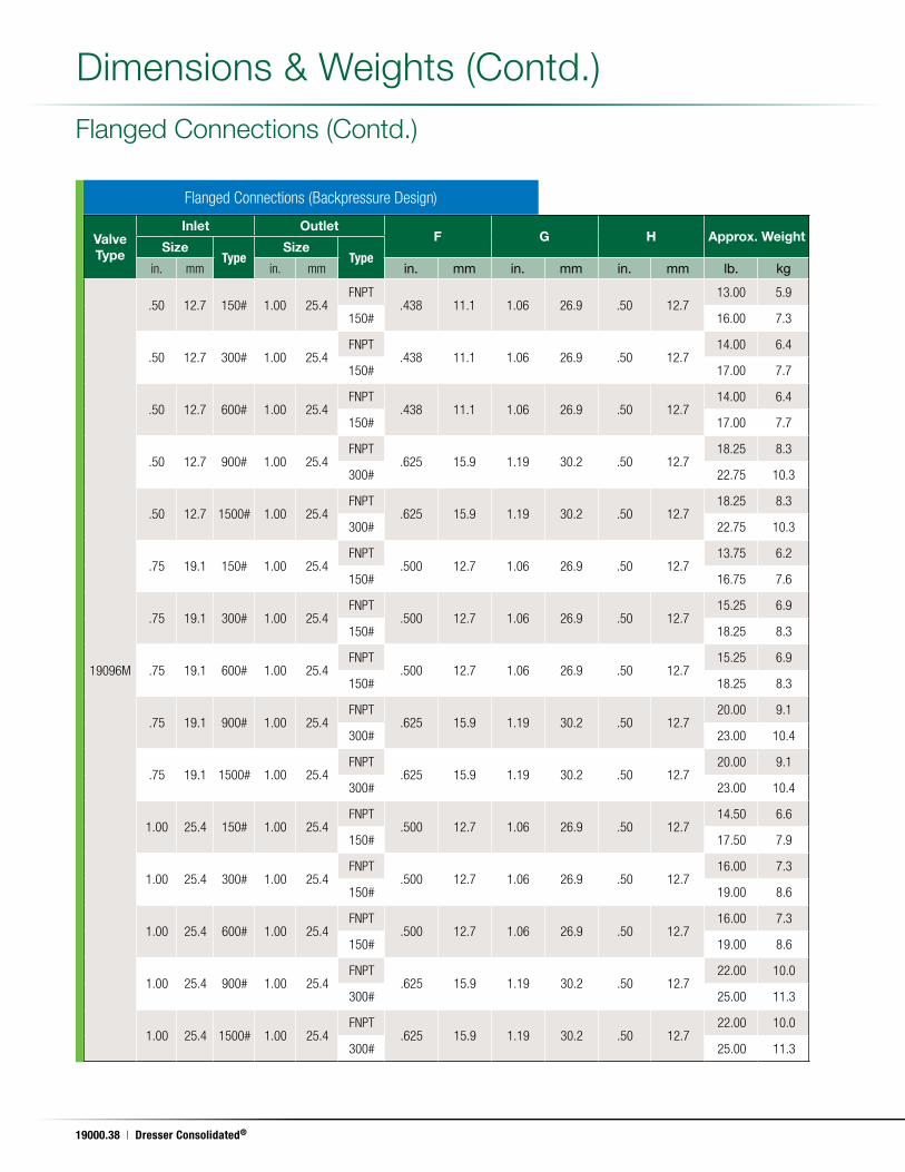
19000.38 | Dresser Consolidated®
May. 17, 2011
Flanged Connections (Backpressure Design)
Valve Type
Inlet OutletF G H Approx. Weight
SizeType
SizeType
in. mm in. mm in. mm in. mm in. mm lb. kg
19096M
.50 12.7 150# 1.00 25.4FNPT
.438 11.1 1.06 26.9 .50 12.713.00 5.9
150# 16.00 7.3
.50 12.7 300# 1.00 25.4FNPT
.438 11.1 1.06 26.9 .50 12.714.00 6.4
150# 17.00 7.7
.50 12.7 600# 1.00 25.4FNPT
.438 11.1 1.06 26.9 .50 12.714.00 6.4
150# 17.00 7.7
.50 12.7 900# 1.00 25.4FNPT
.625 15.9 1.19 30.2 .50 12.718.25 8.3
300# 22.75 10.3
.50 12.7 1500# 1.00 25.4FNPT
.625 15.9 1.19 30.2 .50 12.718.25 8.3
300# 22.75 10.3
.75 19.1 150# 1.00 25.4FNPT
.500 12.7 1.06 26.9 .50 12.713.75 6.2
150# 16.75 7.6
.75 19.1 300# 1.00 25.4FNPT
.500 12.7 1.06 26.9 .50 12.715.25 6.9
150# 18.25 8.3
.75 19.1 600# 1.00 25.4FNPT
.500 12.7 1.06 26.9 .50 12.715.25 6.9
150# 18.25 8.3
.75 19.1 900# 1.00 25.4FNPT
.625 15.9 1.19 30.2 .50 12.720.00 9.1
300# 23.00 10.4
.75 19.1 1500# 1.00 25.4FNPT
.625 15.9 1.19 30.2 .50 12.720.00 9.1
300# 23.00 10.4
1.00 25.4 150# 1.00 25.4FNPT
.500 12.7 1.06 26.9 .50 12.714.50 6.6
150# 17.50 7.9
1.00 25.4 300# 1.00 25.4FNPT
.500 12.7 1.06 26.9 .50 12.716.00 7.3
150# 19.00 8.6
1.00 25.4 600# 1.00 25.4FNPT
.500 12.7 1.06 26.9 .50 12.716.00 7.3
150# 19.00 8.6
1.00 25.4 900# 1.00 25.4FNPT
.625 15.9 1.19 30.2 .50 12.722.00 10.0
300# 25.00 11.3
1.00 25.4 1500# 1.00 25.4FNPT
.625 15.9 1.19 30.2 .50 12.722.00 10.0
300# 25.00 11.3
Dimensions & Weights (Contd .)
Flanged Connections (Contd .)
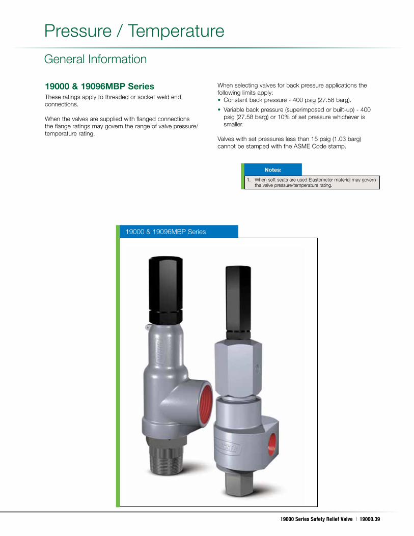
19000 Series Safety Relief Valve | 19000.39
May. 17, 2011
19000 & 19096MBP Series
19000 & 19096MBP SeriesThese ratings apply to threaded or socket weld end connections .
When the valves are supplied with flanged connections the flange ratings may govern the range of valve pressure/temperature rating .
When selecting valves for back pressure applications the following limits apply:• Constant back pressure - 400 psig (27 .58 barg) .
• Variable back pressure (superimposed or built-up) - 400 psig (27 .58 barg) or 10% of set pressure whichever is smaller .
Valves with set pressures less than 15 psig (1 .03 barg) cannot be stamped with the ASME Code stamp .
Pressure / Temperature
General Information
1. When soft seats are used Elastometer material may govern the valve pressure/temperature rating .
Notes:
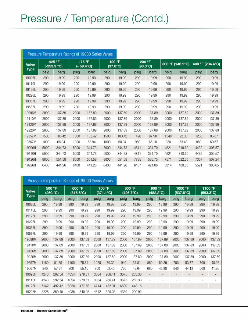
19000.40 | Dresser Consolidated®
May. 17, 2011
Pressure / Temperature (Contd .)
Pressure Temperature Ratings of 19000 Series Valves
Pressure Temperature Ratings of 19000 Series Valves
Valve Type
-425 °F (-253.9 °C)
-75 °F (- 59.4°C)
100 °F (37.8°C)
200 °F (93.3°C)
300 °F (148.9°C) 400 °F (204.4°C)
psig barg psig barg psig barg psig barg psig barg psig barg
19096L 290 19.99 290 19.99 290 19.99 290 19.99 290 19.99 290 19.99
19110L 290 19.99 290 19.99 290 19.99 290 19.99 290 19.99 290 19.99
19126L 290 19.99 290 19.99 290 19.99 290 19.99 290 19.99 290 19.99
19226L 290 19.99 290 19.99 290 19.99 290 19.99 290 19.99 290 19.99
19357L 290 19.99 290 19.99 290 19.99 290 19.99 290 19.99 290 19.99
19567L 290 19.99 290 19.99 290 19.99 290 19.99 290 19.99 290 19.99
19096M 2000 137.89 2000 137.89 2000 137.89 2000 137.89 2000 137.89 2000 137.89
19110M 2000 137.89 2000 137.89 2000 137.89 2000 137.89 2000 137.89 2000 137.89
19126M 2000 137.89 2000 137.89 2000 137.89 2000 137.89 2000 137.89 2000 137.89
19226M 2000 137.89 2000 137.89 2000 137.89 2000 137.89 2000 137.89 2000 137.89
19357M 1500 103.42 1500 103.42 1500 103.42 1420 97.90 1340 92.38 1260 86.87
19567M 1000 68.94 1000 68.94 1000 68.94 960 66.18 920 63.43 880 60.67
19096H 5000 344.73 5000 344.73 5000 344.73 4811 331.70 4621 318.60 4432 305.57
19110H 5000 344.73 5000 344.73 5000 344.73 4811 331.70 4621 318.60 4432 305.57
19126H 8000 551.58 8000 551.58 8000 551.58 7785 536.75 7571 522.00 7357 507.24
19226H 6400 441.26 6400 441.26 6400 441.26 6107 421.06 5814 400.86 5521 380.65
Valve Type
500 °F (260.°C)
600 °F (315.6°C)
700 °F (371.1°C)
800 °F (426.7°C)
900 °F (482.2°C)
1000 °F (537.8°C)
1100 °F (593.3°C)
psig barg psig barg psig barg psig barg psig barg psig barg psig barg
19096L 290 19.99 290 19.99 290 19.99 290 19.99 290 19.99 290 19.99 290 19.99
19110L 290 19.99 290 19.99 290 19.99 290 19.99 290 19.99 290 19.99 290 19.99
19126L 290 19.99 290 19.99 290 19.99 290 19.99 290 19.99 290 19.99 290 19.99
19226L 290 19.99 290 19.99 290 19.99 290 19.99 290 19.99 290 19.99 290 19.99
19357L 290 19.99 290 19.99 290 19.99 290 19.99 290 19.99 290 19.99 290 19.99
19567L 290 19.99 290 19.99 290 19.99 290 19.99 290 19.99 290 19.99 290 19.99
19096M 2000 137.89 2000 137.89 2000 137.89 2000 137.89 2000 137.89 2000 137.89 2000 137.89
19110M 2000 137.89 2000 137.89 2000 137.89 2000 137.89 2000 137.89 2000 137.89 2000 137.89
19126M 2000 137.89 2000 137.89 2000 137.89 2000 137.89 2000 137.89 2000 137.89 2000 137.89
19226M 2000 137.89 2000 137.89 2000 137.89 2000 137.89 2000 137.89 2000 137.89 2000 137.89
19357M 1180 81.35 1100 75.84 1020 70.32 940 64.81 860 59.29 780 53.77 700 48.26
19567M 840 57.91 800 55.15 760 52.40 720 49.64 680 46.88 640 44.12 600 41.36
19096H 4243 292.54 4054 279.51 3864 266.41 3675 253.38 - - - - - -
19110H 4243 292.54 4054 279.51 3864 266.41 3675 253.38 - - - - - -
19126H 7142 492.42 6928 477.66 6714 462.91 6500 448.15 - - - - - -
19226H 5228 360.45 4935 340.25 4642 320.05 4350 299.92 - - - - - -
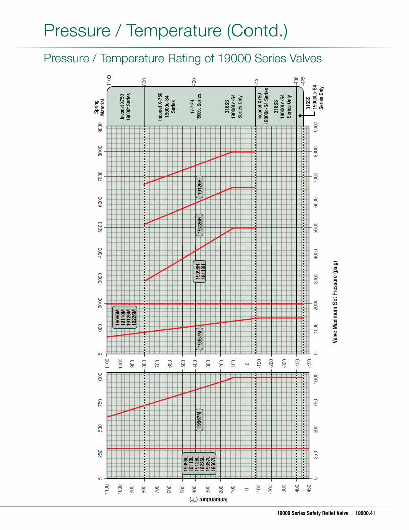
19000 Series Safety Relief Valve | 19000.41
May. 17, 2011
Pressure / Temperature (Contd .)
Pressure / Temperature Rating of 19000 Series Valves
Inco
nel X
750
1900
0t S
erie
s
Inco
nel X
-750
1900
0c-S
4 Se
ries
17-7
PH
1900
0c S
erie
s
316S
S19
000L
c-S4
Serie
s On
ly
Inco
nel X
750
1900
0c-S
4 Se
ries
316S
S19
000L
c-S4
Serie
s On
ly
Temperature (°F)
1100
1000
900
800
700
600
500
400
300
200
100 0
-100
-200
-300
-400
-450
1100
1000
900
800
700
600
500
400
300
200
100 0
-100
-200
-300
-400
-450
1100
800
400
-75
-400
-425
5 25
0 50
0 75
0 10
00
5 25
0 50
0 75
0 10
00
Valv
e M
axim
um S
et P
ress
ure
(psi
g)
5 10
00
2000
30
00
4000
50
00
6000
70
00
8000
90
00
5 10
00
2000
30
00
4000
50
00
6000
70
00
8000
90
00
316S
S19
000L
c-S4
Serie
s On
ly
Sprin
gM
ater
ial
1956
7M19
357M
1922
6H19
126H
1909
6H19
110H
1909
6L19
110L
1912
6L19
226L
1935
7L19
567L
1909
6M19
110M
1912
6M19
226M
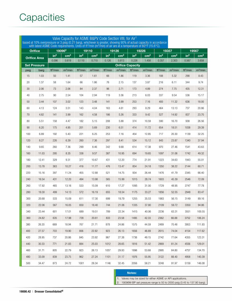
19000.42 | Dresser Consolidated®
May. 17, 2011
Capacities
Valve Capacity for ASME B&PV Code Section VIII, for Air1
based at 10% overpressure or 3 psig (0.21 barg), whichever is greater, showing 90% of actual capacity in accordance with latest ASME Code requirements. Units of ft3/min (m3/min) of air are at a temperature of 60°F (15.6°C).
1. Valves may be sized for either ASME or API applications .
2. 19096M-BP set pressure range is 50 to 2000 psig (3 .45 to 137 .90 barg) .
Notes:
Orifice 190962 19110 19126 19226 19357 19567
Orifice Areain2 cm2 in2 cm2 in2 cm2 in2 cm2 in2 cm2 in2 cm2
0.096 0.619 0.110 0.710 0.126 0.813 0.226 1.458 0.357 2.303 0.567 3.658
Set Pressure Orifice Capacity
psig barg ft3/min m3/min ft3/min m3/min ft3/min m3/min ft3/min m3/min ft3/min m3/min ft3/min m3/min
15 1.03 50 1.41 57 1.61 66 1.86 119 3.36 188 5.32 298 8.43
20 1.37 58 1.64 66 1.86 76 2.15 137 3.87 216 6.11 344 9.74
30 2.06 73 2.06 84 2.37 96 2.71 173 4.89 274 7.75 435 12.31
40 2.75 90 2.54 104 2.94 119 3.36 213 6.03 337 9.54 536 15.17
50 3.44 107 3.02 123 3.48 141 3.99 253 7.16 400 11.32 636 18.00
60 4.13 124 3.51 143 4.04 163 4.61 293 8.29 464 13.13 737 20.86
70 4.82 141 3.99 162 4.58 186 5.26 333 9.42 527 14.92 837 23.70
80 5.51 158 4.47 182 5.15 208 5.88 374 10.59 590 16.70 938 26.56
90 6.20 175 4.95 201 5.69 230 6.51 414 11.72 654 18.51 1038 29.39
100 6.89 192 5.43 221 6.25 253 7.16 454 12.85 717 20.30 1139 32.25
120 8.27 226 6.39 260 7.36 297 8.41 534 15.12 843 23.87 1340 37.94
140 9.65 260 7.36 299 8.46 342 9.68 614 17.38 970 27.46 1541 43.63
160 11.03 295 8.35 338 9.57 387 10.95 694 19.65 1097 31.06 1742 49.32
180 12.41 329 9.31 377 10.67 431 12.20 774 21.91 1223 34.63 1943 55.01
200 13.78 363 10.27 416 11.77 476 13.47 854 24.18 1350 38.22 2144 60.71
220 15.16 397 11.24 455 12.88 521 14.75 934 26.44 1476 41.79 2345 66.40
240 16.54 431 12.20 494 13.98 565 15.99 1015 28.74 1603 45.39 2546 72.09
260 17.92 465 13.16 533 15.09 610 17.27 1095 31.00 1729 48.95 2747 77.78
280 19.30 499 14.13 572 16.19 655 18.54 1175 33.27 1856 52.55 2948 83.47
300 20.68 533 15.09 611 17.30 699 19.79 1255 35.53 1983 56.15 3149 89.16
320 22.06 567 16.05 650 18.40 744 21.06 1335 37.80 2109 59.72 3350 94.86
340 23.44 601 17.01 689 19.51 789 22.34 1415 40.06 2236 63.31 3551 100.55
360 24.82 635 17.98 728 20.61 833 23.58 1495 42.33 2362 66.88 3752 106.24
380 26.20 669 18.94 767 21.71 878 24.86 1575 44.59 2489 70.48 3953 111.93
400 27.57 703 19.90 806 22.82 923 26.13 1656 46.89 2615 74.04 4154 117.62
420 28.95 737 20.86 845 23.92 967 27.38 1736 49.15 2742 77.64 4355 123.31
440 30.33 771 21.83 884 25.03 1012 28.65 1816 51.42 2869 81.24 4556 129.01
460 31.71 805 22.79 923 26.13 1057 29.93 1896 53.68 2995 84.80 4757 134.70
480 33.09 839 23.75 962 27.24 1101 31.17 1976 55.95 3122 88.40 4958 140.39
500 34.47 873 24.72 1001 28.34 1146 32.45 2056 58.21 3248 91.97 5159 146.08
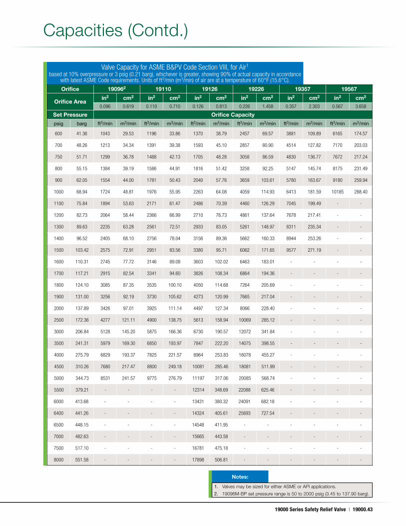
19000 Series Safety Relief Valve | 19000.43
May. 17, 2011
Capacities (Contd .)
Valve Capacity for ASME B&PV Code Section VIII, for Air1
based at 10% overpressure or 3 psig (0.21 barg), whichever is greater, showing 90% of actual capacity in accordance with latest ASME Code requirements. Units of ft3/min (m3/min) of air are at a temperature of 60°F (15.6°C).
Orifice 190962 19110 19126 19226 19357 19567
Orifice Areain2 cm2 in2 cm2 in2 cm2 in2 cm2 in2 cm2 in2 cm2
0.096 0.619 0.110 0.710 0.126 0.813 0.226 1.458 0.357 2.303 0.567 3.658
Set Pressure Orifice Capacity
psig barg ft3/min m3/min ft3/min m3/min ft3/min m3/min ft3/min m3/min ft3/min m3/min ft3/min m3/min
600 41.36 1043 29.53 1196 33.86 1370 38.79 2457 69.57 3881 109.89 6165 174.57
700 48.26 1213 34.34 1391 39.38 1593 45.10 2857 80.90 4514 127.82 7170 203.03
750 51.71 1299 36.78 1488 42.13 1705 48.28 3058 86.59 4830 136.77 7672 217.24
800 55.15 1384 39.19 1586 44.91 1816 51.42 3258 92.25 5147 145.74 8175 231.49
900 62.05 1554 44.00 1781 50.43 2040 57.76 3659 103.61 5780 163.67 9180 259.94
1000 68.94 1724 48.81 1976 55.95 2263 64.08 4059 114.93 6413 181.59 10185 288.40
1100 75.84 1894 53.63 2171 61.47 2486 70.39 4460 126.29 7045 199.49 - -
1200 82.73 2064 58.44 2366 66.99 2710 76.73 4861 137.64 7678 217.41 - -
1300 89.63 2235 63.28 2561 72.51 2933 83.05 5261 148.97 8311 235.34 - -
1400 96.52 2405 68.10 2756 78.04 3156 89.36 5662 160.33 8944 253.26 - -
1500 103.42 2575 72.91 2951 83.56 3380 95.71 6062 171.65 9577 271.19 - -
1600 110.31 2745 77.72 3146 89.08 3603 102.02 6463 183.01 - - - -
1700 117.21 2915 82.54 3341 94.60 3826 108.34 6864 194.36 - - - -
1800 124.10 3085 87.35 3535 100.10 4050 114.68 7264 205.69 - - - -
1900 131.00 3256 92.19 3730 105.62 4273 120.99 7665 217.04 - - - -
2000 137.89 3426 97.01 3925 111.14 4497 127.34 8066 228.40 - - - -
2500 172.36 4277 121.11 4900 138.75 5613 158.94 10069 285.12 - - - -
3000 206.84 5128 145.20 5875 166.36 6730 190.57 12072 341.84 - - - -
3500 241.31 5979 169.30 6850 193.97 7847 222.20 14075 398.55 - - - -
4000 275.79 6829 193.37 7825 221.57 8964 253.83 16078 455.27 - - - -
4500 310.26 7680 217.47 8800 249.18 10081 285.46 18081 511.99 - - - -
5000 344.73 8531 241.57 9775 276.79 11197 317.06 20085 568.74 - - - -
5500 379.21 - - - - 12314 348.69 22088 625.46 - - - -
6000 413.68 - - - - 13431 380.32 24091 682.18 - - - -
6400 441.26 - - - - 14324 405.61 25693 727.54 - - - -
6500 448.15 - - - - 14548 411.95 - - - - - -
7000 482.63 - - - - 15665 443.58 - - - - - -
7500 517.10 - - - - 16781 475.18 - - - - - -
8000 551.58 - - - - 17898 506.81 - - - - - -
1. Valves may be sized for either ASME or API applications .
2. 19096M-BP set pressure range is 50 to 2000 psig (3 .45 to 137 .90 barg) .
Notes:
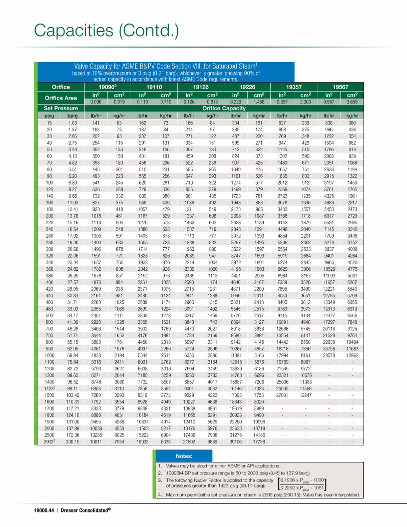
19000.44 | Dresser Consolidated®
May. 17, 2011
1. Valves may be sized for either ASME or API applications .
2. 19096M-BP set pressure range is 50 to 2000 psig (3 .45 to 137 .9 barg) .
3. The following Napier Factor is applied to the capacity of pressures greater than 1423 psig (98 .11 barg):
4. Maximum permissible set pressure on steam is 2903 psig (200 .15) . Value has been interpolated .
Notes:
Capacities (Contd .)
0 .1906 x Ppsia - 1000[ ]0 .2292 x Ppsia - 1061
Valve Capacity for ASME B&PV Code Section VIII, for Saturated Steam1
based at 10% overpressure or 3 psig (0.21 barg), whichever is greater, showing 90% of actual capacity in accordance with latest ASME Code requirements.
Orifice 190962 19110 19126 19226 19357 19567
Orifice Area in2 cm2 in2 cm2 in2 cm2 in2 cm2 in2 cm2 in2 cm2
0.096 0.619 0.110 0.710 0.126 0.813 0.226 1.458 0.357 2.303 0.567 3.658Set Pressure Orifice Capacitypsig barg lb/hr kg/hr lb/hr kg/hr lb/hr kg/hr lb/hr kg/hr lb/hr kg/hr lb/hr kg/hr15 1.03 141 63 162 73 186 84 334 151 527 239 838 38020 1.37 163 73 187 84 214 97 385 174 608 275 966 43830 2.06 207 93 237 107 271 122 487 220 769 348 1222 55440 2.75 254 115 291 131 334 151 599 271 947 429 1504 68250 3.44 302 136 346 156 397 180 712 322 1125 510 1786 81060 4.13 350 158 401 181 459 208 824 373 1302 590 2068 93870 4.82 398 180 456 206 522 236 937 425 1480 671 2351 106680 5.51 445 201 510 231 585 265 1049 475 1657 751 2633 119490 6.20 493 223 565 256 647 293 1161 526 1835 832 2915 1322100 6.89 541 245 620 281 710 322 1274 577 2012 912 3197 1450120 8.27 636 288 729 330 835 378 1499 679 2368 1074 3761 1705140 9.65 732 332 839 380 961 435 1723 781 2723 1235 4325 1961160 11.03 827 375 948 430 1086 492 1948 883 3078 1396 4889 2217180 12.41 923 418 1057 479 1211 549 2173 985 3433 1557 5453 2473200 13.78 1018 461 1167 529 1337 606 2398 1087 3788 1718 6017 2729220 15.16 1114 505 1276 578 1462 663 2623 1189 4143 1879 6581 2985240 16.54 1209 548 1386 628 1587 719 2848 1291 4498 2040 7145 3240260 17.92 1305 591 1495 678 1713 777 3072 1393 4854 2201 7709 3496280 19.30 1400 635 1605 728 1838 833 3297 1495 5209 2362 8273 3752300 20.68 1496 678 1714 777 1963 890 3522 1597 5564 2523 8837 4008320 22.06 1591 721 1823 826 2089 947 3747 1699 5919 2684 9401 4264340 23.44 1687 765 1933 876 2214 1004 3972 1801 6274 2845 9965 4520360 24.82 1782 808 2042 926 2339 1060 4196 1903 6629 3006 10529 4775380 26.20 1878 851 2152 976 2465 1118 4421 2005 6984 3167 11093 5031400 27.57 1973 894 2261 1025 2590 1174 4646 2107 7339 3328 11657 5287420 28.95 2069 938 2371 1075 2715 1231 4871 2209 7695 3490 12221 5543440 30.33 2164 981 2480 1124 2841 1288 5096 2311 8050 3651 12785 5799460 31.71 2260 1025 2589 1174 2966 1345 5321 2413 8405 3812 13349 6055480 33.09 2355 1068 2699 1224 3091 1402 5545 2515 8760 3973 13913 6310500 34.47 2451 1111 2808 1273 3217 1459 5770 2617 9115 4134 14477 6566600 41.36 2928 1328 3355 1521 3843 1743 6894 3127 10891 4940 17297 7845700 48.26 3406 1544 3902 1769 4470 2027 8018 3636 12666 5745 20118 9125750 51.71 3644 1652 4176 1894 4784 2169 8580 3891 13554 6147 21528 9764800 55.15 3883 1761 4450 2018 5097 2311 9142 4146 14442 6550 22938 10404900 62.05 4361 1978 4997 2266 5724 2596 10267 4657 16218 7356 25758 116831000 68.94 4838 2194 5544 2514 6350 2880 11391 5166 17994 8161 28578 129621100 75.84 5316 2411 6091 2762 6977 3164 12515 5676 19769 8967 - -1200 82.73 5793 2627 6638 3010 7604 3449 13639 6186 21545 9772 - -1300 89.63 6271 2844 7185 3259 8230 3733 14763 6696 23321 10578 - -1400 96.52 6748 3060 7732 3507 8857 4017 15887 7206 25096 11383 - -14233 98.11 6858 3110 7858 3564 9001 4082 16146 7323 25505 11568 - -1500 103.42 7260 3293 8319 3773 9529 4322 17093 7753 27001 12247 - -1600 110.31 7792 3534 8928 4049 10227 4638 18343 8320 - - - -1700 117.21 8333 3779 9549 4331 10938 4961 19619 8899 - - - -1800 124.10 8888 4031 10184 4619 11665 5291 20923 9490 - - - -1900 131.00 9455 4288 10834 4914 12410 5629 22260 10096 - - - -2000 137.89 10039 4553 11503 5217 13176 5976 23633 10719 - - - -2500 172.36 13285 6025 15222 6904 17436 7908 31275 14186 - - - -29034 200.15 16611 7534 19033 8633 21802 9889 39106 17738 - - - -
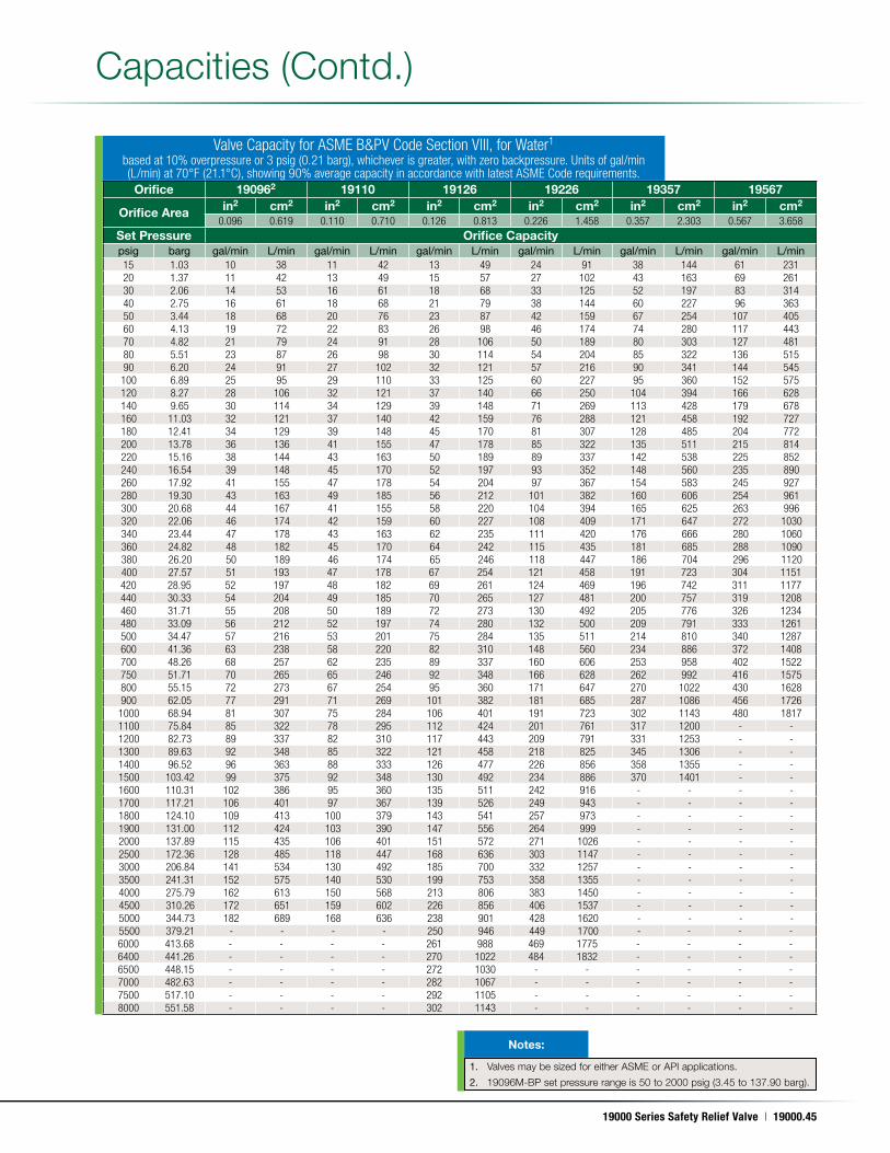
19000 Series Safety Relief Valve | 19000.45
May. 17, 2011
Capacities (Contd .)
Valve Capacity for ASME B&PV Code Section VIII, for Water1
based at 10% overpressure or 3 psig (0.21 barg), whichever is greater, with zero backpressure. Units of gal/min (L/min) at 70°F (21.1°C), showing 90% average capacity in accordance with latest ASME Code requirements. Orifice 190962 19110 19126 19226 19357 19567
Orifice Area in2 cm2 in2 cm2 in2 cm2 in2 cm2 in2 cm2 in2 cm2
0.096 0.619 0.110 0.710 0.126 0.813 0.226 1.458 0.357 2.303 0.567 3.658Set Pressure Orifice Capacitypsig barg gal/min L/min gal/min L/min gal/min L/min gal/min L/min gal/min L/min gal/min L/min15 1.03 10 38 11 42 13 49 24 91 38 144 61 23120 1.37 11 42 13 49 15 57 27 102 43 163 69 26130 2.06 14 53 16 61 18 68 33 125 52 197 83 31440 2.75 16 61 18 68 21 79 38 144 60 227 96 36350 3.44 18 68 20 76 23 87 42 159 67 254 107 40560 4.13 19 72 22 83 26 98 46 174 74 280 117 44370 4.82 21 79 24 91 28 106 50 189 80 303 127 48180 5.51 23 87 26 98 30 114 54 204 85 322 136 51590 6.20 24 91 27 102 32 121 57 216 90 341 144 545100 6.89 25 95 29 110 33 125 60 227 95 360 152 575120 8.27 28 106 32 121 37 140 66 250 104 394 166 628140 9.65 30 114 34 129 39 148 71 269 113 428 179 678160 11.03 32 121 37 140 42 159 76 288 121 458 192 727180 12.41 34 129 39 148 45 170 81 307 128 485 204 772200 13.78 36 136 41 155 47 178 85 322 135 511 215 814220 15.16 38 144 43 163 50 189 89 337 142 538 225 852240 16.54 39 148 45 170 52 197 93 352 148 560 235 890260 17.92 41 155 47 178 54 204 97 367 154 583 245 927280 19.30 43 163 49 185 56 212 101 382 160 606 254 961300 20.68 44 167 41 155 58 220 104 394 165 625 263 996320 22.06 46 174 42 159 60 227 108 409 171 647 272 1030340 23.44 47 178 43 163 62 235 111 420 176 666 280 1060360 24.82 48 182 45 170 64 242 115 435 181 685 288 1090380 26.20 50 189 46 174 65 246 118 447 186 704 296 1120400 27.57 51 193 47 178 67 254 121 458 191 723 304 1151420 28.95 52 197 48 182 69 261 124 469 196 742 311 1177440 30.33 54 204 49 185 70 265 127 481 200 757 319 1208460 31.71 55 208 50 189 72 273 130 492 205 776 326 1234480 33.09 56 212 52 197 74 280 132 500 209 791 333 1261500 34.47 57 216 53 201 75 284 135 511 214 810 340 1287600 41.36 63 238 58 220 82 310 148 560 234 886 372 1408700 48.26 68 257 62 235 89 337 160 606 253 958 402 1522750 51.71 70 265 65 246 92 348 166 628 262 992 416 1575800 55.15 72 273 67 254 95 360 171 647 270 1022 430 1628900 62.05 77 291 71 269 101 382 181 685 287 1086 456 17261000 68.94 81 307 75 284 106 401 191 723 302 1143 480 18171100 75.84 85 322 78 295 112 424 201 761 317 1200 - -1200 82.73 89 337 82 310 117 443 209 791 331 1253 - -1300 89.63 92 348 85 322 121 458 218 825 345 1306 - -1400 96.52 96 363 88 333 126 477 226 856 358 1355 - -1500 103.42 99 375 92 348 130 492 234 886 370 1401 - -1600 110.31 102 386 95 360 135 511 242 916 - - - -1700 117.21 106 401 97 367 139 526 249 943 - - - -1800 124.10 109 413 100 379 143 541 257 973 - - - -1900 131.00 112 424 103 390 147 556 264 999 - - - -2000 137.89 115 435 106 401 151 572 271 1026 - - - -2500 172.36 128 485 118 447 168 636 303 1147 - - - -3000 206.84 141 534 130 492 185 700 332 1257 - - - -3500 241.31 152 575 140 530 199 753 358 1355 - - - -4000 275.79 162 613 150 568 213 806 383 1450 - - - -4500 310.26 172 651 159 602 226 856 406 1537 - - - -5000 344.73 182 689 168 636 238 901 428 1620 - - - -5500 379.21 - - - - 250 946 449 1700 - - - -6000 413.68 - - - - 261 988 469 1775 - - - -6400 441.26 - - - - 270 1022 484 1832 - - - -6500 448.15 - - - - 272 1030 - - - - - -7000 482.63 - - - - 282 1067 - - - - - -7500 517.10 - - - - 292 1105 - - - - - -8000 551.58 - - - - 302 1143 - - - - - -
1. Valves may be sized for either ASME or API applications .
2. 19096M-BP set pressure range is 50 to 2000 psig (3 .45 to 137 .90 barg) .
Notes:
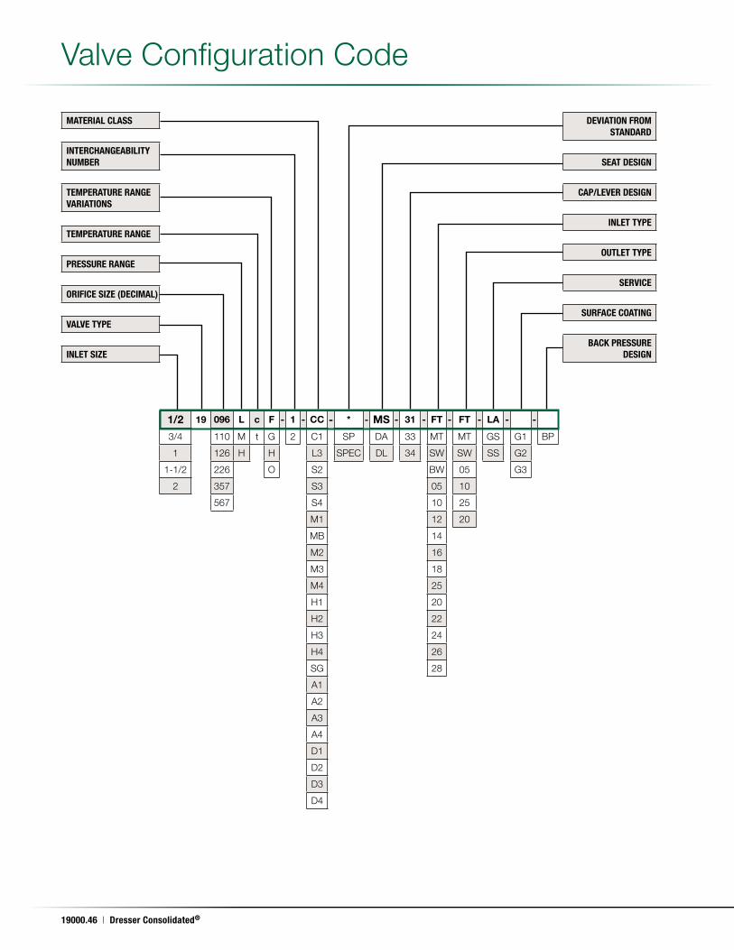
19000.46 | Dresser Consolidated®
May. 17, 2011
MATERIAL CLASS
INTERCHANGEABILITY NUMBER
TEMPERATURE RANGE VARIATIONS
TEMPERATURE RANGE
PRESSURE RANGE
ORIFICE SIZE (DECIMAL)
VALVE TYPE
INLET SIZE
DEVIATION FROM STANDARD
SEAT DESIGN
CAP/LEVER DESIGN
INLET TYPE
OUTLET TYPE
SERVICE
SURFACE COATING
BACK PRESSURE DESIGN
Valve Configuration Code
1/2 19 096 L c F - 1 - CC - * - MS - 31 - FT - FT - LA - -
3/4 110 M t G 2 C1 SP DA 33 MT MT GS G1 BP
1 126 H H L3 SPEC DL 34 SW SW SS G2
1-1/2 226 O S2 BW 05 G3
2 357 S3 05 10
567 S4 10 25
M1 12 20
MB 14
M2 16
M3 18
M4 25
H1 20
H2 22
H3 24
H4 26
SG 28
A1
A2
A3
A4
D1
D2
D3
D4
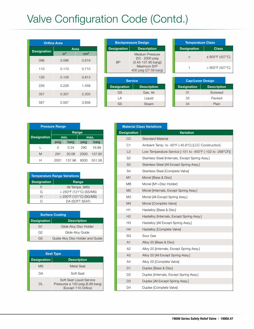
19000 Series Safety Relief Valve | 19000.47
May. 17, 2011
Temperature Class
Temperature Range Variations
Surface Coating
Material Class Variations
Designation Class
c ≤ 800°F (427°C)
t > 800°F (427°C)
Designation Range
F All Temps . (MS)G > 250°F (121°C) (SS/MS)H > 250°F (121°C) (SG/MS)O DA (SOFT SEAT)
Designation Description
G1 Glide Aloy Disc Holder
G2 Glide Aloy Guide
G3 Guide Aloy Disc Holder and Guide
Designation Variation
CC Standard Material
C1 Ambient Temp . to -50°F (-45 .6°C) [LCC Construction]
L3 Low Temperature Service [-151 to -450°F (-102 to -268°CF)]
S2 Stainless Steel [Internals, Except Spring Assy .]
S3 Stainless Steel [All Except Spring Assy .]
S4 Stainless Steel [Complete Valve]
M1 Monel [Base & Disc]
MB Monel [M1+Disc Holder]
M2 Monel [Internals, Except Spring Assy .]
M3 Monel [All Except Spring Assy .]
M4 Monel [Complete Valve]
H1 Hastelloy [Base & Disc]
H2 Hastelloy [Internals, Except Spring Assy .]
H3 Hastelloy [All Except Spring Assy .]
H4 Hastelloy [Complete Valve]
SG Sour Gas
A1 Alloy 20 [Base & Disc]
A2 Alloy 20 [Internals, Except Spring Assy .]
A3 Alloy 20 [All Except Spring Assy .]
A4 Alloy 20 [Complete Valve]
D1 Duplex [Base & Disc]
D2 Duplex [Internals, Except Spring Assy .]
D3 Duplex [All Except Spring Assy .]
D4 Duplex [Complete Valve]
Backpressure Design
Designation Description
BP
Medium Pressure [50 - 2000 psig
(3 .45-137 .90 barg)] Maximum B/P
400 psig (27 .58 barg)
Pressure Range
Orifice Area
DesignationRange
min. max.psig barg psig barg
L 5 0 .34 290 19 .99
M 291 20 .06 2000 137 .90
H 2001 137 .96 8000 551 .58
DesignationArea
in2 cm2
096 0 .096 0 .619
110 0 .110 0 .710
126 0 .126 0 .813
226 0 .226 1 .458
357 0 .357 2 .303
567 0 .567 3 .658
Cap/Lever Design
Designation Description
31 Screwed
33 Packed
34 Plain
Service
Designation Description
GS Gas, Air
LA Liquid
SS Steam
Seat Type
Designation Description
MS Metal Seat
DA Soft Seat
DLSoft Seat Liquid Service
Pressures ≤ 100 psig (6 .89 barg) (Except 110 Orifice)
Valve Configuration Code (Contd .)
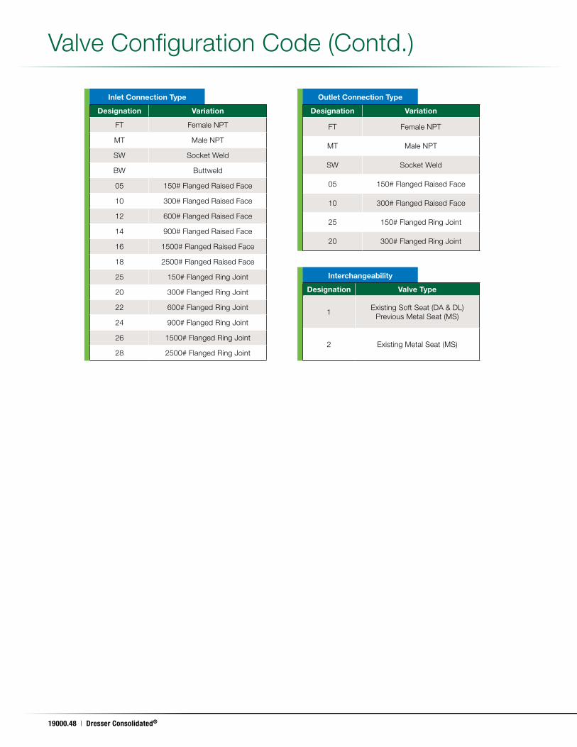
19000.48 | Dresser Consolidated®
May. 17, 2011
Inlet Connection Type Outlet Connection Type
Interchangeability
Designation Variation
FT Female NPT
MT Male NPT
SW Socket Weld
BW Buttweld
05 150# Flanged Raised Face
10 300# Flanged Raised Face
12 600# Flanged Raised Face
14 900# Flanged Raised Face
16 1500# Flanged Raised Face
18 2500# Flanged Raised Face
25 150# Flanged Ring Joint
20 300# Flanged Ring Joint
22 600# Flanged Ring Joint
24 900# Flanged Ring Joint
26 1500# Flanged Ring Joint
28 2500# Flanged Ring Joint
Designation Variation
FT Female NPT
MT Male NPT
SW Socket Weld
05 150# Flanged Raised Face
10 300# Flanged Raised Face
25 150# Flanged Ring Joint
20 300# Flanged Ring Joint
Designation Valve Type
1Existing Soft Seat (DA & DL)
Previous Metal Seat (MS)
2 Existing Metal Seat (MS)
Valve Configuration Code (Contd .)
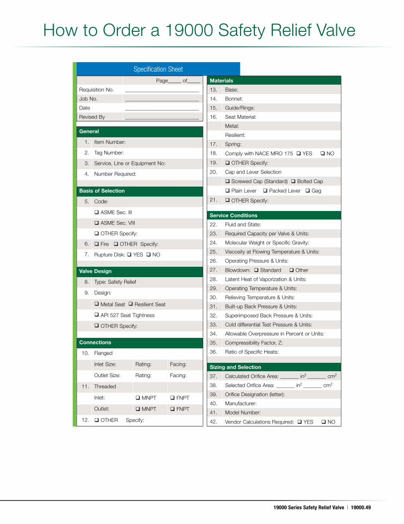
19000 Series Safety Relief Valve | 19000.49
May. 17, 2011
How to Order a 19000 Safety Relief Valve
Specification Sheet
Page_____ of_____
Requisition No . ____________________________
Job No . ____________________________
Date ____________________________
Revised By ____________________________
General
1 . Item Number:
2 . Tag Number:
3 . Service, Line or Equipment No:
4 . Number Required:
Basis of Selection
5 . Code:
ASME Sec . III
ASME Sec . VIII
OTHER Specify:
6 . Fire OTHER Specify:
7 . Rupture Disk: YES NO
Valve Design
8 . Type: Safety Relief
9 . Design:
Metal Seat Resilient Seat
API 527 Seat Tightness
OTHER Specify:
Connections
10 . Flanged
Inlet Size: Rating: Facing:
Outlet Size: Rating: Facing:
11 . Threaded
Inlet: MNPT FNPT
Outlet: MNPT FNPT
12 . OTHER Specify:
Materials
13 . Base:
14 . Bonnet:
15 . Guide/Rings:
16 . Seat Material:
Metal:
Resilient:
17 . Spring:
18 . Comply with NACE MRO 175 YES NO
19 . OTHER Specify:
20 . Cap and Lever Selection
Screwed Cap (Standard) Bolted Cap
Plain Lever Packed Lever Gag
21 . OTHER Specify:
Service Conditions
22 . Fluid and State:
23 . Required Capacity per Valve & Units:
24 . Molecular Weight or Specific Gravity:
25 . Viscosity at Flowing Temperature & Units:
26 . Operating Pressure & Units:
27 . Blowdown: Standard Other
28 . Latent Heat of Vaporization & Units:
29 . Operating Temperature & Units:
30 . Relieving Temperature & Units:
31 . Built-up Back Pressure & Units:
32 . Superimposed Back Pressure & Units:
33 . Cold differential Test Pressure & Units:
34 . Allowable Overpressure in Percent or Units:
35 . Compressibility Factor, Z:
36 . Ratio of Specific Heats:
Sizing and Selection
37 . Calculated Orifice Area: _______ in2 _______ cm2
38 . Selected Orifice Area: _______ in2 _______ cm2
39 . Orifice Designation (letter):
40 . Manufacturer:
41 . Model Number:
42 . Vendor Calculations Required: YES NO