19 modelling of interfacial heat transfer … of interfa… · die casting process and presence of...
TRANSCRIPT

International Journal of Mechanical Engineering and Technology (IJMET), ISSN 0976 – 6340(Print),
ISSN 0976 – 6359(Online) Volume 1, Number 1, July - Aug (2010), © IAEME
253
MODELLING OF INTERFACIAL HEAT TRANSFER
COEFFICIENT AND EXPERIMENTAL VERIFICATION
FOR GRAVITY DIE CASTING OF ALUMINIUM ALLOYS.
Cherian Paul
Assistant Professor
Department of Mechanical Engineering
SaintGITS College of Engineering, Kottayam, Kerala
Email: [email protected]
Parvathy Venugopal
Assistant Professor
Department of Mechanical Engineering
SaintGITS College of Engineering, Kottayam, Kerala
Email: [email protected]
ABSTRACT:
Interfacial heat-transfer coefficient has been measured during the solidification of
Aluminium alloys using permanent molds and solidification simulation technique is
being proposed in this thesis. The principal resistances to heat transfer across the casting-
die interface is the resistance of a layer of gas (assumed to be air), trapped between the
die and casting surfaces by virtue of their roughness and because of the solidification
shrinkage property exhibited during casting process and the thermal resistance offered by
the surface coating applied on the die. A Finite element simulation technique for gravity
die casting process is developed. This simulates the temperature at various locations in
die casting process and presence of hot spots, (i.e., a location in a casting that solidifies
last); in turn helps in placing the riser at the exact locations, there by increasing the
efficiency of die design. Several experiments were conducted by changing the core types
and using die coats to determine the heat transfer coefficient values by measuring the
surface roughness values of die and casting. The temperature at outside die surface is
measured and compared with the simulated results. These results were found to agree
with the experimentally determined temperatures.
International Journal of Mechanical Engineering
and Technology (IJMET), ISSN 0976 – 6340(Print)
ISSN 0976 – 6359(Online) Volume 1
Number 1, July - Aug (2010), pp. 253-274
© IAEME, http://www.iaeme.com/ijmet.html
IJMET
© I A E M E

International Journal of Mechanical Engineering and Technology (IJMET), ISSN 0976 – 6340(Print),
ISSN 0976 – 6359(Online) Volume 1, Number 1, July - Aug (2010), © IAEME
254
Index Terms: Interfacial heat transfer coefficient, dycote, sand core, plaster core,
ANSYS
1. INTRODUCTION
MODELING of solidification can be of great benefit in improving the efficiency
of the casting process by showing how solidification defects such as shrinkage can be
avoided and by showing how smaller feeding systems can be used, improving the casting
yield. Good models require an accurate calculation of the changing temperature field in
the casting and this requires good data on the thermophysical properties of the materials
involved, but also a good knowledge of the initial conditions (the initial temperature
field) and the boundary conditions (often described by a heat-transfer coefficient).The
research described here was aimed at understanding the heat-transfer mechanisms at the
interface between a casting and its die in the gravity and low-pressure die casting of Al
alloys. In these processes, a layer of a porous refractory material is usually applied to the
die cavities. This reduces heat transfer between the cast liquid alloy and the die,
promoting filling of the cavity. It also controls the solidification rate in different areas of
the die; for example, the running and feeding parts of the die can often have a much
thicker coating applied to them to locally increase insulation. The coating also improves
the life of the die by reducing the thermal shock experienced and prevents the cast alloy
from soldering to the die material. Its further roles are to vent trapped air from the die
cavity and, in some cases, lubricate the release of the casting from the die. Studies of heat
transfer in gravity die casting process are important phenomena which will influence the
solidification process. Heat transfer between the die and casting is mainly restricted by
thin layer of air presented by virtue of surface roughness and solidification shrinkage.
Better understanding of interfacial heat transfer coefficients, boundary conditions and
material properties (density, thermal conductivity, and specific heat) will help the
designers for effective implementation of the simulation method in the riser design.
Studies have been reported on the measurement of interfacial heat transfer
coefficient and in general, a wide range has been reported. A narrow range of values is
more appropriate to model the solidification behavior accurately. This work is aimed at
finding out the interfacial heat transfer coefficients, at the interface between a casting and
its die in gravity die casting of Al alloys under various situations and to propose a shorter

International Journal of Mechanical Engineering and Technology (IJMET), ISSN 0976 – 6340(Print),
ISSN 0976 – 6359(Online) Volume 1, Number 1, July - Aug (2010), © IAEME
255
range of heat transfer coefficient values. For this, a Finite element simulation technique
for gravity die casting process has to be developed, which should simulate the
temperature at various locations in die casting process and presence of hot spots, (i.e., a
location in a casting that solidifies last); in turn helps in placing the riser at the exact
locations, there by increasing the efficiency of die design. To validate the results obtained
by simulation, experiment has to be conducted to find the heat transfer coefficient in
gravity die casting process.
2. PROBLEM DEFINITION AND OBJECTIVES
It has been reported in the literature that the interfacial heat transfer coefficients
can vary in a range of 500-16500 W/m2K [2], which is wide range for designers to select
the appropriate values for simulating die casting process. Use of such wide range of
values in casting simulation will lead to inconsistent and in accurate results. Therefore it
is difficult to design risers properly using simulation. In this work experiments has been
conducted to narrow down the range of heat transfer coefficient values.
The main objectives are:
• Estimate the interfacial heat transfer coefficient using surface roughness and coatings
of die.
• Measure temperature variation with time (cooling curves) at specific locations in the
die and casting.
• Simulate the temperature profile using the modeled values of interfacial heat transfer
coefficient as an input parameter in solving heat transfer equation.
• Compare the simulated cooling curves with the experimentally measured curves.
3. ESTIMATION OF INTERFACIAL HEAT TRANSFER
COEFFICIENT
The procedure to estimate the interfacial heat transfer coefficient is discussed below.
3.1 Model of the interfacial heat transfer coefficient:
The interface of the die and casting will be as shown in Figure 3.1

International Journal of Mechanical Engineering and Technology (IJMET), ISSN 0976 – 6340(Print),
ISSN 0976 – 6359(Online) Volume 1, Number 1, July - Aug (2010), © IAEME
256
Figure 3.1 Surface patterns between casting and mould interface
At some time, t, after pouring a pure metal into an insulating mold (sand or ceramic) at
some pouring temperature the temperature along a line perpendicular to the mold - metal
interface would be expected appear as shown in Figure 3.2
Figure 3.2 Heat Transfer Pattern in Permanent Molds
Drop in temperature at mold and casting interface is mainly because of
• Resistance to heat offered by air gap presented in between die and casting.
� The resistance offered by the coatings applied on die surface. It is a usual practice
to apply coating on the die surface.
Air gap between the die and casting interface is formed because of
a) Solidification shrinkage of casting.
b) Surface roughness of the die and casting.
Figure 3.3 below describes the various elements for air gap formation
Figure 3.3 Casting and Die interface
These thermal resistances are evaluated by measurement of the coating thermal
conductivity and determination of the thickness of the applied coatings and the thickness
of the layer of air between the coating and casting surfaces. This system can be equated

International Journal of Mechanical Engineering and Technology (IJMET), ISSN 0976 – 6340(Print),
ISSN 0976 – 6359(Online) Volume 1, Number 1, July - Aug (2010), © IAEME
257
to the electrical resistance system with two resistances in series which is shown in Figure
3.4.
Figure 3.4 Electrical resistance equivalent system for resistances in series
These thermal resistances are in series and were summed to determine the overall
thermal resistance.
resisttotal = resistcoat + resista
The heat transfer coefficients being reciprocal of the thermal resistance
h = (resistcoat + resista)-1
3.2 Coating resistance:
It was assumed that the coating surface could be described as a simple saw-tooth
profile, as shown in Figure 3.5
Figure 3.5 Insulating Coating on a Flat Substrate
Case i
The white coating was sprayed onto the die surface assumed to be flat. In this
case, it was assumed that the coating thickness measuring device rested on the top of the
highest peaks of the coating, and therefore was measuring distance xmax in Fig 4.3. The
mean thickness of the white coating (xmean) therefore was determined as this measured
thickness, minus half of the value of Ry, the maximum peak-to-valley height. The
thermal resistance through the die coating (resistcoat) could then be calculated using the
following expression:
(3.3)

International Journal of Mechanical Engineering and Technology (IJMET), ISSN 0976 – 6340(Print),
ISSN 0976 – 6359(Online) Volume 1, Number 1, July - Aug (2010), © IAEME
258
Caseii
When the coating was sprayed onto a grit-blasted surface, the rough nature of the
substrate had to be taken into account as shown in Figure 4.6
Figure 3.6 Surface Profile of the Coating and Die Surfaces
It was assumed that the grit blasted die surface also had a saw-tooth profile and
the mean peak-to-valley height was denoted Rz(sub), and the maximum peak-to-valley
height denoted Ry(sub). The coating thickness measuring device was first zeroed on an
uncoated grit-blasted substrate, and therefore, the reference plane was the plane of the
highest peaks of the substrate. However, the valleys of the substrate were full of coating
material, so the reference plane lay above a coating thickness equivalent to 0.5Ry(sub).
The coating thickness measuring device was then placed on the surface of the coated
substrate and the resulting measured coating thickness was therefore from the highest
peaks of the coating to the reference plane, a distance denoted xmax. However, half of this
measured value was air (from the valleys of the coating surface). Therefore, the true
mean coating thickness was estimated as
)()(max 5.05.0 coatysuby RRxthickness −+=
The thermal resistance offered by the chromia coating was therefore equal to
(3.5)
3.3 Air resistance:
The gas in the voids between the rough casting and die surfaces would be
expected to offer a thermal resistance depending upon its thermal conductivity and
thickness, which depended on how the two rough surfaces were in contact.
In this case, the two surfaces were assumed to be in random contact as shown in
Figure 3.6, as a result of lateral thermal contraction of the casting surface and lateral
thermal expansion of the surface of the die. The two rough surfaces were equated to a
single sum rough surface in contact with a plane surface, and the roughness of this sum
rough surface was estimated by

International Journal of Mechanical Engineering and Technology (IJMET), ISSN 0976 – 6340(Print),
ISSN 0976 – 6359(Online) Volume 1, Number 1, July - Aug (2010), © IAEME
259
shrinkagecastZdieZZ RRRR ++=Σ )(2
)(2
)( (3.6)
Reference: C.P. Hallam and W.D. Griffiths., “A Model of the Interfacial Heat- Transfer
coefficient for the Aluminum Gravity Die-Casting Process”, Metallurgical and Materials
Transactions B, vol 35B, pp. 1-15.
Where Rz(die) is surface roughness value of die, Rz(cast) is surface roughness value
of casting and Rshrinkage is the gap formed by solidification shrinkage. Rz(Σ) is the mean
peak-to-valley distance of the sum rough surface. An equivalent mean gap between the
two surfaces therefore was estimated to be 0.5Rz(Σ). Heat transfer through this interfacial
layer of gas (assumed to be air) was considered to be due to conduction only; heat
transfer by radiation and convection would be negligible. The thermal resistance of this
air layer therefore was estimated by
a
Z
ak
Rresist
)(5.0 Σ= (3.7)
Where ka is the thermal conductivity of air.
4. EXPERIMENTAL DETAILS
4.1 Equipment description:
The equipment needed for conducting experiments are (i) melting furnace,
(ii) thermocouples and (iii) steel die and these items are described below.
4.1.1 Melting furnace:
For melting of the aluminium, muffle furnace is used. The max temperature limit
for this muffle furnace is 12000C and the working temperature is 1080
0C. Before melting
the aluminium the crucible is pre heated to 4500C in order to eliminate moisture content
present in the crucible and to avoid the entrapped gases. Then the aluminium scrap of
IS63400 is charged in to the crucible for melting and is superheated to 7800C.
Figure 4.1 Melting Furnace

International Journal of Mechanical Engineering and Technology (IJMET), ISSN 0976 – 6340(Print),
ISSN 0976 – 6359(Online) Volume 1, Number 1, July - Aug (2010), © IAEME
260
4.1.2 Thermocouple:
A K-type mineral insulated thermocouple is used to measure the die temperature.
The maximum temperature that can be measured by the thermocouple is 14000C and a
digital reading unit shown in Figure is used to read the temperature.
Figure 4.2 Thermocouple
4.1.3 The Die:
Cast iron blocks are bought and are machined to required dimensions for making
the die. The die assembly consists of One Base plate 350x250x25 mm3, two Side plates
200x80x25 mm3 each, two end plates 220x80x25 mm
3 each and two half inch MS bolts
for fastening them. Two more equipments used are the crucible made of graphite and the
tongs made from MS rods. These equipments are shown below in Figure 4.3
Figure 4.3 Die Arrangement Used for Experimentation
ground level have been identified for wind power development. Six handbooks on “Wind
Energy Resource Survey in India” have so far been published covering 208 sites. The
seventh volume of Handbook covering wind data for 26 stations is ready for publication.
It is also proposed to prepare a Wind Atlas for India, which will give the overall potential
in various States and identify high windy areas and specific sites for setting up wind
power projects.
Crucibl
Tong Die

International Journal of Mechanical Engineering and Technology (IJMET), ISSN 0976 – 6340(Print),
ISSN 0976 – 6359(Online) Volume 1, Number 1, July - Aug (2010), © IAEME
261
4.2 Material Used: Short descriptions of the materials used for conducting the experiments are given below.
4.2.1 Aluminium ingot:
IS63400 grade aluminium is used to make the melt and the composition of the
alloy used is given below in table 4.1
Table 4.1 Composition of aluminium
Element Weight %
Copper 0 – 0.1
Magnesium 0.4 - 0.9
Silicon 0.3 – 0.7
Iron 0 – 0.3
Manganese 0 – 0.4
Other elements like titanium and grain refining elements will be of 0.4%
4.2.2 Dycote 140:
Castings obtained by GDC should be
i. Metallurgical sound.
ii. Having good surface finish.
iii. Easily and rapidly produced
To achieve this, the die must be coated. Usually the dycotes are of 2 types,
insulating and lubricating coatings. Insulating coating materials contain blends of
insulation minerals such as talc, mica, titanium dioxide, alumina etc. In this experimental
work, we are using a insulating coating material dycote 140. Dycote 140 is an off white
paste with mixing ratio of 3-5 volume of soft water to 1 volume of paste. It is the
standard; general purpose dressing used extensively in all sectors and gives a medium to
fine surface finish. The major components of dycote 140 are mica, talc and sodium
silicate
4.2.3 Sand core:
The molding sand is used for making sand core. Molding sand is actually silica
sand mixed with some additives like bentonite of about 5-10% (depending on the amount
of silica present) coal dust 1-1.2% and 5-7% of water. A core of size 200x80x30 mm3
was made for the experimental work. The sand core made is shown below in Figure 4.5

International Journal of Mechanical Engineering and Technology (IJMET), ISSN 0976 – 6340(Print),
ISSN 0976 – 6359(Online) Volume 1, Number 1, July - Aug (2010), © IAEME
262
Figure 4.5 Sand core
4.2.4 Plaster of paris core:
Experiment was conducted using a plaster of paris core. The core material is
actually phosphate bonded investment material. The investment materials consist of heat
resistant silica based material as refractory, gypsum, phosphate compound or silica
compound as binder and modifiers like sodium chloride, boric acid, potassium sulphate,
copper etc. Here we are using phosphate bonded investment material. Its main ingredients
are quartz or cristobalite or both as refractory material, magnesium oxide and acid
phosphate as binder and colloidal silica suspension as modifier. The plaster core made is
shown below in Figure 4.6
4.3 Experimental procedure:
Temperatures were measured using experimental set up shown in Figure 6.3. A
200*80*25.4 mm3
aluminium block was cast. A 0.5 mm dia mineral insulated K-type
thermocouple is used to find the temperature. Temperatures were measured outside face
of die and at a point 22 mm deep from the die surface using a k type thermocouple at
regular intervals separately. The casting alloy is poured into the mold cavity with
superheat of 1200C. The thermal histories at the mold surface and at the point from 22
mm deep were taken for every 2 sec until the temperature will reaches the maximum and
it starts decreasing. The Temperature values in simulation and experiment were measured
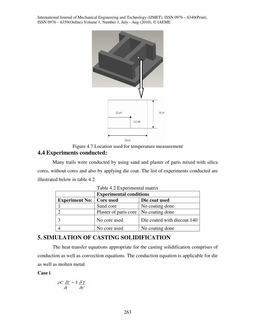
at the same location which is shown in Figure 4.7.
International Journal of Mechanical Engineering and Technology (IJMET), ISSN 0976 – 6340(Print),
ISSN 0976 – 6359(Online) Volume 1, Number 1, July - Aug (2010), © IAEME
263
Figure 4.7 Location used for temperature measurement
4.4 Experiments conducted:
Many trails were conducted by using sand and plaster of paris mixed with silica
cores, without cores and also by applying die coat. The list of experiments conducted are
illustrated below in table 4.2
Table 4.2 Experimental matrix
5. SIMULATION OF CASTING SOLIDIFICATION
The heat transfer equations appropriate for the casting solidification comprises of
conduction as well as convection equations. The conduction equation is applicable for die
as well as molten metal.
Case i
Experimental conditions
Experiment No: Core used Die coat used
1 Sand core No coating done
2 Plaster of paris core No coating done
3 No core used Die coated with diecoat 140
4 No core used No coating done

International Journal of Mechanical Engineering and Technology (IJMET), ISSN 0976 – 6340(Print),
ISSN 0976 – 6359(Online) Volume 1, Number 1, July - Aug (2010), © IAEME
264
Consider the case of die individually. The total heat flow is given by the equation.
Where ρ is the density of the die material, C is the specific heat and k is the thermal
conductivity.
Case ii
Consider the case of molten metal. Since the mode of heat transfer between the
die and the metal is conduction, the above equation proves to be ideal. Thus the heat flow
is given by the equation
Where ρ is the density of the metal, C is the specific heat and k is the conductivity
of the metal used.Here we consider the case of convection between the solidifying metal
and atmosphere. Thus the convection equation is taken into consideration. The heat flux J
generated which is the total heat per unit area is given by the equation
)( αTTmhJ −=
Where J is the flux generated, h is the interfacial heat transfer coefficient, Tm is
the temperature of the metal and Tα is the ambient temperature. For solving these
nonlinear equations, the initial and boundary conditions of the corresponding materials
are to be given as input parameters. The values of density, specific heat thermal
conductivity etc of die and metal are to be given appropriately. The most important
parameter that governs the heat transfer at the metal mold interface is the h value that is
the heat transfer coefficient value. The HTC value we obtained from experiment is to be
given as an input parameter for the simulation. For the solution of heat transfer equations,
material properties of the corresponding metal and die material are to be given as input
values. The properties of materials are shown below in table.
Material Density
Kg/m3
Conductivity
W/mK
Specific
heat
J/KgK
Convection
W/m2K
Sand 1800 1.5 1117 ---
Aluminium 2700 238 917 ---
Steel 7870 78.2 456 ---
Air 1.127 .0271 1.005 500-16500

International Journal of Mechanical Engineering and Technology (IJMET), ISSN 0976 – 6340(Print),
ISSN 0976 – 6359(Online) Volume 1, Number 1, July - Aug (2010), © IAEME
265
Simulation of casting solidification requires solving of heat transfer equations and
for that a set of initial and boundary conditions are to be given as input parameters. Here
the initial conditions are the temperatures of various materials. They are:
• Temperature of aluminium casting is 7000C
• Temperature of die is 800C
• Temperature of sand core is 300C
In addition to the initial conditions given, boundary conditions are also to be
given for solving the heat transfer equations. The boundary conditions are the convection
coefficient values of various materials. They are given by:
• Convection coefficient value between aluminium and air is 50W/m2K.
• Convection coefficient value between sand and air is 4 W/m2K.
• Convection coefficient value for die is 10W/m2K.
Convection value for air (interfacial heat transfer coefficient) is 5347W/m2K
Schematic diagram showing various boundaries
5.1 Solution methodology
Simulation of solidification can be of great benefit in improving the efficiency of
gravity die casting process. Modeling requires an accurate calculation of the changing
temperature field in casting and correct data regarding interfacial heat transfer
coefficients between die and casting. This requires good data on the thermo physical
properties of materials involved and good knowledge of initial conditions (initial
temperature field) and boundary conditions (often described by a heat-transfer
coefficient).

International Journal of Mechanical Engineering and Technology (IJMET), ISSN 0976 – 6340(Print),
ISSN 0976 – 6359(Online) Volume 1, Number 1, July - Aug (2010), © IAEME
266
5.2 Creation of model:
Simulation procedure for the experiments conducted is as follows. All the
volumes i.e., die; casting and core were created according to the arrangement in the
experimental setup as shown
Meshed model
After specifying all the initial and boundary condition by solving the model for
specified time interval, we can analyze the temperature distribution in the die-casting
model. For developing the model and to run the simulation ANSYS Parametric Design
Langue (APDL) code is used. Comparing the experimental and simulated results is one of
the most important processes in this work. For the comparison, we are conducting a chi-
squared test (χ2
test).
6. RESULTS AND DISCUSSIONS
The results obtained by conducting experiments are explained below.
6.1 Estimated heat transfer coefficient values:
The estimated values of heat transfer coefficient are reported below.
6.1.1 Case i. Without using any core or coating.
In this case, the resistance to heat transfer is offered due to air resistance alone.
Rz(die) = 7.42 µm

International Journal of Mechanical Engineering and Technology (IJMET), ISSN 0976 – 6340(Print),
ISSN 0976 – 6359(Online) Volume 1, Number 1, July - Aug (2010), © IAEME
267
Rz(cast) = 9.5 µm
Rshrinkage = 8.73 µm
Using equation (3.6)
Rz(Σ) = 20.78 µm
ka = 0.068355 W/mK
Using equation (3.7)
resista = 1.52X10⁻⁴
m2K/W
h = (1.52x10⁻⁴
)-1
= 6578 W/m
2K
6.1.2 Case ii. Using sand core
By considering equations 3.6 and 3.7,
Rz(die) = 7.42 µm
Rz(cast) = 11.35 µm
Rshrinkage = 12 µm
Rz(Σ) = 25.56 µm
ka = 0.068355 W/mK
resista = 1.84X10⁻⁴
m2K/W
h = (1.84x10⁻⁴
)-1
= 5347 W/m
2K
6.1.3 Case iii,Using dycote 140
In this case, the heat transfer is restricted due to the resistance offered by the
coating applied on the die inner surface. Here the air resistance is taken as zero.
Xmax = 31.67 µm
Ry(coat) = 17.566 µm.
Kc = .68 W/mK.
Using equation (3.3)
resistcoat = 2.8x10⁻⁴
m2K/W
Using equation (4.2)
h = (1.84x10⁻⁴
)-1
= 3571 W/m
2K

International Journal of Mechanical Engineering and Technology (IJMET), ISSN 0976 – 6340(Print),
ISSN 0976 – 6359(Online) Volume 1, Number 1, July - Aug (2010), © IAEME
268
6.7.1.4 Case iv, Using plaster core
In the case of plaster core experiment, the air resistance alone is taken into
consideration and coating resistance is considered as zero since no coating was applied.
Rz(die) = 7.42 µm
Rz(cast) = 12.5 µm
Rshrinkage = 13.53 µm
Using equation (3.6)
Rz(Σ) = 28.07 µm
ka = 0.068355 W/mK
Using equation (3.7)
resista = 2.05X10⁻⁴
m2K/W
h = (2.05x10⁻⁴
)-1
= 4870 W/m
2K
Experimental conditions
Core used Die coat used HTC values (W/m2K)
No core used No coating done 6578
Sand core No coating done 5347
No core used Die coated with diecoat 140 3571
Plaster of paris core No coating done 4870
Table 6.1 Estimated HTC values.
6.2 Cooling curves
For each of the experiments conducted, their corresponding cooling curves were
plotted by measuring temperatures at a particular location (ref Figure 4.7) at regular
intervals using a thermocouple. The curves are shown in figure 5.1.
6.2.1 Experimentally obtained cooling curves.
Figure 6.1 Cooling curves for different experimental conditions

International Journal of Mechanical Engineering and Technology (IJMET), ISSN 0976 – 6340(Print),
ISSN 0976 – 6359(Online) Volume 1, Number 1, July - Aug (2010), © IAEME
269
6.2.2 Simulation cooling curves
Finite element analysis was done for each of the four experimental conditions.
The experimentally calculated HTC values were given as input parameter for the analysis
and corresponding cooling curves were extracted. The simulation cooling curves are
shown below in figure 5.2
Figure 5.2 Simulation cooling curves
6.3 Comparison of results
The cooling curves obtained experimentally and through simulation are compared
are reported below.
6.3.1 Case i. Without using core or coating
Figure 6.3 Comparison of results obtained when no core or coating was used
International Journal of Mechanical Engineering and Technology (IJMET), ISSN 0976 – 6340(Print),
ISSN 0976 – 6359(Online) Volume 1, Number 1, July - Aug (2010), © IAEME
270
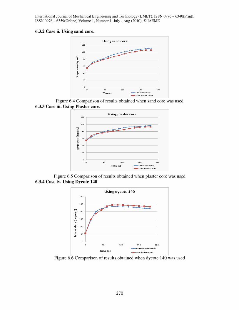
6.3.2 Case ii. Using sand core.
Figure 6.4 Comparison of results obtained when sand core was used
6.3.3 Case iii. Using Plaster core.
Figure 6.5 Comparison of results obtained when plaster core was used
6.3.4 Case iv. Using Dycote 140
Figure 6.6 Comparison of results obtained when dycote 140 was used

International Journal of Mechanical Engineering and Technology (IJMET), ISSN 0976 – 6340(Print),
ISSN 0976 – 6359(Online) Volume 1, Number 1, July - Aug (2010), © IAEME
271
For the comparison of results, chi square analysis was performed between each of
the four sets of values and finally the agreement between the each sets of values were
proved to be matching at 95% confidence interval.
The small mismatch between the results may be because of the following reasons:
• The surface roughness value of the casting was selected from the design data
available, since for as cast components the surface roughness cannot be measured.
• The solidification shrinkage has to be exactly measured and has to be incorporated in
simulation results and also the thermal expansion of the die was not taken into
consideration.
• Installation error may happen while mounting the thermocouple.
• The properties of coating material and also for plaster of paris were chosen arbitrarily.
These variations in the results can be eliminated by
• Finding the exact surface roughness values of castings produced.
• By considering the solidification shrinkage gap exactly and the thermal expansion of
the die.
• By collecting temperature histories at different locations in the experiment and this
data is to be used to calculate the HTC value theoretically.
• The properties of the chosen materials are to be considered accurately.
• Heat transfer values can be found out by changing the initial temperatures of die and
castings, boundary conditions and applying various coatings on die surface.
7. CONCLUSIONS
Heat transfer analysis were conducted on the solidification of a commercial
casting of Al alloy in a gravity die casting process. The interfacial heat transfer
coefficients were estimated using a direct method, i.e. by finding the best match between
the experimental and simulated temperature profiles in the casting. A reasonably good
agreement has been observed between experiment and modeling, thus resulting in the
generation of the value of the interfacial heat transfer coefficient. The benefits of such an
approach have been discussed. The procedure utilized to determine the interfacial heat
transfer coefficient can be applied to other casting processes.
The experimental data and subsequent calculations showed that the interfacial
heat transfer coefficient value is highest for the experiment conducted without core or

International Journal of Mechanical Engineering and Technology (IJMET), ISSN 0976 – 6340(Print),
ISSN 0976 – 6359(Online) Volume 1, Number 1, July - Aug (2010), © IAEME
272
coating and the lowest value is for experiment with dycote 140. The HTC value again
reduced when the coating thickness was increased. The influences of air gap, die coatings
and contact area of die and casting on the interfacial heat-transfer coefficient was studied.
As the air gap is increasing, interfacial heat transfer coefficient is decreasing and as the
roughness of die surface is increasing air gap is increasing there by the heat transfer
coefficient values are decreasing.
Finite element model is proposed for the analysis of permanent mold castings.
Since the experimental and simulation cooling curves are matching for the given HTC
values, these short range of (3500- 7000 W/m2K) values can be applied for simulation of
die-casting.
FUTURE WORKS
• There is scope for reducing the error between the simulated results and experimental
results by applying exact material properties, environmental conditions and finding
ways to reduce installation errors.
• Additional experimental programs for determining interfacial heat transfer coefficients
in permanent mold casting processes for a variety of geometries and alloys should be
pursued.
• Experiments can be conducted by considering solidification shrinkage and thermal
expansion of die for measuring the air gap.
• Experiments can be conducted by incorporating more number of thermocouples at
various locations.
• Heat transfer values can be found out by changing the initial temperatures of die and
castings, boundary conditions and applying various coatings on die surface.
• The time-dependent interfacial heat transfer coefficient is the result of many factors,
that greatly complicates the resolution of the problem. Using the temperature
measurement techniques described in the present program, and awaiting advances in
computer techniques for defining three-dimensional analysis techniques, the
determination of the thermal and mechanical behavior of a casting in a permanent
mold can be resolved. A further study of the time response of direct contact
thermocouples is suggested.
• Continued support of research in this area is encouraged.
International Journal of Mechanical Engineering and Technology (IJMET), ISSN 0976 – 6340(Print),
ISSN 0976 – 6359(Online) Volume 1, Number 1, July - Aug (2010), © IAEME
273
ACKNOWLEDGEMENT
We are deeply indebted to Dr R Sellamuthu, Professor, department of mechanical
engineering, Amrita University who has been kind enough to suggest this topic, for his
motivation and guidance throughout the duration of the project, by way of valuable
suggestions and ideas. We are thankful to our staff members of the Department of
Mechanical Engineering without whose help this dissertation would not have been
completed successfully. Last but not the least, I wish to express my heartfelt thanks to
God, my beloved parents and my dear friends whom always give the way success.
REFERENCES
1. Robert D. Pehlke and John T. Berry, “Investigation of Heat Transfer at the Mold/Metal
Interface in Permanent Mold Casting of Light Alloys”, Dept. of Materials Science and
Engineering ,The University of Michigan, October, 2005.
2. M.M Pariona, A.C.Mossi., “Numarical Simulation of Heat Transfer During the
Solidification of Pure Iron in Sand and Mullite molds”, Journal of the Braz.Soc. of
Mech.Sci&Eng, Vol XXVll, No.4. pp 399-406, October 2005.
3. C.P. Hallam and W.D. Griffiths., “A Model of the Interfacial Heat- Transfer coefficient
for the Aluminum Gravity Die-Casting Process”, Metallurgical and Materials
Transactions B, vol 35B, pp. 1-15. April 2004
4. R.W. Lewis and R.S. Ransing., “A Correlation to Describe Interfacial Heat transfer
during Solidification Simulation ans its Use in the Optimal feeding Design of
Castungs”, Metallurgical and Materials Transactions B,Vol 29B, pp.437-452. April
1998
5. W.D Griffiths., “A Model of the Interfacial Heat Transfer Coefficient during
Unidirectional Solidification of an Aluminum Alloy”. Metallurgical and Materials
Transactions B, Vol 31B, pp.285-295, April 2000.
6. Dr.S.Shamasundar, V.Gopalakrishna, Manjunatha, Badrinath, “Gravity Die Casting
Process: Die Design and Process Optimization”. ProSIM- AFTC, 326, III Stage IV
Block, Basaveshwara Nagar, April 2000.
7. Calcom SA, Parc Scientifique EPFL, CH-1015 Lausanne, Swaziland.
8. Prof. Karl B. Rundman., “Metal Casting (Reference Book for MY4130),” Dept. of
Materials Science and Engineering, Michigan Tech. University

International Journal of Mechanical Engineering and Technology (IJMET), ISSN 0976 – 6340(Print),
ISSN 0976 – 6359(Online) Volume 1, Number 1, July - Aug (2010), © IAEME
274
9. John, Campbell, “Castings Practice: The 10 Rules of Casting”, Elsevier. Materials and
Design, Vol 29, pp. 635–636, 2005.
10. M. Trovant and S. Argyropoulos: Metallurgical and Materials Transactions B, April
2000, vol. 31B, pp. 75-86.
11. M. Trovant and S.Argyropoulos: Metallurgical and Materials Transactions B, April
2000, vol. 31B, pp. 87-96.
EXPERIMENTAL PHOTOGRAPHS