19 mathematical modelling
TRANSCRIPT
ISSN(Online) : 2278 - 8875 ISSN (Print) : 2320 - 3765
International Journal of Advanced Research in Electrical, Electronics and Instrumentation Engineering
Vol. 2, Issue 1, January 2013
Copyright to IJAREEIE www.ijareeie.com 689
Mathematical Modelling of PMSM Vector
Control System Based on SVPWM with PI
Controller Using MATLAB Kiran Boby1, Prof.Acy M Kottalil2, N.P.Ananthamoorthy3
Assistant professor, Dept of EEE, M.A College of Engineering, Kothamangalam, India1
Professor, Dept of EEE, M.A College of Engineering, Kothamangalam, India2
Associate professor, Dept of EEE, Hindusthan College of Engineering and Technology, Coimbatore, India3
Abstract: The mathematical model of PMSM, using the powerful simulation modelling capabilities of
Matlab/Simulink is implemented. The entire PMSM control system is divided into several independent functional
modules such as PMSM body module, inverter module and coordinate transformation module and SVPWM
production module and so on. The simulation model of the PMSM control system can be obtained by combining
these modules. The main advantage of SIMULINK over other programming softwares is that, instead of
compilation of program code, the simulation model is built up systematically by means of basic function blocks.
With the simulation of the motor, we can analyse a variety of simulation waveforms and it provide an effective
means for the analysis and design of the PMSM control system.
Keywords: PMSM, SVPWM, Vector control
I. INTRODUCTION
With the development of permanent magnetic materials and control technology, permanent magnet synchronous
motor (PMSM) is mostly used due to high torque/inertia ratio, high power density, high efficiency, reliability and
ease for maintenance, and is used in CNC machine tools, industrial robots and so on. The establishment of the
simulation model of PMSM and its control system is of great significance to the verification of a variety of control
algorithms and the optimization of entire control system. To achieve high performance, the vector control of the
PMSM drive is employed.
The analysis of mathematical model of PMSM, with the powerful simulation modelling
capabilities of Matlab/Simulink, the PMSM control system will be divided into several independent functional
modules such as PMSM motor module, inverter module and coordinate transformation module and SVPWM
production module and so on. By combining these modules, the simulation model of PMSM control system can be
built.
The main advantage of SIMULINK over other programming softwares is that, instead of
compilation of program code, the simulation model is built up systematically by means of basic function blocks.
Through the simulation of the motor, we can analyse a variety of simulation waveforms and it provide an effective
means for the analysis and design of the PMSM control system.
II. PERMANENT MAGNET SYNCHRONOUS MOTOR
A permanent magnet synchronous motor (PMSM) is a motor that uses permanent magnets to
produce the air gap magnetic field rather than using electromagnets. These motors have significant advantages,
attracting the interest of researchers and industry for use in many applications.

ISSN(Online) : 2278 - 8875 ISSN (Print) : 2320 - 3765
International Journal of Advanced Research in Electrical, Electronics and Instrumentation Engineering
Vol. 2, Issue 1, January 2013
Copyright to IJAREEIE www.ijareeie.com 690
A.THE MATHEMATICAL MODEL OF PMSM
Detailed modelling of PM motor drive system is required for proper simulation of the system.
The d-q model has been developed on rotor reference frame as shown in figure 1. At any time t, the rotating rotor
d-axis makes an angle θr with the fixed stator phase axis and rotating stator mmf makes an angle α with the rotor
d-axis. Stator mmf rotates at the same speed as that of the rotor.
Fig 1. Motor Axis
The model of PMSM without damper winding has been developed on rotor reference frame using the following
assumptions:
1) Saturation is neglected.
2) The induced EMF is sinusoidal.
3) Eddy currents and hysteresis losses are negligible.
4) There are no field current dynamic
III. VECTOR CONTROL
Vector control is the most popular control technique of AC induction motors. In special
reference frames, the expression for the electromagnetic torque of the smooth-air-gap machine is similar to the
expression for the torque of the separately excited DC machine. In the case of induction machines, the control is
usually performed in the reference frame (d-q) attached to the rotor flux space vector. That’s why the
implementation of vector control requires information on the modulus and the space angle (position) of the rotor
flux space vector. The stator currents of the induction machine are separated into flux- and torque-producing
components by utilizing transformation to the d-q coordinate system, whose direct axis (d) is aligned with the
rotor flux space vector. That means that the q-axis component of the rotor flux space vector is always zero:
𝜑𝑟𝑞 = 0 and 𝑑
𝑑𝑡𝜑𝑟𝑞 = 0 (1)
The main objective of the vector control of induction motors is to independently control the
torque and the flux; this is done by using a d-q rotating reference frame synchronously with the rotor flux space
vector. In ideally field-oriented control, the rotor flux linkage axis is forced to align with the d-axes. Applying the
result of both equations, namely field-oriented control, the torque equation become analogous to the DC machine,
and can be described as follows:
𝑇𝑒 =3
2
𝑝𝐿𝑚
𝐿𝑟𝜑𝑟 𝑖𝑞𝑠 (2)
A.STEPS TO PERFORM VECTOR CONTROL
ISSN(Online) : 2278 - 8875 ISSN (Print) : 2320 - 3765
International Journal of Advanced Research in Electrical, Electronics and Instrumentation Engineering
Vol. 2, Issue 1, January 2013
Copyright to IJAREEIE www.ijareeie.com 691
1. Measure the motor quantities (phase voltages and currents).
2. Transform them to the 2-phase system (α ,β) using a Clarke transformation.
3. Calculate the rotor flux space vector magnitude and position angle.
4. Transform stator currents to the d-q coordinate system using a Park transformation.
5. The stator current torque- (isq) and flux- (isd) producing components are separately controlled.
6. The output stator voltage space vector is calculated using the decoupling block.
7. An inverse Park transformation transforms the stator voltage space vector back from the d-q coordinate
system to the 2-phase system fixed with the stator.
8. Using the space vector modulation, the output 3-phase voltage is generated.
IV SPACE VECTOR PULSE WIDTH MODULATION
A. PRINCIPLE
SVPWM tries to output a sine-wave, supplying power, whose three parts are balanced and
whose frequency and voltage can be adjusted. Its controlling principle is to try to decrease output harmonic
components. Three- phase windings of the motor can define a three phase static coordinate system. It has three
axes. The phase voltage of three-phase stator Ua, Ub and Uc are on three-phase windings, and form three phase
voltage vector Ua, Ub and Uc. Their directions are on their own axis and their volumes change with time in
accordance with the sine regulation. Therefore, all three phase voltage space vector form a total voltage space
vector u, which is a space vector circulating at the speed of power angle frequency ω.
Motor can be controlled by making use of the opening and closing condition and the orders of
the inverter power and by modulating the time of opening and closing. Different combinations of switch tube
constitute eight space voltage vectors, six of which are non-zero voltage vectors and the other two are zero
vectors. After Clark transforming, phase voltage in the three-phase ABC plane coordinate system can be changed
into αβ right-angled coordinate system. Its transforming formula is:
𝑈𝛼
𝑈𝛽 =
2
3 1
0
−1
2
3
2
−1
2
− 3
2
𝑈𝑎
𝑈𝑏
𝑈𝑐
(3)
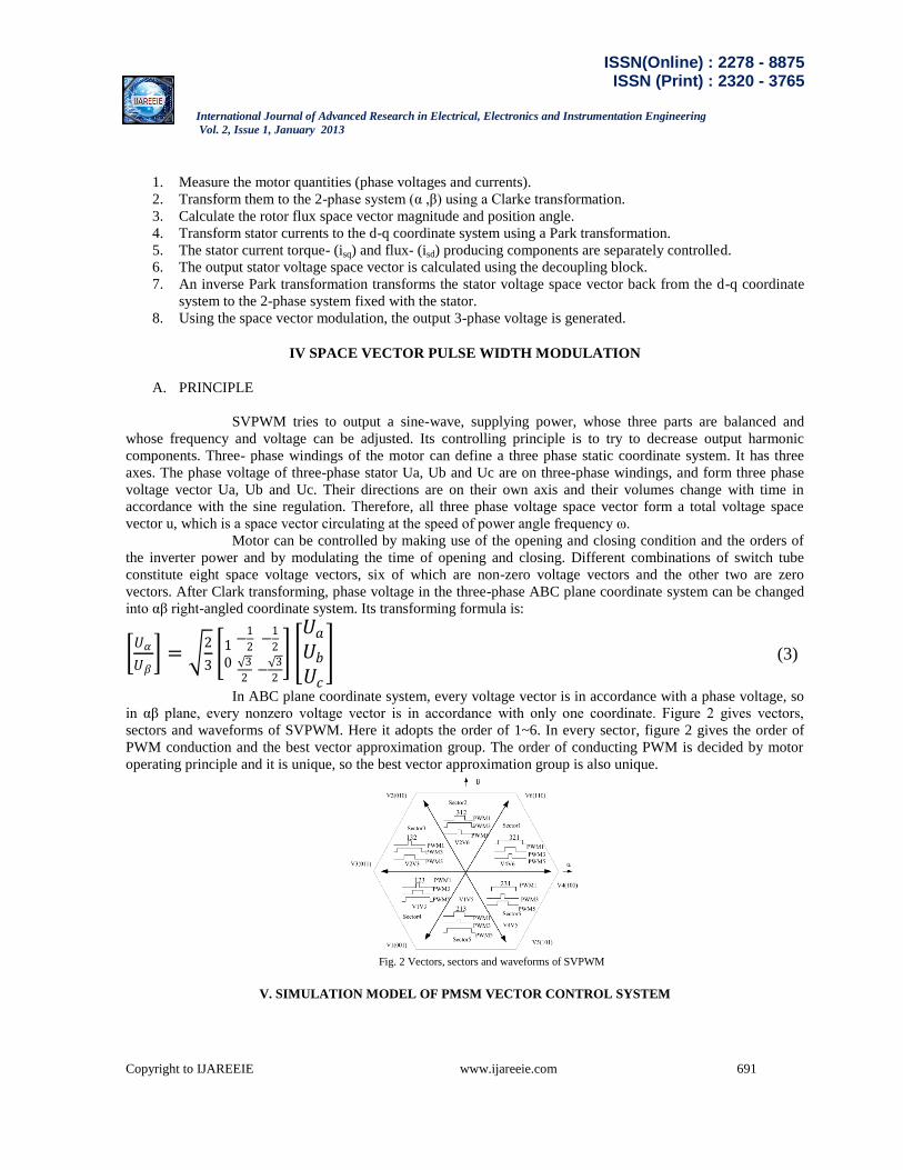
In ABC plane coordinate system, every voltage vector is in accordance with a phase voltage, so
in αβ plane, every nonzero voltage vector is in accordance with only one coordinate. Figure 2 gives vectors,
sectors and waveforms of SVPWM. Here it adopts the order of 1~6. In every sector, figure 2 gives the order of
PWM conduction and the best vector approximation group. The order of conducting PWM is decided by motor
operating principle and it is unique, so the best vector approximation group is also unique.
Fig. 2 Vectors, sectors and waveforms of SVPWM
V. SIMULATION MODEL OF PMSM VECTOR CONTROL SYSTEM

ISSN(Online) : 2278 - 8875 ISSN (Print) : 2320 - 3765
International Journal of Advanced Research in Electrical, Electronics and Instrumentation Engineering
Vol. 2, Issue 1, January 2013
Copyright to IJAREEIE www.ijareeie.com 692
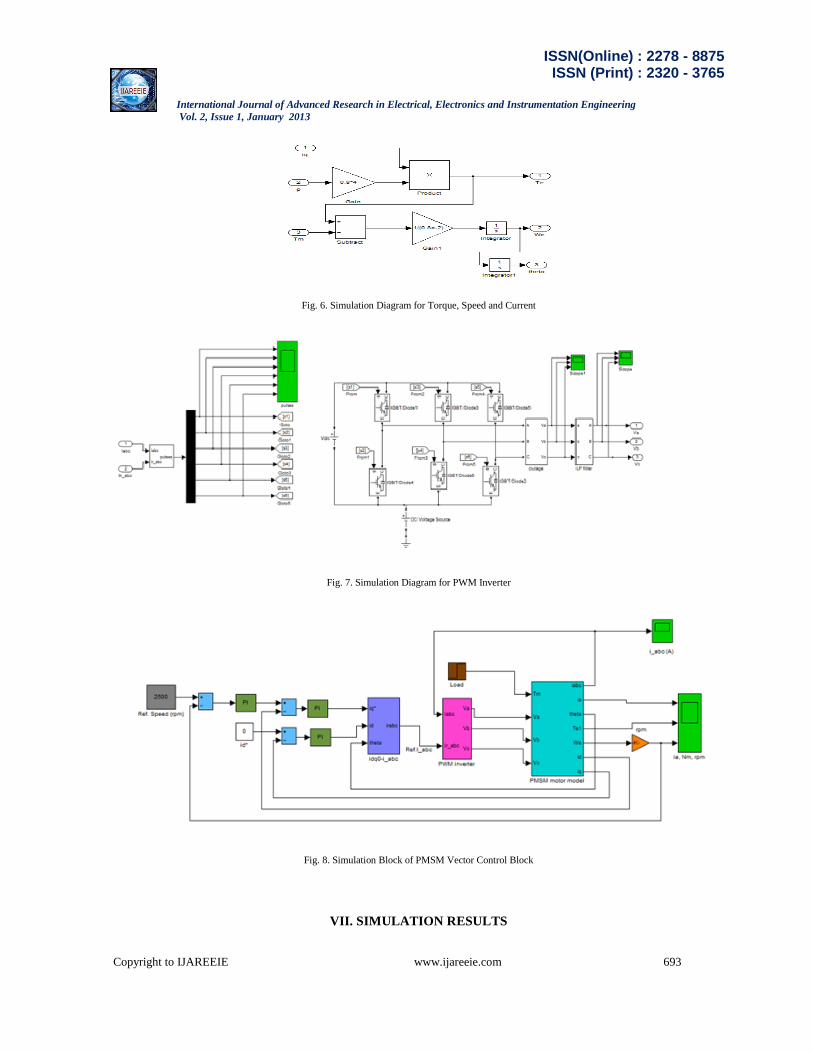
The PMSM control system mainly includes: PMSM body module, inverter module, coordinate transformation
module and SVPWM production module.
Fig. 3. Simulation Diagram for D-Axis Current
Fig. 4. Simulation Diagram for Q-Axis Current
Fig. 5. Simulation Diagram for D-Q Axis Current (Idq)
ISSN(Online) : 2278 - 8875 ISSN (Print) : 2320 - 3765
International Journal of Advanced Research in Electrical, Electronics and Instrumentation Engineering
Vol. 2, Issue 1, January 2013
Copyright to IJAREEIE www.ijareeie.com 693
Fig. 6. Simulation Diagram for Torque, Speed and Current
Fig. 7. Simulation Diagram for PWM Inverter
Fig. 8. Simulation Block of PMSM Vector Control Block
VII. SIMULATION RESULTS

ISSN(Online) : 2278 - 8875 ISSN (Print) : 2320 - 3765
International Journal of Advanced Research in Electrical, Electronics and Instrumentation Engineering
Vol. 2, Issue 1, January 2013
Copyright to IJAREEIE www.ijareeie.com 694
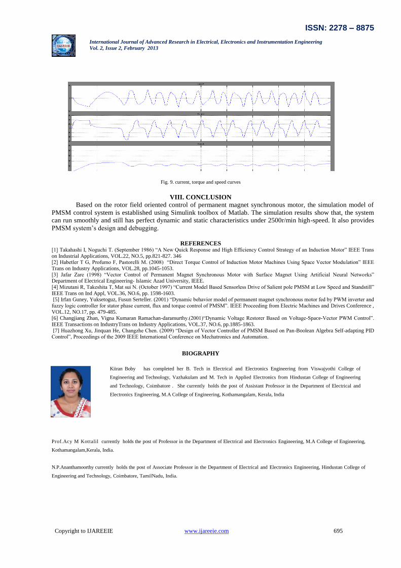
In this paper, PI controller for PMSM is used and the following results are obtained;
The simulation model of PMSM control system is established using Simulink toolbox of Matlab.
The parameters of PMSM are as follows: p = 4, 𝐿𝑑= 𝐿𝑞 = 0.0085H, 𝑅𝑠= 2.875Ω, J= 0.0008 kg𝑚2,
IGBT’s switching frequency is 10KHz. The given speed is 2500r/min, no-load start; we can get the three-
phase current torque and speed curves as shown in figure 9.
ISSN: 2278 – 8875
International Journal of Advanced Research in Electrical, Electronics and Instrumentation Engineering
Vol. 2, Issue 2, February 2013
Copyright to IJAREEIE www.ijareeie.com 695
Fig. 9. current, torque and speed curves
VIII. CONCLUSION
Based on the rotor field oriented control of permanent magnet synchronous motor, the simulation model of
PMSM control system is established using Simulink toolbox of Matlab. The simulation results show that, the system
can run smoothly and still has perfect dynamic and static characteristics under 2500r/min high-speed. It also provides
PMSM system’s design and debugging.
REFERENCES
[1] Takahashi I, Noguchi T. (September 1986) “A New Quick Response and High Efficiency Control Strategy of an Induction Motor” IEEE Trans
on Industrial Applications, VOL.22, NO.5, pp.821-827. 346
[2] Habetler T G, Profumo F, Pastorelli M. (2008) “Direct Torque Control of Induction Motor Machines Using Space Vector Modu lation” IEEE
Trans on Industry Applications, VOL.28, pp.1045-1053.
[3] Jafar Zare (1998) “Vector Control of Permanent Magnet Synchronous Motor with Surface Magnet Using Artificial Neural Networks” Department of Electrical Engineering- Islamic Azad University, IEEE.
[4] Mizutani R, Takeshita T, Mat sui N. (October 1997) “Current Model Based Sensorless Drive of Salient pole PMSM at Low Speed and Standstill”
IEEE Trans on Ind Appl, VOL.36, NO.6, pp. 1598-1603. [5] Irfan Guney, Yuksetoguz, Fusun Serteller. (2001) “Dynamic behavior model of permanent magnet synchronous motor fed by PWM inverter and
fuzzy logic controller for stator phase current, flux and torque control of PMSM”. IEEE Proceeding from Electric Machines and Drives Conference ,
VOL.12, NO.17, pp. 479-485. [6] Changjiang Zhan, Vigna Kumaran Ramachan-daramurthy.(2001)“Dynamic Voltage Restorer Based on Voltage-Space-Vector PWM Control”.
IEEE Transactions on IndustryTrans on Industry Applications, VOL.37, NO.6, pp.1885-1863.
[7] Huazhong Xu, Jinquan He, Changzhe Chen. (2009) “Design of Vector Controller of PMSM Based on Pan-Boolean Algebra Self-adapting PID Control”, Proceedings of the 2009 IEEE International Conference on Mechatronics and Automation.
BIOGRAPHY
Kiiran Boby
has completed her B. Tech in Electrical and Electronics Engineering from Viswajyothi College of
Engineering and Technology, Vazhakulam and M. Tech in Applied Electronics from Hindustan College of Engineering
and Technology, Coimbatore . She currently holds the post of Assistant Professor in the Department of Electrical and
Electronics Engineering, M.A College of Engineering, Kothamangalam, Kerala, India
Prof.Acy M Kottalil
currently holds the post of Professor in the Department of Electrical and Electronics Engineering, M.A College of Engineering,
Kothamangalam,Kerala, India.
N.P.Ananthamoorthy currently holds the post of Associate Professor in the Department of Electrical and Electronics Engineering, Hindustan College of
Engineering and Technology, Coimbatore, TamilNadu, India.