1867 confederation log & timber frame€¦ · - 3 - 1867 confederation log & timber frame...
TRANSCRIPT

- 1 -
1867 CONFEDERATION LOG &
TIMBER FRAME CONSTRUCTION MANUAL
“Let’s Get It Together”

- 2 -
1991, Century Old Wood Products 1981 Inc. (Revised 01/2010)
All rights reserved. No part of this publication may be reproduced in any form or by any means, electronic, mechanical photocopying recording or otherwise without the prior permission of this copyright owner.
- 3 -
1867 CONFEDERATION LOG & TIMBER FRAME
CONSTRUCTION MANUAL
This construction manual was designed to be used in conjunction with your set of blueprints and detail sheets to assist you in building your 1867 Confederation Log & Timber Frame. You and your builder should review this manual, and your blueprints and detail sheets, before commencing construction. Any discrepancies found on your blueprints should be reported to your representative immediately. Should details on your blueprints differ from those in this manual, the blueprints shall take precedence.
Most methods of construction encountered when building an 1867 Confederation Log & Timber Frame have been illustrated in this manual. Every possible situation cannot be shown, so care should be taken when following these details since your application may vary in some way.
The Ontario Building Code Act (0. Reg. 403/97) has been followed in the drawing of your blueprints and the making of this manual. Local codes and building inspectors should be consulted for specifics not mentioned on your blueprints, and to verify those that are, meet local requirements. 1867 Confederation Log & Timber Frame must be notified of any changes required, prior to ordering your home.
- 4 -
TABLE OF CONTENTS Page # Fig. 1 Batterboards 7 Fig. 2 Squareness of Layout 7 Fig. 3 Determine a Right Angle 7 Fig. 4 Footing Forms 8 Fig. 5 Standard Foundation 8 Fig. 6 Slab Foundation 9 Fig. 7 Pressure Treated Foundation 9 Fig. 8 Support Column Footing 10 Fig. 9 Stepped Footings 10 Fig. 10 Window Wells 11 Fig. 11 Deck & Porch Piers 11 Fig. 12 Block Laying 11 Fig. 13 Pilasters 12 Fig. 14 Built-up Wood Beams 12 Fig. 15 Beam Pockets 13 Fig. 16 Pier Foundation 14 Fig. 17 Floor Openings 15 Fig. 18 Cantilevered Floor Joists 15 Fig. 19 Blocking Under Partitions 16 Fig. 20 Floor Beams & Joists 17 Crawl Space Piers 17 Fig. 21 Subfloor 18 Fig. 22 TJI Floor 18 Fig. 24 Log on Subfloor 19 Fig. 25 Log Profiles 20 Fig. 26 Lapped Corner 20 Fig. 27 Starting Your Logs 21 Fig. 28 Log Anchoring 21 Fig. 29 Placement of Logs 22 Fig. 30 Sealing the Dovetail 22 Expanding Foam Hole 23 Fig. 31 Nailing Log Corners 24 Fig. 32 Countersinking Spikes 24 Fig. 33 Thru-Bolts 25 Fig. 34 Insulating Router Hole 25 Fig. 35 Butt Joining Two Logs 26 Butt Joining Two Porch Beams 26 Fig. 36 Butting a Log Wall to Another 27 Fig. 37 Angled Corners 28 Fig. 38 Dowels 28 Fig. 39 Electrical Outlets 29 Fig. 40 Switches & Outside Lights 29 Fig. 41 a. Log-to-Roof Airseal (Truss) 31
b. Log-to-Floor Airseal (2x6 T&G) 31 c. Log-to-Floor Airseal (Conven.) 31 d. Log-to-Roof Airseal (Rafter) 31 e. Window & Door Airseal 31
(Framed Wall) f. Ridge Beam Airseal 31 g. Partition Airseal 32
Page #
h. Closet Ceiling Airseal 32 i. Main Floor to Foundation Airseal 32 j. B/U Beam 32 k. Main Floor to Pad Found. Airseal 32 l. Conventional Frame 32 m. Basement Seal (Subfloor Seal) 33 n. Ceiling Seal Upper Floor 33 o. Log-to-Gable End Airseal 33
Fig. 42 Trusses 34 Fig. 43 Fireplace – Opening in Roof 35 Skylights 35 Fig. 44 2x12 Log Siding Corners 36 Fig. 45 Floor Joist Set Back for 2x12 36 Fig. 46 Decorative Dovetails 37 Fig. 47 Open-to-Below with 2x12 int./ext. 38 Open-to-Below with 2x12 interior 1x8 exterior 38 Open-to-Below with 2x12 exterior 38 Fig. 48 Second Floor on Framed Main Floor Walls 39 Fig. 49 Gable End – Truss with 2x12 39 Fig. 50 Truss Roof – Framed Main Floor 40 Fig. 51 Settlement Allowance at 2x12 Exterior Siding 41 Settlement Allowance at 2x12 Interior Siding 41 Fig. 52 Gable End on Truss with 1x8 42 Fig. 53 Interior Gable with Scissor Truss & 1x8 43 Interior Gable with Scissor Truss & 2x12 43 Fig. 54 Framed Gable End 44 Rake 44 Fig. 55 Roof 45 Soffit 45 Fascia 45 Insulating the Roof 45 Fig. 56 Screwjack – Interior 46 Fig. 57 6x11 & 6x12/8x12 Structural Floor Beams 46 Fig. 58 2x6 Tongue & Groove Flooring 47 Fig. 59 Open to below 47 Double Rafter at Low End 47 Fig. 60 Laminated Beams at Point Load Lintels 48 Fig. 61 Shed Dormer 49 Framed Shed Roof 50 Insulating the Walls 50 Fig. 62 False Roof 50 False Roof – Side of Shed Wall 50 Fig. 63 Gable Dormer Atop Roof 51 Main Building TJI Rafters 51 Fig. 64 Gable Dormer on Floor 52

- 5 -
Page # Kneewall 53 Main Building Rafters & Joists 53 Insulating the Floor 53 Fig. 65 Rafter Bearing-Log or Kneewall 54 Floor Jsts Hangered to Log Wall 54 Fig. 66 TJI Rafters Bearing at Ridge 55 Fig. 67 Dual Pitch TJI Rafter Support 55 Fig. 68 TJI Rafter Bearing at Low End 56 Overhang on Gable End w/ TJI’s 56 Fig. 69 Laminated Valley with TJI Rafters 57 Fig. 70 Ridge Overhangs 57 Fig. 71 TJI Rafters with Low Pitch 58 Fig. 72 Porch Roof with TJI Rafters 58 Fig. 73 Shingled Ridge Vent 59 Other Roof Vents 59 Double Rafter at Ridge 59 Fig. 74 Cedar Shake Roof 60 Steel Roof 60 Fig. 75 a. Drip Cap in Log 60 b. Drip Cap in Frame 60 c. Wall to Roof Flashing 61 d. Wall to Roof Vent 61 e. Step Flashing 61 f. Counter Flashing in Log 61 g. Counter Flashing in Frame 62 h. Valley Flashing 62 i. Chimney Counter Flashing 62 Fig. 76 Basement Partitions 62 Basement Bearing Partitions 63 Fig. 77 Stud Nailers 63 Fig. 78 Slip Joint 63 Fig. 79 Closet Ceilings 64 Fig. 80 Settlement Allowance at Joists 64 Fig. 81 Settlement Allowance at Trusses 64 Fig. 82 Door Headers 65 Fig. 83 Interior Doors 65 Fig. 84 Door Openings 66 1x4 Exterior Window/Door Trim 66 Fig. 85 Window Openings 66 Fig. 86 Screwjacks & Posts at Large
Page # Openings 67 Fig. 87 Garage Door Frame – Wood Sectional Door 68 Fig. 88 Garage Door Frame – Steel or Wood Slab Door 68 Fig. 89 Garage Door Frame at Top 69 Fig. 90 Bay Windows 69 Fig. 91 Drywall 70 Fig. 92 Cornice Trim 71 Fig. 93 Interior Corner Trim 71 Fig. 94 1x6 Tongue & Groove Flooring 72 1x6 Tongue & Groove Ceiling 72 Fig. 95 Deck – Standard 73 Deck – Cantilevered 73 Railing 73 Fig. 96 Gingerbread at Porch Post 74 Fig. 97 Screwjack at Porch Post 74 Fig. 98 Finial Post 75 Gingerbread at Gables 75 Rosettes 75 Fig. 99 Beam Truss 76 Fig. 100 Decorative Beams 77 Fig. 101 Decorative Shutters 77 Fig. 102 6x11 & 6x12 Structural Floor 78 Structural Roof Beams 78 Structural Porch Beams 78 Fig. 103 Completing the Beamed Floor And Roof 79 Fig. 104 Kitchen Cupboards 80 Fig. 105 Plumbing 80 Bathrooms at Structural Beams 80 Fig. 106 Nail Types & Uses 81 Care and Maintenance of Your Log Home 82 Maintenance Schedule and Owners Log 83 Index 84-85

- 6 -

- 7 -
Figure 1. BATTER BOARDS
This is one method of obtaining the foundation location, and retaining it during excavation . Plumb lines are dropped to pin-point the footing corners.
Figure 2. SQUARENESS OF LAYOUT To determine if the layout is square, measure diagonally from A to C, and from B to D. The
two distances should be equal.
Figure 3. DETERMINE A RIGHT ANGLE
A ratio method can be used to obtain a 90 degree angle.
- 8 -
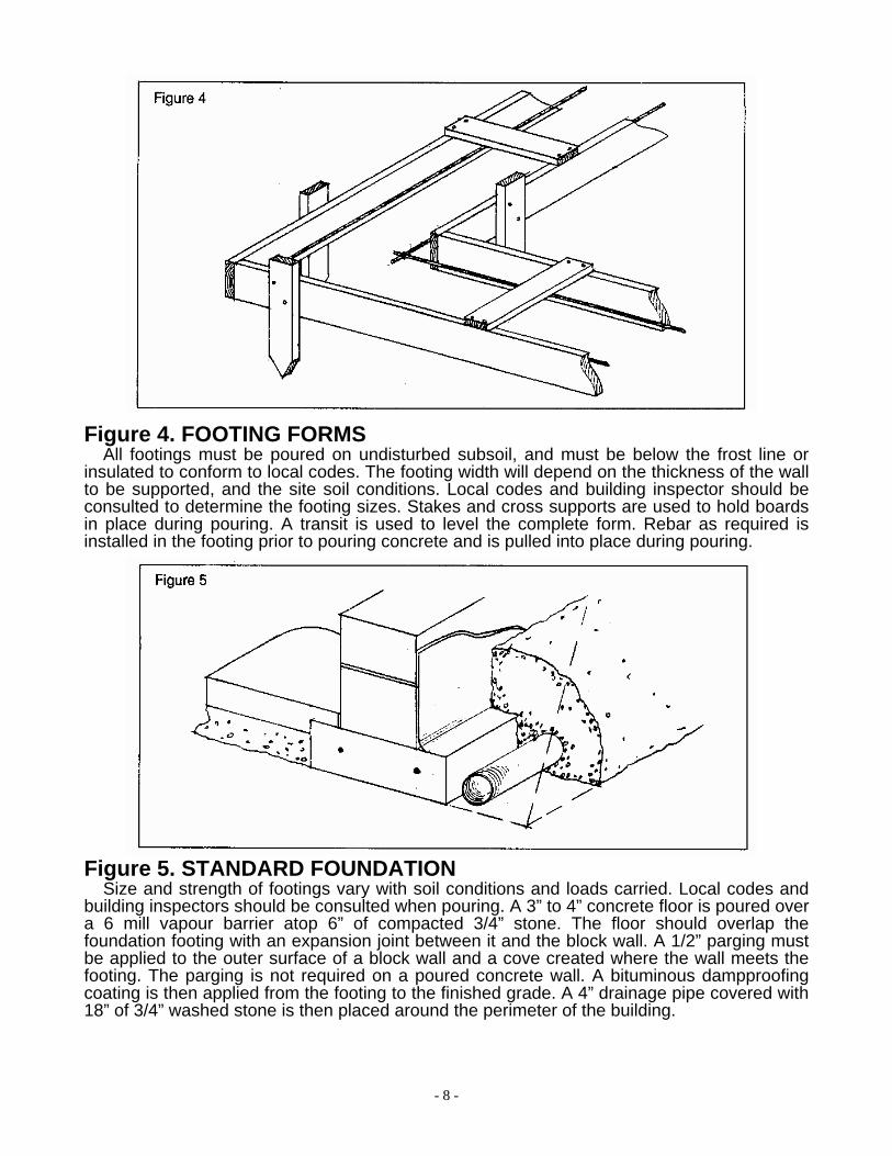
Figure 4. FOOTING FORMS All footings must be poured on undisturbed subsoil, and must be below the frost line or
insulated to conform to local codes. The footing width will depend on the thickness of the wall to be supported, and the site soil conditions. Local codes and building inspector should be consulted to determine the footing sizes. Stakes and cross supports are used to hold boards in place during pouring. A transit is used to level the complete form. Rebar as required is installed in the footing prior to pouring concrete and is pulled into place during pouring.
Figure 5. STANDARD FOUNDATION Size and strength of footings vary with soil conditions and loads carried. Local codes and
building inspectors should be consulted when pouring. A 3” to 4” concrete floor is poured over a 6 mill vapour barrier atop 6” of compacted 3/4” stone. The floor should overlap the foundation footing with an expansion joint between it and the block wall. A 1/2” parging must be applied to the outer surface of a block wall and a cove created where the wall meets the footing. The parging is not required on a poured concrete wall. A bituminous dampproofing coating is then applied from the footing to the finished grade. A 4” drainage pipe covered with 18” of 3/4” washed stone is then placed around the perimeter of the building.

- 9 -
Figure 6. SLAB FOUNDATION
Size and strength of footings vary with soil conditions and loads carried. Local codes and building inspectors should be consulted when pouring. A 6 mill vapour barrier should be placed over the 3/4” stone prior to pouring the concrete slab. A 4” drainage pipe covered with 3/4” washed stone is placed around the perimeter of the building. Rigid insulation as per local code requirements is installed around the perimeter as well. A 2x6 sill plate atop a 6” sill gasket is anchored around the perimeter of the slab. See Figure 28 for details on anchor bolts. Another 6” sill gasket is required between the plate and log wall. 4” sill gasket and 2x4 sleepers are laid on the flat spaced 4 feet o/c to support the 2x4 joists spaced 16” o/c. 5/8” tongue and groove floor plywood is nailed and glued to the 2x4 joists. A drip cap is set into caulking in an angled saw cut at the bottom of the log wall.
Figure 7. PRESSURE TREATED FOUNDATION Eight inches of 3/4” washed stone is leveled to provide a base for the 2x8 pressure treated
footing plate. The 2x6 pressure treated frame wall with studs 16” o/c, is nailed onto the footing plate. 5/8” pressure treated plywood with a waterproof membrane is used on the exterior below grade. Horizontal blocking is installed 4 feet up the wall, and 4-2x6 built-up posts are used under built-up floor beams. When the backfill exceeds 6 feet above the floor, 2x8 studs and 2x10 footing plate should be used. Local codes and building inspectors should be consulted when constructing the foundation. A 6 mil vapour barrier should be placed over the fill and a 3” to 4” concrete slab can then be poured. A 4” drainage pipe covered with 18” of 3/4” washed stone is then placed around the perimeter of the building.

- 10 -
Figure 8. SUPPORT COLUMN FOOTINGS Size and strength of footings vary with soil conditions and loads supported. Local codes
and building inspectors should be consulted when pouring.
Figure 9. STEPPED FOOTINGS The contour of the site and the style of building may call for a stepped footing. The
minimum run allowed for is 24”. The maximum rise allowed is 16”. Local codes and building inspectors should be consulted for minimum requirements based on site soil conditions.

- 11 -
Figure 10. WINDOW WELLS
If a window is below grade level a well is required. A 4” drainage pipe with 3/4” washed stone over it, is recommended to take surface water to the sump pump or away by natural drainage.
Figure 11. DECK AND PORCH PIERS Pier blocks or sono tubes are used to provide bearing for deck beams and porch posts.
The size of footing for the pier is determined based on site soil conditions.
Figure 12. BLOCK LAYING On the footing, lay out the foundation size. Measure the diagonals to insure squareness
(see Figure 2). Start at corners and lay 6 courses, keeping them level and plumb. A string line is used to assist in laying the blocks between the corners. The second-to-last course is to be semi-solid block. The top course is a 6” block for the log to sit on. Install 1/2” anchor bolts in the second-to-last course of semi-solid block so the sill plate can be anchored. Anchor bolts, sill gasket, and sill plates are required only along the walls where the joists bear, and not along the walls parallel to the joists. The log anchor bolts are to be installed in the top course of 6” block. Where a full log start is used, the log anchor bolts should extend no more than 9-1/2” out of the block. Where a half log start is used, the log anchor bolts should extend no more than 15-1/2” out of the block. Reference Figure 21 and Figure 28 for illustrations of the log anchor bolts.
NOTE: It is important to keep the foundation level, square, and plumb.

- 12 -
Figure 13. PILASTERS Where a bearing post is required alongside a foundation wall, a pilaster column is required
rather than a regular footing. This is because the footing must be poured atop the undisturbed subsoil.
Figure 14. BUILT-UP WOOD BEAMS
Blueprints will indicate the size and location of built-up beams. The material breakdown supplied with the package will indicate the lengths of the materials to be used when constructing the beam. Joints not positioned above a post should fall within 6” of the 1/4 point of the clear span. The members must be nailed together with a double row of nails, spaced no more than 16” apart in each row, with the end nails located 4” to 6” from the end of each member. The nails in each row should be staggered as shown. All lumber should be placed crown up.
- 13 -
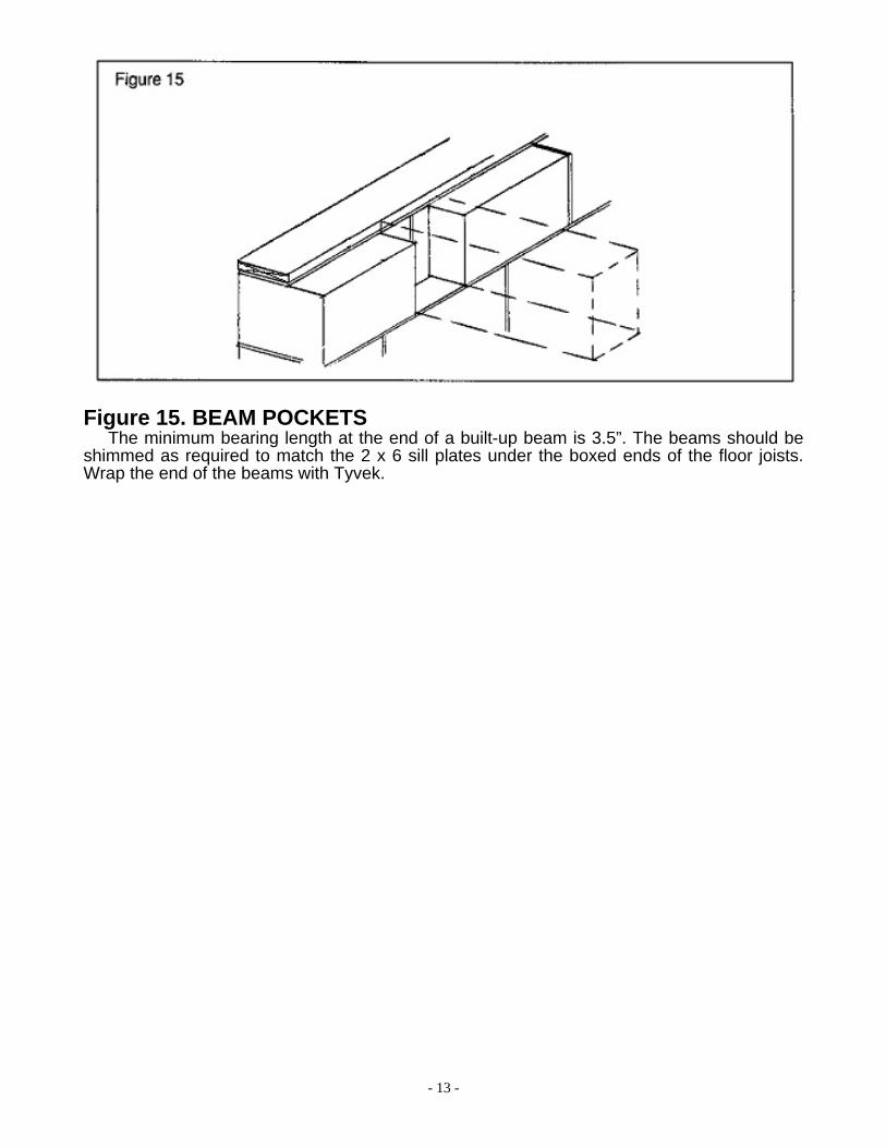
Figure 15. BEAM POCKETS The minimum bearing length at the end of a built-up beam is 3.5”. The beams should be
shimmed as required to match the 2 x 6 sill plates under the boxed ends of the floor joists. Wrap the end of the beams with Tyvek.
- 14 -
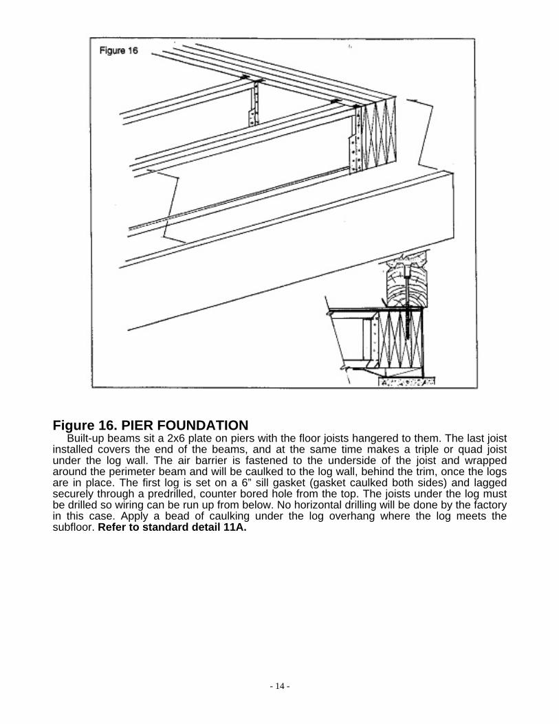
Figure 16. PIER FOUNDATION Built-up beams sit a 2x6 plate on piers with the floor joists hangered to them. The last joist
installed covers the end of the beams, and at the same time makes a triple or quad joist under the log wall. The air barrier is fastened to the underside of the joist and wrapped around the perimeter beam and will be caulked to the log wall, behind the trim, once the logs are in place. The first log is set on a 6” sill gasket (gasket caulked both sides) and lagged securely through a predrilled, counter bored hole from the top. The joists under the log must be drilled so wiring can be run up from below. No horizontal drilling will be done by the factory in this case. Apply a bead of caulking under the log overhang where the log meets the subfloor. Refer to standard detail 11A.

- 15 -
Figure 17. FLOOR OPENINGS Openings in floors for stairs, access hatches, and fireplaces are constructed in this
manner. Joist hangers must be used in accordance to manufacture specifications. Reference blueprints for location, size, and quantity of headers and trimmers.
An allowance of 2” must be made for log settlement when constructing the fireplace. Due to the variety of sizes and styles of fireplaces, the materials and flashing required can vary. A masonry contractor should be consulted for various construction methods and materials required.
Figure 18. CANTILEVERED FLOOR JOISTS Solid blocking is required over the 2x6 sill plate. The size and location of the opening and
the projection of the joists will be noted on the blueprints.
- 16 -
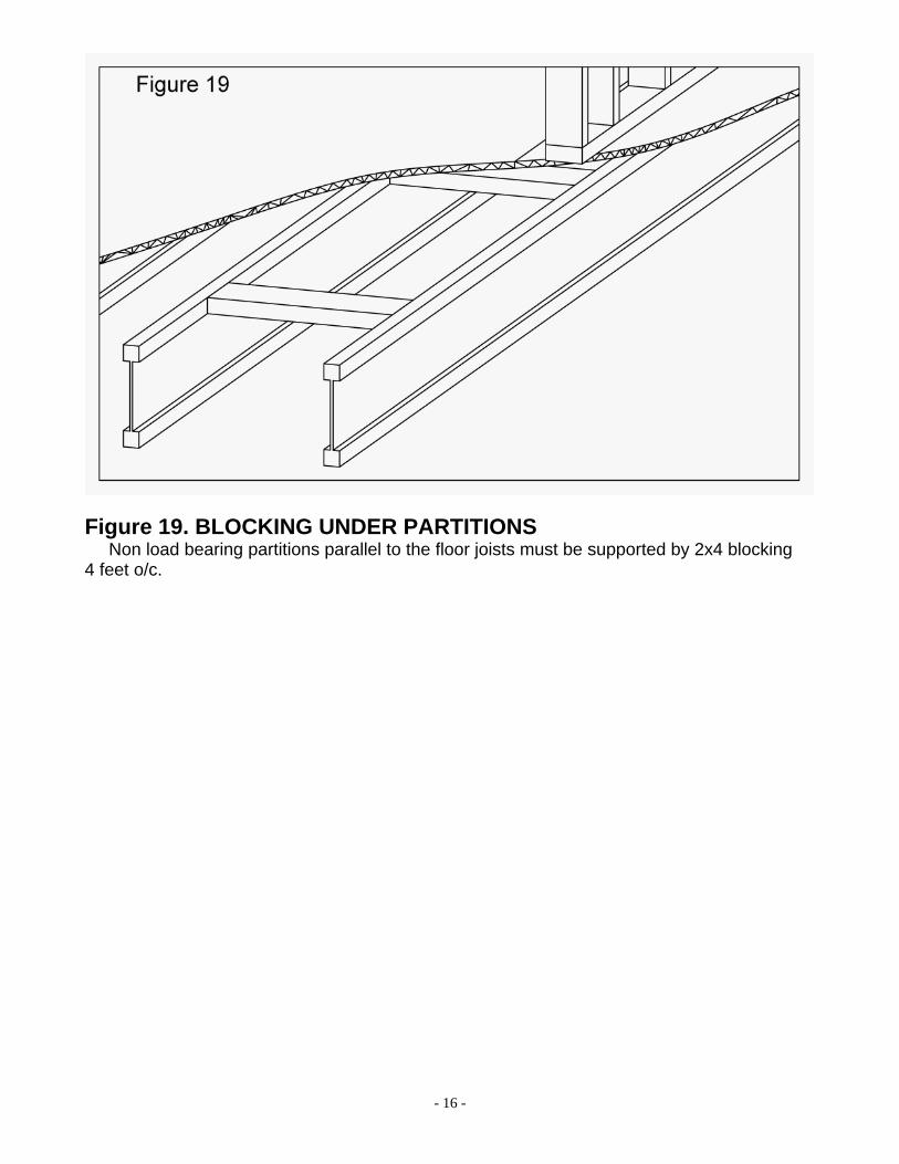
Figure 19. BLOCKING UNDER PARTITIONS Non load bearing partitions parallel to the floor joists must be supported by 2x4 blocking
4 feet o/c.

- 17 -
Figure 20. FLOOR BEAMS AND JOISTS The main floor beam is supported by 3” diameter steel teleposts. The floor joists run at
right angle to the beam. With a TJI floor, squash blocks are required between the beam and upper posts (refer to TrusJoist Framers Guide). Note the adjuster for the telepost is at the bottom where it can be hidden behind the baseboard. Atop the telepost is the second floor beam. Reference blueprints to determine if the floor joists are hangered to the beam or resting atop it. With 2x_ floor joists, placed crown side up, blocking is required between the beam and the upper telepost. Cross bridging is also added between the joists at 6’-10” o/c maximum before the 5/8” T & G plywood is glued and nailed. Note, the plywood must overhang the joists by 1” if a 6” wide log is used. The bottom of the cross bridging should not be nailed until after the subfloor is complete. 1x4 strapping at 6’-10”o/c maximum is nailed to the bottom of the floor joist where a finished ceiling is not applied.
CRAWLSPACE PIERS (not illustrated)
If a crawlspace is used under the structure, pier blocks or sono tubes, (as illustrated in Figure 11), are used instead of teleposts to provide bearing for floor beams.

- 18 -
Figure 21. SUBFLOOR 4’ x 8’ x 5/8” T & G plywood is glued and nailed to the floor joists. The joints are staggered
to create a stronger floor.
Figure 22. TJI FLOOR The 6” sill gasket and 3’-0” air barrier (around perimeter) is placed on the semi-solid
course of 10” block, and a single 2x6 sill plate anchored over it.

- 19 -
Figure 24. LOGS ON SUBFLOOR WITH WOOD FOUNDATION This occurs when a pressure treated foundation is used, or a frame wall replaces part of
a block or poured. Before the logs are placed, a 6” sill gasket with acoustical caulking on both sides, is laid on the subfloor. The logs are screwed (6” Min. screws) securely through from the bottom. Wiring is run up through the subfloor into the log therefore no horizontal drilling, at the subfloor, will be done by the factory in this case. Apply a bead of caulking under the log overhang where the log meets the subfloor.

- 20 -
Figure 25. LOG PROFILES
The v-joint profile with dovetail corners is standard. The chinked profile can be added to the exterior, interior, or both.
Figure 26. LAPPED LOCK CORNER Our lapped lock corner can be used with either the v-joint profile or the chinked profile,
instead of the dovetail corner.
- 21 -
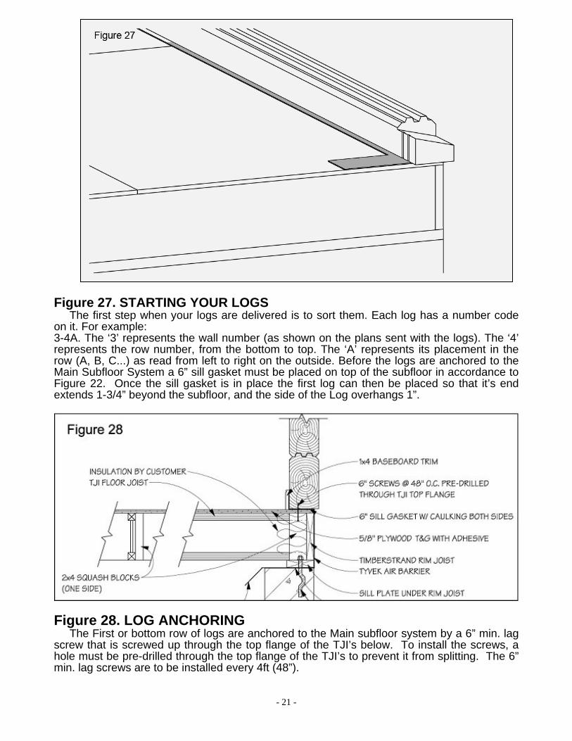
Figure 27. STARTING YOUR LOGS The first step when your logs are delivered is to sort them. Each log has a number code
on it. For example: 3-4A. The ‘3’ represents the wall number (as shown on the plans sent with the logs). The ‘4’ represents the row number, from the bottom to top. The ‘A’ represents its placement in the row (A, B, C...) as read from left to right on the outside. Before the logs are anchored to the Main Subfloor System a 6” sill gasket must be placed on top of the subfloor in accordance to Figure 22. Once the sill gasket is in place the first log can then be placed so that it’s end extends 1-3/4” beyond the subfloor, and the side of the Log overhangs 1”.
Figure 28. LOG ANCHORING The First or bottom row of logs are anchored to the Main subfloor system by a 6” min. lag screw that is screwed up through the top flange of the TJI’s below. To install the screws, a hole must be pre-drilled through the top flange of the TJI’s to prevent it from splitting. The 6” min. lag screws are to be installed every 4ft (48”).

- 22 -
Figure 29. PLACEMENT OF LOGS A row of 6” sill gasket is placed on the subfloor, and the half logs set into position. Two
rows of elastomeric caulking tape are placed on the tongues, one row of foam tape is placed in the groove. Be sure to place foam tape around the thru-bolt holes and not over them so as not to break the triple seal. The first course of logs must be square and plumb since this will affect all other logs. After the logs are erected, apply a bead of caulking under the log overhang where the log meets the foundation.
Figure 30. SEALING THE DOVETAIL Before placing the log, add acoustical caulking to the 2 vertical grooves in the dovetail. Do
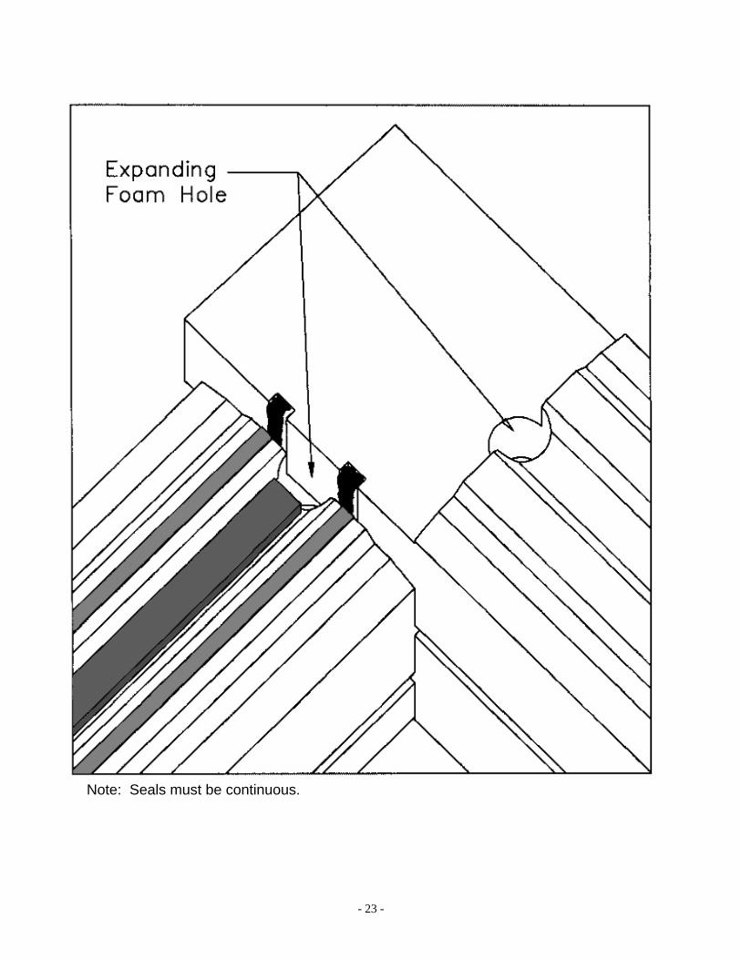
not fill the entire groove. Overfill the groove to one side only. This will provide the most effective seal, as well as ensuring that all of the caulking stays within the groove when the next log is set in place. After the dovetail is clamped and spiked, (see following details), fill the expanding foam hole careful not to over fill, a dovetail gasket can be placed atop the dovetail to the inside of the corner.
- 23 -
Note: Seals must be continuous.
- 24 -
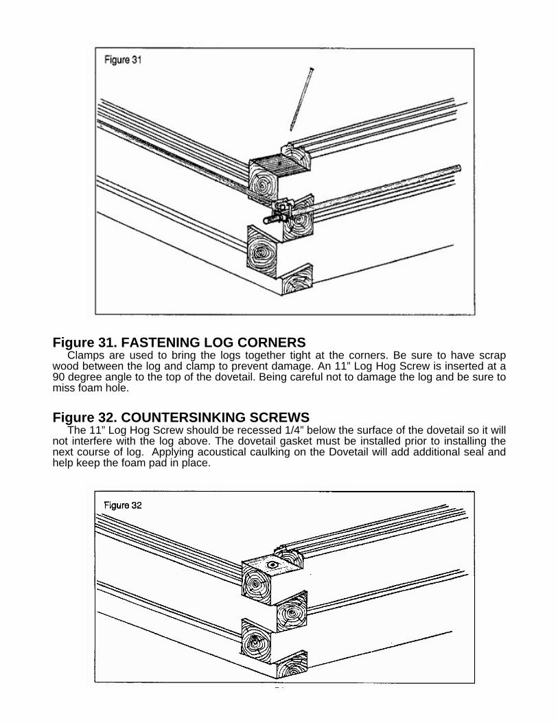
Figure 31. FASTENING LOG CORNERS
Clamps are used to bring the logs together tight at the corners. Be sure to have scrap wood between the log and clamp to prevent damage. An 11” Log Hog Screw is inserted at a 90 degree angle to the top of the dovetail. Being careful not to damage the log and be sure to miss foam hole. Figure 32. COUNTERSINKING SCREWS
The 11” Log Hog Screw should be recessed 1/4” below the surface of the dovetail so it will not interfere with the log above. The dovetail gasket must be installed prior to installing the next course of log. Applying acoustical caulking on the Dovetail will add additional seal and help keep the foam pad in place.

- 25 -
Figure 33. THRU-BOLTS This system works to tighten the log wall system. After the top log is installed, set the top
thru-bolt plate into place and mark its position. Using a chisel, countersink the plate flush with the tongues, so it will not interfere with trusses or floor joists that sit on top. Insert the thru-bolt with the top plate on it. In the router hole, put the bottom plate on the rod and secure it with the nut. See Care and Maintenance for tightening schedule.
The thru-bolts are drilled 8 to 12 inches from all corners, doors, and windows, and approximately 5 feet apart on solid wall lengths. Short thru-bolts are installed upside-down over garage doors. Refer to blueprints for your individual thru-bolt layout. For walls over 10 logs high, extensions and 1-3/4” coupling nuts are provided. A 2x6 top chord plate may be installed to cover top of thru-bolts and to allow the air guard to be installed without affecting upper floor joist layout.
Figure 34. INSULATING ROUTER HOLE
To insulate the router hole, place a thru-bolt access gasket to the back of the hole then fill with batt insulation and cover with a second gasket. The router hole will be hidden once the 1 x 4 baseboard is installed. If the router hole is located between two log courses, the log joint in the router hole must be caulked before it can be insulated.
- 26 -
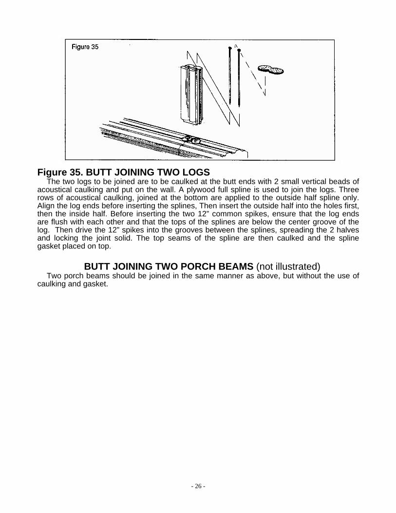
Figure 35. BUTT JOINING TWO LOGS The two logs to be joined are to be caulked at the butt ends with 2 small vertical beads of
acoustical caulking and put on the wall. A plywood full spline is used to join the logs. Three rows of acoustical caulking, joined at the bottom are applied to the outside half spline only. Align the log ends before inserting the splines, Then insert the outside half into the holes first, then the inside half. Before inserting the two 12” common spikes, ensure that the log ends are flush with each other and that the tops of the splines are below the center groove of the log. Then drive the 12” spikes into the grooves between the splines, spreading the 2 halves and locking the joint solid. The top seams of the spline are then caulked and the spline gasket placed on top.
BUTT JOINING TWO PORCH BEAMS (not illustrated) Two porch beams should be joined in the same manner as above, but without the use of
caulking and gasket.
- 27 -
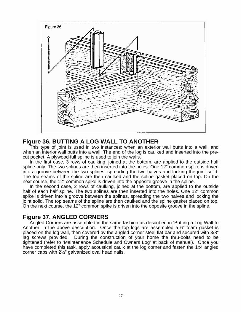
Figure 36. BUTTING A LOG WALL TO ANOTHER This type of joint is used in two instances: when an exterior wall butts into a wall, and
when an interior wall butts into a wall. The end of the log is caulked and inserted into the pre-cut pocket. A plywood full spline is used to join the walls.
In the first case, 3 rows of caulking, joined at the bottom, are applied to the outside half spline only. The two splines are then inserted into the holes. One 12” common spike is driven into a groove between the two splines, spreading the two halves and locking the joint solid. The top seams of the spline are then caulked and the spline gasket placed on top. On the next course, the 12” common spike is driven into the opposite groove in the spline.
In the second case, 2 rows of caulking, joined at the bottom, are applied to the outside half of each half spline. The two splines are then inserted into the holes. One 12” common spike is driven into a groove between the splines, spreading the two halves and locking the joint solid. The top seams of the spline are then caulked and the spline gasket placed on top. On the next course, the 12” common spike is driven into the opposite groove in the spline.
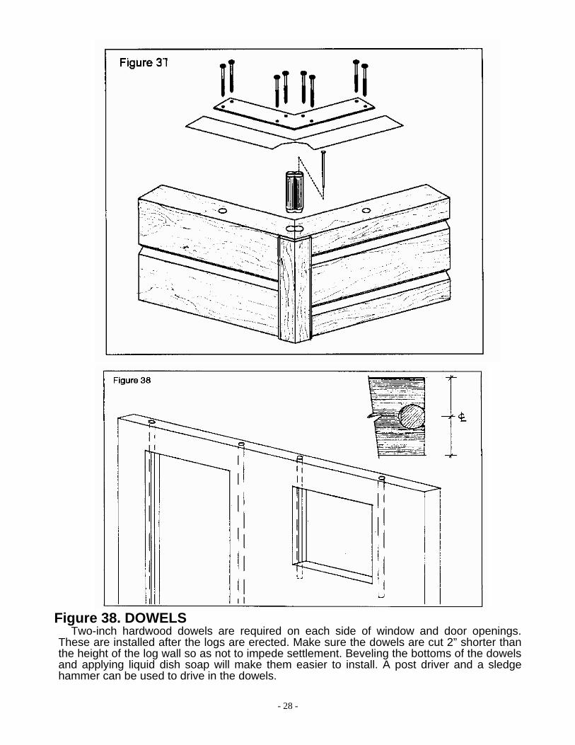
Figure 37. ANGLED CORNERS Angled Corners are assembled in the same fashion as described in ‘Butting a Log Wall to
Another’ in the above description. Once the top logs are assembled a 6” foam gasket is placed on the log wall, then covered by the angled corner steel flat bar and secured with 3/8” lag screws provided. During the construction of your home the thru-bolts need to be tightened (refer to ‘Maintenance Schedule and Owners Log’ at back of manual). Once you have completed this task, apply acoustical caulk at the log corner and fasten the 1x4 angled corner caps with 2½” galvanized oval head nails.
- 28 -
Figure 38. DOWELS Two-inch hardwood dowels are required on each side of window and door openings.
These are installed after the logs are erected. Make sure the dowels are cut 2” shorter than the height of the log wall so as not to impede settlement. Beveling the bottoms of the dowels and applying liquid dish soap will make them easier to install. A post driver and a sledge hammer can be used to drive in the dowels.

- 29 -
Figure 39. ELECTRICAL OUTLETS The standard outlet is pre-drilled up 2 or 1-1/2 logs. A 1-3/8” horizontal hole is pre-drilled
where the outlet box is to be mortised in. After the first course of logs are in place, the 2” pre-drilled electrical holes must be extended through the plywood subfloor. Drill from the top, through the hole in the log and through the subfloor. When there is no subfloor, (in a garage for instance), the holes will be drilled down 88” from the top and marked with a pencil. Over countertops, the holes will be drilled up 55” and marked with a pencil.
Figure 40. SWITCHES AND OUTSIDE LIGHTS
If the holes for exterior lights and switches are not pre-drilled, a wiring channel must be routered beside the hardwood dowel at the side of a door. Horizontal drilling is then done to position switches and lights where desired. The bottom access must be drilled on site as well. Care must be taken when installing the door frame so that no screws or nails hit the wiring.
- 30 -
Figure 41. A. and D. LOG -TO-ROOF AIRSEAL Place 2 beads of caulking atop the log wall and cover with a strip of 12” 6 mil poly. Let the excess
poly hang down to the inside of the log. When the ceiling is insulated, tape the vapour barrier to the strip of poly. At the corners, overlap and caulk the poly strip. Pleat if a continuous barrier is desired.
B. and C. LOG -TO-FLOOR AIRSEAL Place 2 beads of caulking atop the log wall and cover with a strip of air barrier. Be sure there is
enough air barrier to wrap around the floor and extend up the second floor wall a few inches. Let the excess air barrier hang down to the outside of the log until the second floor system is built. When the second floor wall is insulated, tape the interior vapour barrier to the strip of air barrier. On the exterior, the air barrier on the second floor wall should overlap the subfloor. Secure the two air barriers together with red tuck tape.
E. WINDOW AND DOOR AIRSEAL (in conventional frame) (Refer to Figures 84 to 85 regarding airseals for windows and doors in a log wall) Place 2 beads of caulking on all 4 sides of the window (or top and sides of the door frame). Fix the
air barrier to the caulking in a continuous manner around the unit. Apply a bead of caulking across the top and bottom of the rough opening and vertically on the jack studs. Insert the unit into the opening making sure the air barrier adheres to the caulking on the wall. Trim off any excess air barrier and caulk unit in the normal fashion.
F. RIDGE BEAM AIRSEAL Place a strip of 12” 6 mil poly over the beam. When the ceiling vapour barrier is installed, it can be
taped to the poly strip.
G. PARTITION AIRSEAL Place a strip of 12” 6 mil poly atop the stud wall before the 6” partition spikes are nailed in place.
When the ceiling is insulated, tape the vapour barrier to the strip of poly. A similar detail applies when a stud wall intersects an exterior stud wall.
H. CLOSET CEILING AIRSEAL Place a strip of 12” 6 mil poly atop the stud wall before the 6” partition spikes are nailed in place.
Be sure there is enough to extend below the closet ceiling. When the ceiling is insulated, tape the vapour barrier to the strip of poly.
I. MAIN FLOOR TO FOUNDATION SEAL Air barrier to be placed under sill. Let hang down onto concrete block. When logs are in place,
caulk air barrier to them. When basement finished, join vapour barrier to air barrier. J. If B/U beam is placed in beam pocket, seal hidden portion of beam by fabricating an air barrier bag and placing around end of beam. Build bag big enough to be able to cut back and join to vapour barrier.
K. MAIN FLOOR TO PAD FOUNDATION SEAL Poly to go under plywood and run up and be caulked to log wall.
L. CONVENTIONAL FRAME (SUBFLOOR SEAL) Air barrier to go under plate. When floor goes on, take air barrier up over end joist and on top of
plywood. Frame outside walls and tack air barrier to bottom plate. When insulation is complete, bring poly down wall and tape together with air barrier at bottom plate.
M. BASEMENT SEAL When finishing basement insulation, run poly down walls and caulk to concrete floor.
N. CEILING SEAL UPPER FLOOR Run 12” 6 mil poly between plates on double plated walls and attach ceiling poly to each side.
*Note that any breakage of vapour barrier (plumbing, wiring, etc.) will have to be sealed.

- 31 -

- 32 -

- 33 -
O. LOG-TO-GABLE END AIRSEAL
Place 2 beads of caulking atop the log wall and cover with a strip of air barrier. Be sure there is enough air barrier to extend up the gable end wall. Let the excess air barrier hang down to the outside of the log until the gable wall is built. When the gable wall built tape the air barrier to the strip of air barrier. At the corners, overlap and caulk the air barrier strip. Pleat if a continuous barrier is desired.

- 34 -
Figure 42. TRUSSES A vertical temporary brace will go on the end of the building to support the first truss. A
horizontal temporary brace on the top chords will keep the trusses on centre. 1x4 ties, illustrated in the top diagram, are installed on the bottom chord, and diagonally between trusses on the webs, as per the engineered drawings supplied with the trusses. This is to restrain lateral movement.
- 35 -
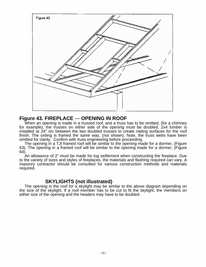
Figure 43. FIREPLACE — OPENING IN ROOF
When an opening is made in a trussed roof, and a truss has to be omitted, (for a chimney for example), the trusses on either side of the opening must be doubled. 2x4 lumber is installed at 24” o/c between the two doubled trusses to create nailing surfaces for the roof finish. The ceiling is framed the same way, (not shown). Note, the truss webs have been omitted for clarity. Confirm with truss engineering before proceeding.
The opening in a TJI framed roof will be similar to the opening made for a dormer, (Figure 63). The opening in a framed roof will be similar to the opening made for a dormer, (Figure 64).
An allowance of 2” must be made for log settlement when constructing the fireplace. Due to the variety of sizes and styles of fireplaces, the materials and flashing required can vary. A masonry contractor should be consulted for various construction methods and materials required.
SKYLIGHTS (not illustrated) The opening in the roof for a skylight may be similar to the above diagram depending on
the size of the skylight. If a roof member has to be cut to fit the skylight, the members on either size of the opening and the headers may have to be doubled.

- 36 -
Figure 44. 2 x 12 LOG SIDING CORNERS When 2x12 siding is used on an outside corner, a piece of 1x8 siding must be ripped
down the centre of the rough face. With the tongue removed, the beveled edges form the corner.
Figure 45. FLOOR JOIST SET-BACK FOR 2x12 Where 2x12 siding is used on a second storey exterior wall, the first joist must be set in
1½”. The gable end studs are erected and the aspenite, air barrier, and 2x12 siding are installed. On the first course of siding, the back half of the groove must be removed to allow for the tongue of the top log. Note, the 2x4 nailer on the inside of the log wall for the finished ceiling. See detail 25A of the Standard Details.

- 37 -
Figure 46. DECORATIVE DOVETAILS The decorative dovetail comes with one 15-degree angle cut. The short edge must be cut
on a 56-degree angle and the bottom cut on a 15-degree angle. The 2x12 siding must be cut accordingly to fit the decorative dovetail. The accuracy of the cuts will determine the appearance of the finished product.
- 38 -
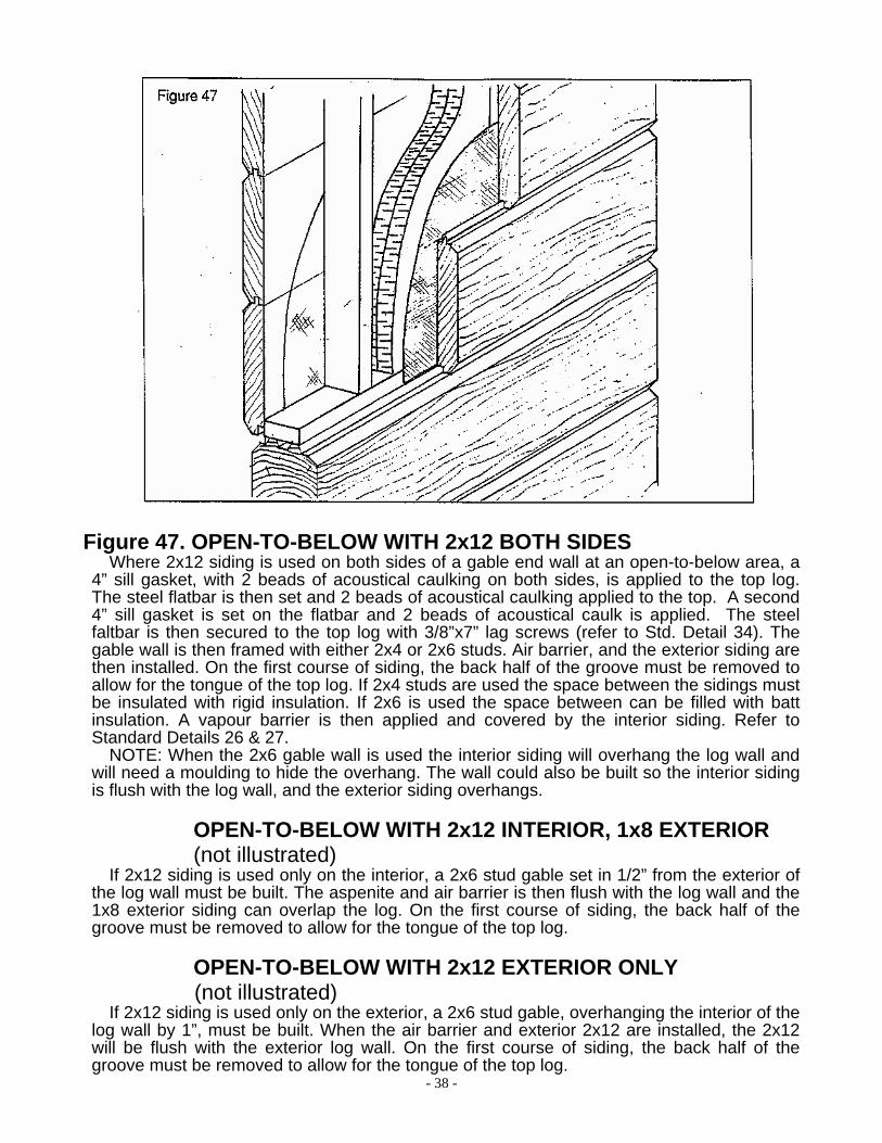
Figure 47. OPEN-TO-BELOW WITH 2x12 BOTH SIDES
Where 2x12 siding is used on both sides of a gable end wall at an open-to-below area, a 4” sill gasket, with 2 beads of acoustical caulking on both sides, is applied to the top log. The steel flatbar is then set and 2 beads of acoustical caulking applied to the top. A second 4” sill gasket is set on the flatbar and 2 beads of acoustical caulk is applied. The steel faltbar is then secured to the top log with 3/8”x7” lag screws (refer to Std. Detail 34). The gable wall is then framed with either 2x4 or 2x6 studs. Air barrier, and the exterior siding are then installed. On the first course of siding, the back half of the groove must be removed to allow for the tongue of the top log. If 2x4 studs are used the space between the sidings must be insulated with rigid insulation. If 2x6 is used the space between can be filled with batt insulation. A vapour barrier is then applied and covered by the interior siding. Refer to Standard Details 26 & 27.
NOTE: When the 2x6 gable wall is used the interior siding will overhang the log wall and will need a moulding to hide the overhang. The wall could also be built so the interior siding is flush with the log wall, and the exterior siding overhangs.
OPEN-TO-BELOW WITH 2x12 INTERIOR, 1x8 EXTERIOR (not illustrated)
If 2x12 siding is used only on the interior, a 2x6 stud gable set in 1/2” from the exterior of the log wall must be built. The aspenite and air barrier is then flush with the log wall and the 1x8 exterior siding can overlap the log. On the first course of siding, the back half of the groove must be removed to allow for the tongue of the top log.
OPEN-TO-BELOW WITH 2x12 EXTERIOR ONLY (not illustrated)
If 2x12 siding is used only on the exterior, a 2x6 stud gable, overhanging the interior of the log wall by 1”, must be built. When the air barrier and exterior 2x12 are installed, the 2x12 will be flush with the exterior log wall. On the first course of siding, the back half of the groove must be removed to allow for the tongue of the top log.

- 39 -
Figure 48. SECOND FLOOR ON FRAMED MAIN FLOOR When a second floor is built over a 2x12 framed section, the end joist must be set out
1-1/2” from the stud wall below. Blocking is installed at 24” o/c between the last two joists to provide support for both the end joist and the gable wall. 7/16” aspenite, air barrier, and 1x8 siding can then be installed. The 1x8 overlaps the 2 x 12 creating a drip edge.
If 2x12 siding is used on the second floor, the end joist would be set flush with the stud wall below.
Figure 49. GABLE END ON TRUSS WITH 2x12 Where 2x12 siding is used on a gable end truss, the truss must be set in 2” from the log wall.
Aspenite, air barrier and siding are then installed. On the first course of siding, the back half of the groove must be removed to allow for the tongue of the top log. A 2x4 is nailed on its flat to the inside of the top log. This provides a nailing surface for the finished ceiling.

- 40 -
Figure 50. TRUSS ROOF ON FRAMED MAIN FLOOR When a trussed roof is built over a 2x12 framed section, the face of the end truss must
be set even with the stud wall below. The end truss must be horizontally strapped with 2x4 lumber 24” o/c. 7/16” aspenite, air barrier, and 1x8 siding can then be installed. The 1x8 overlaps the 2x12 creating a drip edge.

- 41 -
Figure 51. SETTLEMENT ALLOWANCE AT 2x12 EXTERIOR SIDING Where a framed structure, such as a garage, has a roof that ties into the roof of a log
structure, the framed structure’s roof must be adjusted downwards as the logs settle. The stud wall will usually be 2x6 stud spaced 16” o/c to allow for the teleposts. A built-up beam, (size as per blueprints), is installed over the stud wall where joists, rafters, or trusses are bearing. It will be supported by teleposts. The teleposts should be placed with the adjustors at the bottom. A pocket cut into the log wall usually supports one end of the beam. A 1-1/2” space is required between the top plate of the wall and the bottom of the beam. The stud wall at the gable end is built with a 1-1/2” space above it as well. Aspenite is then installed over the stud wall. If a 4-ply beam is used, aspenite is not required on the beam since it is already 1/2” wider than the 2x6 wall. Air barrier is then stapled over the aspenite, 1-1/2” space, and beam.
Next, the 2x12 siding is installed. At the gable end, the 1x8 siding overlaps the 2x12, so no allowance for settlement is required, (see Figures 48 and 50). Where the 2x12 siding is under the soffit, the allowance for settlement must be made between the top two courses of siding. A 1-1/2” piece, including the groove, must be cut from the top course of 2x12 (see inset). That strip is then nailed to the aspenite. The top course of siding is then nailed to the beam so there is a space of 1-1/2” between it and the course below. As the beam is adjusted down, the top course of 2x12 will slide over the grooved strip.
Another method is to leave a 1-1/2” space between the two courses of siding. The space can be covered with a piece of trim.
SETTLEMENT ALLOWANCE AT 2x12 INTERIOR SIDING (not illustrated)
Where 2x12 siding extends from the main floor to the upper floor, a slip joint in the siding must be made where the 1-1/2” settlement allowance has been left above the partition. This joint is made as illustrated in this figure. A 1-1/2” piece, including the groove, must be cut from the upper course of 2x12 (see inset). That strip is then nailed to the stud wall. The upper course of siding is then nailed to the beam or floor joist so there is a space of 1-1/2” between it and the course below. As the beam or floor is adjusted down, the upper course of 2x12 will slide over the grooved strip.
Another method is to leave a 1-1/2” space between the two courses of siding. The space can be covered with a piece of trim.
- 42 -
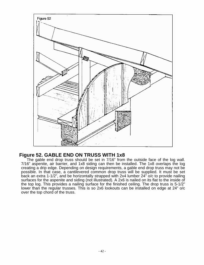
Figure 52. GABLE END ON TRUSS WITH 1x8
The gable end drop truss should be set in 7/16” from the outside face of the log wall. 7/16” aspenite, air barrier, and 1x8 siding can then be installed. The 1x8 overlaps the log creating a drip edge. Depending on design requirements, a gable end drop truss may not be possible. In that case, a cantilevered common drop truss will be supplied. It must be set back an extra 1-1/2”, and be horizontally strapped with 2x4 lumber 24” o/c to provide nailing surfaces for the aspenite and siding (not illustrated). A 2x6 is nailed on its flat to the inside of the top log. This provides a nailing surface for the finished ceiling. The drop truss is 5-1/2” lower than the regular trusses. This is so 2x6 lookouts can be installed on edge at 24” o/c over the top chord of the truss.

- 43 -
Figure 53. INTERIOR GABLE WITH SCISSOR TRUSS AND 1x8
With a scissor trussed roof, 2x4 studs must be used to build an interior gable end atop the log wall. The studs are spaced 16” o/c and single top and bottom plates are used. The top plate should be even with the top surface of the bottom chord of the scissor trusses. This can be determined by positioning a scissor truss along side the gable end truss and marking its location. A 2x4 is attached to the side of the interior gable at the same height as the bottom chord of the scissor truss. This acts as a nailer for the finished ceiling. The interior gable should be insulated with 6” batts with vapour barrier.
INTERIOR GABLE WITH SCISSOR TRUSS AND 2x12 (not illustrated)
If 2x12 siding is to be installed on one side, a scissor truss must be used on the end, rather than a gable end truss. The 2x4 interior gable will be built under the bottom chord of the scissor truss. Position the truss and interior gable so the 2x12 siding will be flush with the log wall. If 2x12 siding is to be installed on both sides, this gable end can be constructed in the same manner as Figure 47 (Open-To-Below with 2x12 Both Sides). This will allow the 2x12 siding on both sides to be near flush with the log wall.

- 44 -
Figure 54 FRAMED GABLE END If 1x8 exterior siding is used, the first joist and the gable wall should be set in 1/2” from the
exterior of the log wall (as shown) so the 1x8 siding can overlap the log creating a drip edge. If 2x12 exterior siding is being used, the first joist and the gable wall should be set in 1½” as per Figure 46. The gable wall is usually constructed of 2x6 studs spaced 16” o/c with a single bottom plate and a double top plate. The size of the lintels over windows will be noted either on the blueprints or on the supplied material list. 7/16” aspenite, air barrier and the exterior siding are then attached to the framing (not illustrated). Reference Figure 75b if a drip cap is required over a window or door.
RAKE 2x6 lookouts at 24” o/c are used to create the rake overhang. The lookouts pass over the
framed gable end (or drop gable truss) and extend in to the first rafter. The 2x6 subfascia is then attached to the end of the lookouts. The lookouts have created the overhang as well as a nailing surface for the soffit.
- 45 -
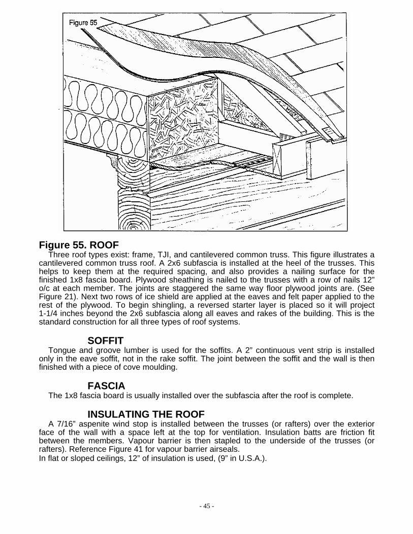
Figure 55. ROOF Three roof types exist: frame, TJI, and cantilevered common truss. This figure illustrates a
cantilevered common truss roof. A 2x6 subfascia is installed at the heel of the trusses. This helps to keep them at the required spacing, and also provides a nailing surface for the finished 1x8 fascia board. Plywood sheathing is nailed to the trusses with a row of nails 12” o/c at each member. The joints are staggered the same way floor plywood joints are. (See Figure 21). Next two rows of ice shield are applied at the eaves and felt paper applied to the rest of the plywood. To begin shingling, a reversed starter layer is placed so it will project 1-1/4 inches beyond the 2x6 subfascia along all eaves and rakes of the building. This is the standard construction for all three types of roof systems.
SOFFIT Tongue and groove lumber is used for the soffits. A 2” continuous vent strip is installed
only in the eave soffit, not in the rake soffit. The joint between the soffit and the wall is then finished with a piece of cove moulding.
FASCIA The 1x8 fascia board is usually installed over the subfascia after the roof is complete.
INSULATING THE ROOF A 7/16” aspenite wind stop is installed between the trusses (or rafters) over the exterior
face of the wall with a space left at the top for ventilation. Insulation batts are friction fit between the members. Vapour barrier is then stapled to the underside of the trusses (or rafters). Reference Figure 41 for vapour barrier airseals. In flat or sloped ceilings, 12” of insulation is used, (9” in U.S.A.).

- 46 -
Figure 56. SCREWJACK — INTERIOR
A hole is drilled in the bottom of the post to allow for the threaded portion of the screwjack during adjustment. The lower plate is to be nailed to the floor, and the upper plate to the post. The screwjack can be finished off with the baseboard trim. Nailing the trim together to form a moveable sleeve rather than nailing it to the post makes future settling adjustment easy.
Figure 57. 6x11 AND 6x12 (or 8x12) STRUCTURAL FLOOR BEAMS
Hangers will be supplied if a 6x11 and 6x12 (or 8x12) beamed floor is used. The face mounted hangers come pre-drilled for nails and screws. When installing the hangers, be aware that the hangers are shorter than the beams. Therefore, the hangers will not be set flush to the top of the log wall. Each beam will be pre-cut and lettered. Reference the blueprints for this letter.
- 47 -
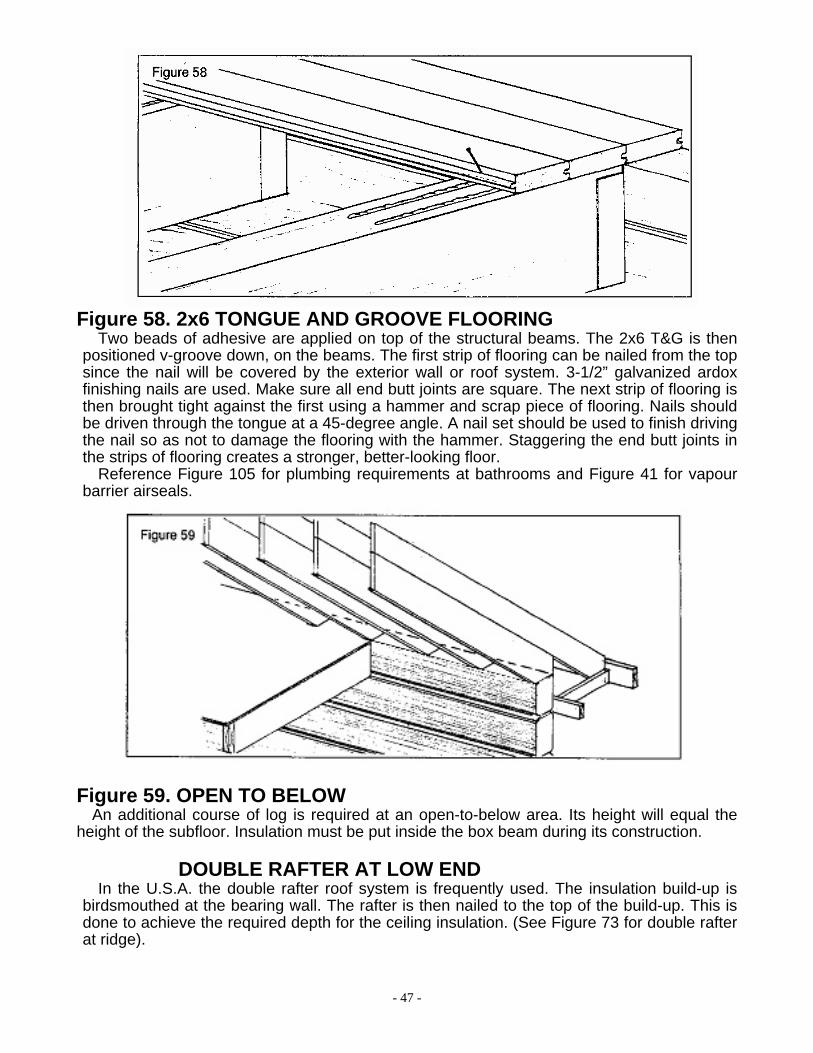
Figure 58. 2x6 TONGUE AND GROOVE FLOORING Two beads of adhesive are applied on top of the structural beams. The 2x6 T&G is then
positioned v-groove down, on the beams. The first strip of flooring can be nailed from the top since the nail will be covered by the exterior wall or roof system. 3-1/2” galvanized ardox finishing nails are used. Make sure all end butt joints are square. The next strip of flooring is then brought tight against the first using a hammer and scrap piece of flooring. Nails should be driven through the tongue at a 45-degree angle. A nail set should be used to finish driving the nail so as not to damage the flooring with the hammer. Staggering the end butt joints in the strips of flooring creates a stronger, better-looking floor.
Reference Figure 105 for plumbing requirements at bathrooms and Figure 41 for vapour barrier airseals.
Figure 59. OPEN TO BELOW
An additional course of log is required at an open-to-below area. Its height will equal the height of the subfloor. Insulation must be put inside the box beam during its construction.
DOUBLE RAFTER AT LOW END In the U.S.A. the double rafter roof system is frequently used. The insulation build-up is
birdsmouthed at the bearing wall. The rafter is then nailed to the top of the build-up. This is done to achieve the required depth for the ceiling insulation. (See Figure 73 for double rafter at ridge).
- 48 -
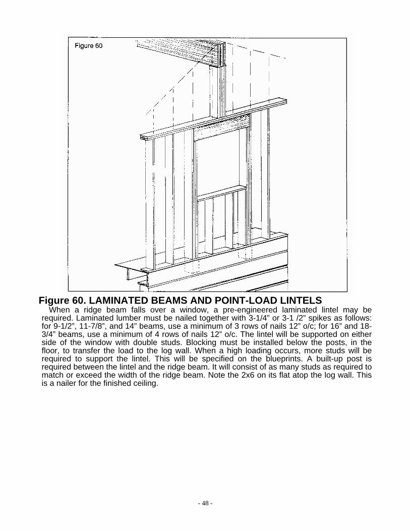
Figure 60. LAMINATED BEAMS AND POINT-LOAD LINTELS When a ridge beam falls over a window, a pre-engineered laminated lintel may be
required. Laminated lumber must be nailed together with 3-1/4” or 3-1 /2” spikes as follows: for 9-1/2”, 11-7/8”, and 14” beams, use a minimum of 3 rows of nails 12” o/c; for 16” and 18-3/4” beams, use a minimum of 4 rows of nails 12” o/c. The lintel will be supported on either side of the window with double studs. Blocking must be installed below the posts, in the floor, to transfer the load to the log wall. When a high loading occurs, more studs will be required to support the lintel. This will be specified on the blueprints. A built-up post is required between the lintel and the ridge beam. It will consist of as many studs as required to match or exceed the width of the ridge beam. Note the 2x6 on its flat atop the log wall. This is a nailer for the finished ceiling.

- 49 -
Figure 61. SHED DORMER The shed wall is usually constructed of 2x6 studs spaced 16” o/c with a single bottom plate
and a double top plate. The size of the lintels over windows will be noted either on the blueprints or on the supplied material list. 7/16” aspenite and air barrier are then attached to the framing. Reference Figure 75b if a drip cap is required over a window or door. After the false roof is built and shingled, (see below), wall to roof flashing (see Figure 75c), and the siding are then installed.
- 50 -
FRAMED SHED ROOF The ceiling joists and the birdsmouthed rafters bear on the double top plate of the shed
wall. Lookouts (not shown) are then installed as per Figure 54. The 2x6 subfascia is then installed and the roof sheathing is nailed in place. 2 rows of ice sheild is then applied at the eave and felt paper to the rest of the plywood. To begin shingling, a reversed starter layer is placed so it will project 1-1/4 inches beyond the 2x6 subfascia along the eave and rakes. The 1x8 fascia board is usually installed over the subfascia after all roofs are complete.
INSULATING THE WALLS In the shed dormerwalls, gable dormerwalls, and gable ends, 6” of insulation is required. In special
cases where the framed walls are 2x4, 3-1/2” of insulation is required.
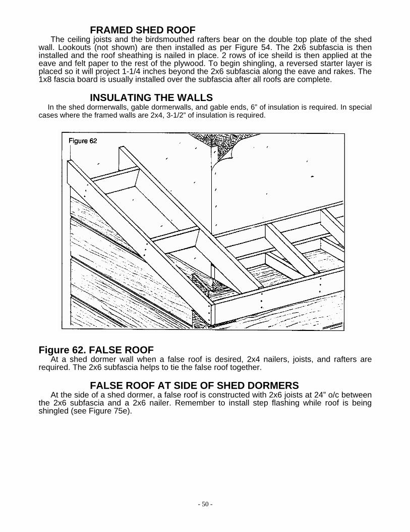
Figure 62. FALSE ROOF
At a shed dormer wall when a false roof is desired, 2x4 nailers, joists, and rafters are required. The 2x6 subfascia helps to tie the false roof together.
FALSE ROOF AT SIDE OF SHED DORMERS At the side of a shed dormer, a false roof is constructed with 2x6 joists at 24” o/c between
the 2x6 subfascia and a 2x6 nailer. Remember to install step flashing while roof is being shingled (see Figure 75e).

- 51 -
Figure 63. GABLE DORMER ATOP ROOF A gable dormer can sit atop either a TJI framed roof or a standard framed roof. A TJI roof
is illustrated here. The dormer walls are built atop the roof sheathing with a single bottom plate and a double top plate keeping in mind the ceiling height required. The studs are usually 2x6 lumber spaced 16” o/c. The size of the window lintel will be noted either on the blueprints or in the supplied material list. The rafters are held at the base by a birdsmouth notch over the stud wall, and at the top by a ridge board. The 2x4 framed gable end will support 2x6 lookouts at 24” o/c, between the subfascia and the first rafter. These lookouts will provide the overhang and nailing surface for the soffit (as shown in Figure 54). The first ceiling joist is laid on its flat, to provide a nailing surface for the finishing ceiling. Ceiling joists are run at right angles between the header in the main roof system and the last ceiling joist bearing on the dormer wall. A 2x4 nailer is required at the side of the dormer to support the soffit material. If the overhang exceeds a foot, a 2x4 joist is required between the nailer and the rafter. 7/16” aspenite is then attached to the framing. Reference Figure 75b if a drip cap is required over the window. The 2x6 subfascia is then installed and the roof sheathing is nailed in place. Two rows of ice shield protection at the eaves and one row at the valleys is then applied to the plywood. Valley flashing is then installed (see Figure 75h). To begin shingling, a reversed starter layer is placed so it will project 1-1/4 inches beyond the 2x6 subfascia along the eave and rakes. Step flashing must be installed at the sides of the dormer during shingling (see Figure 75e). Wall to roof flashing (see Figure 75c), air barrier, and the siding can then be installed. The 1x8 fascia board is usually installed over the subfascia after all roofs are complete.
MAIN BUILDING TJI RAFTERS TJI rafters at the sides of the opening, and the headers, should be sized as per the
blueprints. They will usually be doubled.
- 52 -

- 53 -
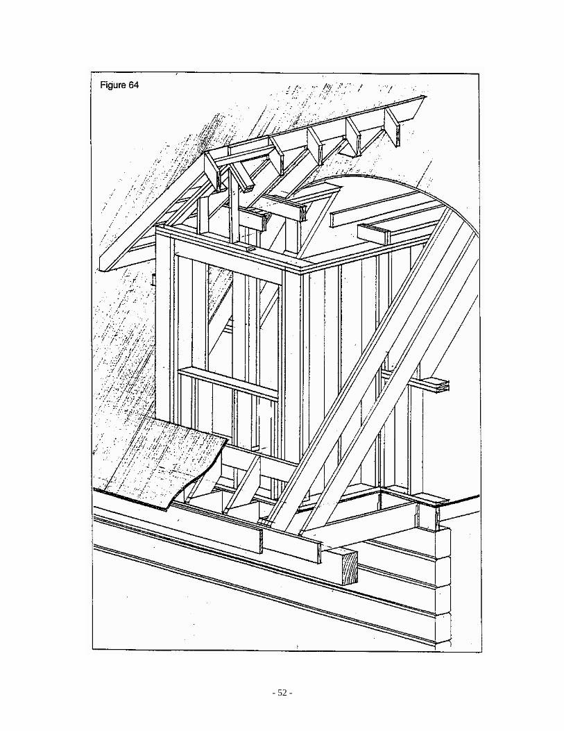
Figure 64. GABLE DORMER ON FLOOR
A gable dormer can sit on the floor with either a TJI framed or a standard framed roof. A framed roof is illustrated here. The dormer walls are built atop the floor with a single bottom plate and a double top plate. The studs are usually 2x6 lumber spaced 16” o/c. Where the gable wall extends in beyond the kneewall, it must be scabbed to the rafters at each side of the dormer. The size of the window lintel will be noted either on the blueprints or in the supplied material list. The dormer rafters are held at the base by a birdsmouth notch over the stud wall, and at the top by a ridge board. The 2x4 framed gable end will support 2x6 lookouts at 24” o/c, between the subfascia and the first rafter. These lookouts will provide the overhang and nailing surface for the soffit (as shown in Figure 54). The first ceiling joist is laid on its flat, to provide a nailing surface for the finished ceiling. Where the main roofs ceiling joists come into the dormer, they will be spiked to the last dormer ceiling joist, which is doubled. A 2x4 nailer is required at the side of the dormer to support the soffit material. If the overhang exceeds a foot, a 2x4 joist is required between the nailer and the rafter. A nailer is required across the front of the dormer at the bottom to carry the short main roof rafters coming in to it. 7/16” aspenite is then attached to the framing. Reference Figure 75b if a drip cap is required over the window. The 2x6 subfascia is then installed and the roof sheathing is nailed in place. Two rows of ice shield protection at the eaves and one row at the valleys is then applied to the plywood. Valley flashing is then installed (see Figure 75h). To begin shingling, a reversed starter layer is placed so it will project 1-1/4 inches beyond the 2x6 subfascia along the eave and rakes. Step flashing must be installed at the sides of the dormer during shingling (see Figure 75e). Wall to roof flashing (see Figure 75c), air barrier, and the siding can then be installed. The 1x8 fascia board is usually installed over the subfascia after all roofs are complete.
KNEEWALL Kneewalls are usually constructed of 2x6 studs at 16” o/c with a single bottom plate and a
double top plate. Its height will be specified on the blueprints. In this illustration, the main roof rafters are supported by the floor joists that span from the log wall to the porch beam. The kneewall and insulation build-up can then be installed under the rafter. See Figure 65 for a rafter supported by the wall instead of the joists.
MAIN BUILDING RAFTERS AND JOISTS Double rafters and headers are required in the roof around the dormer opening. Doubled
joists are required under the side dormer walls, and blocking is required under the front wall. The joists over the porch will either be continuous from the main structure with blocking under the kneewall, or separate, hangered to an end joist.
INSULATING THE FLOOR All floors with an unheated area below require 8” of insulation, (6” in U.S.A.). This applies
to dormers over a porch, and floors over garages.
- 54 -
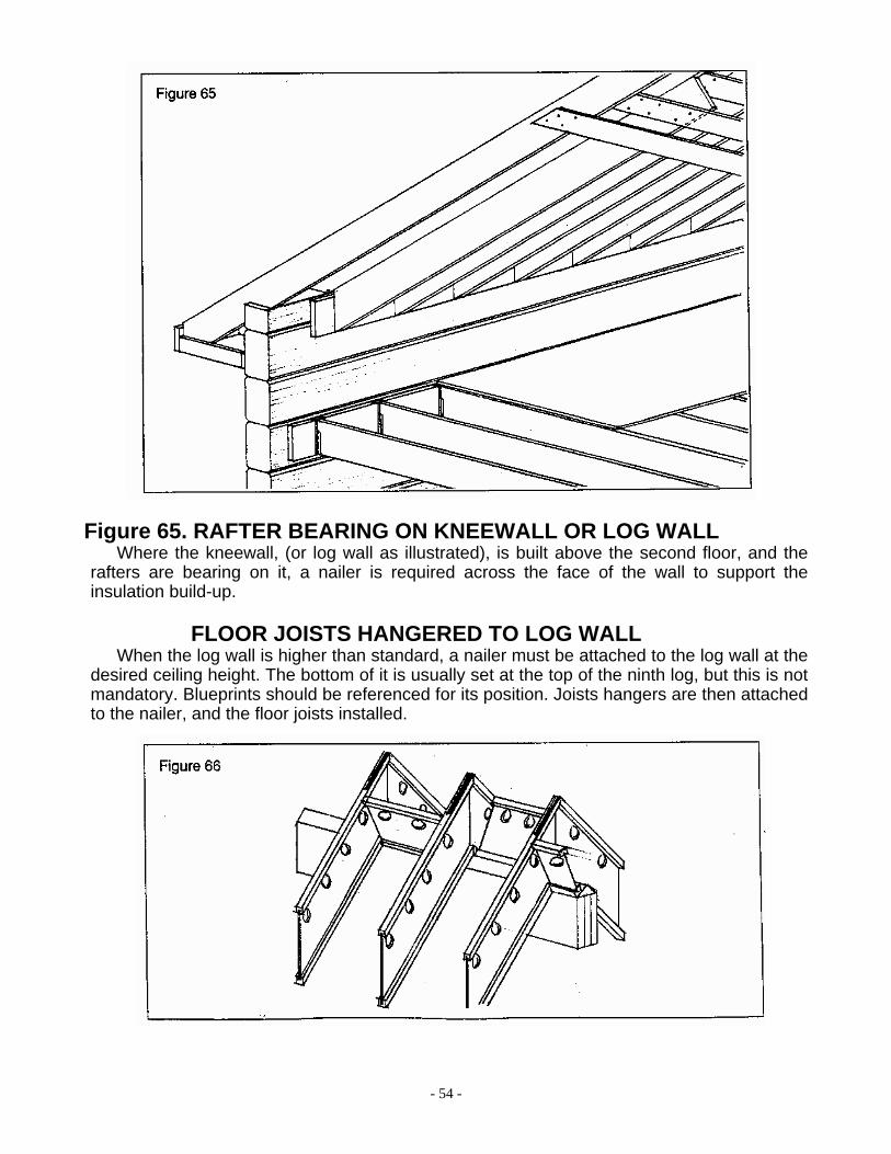
Figure 65. RAFTER BEARING ON KNEEWALL OR LOG WALL
Where the kneewall, (or log wall as illustrated), is built above the second floor, and the rafters are bearing on it, a nailer is required across the face of the wall to support the insulation build-up.
FLOOR JOISTS HANGERED TO LOG WALL When the log wall is higher than standard, a nailer must be attached to the log wall at the
desired ceiling height. The bottom of it is usually set at the top of the ninth log, but this is not mandatory. Blueprints should be referenced for its position. Joists hangers are then attached to the nailer, and the floor joists installed.

- 55 -
Figure 66. TJI RAFTERS BEARING AT RIDGE The laminated ridge must be nailed together with 3-1/4” or 3-1/2” spikes as follows: for 9-
1/2”, 11-7/8”, and 14” beams, use a minimum of 3 rows of nails 12” o/c; for 16” and 18-3/4” beams, use a minimum of 4 rows of nails 12” o/c. Place a strip of poly over the beam. When the ceiling vapour barrier is installed, it can be taped to the poly strip (see Figure 41f). Where each side is of equal pitch, a double beveled plate must be cut and positioned atop the ridge beam. It can be made in pieces, or it can be continuous. Butt the TJI rafters at the ridge and secure to the plate with 2 – 3” common nails each side of the joist. Nail a 24” metal strap across the butt joint of the rafters using 18 – 1½” nails. Three rows of joist truss blocking are required between the rafters for lateral support: 1 row at the peak (alternating sides), and 1 row at each lower bearing points
.
Figure 67. DUAL PITCH TJI RAFTER SUPPORT
When the two sides have unequal pitches and the peak must be centered on the building, supports under the TJI rafters must be cut as shown instead of the double beveled plate. If design permits the peak being off-centered, a double beveled plate can be used as shown in Figure 66. The bevels would be at different angles in this case.

- 56 -
Figure 68. TJI RAFTER BEARING AT LOW END
The TJI rafter flange is nailed (2 - 3” common nails each side) to a 2x_ beveled bearing plate at the lower bearing point. TJI shear blocking is required both sides of each rafter. A 2x4 nailer is required along the house wall to support the 2x4 soffit nailers that run along one side of the TJI rafters.
OVERHANGS ON GABLE ENDS WITH TJI RAFTERS
Figure 68 illustrates a 4 foot overhang at the gable end. The lookouts are 2 x 6 lumber that extend into the double 16” TJI rafter. The lookouts will bear on the gable end frame wall with the ends being notched around the top flange of the TJI. The size of the overhang equals the distance the first TJI rafter will be set in from the gable end. Whenever the overhang exceeds 2 feet, the first rafter will need to be doubled. Your blueprints will specify which method is used.

- 57 -
Figure 69. LAMINATED VALLEY WITH TJI RAFTERS Plywood web stiffeners are required on both sides of the TJI rafters where they are
hangered to the laminated valley. This figure illustrates a vented TJI rafter. Depending on the design requirements, rafters may be used in lieu of TJI’s.
Figure 70. RIDGE OVERHANG
Plywood web stiffeners are required on both sides of the joist trusses where they are hangered to the wall or beam. A beveled plate must be cut and placed atop the wall or beam. A 2x4 outrigger is attached to the side of the joist truss to strengthen the overhang and to provide a nailing surface for the soffit and subfascia.

- 58 -
Figure 71. TJI RAFTERS WITH LOW PITCH When TJI rafters are used at a low pitch, (on a shed dormer for example), it may have to
be cut as shown to maintain an adequate heel height. Not doing this would result in a very large overhang, which may not suit the design of the building. A 2x4 is nailed between the rafters to provide a nailing surface for the aspenite and siding. A 2x4 is nailed to one side of the TJI rafters to provide a nailing surface for the soffit. A row of TJI shear blocking (not illustrated) is required between the joist trusses for lateral restraint. The exterior sheathing and siding will extend up to the soffit, above the top plates of the wall.

- 59 -
Figure 72. PORCH ROOF WITH TJI RAFTERS Porch rafters rest on the 2x4 ceiling joists and are nailed to a 2x6 bearing plate that is
nailed across the TJI rafters at the heel of the porch rafter. The ceiling joists rest on the porch beam and nail into 2x4 blocking nailed between the TJI rafters. Where the porch roof plywood is attached at the roof pitch change, a 2x4 nailer is required under the plywood and between the TJI rafters.
Figure 73. SHINGLED RIDGE VENT This continuous roll vent is used on all roof types, including truss and TJI cathedral, where
shingles are used. A minimum space of 2” is required at the ridge under the vent. Note: the vent is not installed at the roof overhang. Nail shingles to the top of the vent once it is secured to the roof.
OTHER ROOF VENTS (not illustrated)
Other types of venting which may be used include square roof vents, cupolas, and gable vents. The unobstructed opening in the roof plywood must be the same size as the opening in the vent.
DOUBLE RAFTER AT RIDGE In the U.S.A. the double rafter roof system is frequently used. The insulation build-up is
birdsmouthed at the ridge. The rafter is then nailed to the top of the build-up. This is done to achieve the required depth for the ceiling insulation (See Figure 59 for double rafter at the low end).
- 60 -
Figure 74. CEDAR SHAKE ROOF On a trussed roof, the heel of the truss, (or on a framed roof, the heel of the rafter), is
reduced to accommodate the 2 x 4 strapping. The first row of strapping is placed against the subfascia. The center of the second row of strapping is 9-1/2” from the outside face of the subfascia. The remaining rows of strapping are spaced 9-1/2” o/c (confirm the spacing with the blueprints). In some cases, plywood is used in lieu of strapping. The first row of ice shield is placed over the subfascia and first row of strapping. A row of shakes, spaced about 1/4” apart, is placed over it. Another row of shakes is placed directly over the first row to create a double starter strip. Use two nails in each shake, 1” from the edge, and 1-1/2” above the exposure line. Be sure to offset the side joints at least 1-3/4” from the previous course. After the second row of ice shield is laid, alternate 15lb. felt and shakes until the ridge is reached. The final course will be a half shake. The ridge is then capped with a strip of felt paper. Shakes are placed lengthwise and alternatively lapped to create the ridge caps. A piece of felt is used between each cap as well. If a ridge vent is used, (see Figure 73), the ridge does not have to be capped with a strip of felt paper. The shake ridge caps are installed directly on top of the ridge vent.
STEEL ROOFS (not illustrated)
As shown in Fig.74, the heel height of the truss or rafter must be reduced to accommodate the 2x4 strapping. The first row of strapping is placed against the subfascia. The remaining rows are spaced 24” o/c. The air barrier underlay, steel roofing and vents should be installed as per the steel manufacturers recommendations. In many cases plywood is used in lieu of strapping.
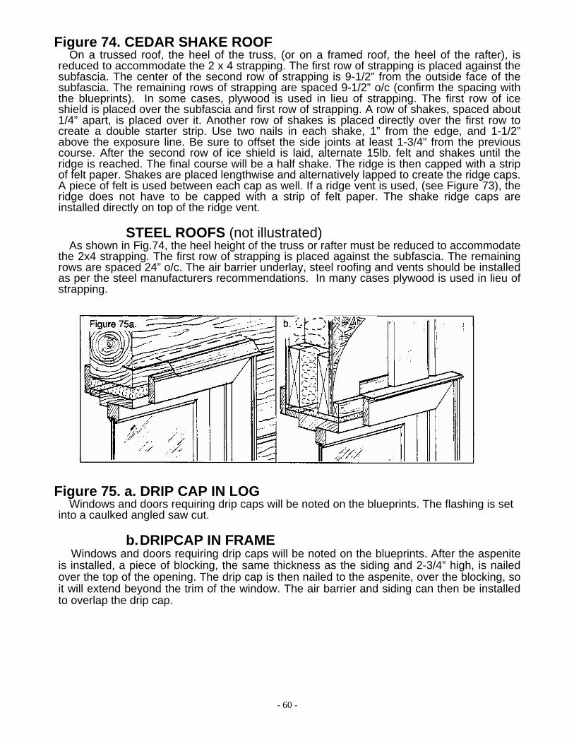
Figure 75. a. DRIP CAP IN LOG
Windows and doors requiring drip caps will be noted on the blueprints. The flashing is set into a caulked angled saw cut.
b. DRIPCAP IN FRAME Windows and doors requiring drip caps will be noted on the blueprints. After the aspenite
is installed, a piece of blocking, the same thickness as the siding and 2-3/4” high, is nailed over the top of the opening. The drip cap is then nailed to the aspenite, over the blocking, so it will extend beyond the trim of the window. The air barrier and siding can then be installed to overlap the drip cap.

- 61 -
c. WALL TO ROOF FLASHING When a wall comes into a roof, in front of a dormer for instance, wall to roof flashing is
required. The top is nailed to the wall over the aspenite and the air barrier and siding overlap it. The bottom is exposed, overlapping the shingles.
d. WALLTO ROOF VENT When a wall comes into a roof and a vent is required, wall to roof vent/flashing is required.
The top is nailed to the wall over the aspenite and the air barrier and siding overlap it. The bottom is exposed, overlapping the shingles.
e. STEP FLASHING When a roof intersects a wall parallel to the slope, at the side of a dormer or at a gable
end for instance, step flashing is required at each shingle course. The top of each piece is nailed to the aspenite and the air barrier and siding overlap it. The bottom overlaps the shingle. It will be covered by the next shingle course.
f. COUNTER FLASHING IN LOG When a roof comes into a log wall, counter flashing is required. Step flashing must be
installed as above. A second piece of flashing is set into a caulked angled saw cut in the log, and it overlaps the step flashing. A 1-1/2” space must be left between the bottom of the second flashing and the roof to allow for any log settlement.
- 62 -
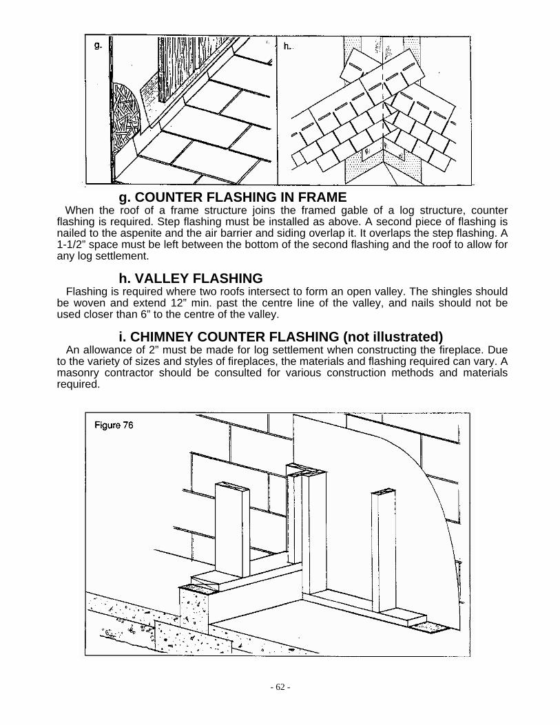
g. COUNTER FLASHING IN FRAME When the roof of a frame structure joins the framed gable of a log structure, counter
flashing is required. Step flashing must be installed as above. A second piece of flashing is nailed to the aspenite and the air barrier and siding overlap it. It overlaps the step flashing. A 1-1/2” space must be left between the bottom of the second flashing and the roof to allow for any log settlement.
h. VALLEY FLASHING Flashing is required where two roofs intersect to form an open valley. The shingles should
be woven and extend 12” min. past the centre line of the valley, and nails should not be used closer than 6” to the centre of the valley.
i. CHIMNEY COUNTER FLASHING (not illustrated) An allowance of 2” must be made for log settlement when constructing the fireplace. Due
to the variety of sizes and styles of fireplaces, the materials and flashing required can vary. A masonry contractor should be consulted for various construction methods and materials required.
- 63 -
Figure 76. BASEMENT PARTITIONS
A sill gasket must be placed beneath all partitions that seat on the concrete floor. A moisture barrier must be placed against the concrete wall before a partition can be built next to it. Insulation and vapour barrier can then be installed.
BASEMENT BEARING PARTITIONS A continuous footing and one course of block is required under a bearing wall. The block
is omitted at doorways. A sill gasket is required between the block and the bottom plate of the stud wall.
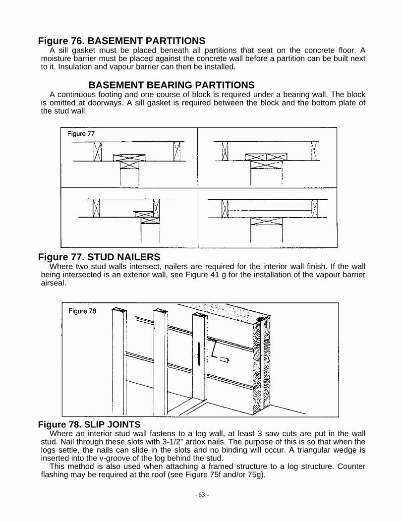
Figure 77. STUD NAILERS Where two stud walls intersect, nailers are required for the interior wall finish. If the wall
being intersected is an exterior wall, see Figure 41 g for the installation of the vapour barrier airseal.
Figure 78. SLIP JOINTS Where an interior stud wall fastens to a log wall, at least 3 saw cuts are put in the wall
stud. Nail through these slots with 3-1/2” ardox nails. The purpose of this is so that when the logs settle, the nails can slide in the slots and no binding will occur. A triangular wedge is inserted into the v-groove of the log behind the stud.
This method is also used when attaching a framed structure to a log structure. Counter flashing may be required at the roof (see Figure 75f and/or 75g).
- 64 -
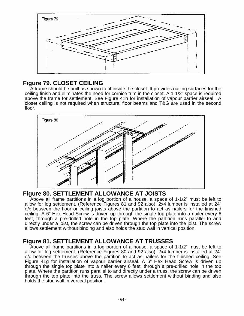
Figure 79. CLOSET CEILING
A frame should be built as shown to fit inside the closet. It provides nailing surfaces for the ceiling finish and eliminates the need for cornice trim in the closet. A 1-1/2” space is required above the frame for settlement. See Figure 41h for installation of vapour barrier airseal. A closet ceiling is not required when structural floor beams and T&G are used in the second floor.
Figure 80. SETTLEMENT ALLOWANCE AT JOISTS Above all frame partitions in a log portion of a house, a space of 1-1/2” must be left to
allow for log settlement. (Reference Figures 81 and 92 also). 2x4 lumber is installed at 24” o/c between the floor or ceiling joists above the partition to act as nailers for the finished ceiling. A 6” Hex Head Screw is driven up through the single top plate into a nailer every 6 feet, through a pre-drilled hole in the top plate. Where the partition runs parallel to and directly under a joist, the screw can be driven through the top plate into the joist. The screw allows settlement without binding and also holds the stud wall in vertical position.
Figure 81. SETTLEMENT ALLOWANCE AT TRUSSES
Above all frame partitions in a log portion of a house, a space of 1-1/2” must be left to allow for log settlement. (Reference Figures 80 and 92 also). 2x4 lumber is installed at 24” o/c between the trusses above the partition to act as nailers for the finished ceiling. See Figure 41g for installation of vapour barrier airseal. A 6” Hex Head Screw is driven up through the single top plate into a nailer every 6 feet, through a pre-drilled hole in the top plate. Where the partition runs parallel to and directly under a truss, the screw can be driven through the top plate into the truss. The screw allows settlement without binding and also holds the stud wall in vertical position.

- 65 -
Figure 82. DOOR HEADERS
The framed opening size will depend on the size of the door or passage required. 2x4 or 2x6 lumber will be used for the header, depending on the thickness of the wall. Studs on either side of the opening support the lintel. Filler studs are nailed in place over the lintel.
Figure 83. INTERIOR DOORS
The door frame consists of two side jambs and a head jamb, each with separate door stops. The jambs should be nailed together at the corners to coincide with the size of the rough opening of the door. The frame is set by using shims between the side jambs and the studs of the wall. Once the jambs are square and plumb, nail them to the studs, through the shims. The nails should be positioned as shown so they can be hidden by the door stop. The shims can then be cut flush with the face of the wall. The door is then cut to height, depending on the floor finish to be used. Router the door for the hinges to sit square and flush with the edge. The hinges are then screwed to the door. Drilling can now be done for passage or lock sets. The door is then placed into the opening and blocked at the bottom. The hinge locations are marked on the jamb and are routered. The second halves of the hinge are fastened to the jamb. The door is put into place and the hinge pins inserted. Make sure that the door closes with the proper clearances. The top doorstop can be temporarily nailed in place, and the passage set installed. The strike plate is then positioned, drilled and routered in accordance with the position of the latch. After the strike plate is screwed in place, the top door stop can be adjusted if necessary, and the side door stops nailed into place. The door can now be trimmed.

- 66 -
Figure 84. DOOR OPENINGS
In a log wall, the rough opening widths are pre-cut at the factory. The rough opening heights are taken to the nearest full log and must be cut to size on site. The opening height required, which already includes an allowance for log settlement, is stated in the window and door schedule on the blueprints. A 6” gasket is installed at each side and at the bottom of the opening. Acoustical caulking is applied between the sill gasket and logs, and under the door. A 2x6 subjamb is screwed to the 2” hardwood dowel with 3” No. 10 screws at 12” o/c. A 1/8” pilot hole is recommended. The 2x6 subjamb must be cut 1-1/2” shorter than the rough opening height. This 1-1/2” space must be left at the top to allow the log to settle. Shims are used to level and square the unit. Shims must be installed at the lock and hinge points, expanding spray foam insulation can be used to fill the spaces around the unit except for the top. The 1-1/2” space above the unit must be filled with batt insulation that is loosely fit so as not to impede the log settlement. The air seal is completed by sealing a piece of air barrier to the Door frame, foam, and Log.
When installing a door in a framed wall and a drip cap is required, reference Figure 75b.
1 x 4 EXTERIOR TRIM Windows and doors will have the 1x4 exterior trim shipped separately for site installation.
Acoustical caulking is applied on the back of the exterior trim where it attaches to the window frame. #830 caulking is applied around the perimeter of the trim after installation.

- 67 -
Figure 85. WINDOW OPENINGS
In a log wall, the rough opening widths are pre-cut at the factory. The rough opening heights are taken to the nearest full log and must be cut to size on site. The opening height required, which already includes an allowance for log settlement, is stated in the window and door schedule on the blueprints. A 6” gasket is installed at each side of the opening. Acoustical caulking is applied between the sill gasket and logs, and under the window. A 2x6 subjamb is screwed to the 2” hardwood dowel with 3” No. 10 screws at 12” o/c. A 1/8” pilot hole is recommended. The 2x6 subjamb must be cut 1-1/2” shorter than the rough opening height. This 1-1/2” space must be left at the top to allow the log to settle. Shims are used to level and square the unit. Expanding spray foam insulation can be used to fill the spaces around the unit except for the top. The 1-1/2” space above the unit must be filled with batt insulation that is loosely fit so as not to impede the log settlement. . The air seal is completed by sealing a piece of air barrier to the Door frame, foam, and Log.When installing a window in a framed wall and a drip cap is required, reference Figure 75b.
Figure 86. JACKS AND POSTS AT LARGE OPENINGS
At large openings, a 5-3/4” square post with a screwjack on the top is required to prevent possible sagging of the top log. A hole is drilled in the top of the post to allow for the threaded portion of the screwjack during adjustment. The lower plate is to be nailed to the post, and the upper plate to the log. Batt insulation must be placed around the screwjack. The post and screwjack can be covered by the window trim, which can be removed to access the screwjack for adjustment.
- 68 -
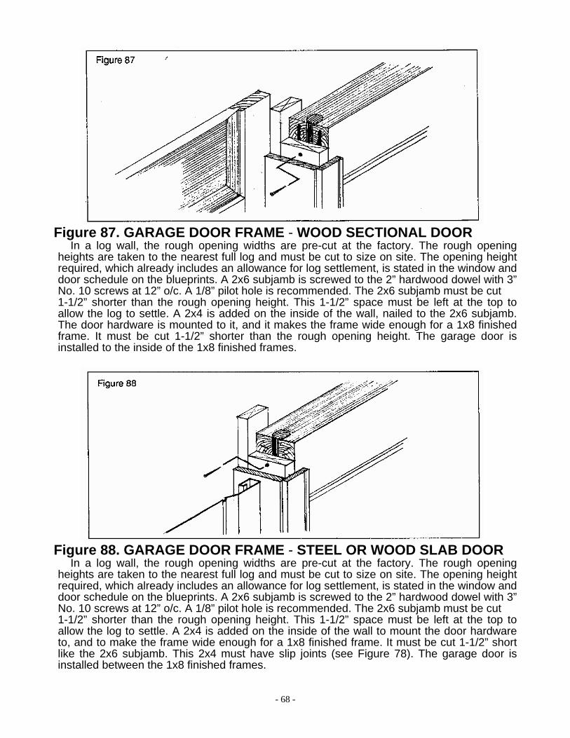
Figure 87. GARAGE DOOR FRAME - WOOD SECTIONAL DOOR In a log wall, the rough opening widths are pre-cut at the factory. The rough opening
heights are taken to the nearest full log and must be cut to size on site. The opening height required, which already includes an allowance for log settlement, is stated in the window and door schedule on the blueprints. A 2x6 subjamb is screwed to the 2” hardwood dowel with 3” No. 10 screws at 12” o/c. A 1/8” pilot hole is recommended. The 2x6 subjamb must be cut 1-1/2” shorter than the rough opening height. This 1-1/2” space must be left at the top to allow the log to settle. A 2x4 is added on the inside of the wall, nailed to the 2x6 subjamb. The door hardware is mounted to it, and it makes the frame wide enough for a 1x8 finished frame. It must be cut 1-1/2” shorter than the rough opening height. The garage door is installed to the inside of the 1x8 finished frames.
Figure 88. GARAGE DOOR FRAME - STEEL OR WOOD SLAB DOOR In a log wall, the rough opening widths are pre-cut at the factory. The rough opening
heights are taken to the nearest full log and must be cut to size on site. The opening height required, which already includes an allowance for log settlement, is stated in the window and door schedule on the blueprints. A 2x6 subjamb is screwed to the 2” hardwood dowel with 3” No. 10 screws at 12” o/c. A 1/8” pilot hole is recommended. The 2x6 subjamb must be cut 1-1/2” shorter than the rough opening height. This 1-1/2” space must be left at the top to allow the log to settle. A 2x4 is added on the inside of the wall to mount the door hardware to, and to make the frame wide enough for a 1x8 finished frame. It must be cut 1-1/2” short like the 2x6 subjamb. This 2x4 must have slip joints (see Figure 78). The garage door is installed between the 1x8 finished frames.
- 69 -
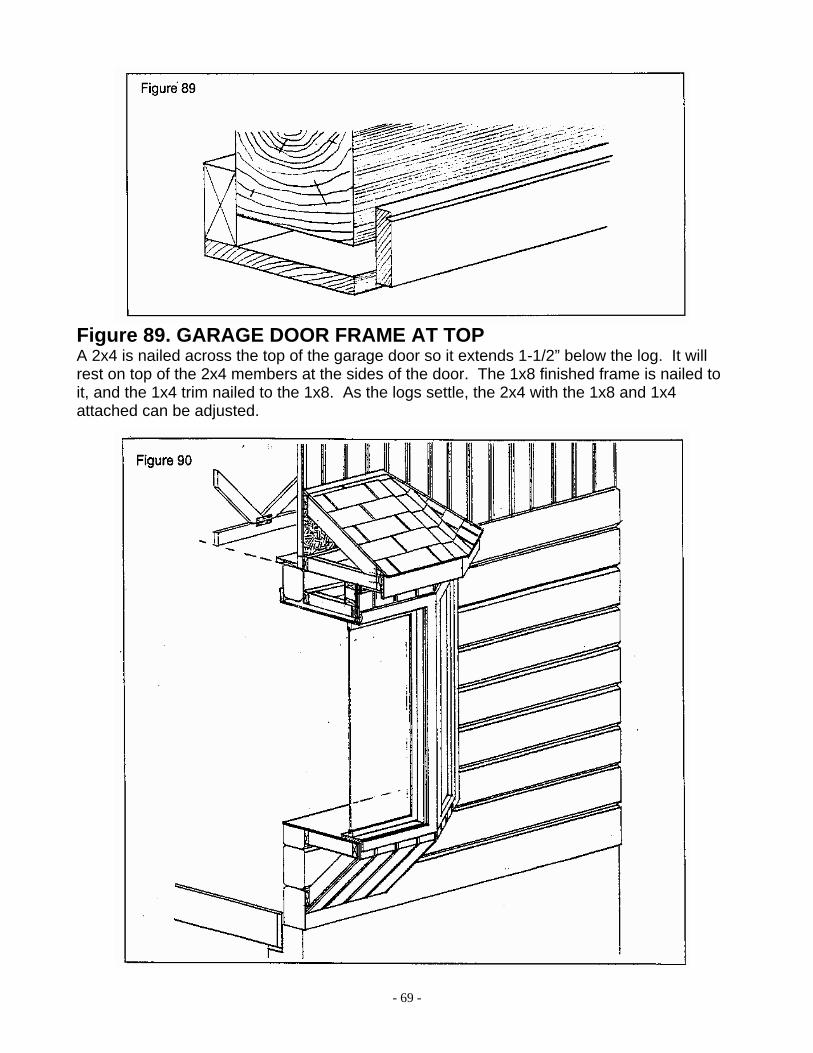
Figure 89. GARAGE DOOR FRAME AT TOP A 2x4 is nailed across the top of the garage door so it extends 1-1/2” below the log. It will rest on top of the 2x4 members at the sides of the door. The 1x8 finished frame is nailed to it, and the 1x4 trim nailed to the 1x8. As the logs settle, the 2x4 with the 1x8 and 1x4 attached can be adjusted.

- 70 -
Figure 90. BAY WINDOWS
The sub jamb should be installed as per Figure 85. If the bay is a walk-out unit, it will be built atop cantilevered floor joists, (see Figure 18). A stud wall is built atop the floor to the required height. The bay unit is then set atop this wall, and the headers installed. The height of the unit should be 1-1/2” lower than the top of the log wall. The unit can be secured to the subjambs. The size of the window headers will be noted either on the blueprints or on the material list. Aspenite, air barrier, and siding can then be installed.
If the bay unit has a seat, as the one illustrated, 2x4 framing and nailers are used to build the seat framing, which is spiked directly to the log wall. The log opening height may have to be cut on site. Plywood is used to finish the interior seat. The bay unit is then set atop the seat, and the headers installed. The height of the unit should be 1-1/2” lower than the top of the log wall. The exterior of the unit is then finished with aspenite, air barrier, and siding.
If the bay unit has a roof, as the one illustrated, 2x4 framing and nailers are used to build the roof framing. A 2x6 subfascia helps tie the framing together. The roof is attached to the house wall by nailing through the 2x4 nailers. It must be set 1-1/2” above the bay wall unit, to allow for settlement. Plywood and shingles can then be installed. See Figure 75e for step flashing installation during shingling. Wall-to-roof flashing (Figure 75c), must be installed across the top of the unit before the main house siding is installed. The soffit is then installed, and the 1-1/2” space covered with a piece of 1x4 trim.
If the bay unit is built under an eave, a 1-1/2” space must be left between the top of the unit and the soffit of the main structure. This space can be covered with a piece of 1x4 trim.
The walls, ceiling, and seat or floor must be insulated.
Figure 91. DRYWALL Drywall is a common finish for interior walls and ceilings. On walls, applying the sheets
horizontally reduces the amount of screws required. On ceilings, the sheets are usually applied at right angles to the framing members. The sheets can be held in position with a couple of blue nails, and then fastened with drywall screws. Corner bead should be used at external corners to protect them from damage.
The first layer of compound is applied on the joint. Drywall tape is then embedded into the compound with a trowel or knife. Excess compound should be removed. After the compound has dried, it should be sanded smooth. Take care so as not to damage the drywall paper.
The second layer of compound is then applied over the first layer and feathered to zero thickness. After it has dried, it should be sanded smooth.
The third layer of compound is then applied in the same manner. After it has dried, it should be sanded smooth.
The recessed screw heads are filled with one or two layers of compound and sanded smooth.

- 71 -
Figure 92. CORNICE TRIM
In a log building, a 1-1/2” allowance for log settlement must be left over the single top plate of the partitions. The partitions are held in place by 6” Hex Head Screw at 6 feet o/c, driven up through a pre-drilled hole in the top plate into 2x4 nailers or the ceiling members. The cornice moulding is nailed to the ceiling finish only. When the house settles, the moulding will slide down the surface of the wall.
Figure 93. INTERIOR CORNER TRIM
Apply a bead of caulking at the inside corners, It can be hidden by a piece of cove moulding. Plane the back of the cove so it can seat properly over the bead of caulking.

- 72 -
Figure 94. 1 x 6 TONGUE AND GROOVE FLOORING
1x6 tongue and groove flooring should be stored inside the heated and climatized structure for several weeks (6 weeks minimum) until it is climatized before installation. It comes in random lengths and is applied directly over the plywood subfloor. Make sure all end butt joints are square. The first strip of flooring can be nailed from the top since the nail will be covered by the baseboard trim. Nails should be driven through the tongue at a 45-degree angle as well. A nail set should be used to finish driving the nails so as not to damage the flooring with the hammer. The next strip of flooring is then brought tight against the first using a hammer and scrap piece of flooring. It is then nailed through the tongue as above. Staggering the end butt joints in the strips of flooring creates a stronger, better-looking floor.
1 x 6 TONGUE AND GROOVE CEILING (not illustrated) If decorative beams are used, see Figure 100 before installing the tongue and groove
ceiling. 1x6 tongue and groove should be stored inside the heated structure for several weeks (6 weeks minimum) until it is climatized before installing it. It comes in random lengths and is applied to the ceiling members. All end butt joints should be square, and fall over a ceiling member. The first strip of lumber can be nailed through the face since the nail will be covered by the cornice trim. Nails should be driven through the tongue at a 45-degree angle as well. A nail set should be used to finish driving the nail so as not to damage the lumber with the hammer. The next strip is then brought tight against the first using a hammer and scrap piece of tongue and groove. It is then nailed through the tongue as above. Staggering the end joints in the strips creates a better-looking ceiling.
Figure 95. DECK — STANDARD When the deck comes in to a concrete wall, as illustrated, lag bolts at 4 feet o/c with
shields and washers are used to attach the pressure treated box end joist. If it comes into a log or frame wall, 3” lag screws are used. Usually 2x8 pressure treated joists at 24” o/c are used. Blueprints and material list should be referred to. The joists are hangered to the box end joist, and are supported by a 3-or 4-ply 2x8 pressure treated beam. The outer pressure treated box end joist is then nailed to the joists. If a railing is to be built, the 4x4 pressure treated rail supports are set along side a joist and nailed in place. The 2x6 pressure treated decking is applied with the end butt joints staggered, and a 1/8” space between rows.

- 73 -
DECK - CANTILEVERED (not illustrated)
When a cantilevered deck is used, the floor joists extending into the house are pressure treated. The joist size and spacing will be specified on the blueprints. The outer pressure treated box end joist is then nailed to the joists. If a railing is to be built, the 4x4 pressure treated rail supports (at 4’-0” o/c max.) are set along side a joist and nailed in place. The 2x6 pressure treated decking is applied with end butt joints staggered and a 1/8” space between rows. If a door exits to the deck, a plate (i.e. 2x6) must be placed below the frame to raise the unit above the exterior 2x6 decking.
RAILING
The 2x4 pressure treated rail supports are attached to the 4x4 rail supports. The space between the bottom rail support and the 2x6 decking must not exceed 4”. A 2x6 pressure treated top rail is then installed. The 2x2 pressure treated pickets are nailed to the 2x4 rail supports at 5-1/2” o/c.
NOTE: Steps and support posts are not included.

- 74 -
Figure 96. GINGERBREAD AT PORCH POST
Decorative gingerbread can be installed between the porch post and the soffit (or porch beam),or between the log wall and the soffit (or porch beam). Drilling a pilot hole through the gingerbread and attaching it with screws is recommended so as not to split or damage the wood.
Figure 97. SCREWJACK AT PORCH POST (SIMILAR TO INTERIOR)
The screwjack can sit either on top of the deck and be covered with trim (as in Figure 56), or it can sit on top of the beam below the deck. If no deck exists, the piers must be solid or filled with concrete. A hole is drilled in the bottom of the post to allow for the threaded portion of the screwjack during adjustment. The lower plate is to be nailed to the deck or beam, (or lagged to the concrete pier), and the upper plate is nailed to the post.

- 75 -
Figure 98. FINIAL POSTS The back of the finial post must be notched 1” so it can fit over the subfascia. The finial is
attached to the subfascia with finishing nails.
GINGERBREAD AT GABLES The gingerbread will be pre-cut to fit the required roof pitch. The top pieces butt to the
finial post, or to each other if no finial is used. They are toe nailed through the back, to the finished fascia. Pilot holes are recommended. If desired, a metal plate can be used on the back of the gingerbread to attach it to the fascia.
ROSETTES Decorative rosettes can be installed at the top corners of windows and doors. Pilot holes
are recommended for the finishing nails.

- 76 -
Figure 99. BEAM TRUSS Beam trusses are usually constructed of 6 x 6 material. The pieces must be cut to the
proper length on the jobsite. A pocket must be created in the soffit to which the members of the beam truss can be nailed. The bottom chord and the vertical member will be notched, and can be spiked together from behind. The diagonal members must be angle-cut to fit between the bottom and vertical chords. They can be held in place with spikes.
Figure 100. DECORATIVE BEAMS
2x4 blocking should be securely nailed between the ceiling members at 24” o/c. Usually the ceiling is installed after the beams are up. A piece of vapour barrier is draped over the beam to both protect the beam while the ceiling is being finished, and to provide a continuation of the vapour barrier over the beam if the ceiling is insulated. The beam is nailed from the top, through the blocking, with three 3-1/2” ardox spikes. The ceiling finish can butt into the beam and be trimmed if desired. For the finished ceiling to be installed before the beams are put up, you must lag bolt up through the beam into the blocking. If the latter is used, the location of the blocking must be marked as the ceiling is being installed.

- 77 -
Figure 101. DECORATIVE SHUTTERS Decorative shutters are available in a patterned style or a standard style. They are nailed
in place with finishing nails.
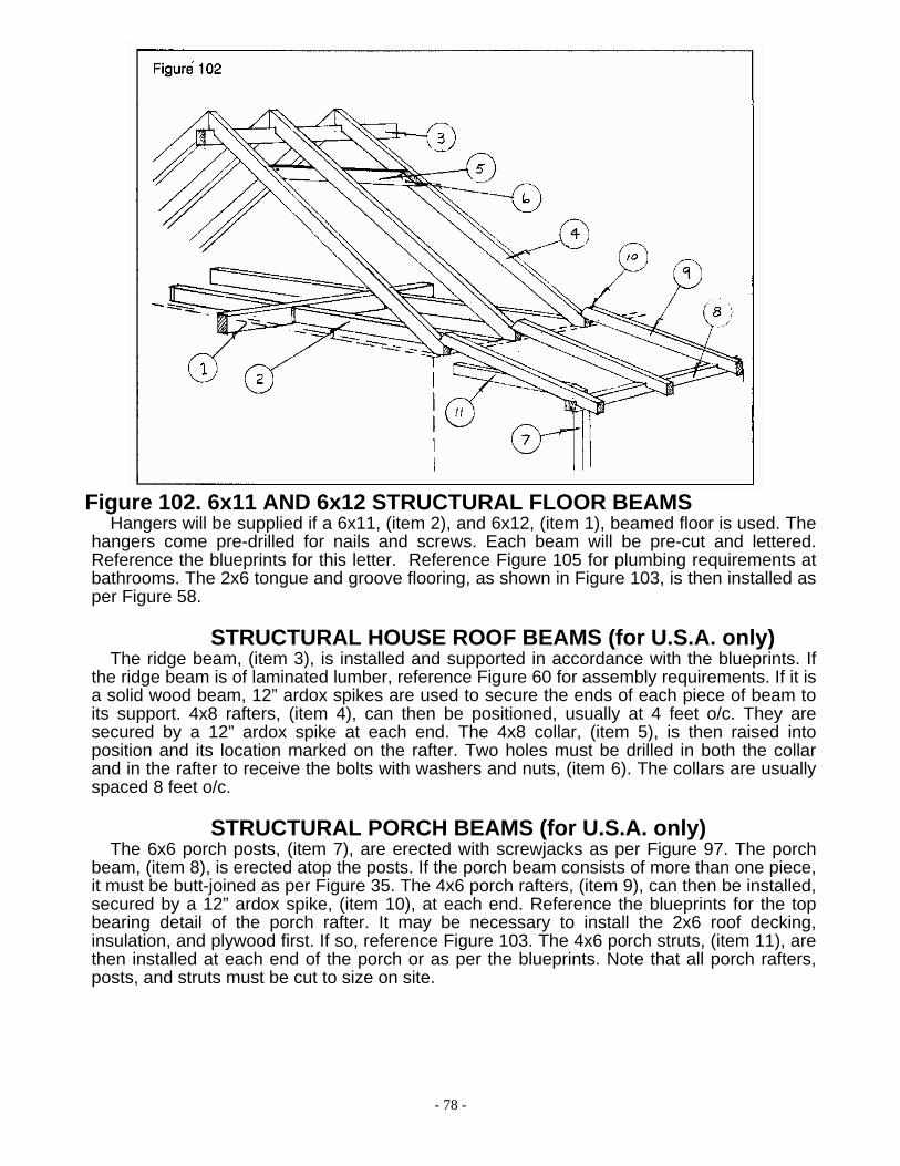
- 78 -
Figure 102. 6x11 AND 6x12 STRUCTURAL FLOOR BEAMS Hangers will be supplied if a 6x11, (item 2), and 6x12, (item 1), beamed floor is used. The
hangers come pre-drilled for nails and screws. Each beam will be pre-cut and lettered. Reference the blueprints for this letter. Reference Figure 105 for plumbing requirements at bathrooms. The 2x6 tongue and groove flooring, as shown in Figure 103, is then installed as per Figure 58.
STRUCTURAL HOUSE ROOF BEAMS (for U.S.A. only)
The ridge beam, (item 3), is installed and supported in accordance with the blueprints. If the ridge beam is of laminated lumber, reference Figure 60 for assembly requirements. If it is a solid wood beam, 12” ardox spikes are used to secure the ends of each piece of beam to its support. 4x8 rafters, (item 4), can then be positioned, usually at 4 feet o/c. They are secured by a 12” ardox spike at each end. The 4x8 collar, (item 5), is then raised into position and its location marked on the rafter. Two holes must be drilled in both the collar and in the rafter to receive the bolts with washers and nuts, (item 6). The collars are usually spaced 8 feet o/c.
STRUCTURAL PORCH BEAMS (for U.S.A. only) The 6x6 porch posts, (item 7), are erected with screwjacks as per Figure 97. The porch
beam, (item 8), is erected atop the posts. If the porch beam consists of more than one piece, it must be butt-joined as per Figure 35. The 4x6 porch rafters, (item 9), can then be installed, secured by a 12” ardox spike, (item 10), at each end. Reference the blueprints for the top bearing detail of the porch rafter. It may be necessary to install the 2x6 roof decking, insulation, and plywood first. If so, reference Figure 103. The 4x6 porch struts, (item 11), are then installed at each end of the porch or as per the blueprints. Note that all porch rafters, posts, and struts must be cut to size on site.

- 79 -
Figure 103. COMPLETING THE BEAMED FLOOR AND ROOF
(for U.S.A. only) The 2x6 tongue and groove flooring, (item 1), is installed as per Figure 58, before the roof
beams are erected as per Figure 102. 2x6 tongue and groove roof decking, (item 2), is then installed in the same manner as 2x6 flooring, but without the adhesive. The decking extends into the overhangs to create the finished soffit. Rigid insulation panels, (item 3), are then placed on top of the 2x6 decking. The insulation does not extend into the rake or eave overhangs or onto the porch. Blocking, (item 4), is installed at 24” o/c at all rake and eave overhangs to provide support for the plywood where there is no insulation. The subfascia, (item 5), is then nailed to the blocking. A subfascia is not required on the porch, for the fascia can be nailed directly to the rafters. The roof plywood, (item 6), is screwed with 7” panel fasteners, through the rigid insulation, into the 2x6 decking. The roof plywood is not used on the porch roof. Felt paper, (item 7), is then used over the entire roof, including the porch. The roof can then be shingled, (item 8), and the finished fascia, (item 9), installed.
NOTE: Subject to availability, the insulation panels and the roof plywood will be laminated
together for ease of installation.

- 80 -
Figure 104. KITCHEN CUPBOARDS
The upper cabinets can be screwed to the wall at the top of the vertical back braces. The bottom of the braces should be slotted to allow for the logs to settle behind the cupboards. A screw with a washer must be used to attach the bottom through the slot.
The top of the vertical back brace of the lower cabinets should be slotted in the same manner.
Figure 105. PLUMBING
In structures that have plumbing on the second floor, settlement allowances must be made on the waste stacks and the water pipes. Single storey structures do not require any settlement allowances in the plumbing. For the waste stack, a 1-1/2” section must be cut from the pipe. The two pieces must be joined by a rubber gasket and screw clamps at each end. As the house settles, one of the clamps can be loosened and adjusted. For the water pipes, a copper or plastic coil should be used. A plumber should be consulted for the proper materials required for these applications.
BATHROOMS WITH STRUCTURAL BEAMS (not illustrated) Since the waste pipe from a toilet is usually hidden in the floor, a problem arises when
structural beams and 2x6 tongue and groove flooring are used. One of three methods can be used to hide the waste pipe. The best method is to have the pipe line up with a partition below. If this is not possible, the pipe can be boxed-in from below. This is okay if the boxed-in pipe is in a closet, bathroom, or other room where its appearance is not undesirable. The third method is to build a raised floor under the toilet. The height required will depend on how far the waste pipe must travel to reach a partition below.

- 81 -
Figure 106. NAIL TYPES AND USES 1. 6” COMMON OR ARDOX SPIKE Use: secure partitions at 6 feet o/c in a log structure. 6” Hex Head Screws can also be used.
2. 3/8” x 7” LAG SCREW Use: attaching steel flatbar to logs.
3. 3-1/2” ARDOX SPIKE 3-1/2” HOT GALVANIZED ARDOX SPIKE Use: joists, beams, rafters, and studs. Use: 2x12 exterior siding, and decks. 4. 2-1/2” ARDOX SPIKE Use: floor and roof plywood, and aspenite.
5. 1-1/2” GALVANIZED ARDOX FINISHING NAIL Use: Hot Galvanized – 1x6 soffits. Use: Electro Galvanized – 1x6 ceilings and 1x6 floors
6. 1-1/4” ELECTRO GALVANIZED ROOFING NAIL Use: shingles.
7. 2-1/2” HOT GALVANIZED ARDOX OVAL HEAD NAIL Use: 1x8 siding, trim, fascia, and deck rail pickets.
8. 3” No. 10 WOOD SCREW Use: install subjambs to dowels at windows and doors.
9. 3-1/2” ELECTRO GALVANIZED ARDOX FINISHING NAIL Use: 2x6 T&G flooring, and interior 2x12 siding.
10. 1-1/2” COMMON JOIST HANGER NAIL Use: TJI floor joists hangers, TJI roof rafter hangers, ridge straps.
11. 3” HOT GALVANIZED COMMON NAIL Use: TJI joists (including nailing doubles together), TJI roof rafters & TJI roof rafter hangers.

- 82 -
CARE AND MAINTENANCE OF YOUR LOG HOME
CLEANING
Some logs may be sun faded more than others. In this case, bleaching of the logs is suggested. Bleaching is a procedure of spraying or brushing a mixture of 50% bleach and 50% water onto the log wall. Start at the bottom log and scrub horizontally to the top log. Allow to sit for approximately one hour before rinsing with water. Re-apply bleaching if necessary to darker areas. This procedure may be applied to both the inside and the outside of the log wall.
CAULKING Before each winter, check around windows, doors, logs, dovetails, and thru-bolt holes to
ensure air-tight seals. Caulk as required.
SETTLEMENT Thru-bolts should be tightened once every week during the first couple of months of
construction prior to trimming. They should then be checked yearly. Teleposts and screwjacks should be checked when thru-bolts are tightened, then checked yearly. Second floor waste stacks, kitchen cupboards, and garage door frames should be checked yearly. If the logs have settled, it will be necessary to make the required adjustments.
LOG CHECKS Any type of wood will check to some degree. Usually the larger the log, or piece of wood,
the larger the check. Checking is a crack in the log that runs parallel to the grain. Checking usually occurs during the first year.
Log checking may be reduced by staining the logs, (mentioned below), and by using a humidifier. If possible, maintain humidity over 40% for the first year to keep the logs from drying too quickly.
STAINING Staining will help reduce the amount a log will check. A quality stain will slow down the
drying process, and at the same time, protect the logs. Stain should be applied with a brush to penetrate into the checks.
Stains should be applied as follows:
Exterior As per stain manufacturers recommendations, clean logs thoroughly, allow to dry. Apply 1
coat Cetol 1, after 24 hrs. apply second coat of Cetol 1, after 24 hrs. apply 1 coat Cetol 23 plus.
Interior As per the stain manufacturer’s recommendations, clean logs thoroughly, allow to dry,
sand if necessary. Apply 1 coat Cetol TS Interior, after 24 hrs. sand and vacuum and apply 1 coat Cetol TS Interior. If desired an optional third coat should be applied.
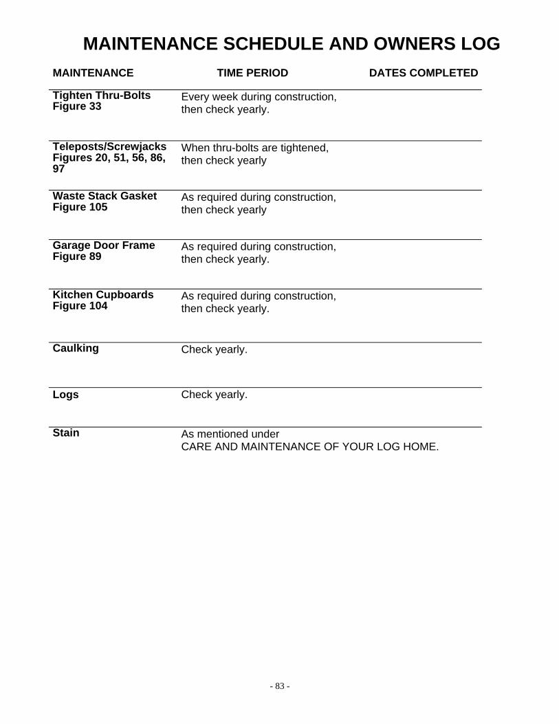
- 83 -
MAINTENANCE SCHEDULE AND OWNERS LOG MAINTENANCE TIME PERIOD DATES COMPLETED Tighten Thru-Bolts Figure 33
Every week during construction, then check yearly.
Teleposts/Screwjacks Figures 20, 51, 56, 86, 97
When thru-bolts are tightened, then check yearly
Waste Stack Gasket Figure 105
As required during construction, then check yearly
Garage Door Frame Figure 89
As required during construction, then check yearly.
Kitchen Cupboards Figure 104
As required during construction, then check yearly.
Caulking
Check yearly.
Logs Check yearly.
Stain As mentioned under CARE AND MAINTENANCE OF YOUR LOG HOME.
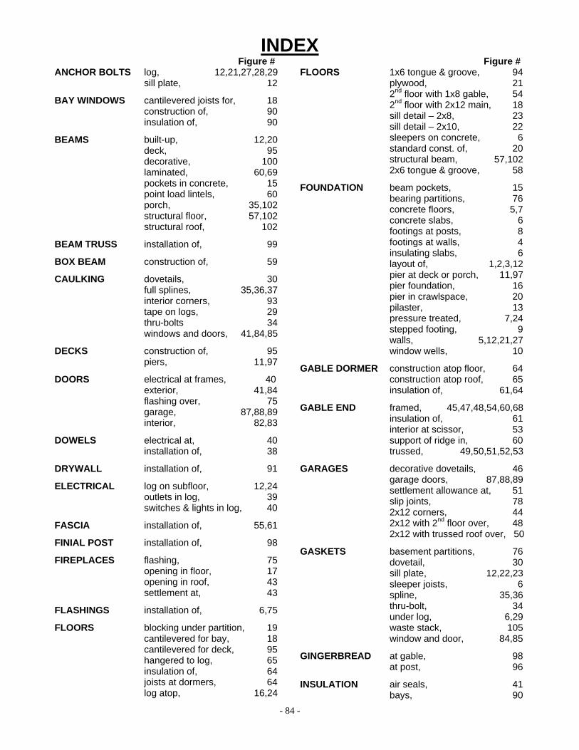
- 84 -
INDEX Figure # ANCHOR BOLTS log, 12,21,27,28,29 sill plate, 12
BAY WINDOWS cantilevered joists for, 18 construction of, 90 insulation of, 90
BEAMS built-up, 12,20 deck, 95 decorative, 100 laminated, 60,69 pockets in concrete, 15 point load lintels, 60 porch, 35,102 structural floor, 57,102 structural roof, 102
BEAM TRUSS installation of, 99
BOX BEAM construction of, 59
CAULKING dovetails, 30 full splines, 35,36,37 interior corners, 93 tape on logs, 29
thru-bolts 34 windows and doors, 41,84,85
DECKS construction of, 95 piers, 11,97
DOORS electrical at frames, 40 exterior, 41,84 flashing over, 75 garage, 87,88,89 interior, 82,83
DOWELS electrical at, 40 installation of, 38
DRYWALL installation of, 91
ELECTRICAL log on subfloor, 12,24 outlets in log, 39 switches & lights in log, 40
FASCIA installation of, 55,61
FINIAL POST installation of, 98
FIREPLACES flashing, 75 opening in floor, 17 opening in roof, 43 settlement at, 43
FLASHINGS installation of, 6,75
FLOORS blocking under partition, 19 cantilevered for bay, 18 cantilevered for deck, 95 hangered to log, 65 insulation of, 64 joists at dormers, 64 log atop, 16,24
Figure # FLOORS 1x6 tongue & groove, 94 plywood, 21 2nd floor with 1x8 gable, 54 2nd floor with 2x12 main, 18 sill detail – 2x8, 23 sill detail – 2x10, 22 sleepers on concrete, 6 standard const. of, 20 structural beam, 57,102 2x6 tongue & groove, 58
FOUNDATION beam pockets, 15 bearing partitions, 76 concrete floors, 5,7 concrete slabs, 6 footings at posts, 8 footings at walls, 4 insulating slabs, 6 layout of, 1,2,3,12 pier at deck or porch, 11,97 pier foundation, 16 pier in crawlspace, 20 pilaster, 13 pressure treated, 7,24 stepped footing, 9 walls, 5,12,21,27 window wells, 10
GABLE DORMER construction atop floor, 64 construction atop roof, 65 insulation of, 61,64
GABLE END framed, 45,47,48,54,60,68 insulation of, 61 interior at scissor, 53 support of ridge in, 60 trussed, 49,50,51,52,53
GARAGES decorative dovetails, 46 garage doors, 87,88,89 settlement allowance at, 51 slip joints, 78 2x12 corners, 44 2x12 with 2nd floor over, 48 2x12 with trussed roof over, 50
GASKETS basement partitions, 76 dovetail, 30 sill plate, 12,22,23 sleeper joists, 6 spline, 35,36 thru-bolt, 34 under log, 6,29 waste stack, 105 window and door, 84,85
GINGERBREAD at gable, 98 at post, 96
INSULATION air seals, 41 bays, 90
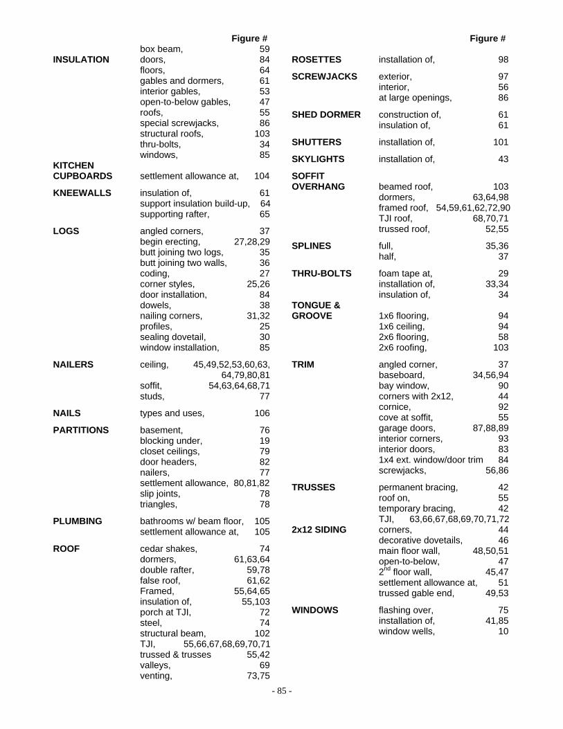
- 85 -
Figure # box beam, 59 INSULATION doors, 84 floors, 64 gables and dormers, 61 interior gables, 53 open-to-below gables, 47 roofs, 55 special screwjacks, 86 structural roofs, 103 thru-bolts, 34 windows, 85 KITCHEN CUPBOARDS settlement allowance at, 104
KNEEWALLS insulation of, 61 support insulation build-up, 64 supporting rafter, 65
LOGS angled corners, 37 begin erecting, 27,28,29 butt joining two logs, 35 butt joining two walls, 36 coding, 27 corner styles, 25,26 door installation, 84 dowels, 38 nailing corners, 31,32 profiles, 25 sealing dovetail, 30 window installation, 85
NAILERS ceiling, 45,49,52,53,60,63, 64,79,80,81 soffit, 54,63,64,68,71 studs, 77
NAILS types and uses, 106
PARTITIONS basement, 76 blocking under, 19 closet ceilings, 79 door headers, 82 nailers, 77 settlement allowance, 80,81,82 slip joints, 78 triangles, 78
PLUMBING bathrooms w/ beam floor, 105 settlement allowance at, 105
ROOF cedar shakes, 74 dormers, 61,63,64 double rafter, 59,78 false roof, 61,62 Framed, 55,64,65 insulation of, 55,103 porch at TJI, 72 steel, 74 structural beam, 102 TJI, 55,66,67,68,69,70,71 trussed & trusses 55,42 valleys, 69 venting, 73,75
Figure #
ROSETTES installation of, 98
SCREWJACKS exterior, 97 interior, 56 at large openings, 86
SHED DORMER construction of, 61 insulation of, 61
SHUTTERS installation of, 101
SKYLIGHTS installation of, 43
SOFFIT OVERHANG beamed roof, 103 dormers, 63,64,98 framed roof, 54,59,61,62,72,90 TJI roof, 68,70,71 trussed roof, 52,55
SPLINES full, 35,36 half, 37
THRU-BOLTS foam tape at, 29 installation of, 33,34 insulation of, 34 TONGUE & GROOVE 1x6 flooring, 94 1x6 ceiling, 94 2x6 flooring, 58 2x6 roofing, 103
TRIM angled corner, 37 baseboard, 34,56,94 bay window, 90 corners with 2x12, 44 cornice, 92 cove at soffit, 55 garage doors, 87,88,89 interior corners, 93 interior doors, 83 1x4 ext. window/door trim 84 screwjacks, 56,86
TRUSSES permanent bracing, 42 roof on, 55 temporary bracing, 42 TJI, 63,66,67,68,69,70,71,72
2x12 SIDING corners, 44 decorative dovetails, 46 main floor wall, 48,50,51 open-to-below, 47 2nd floor wall, 45,47 settlement allowance at, 51 trussed gable end, 49,53
WINDOWS flashing over, 75 installation of, 41,85 window wells, 10