1856-30 2007 summer college on plasma...
TRANSCRIPT

1856-30
2007 Summer College on Plasma Physics
M. E. Dieckmann
30 July - 24 August, 2007
Institut fuer Theoretische Physik IV,Ruhr-Universitaet,Bochum, Germany
The particle-in-cell simulation method: Concept and limitations

The particle-in-cellsimulation method:
Concept and limitations
Mark Eric Dieckmann
Why (and when)particle-in-cell (PIC)simulations?
What do PIC / Vlasovcodes solve?
Numerics / Principle
Phase space distribution
Particle-grid interaction
Assignment scheme:Particles ↔ Grid
PIC algorithm
Limitations
Spatial grid effects
Finite grid instability
PIC simulation
Discussion
p. 1
The particle-in-cell simulation method: Concept
and limitations
Mark Eric Dieckmann
Institut fur Theoretische Physik IVRuhr-Universitat BochumD-44780 Bochum
Institutionen for teknik och naturvetenskap (ITN)Linkopings universitetCampus NorrkopingSE-60174 Norrkoping
Book: C K Birdsall & A B Langdon, Plasma Physics Via Computer Simulation,Taylor & Francis Ltd (October 2004)

Contents
1. Why (and when) particle-in-cell (PIC) simulations?
2. What do PIC / Vlasov codes solve?
3. Numerics / Principle
4. Phase space distribution
5. Particle-grid interaction
6. Assignment scheme: Particles ↔ Grid
7. PIC algorithm
8. Limitations
9. Spatial grid effects
10. Finite grid instability
11. PIC simulation
12. Discussion

The particle-in-cellsimulation method:
Concept and limitations
Mark Eric Dieckmann
Why (and when)particle-in-cell (PIC)simulations?
What do PIC / Vlasovcodes solve?
Numerics / Principle
Phase space distribution
Particle-grid interaction
Assignment scheme:Particles ↔ Grid
PIC algorithm
Limitations
Spatial grid effects
Finite grid instability
PIC simulation
Discussion
p. 3
Why (and when) particle-in-cell (PIC) simulations?
• Particle-in-cell / Vlasov codes can address all collisionless plasma processes
• Such codes can be used to verify linearized plasma dispersion relations
• The plasma dynamics can be followed through its non-linear phase
• PIC simulations have an ’unlimited’ dynamical range for the particle ve-locities and no boundary conditions along v
• PIC codes have a limited signal-to-noise ratio and phase space densityresolution
• PIC schemes parallelize well

The particle-in-cellsimulation method:
Concept and limitations
Mark Eric Dieckmann
Why (and when)particle-in-cell (PIC)simulations?
What do PIC / Vlasovcodes solve?
Numerics / Principle
Phase space distribution
Particle-grid interaction
Assignment scheme:Particles ↔ Grid
PIC algorithm
Limitations
Spatial grid effects
Finite grid instability
PIC simulation
Discussion
p. 4
What do PIC / Vlasov codes solve?
∇× E = −∂B
∂t(1)
∇× B = µ0ε0∂E
∂t+ µ0J (2)
∇ · B = 0 (3)
∇ ·E = ρ/ε0 (4)
Vlasov equation for phase space distribution f(x,v, t)
∂f
∂t+ v · ∇xf +
q
m(E + v × B) · ∇vf = 0 (5)
ρ(x, t) = q
∫∞
−∞
f(x,v, t) dv, J(x,v, t) = q
∫∞
−∞
vf(x,v, t) dv (6)

The particle-in-cellsimulation method:
Concept and limitations
Mark Eric Dieckmann
Why (and when)particle-in-cell (PIC)simulations?
What do PIC / Vlasovcodes solve?
Numerics / Principle
Phase space distribution
Particle-grid interaction
Assignment scheme:Particles ↔ Grid
PIC algorithm
Limitations
Spatial grid effects
Finite grid instability
PIC simulation
Discussion
p. 5
Numerics / Principle
Field equations
Replace continuous fields B(x, t), E(x, t) and Maxwell’s equations by their dis-cretized counterparts.
(1) Introduce finite spatial resolution x → j∆x and finite time resolution t →j∆t, with integer values j.
(2) Replace differential operators by difference operators.Example: d
dxf(x) → (f [(j + 1)∆x] − f [j∆x])/∆x.
⇒ Replaces differential equations by algebraic equations.
Particle equations (PIC codes only)
Replace continuous probability distribution by phase space elements
f(x,v, t) ⇒N∑
i=1
S(x − xi)δ(v − vi), (7)
where S(x) is a shape function, e.g. a triangle.
⇒ Replaces phase space probability function by ’computational particles’.

The particle-in-cellsimulation method:
Concept and limitations
Mark Eric Dieckmann
Why (and when)particle-in-cell (PIC)simulations?
What do PIC / Vlasovcodes solve?
Numerics / Principle
Phase space distribution
Particle-grid interaction
Assignment scheme:Particles ↔ Grid
PIC algorithm
Limitations
Spatial grid effects
Finite grid instability
PIC simulation
Discussion
p. 6
Phase space distribution: Maxwellian distributions are often used.
Quantitatively different results are sometimes obtained with Vlasov codes (upperphase space distribution) and PIC codes (lower phase space distribution)!
• If particle weights are equal, the statistical representation of the plasmaclose to the mean speed of the species is good.
• The statistical representation is poor, if |v − v| ≥ 2vt for a Maxwellian
exp (−(v − v)2/ 2 v2
t ).

The particle-in-cellsimulation method:
Concept and limitations
Mark Eric Dieckmann
Why (and when)particle-in-cell (PIC)simulations?
What do PIC / Vlasovcodes solve?
Numerics / Principle
Phase space distribution
Particle-grid interaction
Assignment scheme:Particles ↔ Grid
PIC algorithm
Limitations
Spatial grid effects
Finite grid instability
PIC simulation
Discussion
p. 7
Particle-grid interaction
X X X Xi i+1 i+2 i+3
FieldNode
FieldNode
Particles
• The fields are defined on a grid (Field nodes).
• The particles move on ’continuous’ paths.
• Particles interact with the grid through ρ and J.
• The grid interacts with the particles through E and B.
⇒ Interpolation schemes must be specified

The particle-in-cellsimulation method:
Concept and limitations
Mark Eric Dieckmann
Why (and when)particle-in-cell (PIC)simulations?
What do PIC / Vlasovcodes solve?
Numerics / Principle
Phase space distribution
Particle-grid interaction
Assignment scheme:Particles ↔ Grid
PIC algorithm
Limitations
Spatial grid effects
Finite grid instability
PIC simulation
Discussion
p. 8
• A computational electron is located between the cells i, i + 1 with thepositions Xi and Xi+1.
• It has the distance D1 from Xi and D2 from Xi+1.
• Electron charge Q is assigned to the grid nodes i, i + 1:
Ci = f1(D1, D2) and Ci+1 = f2(D1, D2).
• Example: Ci = Q D2 and Ci+1 = Q D1 if (Xi+1 − Xi) = 1.
CI C I+1
X XX
D1 D2
C CI I+1
i i+1
Electric field E
EElectron
Electron
Force
• Calculate potential Φ with ∇2Φ = −ρ/ε0 with ρi ∼ Ci and ρi+1 ∼ Ci+1.
• E = −∇Φ.
• Interpolate E to particle position: E(x) = D2 · E(xi) + D1 ·E(xi+1)

The particle-in-cellsimulation method:
Concept and limitations
Mark Eric Dieckmann
Why (and when)particle-in-cell (PIC)simulations?
What do PIC / Vlasovcodes solve?
Numerics / Principle
Phase space distribution
Particle-grid interaction
Assignment scheme:Particles ↔ Grid
PIC algorithm
Limitations
Spatial grid effects
Finite grid instability
PIC simulation
Discussion
p. 9
1. Initialize plasma phase space distribution:
− Place particles in space according to density
− Initialize velocities with random numbers
2. Initialize E and B fields
3. From E,B fields calculate acceleration
4. Multiply acceleration with time step
−> Velocity increment
−> Position increment
6. From new positions and velocities:
Calculate new E,B
5. Multiply velocity with time step

The particle-in-cellsimulation method:
Concept and limitations
Mark Eric Dieckmann
Why (and when)particle-in-cell (PIC)simulations?
What do PIC / Vlasovcodes solve?
Numerics / Principle
Phase space distribution
Particle-grid interaction
Assignment scheme:Particles ↔ Grid
PIC algorithm
Limitations
Spatial grid effects
Finite grid instability
PIC simulation
Discussion
p. 10
Limitations:
Known limitations with known consequence: Field discretization
• Spatial step ∆x ≈ Debye length λd = vt/ωp.
• Numerical stability → small time step ∆t.For my code: ∆t = Nc∆x/
√2 c with 0 < Nc < 1.
• We have ∆x = vt/ωp and for Nc = 1 we get√
2∆tωp = vt/c.⇒ Low vt requires high sampling rate. Critical speed vt ≈ 106m/s.
Known limitations with unknown consequence:
Particle per cell count rates follow Poisson statistics → For Ne particles per cell,the relative fluctuations are 1/
√Ne.
• Fluctuations result in particle-wave collisions.
• Parametric instabilities speed up.
• Dispersive properties change. Bernstein modes are damped ’close’ to nωc.
• Signal-to-noise ratio is low.

The particle-in-cellsimulation method:
Concept and limitations
Mark Eric Dieckmann
Why (and when)particle-in-cell (PIC)simulations?
What do PIC / Vlasovcodes solve?
Numerics / Principle
Phase space distribution
Particle-grid interaction
Assignment scheme:Particles ↔ Grid
PIC algorithm
Limitations
Spatial grid effects
Finite grid instability
PIC simulation
Discussion
p. 11
Spatial grid effects
In ’continuous infinite plasmas’: Fourier integral
Infinitely extended and continuous position x and wavenumber k domains.
f(x) ⇔ g(k) (8)
f(x) =
∫∞
−∞
g(k) exp (ıkx) dk (9)
g(k) =1
2π
∫∞
−∞
f(x) exp (−ıkx) dx (10)
0 0.2 0.4 0.6 0.8 10
0.5
1
Position
Am
plitu
de
−1 −0.5 0 0.5 1
100
Wavenumber
Pow
er

The particle-in-cellsimulation method:
Concept and limitations
Mark Eric Dieckmann
Why (and when)particle-in-cell (PIC)simulations?
What do PIC / Vlasovcodes solve?
Numerics / Principle
Phase space distribution
Particle-grid interaction
Assignment scheme:Particles ↔ Grid
PIC algorithm
Limitations
Spatial grid effects
Finite grid instability
PIC simulation
Discussion
p. 12
In ’continuous confined plasmas’: Fourier series
Limited position 0 < x < L, f(x) continuous. Unlimited, discrete k spectrum.
f(x) ⇔ gk = g(kk) (11)
f(x) =
∞∑k=−∞
gk exp (ı kk x) (12)
gk =1
L
∫ x=L
x=0
f(x) exp (−ı kk x) dx (13)
Periodicity of exp (ı ki x) → The f(x) is periodic, but not gi.
0 0.5 1 1.5 2 2.5 30
0.5
1
Position
Am
plitu
de
−1 −0.5 0 0.5 1
100
Wavenumber
Pow
er

The particle-in-cellsimulation method:
Concept and limitations
Mark Eric Dieckmann
Why (and when)particle-in-cell (PIC)simulations?
What do PIC / Vlasovcodes solve?
Numerics / Principle
Phase space distribution
Particle-grid interaction
Assignment scheme:Particles ↔ Grid
PIC algorithm
Limitations
Spatial grid effects
Finite grid instability
PIC simulation
Discussion
p. 13
In ’PIC plasmas’: Discrete Fourier transform
The PIC code cannot represent a Fourier series → The k-spectrum is truncated.
fn = f(xn) ⇔ gk = g(kk) (14)
fn =
N−1∑k=0
gk exp (2πıkn/N), n = 0, ..., N − 1 (15)
gk =1
N
N−1∑n=0
fn exp (−2πıkn/N), k = 0, ..., N − 1 (16)
0 0.5 1 1.5 2 2.5 30
0.5
1
Position
Am
plitu
de
−1 0 1 2 3 4 5
100
Wavenumber
Pow
er

The particle-in-cellsimulation method:
Concept and limitations
Mark Eric Dieckmann
Why (and when)particle-in-cell (PIC)simulations?
What do PIC / Vlasovcodes solve?
Numerics / Principle
Phase space distribution
Particle-grid interaction
Assignment scheme:Particles ↔ Grid
PIC algorithm
Limitations
Spatial grid effects
Finite grid instability
PIC simulation
Discussion
p. 14
Finite grid instability
• Phase space distribution has rapid oscillations: F (ks, x) = sin (ksx) .
• Grid imposes a maximum kNy = π/∆x.
• A box with length L has the minimum kM = 2π/L.
(a) k1 = kNy/25 and k2 = kNy/100. Integer values for k1/kM and k2/kM .
0 100 200 300 400 500−1
−0.5
0
0.5
1
Position in ∆x
Am
plitu
de
0 0.01 0.02 0.03 0.04 0.05 0.06
10−10
100
k / kNy
Pow
er

The particle-in-cellsimulation method:
Concept and limitations
Mark Eric Dieckmann
Why (and when)particle-in-cell (PIC)simulations?
What do PIC / Vlasovcodes solve?
Numerics / Principle
Phase space distribution
Particle-grid interaction
Assignment scheme:Particles ↔ Grid
PIC algorithm
Limitations
Spatial grid effects
Finite grid instability
PIC simulation
Discussion
p. 15
(b) k1 = kNy/25.25 and k2 = kNy/100.25. Non-integer k1/kM and k2/kM .
0 100 200 300 400 500−1
−0.5
0
0.5
1
Position in ∆x
Am
plitu
de
0 0.01 0.02 0.03 0.04 0.05 0.06
10−10
100
k / kNy
Pow
er
Wave oscillation is well-resolved.
Finite-box effects ’fill up’ the k-spectrum: power leaks to other k (aliasing).
The particle-in-cellsimulation method:
Concept and limitations
Mark Eric Dieckmann
Why (and when)particle-in-cell (PIC)simulations?
What do PIC / Vlasovcodes solve?
Numerics / Principle
Phase space distribution
Particle-grid interaction
Assignment scheme:Particles ↔ Grid
PIC algorithm
Limitations
Spatial grid effects
Finite grid instability
PIC simulation
Discussion
p. 16
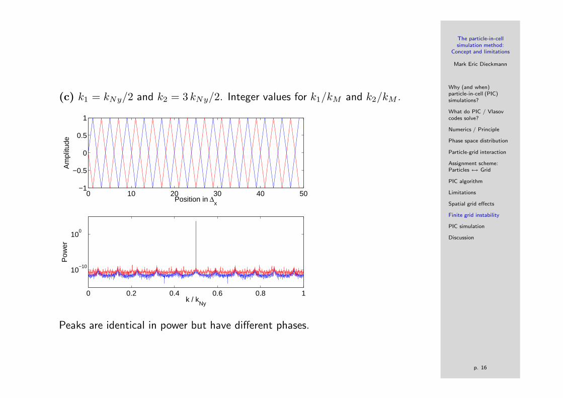
(c) k1 = kNy/2 and k2 = 3 kNy/2. Integer values for k1/kM and k2/kM .
0 10 20 30 40 50−1
−0.5
0
0.5
1
Position in ∆x
Am
plitu
de
0 0.2 0.4 0.6 0.8 1
10−10
100
k / kNy
Pow
er
Peaks are identical in power but have different phases.

The particle-in-cellsimulation method:
Concept and limitations
Mark Eric Dieckmann
Why (and when)particle-in-cell (PIC)simulations?
What do PIC / Vlasovcodes solve?
Numerics / Principle
Phase space distribution
Particle-grid interaction
Assignment scheme:Particles ↔ Grid
PIC algorithm
Limitations
Spatial grid effects
Finite grid instability
PIC simulation
Discussion
p. 17
Some consequences:
• The aliasing is introduced by mapping oscillations with an ’unlimited’k−spectrum onto a grid with |k| < kNy.
• Case (3) showed that k1, k2 with k1 − k2 = kNy differ only in phase.
• Truncated Fourier series → forced periodicity in x and k.
Signals with k1 and k2 differing by 2 kNy can’t be distinguished!
• Relation to crystals / metals: Brillouin zones
• First Brillouin zone |k∆x| < π. Other zones differ by 2 kNy = kg =2π/∆x.
• In PIC simulations, elementary sine waves are actually not (!) eigenfunc-tions of the system.

The particle-in-cellsimulation method:
Concept and limitations
Mark Eric Dieckmann
Why (and when)particle-in-cell (PIC)simulations?
What do PIC / Vlasovcodes solve?
Numerics / Principle
Phase space distribution
Particle-grid interaction
Assignment scheme:Particles ↔ Grid
PIC algorithm
Limitations
Spatial grid effects
Finite grid instability
PIC simulation
Discussion
p. 18
Finite grid instability
Counterstreaming two-stream instability
1 − ω2p
ω2=
Ω2b
(ω − kvb)2 +
Ω2b
(ω + kvb)2 (17)
• Physical resonance term: ω − kvb = 0
• Aliasing: ω − (k + pkg)vb = 0, with integer p.
• The term kgvb has the dimension of a frequency. It is the grid crossingfrequency ωg of the particle beam.
• The beam drives many resonances(ω−p ωg)
k= vb. Only p = 0 is physical.
• Consequence: In non-relativistic 1D simulations with k ‖ vb the nonphys-ical instabilities are electrostatic and only heat the beam → Harmless.

The particle-in-cellsimulation method:
Concept and limitations
Mark Eric Dieckmann
Why (and when)particle-in-cell (PIC)simulations?
What do PIC / Vlasovcodes solve?
Numerics / Principle
Phase space distribution
Particle-grid interaction
Assignment scheme:Particles ↔ Grid
PIC algorithm
Limitations
Spatial grid effects
Finite grid instability
PIC simulation
Discussion
p. 19
Finite grid instability of relativistic beams in 2D
• The phase speeds of the waves are ωk
= vb + pωg
k.
• For speeds 1 − ε < vb/c < 1 and ε 1, a p = 0 introduces superluminalwaves that couple directly to the beam. The resonance is sharp.
• Particle oscillations due to a wave with k ‖ vb couple through γ to othervelocity components.
Quiver motion acts as antenna!
• In 2D/3D simulations, obliquely propagating electromagnetic waves coupleto the fast moving charge density modulation
⇒ Electromagnetic radiation similar to free electron laser.

The particle-in-cellsimulation method:
Concept and limitations
Mark Eric Dieckmann
Why (and when)particle-in-cell (PIC)simulations?
What do PIC / Vlasovcodes solve?
Numerics / Principle
Phase space distribution
Particle-grid interaction
Assignment scheme:Particles ↔ Grid
PIC algorithm
Limitations
Spatial grid effects
Finite grid instability
PIC simulation
Discussion
p. 20
PIC simulation
• Spatially homogeneous system in x-y plane, periodic boundary conditions.
• Initially, E = 0 and B = (0, 0, B0) with eB0/me = Ωp/10 (Ωp = plasmafrequency).
• Bulk electrons and protons at rest, number densities ne and np.
• Counter-streaming proton beams with velocity vector ±(vb, 0, 0) and vb =0.8 c. Beam density: nb each. Both beams differ in their temperature.
• ne = np + 2 nb.
• Rectangular simulation box, sidelength = 6 π vb / Ωp. Resolved by a 1200×1200 mesh.
• The system is advanced in time for tΩp = 194.

The particle-in-cellsimulation method:
Concept and limitations
Mark Eric Dieckmann
Why (and when)particle-in-cell (PIC)simulations?
What do PIC / Vlasovcodes solve?
Numerics / Principle
Phase space distribution
Particle-grid interaction
Assignment scheme:Particles ↔ Grid
PIC algorithm
Limitations
Spatial grid effects
Finite grid instability
PIC simulation
Discussion
p. 21
Results 1:
• Left plot, upper row: 10-logarithmic wavenumber (power) spectrum ofphysical wave. vb is parallel to the x-axis.
• Right plot, upper row: 10-logarithmic wavenumber (power) spectrum ofgrid instability waves.
• Left plot, lower row: Low-pass filtered |Ex + ıEy| in a rectangular sub-interval with the side length 2 π vb/Ωp.
• Right plot, lower row: |Ex + ıEy| in a rectangular sub-interval with theside length π vb / 2 Ωp.

The particle-in-cellsimulation method:
Concept and limitations
Mark Eric Dieckmann
Why (and when)particle-in-cell (PIC)simulations?
What do PIC / Vlasovcodes solve?
Numerics / Principle
Phase space distribution
Particle-grid interaction
Assignment scheme:Particles ↔ Grid
PIC algorithm
Limitations
Spatial grid effects
Finite grid instability
PIC simulation
Discussion
p. 22
Results 2:
• Two straight lines going through k = 0, Ω = 0: Beam dispersion relation.
• Two curved lines going through k = 0, Ω = 0 (on this scale): Light modes.
• Straight line at large Ω parallel to the lower beam dispersion relation:Sideband separated from beam mode by grid crossing frequency.

The particle-in-cellsimulation method:
Concept and limitations
Mark Eric Dieckmann
Why (and when)particle-in-cell (PIC)simulations?
What do PIC / Vlasovcodes solve?
Numerics / Principle
Phase space distribution
Particle-grid interaction
Assignment scheme:Particles ↔ Grid
PIC algorithm
Limitations
Spatial grid effects
Finite grid instability
PIC simulation
Discussion
p. 23
Discussion
• The particle-in-cell simulation method is currently the tool of choice forthe investigation of non-linear processes in kinetic, collision-less plasma.
• In contrast to fluid / magnetohydrodynamic codes, its resolution is set bythe plasma Debye length → it can not be scaled to fit best a problem.
• Its signal-to-noise ratio is limited by noise. Noise can introduce ’unknown’modifications.
• The statistically poor representation of plasma by PIC simulations can givedifferent results compared to Vlasov simulations.
Example: Electron phase space holes can be more stable in Vlasov simu-lations: Dieckmann, Eliasson, Stathopoulos, Ynnerman, Phys. Rev. Lett.92, 065006 (2004)
• The finite grid instability turns out to be a severe simulation constraintfor the investigation of relativistic plasma flows. It can be reduced onlymoderately by finer grids.
Dieckmann, Frederiksen, Bret, Shukla, Phys. Plasmas 13, 113110 (2006).