18503379 m-p gb 02-03-2000 15:07 pagina 1 flamco flexcon...
TRANSCRIPT
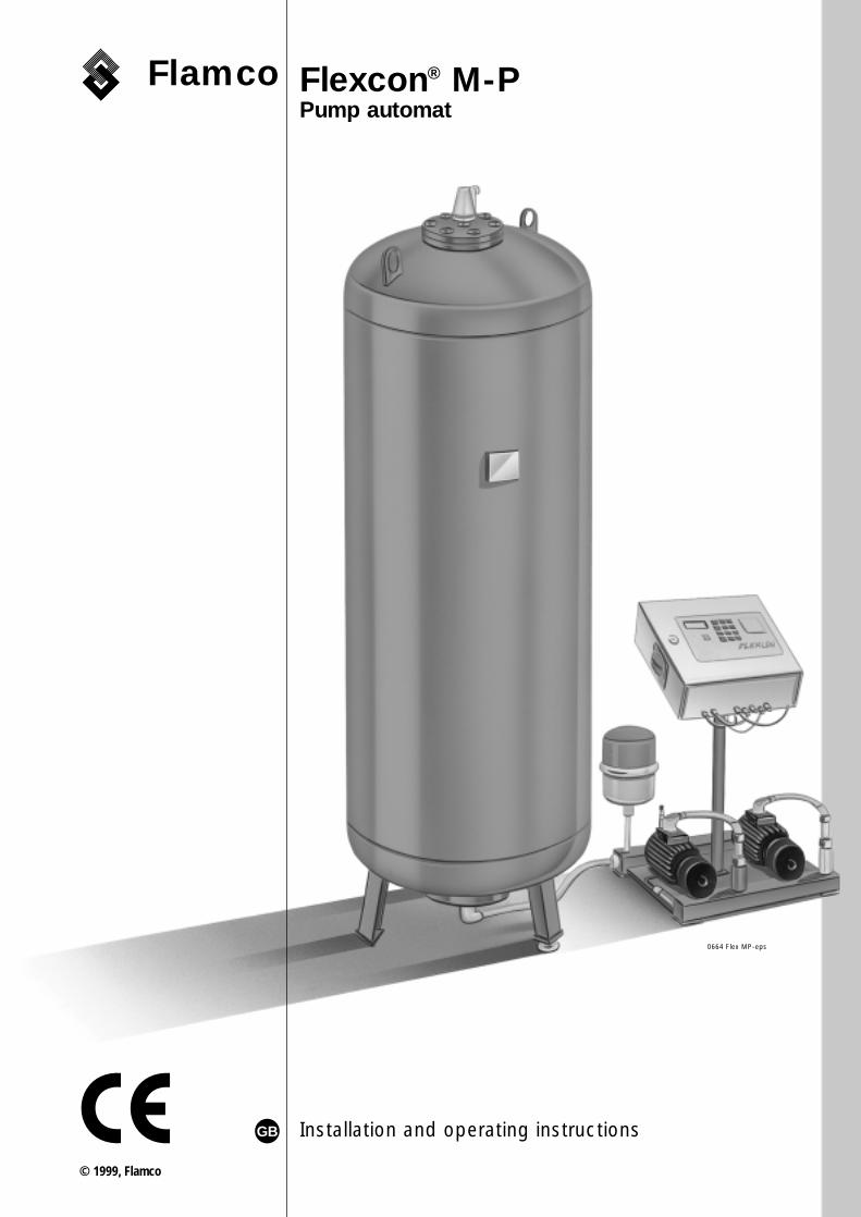
Flamco Flexcon® M-PPump automat
Installation and operating instructionsGB
© 1999, Flamco
0664 Flex MP-eps
18503379 M-P GB 02-03-2000 15:07 Pagina 1

Flamco
2
18503379 M-P GB 02-03-2000 15:07 Pagina 2
Flamco
3
Installation and operating instructionsFlexcon M-P pump automat
Dear customer,
With the purchase of the Flexcon M-P pump automat, you are now the owner of a highquality product from Flamco.
The Flexcon M-P pump automat offers trusted technique, operational reliability andsimplicity with installation and operation.
This manual is intended for siting and placing, and for the commissioning. The manual alsocontains a description of the operation of the Flexcon M-P pump automat.
We are convinced that you will quickly become acquainted with the technique of thisFlexcon M-P pump automat.
Should you have any questions about the Flexcon M-P pump automat that are notanswered in the manual, we will be very pleased to answer them.
Contents page
1.General 4
2.Function and operation 5
3.Different versions 6
4.Siting and placing 8
5.The Easycontrol automat 11
6.The Flexcon control automat 16
7.Commissioning and operation 22
8.Maintenance - periodic inspections 23
Appendices I - VI 24
GB
18503379 M-P GB 02-03-2000 15:07 Pagina 3
Flamco
4
1.General
Flexcon M-P pump automats are used in closed heating installations, cooling and airconditioning installations with large water contents.
The automats absorb the expansion volume that arises through heating in the installation.When the temperature falls, the required amount of water is again made available. Here, a servo-magnet valve is used to feed the expansion water into the diaphragm of theexpansion vessel, and a pump is used to return the water to the installation.
Flexcon M-P pump automats provide a considerably better solution than the pressuredictation systems that are known with installations for hot water production. The reason isthat the expansion water is not connected to the atmosphere and, in this way, damagethrough corrosion is avoided.
Thus, the Flexcon M-P pump automats ensure an accurate setting and maintenance ofthe pressure required in the installation.
1.1 Fields of application
The Flexcon M-P pump automats can be used in closed heating installations, according toDIN 4751, Part 2, with water supply temperatures to a maximum of 120 °C and also inclosed cooling and air conditioning installations.
The Flexcon M-P pump automats are designed for:• Maximum allowed water supply temperature of the heating installation: 120 °C• Maximum continuous temperature loading of the diaphragms, according to
DIN 4751, Part 3: 70 °C• Maximum allowed working pressure: 10 bar• Special versions over 10 bar, on request.
With a temperature > 70 °C in the expansion pipe-work between the heating installationand the Flexcon M-P pump automat, a cooling vessel* is connected in front of theexpansion vessel to cool the expansion water.
The Flexcon M-P pump automats can be supplied in series with sizes of 200 to 5200litres.
* Flexcon V-B cooling vessels:– volumes from 180 to 2000 litres– maximum allowed working pressure: 5.0 to 10.0 bar
1.2 Specifications and regulations
The diaphragm expansion vessels are pressure-less in the state for use. The vessels aredesigned for installations according to DIN 4751 part 2 after TRD 702.
The test certificates (factory declaration) are included in the delivery and must be given tothe locally responsible authorities for viewing.
The installation and operating manual and the test certificates are kept in the cabinet of theautomat!
The test that must be carried out after the installation at the operational site must beorganised by the exploitant.
1.3 Advantages of using the Flexcon M-P pump automat
– complete programme in size, design and pressure stages.– broad applicability as a result of flexible possibilities of use.– small placement surface - large expansion volume in a small space.– use of low-noise pumps with high capacity to produce pressure, with automatic venting
of the pump.– storage of expansion water in pressure-less operating vessels with solid diaphragm
made of high-quality butyl rubber.– the pressure in the system is kept constant within tight limits, which means minimum
pressure variations, independent of the state of the system.– minimisation of pressure shocks and reduction of switching frequency of the pump and
solenoid valve as a result of an integrated pressure control vessel.– freely programmable control with a microprocessor, whereby the actual values in use and
all operational states are shown on a display.– connection to a personal computer or combination with a building control system
possible.– connection to a general fault indication present.– safe operation through many years of experience and high manufacturing quality.
18503379 M-P GB 02-03-2000 15:07 Pagina 4

Flamco
5
2. Function and operation
Functional diagram of a Flexcon M-P pump automat
Figure 1
Figure 1 shows the Flexcon M-P pump automat.In the standard version, the pump automat consists of the following two components:- Flexcon M-P diaphragm expansion vessel- Flexcon M-P automatic control of the pump
The essential constructional parts of the two components are:- Flexcon M-P diaphragm expansion vessel• vessel (1)• diaphragm (2)
- Flexcon M-P automatic pump control• control automat (3)• heavy duty pump (4)• overflow valve (5)
The diaphragm (2), which is in the expansion vessel (1), absorbs the expansion volume andfunctions as a separation wall between air and water. The control automat (3) guaranteesthat the system pressure which is set in the control is kept constant within tight limits. Thesignal that is necessary for this is sent to the automat by the pressure sensor (6). When thetemperature rises, the pressure in the system increases. The overflow valve (5) opens andlets the expansion water flow into the Flexcon M-P diaphragm expansion vessel. When thetemperature drops, the pressure in the system decreases. If the pressure falls below the setsystem pressure, the pump (4) switches on, and is switched off when the system pressureis reached. A check and a continuous indication of the filling level in the display (3) preventsthe pump (4) from running dry or the vessel (1) from being filled to an unallowably highlevel. The Flexcon M-P pump automat can be fitted with the following microprocessorcontrols:
• Easycontrol automatThe Easycontrol automat is designed for single installations (a Flexcon M-P expansionautomat with coupling vessel). For operation, see pages 11 to 15.
• Flexcon control automatThe Flexcon control automat is prepared for single installations, and for failure change-overoperation by two pumps. For operation, see pages 16 to 21.
recommendedon-site
assemblyfrom
M-P 1000 l
3
15
plugSteuerautomat
expansion pipe-worksystem connection
2
1
14 13
19 20
167
6
8
2010912
11
54
17
18
1 Steel vessel2 Exchangeable diaphragm made from butyl
rubber, according to DIN 4807, Part 33 Control automat4 Heavy duty pump5 Overflow valve6 Pressure sensor7 Contents sensor8 Safety valve9 Non-return valve
10 Dirt catcher11 Pressure control vessel
12 Ball valve13 Floatvent14 Aerator and de-aerator15 Earth connection16 Connecting pipe between diaphragm17 Filling-drain cock18 Pump vent (valve, floating vent)19 Flexible hose connection20 Safety valve - fit on site!
6553
18503379 M-P GB 02-03-2000 15:07 Pagina 5

Flamco
6
A solid diaphragm of butyl rubber divides the Flexcon M-P diaphragm expansion vesselinto a water and gas space.The diaphragm prevents contact between the expansion water and atmospheric oxygen.Via a floating aerator and vent (13), air that is released from the heating water is optimallyseparated and prevents an enrichment of the heating water with air from the atmosphere.The safety valve (8) protects the pressure-less vessel (1) from unpermitted overpressure inthe case of a failure.The supply and removal of expansion water to and from the diaphragm is done by theflexible high pressure hose (19) between the diaphragm expansion vessel and theautomatic pump. The pressure control vessel (11) thus reduces the pressure shocks whenthe pump and the servo solenoid valve switch.
3. Different versions
The different versions that are described in the following can be supplied for the variedrequirements that the heating installations place on the expansion automats.If you wish to realise other versions, please contact your local Flamco representative.The design can be effectively realised with the help of the Flamco calculation diskette* forexpansion vessels.
* Available on request from the Sales Office of Flamco.
3.1 Flexcon M-P pump automat
The standard version of the Flexcon M-P pump automat is supplied in two components:- Flexcon M-P diaphragm expansion vessel in the sizes 200 to 5000 litres (upright) with
flexible high pressure hose- Flexcon M-P automatic control including a pump
Figure 2
3.2 Flexcon M-P pump automat with auxiliary vessel
Figure 3
With a battery or series circuit of Flexcon M-P pump automats with an automatic pump(Flexcon M-P pump automat with auxiliary vessel), care must be taken that theexpansion vessel is of the same size. The automats can be supplied with both controlautomats (Flexcon control automat or Easycontrol automat).
Expansion pipe-work
Expansion pipe-workInstall on site
6554
6555
18503379 M-P GB 02-03-2000 15:07 Pagina 6

Flamco
7
3.3 Parallel operation or failure change-over operation by two pumps*
Figure 4
With the Flexcon M-P pump automat with one M-P control and two pumps, only one of thetwo pumps works during failure change-over operation.In the case of a fault (the motor protection switch becomes active), the systemautomatically switches over to the other pump. This is also done after expiry of the setchange time, which serves to load the pumps evenly.
* Only with Flexcon control automat - see page 16.
Expansionpipe-work
PlugSteuerautomat
6556
18503379 M-P GB 02-03-2000 15:07 Pagina 7
Flamco
8
4. Siting and placing
The Flexcon M-P pump automat is supplied as standard version in two packages.Appendix VI gives the main dimensions and weights.1. Diaphragm expansion vessel2. Automatic pump control
The Flexcon M-P pump automat must be placed in closed spaces with a temperaturebetween 5 °C and 40 °C. Here, the floor must be sufficiently sturdy and flat.
Caution: The expansion vessel and the control must be installed at the sameheight. If this is not structurally possible, the expansion vessels may beplaced higher than the control. The control is not allowed to be higherthan the expansion vessels!
Flexcon M-P pump automats must be so placed that they can operate without problemsand can be maintained at all times.
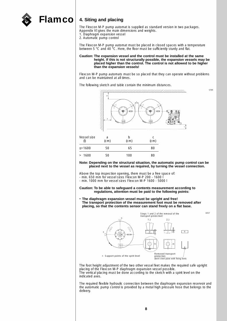
The following sketch and table contain the minimum distances.
Vessel size a b c(l) (cm) (cm) (cm)
≤=1600 50 065 80
> 1600 50 100 80
Note: Depending on the structural situation, the automatic pump control can beplaced next to the vessel as required, by turning the vessel connection.
Above the top inspection opening, there must be a free space of:- min. 650 mm for vessel sizes Flexcon M-P 200 - 1600 l- min. 1000 mm for vessel sizes Flexcon M-P 1600 - 5000 l
Caution: To be able to safeguard a contents measurement according toregulations, attention must be paid to the following points:
• The diaphragm expansion vessel must be upright and free!The transport protection of the measurement foot must be removed afterplacing, so that the contents sensor can stand freely on a flat base.
The foot height adjustment of the two other vessel feet makes the required safe uprightplacing of the Flexcon M-P diaphragm expansion vessel possible.The vertical placing must be done according to the sketch with a spirit level on theindicated axes.
The required flexible hydraulic connection between the diaphragm expansion reservoir andthe automatic pump control is provided by a metal high pressure hose that belongs to thedelivery.
Steps 1 and 2 of the removal of the transport protection!
Support points of the spirit levelRemoved transportprotection(bent steel plate with fixing bolt)
1.) 2.)
b
a
c
c
Steuerautomat
5709
6557
18503379 M-P GB 02-03-2000 15:07 Pagina 8

Flamco
9
• The zero level setting of the vessel contents may only take place with an emptyand exactly vertical vessel!
Before the commissioning of the expansion automat (see also chapter 7), no water may beadded and the vessel must be kept separated from the mains (safety valve closed).
After the components of the Flexcon M-P pump automat are placed, the followingconnections can be made:
a) Hydraulic connectionsThe connection of the installation to the automatic pump control can be stiff or flexible,but must be fitted with a shut-off valve.The connections are dependent on the chosen expansion pump, as follows:
Pump type System connectionM-P/1.0 G 1!/4�/DN 32M-P/2.0 G 2� /DN 50M-P/3.0 G 2� /DN 60
The connection between the control and the expansion vessel must be flexible.
Here, the following must be taken into account:- It must be possible to shut the pump automat off from the installation. This valve must be
protected against unintended closing (for example, a valve with a seal).- Welding activities must be so carried out that no welding material can fall on or enter the
pump automat.- The maximum working temperature at the system connection may not exceed 70 °C
(generally speaking, the system connection must be coupled into the return pipe-work ofthe boiler).
b) Electrical connectionThe control must be connected to 400 V, 50 Hz, 16 A.
Here, attention must be paid to the following:- The voltage and the frequency values must correspond with the DIN VDE
recommendations.- The connection must be made with a 400 V CEE wall socket (according to IEC 309-2).- The earth connection (zero earth potential difference) must be made to an earth leakage
connection (according to DIN VDE 0100, part 540) through the central earthing bolt ofthe control automat (see figure 1, item number 13).
c) Connection of the contents sensor for the contents level measurementThe electrical connection of the contents sensor to the measurement foot of thediaphragm expansion vessel must be made on site with the cable which is supplied withthe delivery (this is connected to the control in the factory). Here, the 5-pole round plugmust be connected to with the measurement probe.Both the Flexcon M-P expansion automat in the standard version (chapter 3.1 figure 2)and the Flexcon M-P expansion automat with M-P automatic pump control in the versionwith two pumps (point 3.3 figure 4) are delivered ready for use in two components.Assembly recommendation: Flexcon M-P expansion automat
Directly heated installation (Connection through protected shut-off valve)
Figure 5
1 Flexcon M-P expansion automat2 Valve (with wire and lead seal)3 Filling-drain cock (included in delivery)4 Flexcon diaphragm expansion vessel5 Safety valve
6 Flamco low water level protection7 Pressure meter8 Flexvent floating vent9 Air separator
56 6
4
7
8
7
4
5
9
1
23
5711
18503379 M-P GB 02-03-2000 15:07 Pagina 9

Flamco
10
Assembly recommendation for the Flamco-Fill STA or PA automatic waterreplenisher
The hydraulic coupling of a automatic water replenisher must be made according to figure 6.
Figure 6
Pump type Coupling*M-P/1.0 Double nipple 1!/4� +
T-piece 1!/4� - !/2� - 1!/4�
M-P/2.0 Double nipple 2� +M-P/3.0 T-piece 2� - !/2� - 2�
* is not part of the delivery
Coupling
Replenisherconnection
6558
18503379 M-P GB 02-03-2000 15:07 Pagina 10
Flamco
11
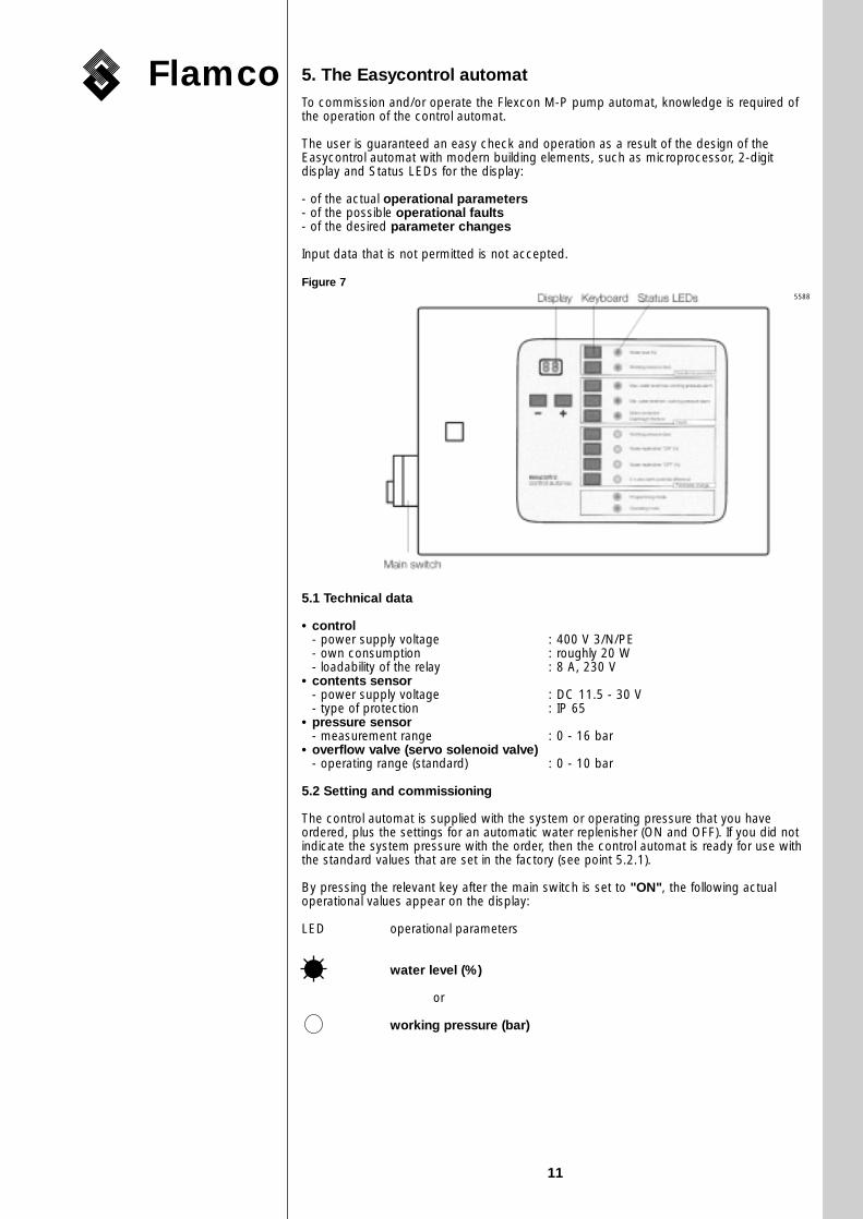
5. The Easycontrol automat
To commission and/or operate the Flexcon M-P pump automat, knowledge is required ofthe operation of the control automat.
The user is guaranteed an easy check and operation as a result of the design of theEasycontrol automat with modern building elements, such as microprocessor, 2-digitdisplay and Status LEDs for the display:
- of the actual operational parameters- of the possible operational faults- of the desired parameter changes
Input data that is not permitted is not accepted.
Figure 7
5.1 Technical data
• control- power supply voltage : 400 V 3/N/PE- own consumption : roughly 20 W- loadability of the relay : 8 A, 230 V
• contents sensor- power supply voltage : DC 11.5 - 30 V- type of protection : IP 65
• pressure sensor- measurement range : 0 - 16 bar
• overflow valve (servo solenoid valve)- operating range (standard) : 0 - 10 bar
5.2 Setting and commissioning
The control automat is supplied with the system or operating pressure that you haveordered, plus the settings for an automatic water replenisher (ON and OFF). If you did notindicate the system pressure with the order, then the control automat is ready for use withthe standard values that are set in the factory (see point 5.2.1).
By pressing the relevant key after the main switch is set to "ON", the following actualoperational values appear on the display:
LED operational parameters
water level (%)
or
working pressure (bar)
5588
18503379 M-P GB 02-03-2000 15:07 Pagina 11

Flamco
12
If you did indicate the working parameters with your order, you only need to carry out thezero level setting (fourth operational step) in the programming mode (see chapter5.2.1) for:
- working pressure (bar)- automatic water replenisher "ON" (%)- automatic water replenisher "OFF" (%)
If no working parameters were entered beforehand or if the set working parameters mustbe changed, you must carry out the relevant operational steps in the following section.
5.2.1 Changing the operational parameters
To change the operational parameters, the following operational steps are required:
- main switch : OFF- control automat : OPEN- sliding switch (colour red) on the control panel : OPERATE SWITCH- control automat : CLOSE- main switch : ON
The programming mode LED is lit!
Figure 8
In the programming mode, the display shows the following:
First operational step
Operate the
. working pressure (bar)
or
• automatic water replenisher "ON" (%)
or
• automatic water replenisher (OFF) (%)
key for three seconds.
The relevant LED will light. The display will show the value that was entered in the factory or that was saved last!
Values of parameters that the factory enters (without previous values!)
• working pressure values• Flexcon M-P 10 bar 5.5 bar• automatic water replenisher "ON" 15 %• automatic water replenisher "OFF" 25 %
0 0
Sliding switch (red) operate programming
Easycontrol (open)
6634
18503379 M-P GB 02-03-2000 15:07 Pagina 12

Flamco
13
Example: Working pressure (bar)
The following appears in the display:
- the figure after the decimal point "flashes"
Second operational step:
Correct the "flashing figure" by operating the keys
or
and confirm with the "Working pressure" key
If the displayed value has to remain unchanged, you canconfirm this by only operating the "working pressure" key.
- the figure in front of the decimal point "flashes"
Third operational step:
Repeat the second operational step!
The operational steps are analogous to the "working pressure example" for theindication and if necessary the desired change of the entered values for:
automatic water replenisher "ON"
and
automatic water replenisher "OFF"
Note!The values can only be changed within the range limits that are previously set in thefactory.
If the set value is within the range limits, the relevant LED goes out after about fiveseconds.
If the value is outside the range limits, the entry must be repeated with plausible values.
If a change of the parameters is desired, the values can be changed within the followingrange limits:
• working pressure - rangeFlexcon M-P 10 bar 0.5 to 8.7 bar
• automatic water replenisher "ON" - range5 % to 49 %
• automatic water replenisher "OFF" - rangereplenisher "On" + 2 %to replenisher "On" + 20 %
Example- automatic water replenisher "ON" : 06 %- automatic water replenisher "OFF" : 12 %
Note:The values for the minimum and maximum permitted water level are programmedas fixed values.• min. water level : 05 %• max. water level : 94 %
If these values become too high or low during operation, this will cause a fault report (seealso point 5.3 "Reporting - operational faults").
2 . 8
2 . 8
- +
18503379 M-P GB 02-03-2000 15:07 Pagina 13

Flamco
14
Contents level - zero level setting
Caution:The "operational zeroing", i.e. the zero level setting of the filling level may onlytake place with an empty vessel and with the transport protection removed (see also chapter 4 - Siting and placing).
Fourth operational step
Key • zero level setting operate for three seconds.
The zero level setting is finished when the appropriate LED goes out after about fiveseconds. If the LED flashes eight times, the operational step must be repeated.
Caution!After finishing the value change, the equipment must be switched to the"operation" mode because the control cannot otherwise operate (operationalmode LED)!
The switch-over to the "operation" mode after the earlier set parameters are changed mustbe carried out as follows:
Operational steps:
- main switch : OFF- control automat : OPEN- sliding switch (colour red) on the control panel (fig. 9) : OPERATE SWITCH- control automat : CLOSE- main switch : ON
Note!The following LED is lit because the vessel of the Flexcon M-P expansionautomat is empty:
Minimum water level/alarm for minimum working pressure
The minimum water level fault serves as a protection against the pump runningdry. The pump is blocked and switches off!
The Flexcon M-P expansion automat of the expansion installation must be filledwith water (see also chapter 7 "Commissioning - operation").
5.3 Reporting - operational faults
The control automat is equipped with a detailed fault indication. A possible fault report isgiven by the relevant "operational fault LED" lighting, in combination with the"operational parameter LED".
To leave the fault reports after clearing the faults, operate the relevant key.
Caution!With a motor protection fault, the contact for too high current has activated. This fault must be cleared by a qualified person!
If you cannot clear the general or other faults, please contact our customer servicedepartment.
5.4 Connection of a general fault indication ("Fehler")
Faults in the heating installation or the control are reported by the potential-free change-over contact. The contacts are connected to terminals x 1 - 11, 12 and 13 of the controlautomat (see "terminal plan" appendix I).
Warning!Even with a switched off control, there can be voltage on the connections of thefault relay (external power supply).
5.5 Connection of an automatic water replenisher - Flamco-Fill Type STA or PA
A potential-free contact is available on terminals x 1 - 9 and 10 to control the automaticwater replenisher. The contact closes at the water replenish command from the control(see "terminal plan" appendix I).
Warning!Even with a switched off control, there can be voltage on the connections of thefault relay (external power supply).
18503379 M-P GB 02-03-2000 15:07 Pagina 14
Flamco
15
5.6 Automatic leakage detection
The Flexcon M-P pump automat can be supplied with a "leakage probe" to detect possibledamage to the diaphragm.
With damage to the diaphragm, whereby water penetrates the air space of thediaphragm expansion vessel and especially air enters the installation, there is an immediatealarm on the display of the Flexcon control automat.
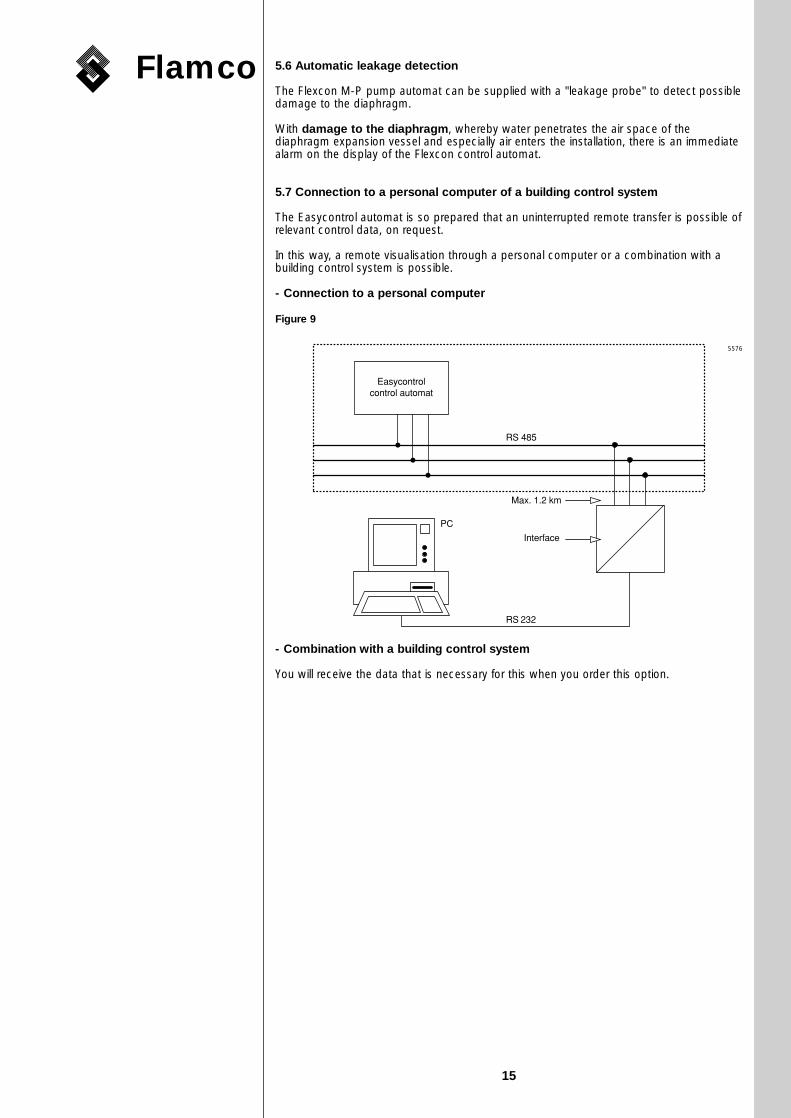
5.7 Connection to a personal computer of a building control system
The Easycontrol automat is so prepared that an uninterrupted remote transfer is possible ofrelevant control data, on request.
In this way, a remote visualisation through a personal computer or a combination with abuilding control system is possible.
- Connection to a personal computer
Figure 9
- Combination with a building control system
You will receive the data that is necessary for this when you order this option.
Easycontrol�control automat� �
RS 485 �
Max. 1.2 km� �
Interface
RS 232
PC
�
5576
18503379 M-P GB 02-03-2000 15:07 Pagina 15
Flamco
16
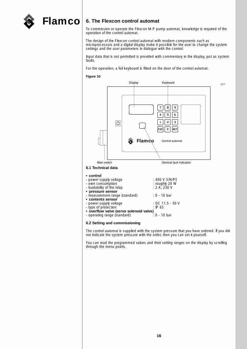
6. The Flexcon control automat
To commission or operate the Flexcon M-P pump automat, knowledge is required of theoperation of the control automat.
The design of the Flexcon control automat with modern components such asmicroprocessors and a digital display make it possible for the user to change the systemsettings and the user parameters in dialogue with the control.
Input data that is not permitted is provided with commentary in the display, just as systemfaults.
For the operation, a foil keyboard is fitted on the door of the control automat.
Figure 10
6.1 Technical data
• control- power supply voltage : 400 V 3/N/PE- own consumption : roughly 20 W- loadability of the relay : 2 A, 230 V• pressure sensor- measurement range (standard) : 0 - 10 bar• contents sensor- power supply voltage : DC 11.5 - 30 V- type of protection : IP 65• overflow valve (servo solenoid valve)- operating range (standard) : 0 - 10 bar
6.2 Setting and commissioning
The control automat is supplied with the system pressure that you have ordered. If you didnot indicate the system pressure with the order, then you can set it yourself.
You can read the programmed values and their setting ranges on the display by scrollingthrough the menu points.
Display Keyboard�
Control automat
General fault indication�Main switch
Flamco
5577
18503379 M-P GB 02-03-2000 15:07 Pagina 16

Flamco
17
After the main switch is set to "ON", the following appears on the display:
(Here, the system pressure was set to 2.0.)By pressing the <RET> key, you can call further menus:
Operating hours
Pump 1 000000 hoursPump 2 000000 hours
Options
Leakage probe : - (*)Parallel operation : -Failure change-over operation : -
- = not present* = present
Installation : M-PWorking pressure : 10 barContents : XXXX L
X = nominal vessel contents
To change the operational parameters that are set in the factory, the control must beswitched from the "BETRIEBS-Modus" (operational mode) to the "PROGRAMMIER-Modus" (programming mode).
Switching to the programming mode
operational steps
- Main switch : OFF- Control automat : OPEN- Sliding switch (colour red) on the inside of the door : OPERATE SWITCH- Control automat : CLOSE- Main switch : ON
Figure 11
Caution!• Automat operation is not possible in the programming mode.• The programming mode is indicated by a flashing report "Fehler".
Sliding switch (red)
On - Programming
� �Flexcon control automat� (opened)
�� �
Pressure Level
00.0 bar 000 %01.7 Pump. 005 %02.3 Vent. 095 %
6559
18503379 M-P GB 02-03-2000 15:07 Pagina 17

Flamco
18
The display is as follows:
Programming modefurther with "RET"orswitch on
Operate <RET> key, the display now becomes:
- Menu point 1
System pressure : 02.0Allowed : 00.6 - 08.3 barConfirmation : "RET"
The value can be changed within the indicated range limits.
Each time the <RET> key is operated, the next menu point appears.
- Menu point 2
Min. water level : 05 %Allowed : 5 % to 50 %Confirmation : "RET"
(standard: 5 %)
- Menu point 3
Max. water level : 95 %Allowed : 50 % to 95 %Confirmation : "RET"
(standard: 95 %)
- Menu point 4
Min. pressure : 00.5Allowed : X.X - XX.X barConfirmation : "RET"
Value can be changed within the indicated range limits "X.X to XX.X".
- Menu point 5
Max. pressure : 04.5Allowed : XX.X - XX.X barConfirmation : "RET"
Value can be changed within the indicated limits "XX.X to XX.X".
- Menu point 6
Water make-up levelSwitches on at : 04 %Allowed : 04 to 49 %Confirmation : "RET"
- Menu point 7
Water make-up levelSwitches off at : 10 %Allowed : XX to XX %Confirmation : "RET"
Value can be changed within the indicated range limits "XX to XX".
- Menu point 8
Maximum pump running time : 10 minAllowed : 10 to 240 minConfirmation : "RET"
Value can be changed within the indicated range limits.
18503379 M-P GB 02-03-2000 15:07 Pagina 18

Flamco
19
- Menu point 9 (Optional)
Parallel operation1: present2: not present
(for this, see point 3)
- Menu point 10
Zero level setting of the contents sensoroperate : "ESC"further : "RET"
Caution!The zero level setting of the vessel contents may only take place with an emptyvessel and removed transport protection! (See also chapter 4 "Siting and placing".)
The zero level setting may only be carried out if the electronics are at working temperature(roughly ten minutes after switching on).
After the preset operational parameters are changed, the change-over to the operationalmode must be carried out as follows:
Operational steps:
- main switch : OFF- control automat : OPEN- sliding switch on the inside of the door (figure 9) : ON- control automat : CLOSE- main switch : ON
The Flexcon M-P pump automat is ready for use!
Note:The general fault lamp is on because the vessel or the expansion installation is"empty" and for that reason the "minimum water level" fault is reported.
You must now fill the diaphragm expansion vessel of the Flexcon M-P pump automat (forthis, see chapter 7: "Commissioning - operation".
6.3 Fault reports
The control automat is equipped with a general fault indication. The alarm relay is de-energised when a fault occurs. The <Fehler> (Fault) lamp at the bottom of the display(figure 10) lights continuously.
The faults are given separately in the display.
With more than one fault at a time, the separate fault reports can be displayed byoperating the <RET> key.
After this, the following displays are possible:
FAULTmin. water levelclear fault!
This means that the entered minimum water level (point 6.2 - menu point 2) has not beenreached.
CAUTION:The min. water level fault serves as a protection against the pump running dry.The pump is blocked and switches off!
In this case, it is necessary to refill the installation.
FAULTmax. water levelclear fault!
Here, the preset maximum water level has apparently been exceeded. You can let waterdrain away with the aid of the drain devices that are fitted in the installation.
FAULTmin. pressure alarmclear fault!
18503379 M-P GB 02-03-2000 15:07 Pagina 19
Flamco
20
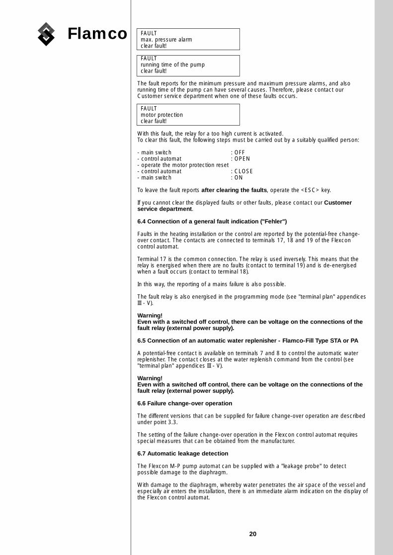
FAULTmax. pressure alarmclear fault!
FAULTrunning time of the pumpclear fault!
The fault reports for the minimum pressure and maximum pressure alarms, and alsorunning time of the pump can have several causes. Therefore, please contact ourCustomer service department when one of these faults occurs.
FAULTmotor protectionclear fault!
With this fault, the relay for a too high current is activated.To clear this fault, the following steps must be carried out by a suitably qualified person:
- main switch : OFF- control automat : OPEN- operate the motor protection reset- control automat : CLOSE- main switch : ON
To leave the fault reports after clearing the faults, operate the <ESC> key.
If you cannot clear the displayed faults or other faults, please contact our Customerservice department.
6.4 Connection of a general fault indication ("Fehler")
Faults in the heating installation or the control are reported by the potential-free change-over contact. The contacts are connected to terminals 17, 18 and 19 of the Flexconcontrol automat.
Terminal 17 is the common connection. The relay is used inversely. This means that therelay is energised when there are no faults (contact to terminal 19) and is de-energisedwhen a fault occurs (contact to terminal 18).
In this way, the reporting of a mains failure is also possible.
The fault relay is also energised in the programming mode (see "terminal plan" appendicesIII - V).
Warning!Even with a switched off control, there can be voltage on the connections of thefault relay (external power supply).
6.5 Connection of an automatic water replenisher - Flamco-Fill Type STA or PA
A potential-free contact is available on terminals 7 and 8 to control the automatic waterreplenisher. The contact closes at the water replenish command from the control (see"terminal plan" appendices III - V).
Warning!Even with a switched off control, there can be voltage on the connections of thefault relay (external power supply).
6.6 Failure change-over operation
The different versions that can be supplied for failure change-over operation are describedunder point 3.3.
The setting of the failure change-over operation in the Flexcon control automat requiresspecial measures that can be obtained from the manufacturer.
6.7 Automatic leakage detection
The Flexcon M-P pump automat can be supplied with a "leakage probe" to detectpossible damage to the diaphragm.
With damage to the diaphragm, whereby water penetrates the air space of the vessel andespecially air enters the installation, there is an immediate alarm indication on the display ofthe Flexcon control automat.
18503379 M-P GB 02-03-2000 15:07 Pagina 20
Flamco
21
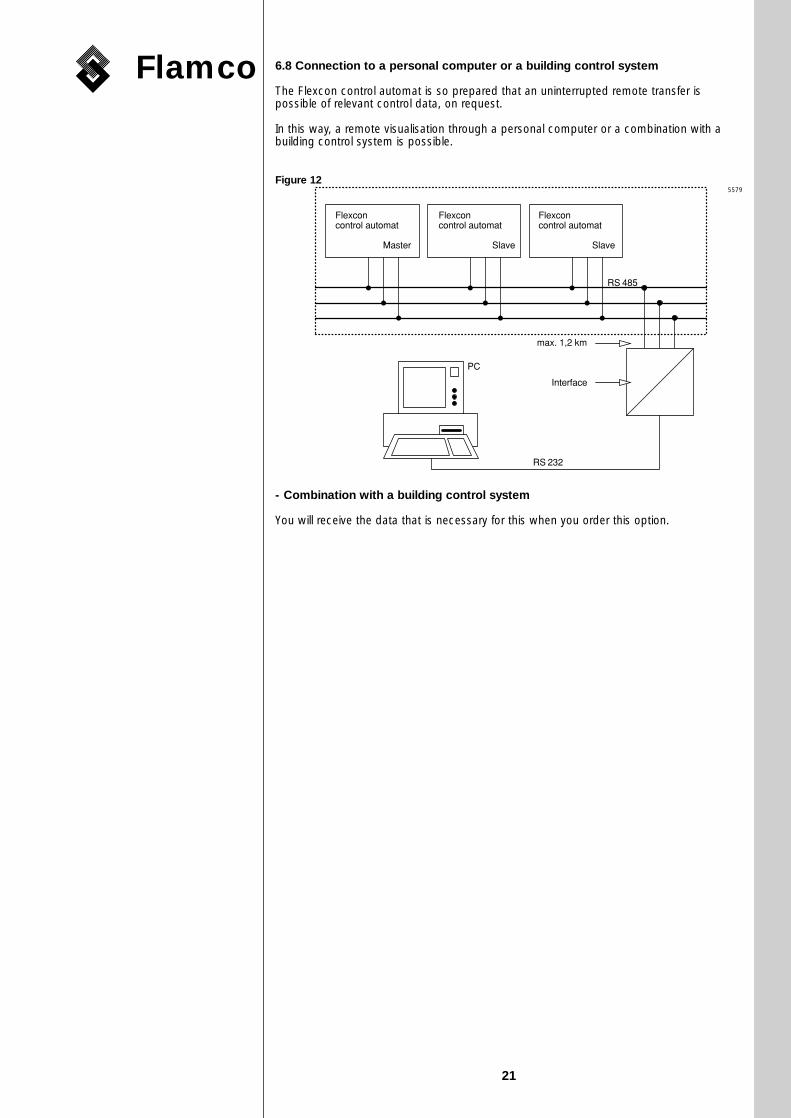
6.8 Connection to a personal computer or a building control system
The Flexcon control automat is so prepared that an uninterrupted remote transfer ispossible of relevant control data, on request.
In this way, a remote visualisation through a personal computer or a combination with abuilding control system is possible.
Figure 12
- Combination with a building control system
You will receive the data that is necessary for this when you order this option.
Flexcon�control automat
Master
Flexcon�control automat
Slave
Flexcon�control automat
Slave
max. 1,2 km �
Interface
RS 232
RS 485
PC
5579
18503379 M-P GB 02-03-2000 15:07 Pagina 21
7. Commissioning and operation
7.1 Commissioning with a cold heating installation
• Valve closed, check the system pressure.
• Carry out a zero level setting of the operation while the vessel is empty.
• Check the pressure of the pressure control vessel and adjust if necessary and then openthe shut-off valve. The setting of the pressure must be carried out as follows:In the state as supplied by the factory, the pressure control vessel has a pressure of 4bar, the ball valve to the Flexcon M-P station (at the bottom of the vessel) is closed. Thepressure of the pressure control vessel must locally be adjusted as follows:Pressure of control vessel* = system pressure - 0.6 bar
Next, the ball valve must be opened.
* If the pressure that is required for the operation in the pressure control vessel is abovethe pressure in the delivery state (4 bar), then this pressure must accordingly be raisedfor the commissioning with nitrogen!
• While the valve between the vessel and the installation is closed, fill the heatinginstallation and vent
• Open vent shut-off of the floating vent ("red knob") on the vessel by turning it one fullturn.
• Fill the Flexcon M-P pump automat (diaphragm expansion vessel) with the plannedamount of water through the filling-drain cock in the expansion pipe-work.
• Vent expansion pipe-work
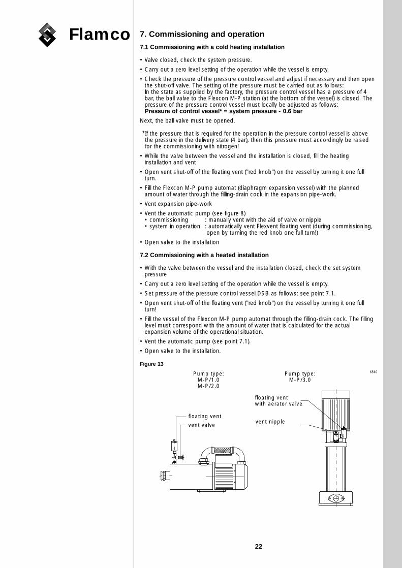
• Vent the automatic pump (see figure 8)• commissioning : manually vent with the aid of valve or nipple• system in operation : automatically vent Flexvent floating vent (during commissioning,
open by turning the red knob one full turn!)
• Open valve to the installation
7.2 Commissioning with a heated installation
• With the valve between the vessel and the installation closed, check the set systempressure
• Carry out a zero level setting of the operation while the vessel is empty.
• Set pressure of the pressure control vessel DSB as follows: see point 7.1.
• Open vent shut-off of the floating vent ("red knob") on the vessel by turning it one fullturn!
• Fill the vessel of the Flexcon M-P pump automat through the filling-drain cock. The fillinglevel must correspond with the amount of water that is calculated for the actualexpansion volume of the operational situation.
• Vent the automatic pump (see point 7.1).
• Open valve to the installation.
Figure 13
Flamco
22
Pump type:M-P/3.0
Pump type:M-P/1.0M-P/2.0
floating vent
floating ventwith aerator valve
vent valvevent nipple
6560
18503379 M-P GB 02-03-2000 15:07 Pagina 22

Flamco
23
8. Maintenance - periodic inspections
The DIN 4807/2 standard requires an annual maintenance and inspection for diaphragmexpansion vessels.
Besides the external condition of the vessel and the correct operation of the control, thepump and overflow valve must be checked for leakage and the dirt catcher must bechecked and cleaned if required.
Moreover, the connecting pipes must be checked for leakage.
If the diaphragm expansion automat is a component of a boiler installation with boilers ofgroup II with a water content of more than 2000 litres that must be inspected for the firsttime by an expert, then a supplementary annual external inspection by an expert must beprescribed, according to paragraph 16 of the Boiler Regulation (DampfV).
In the other case, this check must be carried out by an expert.
The intervals of the periodic inspections have been set as follows, independently of theBoiler Regulation, paragraph 16:
- external check yearly
- internal check every five years
- water pressure check every ten years
The checks must be carried out by an expert.
We advise you to contract the customer service department of Flamco for themaintenance.
(The test of the pressure of the pressure control vessel must take place at least once peryear, in combination with cleaning the dirt catcher).
This manual must be handed over to the owner and must be kept in the vicinity ofthe vessel.
18503379 M-P GB 02-03-2000 15:07 Pagina 23
Flamco
24
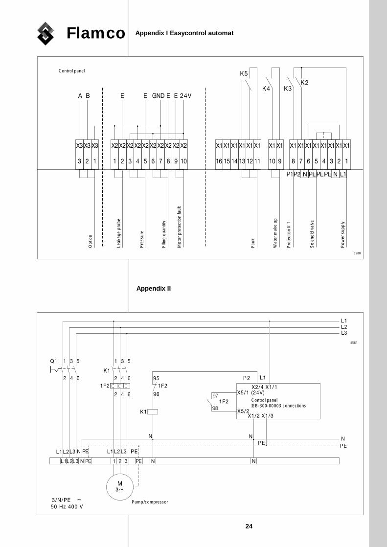
Appendix I Easycontrol automat
Opt
ion
Leak
age
prob
e
Pre
ssur
e
Fillin
g qu
antit
y
Mot
or p
rote
ctio
n fa
ult
Faul
t
Control panel
Wat
er m
ake
up
Sol
enoi
d va
lve
Pow
er s
uppl
y
Pro
tect
ion
K 1
Appendix II
Control panelIEB-300-00003 connections
Pump/compressor
5581
5580
18503379 M-P GB 02-03-2000 15:07 Pagina 24

Flamco
25
Motor protection1
Motor protection2
Protection 1 Protection 2
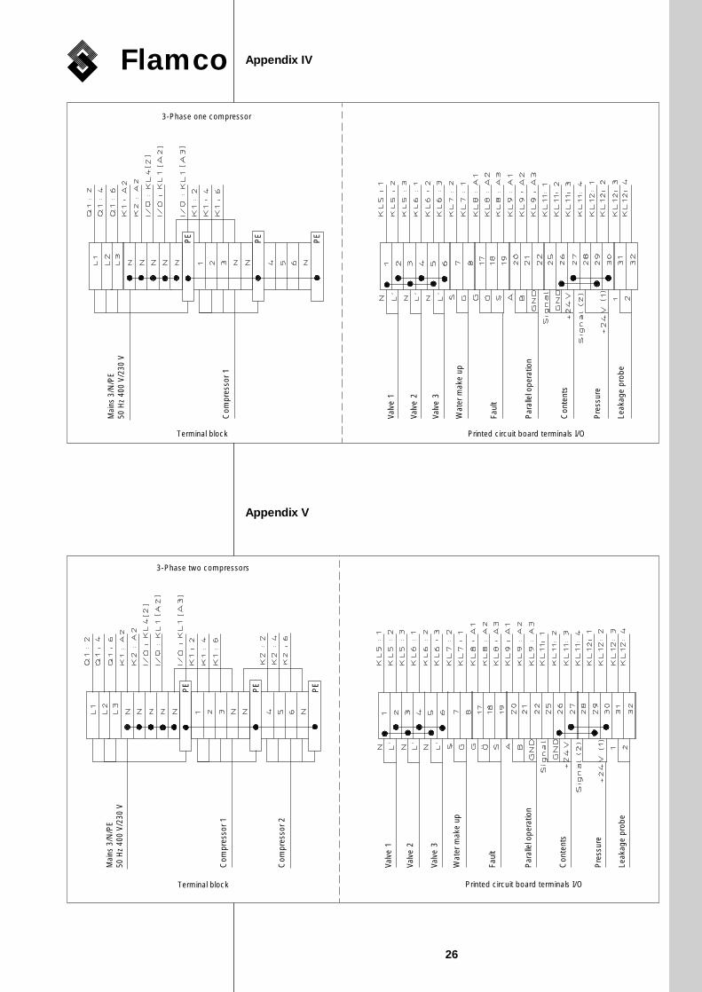
Terminal block Printed circuit board terminals I/O
Power supply Compressor 1 Compressor 2
Appendix III Flexcon control automat
5583
18503379 M-P GB 02-03-2000 15:07 Pagina 25
Flamco
26
Leak
age
prob
e
Mai
ns 3
/N/P
E50
Hz
400
V/23
0 V
Printed circuit board terminals I/OTerminal block
Valv
e1
Valv
e 2
Valv
e 3
Wat
er m
ake
up
Faul
t
Par
alle
l ope
ratio
n
Con
tent
s
Pre
ssur
e
Com
pres
sor 1
3-Phase one compressor
PE
PE
PE
Appendix IV
Appendix V
Leak
age
prob
e
Mai
ns 3
/N/P
E50
Hz
400
V/23
0 V
Printed circuit board terminals I/OTerminal block
Valv
e 1
Valv
e 2
Valv
e 3
Wat
er m
ake
up
Faul
t
Par
alle
l ope
ratio
n
Con
tent
s
Pre
ssur
e
Com
pres
sor 1
Com
pres
sor 2
3-Phase two compressors
PE
PE
PE
18503379 M-P GB 02-03-2000 15:07 Pagina 26
Flamco
27
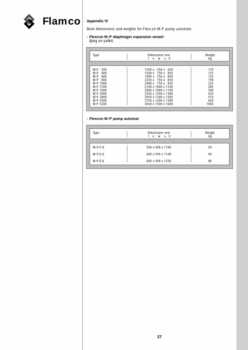
Appendix VI
Main dimensions and weights for Flexcon M-P pump automats
- Flexcon M-P diaphragm expansion vessel (lying on pallet)
- Flexcon M-P pump automat
Type Dimensions mm Weightl x w x h kg
M-P 0200 1350 x 0550 x 0650 0110M-P 0400 1500 x 0750 x 0850 0125M-P 0600 1900 x 0750 x 0850 0155M-P 0800 2350 x 0750 x 0850 0190M-P 1000 2900 x 0750 x 0850 0225M-P 1200 2100 x 1000 x 1100 0285M-P 1600 2600 x 1000 x 1100 0340M-P 2000 2350 x 1200 x 1300 0425M-P 2800 2950 x 1200 x 1300 0510M-P 3500 3750 x 1200 x 1300 0620M-P 5200 3650 x 1500 x 1600 1060
Type Dimensions mm Weigthl x w x h kg
M-P/1.0 590 x 500 x 1100 50
M-P/2.0 600 x 590 x 1100 60
M-P/3.0 600 x 590 x 1250 80
18503379 M-P GB 02-03-2000 15:07 Pagina 27