18-551 spring 2012 group 5 - carnegie mellon university
TRANSCRIPT

18-551 Spring 2012 Group 5 Kelly Chang (klchang) Timothy Farkas (ttf)
Nattamon Thavornpitak (nthavorn)

18-551 Spring 2012 Group 5 Final Report
Android Music Painter
2
TABLE OF CONTENTS
The Problem ............................................................................................................................................................................... 3
The Solution ................................................................................................................................................................................ 3
Novelty .......................................................................................................................................................................................... 3
Existing Technology ................................................................................................................................................................ 4
Implementation Overview .................................................................................................................................................... 5
Signal Flow .................................................................................................................................................................................. 6
Initial Synthesis Implementation ....................................................................................................................................... 6
Final Synthesis Implementation ......................................................................................................................................... 7
Short Time Fourier Transform ................................................................................................................................ 7
Phase Vocoder Interpolation ................................................................................................................................ 10
Inverse Short Time Fourier Transform ............................................................................................................. 13
Polyphase Structures for Sample Rate Conversion by a Non-Integer Factor .................................... 15
GUI Implementation ............................................................................................................................................................. 16
Main Layout .................................................................................................................................................................. 16
Music Notes .................................................................................................................................................................. 17
Touch Capabilities and Editing Functions ........................................................................................................ 18
Application Tutorial ................................................................................................................................................... 18
Menu Options ............................................................................................................................................................... 19
GUI Resources .............................................................................................................................................................. 20
GUI and Code Integration ................................................................................................................................................... 20
Optimization ............................................................................................................................................................................ 21
Schedule and Division of Labor ....................................................................................................................................... 23
Demo ........................................................................................................................................................................................... 24
Future Work ............................................................................................................................................................................ 24
References ................................................................................................................................................................................ 25

18-551 Spring 2012 Group 5 Final Report
Android Music Painter
3
THE PROBLEM
Currently, there are many methods to process and synthesize sound, but they are not intuitive for
people who have not overcome the learning curve of using these existing tools. The programs that
are available often rely on the user having background or initial knowledge in music creation and
processing. Even with this knowledge, these music synthesizers still have so many features and
options that a certain amount of time is required to understand how to process music successfully.
In developing a tool that is easier to use, people will be able to create music without having to
understand complex methods. Even kids will be able to use this tool and express themselves
through music creation. By addressing the intuitive specification of sounds, we will make creating
music not only easy, but also simple and fun.
THE SOLUTION
The application we are proposing will let the user create and edit music without having any
background knowledge in music processing. When using the application, the user will be able to
intuitively specify the frequency and duration of notes for a variety of instruments by leveraging
the touch capabilities of modern Android tablets. In designing and developing this application, the
project was divided into two overall parts and essentially, three main tasks, which are described
below in the implementation section
NOVELTY
Looking into previous projects from 18-551, it was found that many groups worked with music
related topics, ranging from music transcription to music categorization. However, very few groups
focused on music synthesis and of the few that did, the form of input for their project was always a
musical input leading to a musical output. For example, in fall of 2006, Group 9 worked on a vocal
harmony generator. In this project, a vocal input was taken and a harmonizing vocal output was
created. In another project from spring of 2001, Group 7 created a computer generated melody for
their project, where the input was sound from a musical instrument and the resulting output was a
melodic song. A third similar project was from spring of 2003 and was called “Sing-Synth”, a voice
driven synthesizer. In this project, vocal input such as humming or singing was taken and used to
create a musical singing output. As shown, many projects worked on synthesizing music of some
sort but they all started from a musical output. What sets our project apart is that no previous
projects focused on creating and synthesizing music from a non-musical input, which in our case, is
a simple touch interaction on an Android tablet.
18-551 Spring 2012 Group 5 Final Report
Android Music Painter
4
EXISTING TECHNOLOGY
After seeing that there were few similar 18-551 projects, we then explored to see what music
synthesizing applications existed for mobile technologies so we could get ideas to work off of when
moving forward in development. Upon looking into the mobile application stores, it was evident
that while iPhones had a few, Android phones had even fewer. On the whole, there was no
application that was exactly like the one in which we were planning to create. However, of those
that existed, we were able to obtain some ideas of what we may want to include or not include in
our development process.
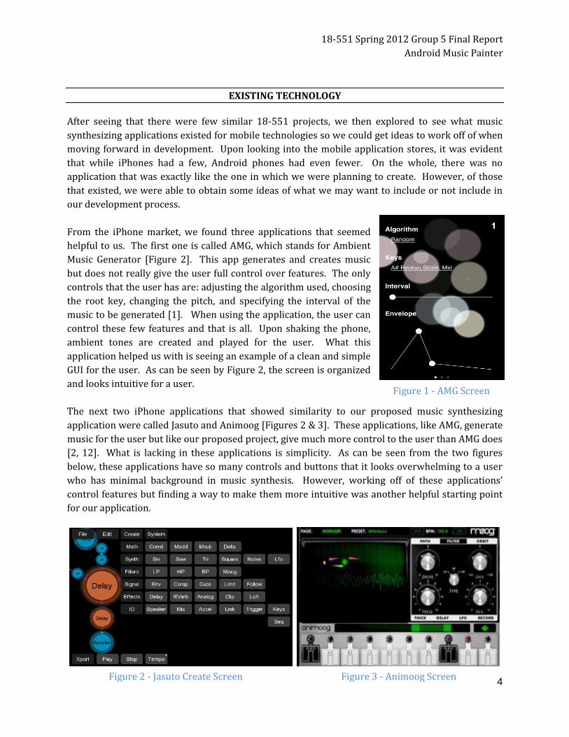
From the iPhone market, we found three applications that seemed
helpful to us. The first one is called AMG, which stands for Ambient
Music Generator [Figure 2]. This app generates and creates music
but does not really give the user full control over features. The only
controls that the user has are: adjusting the algorithm used, choosing
the root key, changing the pitch, and specifying the interval of the
music to be generated [1]. When using the application, the user can
control these few features and that is all. Upon shaking the phone,
ambient tones are created and played for the user. What this
application helped us with is seeing an example of a clean and simple
GUI for the user. As can be seen by Figure 2, the screen is organized
and looks intuitive for a user.
The next two iPhone applications that showed similarity to our proposed music synthesizing
application were called Jasuto and Animoog [Figures 2 & 3]. These applications, like AMG, generate
music for the user but like our proposed project, give much more control to the user than AMG does
[2, 12]. What is lacking in these applications is simplicity. As can be seen from the two figures
below, these applications have so many controls and buttons that it looks overwhelming to a user
who has minimal background in music synthesis. However, working off of these applications’
control features but finding a way to make them more intuitive was another helpful starting point
for our application.
Figure 1 - AMG Screen
Figure 2 - Jasuto Create Screen Figure 3 - Animoog Screen

18-551 Spring 2012 Group 5 Final Report
Android Music Painter
5
On the Android side of things, the only similar application found was
called Android Synthesizer [Figure 4]. This application is in a sense,
a combination of the above two iPhone applications because it
provides more control and features than AMG but also provides
more simplicity than Jasuto [3]. From this application, we were able
to get a feel for what GUI features to include but at the same time,
still keep the overall functionality we wanted to implement. The
buttons used on the screen, the drop-down menu, and the sliding
bars gave us a few good ideas when it came to implementing touch
screen control options for the user.
On the whole, looking at existing technologies showed us that very
few mobile music synthesizer applications currently exist and from
those that do exist, we were able to build a strong foundation of
ideas to work off of.
IMPLEMENTATION OVERVIEW
Our solution to the music synthesis problem can be divided into two parts: a touch screen user
interface and an instrument synthesis algorithm.
For the touch screen interface, Android code was developed so that the user could touch the screen
to add a musical note to the music sheet (the screen). The user could specify the instrument they
wanted to use and the location of their touch would register as the time in music (x-axis value) and
the frequency for the note (y-axis value). The screen was implemented in a scrolling view so that
more time could be allocated to user as needed. In summary, the GUI was made so that the user
could simply touch the screen, edit a few features, and then press play. Upon pressing play, the
user’s work would be used as input to the instrument synthesis algorithm and after synthesizing,
the music would be played to the user.
For the instrument synthesis, we focused on four main instruments when we developed our
synthesis algorithm: the acoustic guitar, bass guitar, piano, and violin. Synthesis of these
instruments can be summarized in 3 steps. First, samples of notes were collected for each
instrument. In the case of the acoustic guitar, bass guitar, and violin, one sample of each string was
collected, and in the case of the piano, samples were collected at several frequencies. After
collecting these samples, a note is synthesized by taking a sampled sound, pitch shifting the
sampled sound to have the desired fundamental frequency, and stretching the sound to have the
desired duration. This is accomplished by using a phase vocoder to first stretch the duration of the
sound (without modifying its frequency characteristics) and then using a poly phase interpolator to
resample the stretched sound in order to shift the pitch appropriately.
Figure 4 – Android
Synthesizer

18-551 Spring 2012 Group 5 Final Report
Android Music Painter
6
SIGNAL FLOW
Our GUI and synthesis algorithm run completely on Android. The only aspects of the project that do
not process on Android are the collection of sound samples for the instruments and the
specification of the fundamental frequencies of those sound samples. These samples and values
were calculated and saved on the computer and directly loaded to the application.
INITIAL SYNTHESIS IMPLEMENTATION
Our first implementation of synthesis is based on a master thesis by Kevin Bradley. Although the
thesis is about synthesizing a guitar sound, the algorithm can be used to analyze and synthesize
other string instruments including a violin, a bass guitar, and a piano. According to Bradley’s thesis,
a guitar sound has two components- a vertical and horizontal response [14]. The vertical
component decays with a faster rate; therefore, after about 0.5 seconds, there is only a horizontal
component. To analyze a sound sample, we first calculate fundamental frequency and period by
computing the auto-correlation of a sound sample. The time lag corresponding to the maximum
auto-correlation apart from when lag = 0, is the fundamental period, which can then be used to
compute the fundamental frequency. After finding the frequency, the ideal string response can be
computed using the following equations [Figure 5]:
where f is the fundamental frequency determined in the first step. L is a pluck point that is
determined by minimizing the mean squared error between the Fourier transform of the actual and
ideal response and H is the initial displacement.
The problem here is that the actual response differs from the ideal one. To account for this, we
compute and store the difference between phases and magnitudes of the Fourier transform of the
ideal and the actual response at each harmonic. Since the vertical response decays faster, it can be
assumed that after 0.5 seconds, there is only the horizontal mode. From the samples after 0.5
seconds, we compute a decay rate and an initial response of the horizontal response. Then, the
entire horizontal response is modeled and subtracted from the actual response producing the
response with the vertical excitation only. The decay rate and initial amplitude for the vertical
mode are computed. To reconstruct the signal, the fundamental period and frequency are used to
calculate the ideal response for each mode and then, we compensate for the difference between the
ideal and actual response. Finally, decay rates and initial amplitudes are taken into account and the
response for each mode is added up. The sum is then convolved with an FIR filter modeling the
Figure 5 – Ideal String Response Equations
18-551 Spring 2012 Group 5 Final Report
Android Music Painter
7
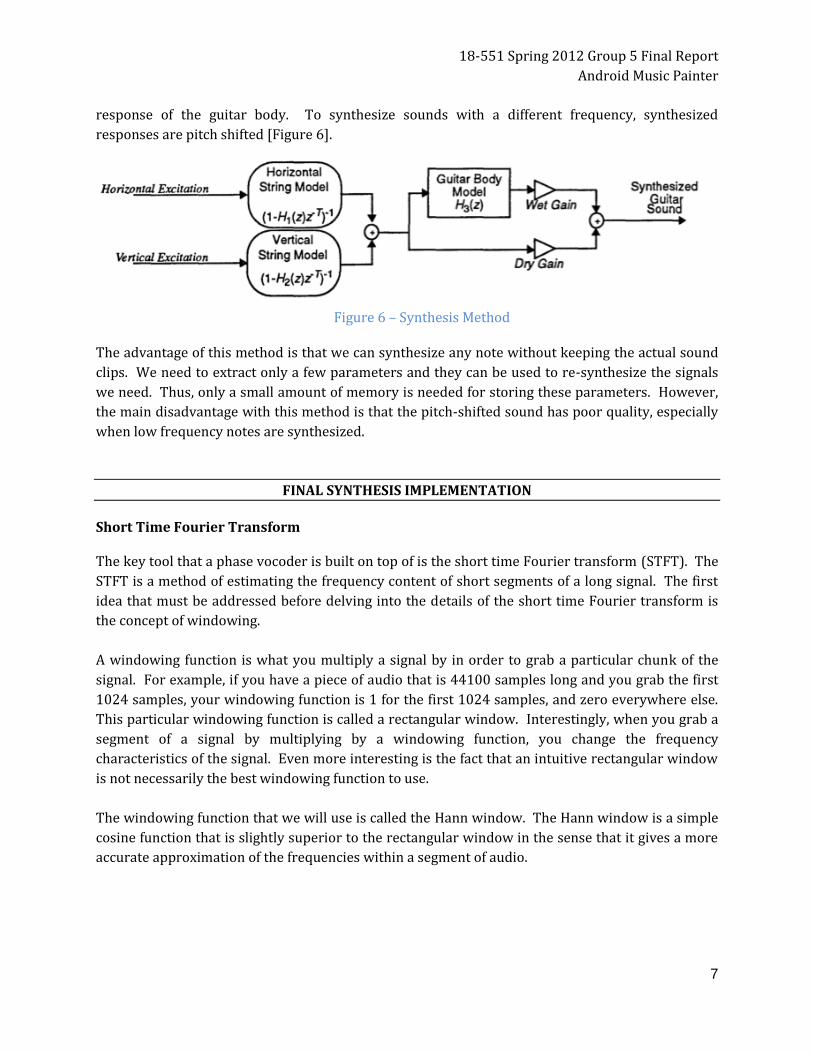
response of the guitar body. To synthesize sounds with a different frequency, synthesized
responses are pitch shifted [Figure 6].
The advantage of this method is that we can synthesize any note without keeping the actual sound
clips. We need to extract only a few parameters and they can be used to re-synthesize the signals
we need. Thus, only a small amount of memory is needed for storing these parameters. However,
the main disadvantage with this method is that the pitch-shifted sound has poor quality, especially
when low frequency notes are synthesized.
FINAL SYNTHESIS IMPLEMENTATION
Short Time Fourier Transform The key tool that a phase vocoder is built on top of is the short time Fourier transform (STFT). The
STFT is a method of estimating the frequency content of short segments of a long signal. The first
idea that must be addressed before delving into the details of the short time Fourier transform is
the concept of windowing.
A windowing function is what you multiply a signal by in order to grab a particular chunk of the
signal. For example, if you have a piece of audio that is 44100 samples long and you grab the first
1024 samples, your windowing function is 1 for the first 1024 samples, and zero everywhere else.
This particular windowing function is called a rectangular window. Interestingly, when you grab a
segment of a signal by multiplying by a windowing function, you change the frequency
characteristics of the signal. Even more interesting is the fact that an intuitive rectangular window
is not necessarily the best windowing function to use.
The windowing function that we will use is called the Hann window. The Hann window is a simple
cosine function that is slightly superior to the rectangular window in the sense that it gives a more
accurate approximation of the frequencies within a segment of audio.
Figure 6 – Synthesis Method
18-551 Spring 2012 Group 5 Final Report
Android Music Painter
8
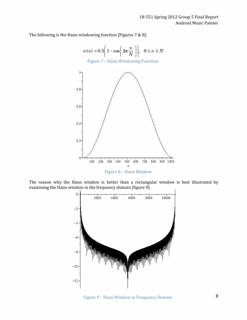
The following is the Hann windowing function [Figures 7 & 8]:
The reason why the Hann window is better than a rectangular window is best illustrated by examining the Hann window in the frequency domain [figure 9].
Figure 7 – Hann Windowing Function
Figure 8 – Hann Window
Figure 9 – Hann Window in Frequency Domain

18-551 Spring 2012 Group 5 Final Report
Android Music Painter
9
Note that the Hanning window is very close to a delta function in frequency, since it is close to 0
decibels at low frequencies and is negative at higher frequencies. This corresponds to being 1 at
low frequencies and close to zero everywhere else when the logarithm is not taken. We want the
windowing function we use to closely resemble a delta function in frequency because when we
multiply by a windowing function, we effectively perform a convolution in frequency, thus if we
want the frequency characteristics to be maintained, we need something that looks like a delta
function in frequency.
As can be seen below in figure 10, the side lobes of the rectangular window in the frequency
domain are not as small as those of the Hann window. Therefore, when computing the STFT of a
signal, the Hann window is closer to a delta function in frequency than the rectangular window. So,
when performing our STFT we will use the Hann window.
Now that we have discussed windowing, we focus on our implementation of the STFT. The STFT is
simply the process of taking the Fourier transform of a sequence of chunks from a signal. For
example, the STFT of an audio file could be taken by taking the Fourier transform of the first set of
1024 samples of the audio file, then the second set of 1024 samples, and then the third set of 1024
samples, and so on until there are no more samples in the audio file. Applying what we learned
about windowing functions, we know that the best way to obtain these sets of 1024 samples, in this
example, is to multiply by a Hann window. However, there is one more factor that must be taken
into consideration, namely the amount by which each segment we grab overlaps with the other
segments. In the example just stated, the frames of 1024 samples from the audio file do not
Figure 10 – Rectangular Window Frequency Domain Decibels

18-551 Spring 2012 Group 5 Final Report
Android Music Painter
10
overlap. Since our phase vocoder relies on interpolating frequencies between consecutive frames
in a signal, it would be better if each frame we grab from the original signal had something in
common with its adjacent frames. In particular, we want adjacent frames to overlap with one
another in the original signal. This can be achieved by taking the STFT in the following way: grab
1024 samples starting at the first sample, grab 1024 samples starting at the 257th sample, grab
1024 samples starting at the 513th sample, and so on. In this example, every frame of 1024
samples is offset from the previous frame by 128 samples, so each frame shares 75% of its samples
with its adjacent frames. Again, this overlap between adjacent frames is crucial, since it allows us to
interpolate between frames to extend the length of a signal with far greater accuracy than if
adjacent frames were chosen end to end, and did not overlap at all.
Note that the examples above use a frame size of 1024 and an offset of 256 between frames. These
are the same parameters that we decided to use in our implementation of the STFT. We chose a
frame size of 1024 because it strikes a good balance between speed, and the frequency resolution
required by the phase vocoder. Additionally, an offset size of 256 was chosen because it is
necessary to ensure correct reconstruction of a signal when we take the inverse STFT. The details
of this reconstruction will be discussed in the inverse STFT section.
(Note that the fast Fourier transform implementation we used was obtained from [4].)
Phase Vocoder Interpolation Now that we have discussed the STFT, we can show how it is used to extend the duration of a sound
clip without changing the frequency characteristics of the signal. This is done by taking the STFT of
the signal and then adding more frames to the STFT by interpolating between the frames we
created by doing the STFT. When we create extra frames to extend the length of the sound, there
are two things we need to worry about: the magnitude of each frequency in the interpolated frames
and the phase of each frequency in the interpolated frames. We can compute the magnitude of
each frequency in an interpolated frame by using linear interpolation between consecutive frames
in the STFT we just computed. However, computing the phase of each frequency is slightly more
complicated. The first step to computing the phases is to compute the interpolated frames in order
(from the beginning of the sound to the end of the sound). This computation is done by keeping a
buffer that accumulates the phase changes for each frequency. This phase accumulation process is
explained further through the following examples and formulas.
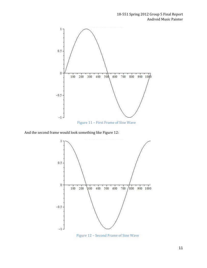
Suppose our signal is comprised of a pure sine wave. If we break our sine wave signal into a
sequence of 1024 sample frames that are offset from one another by 256 samples, then the first
frame would look something like figure 11:
18-551 Spring 2012 Group 5 Final Report
Android Music Painter
11
And the second frame would look something like Figure 12:
Figure 11 – First Frame of Sine Wave
Figure 12 – Second Frame of Sine Wave

18-551 Spring 2012 Group 5 Final Report
Android Music Painter
12
As you can see from the two figures above, the phase of the pure sine wave changes going from the
first to the second frame of a signal composed of a pure sine wave. This phase change is due to the
fact that there is a delay between the time when the first and second frame of the signal was
acquired. This shift in the phase can be described by the following formula:
timeDelayPhaseChange = (2 * Pi * hopSize) * frequencyBin / windowSize
where hopSize is the number of samples of delay between consecutive frames, and where
frequencyBin refers to the index of the frequency of interest in the Fourier transform. Time delay is
not the only thing that can cause the phase of frequencies between adjacent frames to differ,
another source of phase changes can be attributed to "frequency leakage". Consider a signal of
length 1024 comprised of a pure sine wave, if this sine wave is not one of the (1024/2 + 1) possible
frequencies captured by the Fourier transform of the signal, then the frequency spills over into the
closest frequency bins that the Fourier transform of the signal can capture. In addition to this
spillage the phase of the frequency bins that catch the spillage are affected as well. For example, if
there is a 1024 sample long pure sine wave that has a slightly higher frequency than the 10th
frequency bin of the Fourier transform, then the phase change in the 10th bin of the Fourier
transform between two consecutive frames is larger than the change in phase that can be attributed
to time delay. This phase change attributed to frequency leakage can be described by the following
formula:
frequencySpillPhaseChange = Phase of Second Frame - Phase of First Frame -
timeDelayPhaseChange
where "Phase of Second Frame" is the phase of the latter of the two frames used to construct the
interpolated frame and "Phase of First Frame" is the phase of the first of the two frames used to
construct the interpolated frame.
Both of these phase effects need to be accounted for when constructing an interpolated frame.
Incidentally, combining the two formulas above produces the change in phase between the
previous interpolated frame and the current interpolated frame:
phaseChangeBetweenInterplatedFrames = timeDelayPhaseChange +
frequencySpillPhaseChange = Phase of Second Frame - Phase of First Frame
As seen above, the phase change between two consecutive interpolated frames can simply be
reduced to the change in phase between the two frames used to create the newest interpolated
frame. Also note that this formula represents changes in phase, so (as mentioned earlier) if we
want to compute the actual phase for an interpolated frame, we must compute the interpolated
frames starting at the beginning of the sound, and then accumulate the phase changes as we create
the following interpolated frames for the sound.
18-551 Spring 2012 Group 5 Final Report
Android Music Painter
13
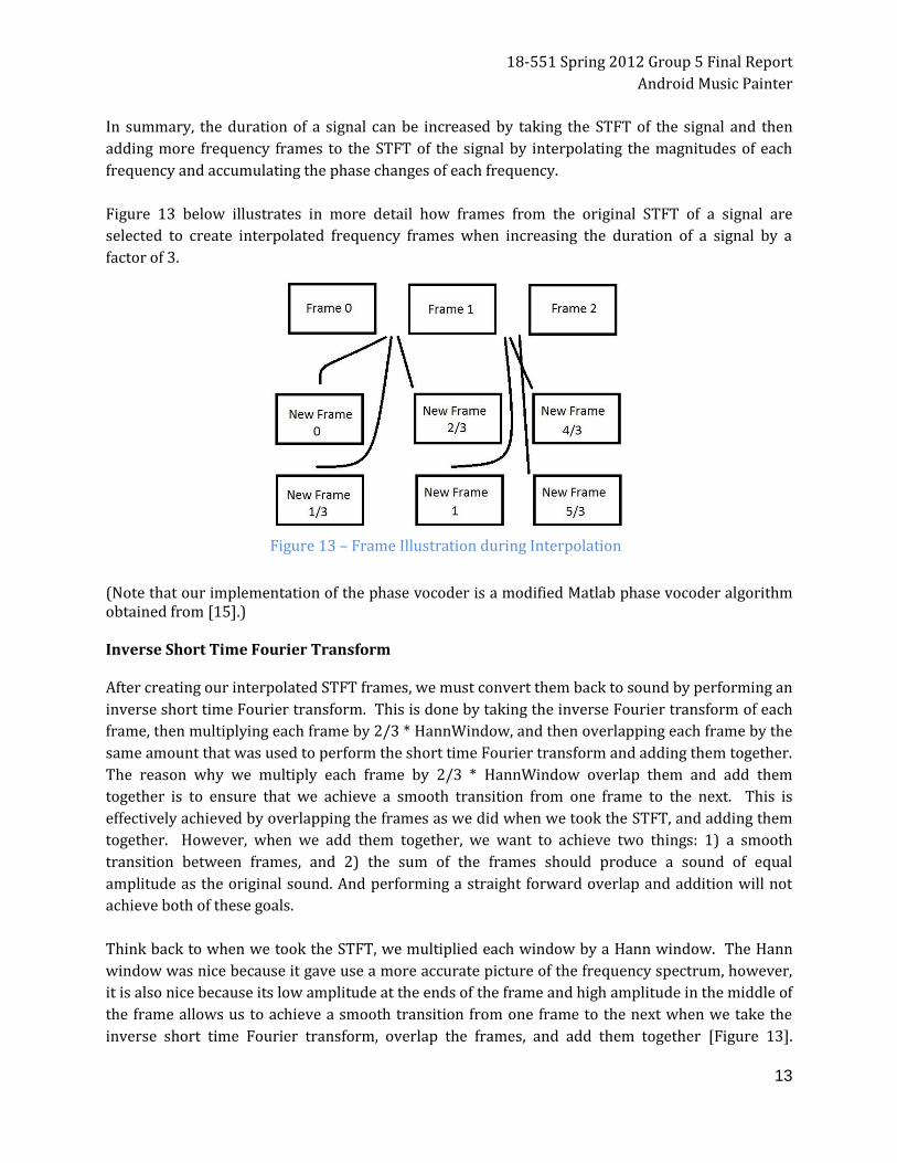
In summary, the duration of a signal can be increased by taking the STFT of the signal and then
adding more frequency frames to the STFT of the signal by interpolating the magnitudes of each
frequency and accumulating the phase changes of each frequency.
Figure 13 below illustrates in more detail how frames from the original STFT of a signal are
selected to create interpolated frequency frames when increasing the duration of a signal by a
factor of 3.
(Note that our implementation of the phase vocoder is a modified Matlab phase vocoder algorithm obtained from [15].) Inverse Short Time Fourier Transform After creating our interpolated STFT frames, we must convert them back to sound by performing an
inverse short time Fourier transform. This is done by taking the inverse Fourier transform of each
frame, then multiplying each frame by 2/3 * HannWindow, and then overlapping each frame by the
same amount that was used to perform the short time Fourier transform and adding them together.
The reason why we multiply each frame by 2/3 * HannWindow overlap them and add them
together is to ensure that we achieve a smooth transition from one frame to the next. This is
effectively achieved by overlapping the frames as we did when we took the STFT, and adding them
together. However, when we add them together, we want to achieve two things: 1) a smooth
transition between frames, and 2) the sum of the frames should produce a sound of equal
amplitude as the original sound. And performing a straight forward overlap and addition will not
achieve both of these goals.
Think back to when we took the STFT, we multiplied each window by a Hann window. The Hann
window was nice because it gave use a more accurate picture of the frequency spectrum, however,
it is also nice because its low amplitude at the ends of the frame and high amplitude in the middle of
the frame allows us to achieve a smooth transition from one frame to the next when we take the
inverse short time Fourier transform, overlap the frames, and add them together [Figure 13].
Figure 13 – Frame Illustration during Interpolation
18-551 Spring 2012 Group 5 Final Report
Android Music Painter
14
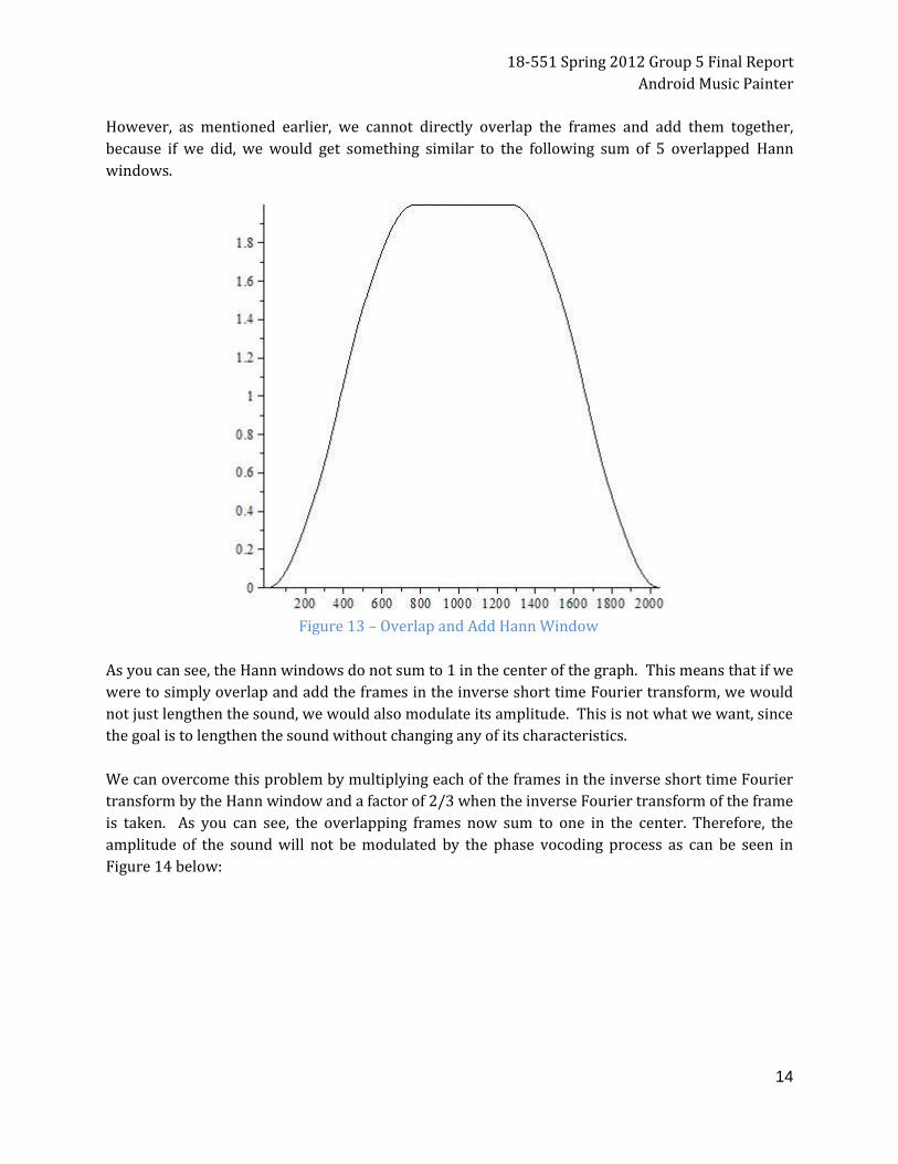
However, as mentioned earlier, we cannot directly overlap the frames and add them together,
because if we did, we would get something similar to the following sum of 5 overlapped Hann
windows.
As you can see, the Hann windows do not sum to 1 in the center of the graph. This means that if we
were to simply overlap and add the frames in the inverse short time Fourier transform, we would
not just lengthen the sound, we would also modulate its amplitude. This is not what we want, since
the goal is to lengthen the sound without changing any of its characteristics.
We can overcome this problem by multiplying each of the frames in the inverse short time Fourier
transform by the Hann window and a factor of 2/3 when the inverse Fourier transform of the frame
is taken. As you can see, the overlapping frames now sum to one in the center. Therefore, the
amplitude of the sound will not be modulated by the phase vocoding process as can be seen in
Figure 14 below:
Figure 13 – Overlap and Add Hann Window

18-551 Spring 2012 Group 5 Final Report
Android Music Painter
15
Therefore, the final step to stretching a signal in time without changing its frequency characteristics
is to perform an inverse short time Fourier transform, as described above, on the interpolated
frequency frames that were produced by the phase vocoding process.
Polyphase Structures for Sample Rate Conversion by a Non-Integer Factor
To synthesize each respective instrument’s sound at a given fundamental frequency, we needed to
resample samples of instrument’s sounds by a non-integer factor. While maintaining a reasonable
speed, we tried to synthesize sounds that sounded decent to the ear. To achieve this goal, we
considered naïve sampling rate conversion by L/M- by first interpolating by an integer factor L, and
then decimating by an integer factor of M. The naïve implementation is simple and it produces a
decent sound; however, the problem arising from this method is a slow computational speed and
memory problem. For example, if we need to synthesize an F4 (392 Hz) sound from a sample of E4
(329.63 Hz) note, we need to resample at a factor of 1.20 (6/5). We would first upsample by a
factor of 6 and then downsample by a factor of 5. By downsampling by a factor of 5, we throw away
some samples. This method is not efficient because we do computations on some samples that we
end up throwing away. In addition, upsampling by a factor of 6 requires a large memory space to
store intermediate values. Because of these reasons explained above, the naïve implementation is
not an appropriate approach to be used in a memory-limited machine like a tablet.
The second approach we considered was using linear interpolation for upsampling and just simply
dropping out samples for decimation. Although we can obtain a better speed with this method,
Figure 14 – Overlap Hann Window Multiplied by 2/3 Hann
18-551 Spring 2012 Group 5 Final Report
Android Music Painter
16
linear interpolation does not produce good quality sounds. Moreover, we still need to apply anti-
aliasing filters before we decimate. Since the filters are not applied at the stage with the lowest
sampling rate, the system is still not efficient.
Finally, we implemented a polyphase filter for sampling rate changing system. Aiming to optimize
by computing only samples that will be finally retained and applying a filter at the stage with lowest
sampling rate, polyphase structures can produce a decent sound at low computational cost.
Supposed we want to change a sampling rate of x[n] by a factor of L/M. Let h[n] be
a low pass filter with a cut off of
Define
Since is periodic with period L in m domain, it can be pre-computed and then selected
according to m. Then, y[m], x[n] sampled at L/M times the original sampling rate is as follows:
Although this polyphase approach is more complicated, it produces good quality results with
sufficient speed. For this exact reason, we implemented a polyphase filter in Java in our application.
GUI IMPLEMENTATION
Main Layout The main form of input for our project is the user’s touch interaction with the Android tablet and
therefore, the GUI was programmed and designed to make the application’s functions intuitive and
easy to learn for any user. To set up the main screen, a RelativeLayout is set up with with the
application title at the top and a HorizontalScrollView underneath. Along the sides of the main
layout are ImageView buttons that represent the instruments the user may use. The layout was set
up this way so that the user would be able to easily find the instrument options upon starting the
application. A HorizontalScrollView was used as the main layout because the x-axis was used to
represent time (in the music) while the y-axis represented frequency. The HorizontalScrollView
allowed us to implement a scrolling function to increase the time (x-axis) as needed for the user.
However, it was found that a HorizontalScrollView only allows for one child view within the view.
Therefore, a single RelativeLayout was added to the HorizontalScrollView because RelativeLayouts
allow for multiple children. From there, the user would be able to add as many music notes to the
view as they want, because the music notes are represented as their own class of views (described
below). The main layout set up is pictured below in Figures 15 and 16:

18-551 Spring 2012 Group 5 Final Report
Android Music Painter
17
Music Notes After implementing the main layout, the next focus was creating a view for the music notes so that
they could be added to the overall RelativeLayout view. When it came to designing the notes, we
wanted the user to be able to easily see each note they added on the screen while at the same time,
also be able to know the features for each note. More specifically, each note contains the following
features: instrument type, frequency, time (in music), length (of the specific note), and string. To
make it easier to keep track of these parameters, a GuitarGroup class was created, which extends
the LinearLayout class. GuitarGroup objects keep track of all the given parameters and display
them as TextViews on the object image. Next, to make it easier for the user to distinguish between
Figure 15 – Overall Application Layout Set Up
Figure 16 – Overall Application Layout on the Tablet
18-551 Spring 2012 Group 5 Final Report
Android Music Painter
18
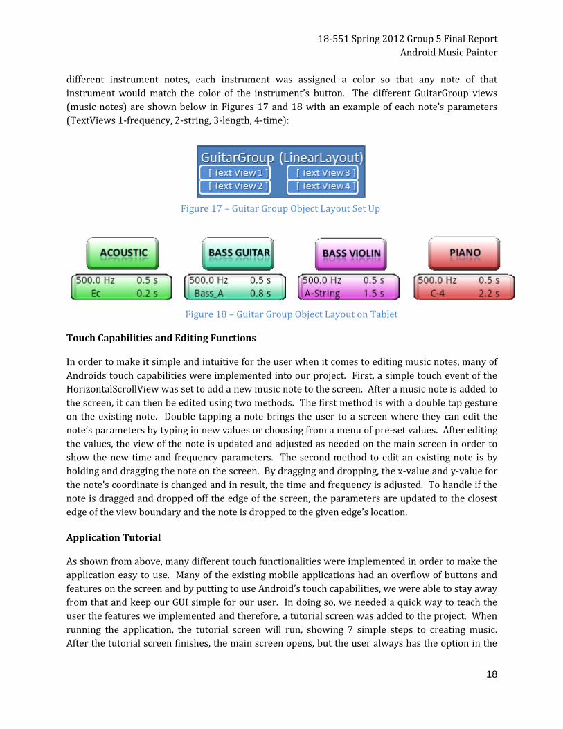
different instrument notes, each instrument was assigned a color so that any note of that
instrument would match the color of the instrument’s button. The different GuitarGroup views
(music notes) are shown below in Figures 17 and 18 with an example of each note’s parameters
(TextViews 1-frequency, 2-string, 3-length, 4-time):
Touch Capabilities and Editing Functions In order to make it simple and intuitive for the user when it comes to editing music notes, many of
Androids touch capabilities were implemented into our project. First, a simple touch event of the
HorizontalScrollView was set to add a new music note to the screen. After a music note is added to
the screen, it can then be edited using two methods. The first method is with a double tap gesture
on the existing note. Double tapping a note brings the user to a screen where they can edit the
note’s parameters by typing in new values or choosing from a menu of pre-set values. After editing
the values, the view of the note is updated and adjusted as needed on the main screen in order to
show the new time and frequency parameters. The second method to edit an existing note is by
holding and dragging the note on the screen. By dragging and dropping, the x-value and y-value for
the note’s coordinate is changed and in result, the time and frequency is adjusted. To handle if the
note is dragged and dropped off the edge of the screen, the parameters are updated to the closest
edge of the view boundary and the note is dropped to the given edge’s location.
Application Tutorial As shown from above, many different touch functionalities were implemented in order to make the
application easy to use. Many of the existing mobile applications had an overflow of buttons and
features on the screen and by putting to use Android’s touch capabilities, we were able to stay away
from that and keep our GUI simple for our user. In doing so, we needed a quick way to teach the
user the features we implemented and therefore, a tutorial screen was added to the project. When
running the application, the tutorial screen will run, showing 7 simple steps to creating music.
After the tutorial screen finishes, the main screen opens, but the user always has the option in the
Figure 17 – Guitar Group Object Layout Set Up
Figure 18 – Guitar Group Object Layout on Tablet

18-551 Spring 2012 Group 5 Final Report
Android Music Painter
19
menu to return and refer back to it. A screen shot of the finished tutorial screen is displayed below
in Figure 19:
Menu Options Finally, we utilized the built in Android options menu and added six options for our user:
Back to Tutorial The user can return back to the tutorial screen in case they need a reminder of how to complete a certain task.
Play Music The user can have their music synthesized and played back to them.
Reset Screen The user can clear their current screen and start over.
Save Music The user can save the music they have created on the current screen.
Load Music The user can reset their screen and load what was last saved onto the screen.
Exit Application The user can exit the application.
Figure 19 – Application Tutorial Screen

18-551 Spring 2012 Group 5 Final Report
Android Music Painter
20
GUI Resources Putting together the Android functionalities and the graphics for the GUI required the use of not
only Android programming, but also PowerPoint and Gimp to create the images used in our
application. Along with these resources, Stack Overflow was also a major source of information and
assistance when it came to debugging any Android code [17].
GUI AND CODE INTEGRATION
The GUI and synthesis code was integrated through the use of the model, view, controller
abstraction. The model view controller software design pattern breaks user input and processing
into three basic parts: the model is the data structure which holds the information used for
processing, the controller is the code that interfaces with and updates the model, and the view is
the GUI interface that the user interacts with. Our implementation encapsulated the functionality of
a view and a controller in a view class, which was displayed to the user and represents a block of
sound. This view/controller class then holds a reference to an actual sound object, which stores all
the information relevant to the sound being generated and handles the synthesis of the sound.
Furthermore, these sound objects are stored in a sound queue object, which handles overlapping
and adding the individual notes that the user specifies to create the final musical piece. The sounds
in these queues are stored in the order in which the sounds begin playing in the song. This sorting
is done quickly as the user adds and deletes notes through the use of a min heap.
When the user is ready to synthesize, the application simply iterates through all the elements in the
queue by pulling the song with the smallest starting time out the heap, assigning a thread to
synthesize it, and then overlapping and adding the sounds in the order that they appear in the song.
Figure 20 illustrates this process:
Figure 20 – GUI and Code Integration Process

18-551 Spring 2012 Group 5 Final Report
Android Music Painter
21
Some improvements for future integration of the GUI and synthesis could leverage the fact that
(from the perspective of the tablet) there are large chunks of time between successive user inputs.
So, it would be possible to artificially increase the speed of the application by synthesizing notes for
the song in the background as the user adds notes to the song.
OPTIMIZATION
There were primarily seven ways in which we improved the performance of our instrument synthesizer. 1) Structure of Arrays vs. Array of Structures
Our initial implementation of the STFT and phase vocoder was done using complex number objects.
Thus, our STFT routine took an array of floats and returned an array of complex numbers. Using a
complex number object allowed us to easily encapsulate complex addition, multiplication, and
subtraction cleanly and understandably, however this came with considerable performance costs.
This high performance cost is primarily due to the process of creating an object in java. Every time
an object is created in java it is allocated on the heap. This is problematic because if we have an
array of complex numbers, each complex number must be individually allocated on the heap. And
heap operations are typically very expensive. To put the cost of heap allocations in perspective,
approximately one million heap allocations would have to be made to process a 3 second sound and
each heap allocation likely costs the same as 100 - 1000 floating point operations or more.
This problem is not new, and many people call our first attempt at the implementation an Array of
Structures approach. One easy work around for this problem was to use a Structure of Arrays
approach. This is where an array of objects is replaced with many parallel arrays of primitives.
Where the kth index into each array represents the attributes of the kth object. In the context of
our project, this meant exchanging complex number objects for two arrays (one array for the real
components and one array for the imaginary components). This approach allows us to avoid the
large cost of millions of heap allocations because arrays of primitives are allocated as one
contiguous block of memory on the heap. The performance benefit obtained by moving algorithms
from an Array of Structures approach to a Structure of Arrays approach made synthesis of a note
that previously look tens of minutes synthesize only seconds to synthesize. This Structure of Arrays
approach was also facilitated by the excellent implementation of the bit reversal FFT we used at
www.jtransform.org
2) Array Allocation
Another simple optimization relevant to the Structure of Arrays approach was the minimization of
array allocations. It is common to have a temporary buffer which is used for calculations and that is
never used again, particularly in the implementation of polyphase filters. In our original
implementation of polyphase filters, we allocated these temporary buffers within a loop. Simply
moving these allocations outside of the loop, and saving the memory used by the temporary buffer
improved performance by another factor of 2. Note that this dramatic speed improvement was due

18-551 Spring 2012 Group 5 Final Report
Android Music Painter
22
to the same reasons that caused the Structure of Arrays approach to synthesis much faster.
Specifically, all array allocations in java are done on the heap, so reallocating arrays within loops is
very expensive.
3) Multi-Threading
Multi-Threading also improved the speed of our sound synthesizer. The synthesis of individual
notes was not multi-threaded, instead the synthesis of several instrument notes were done in
parallel. Thus this does not provide a speed improvement for users who are synthesizing single
long notes, however, since most musical compositions are comprised of many short notes, our
parallelization of the synthesizer improves synthesis by a factor of 2.
4) Phase Unwrapping
Most phase vocoder implementations require phase unwrapping to properly stretch a signal in time
because they stretch the signal in time by increasing the hop size between adjacent frames in an
STFT to be larger than the original hop size used to compute the STFT of the signal. Since our phase
vocoder implementation uses interpolation as the primary means to increase the length of the
signal, phase unwrapping is unnecessary. In fact the only phase information needed for our
implementation of the phase vocoder is the difference change in phase between frames used to
create interpolated frames, and a buffer that accumulates phase changes for each frequency.
5) Caching STFT
Our original implementation of the synthesizer recomputed the STFT of the sampled notes used for
synthesis every time we synthesized a note. We removed this additional computation by simply
caching the STFT or a sample note after it was computed once. Performing this simple caching
improved performance approximately by a factor of 1.15.
6) Floats vs. Doubles
Using floats instead of doubles as our data primitive also provided a performance improvement,
since many Android devices have native floating point capabilities, while double precision
arithmetic must be implemented in software to some degree. Ultimately, switching over to floats
improved performance approximately by a factor of 1.10.
7) Overlap Add
After synthesizing the notes that we wish to play we must add them together appropriately.
Originally we kept a list of currently playing sounds, and added the currently playing sounds
together one sample at a time to produce the final output sound. This was relatively costly because
it required several function calls and condition checks to be executed for every sample. Now we
simply grab the sound with the smallest starting index, find the appropriate offset in the final sound
array, and add the sound into the final output array all in one shot (as opposed to one sample at a
time). This resulted in a speed improvement factor of approximately 1.1.

18-551 Spring 2012 Group 5 Final Report
Android Music Painter
23
SCHEDULE AND DIVISION OF LABOR
Week Milestone
Feb 12 - Feb 19 Background research, determine basic features for the application and what techniques to use
Feb 19 - Feb 26 Research on instrument synthesis
Feb 26 - Mar 4 Implement guitar analysis/synthesis in MATLAB
Mar 4 - Mar 11 Continue working on guitar analysis/synthesis in MATLAB, basic GUI
Mar 11 - Mar 18 Spring Break
Mar 18 - Mar 25 Implement guitar synthesis in Java, work on sound queue, basic GUI
Mar 25 - Apr 1 Work on phase vocoder, pitch shift by sampling rate conversion, implement additional features in the GUI including dragging notes and scrolling left and right
Apr 1 - Apr 8 Speed up phase vocoder, integrate the developed algorithm with the GUI
Apr 8 - Apr 15 Code Optimization, speed up pitch shifting, add a piano, violin, and bass guitar
Apr 15 - Apr 22 Create a tutorial Screen, additional GUI features including saving and loading
Apr 22 - Apr 29 Work on final report/demo
While the entire team worked on each milestone listed above, we each took charge on a specific
portion of the project. These task responsibilities were divided in such a way that each person
focused on the completion of any tasks in the schedule that fell under their respective category. If
their task was finished early, then they assisted the rest of the team if necessary or they moved
forward to their next task in the schedule. The task responsibilities were divided in the following
fashion:
Kelly – GUI/Android Functionalities, Graphics
Tim – Code Optimization, Multithreading, Finding Bottlenecks
Nattamon – Synthesis: Phase Vocoder, Resampling
Figure 21 – Task Timeline

18-551 Spring 2012 Group 5 Final Report
Android Music Painter
24
DEMO
For our final demo, users were able to play around with our application and create music, despite
what background knowledge they had in music creation. The application was presented to the user
starting from the tutorial screen, where they learned about the application’s features. Then, having
learned about the application’s functionalities in the tutorial, the user had the freedom create
music, adding and editing notes as they pleased. When finished, they played their composition.
Aside from letting people create music on their own, we also gave a quick presentation of a
previously saved music screen. Our group put together a screen of music notes that we thought
sounded interesting and showed a good example of what our application could do and what sort of
music it could create, even though none of us have any background in music creation. This showed
the audience how simple and easy to use our application is and the fun results that users can get
from it.
FUTURE WORK
Addition of Instruments
Currently, there are four instruments available for the user to use. With more time, additional
instruments can easily be implemented to the application so that the user can have a greater range
of choices and diversity with the end result of their work.
Save to Database
In the present state, the application allows the user to save one screen and load it back up
whenever they want. Adding in a database to store multiple screens will make the application more
useful for the user, as they will be able to essentially save files under names and load them to edit or
play later on.
Write to File
While our application provides a single saving screen feature, it takes time to open the application
and load up the saved music. With some work, a valuable feature of writing out the sound to a file
would be easily implemented. Then, a user would be able to save their music to an actual file and
play it without having to open the music painter.
Edit Existing Music
The last feature that was thought about but cut due to feasibility given time is the idea of adding
music to existing music or sound files. With this feature, the user would be able to load in already
existing files, whether it is sound files they created or actual song files, and then add music notes to
it. This would be nice as it is a feature that many music synthesis/editing software have.
18-551 Spring 2012 Group 5 Final Report
Android Music Painter
25
REFERENCES
[1] "AMG: Ambient Music Generator." Creative Applications Network. CreativeApplications, 19 Jan. 2010. Web. 18 Feb. 2012. <http://www.creativeapplications.net/iphone/amg-ambient-music-generator-iphone-sound>. [2] "Jasuto." Jasuto: A Modular Synth for iPhone and VST. Ed. Chris Wolfe. N.p., 30 Mar. 2009. Web. 18 Feb. 2012. <http://www.jasuto.com/site>. [3] Stahl, Marco. "Android Synthesizer for Android." Hitsquad Music Software. HItsquad, 24 Sept. 2010. Web. 18 Feb. 2012. <http://www.hitsquad.com/smm/programs/Android_Synthesizer>. [4] “JTransform” <http://sites.google.com/site/piotrwendykier/software/jtransforms>
[5] Steven W. Smith. “Audio Processing.” <www.dispguide.com>. [6] Gaungji Shi, Shanechi, M.M., Arabi P. “On the importance of phase in human speech recognition.” Sept. 2006 <Audio, Speech, and Language Processing> [7] Radu Balan. “On Signal Reconstruction from Its Spectrogram.” [8] Allen, Jont. "A unified Approach to short time Fourier analysis and synthesis." *Preceedings of the IEEE*. 65.11 (1977): n. page. Web. 21 Feb. 2012. <http://cronos.rutgers.edu/~lrr/lrrpapers/122_unified_approach_to_STFT.pdf>. [9] Johnson, Don. "Spectrograms." *Connexions*. N.p., 08 AUG 2009. Web. 21 Feb 2012. <http://cnx.org/content/m0505/latest>. [10] "Musical Analysis and Synthesis." . N.p., n.d. Web. 21 Feb 2012. <http://amath.colorado.edu/pub/matlab/music/Petersen04CMJ.pdf>. [11] Patrick, Bastein. "Pitch Shifting and Voice Transformation Technique." N.p., n.d. Web. 21 Feb 2012. <http://dsp-book.narod.ru/Pitch_shifting.pdf>. [12] “Animoog for iPhone.” Moog. Moog Music Inc., 2012. Web. 22 Feb 2012. <http://moogmusic.com/products/apps/animoog-iphone>. [13] Lim, Jae S. Advanced Topics in Signal Processing. 3. [14] Bradley, Kevin. “Synthesis of an Acoustic Guitar with a Digital String Model and Linear Prediction“.” 1995. [15] "Phase Vocoder." <http://labrosa.ee.columbia.edu/matlab/pvoc>. [16] "Fast Fourier Transform" <http://introcs.cs.princeton.edu/java/97data/FFT.java.html>. [17] “Stack Overflow” <http://www.stackoverflow.com>.