1734-um020a-en-e point i/o 4 channel io-link master … io 4 channel io-link master...
TRANSCRIPT

User Manual
(Catalog Number 1734-4IOL)
POINT I/O 4 Channel IO-Link Master Module

Important User InformationSolid-state equipment has operational characteristics differing from those of electromechanical equipment. Safety Guidelines for the Application, Installation and Maintenance of Solid State Controls (Publication SGI-1.1 available from your local Rockwell Automation sales office or online at http://www.rockwellautomation.com/literature/) describes some important differences between solid-state equipment and hard-wired electromechanical devices. Because of this difference, and also because of the wide variety of uses for solid-state equipment, all persons responsible for applying this equipment must satisfy themselves that each intended application of this equipment is acceptable.
In no event will Rockwell Automation, Inc. be responsible or liable for indirect or consequential damages resulting from the use or application of this equipment.
The examples and diagrams in this manual are included solely for illustrative purposes. Because of the many variables and requirements associated with any particular installation, Rockwell Automation, Inc. cannot assume responsibility or liability for actual use based on the examples and diagrams.
No patent liability is assumed by Rockwell Automation, Inc. with respect to use of information, circuits, equipment, or software described in this manual.
Reproduction of the contents of this manual, in whole or in part, without written permission of Rockwell Automation, Inc., is prohibited.
Throughout this manual, when necessary, we use notes to make you aware of safety considerations..
Allen-Bradley, Rockwell Automation, POINT I/O, POINTBus, RSLogix, Studio 5000, RSNetWorx, and TechConnect are trademarks of Rockwell Automation, Inc.
Trademarks not belonging to Rockwell Automation are property of their respective companies.
WARNING: Identifies information about practices or circumstances that can cause an explosion in a hazardous environment, which may lead to personal injury or death, property damage, or economic loss.
IMPORTANT Identifies information that is critical for successful application and understanding of the product.
ATTENTION: Identifies information about practices or circumstances that can lead to personal injury or death, property damage, or economic loss. Attentions help you identify a hazard, avoid a hazard, and recognize the consequence
WARNING: Labels may be on or inside the equipment, for example, a drive or motor, to alert people that dangerous voltage may be present.
WARNING: Labels may be on or inside the equipment, for example, a drive or motor, to alert people that surfaces may reach dangerous temperatures.

Table of Contents
Preface Purpose of This Manual . . . . . . . . . . . . . . . . . . . . . . . . . . . . . . . . . . . . . . . . . . . . 7Who Should Use This Manual . . . . . . . . . . . . . . . . . . . . . . . . . . . . . . . . . . . . . . 7Related Publications. . . . . . . . . . . . . . . . . . . . . . . . . . . . . . . . . . . . . . . . . . . . . . . . 8
Chapter 1
Introduction About This Chapter. . . . . . . . . . . . . . . . . . . . . . . . . . . . . . . . . . . . . . . . . . . . . . . . 9About the IO-Link Master Module . . . . . . . . . . . . . . . . . . . . . . . . . . . . . . . . . . 9
Product Description . . . . . . . . . . . . . . . . . . . . . . . . . . . . . . . . . . . . . . . . . . . . 9Modes of Usage . . . . . . . . . . . . . . . . . . . . . . . . . . . . . . . . . . . . . . . . . . . . . . . . . . . . 9
POINT I/O 4 Channel IO-Link Master - IO-Link Mode. . . . . . . . 10POINT I/O 4 Channel IO-Link Master - Standard Digital Input or Standard Digital Output Mode . . . . . . . . . . . . . . . . . . . . . . . . . . . . . . . . 10
Quick Start - Prepare the Module to Work on EtherNet/IP . . . . . . . . . 11
Chapter 2
Install the POINT I/O 4 Channel IO-Link Master Module
About This Chapter. . . . . . . . . . . . . . . . . . . . . . . . . . . . . . . . . . . . . . . . . . . . . . 13Environment and Enclosure . . . . . . . . . . . . . . . . . . . . . . . . . . . . . . . . . . . 13Preventing Electrostatic Discharge . . . . . . . . . . . . . . . . . . . . . . . . . . . . 14
Install the Mounting Base. . . . . . . . . . . . . . . . . . . . . . . . . . . . . . . . . . . . . . . . . 15Install the Module. . . . . . . . . . . . . . . . . . . . . . . . . . . . . . . . . . . . . . . . . . . . . . . . 15Install the Removable Terminal Block . . . . . . . . . . . . . . . . . . . . . . . . . . . . . 17Remove a Mounting Base . . . . . . . . . . . . . . . . . . . . . . . . . . . . . . . . . . . . . . . . . 17Wire the Modules . . . . . . . . . . . . . . . . . . . . . . . . . . . . . . . . . . . . . . . . . . . . . . . . 18
Chapter 3
Add the POINT I/O 4 Channel IO-Link Master Module on an EtherNet/IP Network
About This Chapter. . . . . . . . . . . . . . . . . . . . . . . . . . . . . . . . . . . . . . . . . . . . . . 21Install the POINT I/O 4 Channel IO-Link Master Add-On Profile . . 21Add a POINT I/O 4 Channel IO-Link Master Module to Studio 5000 . . . . . . . . . . . . . . . . . . . . . . . . . . . . . . . . . . . . . . . . . . . . . . . . . . . . . 24
IO-Link Tag Elements . . . . . . . . . . . . . . . . . . . . . . . . . . . . . . . . . . . . . . . . 28I/O Tags. . . . . . . . . . . . . . . . . . . . . . . . . . . . . . . . . . . . . . . . . . . . . . . . . . . . . 29Configuration Data. . . . . . . . . . . . . . . . . . . . . . . . . . . . . . . . . . . . . . . . . . . 29
Chapter 4
Configure the POINT I/O 4 Channel IO-Link Master as IO-Link Master Using the Studio 5000 Add-on Profile
About This Chapter. . . . . . . . . . . . . . . . . . . . . . . . . . . . . . . . . . . . . . . . . . . . . . 31User Roles . . . . . . . . . . . . . . . . . . . . . . . . . . . . . . . . . . . . . . . . . . . . . . . . . . . . . . . 31IO-Link Device Integration Levels. . . . . . . . . . . . . . . . . . . . . . . . . . . . . . . . . 32Configure Channel Mode. . . . . . . . . . . . . . . . . . . . . . . . . . . . . . . . . . . . . . . . . 33Configure IO-Link Devices . . . . . . . . . . . . . . . . . . . . . . . . . . . . . . . . . . . . . . . 34Register an IODD file . . . . . . . . . . . . . . . . . . . . . . . . . . . . . . . . . . . . . . . . . . . . 34
Rockwell Automation Publication 1734-UM020A-EN-E - September 2015 3

Table of Contents
Add an IO-Link Device . . . . . . . . . . . . . . . . . . . . . . . . . . . . . . . . . . . . . . . . . . . 36Change IO-Link Channel Configuration. . . . . . . . . . . . . . . . . . . . . . . . . . . 37Configure IO-Link Device Parameters Using the Add-on Profile . . . . . 39
IO-Link Device Parameter Behavior. . . . . . . . . . . . . . . . . . . . . . . . . . . . 42Manage Parameter Differences Between IO-Link Devices and Controller . . . . . . . . . . . . . . . . . . . . . . . . . . . . . . . . . . . . . . . . . . . . . . . . . . . 43Add a Generic IO-Link Device . . . . . . . . . . . . . . . . . . . . . . . . . . . . . . . . . . . . 44Configure IO-Link Device Parameters Using Message Instructions . . . 46
About the IO-Link Device Parameter Object . . . . . . . . . . . . . . . . . . . 46Create a Message Instruction for the IO-Link Device . . . . . . . . . . . . 46Locate the Parameter Index or Subindex Value in the IODD File . 48
Chapter 5
Configure the POINT I/O 4 Channel IO-Link Master Module as Standard Digital Input or Output Using the Studio 5000 Add-on Profile
About This Chapter . . . . . . . . . . . . . . . . . . . . . . . . . . . . . . . . . . . . . . . . . . . . . . 49Configure the Module as Standard Digital Input Using the Configuration Tab . . . . . . . . . . . . . . . . . . . . . . . . . . . . . . . . . . . . . . . . . . . . . . . 49Configure the Module as Standard Digital Output Using the Fault/Program Action Tab . . . . . . . . . . . . . . . . . . . . . . . . . . . . . . . . . . . . . . . . 50
Appendix A
Connected Data Mapping About This Appendix. . . . . . . . . . . . . . . . . . . . . . . . . . . . . . . . . . . . . . . . . . . . . 53Communicate with the Module . . . . . . . . . . . . . . . . . . . . . . . . . . . . . . . . . . . 53
Appendix B
Supported Events About This Appendix. . . . . . . . . . . . . . . . . . . . . . . . . . . . . . . . . . . . . . . . . . . . . 55IO-Link Master Module Events . . . . . . . . . . . . . . . . . . . . . . . . . . . . . . . . . . . 55
Querying the Events from the master to view 25 most recent events . . . . . . . . . . . . . . . . . . . . . . . . . . . . . . . . . . . . . . . . . . . . . . . . . 55IO-Link Master Event Codes . . . . . . . . . . . . . . . . . . . . . . . . . . . . . . . . . . 56Event Count . . . . . . . . . . . . . . . . . . . . . . . . . . . . . . . . . . . . . . . . . . . . . . . . . 56Event Qualifier . . . . . . . . . . . . . . . . . . . . . . . . . . . . . . . . . . . . . . . . . . . . . . . 57
Recent Events Controller Tag View . . . . . . . . . . . . . . . . . . . . . . . . . . . . . . . . 57
Appendix C
Troubleshooting About This Appendix. . . . . . . . . . . . . . . . . . . . . . . . . . . . . . . . . . . . . . . . . . . . . 59About Module Diagnostics . . . . . . . . . . . . . . . . . . . . . . . . . . . . . . . . . . . . . . . . 59Interpret LED Indicators . . . . . . . . . . . . . . . . . . . . . . . . . . . . . . . . . . . . . . . . . 60Troubleshooting Scenarios . . . . . . . . . . . . . . . . . . . . . . . . . . . . . . . . . . . . . . . . 61
Second Data I/O connection rejected . . . . . . . . . . . . . . . . . . . . . . . . . . 61Controller goes to fault when enabling/disabling Unicast . . . . . . . . 61
4 Rockwell Automation Publication 1734-UM020A-EN-E - September 2015

Table of Contents
Generic device with zero length input and output is accepted by the Add-on Profile . . . . . . . . . . . . . . . . . . . . . . . . . . . . . . . . . . . . . . . . . . . . . . . 61The ChxMostRecentEvent.EventSequenceCount is an unsigned value . . . . . . . . . . . . . . . . . . . . . . . . . . . . . . . . . . . . . . . . . . . . . . . 62
Rockwell Automation Publication 1734-UM020A-EN-E - September 2015 5

Table of Contents
Notes:
6 Rockwell Automation Publication 1734-UM020A-EN-E - September 2015

Preface
Purpose of This Manual This manual describes how to install, configure, and troubleshoot your POINT I/O™ IO-link Master module.
The POINT I/O 4 Channel IO-Link Master module can only be used in EtherNet/IP systems. Refer to EtherNet/IP publications in addition to this manual.
When using the POINT I/O 4 Channel IO-Link Master module with a communication adapter, use this manual in conjunction with the user manual for the adapter you are using as shown in the following table.
Who Should Use This Manual
This manual is intended for qualified personnel. You should be familiar with Studio 5000®, EtherNet/IP Network, and IO-Link terminology. If you do not qualify, refer to your software documentation or online help before attempting to use these modules.
When Using POINT I/O Modules on This Network
Refer to Publication for
Catalog No. Publication No.
EtherNet/IP network EtherNet/IP adapter 1734-AENT/B 1734-UM018
EtherNet/IP redundant network EtherNet/IP dual port adapter
1734-AENTR/B 1734-UM017

Preface
Related Publications Refer to this table for a list of related POINT I/O products and documentation. The publications are available from http://literature.rockwellautomation.com/. For specification and safety certification information, refer to the installation instructions.
Resource Description
POINT I/O 4 Channel IO-Link Master
POINT I/O 4 Channel IO-Link Master Installation Instructions, publication 1734-IN043
Provides installation information and wiring diagrams for the 1734-4IOL module.
POINT I/O 4 Channel IO-Link Master Release Notes, publication 1734-RN024
Release notes for the 1734-4IOL module
Communication Devices
1734 POINT I/O EtherNet/IP Adapter Installation Instructions, publication 1734-IN042
Provides installation information about 1734-AENT, Series B adapters.
1734 POINT I/O Dual Port EtherNet/IP Adapter, publication 1734-IN041 Provides installation information about 1734-AENTR, Series B adapters.
POINT I/O EtherNet/IP Adapter Module User Manual, publication 1734-UM018
Describes how to use 1734-AENT, Series B adapters.
POINT I/O and ArmorPOINT I/O Dual Port EtherNet/IP Adapters User Manual, publication 1734-UM017
Describes how to use 1734-AENTR, Series B adapters.
Power Supplies, Wiring Base Assemblies, Miscellaneous
Field Potential Distributor Installation Instructions, publication 1734-IN059 Provides installation information about 1734-FPD distributors.
POINT I/O 24V dc Expansion Power Supply Installation Instructions, publication 1734-IN058
Provides installation information about 1734-EP24DC power supplies.
POINT I/O 120/240V ac Expansion Power Supply Installation Instructions, publication 1734-IN017
Provides installation information about 1734-EPAC power supplies.
POINT I/O Common Terminal Module Installation Instructions, publication 1734-IN024
Provides installation information about 1734-CTM modules.
POINT I/O Voltage Terminal Module Installation Instructions, publication 1734-IN024
Provides installation information about 1734-VTM modules.
POINT I/O Wiring Base Assembly Installation Instructions, publication 1734-IN511
Provides installation information about 1734-TB and 1734-TBS assemblies.
POINT I/O Wiring Base Assembly Installation Instructions, publication 1734-IN013
Provides installation information about 1734-TB3 and 1734-TB3S assemblies.
POINT I/O One-piece Wiring Base Assembly Installation Instructions, publication 1734-IN028
Provides installation information about 1734-TOP, 1734-TOPS, 1734-TOP3 and 1734-TOP3S assemblies.
Industrial Automation Wiring and Grounding Guidelines, publication 1770-4.1
Detailed information on proper wiring and grounding techniques.
8 Rockwell Automation Publication 1734-UM020A-EN-E - September 2015
Chapter 1
Introduction
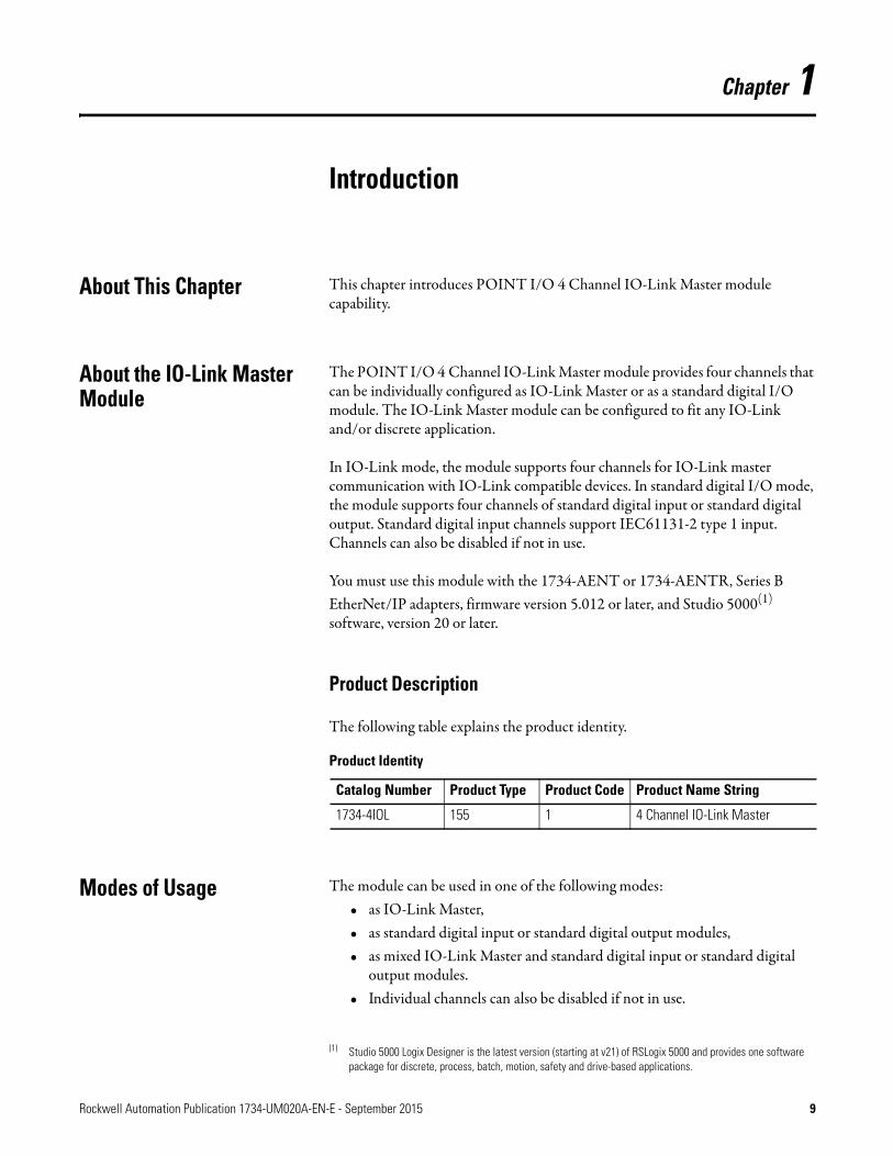
About This Chapter This chapter introduces POINT I/O 4 Channel IO-Link Master module capability.
About the IO-Link Master Module
The POINT I/O 4 Channel IO-Link Master module provides four channels that can be individually configured as IO-Link Master or as a standard digital I/O module. The IO-Link Master module can be configured to fit any IO-Link and/or discrete application.
In IO-Link mode, the module supports four channels for IO-Link master communication with IO-Link compatible devices. In standard digital I/O mode, the module supports four channels of standard digital input or standard digital output. Standard digital input channels support IEC61131-2 type 1 input. Channels can also be disabled if not in use.
You must use this module with the 1734-AENT or 1734-AENTR, Series B EtherNet/IP adapters, firmware version 5.012 or later, and Studio 5000(1) software, version 20 or later.
Product Description
The following table explains the product identity.
Modes of Usage The module can be used in one of the following modes:• as IO-Link Master,• as standard digital input or standard digital output modules,• as mixed IO-Link Master and standard digital input or standard digital
output modules.• Individual channels can also be disabled if not in use.
(1) Studio 5000 Logix Designer is the latest version (starting at v21) of RSLogix 5000 and provides one software package for discrete, process, batch, motion, safety and drive-based applications.
Product Identity
Catalog Number Product Type Product Code Product Name String
1734-4IOL 155 1 4 Channel IO-Link Master
Rockwell Automation Publication 1734-UM020A-EN-E - September 2015 9

Chapter 1 Introduction
POINT I/O 4 Channel IO-Link Master - IO-Link Mode
The POINT I/O 4 Channel IO-Link Master module can support IO-Link communications to IO-Link enabled devices in IO-Link Master mode.
See Chapter 4, Configure the POINT I/O 4 Channel IO-Link Master as IO-Link Master Using the Studio 5000 Add-on Profile.
POINT I/O 4 Channel IO-Link Master - Standard Digital Input or Standard Digital Output Mode
The module can be used as a standard digital POINT I/O module.
See Chapter 5, Configure the POINT I/O 4 Channel IO-Link Master Module as Standard Digital Input or Output Using the Studio 5000 Add-on Profile.
10 Rockwell Automation Publication 1734-UM020A-EN-E - September 2015

Introduction Chapter 1
Quick Start - Prepare the Module to Work on EtherNet/IP
Mount the Module
See Chapter 2.
Wire the Module
See Chapter 2.
Add the POINT I/O 4 Channel IO-Link Master Module on an Ethernet Network
See Chapter 3.
Configure the POINT I/O 4 Channel IO-Link Master Module as IO-Link Master Using Studio 5000 Add-on Profile
See Chapter 4.
Configure the POINT I/O 4 Channel IO-Link Master Module as Standard Digital Input or Output Using Studio 5000 Add-on Profile
See Chapter 5.
Rockwell Automation Publication 1734-UM020A-EN-E - September 2015 11

Chapter 1 Introduction
Notes:
12 Rockwell Automation Publication 1734-UM020A-EN-E - September 2015

Chapter 2
Install the POINT I/O 4 Channel IO-Link Master Module
About This Chapter Read this chapter for installation and wiring information including how to complete the following:
• Install the Mounting Base• Install the Module• Install the Removable Terminal Block• Remove a Mounting Base• Wire the Modules
Environment and Enclosure
ATTENTION: This equipment is intended for use in a Pollution Degree 2 industrial environment, in overvoltage Category II applications (as defined in IEC 60664-1), at altitudes up to 2000 m (6562 ft) without derating. This equipment is not intended for use in residential environments and may not provide adequate protection to radio communication services in such environments.
This equipment is supplied as open-type equipment. It must be mounted within an enclosure that is suitably designed for those specific environmental conditions that will be present and appropriately designed to prevent personal injury resulting from accessibility to live parts. The enclosure must have suitable flame-retardant properties to prevent or minimize the spread of flame, complying with a flame spread rating of 5VA or be approved for the application if nonmetallic. The interior of the enclosure must be accessible only by the use of a tool. Subsequent sections of this publication may contain additional information regarding specific enclosure type ratings that are required to comply with certain product safety certifications.
In addition to this publication, see:
• Industrial Automation Wiring and Grounding Guidelines, Rockwell Automation publication 1770-4.1, for additional install requirements.
• NEMA Standard 250 and IEC 60529, as applicable, for explanations of the degrees of protection provided by enclosures.
Rockwell Automation Publication 1734-UM020A-EN-E - September 2015 13

Chapter 2 Install the POINT I/O 4 Channel IO-Link Master Module
Preventing Electrostatic Discharge
ATTENTION: This equipment is sensitive to electrostatic discharge, which can cause internal damage and affect normal operation. Follow these guidelines when you handle this equipment:
• Touch a grounded object to discharge potential static.• Wear an approved grounding wriststrap.• Do not touch connectors or pins on component boards.• Do not touch circuit components inside the equipment.• Use a static-safe workstation, if available.• Store the equipment in appropriate static-safe packaging when not
in use.
ATTENTION: This product is grounded through the DIN rail to chassis ground. Use zinc plated yellow-chromate steel DIN rail to assure proper grounding. The use of other DIN rail materials (for example, aluminum or plastic) that can corrode, oxidize, or are poor conductors, can result in improper or intermittent grounding. Secure DIN rail to mounting surface approximately every 200 mm (7.8 in.) and use end-anchors appropriately.
ATTENTION: Do not remove or replace an Adapter Module while power is applied. Interruption of the backplane can result in unintentional operation or machine motion.
ATTENTION: All connected I/O must be powered from a source compliant with the following:Safety Extra Low Voltage (SELV) or Protected Extra Low Voltage (PELV).
ATTENTION: Do not wire more than 2 conductors on any single terminal.
14 Rockwell Automation Publication 1734-UM020A-EN-E - September 2015
Install the POINT I/O 4 Channel IO-Link Master Module Chapter 2
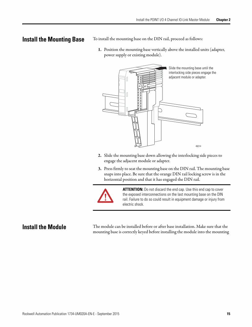
Install the Mounting Base To install the mounting base on the DIN rail, proceed as follows:
1. Position the mounting base vertically above the installed units (adapter, power supply or existing module).
2. Slide the mounting base down allowing the interlocking side pieces to engage the adjacent module or adapter.
3. Press firmly to seat the mounting base on the DIN rail. The mounting base snaps into place. Be sure that the orange DIN rail locking screw is in the horizontal position and that it has engaged the DIN rail.
Install the Module The module can be installed before or after base installation. Make sure that the mounting base is correctly keyed before installing the module into the mounting
ATTENTION: Do not discard the end cap. Use this end cap to cover the exposed interconnections on the last mounting base on the DIN rail. Failure to do so could result in equipment damage or injury from electric shock.
Slide the mounting base until the interlocking side pieces engage the adjacent module or adapter.
46014
Rockwell Automation Publication 1734-UM020A-EN-E - September 2015 15

Chapter 2 Install the POINT I/O 4 Channel IO-Link Master Module
base. In addition, make sure the mounting base locking screw is positioned horizontal referenced to the base.
1. Using a bladed screwdriver, rotate the keyswitch on the mounting base clockwise until the number required for the type of module being installed aligns with the notch in the base.
2. Make certain the DIN rail locking screw is in the horizontal position. You cannot insert the module if the locking mechanism is unlocked.
3. Insert the module straight down into the mounting base.
4. Press to secure. The module locks into place.
Turn the keyswitch to align the number with the notch. Notch position 2 is shown.
Be sure the DIN-rail locking screw is in the horizontal position.
1734-TB Base
44229
Turn the keyswitch to align the number with the notch. Notch position 2 is shown.
Be sure the DIN-rail locking screw is in the horizontal position.
1734-TOP Base
44228
24VDC
Source
Output
Module
Status
Network
Status
1734OB4E
NODE:
0
1
2
3
24V DC
SIO
IO LINK
Module
Status
Network
Status
1734-4IOL
0
0
1
1
2
2
3
3
NODE:
44013
16 Rockwell Automation Publication 1734-UM020A-EN-E - September 2015

Install the POINT I/O 4 Channel IO-Link Master Module Chapter 2
Install the Removable Terminal Block
A removable terminal block (RTB) is supplied with your wiring base assembly. To remove, pull up on the RTB handle. This allows the mounting base to be removed and replaced as necessary without removing any of the wiring. To reinsert the removable terminal block, proceed as follows:
1. Insert the end opposite the handle into the base unit. This end has a curved section that engages with the wiring base.
2. Rotate the terminal block into the wiring base until it locks itself in place.
3. If an I/O module is installed, snap the RTB handle into place on the module.
Remove a Mounting Base To remove a mounting base, you must remove any installed module and the module installed in the base to the right. Remove the removable terminal block, if wired.
1. Unlatch the RTB handle on the I/O module.
2. Pull on the RTB handle to remove the removable terminal block.
3. Press on the module lock on the top of the module.
4. Pull on the I/O module to remove from the base.
5. Repeat steps 1, 2, 3 and 4 for the module to the right.
6. Use a small bladed screwdriver to rotate the orange base locking screw to a vertical position. This releases the locking mechanism.
7. Lift straight up to remove.
24V DC
SIO
IO LINK
Module
Status
Network
Status
1734-4IOL
0
0
1
1
2
2
3
3
NODE: Insert the module straight down into the mounting base.
Hook the RTB end into the mounting base end and rotate until it locks into place.
44012
Rockwell Automation Publication 1734-UM020A-EN-E - September 2015 17

Chapter 2 Install the POINT I/O 4 Channel IO-Link Master Module
Wire the Modules To wire the module, refer to the diagrams and tables.
POINT I/O 4-Channel IO-Link Master Module – 1734-4IOL
POINT I/O 4-Channel IO-Link Master Module Wiring – IO-Link Mode
Channel Common Voltage
0 4 6
1 5 7
2 4 6
3 5 7
Connect common on 3-wire inputs. Power is supplied through the internal power bus.
1734-4IOL
Channel 0
C
V
Channel 1
Channel 3Channel 2
C
V
Ch = IO-Link channelC = CommonV = VoltageDevice = IO-Link device (actuators, sensors)
Ch 0
C
V
C
V
Ch 1
Ch 2 Ch 3
0 1
2 3
4 5
6 7
3-wire 3-wire
DeviceDevice
18 Rockwell Automation Publication 1734-UM020A-EN-E - September 2015

Install the POINT I/O 4 Channel IO-Link Master Module Chapter 2
POINT I/O 4 Channel IO-Link Master Module Wiring – Standard Digital Input Mode
POINT I/O 4 Channel IO-Link Master Module Wiring – Standard Digital Output Mode
Channel Input Common Voltage
Channel 0 0 4 6
Channel 1 1 5 7
Channel 2 2 4 6
Channel 3 3 5 7
Connect common on 3-wire inputs. Power is supplied through the internal power bus.
Channel Output Common Voltage
Channel 0 0 4 6
Channel 1 1 5 7
Channel 2 2 4 6
Channel 3 3 5 7
Connect voltage on 3-wire outputs. Power is supplied through the internal power bus.
In = Input channelC = CommonV = Voltage
2-wire 3-wire 3-wire 2-wireIn 0
C
V
C
V
In 1
In 2 In 3
0 1
2 3
4 5
6 7
Out = Output channelC = CommonV = Voltage
2-wire3-wire 3-wire2-wireOut 0
C
V
C
V
Out 1
Out 2 Out 3
0 1
2 3
4 5
6 7
Rockwell Automation Publication 1734-UM020A-EN-E - September 2015 19

Chapter 2 Install the POINT I/O 4 Channel IO-Link Master Module
Notes:
20 Rockwell Automation Publication 1734-UM020A-EN-E - September 2015

Chapter 3
Add the POINT I/O 4 Channel IO-Link Master Module on an EtherNet/IP Network
About This Chapter In this chapter, you will learn how to perform the following tasks:• Install the POINT I/O 4 Channel IO-Link Master module Add-on
Profile• Add a POINT I/O 4 Channel IO-Link Master module in Studio 5000
when using EtherNet/IP adapters• Understand how object tags are created for your use
Install the POINT I/O 4 Channel IO-Link Master Add-On Profile
Before you can use your POINT I/O 4 Channel IO-Link Master Module in Studio 5000, you must set up the module profile so that it can be recognized.
Follow these steps to set up the profile.
1. In the installation package, double-click MPSetup.exe. The Welcome dialog box appears. Click Next.
IMPORTANT The illustrations of the Studio 5000 Module Profile Setup software dialog boxes shown in this manual are samples. Because your system configurations or the firmware kits are different, the dialog boxes you see when running the tool may be different from the ones you see here.
Rockwell Automation Publication 1734-UM020A-EN-E - September 2015 21

Chapter 3 Add the POINT I/O 4 Channel IO-Link Master Module on an EtherNet/IP Network
2. Read and agree to the license and click Next.
3. Select the option to install Studio 5000 Module Profile and click Next.
22 Rockwell Automation Publication 1734-UM020A-EN-E - September 2015
Add the POINT I/O 4 Channel IO-Link Master Module on an EtherNet/IP Network Chapter 3
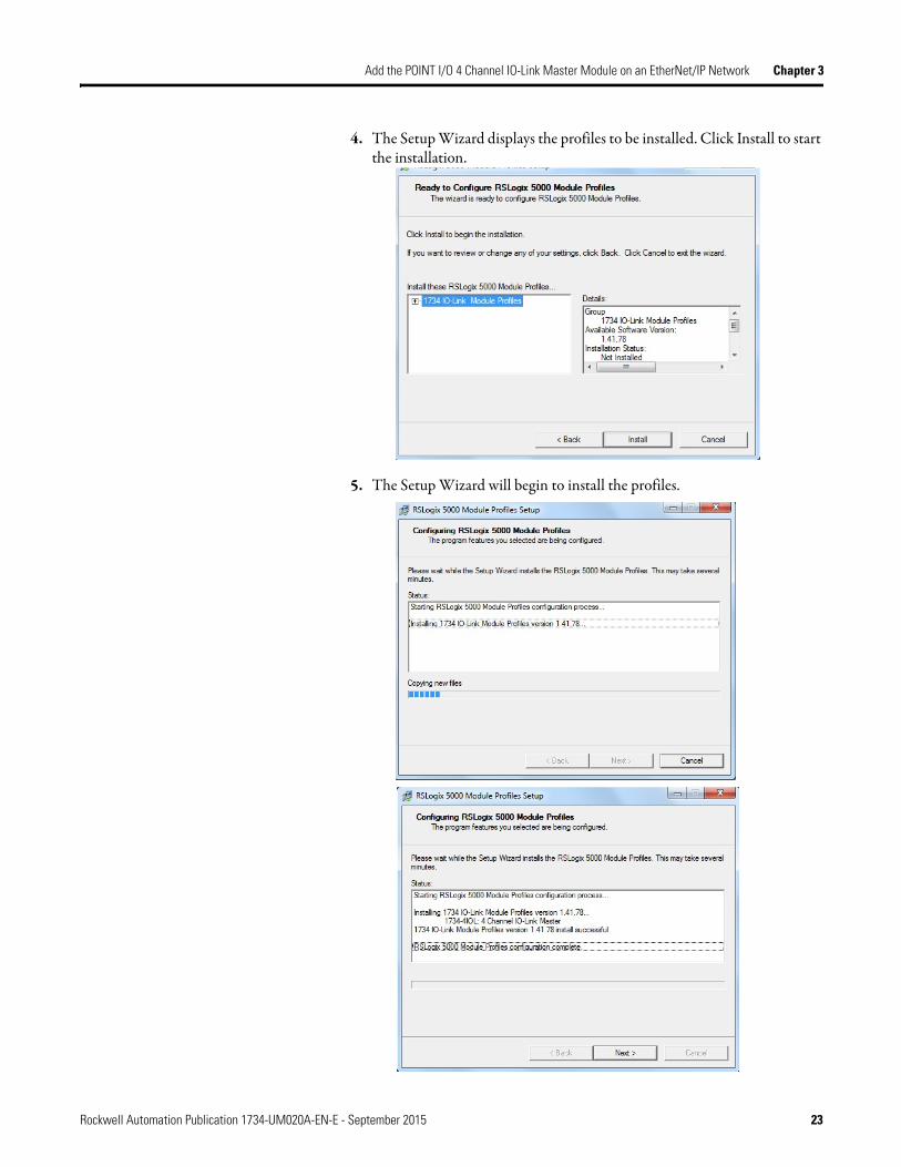
4. The Setup Wizard displays the profiles to be installed. Click Install to start the installation.
5. The Setup Wizard will begin to install the profiles.
Rockwell Automation Publication 1734-UM020A-EN-E - September 2015 23
Chapter 3 Add the POINT I/O 4 Channel IO-Link Master Module on an EtherNet/IP Network
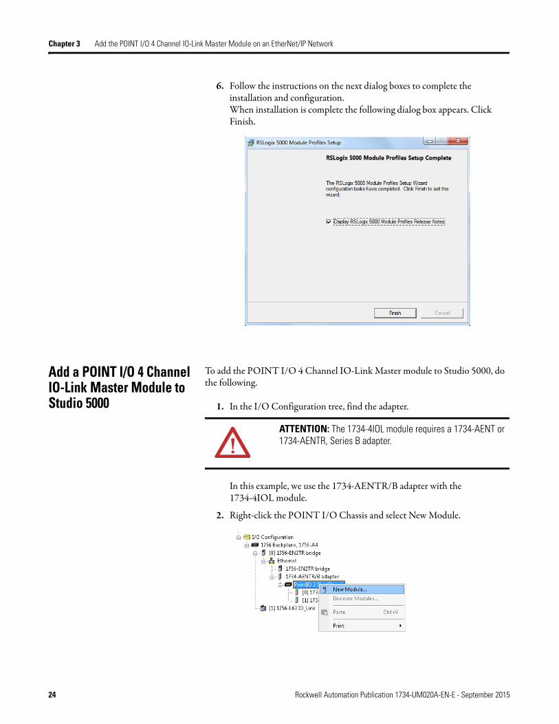
6. Follow the instructions on the next dialog boxes to complete the installation and configuration.When installation is complete the following dialog box appears. Click Finish.
Add a POINT I/O 4 Channel IO-Link Master Module to Studio 5000
To add the POINT I/O 4 Channel IO-Link Master module to Studio 5000, do the following.
1. In the I/O Configuration tree, find the adapter.
In this example, we use the 1734-AENTR/B adapter with the 1734-4IOL module.
2. Right-click the POINT I/O Chassis and select New Module.
ATTENTION: The 1734-4IOL module requires a 1734-AENT or 1734-AENTR, Series B adapter.
24 Rockwell Automation Publication 1734-UM020A-EN-E - September 2015

Add the POINT I/O 4 Channel IO-Link Master Module on an EtherNet/IP Network Chapter 3
3. Under the Specialty, Digital, or Communications category, double-click the 1734-4IOL module.
The General tab of the Add-on Profile appears.
4. Select the slot number from the Slot drop-down menu.
On the General tab, you can give the module a Name which is also used in the name of the Tag elements that get created for the module, change the Electronic Keying for the module, and configure the module channel modes using the Change button under Module Definition.
Rockwell Automation Publication 1734-UM020A-EN-E - September 2015 25

Chapter 3 Add the POINT I/O 4 Channel IO-Link Master Module on an EtherNet/IP Network
On the Connection tab, you can change the Requested Packet Interval (RPI) (the default is 20 ms.), choose to inhibit the module, configure the controller so that a loss of connection to this module causes a major fault, and view module faults. For the IO-Link Master module, the lowest allowable RPI is 2ms.
The Module Info tab will display the status and identity information of the IO-Link Master module when the module is online.
26 Rockwell Automation Publication 1734-UM020A-EN-E - September 2015

Add the POINT I/O 4 Channel IO-Link Master Module on an EtherNet/IP Network Chapter 3
On the Fault/Program tab, you can configure the state of the outputs during Program and Fault modes for channels that are configured as standard digital output or IO-Link.
On the Configuration tab, you can change the Input Filter Time for each channel configured as standard digital input.
Rockwell Automation Publication 1734-UM020A-EN-E - September 2015 27

Chapter 3 Add the POINT I/O 4 Channel IO-Link Master Module on an EtherNet/IP Network
On the IO-Link tab, you can add and delete IO-Link devices to the channels of the Master Module configured as IO-Link, modify information for IO-Link channels, register IO-Link Device Description (IODD) files, and configure parameters for IO-Link devices.
IO-Link Tag Elements
Logix tag elements get created by the Add-on Profile based on the level of integration for each IO-Link device. There are three levels currently offered:
• Generic integration is available for all IO-Link devices and does not require an IODD file.
• IODD Basic integration is available for all IO-Link devices and requires that an IODD file be registered with Studio 5000 software.
• IODD Advanced integration is available for Rockwell Automation and partner IO-Link devices, and is heavily dependent on a well-formed IODD file being registered with Studio 5000 software.
The Generic level of integration allows any IO-Link device to communicate with the Logix controller. SINT arrays are created for the device's Process Data. The size of the arrays default to 32 bytes in/out but can be modified. Device level keying is supported but there is no device parameter management provided. This must be done using message instructions to read/write data from the device. Further, data type conversion and endian swapping may be required in ladder logic.
The IODD Basic level of integration is similar to the Generic integration described above except that the size of the SINT arrays created for the device's Process Data is taken from the device's IODD file.
For the IODD Advanced level of integration, Logix tag elements are determined by the Process Data available for each IO-Link device, with detailed tag member
28 Rockwell Automation Publication 1734-UM020A-EN-E - September 2015

Add the POINT I/O 4 Channel IO-Link Master Module on an EtherNet/IP Network Chapter 3
names being created based on information from the IODD file. The Master Module translates and maps the information from IO-Link data types to Logix data types and also performs big-endian to little-endian (and little-endian to big-endian) swapping as required. Additionally, the device's configuration parameters are stored by the controller and automatically provided to the device and/or IO-Link Master on power loss and/or replacement.
I/O Tags
For channels that are configured for either standard digital input or standard digital output, standard Logix tag elements are created in line with the other POINT I/O catalogs.
Configuration Data
A Configuration tag is created for each Master Module. The Configuration Data Type includes the following:
• Fault/Program mode setting – For channels configured as standard digital output and IO-Link.Valid values for channels configured as standard digital output are as follows:− Off – value set to 100 (default)− On – value set to 101− Hold – value set to 102
Valid values for channels configured as IO-Link are as follows:− All Zeros – value set to 103 (default)− Hold – value set to 104− Device Decides – value set to 105. The IO-Link Master module gives
the control to the IO-Link device, and the IO-Link device would follow what the device vendor had specified as a fault or program state for that device.
For channels configured as disabled or standard digital input, the fault or program mode is -1 (default).
• Digital filter settings – For channels configured as standard digital input. The valid range is from zero to 65 milliseconds with the default setting of zero.
Details on configuring the module can be found in Chapter 4 and Chapter 5.
Rockwell Automation Publication 1734-UM020A-EN-E - September 2015 29

Chapter 3 Add the POINT I/O 4 Channel IO-Link Master Module on an EtherNet/IP Network
Notes:
30 Rockwell Automation Publication 1734-UM020A-EN-E - September 2015

Chapter 4
Configure the POINT I/O 4 Channel IO-Link Master as IO-Link Master Using the Studio 5000 Add-on Profile
About This Chapter In this chapter, you will learn how to configure the module as an IO-Link Master using the Studio 5000 Add-on Profile.
This chapter covers the following topics:• Typical IO-Link user interface roles, and what is accessible from the
Add-on Profile• Different IO-Link device integration levels• Configuration of the POINT I/O 4 Channel IO-Link Master module as
IO-Link Master in the Studio 5000 Add-on Profile• Configuration of IO-Link device parameters from the Add-on Profile and
by message instructions
User Roles IO-Link user interfaces are typically divided into three separate role types, which are Observation, Maintenance, and Specialist roles. The device vendor decides how to organize and allow access for the roles in view in the interface.
• Observation Role - This menu type role is designed for users who may not carry out any modification on the device and are often more restricted by read-only access. This assures that while visibility is allowed, critical parameters are not changed.
• Maintenance Role - This menu type role is designed for users who undertake functional editing, but are allowed limited access to more critical parameter types.
• Specialist Role - This menu type role is designed for users to have total access to the device and all associated parameter types. For example, all read-write parameters could be viewed and changed.
The POINT I/O 4 Channel IO-Link Master Module assumes the visibility of the Specialist Role in the IODD file. Anything that is available in Specialist Role view is available in the Add-on Profile. The Observation Role and Maintenance views are not supported in the Add-on Profile.
Rockwell Automation Publication 1734-UM020A-EN-E - September 2015 31
Chapter 4 Configure the POINT I/O 4 Channel IO-Link Master as IO-Link Master Using the Studio 5000 Add-on Profile
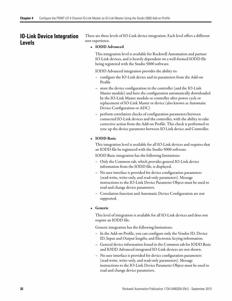
IO-Link Device Integration Levels
There are three levels of IO-Link device integration. Each level offers a different user experience.
• IODD Advanced
This integration level is available for Rockwell Automation and partner IO-Link devices, and is heavily dependent on a well-formed IODD file being registered with the Studio 5000 software.
IODD Advanced integration provides the ability to:– configure the IO-Link device and its parameters from the Add-on
Profile– store the device configuration in the controller (and the IO-Link
Master module) and have the configuration automatically downloaded by the IO-Link Master module or controller after power cycle or replacement of IO-Link Master or device (also known as Automatic Device Configuration or ADC)
– perform correlation checks of configuration parameters between connected IO-Link devices and the controller, with the ability to take corrective action from the Add-on Profile. This check is performed to sync up the device parameter between IO Link device and Controller.
• IODD BasicThis integration level is available for all IO-Link devices and requires that an IODD file be registered with the Studio 5000 software. IODD Basic integration has the following limitations:– Only the Common tab, which provides general IO-Link device
information from the IODD file, is displayed.– No user interface is provided for device configuration parameters
(read-write, write-only, and read-only parameters). Message instructions to the IO-Link Device Parameter Object must be used to read and change device parameters.
– Correlation function and Automatic Device Configuration are not supported.
• Generic
This level of integration is available for all IO-Link devices and does not require an IODD file.
Generic integration has the following limitations:– In the Add-on Profile, you can configure only the Vendor ID, Device
ID, Input and Output lengths, and Electronic keying information.– General device information found in the Common tab for IODD Basic
and IODD Advanced integrated IO-Link devices are not shown.– No user interface is provided for device configuration parameters
(read-write, write-only, and read-only parameters). Message instructions to the IO-Link Device Parameter Object must be used to read and change device parameters.
32 Rockwell Automation Publication 1734-UM020A-EN-E - September 2015
Configure the POINT I/O 4 Channel IO-Link Master as IO-Link Master Using the Studio 5000 Add-on Profile Chapter 4
– Correlation function and Automatic Device Configuration are not supported.
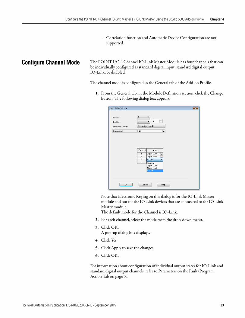
Configure Channel Mode The POINT I/O 4 Channel IO-Link Master Module has four channels that can be individually configured as standard digital input, standard digital output, IO-Link, or disabled.
The channel mode is configured in the General tab of the Add-on Profile.
1. From the General tab, in the Module Definition section, click the Change button. The following dialog box appears.
Note that Electronic Keying on this dialog is for the IO-Link Master module and not for the IO-Link devices that are connected to the IO-Link Master module.The default mode for the Channel is IO-Link.
2. For each channel, select the mode from the drop-down menu.
3. Click OK. A pop-up dialog box displays.
4. Click Yes.
5. Click Apply to save the changes.
6. Click OK.
For information about configuration of individual output states for IO-Link and standard digital output channels, refer to Parameters on the Fault/Program Action Tab on page 51
Rockwell Automation Publication 1734-UM020A-EN-E - September 2015 33

Chapter 4 Configure the POINT I/O 4 Channel IO-Link Master as IO-Link Master Using the Studio 5000 Add-on Profile
Configure IO-Link Devices IO-Link devices are configured in the IO-Link tab of the Add-on Profile.
The IO-Link tab consists of a Channel tree on the left and a working pane on the right.
The Channel tree shows the Master Module (the 1734-4IOL module) at the top, followed by the channels below it. Channels show their mode configuration (standard digital input, standard digital output, IO-Link, or Disabled) as assigned in the General tab. For channels configured as IO-Link, you can:
• Register IO-Link Device Description (IODD) files• Add, change, or delete an IO-Link device
The working pane on the right shows information about the selected channel or device from the Channel tree. From this pane, you can:
• Change channel configuration• Add, change, or delete an IO-Link device• Configure IO-Link device parameters
• Refresh IO-Link device parameters
Register an IODD file An IO-Link Device Description (IODD) file is a set of multiple files including a file in XML format, which describes all parameters associated with the device. The IODD set also includes graphic image files of the device and vendor logo.
Before you proceed with this task, take note that:• Only IODD files based on IO-Link specification v1.0.1 or v1.1 can be
registered.
34 Rockwell Automation Publication 1734-UM020A-EN-E - September 2015

Configure the POINT I/O 4 Channel IO-Link Master as IO-Link Master Using the Studio 5000 Add-on Profile Chapter 4
• You need administrator rights for the machine where the Add-on Profile is installed to be able to register an IODD file.
To register an IODD file:
1. From the IO-Link tab, in the Channel tree, right-click on the IO-Link channel.
2. Select Register IODD.The following dialog box appears.
Rockwell Automation Publication 1734-UM020A-EN-E - September 2015 35

Chapter 4 Configure the POINT I/O 4 Channel IO-Link Master as IO-Link Master Using the Studio 5000 Add-on Profile
3. Click Register IODD. The following dialog box appears.
4. Locate the IODD XML file, and then click Open. This returns you to the previous dialog box that shows the tree list view of registered IODD files.
5. Click Exit.
Add an IO-Link Device After you register an IODD file, you can add an IO-Link device to an IO-Link channel. This configuration can only be done while the project is offline.
1. In the channel tree, right-click on the IO-Link channel, and then select Change.Alternatively, you can click the Change button on the working pane.The following dialog box appears.
36 Rockwell Automation Publication 1734-UM020A-EN-E - September 2015

Configure the POINT I/O 4 Channel IO-Link Master as IO-Link Master Using the Studio 5000 Add-on Profile Chapter 4
2. Click the button in the Change Device column for the IO-Link channel.The following dialog box appears.
3. Select the IO-Link device from the tree.
4. Click Create.
5. Click the OK button from the Change Channel Configuration dialog box.A pop-up dialog box displays.
6. Click Yes. You will be reverted to the General tab.
7. Click Apply to save the changes, and then click OK.
Note that you can also add a Generic IO-Link device that does not have an IODD file. Refer to Configure IO-Link Device Parameters Using Message Instructions on page 46 for more information.
Change IO-Link Channel Configuration
You can change the Application Specific Name, Electronic Keying, and Process Data Input configuration for an IO-Link channel while the project is in Offline mode.
Before you proceed with this task, take note that:
Rockwell Automation Publication 1734-UM020A-EN-E - September 2015 37

Chapter 4 Configure the POINT I/O 4 Channel IO-Link Master as IO-Link Master Using the Studio 5000 Add-on Profile
• The Application Specific Name cannot be changed for a Generic IO-Link device.
• For a Generic IO-Link device, the Vendor ID and Device ID cannot be 0 when Electronic Keying is set to Exact Match.
To change IO-Link Channel configuration:
1. In the IO-Link tab, click Change. The following dialog box appears.
2. Modify the information.a. Application Specific Name - Enter an application-specific name.
The purpose of the Application Specific Name is to add themed naming to distinguish the sensors within the machine and the associated project profile in the Add-on Profile. This allows for easier maintenance and operation since the device is further identified by how it is used on the machine/project. The application specific name can also be changed from the IO-Link device’s Identification tab if the tab is available.
b. Electronic Keying Information - Select Exact Match or Disabled from the drop-down menu.The Exact Match and Disabled keying options in this dialog correspond to the Compatible and No Check keying options in IO-Link terminology respectively. When Exact Match is selected, the connected IO-Link device must have the same Vendor ID and Device ID information that has been configured for that channel. If they do not match, IO-Link communications will not be established and a Keying Fault status bit will be set.When Disabled is selected, key check is not performed.
c. Process Data Input - Select the input data from the drop-down menu (for devices that support multiple layouts of input data).
3. Click OK. A pop-up dialog box displays.
4. Click Yes. You will be reverted to the General tab.
5. Click Apply to save the changes.
6. Click OK.
38 Rockwell Automation Publication 1734-UM020A-EN-E - September 2015

Configure the POINT I/O 4 Channel IO-Link Master as IO-Link Master Using the Studio 5000 Add-on Profile Chapter 4
Configure IO-Link Device Parameters Using the Add-on Profile
After you add an IO-Link device, you can configure device parameters for IO-link devices with IODD Advanced integration level from the Add-on Profile.
Before you proceed with this task, take note that:• Parameters vary depending on data provided in the IODD file of an
IO-Link device.• You cannot change or read a Generic IO-Link device’s parameters from the
Add-on Profile. Refer to Configure IO-Link Device Parameters Using Message Instructions on page 46 for more information.
1. In the Channel tree, click the IO-Link device under the IO-Link channel.The Common tab appears on the working pane. Depending on the data provided in the IODD file, up to four more tabs may be shown for the selected device: Identification, Observation, Parameter, and Diagnosis.
The Common tab provides general device information taken from the IODD file including the vendor logo and an image of the device.
Rockwell Automation Publication 1734-UM020A-EN-E - September 2015 39

Chapter 4 Configure the POINT I/O 4 Channel IO-Link Master as IO-Link Master Using the Studio 5000 Add-on Profile
The Identification tab contains parameters with device identity information such as revisions and serial number. The application specific name of the device can also be changed from this tab.
The Observation tab contains only I/O data, which can be used for debugging.
40 Rockwell Automation Publication 1734-UM020A-EN-E - September 2015

Configure the POINT I/O 4 Channel IO-Link Master as IO-Link Master Using the Studio 5000 Add-on Profile Chapter 4
The Parameter tab holds the most commonly used parameters to set up an IO-Link device. Parameters with the highest usage are placed at the top.
The Diagnosis tab contains parameters for trouble-shooting the IO-Link device such as temperature.
Rockwell Automation Publication 1734-UM020A-EN-E - September 2015 41

Chapter 4 Configure the POINT I/O 4 Channel IO-Link Master as IO-Link Master Using the Studio 5000 Add-on Profile
2. Select the tab where the parameter is located.Parameters are listed with their name, read-write attribute, value, and units (if available in the IODD file).
3. Change the value of read-write parameters (through either edit controls or drop-down lists) and trigger write-only parameters by pressing the button for the parameter.Ranges and enumerated choices are derived from the IODD file.
4. Click Apply.
IO-Link Device Parameter Behavior
IO-Link parameters are shown in the Add-on Profile only for IO-Link devices with IODD Advanced integration. Each parameter can have an attribute of read-only (ro), read-write (rw), or write-only (wo). The behavior of parameters and the source for their values differ when offline and when online.
42 Rockwell Automation Publication 1734-UM020A-EN-E - September 2015

Configure the POINT I/O 4 Channel IO-Link Master as IO-Link Master Using the Studio 5000 Add-on Profile Chapter 4
See the following table for more information.
Manage Parameter Differences Between IO-Link Devices and Controller
The Add-on Profile has a Refresh button that updates the read-only parameters for all channels with IO-Link devices. It also performs a Correlation check of the read-write parameters in all connected IO-Link devices and in the controller.
Differences in parameter values can happen when device configuration is changed externally, such as through a device console during operation. If there are differences found after running a Correlation check, you can choose, on a per channel basis, to use the parameters that are currently in the connected IO-Link device or to use the parameters that are stored in the controller.
Before you proceed with this task, take note of the following:• The Refresh button is only enabled in Online mode.• Correlation check is performed initially when the Add-on Profile is
launched in Online mode.• Correlation check is only performed on IO-Link devices with IODD
Advanced integration.
IO-Link Device Parameter Behavior
Attribute Offline Online
Read-only"ro"
Parameters are blank. Parameter values are read from the connected IO-Link device.Parameters show "??" when communication breaks.
Read-write"rw"
Parameter values are read from the IODD file when the IO-Link device is added.Changes made to the parameters are applied when the OK or Apply buttons are clicked.
Parameter values can be edited and changes made to the parameters are applied when the OK or Apply buttons are clicked.Changes are sent to the Master Module, which then writes the changes to the connected IO-Link device.
Write-only"wo"
Parameter buttons are disabled. Parameter buttons that could potentially impact the Process Data are disabled.Other parameter buttons enabled and result in commands being sent to the connected IO-Link device.
Rockwell Automation Publication 1734-UM020A-EN-E - September 2015 43

Chapter 4 Configure the POINT I/O 4 Channel IO-Link Master as IO-Link Master Using the Studio 5000 Add-on Profile
1. From the IO-Link tab, on the working pane, click the Refresh button.If differences are detected, a dialog box appears and displays mismatch information per channel, including the parameters and the values present in the device and in the controller.
2. For each channel, select the checkbox for the corrective action: • Use Project Values - downloads the parameters values from the project
to the connected IO-Link device.• Use Device Values - uploads the parameters values read from the
connected IO-Link device to the project.
3. Click OK. If you click the Cancel button without choosing a corrective action, the read-write parameters of the affected channels will display "??".
4. Click Apply to save the changes.
Add a Generic IO-Link Device
You can add a Generic IO-Link device, which does not have an IODD file, to an IO-Link channel and edit its properties using the Add-on Profile.
When adding a Generic IO-Link device, take note of the following:• Automatic Device Configuration and the Correlation function are not
supported for Generic IO-Link devices.• You cannot change or read the Generic IO-Link device’s parameter values
through the Add-on Profile. Instead, message instructions to the IO-Link Device Parameter Object must be used.
44 Rockwell Automation Publication 1734-UM020A-EN-E - September 2015

Configure the POINT I/O 4 Channel IO-Link Master as IO-Link Master Using the Studio 5000 Add-on Profile Chapter 4
1. In the channel tree, right-click on the IO-Link channel, and then select Change.Alternatively, you can click the Change button on the working pane.The following dialog box appears.
2. Click the button in the Change Device column for the IO-Link channel.The following dialog box appears.
3. Expand the tree selection, and then select Generic Device (last item on the list).
4. Click Create.The following dialog appears.
5. Edit generic IO-Link device properties.a. Electronic Keying - Select Disabled (default) or Exact Match.
The Vendor ID and Device ID cannot be 0 if the Electronic Keying is set to Exact Match.
b. Vendor ID - Enter the vendor ID of the IO-Link device. This field is disabled if Electronic Keying is Disabled.
c. Device ID - Enter the device ID of the IO-Link device.This field is disabled if Electronic Keying is Disabled
Rockwell Automation Publication 1734-UM020A-EN-E - September 2015 45

Chapter 4 Configure the POINT I/O 4 Channel IO-Link Master as IO-Link Master Using the Studio 5000 Add-on Profile
d. Input length - Enter the input length in bytes of the IO-Link device. Valid range is 0…32. The value is obtained from the device vendor.
e. Output length - Enter the output length in bytes of the IO-Link device. Valid range is 0…32. The value is obtained from the device vendor.
6. Click OK. A pop-up dialog box displays.
7. Click Yes.
8. Click Apply to save the changes.
9. Click OK.
Configure IO-Link Device Parameters Using Message Instructions
Use message instructions to the IO-Link Device Parameter Object to read or change configuration parameters for IO-Link devices with IODD Basic or Generic integration.
About the IO-Link Device Parameter Object
IO-Link device configuration parameters include multiple sets of index/subindex pairs, a length, and a data value that is sent to the Master Module through instances of the IO-Link Device Parameter Object.
The IO-Link Device Parameter Object provides a mechanism for a CIP client to access parameters within an IO-Link device. Within this class, the instance number maps to an IO-Link index value.
The details of each index and subindex depend entirely on the IO-Link device and are described in the IO-Link Data Description (IODD) XML file for that device or data sheet provided by the device vendor.
Create a Message Instruction for the IO-Link Device
Before you proceed, take note of the following: • For IODD Advanced integration, when you change IO-Link device
parameters by message instruction, a correlation check is performed when the Add-on Profile is launched. You can then select to use either the device or controller parameter values.
• Messages to/from IO-Link parameters are raw IO-Link data format. As such, unsigned, packed bits and endian/byte swapping issue need to be handled accordingly. Ladders have to be created to enable byte swapping of values from the MSG instruction.
• Refer to the Studio 5000 help for more information on how to create message instructions.
To configure IO-Link device parameters using message instructions:
1. In Studio 5000, go to Input/Output Instruction set and create a MSG instruction.
46 Rockwell Automation Publication 1734-UM020A-EN-E - September 2015

Configure the POINT I/O 4 Channel IO-Link Master as IO-Link Master Using the Studio 5000 Add-on Profile Chapter 4
2. Create a controller tag for this instance of message instruction.
3. Configure the message instruction as follows.
Message Configuration
In this tab For this item Type or choose
Communication Path the IO-Link Master module.
Configuration Message Type CIP Generic
Service Type Custom
Service Code (Hex) the applicable service code
Service Code Service Name Description
4B Read_Subindex Reads a parameter value from the IO-Link device.
4C Write_Subindex Writes a parameter value to the IO-Link device.
4D Read_Index Reads an entire index (all parameters within an index) from the IO-Link device (uses subindex 0)
4E Write_Index Writes an entire index (all parameters within an index) to the IO-Link device (uses subindex 0).
Class 3A3
Instance the device-specific parameter index value as specified by the device vendor.Refer to Locate the Parameter Index or Subindex Value in the IODD File on page 48 for more information.
Attribute 0
Source Element one of the following according to the service code.
4B (read subindex) source_array where source element data type is SINT[2]. In this case SINT[0] is subindex as provided by the Device vendor, SINT[1] is the channel number from where the data has to be read. The channel value ranges from 0 to 3. The value must be in hex.Refer to Read Subindex Request Parameters on page 48 for more information.
4C (write subindex) a local source tag that contains data that is to be sent with the service. The source element will have a byte for the subindex number, a byte for the channel number, followed by the bytes of data that need to be written.Refer to Write Subindex Request Parameters on page 48 for more information.
4D (read index) source_array where source element data type is SINT. In this case the SINT is the channel number from where the data has to be read. The channel value ranges from 0 to 3. The value must be in hex.Refer to Read Index Request Parameters on page 48 for more information.
4E (write index) a local source tag that contains data that is to be sent with the service. The source element will have a byte for the index number, a byte for the channel number, followed by the bytes of data that need to be written.Refer to Write Index Request Parameters on page 48 for more information.
Refer to Locate the Parameter Index or Subindex Value in the IODD File on page 48 for more information.
Source Length (bytes) one of the following according to the service code.
4B (read subindex) the length of the source element.
4C (write subindex) the length of the source element.
4D (read index) the length of the source element.
4E (write index) the length of the source element.
Destination Element destination_array tag that will contain data received from the service.The controller tag specified in destination element must be SINT[X] or DINT[X] data type, where X refers to number of bytes of data. This size is to be provided by the device vendor. This size is the size of parameter that is being read or written to the IO Link device.
Rockwell Automation Publication 1734-UM020A-EN-E - September 2015 47

Chapter 4 Configure the POINT I/O 4 Channel IO-Link Master as IO-Link Master Using the Studio 5000 Add-on Profile
Locate the Parameter Index or Subindex Value in the IODD File
The details of each index and subindex depend entirely on the IO-Link device and are described in the IO-Link Data Description (IODD) XML file for that device or data sheet provided by the device vendor.
Using the Distance Normalization parameter for an Allen-Bradley sensor (model 45LMS-U8LGC3) as an example, refer to the following diagram to see where a specific parameter can be found on the device’s IODD file.
Read Subindex Request Parameters
Name Data Type Description of ParameterSubindex USINT Subindex value of parameter to retrieve.Port USINT IO-Link channel for the IO-Link device which the request is
destined for. The maximum port number supported is indicated in class attribute 8, Number of ports.
Write Subindex Request Parameters
Name Data Type Description of ParameterSubindex USINT Subindex value of parameter to retrieve.Port USINT IO-Link channel for the IO-Link device which the request is
destined for. The maximum port number supported is indicated in class attribute 8, Number of ports.
Parameter value Array of octet Data value to be written to the IO-Link device parameter, in IO-Link format (i.e. big endian not translated to CIP data type)
Read Index Request Parameters
Name Data Type Description of ParameterPort USINT IO-Link channel for the IO-Link device which the request is
destined for. The maximum port number supported is indicated in class attribute 8, Number of ports.
Write Index Request Parameters
Name Data Type Description of ParameterPort USINT IO-Link channel for the IO-Link device which the request is
destined for. The maximum port number supported is indicated in class attribute 8, Number of ports.
Parameter values Array of octet Value of IO-Link parameters
48 Rockwell Automation Publication 1734-UM020A-EN-E - September 2015

Chapter 5
Configure the POINT I/O 4 Channel IO-Link Master Module as Standard Digital Input or Output Using the Studio 5000 Add-on Profile
About This Chapter In this chapter, you will learn how to do the following:• Configure the Module as Standard Digital Input Using the
ConfigurationTab• Configure the Module as Standard Digital Output Using the
Fault/Program ActionTab
Configure the Module as Standard Digital Input Using the Configuration Tab
The following diagram shows the Configuration tab of a POINT I/O 4 Channel IO-Link Master module in Studio 5000 using the Add-on Profile.
Each channel of your POINT I/O 4 Channel IO-Link Master module that is set to standard digital input mode can be configured with individual input filter times. The following table describes each parameter on the Configuration tab.
Rockwell Automation Publication 1734-UM020A-EN-E - September 2015 49

Chapter 5 Configure the POINT I/O 4 Channel IO-Link Master Module as Standard Digital Input or Output Using the Studio 5000 Add-on Profile
Configure the Module as Standard Digital Output Using the Fault/Program Action Tab
The following diagram shows the Fault/Program tab of a POINT I/O 4 Channel IO-Link Master module in Studio 5000 using the Add-on Profile.
Each channel of your POINT I/O 4 Channel IO-Link Master module that is set to standard digital output or IO-Link mode can be configured with individual output states.
The following table describes each parameter on the Fault/Program tab.
Parameters on the Configuration Tab
Parameter Description
Channel Displays channels that are used to set the channel’s configuration parameters.
Mode Displays channel mode for each channel.
Input Filter Time (ms)
Off->On This is the OFF to ON filter constant for all inputs on the module. A high signal must be present for this amount of time before the module will report an ON.The value must be entered in milliseconds (ms). The default value is 0 ms. The minimum value is 0 and the maximum is 65 ms.
On->Off This is the ON to OFF filter constant for all inputs on the module. A low signal must be present for this amount of time before the module will report an OFF.The value must be entered in milliseconds (ms). The default value is 0 ms. The minimum value is 0 and the maximum is 65 ms.
50 Rockwell Automation Publication 1734-UM020A-EN-E - September 2015

Configure the POINT I/O 4 Channel IO-Link Master Module as Standard Digital Input or Output Using the Studio 5000 Add-on Profile Chapter 5
Parameters on the Fault/Program Action Tab
Parameter Description
Channel Displays the channels that are used to set the channel’s configuration parameters
Mode Displays the mode that has been configured for each channel.
Output State During
Program Mode For each channel that has been configured as standard digital output or IO-Link, select the behavior of each output when the controller transitions to Program Mode.The available selections for each standard digital output channel are Off (default), On, or Hold.The available selections for each IO-Link channel are All Zeros, Hold, or Device Decides.
• When All Zeros is selected, any IO-Link output values for that channel will be set to zero.
• When Hold is selected, any IO-Link output values will be held at the current value.
• When Device Decides is selected, the Device Operate command will be sent to the IO-Link device. What the outputs of the IO-Link device do during Device Operate is determined by the device vendor.
If communication with the controller fails while in Program Mode, the output values will use the Fault Mode selection.
Fault Mode For each channel that has been configured as standard digital output or IO-Link, select the behavior of each output when communication with the controller fails.The available selections for each standard digital output channel are Off (default), On, or Hold.The available selections for each IO-Link channel are All Zeros, Hold, or Device Decides.
• When All Zeros is selected, any IO-Link output values for that channel will be set to zero.
• When Hold is selected, any IO-Link output values will be held at the current value.
• When Device Decides is selected, the Device Operate command will be sent to the IO-Link device. What the outputs of the IO-Link device do during Device Operate is determined by the device vendor.
Rockwell Automation Publication 1734-UM020A-EN-E - September 2015 51

Chapter 5 Configure the POINT I/O 4 Channel IO-Link Master Module as Standard Digital Input or Output Using the Studio 5000 Add-on Profile
Notes:
52 Rockwell Automation Publication 1734-UM020A-EN-E - September 2015
Appendix A
Connected Data Mapping
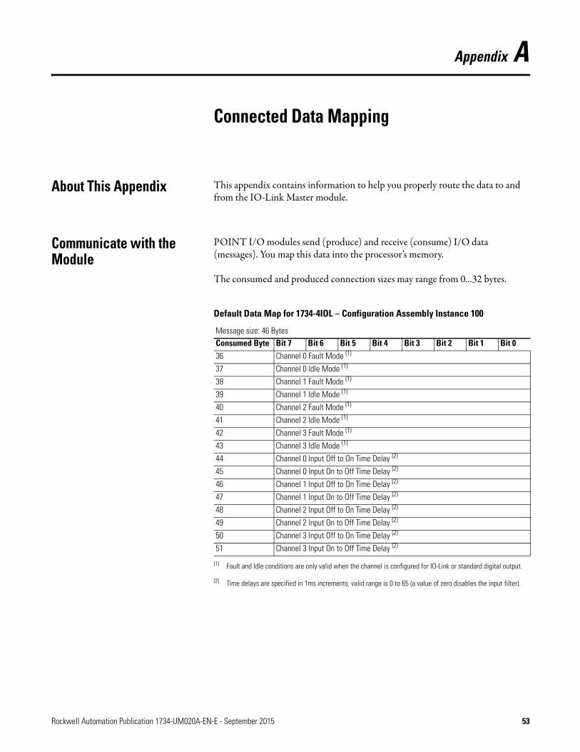
About This Appendix This appendix contains information to help you properly route the data to and from the IO-Link Master module.
Communicate with the Module
POINT I/O modules send (produce) and receive (consume) I/O data (messages). You map this data into the processor’s memory.
The consumed and produced connection sizes may range from 0...32 bytes.
Default Data Map for 1734-4IOL – Configuration Assembly Instance 100
Message size: 46 BytesConsumed Byte Bit 7 Bit 6 Bit 5 Bit 4 Bit 3 Bit 2 Bit 1 Bit 036 Channel 0 Fault Mode (1)
(1) Fault and Idle conditions are only valid when the channel is configured for IO-Link or standard digital output.
37 Channel 0 Idle Mode (1)
38 Channel 1 Fault Mode (1)
39 Channel 1 Idle Mode (1)
40 Channel 2 Fault Mode (1)
41 Channel 2 Idle Mode (1)
42 Channel 3 Fault Mode (1)
43 Channel 3 Idle Mode (1)
44 Channel 0 Input Off to On Time Delay (2)
(2) Time delays are specified in 1ms increments, valid range is 0 to 65 (a value of zero disables the input filter).
45 Channel 0 Input On to Off Time Delay (2)
46 Channel 1 Input Off to On Time Delay (2)
47 Channel 1 Input On to Off Time Delay (2)
48 Channel 2 Input Off to On Time Delay (2)
49 Channel 2 Input On to Off Time Delay (2)
50 Channel 3 Input Off to On Time Delay (2)
51 Channel 3 Input On to Off Time Delay (2)
Rockwell Automation Publication 1734-UM020A-EN-E - September 2015 53
Appendix A Connected Data Mapping
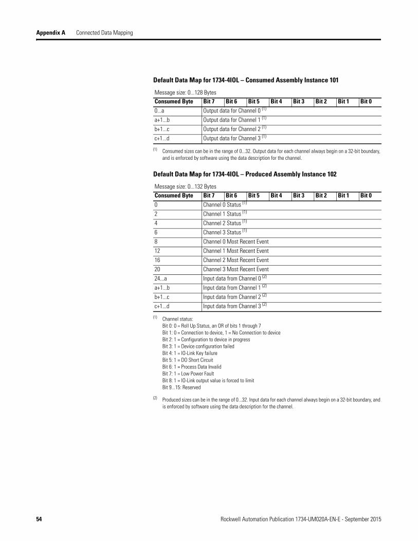
Default Data Map for 1734-4IOL – Consumed Assembly Instance 101
Message size: 0...128 BytesConsumed Byte Bit 7 Bit 6 Bit 5 Bit 4 Bit 3 Bit 2 Bit 1 Bit 00...a Output data for Channel 0 (1)
(1) Consumed sizes can be in the range of 0...32. Output data for each channel always begin on a 32-bit boundary, and is enforced by software using the data description for the channel.
a+1...b Output data for Channel 1 (1)
b+1...c Output data for Channel 2 (1)
c+1...d Output data for Channel 3 (1)
Default Data Map for 1734-4IOL – Produced Assembly Instance 102
Message size: 0...132 BytesConsumed Byte Bit 7 Bit 6 Bit 5 Bit 4 Bit 3 Bit 2 Bit 1 Bit 00 Channel 0 Status (1)
(1) Channel status:Bit 0: 0 = Roll Up Status, an OR of bits 1 through 7Bit 1: 0 = Connection to device, 1 = No Connection to deviceBit 2: 1 = Configuration to device in progressBit 3: 1 = Device configuration failedBit 4: 1 = IO-Link Key failureBit 5: 1 = DO Short CircuitBit 6: 1 = Process Data InvalidBit 7: 1 = Low Power FaultBit 8: 1 = IO-Link output value is forced to limitBit 9...15: Reserved
2 Channel 1 Status (1)
4 Channel 2 Status (1)
6 Channel 3 Status (1)
8 Channel 0 Most Recent Event
12 Channel 1 Most Recent Event
16 Channel 2 Most Recent Event
20 Channel 3 Most Recent Event
24...a Input data from Channel 0 (2)
(2) Produced sizes can be in the range of 0...32. Input data for each channel always begin on a 32-bit boundary, and is enforced by software using the data description for the channel.
a+1...b Input data from Channel 1 (2)
b+1...c Input data from Channel 2 (2)
c+1...d Input data from Channel 3 (2)
54 Rockwell Automation Publication 1734-UM020A-EN-E - September 2015

Appendix B
Supported Events
About This Appendix This appendix provides information about events that are defined in the IO Link master stack. This appendix also shows where the most recent events are viewable in the Controller Tags view of the Studio 5000 program.
IO-Link Master Module Events
IO-Link events can be accessed through Explicit Messaging by querying the Events attribute of an IO-Link Module object. This attribute contains a list of events logged from the IO-Link channel. The 25 most recent events can be viewed by querying that attribute. Refer to the following guide for more information.
Querying the Events from the master to view 25 most recent events
Class: 0x3A2 hexService: 0E hexInstance: refers to channel number and can be from 0 to 3Attribute: 15 decimal or 0F hex
Structure of the Returned Data
Name Data Type Description of AttributeIO-Link Events Array of Struct Events from IO-Link Device (Remote) or Master (Local)Sequence Count USINT Count value assigned to each event (refer to sequence
count section)Event Qualifier BYTE Type, mode and source of the Event (refer to event
qualifier table)Event Code UINT The identifier of an actual Event (refer to event code table)
Rockwell Automation Publication 1734-UM020A-EN-E - September 2015 55
Appendix B Supported Events
IO-Link Master Event Codes
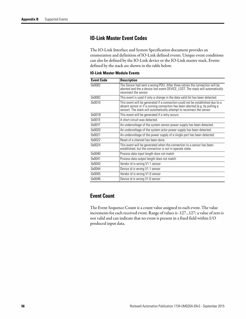
The IO-Link Interface and System Specification document provides an enumeration and definition of IO-Link defined events. Unique event conditions can also be defined by the IO-Link device or the IO-Link master stack. Events defined by the stack are shown in the table below.
Event Count
The Event Sequence Count is a count value assigned to each event. The value increments for each received event. Range of values is -127...127; a value of zero is not valid and can indicate that no event is present in a fixed field within I/O produced input data.
IO-Link Master Module Events
Event Code Description0x0002 The Sensor had sent a wrong PDU. After three retries the connection will be
aborted and the a device lost event DEVICE_LOST. The stack will automatically reconnect the sensor.
0x000C This event is used if only a change in the data valid bit has been detected.0x0010 This event will be generated if a connection could not be established due to a
absent sensor or if a running connection has been aborted (e.g. by pulling a sensor). The stack will automatically attempt to reconnect the sensor.
0x001B This event will be generated if a retry occurs.0x001E A short circuit was detected.0x001F An undervoltage of the system sensor power supply has been detected.0x0020 An undervoltage of the system actor power supply has been detected.0x0021 An undervoltage of the power supply of a single port has been detected.0x0022 Reset of a channel has been done.0x0024 This event will be generated when the connection to a sensor has been
established, but the connection is not in operate state.0x0040 Process data input length does not match0x0041 Process data output length does not match0x0043 Vendor id is wrong V1.1 sensor0x0044 Device id is wrong V1.1 sensor0x0045 Vendor id is wrong V1.0 sensor0x0046 Device id is wrong V1.0 sensor
56 Rockwell Automation Publication 1734-UM020A-EN-E - September 2015

Supported Events Appendix B
Event Qualifier
The Event Qualifier provides details about the type event, as shown in the table below.
Recent Events Controller Tag View
The following graphic shows where the most recent events are viewable in the Studio 5000 program for the 1734-4IOL IO-Link Master Module and/or any Rockwell Automation IO-Link-supported device.
Event Qualifier
Bit(s) Name Definition0 - 2 Source These bits indicate the source of an Event:
0: Unknown1: Physical Layer2: Data Layer3: Application Layer4: Application5-7: Reserved
3 Location This bit indicates the location of the Event.0: Device application (remote)1: Master application (local)
4 - 5 Type These bits indicate the Event category0: Reserved1: Notification2: Warning3: Error
6 - 7 Mode These bits indicate the Event mode0: Reserved1: Event single shot2: Event disappears3: Event appears
Rockwell Automation Publication 1734-UM020A-EN-E - September 2015 57

Appendix B Supported Events
Notes:
58 Rockwell Automation Publication 1734-UM020A-EN-E - September 2015

Appendix C
Troubleshooting
About This Appendix This appendix provides information about module diagnostics, and about troubleshooting with the following indicators:
• Module status• Network status• Standard digital I/O status (ON/OFF/fault or diagnostic)• IO-Link status
In addition, the following troubleshooting scenarios are provided:• Second Data I/O connection rejected• Controller goes to fault when enabling/disabling Unicast• Generic device with zero length input and output is accepted by the
Add-on Profile• The ChxMostRecentEvent.EventSequenceCount is an unsigned value
About Module Diagnostics All status and diagnostic information is reported back over the network communication adapter. A single point of failure is detected and reported at the module and to the control system.
Node-level diagnostics:• Module Status indicator
indicates the health of the module.
• Network Status indicatorindicates the status of the communication link.
• SIO point indicatorindicates I/O (ON/OFF or fault/diagnostic) status.
• IO-Link indicator indicates the status of each IO-Link.
Module Status
Network Status
7
1
3
0
2
ModuleStatus
NetworkStatus
24V DC
SIOIO
LINK
1734-4IOL
1
3
0
2
1
3
0
2
NODE:
NODE:
IO-Link StateStandard Digital I/O State
Rockwell Automation Publication 1734-UM020A-EN-E - September 2015 59

Appendix C Troubleshooting
Interpret LED Indicators Refer to the following diagram and table for information on how to interpret the status indicators.
POINT I/O 4-Channel IO-Link Master Module – 1734-4IOL
Indicator Status for Modules
Status DescriptionModule status Off No power applied to device.
Green Device operating normally.Flashing green Device needs commissioning due to missing, incomplete, or
incorrect configuration.Flashing red Recoverable fault.Red Unrecoverable fault occurred. Self-test failure present
(checksum failure, or ramtest failure at cycle power). Firmware fatal error present.
Flashing red/green Device is self-testing.Network status Off Device is not online:
- Device has not completed dup_MAC-id test.- Device not powered – check module status indicator.
Flashing green Device is online but has no connections in the established state.
Green Device is online and has connections in the established state.
Flashing red One or more I/O connections are in timed-out state.Red Critical link failure – failed communication device. Device
detected error that prevents it from communicating on the network.
Flashing red/green Communication faulted device – the device has detected a network access error and is in communication faulted state. Device has received and accepted an Identity Communication Faulted Request – long protocol message.
Channel status Off Standard digital input or output is in Off state, configured in IO-Link mode, or no power applied to device.
Yellow Standard digital input or output is in On state.IO-Link status Off IO-Link is disabled, channel configured as standard digital
I/O, or no power applied to device.Flashing green Port starting-up or no IO-Link device detected.Green IO-Link active. IO-Link is enabled.
7
1
3
0
2
ModuleStatus
NetworkStatus
24V DC
SIOIO
LINK
1734-4IOL
1
3
0
2
1
3
0
2
NODE:
NODE:
Module status
Network status
Status of Standard Digital I/O 0
Status of Standard Digital I/O 1
Status of Standard Digital I/O 2
Status of Standard Digital I/O 3
Status of IO-Link 0
Status of IO-Link 1
Status of IO-Link 2
Status of IO-Link 3
60 Rockwell Automation Publication 1734-UM020A-EN-E - September 2015

Troubleshooting Appendix C
Troubleshooting Scenarios The following are scenarios you may encounter while using the modules.
Second Data I/O connection rejected
The 1734-4IOL module does not support a Listen-Only or Input-Only connection. A connection attempt from a second Logix controller will be rejected.
Controller goes to fault when enabling/disabling Unicast
If the you check the “Major Fault on Controller if Connection Faults While in Run Mode” check box and uncheck the “Use Unicast Connection over EtherNet/IP” check box while online and apply the changes, the Logix controller will fault.
The work-around is to first inhibit the connection, make the changes to the two check boxes, then un-inhibit the connection.
Generic device with zero length input and output is accepted by the Add-on Profile
The input and output length for a generic device can both be set to zero. These settings will cause the communication fault bit to be set for the channel.
Rockwell Automation Publication 1734-UM020A-EN-E - September 2015 61

Appendix C Troubleshooting
The ChxMostRecentEvent.EventSequenceCount is an unsigned value
The ChxMostRecentEvent.EventSequenceCount is a count value assigned to each event. The value increments for each received event. Range of values is 1 to 255; a value of zero is not valid and can indicate that no event is present.
Because this is an unsigned number the count values from 128 through 255 will appear as negative numbers in the Logix Designer software.
62 Rockwell Automation Publication 1734-UM020A-EN-E - September 2015


Rockwell Otomasyon Ticaret A.Ş., Kar Plaza İş Merkezi E Blok Kat:6 34752 İçerenköy, İstanbul, Tel: +90 (216) 5698400
Rockwell Automation Support
Rockwell Automation provides technical information on the Web to assist you in using its products. At http://www.rockwellautomation.com/support/, you can find technical manuals, a knowledge base of FAQs, technical and application notes, sample code and links to software service packs, and a MySupport feature that you can customize to make thebest use of these tools.
For an additional level of technical phone support for installation, configuration, and troubleshooting, we offer TechConnect support programs. For more information, contact your local distributor or Rockwell Automation representative, or visit http://www.rockwellautomation.com/support/.
Installation Assistance
If you experience a problem within the first 24 hours of installation, review the information that is contained in this manual.You can contact Customer Support for initial help in getting your product up and running.
New Product Satisfaction Return
Rockwell Automation tests all of its products to ensure that they are fully operational when shipped from the manufacturing facility. However, if your product is not functioning and needs to be returned, follow these procedures.
Documentation Feedback
Your comments will help us serve your documentation needs better. If you have any suggestions on how to improve this document, complete this form, publication RA-DU002, available at http://www.rockwellautomation.com/literature/.
United States or Canada 1.440.646.3434
Outside United States or Canada
Use the Worldwide Locator at http://www.rockwellautomation.com/support/americas/phone_en.html, or contact your local Rockwell Automation representative.
United States Contact your distributor. You must provide a Customer Support case number (call the phone number above to obtain one) to your distributor to complete the return process.
Outside United States Please contact your local Rockwell Automation representative for the return procedure.
Publication 1734-UM020A-EN-E - September 2015 64Copyright © 2015 Rockwell Automation, Inc. All rights reserved.