16p-updated high power10 - dudley lab rf times microwave - hpower.pdf · high power coaxial cable,...
TRANSCRIPT

● Semi-Conductor Manufacturing Equipment● Flat Panel Manufacturing Equipment● Solar Panel Manufacturing Equipment● High Power Lasers● High Power Radars● TV/FM Broadcast● Magnetic Resonance Imaging● Other High Power RF Applications

High Power Coaxial Cable,Connectors & Assemblies
Connector Selection
Times offers a broad range of cables, connectors and assemblies for high power RF transmission. Applications such as magnetic resonance imaging (MRI), semi-conductor manufacturing equipment, flat panel manufacturing equipment, broadcast and high power lasers and radar each have their own electrical and mechanical requirements. With our broad range of solutions and capability of producing custom cables and connectors, Times is uniquely positioned to help with all of your high power RF transmission applications.
Although Times Microwave Systems is known for providing precision cable assemblies for microwave applications up to 40 GHz, we are also the leading provider of cables and assemblies for high power, low frequency applications. Our broad range of manufacturing capabilities enables us to offer rugged, flexible cables and cable assemblies, that can operate in high ambient temperatures and provide environmental resistance, while handling both high average and peak powers. Constructions are available to meet requirements for low loss, high RF shielding, and low VSWR.
Since each application requires a different set of performance characteristics, having a wide range of cables to choose from allows the trade-offs to be considered and the best cable for the application to be chosen. We produce cables with dielectrics of solid PE and PTFE, foam PE and expanded PTFE; outer conductors of round wire, flat wire and composite construtions; and jackets of PE, FEP, PVC, Urethane, Nomex®, Kapton® and other materials.
At the relatively low frequencies and high powers typically encountered in these applications, considerations for the best interface selection are very different than in microwave applications. Impedance uniformity through the interface is not as critical, but high contact forces, low contact resistance and a large interface diameter are very important. From a performance point of view, EIA flange connectors are the ideal choice with their bolt-together outer contacts and inside spring finger center-contacts. Their disadvantages include large size, high cost and time-consuming installation. Other good choices include LC’s and 7/16 DIN’s. Frequently, the equipment being connected to dictates the interface. Some interfaces that Times Microwave Systems provide include:
• C • SC• N • QDS• HN • LC• 7-16 DIN • 7/8” EIA• 1-5/8” EIA • 3-1/8”EIA• Proprietary LC quick disconnect interface
Cable Assemblies
Our capability to manufacture cables and connectors and our expertise in assembling and testing them enable us to design custom cable assemblies for your application. Built to exacting standards, we design our cable assemblies for reliability in the most extreme operating conditons. Assemblies can be matched in phase length or supplied in specific electrical lengths with customer required markings added. Complete test data on VSWR, insertion loss, corona and other parameters can be provided as required.
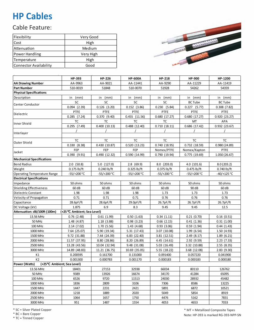
HP CablesCable Feature:
* SC = Silver Plated Copper* BC = Bare Copper* TC = Tinned Copper
* MT = Metallized Composite TapesNote: HP-393 is marked RG-393-NPP-SN
Flexibility Very GoodCost HighAttenuation MediumPower Handling Very HighTemperature HighConnector Availability Good
HP-393 HP-226 HP-600A HP-218 HP-900 HP-1200AA Drawing Number AA-9963 AA-9021 AA-11441 AA-9290 AA-11229 AA-11419Part Number 510-0019 51848 510-0070 51928 54262 54359
Description in (mm) in (mm) in (mm) in (mm) in (mm) in (mm)SC SC SC SC BC Tube BC Tube
0.094 (2.39) 0.126 (3.20) 0.152 (3.86) 0.230 (5.84) 0.227 (5.77) 0.308 (7.82)PTFE PTFE PTFE PTFE PTFE PTFE
0.285 (7.24) 0.370 (9.40) 0.455 (11.56) 0.680 (17.27) 0.680 (17.27) 0.920 (23.27)TC TC TC TC MT APA
0.295 (7.49) 0.400 (10.13) 0.488 (12.40) 0.710 (18.11) 0.686 (17.42) 0.932 (23.67)/ / / / / /
TC TC TC TC TC TC0.330 (8.38) 0.430 (10.87) 0.520 (13.23) 0.740 (18.95) 0.732 (18.59) 0.980 (24.89)
FEP FEP FEP Nomex/PTFE Nomex/Kapton PTFE0.390 (9.91) 0.490 (12.32) 0.590 (14.99) 0.790 (19.94) 0.775 (19.69) 1.050 (26.67)
Bend Radius 2.0 (50.8) 5.0 (127.0) 2.8 (69.9) 8.0 (203.0) 4.0 (101.6) 8.0 (203.2)Weight 0.175 lb/ft 0.240 lb/ft 0.325 lb/ft 0.375 lb/ft 0.475 lb/ft 0.740 lb/ftOperating Temperature Range -55/+200℃ -55/+200℃ -55/+200℃ -55/+200℃ -55/+200℃ -40/+125℃
Impedance 50 ohms 50 ohms 50 ohms 50 ohms 50 ohms 50 ohmsShielding Effectiveness 60 dB 60 dB 60 dB 60 dB 90 dB 60 dBDielectric Constant 1.98 1.98 1.98 1.73 1.73 1.73Velocity of Propagation 0.71 0.71 0.71 0.76 0.76 0.76Capacitance 28.6pF/ft 28.6pF/ft 29.0pF/ft 26.7pF/ft 26.7pF/ft 26.7pF/ftDC Voltage (kV) 1.875 6.9 8.3 9.45 9.45 12.5
13.56 MHz 0.76 (2.48) 0.61 (1.99) 0.50 (1.63) 0.34 (1.11) 0.21 (0.70) 0.16 (0.51)50 MHz 1.48 (4.87) 1.18 (3.88) 0.98 (3.23) 0.66 (2.15) 0.41 (1.36) 0.31 (1.00)100 MHz 2.14 (7.02) 1.70 (5.56) 1.43 (4.68) 0.93 (3.06) 0.59 (1.94) 0.44 (1.43)
1000 MHz 7.64 (25.07) 5.90 (19.34) 5.31 (17.43) 3.07 (10.08) 1.99 (6.54) 1.50 (4.93)1500 MHz 9.72 (31.88) 7.44 (24.39) 6.83 (22.40) 3.81 (12.51) 2.49 (8.17) 1.89 (6.21)2000 MHz 11.57 (37.95) 8.80 (28.86) 8.20 (26.89) 4.45 (14.61) 2.92 (9.59) 2.23 (7.33)2500 MHz 13.28 (43.56) 10.04 (32.94) 9.48 (31.08) 5.03 (16.49) 3.32 (10.88) 2.55 (8.35)3000 MHz 14.89 (48.83) 11.21 (36.75) 10.69 (35.05) 5.55 (18.22) 3.68 (12.08) 2.83 (9.30)
K1 0.200595 0.161700 0.131000 0.091400 0.057220 0.041900K2 0.001300 0.000783 0.001170 0.000183 0.000183 0.000180
13.56 MHz 18401 27153 32938 66034 80110 12676250 MHz 9389 13926 16674 34170 41284 65095100 MHz 6526 9720 11513 24030 28932 45482
1000 MHz 1836 2809 3106 7306 8586 132251500 MHz 1447 2231 2421 5891 6872 105212000 MHz 1218 1889 2020 5049 5854 89192500 MHz 1064 1657 1750 4476 5162 78313000 MHz 951 1487 1554 4053 4653 7033
Physical Specifications
Electrical Specifications
Mechanical Specifications
Attenuation: dB/100ft (100m) (+25℃ Ambient; Sea Level)
Power (Watts) (+25℃ Ambient; Sea Level)
Center Conductor
Dielectric
Inner Shield
Interlayer
Outer Shield
Jacket
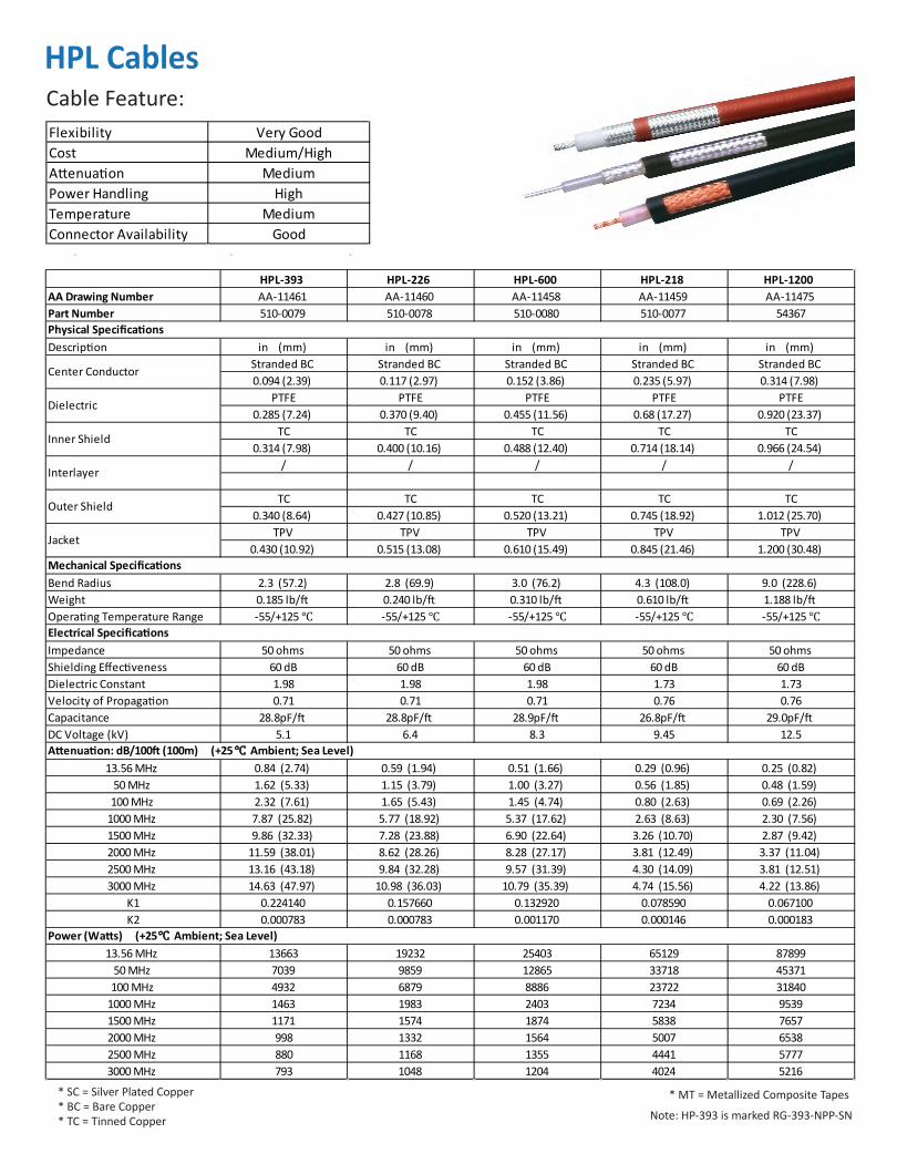
HPL CablesCable Feature:
* SC = Silver Plated Copper* BC = Bare Copper* TC = Tinned Copper
* MT = Metallized Composite Tapes
Note: HP-393 is marked RG-393-NPP-SN
Flexibility Very GoodCost Medium/HighAttenuation MediumPower Handling HighTemperature MediumConnector Availability Good
HPL-393 HPL-226 HPL-600 HPL-218 HPL-1200AA Drawing Number AA-11461 AA-11460 AA-11458 AA-11459 AA-11475Part Number 510-0079 510-0078 510-0080 510-0077 54367
Description in (mm) in (mm) in (mm) in (mm) in (mm)Stranded BC Stranded BC Stranded BC Stranded BC Stranded BC0.094 (2.39) 0.117 (2.97) 0.152 (3.86) 0.235 (5.97) 0.314 (7.98)
PTFE PTFE PTFE PTFE PTFE0.285 (7.24) 0.370 (9.40) 0.455 (11.56) 0.68 (17.27) 0.920 (23.37)
TC TC TC TC TC0.314 (7.98) 0.400 (10.16) 0.488 (12.40) 0.714 (18.14) 0.966 (24.54)
/ / / / /
TC TC TC TC TC0.340 (8.64) 0.427 (10.85) 0.520 (13.21) 0.745 (18.92) 1.012 (25.70)
TPV TPV TPV TPV TPV0.430 (10.92) 0.515 (13.08) 0.610 (15.49) 0.845 (21.46) 1.200 (30.48)
Bend Radius 2.3 (57.2) 2.8 (69.9) 3.0 (76.2) 4.3 (108.0) 9.0 (228.6)Weight 0.185 lb/ft 0.240 lb/ft 0.310 lb/ft 0.610 lb/ft 1.188 lb/ftOperating Temperature Range -55/+125℃ -55/+125℃ -55/+125℃ -55/+125℃ -55/+125℃
Impedance 50 ohms 50 ohms 50 ohms 50 ohms 50 ohmsShielding Effectiveness 60 dB 60 dB 60 dB 60 dB 60 dBDielectric Constant 1.98 1.98 1.98 1.73 1.73Velocity of Propagation 0.71 0.71 0.71 0.76 0.76Capacitance 28.8pF/ft 28.8pF/ft 28.9pF/ft 26.8pF/ft 29.0pF/ftDC Voltage (kV) 5.1 6.4 8.3 9.45 12.5
13.56 MHz 0.84 (2.74) 0.59 (1.94) 0.51 (1.66) 0.29 (0.96) 0.25 (0.82)50 MHz 1.62 (5.33) 1.15 (3.79) 1.00 (3.27) 0.56 (1.85) 0.48 (1.59)100 MHz 2.32 (7.61) 1.65 (5.43) 1.45 (4.74) 0.80 (2.63) 0.69 (2.26)
1000 MHz 7.87 (25.82) 5.77 (18.92) 5.37 (17.62) 2.63 (8.63) 2.30 (7.56)1500 MHz 9.86 (32.33) 7.28 (23.88) 6.90 (22.64) 3.26 (10.70) 2.87 (9.42)2000 MHz 11.59 (38.01) 8.62 (28.26) 8.28 (27.17) 3.81 (12.49) 3.37 (11.04)2500 MHz 13.16 (43.18) 9.84 (32.28) 9.57 (31.39) 4.30 (14.09) 3.81 (12.51)3000 MHz 14.63 (47.97) 10.98 (36.03) 10.79 (35.39) 4.74 (15.56) 4.22 (13.86)
K1 0.224140 0.157660 0.132920 0.078590 0.067100K2 0.000783 0.000783 0.001170 0.000146 0.000183
13.56 MHz 13663 19232 25403 65129 8789950 MHz 7039 9859 12865 33718 45371100 MHz 4932 6879 8886 23722 31840
1000 MHz 1463 1983 2403 7234 95391500 MHz 1171 1574 1874 5838 76572000 MHz 998 1332 1564 5007 65382500 MHz 880 1168 1355 4441 57773000 MHz 793 1048 1204 4024 5216
Physical Specifications
Mechanical Specifications
Electrical Specifications
Attenuation: dB/100ft (100m) (+25℃ Ambient; Sea Level)
Power (Watts) (+25℃ Ambient; Sea Level)
Center Conductor
Dielectric
Inner Shield
Interlayer
Outer Shield
Jacket

SFT CablesCable Feature:
Dielectric
Interlayer
Jacket
Outer Shield
Inner ShieldCenter
Conductor
Flexibility Good/Very GoodCost Very HighAttenuation LowPower Handling Very HighTemperature HighConnector Availability Good
SFT-393 SFT-226 SFT-500 SFT-600AA Drawing Number AA-8653 AA-8654 AA-11168 AA-9649Part Number 51800 51803 510-0037 51963
Description in (mm) in (mm) in (mm) in (mm)Solid SC Solid SC Stranded SC Stranded SC
0.096 (2.44) 0.131 (3.33) 0.145 (3.68) 0.160 (4.06) PTFE PTFE PTFE PTFE
0.285 (7.24) 0.370 (9.40) 0.408 (10.36) 0.455 (11.56)SC Flat Braid SC Flat Braid SC Flat Braid SC Flat Braid0.295 (7.49) 0.380 (9.65) 0.420 (10.67) 0.465 (11.81)
MT MT MT0.301 (7.65) 0.385 (9.78) 0.471 (11.96)
SC SC SC SC0.330 (8.38) 0.399 (10.14) 0.448 (11.38) 0.500 (12.70)
FEP FEP FEP FEP0.390 (9.91) 0.485 (12.32) 0.490 (12.45) 0.555 (14.10)
Bend Radius 2.0 (50.8) 2.5 (63.5) 2.5 (63.5) 2.75 (69.9)Weight 0.126 lb/ft 0.235 lb/ft 0.230 lb/ft 0.240 lb/ftOperating Temperature Range -55/+200℃ -55/+200℃ -55/+200℃ -55/+200℃
Impedance 50 ohms 50 ohms 50 ohms 50 ohmsShielding Effectiveness 100 dB 100 dB 80 dB 100 dBDielectric Constant 1.73 1.73 1.73 1.73Velocity of Propagation 0.76 0.76 0.76 0.76Capacitance 26.7pF/ft 26.7pF/ft 26.7pF/ft 26.7pF/ftDC Voltage (kV) 5 6 7 8
13.56 MHz 0.50 (1.65) 0.45 (1.49) 0.43 (1.43) 0.37 (1.21)50 MHz 0.97 (3.18) 0.87 (2.87) 0.84 (2.75) 0.71 (2.34)100 MHz 1.38 (4.52) 1.24 (4.07) 1.19 (3.91) 1.01 (3.32)
1000 MHz 4.48 (14.69) 4.04 (13.24) 3.90 (12.78) 3.30 (10.84)1500 MHz 5.53 (18.15) 4.99 (16.37) 4.82 (15.82) 4.09 (13.40)2000 MHz 6.44 (21.12) 5.81 (19.04) 5.62 (18.43) 4.76 (15.61)2500 MHz 7.25 (23.77) 6.54 (21.43) 6.33 (20.76) 5.36 (17.58)3000 MHz 7.99 (26.19) 7.20 (23.62) 6.98 (22.90) 5.91 (19.38)
K1 0.135930 0.122500 0.117433 0.099850K2 0.000180 0.000164 0.000183 0.000146
13.56 MHz 27605 37095 42102 5188850 MHz 14319 19241 21820 26900100 MHz 10090 13558 15366 18948
1000 MHz 3113 4182 4717 58261500 MHz 2522 3388 3815 47152000 MHz 2169 2915 3278 40532500 MHz 1929 2592 2912 36013000 MHz 1752 2354 2642 3268
Physical Specifications
Mechanical Specifications
Electrical Specifications
Attenuation: dB/100ft (100m) (+25℃ Ambient; Sea Level)
Power (Watts) (+25℃ Ambient; Sea Level)
NA
Center Conductor
Dielectric
Inner Shield
Interlayer
Outer Shield
Jacket

FBT CablesCable Feature:
* BCCAl = Bare Copper Clad Aluminum
Jacket
Outer Shield
Inner Shield
Dielectric
CenterConductor
Flexibility FairCost Medium/HighAttenuation LowPower Handling HighTemperature HighConnector Availability Very Good
FBT-400 FBT-500 FBT-600AA Drawing Number AA-8957 AA-8958 AA-8959Part Number 54171 54172 54173
Description in (mm) in (mm) in (mm) Solid BCCAI Solid BCCAI Solid BCCAI0.095 (2.14) 0.123 (3.12) 0.150 (3.81)
PTFE PTFE PTFE0.285 (7.24) 0.370 (9.40) 0.455 (11.56)
MT MT MT0.291 (7.39) 0.376 (9.55) 0.461 (11.71)
/ / /
TC TC TC0.320 (8.13) 0.405 (10.29) 0.490 (12.45)
FEP FEP FEP0.370 (9.40) 0.465 (11.81) 0.565 (14.35)
Bend Radius 4.0 (101.6) 5.0 (127.0) 6.0 (152.4)Weight 0.104 lb/ft 0.168 lb/ft 0.210 lb/ftOperating Temperature Range -55/+150℃ -55/+150℃ -55/+150℃Electrical SpecificationsImpedance 50 ohms 50 ohms 50 ohmsShielding Effectiveness 90 dB 90 dB 90 dBDielectric Constant 1.73 1.73 1.73Velocity of Propagation 0.76 0.76 0.76Capacitance 26.7pF/ft 26.7pF/ft 26.7pF/ftDC Voltage (kV) 5 7 8
13.56 MHz 0.48 (1.57) 0.37 (1.22) 0.30 (0.99)50 MHz 0.92 (3.02) 0.72 (2.35) 0.58 (1.91)100 MHz 1.31 (4.28) 1.02 (3.34) 0.83 (2.72)
1000 MHz 4.23 (13.87) 3.32 (10.88) 2.72 (8.92)1500 MHz 5.22 (17.12) 4.10 (13.45) 3.37 (11.06)2000 MHz 6.07 (19.90) 4.78 (15.66) 3.93 (12.90)2500 MHz 6.82 (22.38) 5.38 (17.64) 4.43 (14.55)3000 MHz 7.51 (24.64) 5.93 (19.45) 4.90 (16.06)
K1 0.129138 0.100255 0.081389K2 0.000146 0.000146 0.000146
13.56 MHz 31011 44385 5697550 MHz 16096 23010 29501100 MHz 11350 16208 20758
1000 MHz 3516 4984 63361500 MHz 2852 4033 51152000 MHz 2456 3467 43882500 MHz 2186 3080 38933000 MHz 1987 2796 3528
Physical Specifications
Mechanical Specifications
Attenuation: dB/100ft (100m) (+25℃ Ambient; Sea Level)
Power (Watts) (+25℃ Ambient; Sea Level)
Center Conductor
Dielectric
Inner Shield
Interlayer
Outer Shield
Jacket

LMR-FR CablesCable Feature:
* BCCAl = Bare Copper Clad Aluminum
Flexibility FairCost LowAttenuation LowPower Handling MediumTemperature MediumConnector Availability Very Good
LMR-400-FR LMR-500-FR LMR-600-FR LMR-900-FR LMR-1200-FRAA Drawing Number AA-8120 AA-8121 AA-8122 AA-8123 AA-8124Part Number 54030 54031 54032 54033 54034
Description in (mm) in (mm) in (mm) in (mm) in (mm)Solid BCCAl Solid BCCAl Solid BCCAl BC Tube BC Tube0.108 (2.74) 0.142 (3.61) 0.176 (4.47) 0.262 (6.65) 0.349 (8.86)
PE PE PE PE PE0.285 (7.24) 0.370 (9.40) 0.455 (11.56) 0.680 (17.27) 0.920 (23.37)
MT MT MT MT MT0.291 (7.39) 0.376 (9.55) 0.461 (11.71) 0.686 (17.42) 0.926 (23.52)
/ / / / /
TC TC TC TC TC0.320 (8.13) 0.405 (10.29) 0.490 (12.45) 0.732 (18.59) 0.972 (24.69)
FRPE FRPE FRPE FRPE FRPE0.405 (10.29) 0.500 (12.70) 0.590 (14.99) 0.870 (22.10) 1.200 (30.48)
Bend Radius 1.0 (25.4) 1.3 (31.8) 1.5 (38.1) 3.0 (76.2) 6.5 (165.1)Weight 0.068 lb/ft 0.097 lb/ft 0.131 lb/ft 0.266 lb/ft 0.448 lb/ftOperating Temperature Range -40/+85℃ -40/+85℃ -40/+85℃ -40/+85℃ -40/+85℃
Impedance 50 ohms 50 ohms 50 ohms 50 ohms 50 ohmsShielding Effectiveness 90 dB 90 dB 90 dB 90 dB 90 dBDielectric Constant 1.38 1.35 1.32 1.32 1.29Velocity of Propagation 0.85 0.86 0.87 0.87 0.88Capacitance 23.9pF/ft 23.6pF/ft 23.4pF/ft 23.4pF/ft 23.1pF/ftDC Voltage (kV) 5 7 8 5 6
13.56 MHz 0.46 (1.51) 0.36 (1.17) 0.29 (0.95) 0.19 (0.64) 0.14 (0.46)50 MHz 0.89 (2.92) 0.69 (2.26) 0.56 (1.85) 0.38 (1.24) 0.27 (0.89)100 MHz 1.27 (4.15) 0.98 (3.22) 0.80 (2.63) 0.54 (1.77) 0.39 (1.28)
1000 MHz 4.17 (13.68) 3.28 (10.77) 2.69 (8.82) 1.84 (6.03) 1.34 (4.39)1500 MHz 5.17 (16.97) 4.09 (13.42) 3.36 (11.01) 2.31 (7.56) 1.68 (5.52)2000 MHz 6.04 (19.81) 4.79 (15.73) 3.93 (12.91) 2.72 (8.91) 1.99 (6.51)2500 MHz 6.82 (22.36) 5.43 (17.81) 4.46 (14.62) 3.09 (10.13) 2.26 (7.42)3000 MHz 7.53 (24.71) 6.01 (19.73) 4.94 (16.21) 3.44 (11.27) 2.52 (8.26)
K1 0.124100 0.095640 0.077990 0.051869 0.037474K2 0.000245 0.000259 0.000224 0.000198 0.000155
13.56 MHz 12611 18784 26034 49886 8174750 MHz 6527 9703 13433 25658 41991100 MHz 4591 6813 9423 17951 29346
1000 MHz 1398 2050 2816 5267 85471500 MHz 1128 1648 2259 4202 68032000 MHz 967 1408 1928 3570 57692500 MHz 858 1246 1702 3140 50673000 MHz 777 1126 1537 2825 4552
Physical Specifications
Mechanical Specifications
Electrical Specifications
Attenuation: dB/100ft (100m) (+25℃ Ambient; Sea Level)
Power (Watts) (+25℃ Ambient; Sea Level)
Center Conductor
Dielectric
Inner Shield
Interlayer
Outer Shield
Jacket
Jacket
Outer Shield
Inner Shield
Dielectric
CenterConductor
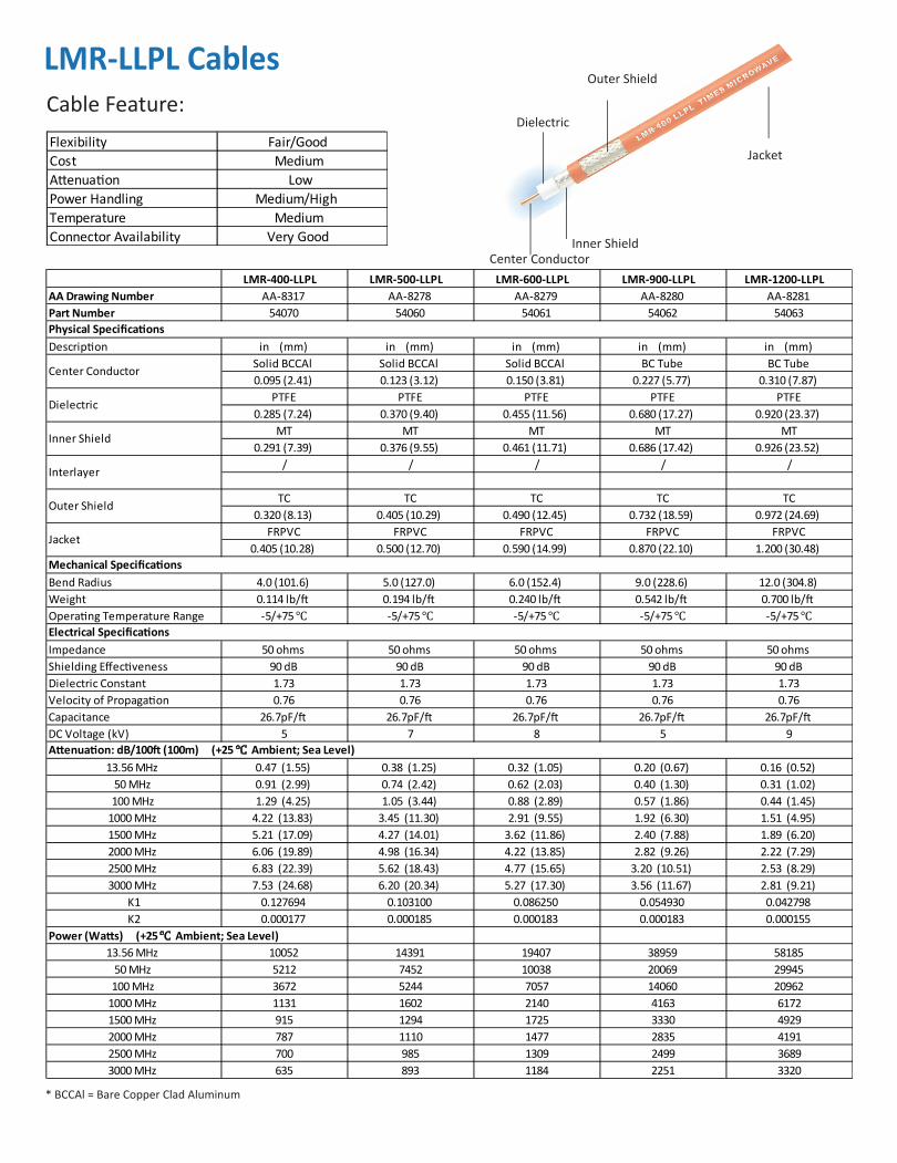
LMR-LLPL CablesCable Feature:
* BCCAl = Bare Copper Clad Aluminum
Jacket
Outer Shield
Inner Shield
Dielectric
Center Conductor
Flexibility Fair/GoodCost MediumAttenuation LowPower Handling Medium/HighTemperature MediumConnector Availability Very Good
LMR-400-LLPL LMR-500-LLPL LMR-600-LLPL LMR-900-LLPL LMR-1200-LLPLAA Drawing Number AA-8317 AA-8278 AA-8279 AA-8280 AA-8281Part Number 54070 54060 54061 54062 54063
Description in (mm) in (mm) in (mm) in (mm) in (mm)Solid BCCAl Solid BCCAl Solid BCCAl BC Tube BC Tube0.095 (2.41) 0.123 (3.12) 0.150 (3.81) 0.227 (5.77) 0.310 (7.87)
PTFE PTFE PTFE PTFE PTFE0.285 (7.24) 0.370 (9.40) 0.455 (11.56) 0.680 (17.27) 0.920 (23.37)
MT MT MT MT MT0.291 (7.39) 0.376 (9.55) 0.461 (11.71) 0.686 (17.42) 0.926 (23.52)
/ / / / /
TC TC TC TC TC0.320 (8.13) 0.405 (10.29) 0.490 (12.45) 0.732 (18.59) 0.972 (24.69)
FRPVC FRPVC FRPVC FRPVC FRPVC0.405 (10.28) 0.500 (12.70) 0.590 (14.99) 0.870 (22.10) 1.200 (30.48)
Bend Radius 4.0 (101.6) 5.0 (127.0) 6.0 (152.4) 9.0 (228.6) 12.0 (304.8)Weight 0.114 lb/ft 0.194 lb/ft 0.240 lb/ft 0.542 lb/ft 0.700 lb/ftOperating Temperature Range -5/+75℃ -5/+75℃ -5/+75℃ -5/+75℃ -5/+75℃
Impedance 50 ohms 50 ohms 50 ohms 50 ohms 50 ohmsShielding Effectiveness 90 dB 90 dB 90 dB 90 dB 90 dBDielectric Constant 1.73 1.73 1.73 1.73 1.73Velocity of Propagation 0.76 0.76 0.76 0.76 0.76Capacitance 26.7pF/ft 26.7pF/ft 26.7pF/ft 26.7pF/ft 26.7pF/ftDC Voltage (kV) 5 7 8 5 9
13.56 MHz 0.47 (1.55) 0.38 (1.25) 0.32 (1.05) 0.20 (0.67) 0.16 (0.52)50 MHz 0.91 (2.99) 0.74 (2.42) 0.62 (2.03) 0.40 (1.30) 0.31 (1.02)100 MHz 1.29 (4.25) 1.05 (3.44) 0.88 (2.89) 0.57 (1.86) 0.44 (1.45)
1000 MHz 4.22 (13.83) 3.45 (11.30) 2.91 (9.55) 1.92 (6.30) 1.51 (4.95)1500 MHz 5.21 (17.09) 4.27 (14.01) 3.62 (11.86) 2.40 (7.88) 1.89 (6.20)2000 MHz 6.06 (19.89) 4.98 (16.34) 4.22 (13.85) 2.82 (9.26) 2.22 (7.29)2500 MHz 6.83 (22.39) 5.62 (18.43) 4.77 (15.65) 3.20 (10.51) 2.53 (8.29)3000 MHz 7.53 (24.68) 6.20 (20.34) 5.27 (17.30) 3.56 (11.67) 2.81 (9.21)
K1 0.127694 0.103100 0.086250 0.054930 0.042798K2 0.000177 0.000185 0.000183 0.000183 0.000155
Power (Watts) (+25℃ Ambient; Sea Level)13.56 MHz 10052 14391 19407 38959 58185
50 MHz 5212 7452 10038 20069 29945100 MHz 3672 5244 7057 14060 20962
1000 MHz 1131 1602 2140 4163 61721500 MHz 915 1294 1725 3330 49292000 MHz 787 1110 1477 2835 41912500 MHz 700 985 1309 2499 36893000 MHz 635 893 1184 2251 3320
Physical Specifications
Mechanical Specifications
Attenuation: dB/100ft (100m) (+25℃ Ambient; Sea Level)
Electrical Specifications
Center Conductor
Dielectric
Inner Shield
Interlayer
Outer Shield
Jacket

RG CablesCable Feature:
* SC = Silver Plated Copper* BC = Bare Copper
Flexibility Good/Very GoodCost Medium/LowAttenuation MediumPower Handling Medium/HighTemperature MediumConnector Availability Medium
RG-393 RG-217 RG-177 RG-218 RG-220AA Drawing Number AA-3420 AA-3410 AA-3404 AA-3411 AA-6002Part Number 51509 41511 41506 41512 41579
Description in (mm) in (mm) in (mm) in (mm) in (mm)SC BC BC BC BC
0.094 (2.39) 0.106 (2.69) 0.195 (4.95) 0.195 (4.95) 0.260 (6.60)PTFE PE PE PE PE
0.285 (7.24) 0.370 (9.40) 0.680 (17.27) 0.680 (17.27) 0.910 (23.11)SC BC SC BC BC
0.295 (7.49) 0.403 (10.24) 0.709 (18.01) 0.726 (18.44) 0.956 (24.28)/ / / / /
SC BC SC / /0.330 (8.38) 0.436 (11.07) 0.738 (18.75)
FEP PVC PVC PVC PVC0.390 (9.91) 0.545 (13.84) 0.895 (22.73) 0.870 (22.10) 1.120 (28.45)
Bend Radius 2.0 (50.8) 5.5 (139.7) 9.0 (228.6) 9.0 (228.6) 12.0 (304.8)Weight 0.175 lb/ft 0.230 lb/ft 0.470 lb/ft 0.460 lb/ft 0.820 lb/ftOperating Temperature Range -55/+200℃ -40/+80℃ -40/+80℃ -40/+80℃ -40/+80℃Electrical SpecificationsImpedance 50 ohms 50 ohms 50 ohms 50 ohms 50 ohmsShielding Effectiveness 60 dB 60 dB 60 dB 40 dB 40 dBDielectric Constant 1.98 2.3 2.3 2.3 2.3Velocity of Propagation 0.71 0.659 0.659 0.659 0.659Capacitance 28.6pF/ft 30.8pF/ft 30.8pF/ft 30.8pF/ft 30.8pF/ftDC Voltage (kV) 1.9 5.8 8 8 10.5
13.56 MHz 0.76 (2.48) 0.61 (1.99) 0.35 (1.14) 0.35 (1.14) 0.24 (0.79)50 MHz 1.48 (4.86) 1.19 (3.90) 0.71 (2.31) 0.71 (2.31) 0.50 (1.63)100 MHz 2.13 (6.99) 1.71 (5.60) 1.05 (3.43) 1.05 (3.43) 0.74 (2.43)
1000 MHz 7.64 (25.05) 5.97 (19.59) 4.46 (14.63) 4.46 (14.63) 3.23 (10.60)1500 MHz 9.71 (31.85) 7.55 (24.75) 5.93 (19.44) 5.93 (19.44) 4.32 (14.16)2000 MHz 11.56 (37.92) 8.94 (29.32) 7.30 (23.93) 7.30 (23.93) 5.33 (17.49)2500 MHz 13.27 (43.53) 10.22 (33.51) 8.60 (28.22) 8.60 (28.22) 6.30 (20.68)3000 MHz 14.88 (48.80) 11.41 (37.43) 9.86 (32.35) 9.86 (32.35) 7.25 (23.77)
K1 0.200407 0.162200 0.087800 0.087800 0.061105K2 0.001300 0.000842 0.001685 0.001685 0.001300
13.56 MHz 19909 7230 16686 16888 2880050 MHz 10158 3704 8196 8295 14061100 MHz 7060 2582 5525 5592 9434
1000 MHz 1985 741 1302 1317 21681500 MHz 1564 588 981 993 16252000 MHz 1317 497 799 808 13172500 MHz 1149 435 678 687 11153000 MHz 1027 390 593 600 971
Physical Specifications
Mechanical Specifications
Attenuation: dB/100ft (100m) (+25℃ Ambient; Sea Level)
Power (Watts) (+25℃ Ambient; Sea Level)
Center Conductor
Dielectric
Inner Shield
Interlayer
Outer Shield
Jacket
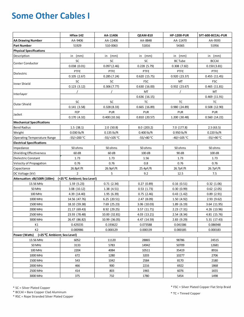
Some Other Cables I
* SC = Silver Plated Copper* BCCAl = Bare Copper Clad Aluminum* RSC = Rope Stranded Silver Plated Copper
* FSC = Silver Plated Copper Flat Strip Braid
* TC = Tinned Copper
HFlex-142 AA-11406 QEAM-810 HP-1200-PUR SFT-600-BCCAL-PURAA Drawing Number AA-9406 AA-11406 AA-8848 AA-11470 AA-9593Part Number 51929 510-0063 51816 54365 51956
Description in (mm) in (mm) in (mm) in (mm) in (mm)SC SC SC BC Tube BCCAl
0.038 (0.01) 0.097 (2.46) 0.228 (5.79) 0.308 (7.82) 0.150 (3.81)PTFE PTFE PTFE PTFE PTFE
0.105 (2.67) 0.285 (7.24) 0.620 (15.75) 0.920 (23.37) 0.455 (11.45)SC SC FSC MT FSC
0.123 (3.12) 0.306 (7.77) 0.630 (16.00) 0.932 (23.67) 0.465 (11.81)/ / MT / MT
0.636 (16.15) 0.469 (11.91)SC SC TC TC TC
0.141 (3.58) 0.328 (8.33) 0.665 (16.89) 0.980 (24.89) 0.508 (12.90)FEP PUR PUR PUR PUR
0.170 (4.32) 0.400 (10.16) 0.810 (20.57) 1.200 (30.48) 0.560 (14.22)
Bend Radius 1.5 (38.1) 2.0 (50.8) 8.0 (203.2) 7.0 (177.8) 2.5 (63.5)Weight 0.030 lb/ft 0.135 lb/ft 0.400 lb/ft 0.950 lb/ft 0.220 lb/ftOperating Temperature Range -55/+200℃ -55/+105℃ -55/+80℃ -40/+105℃ -55/+90℃
Impedance 50 ohms 50 ohms 50 ohms 50 ohms 50 ohmsShielding Effectiveness 60 dB 60 dB 100 dB 90 dB 100 dBDielectric Constant 1.73 1.73 1.56 1.73 1.73Velocity of Propagation 0.76 0.76 0.8 0.76 0.76Capacitance 26.8pF/ft 26.9pF/ft 25.4pF/ft 26.7pF/ft 26.7pF/ftDC Voltage (kV) 2 5 9.2 12.5 7.5
13.56 MHz 1.59 (5.23) 0.71 (2.34) 0.27 (0.89) 0.16 (0.51) 0.32 (1.06)50 MHz 3.08 (10.12) 1.38 (4.51) 0.53 (1.73) 0.30 (0.99) 0.62 (2.05)100 MHz 4.39 (14.40) 1.95 (6.39) 0.75 (2.46) 0.43 (1.42) 0.89 (2.91)
1000 MHz 14.56 (47.76) 6.25 (20.51) 2.47 (8.09) 1.50 (4.92) 2.93 (9.62)1500 MHz 18.10 (59.38) 7.69 (25.23) 3.06 (10.03) 1.89 (6.19) 3.64 (11.95)2000 MHz 21.17 (69.43) 8.92 (29.25) 3.57 (11.71) 2.23 (7.31) 4.26 (13.96)2500 MHz 23.93 (78.48) 10.00 (32.81) 4.03 (13.21) 2.54 (8.34) 4.81 (15.76)3000 MHz 26.47 (86.82) 10.99 (36.05) 4.47 (14.59) 2.83 (9.29) 5.31 (17.43)
K1 0.429235 0.193622 0.073588 0.041586 0.086948K2 0.000986 0.000129 0.000139 0.000185 0.000183
13.56 MHz 6052 11120 28865 98786 2451550 MHz 3133 5783 14942 50709 12681100 MHz 2204 4084 10511 35419 8916
1000 MHz 672 1280 3203 10277 27061500 MHz 543 1042 2584 8170 21802000 MHz 466 900 2216 6922 18682500 MHz 414 803 1965 6076 16553000 MHz 375 732 1780 5454 1498
Physical Specifications
Mechanical Specifications
Electrical Specifications
Attenuation: dB/100ft (100m) (+25℃ Ambient; Sea Level)
Power (Watts) (+25℃ Ambient; Sea Level)
Center Conductor
Dielectric
Inner Shield
Interlayer
Outer Shield
Jacket

Some Other Cables II
* SC = Silver Plated Copper
* BCCAl = Bare Copper Clad Aluminum* RSC = Rope Stranded Silver Plated Copper
* FSC = Silver Plated Copper Flat Strip Braid* TC = Tinned Copper
AA-11222 AA-11223 AA-9193 SFT-600-BCCAL LMR-1700-DB-TPVAA Drawing Number AA-11222 AA-11223 AA-9193 AA-8980 AA-11629Part Number 510-0042 510-0043 51887 51839 54376
Description in (mm) in (mm) in (mm) in (mm) in (mm)RSC RSC RSC BC BC Tube
0.160 (4.06) 0.160 (4.06) 0.160 (4.06) 0.150 (3.81) 0.516 (13.11)PTFE PTFE PTFE PTFE PE
0.455 (11.56) 0.455 (11.56) 0.455 (11.56) 0.455 (11.56) 1.35 (34.29)FSC SC SC SC APA
0.465 (11.81) 0.478 (12.14) 0.478 (12.14) 0.465 (11.81) 1.356 (34.44)MT / / APT /
0.469 (11.91) 0.469 (11.91)TC SC SC TC TC
0.508 (12.90) 0.501 (12.73) 0.501 (12.73) 0.508 (12.90) 1.402 (35.61)PUR PUR FEP FEP TPV
0.560 (14.22) 0.560 (14.22) 0.555 (14.10) 0.560 (14.22) 1.600 (40.64)
Bend Radius 2.5 (63.5) 2.5 (63.5) 2.5 (63.5) 2.5 (63.5) 13.5 (342.9)Weight 0.300 lb/ft 0.285 lb/ft 0.260 lb/ft 0.235 lb/ft 0.68 lb/ftOperating Temperature Range -55/+105℃ -55/+105℃ -55/+200℃ -55/+200℃ -50/+105℃
Impedance 50 ohms 50 ohms 50 ohms 50 ohms 50 ohmsShielding Effectiveness 100 dB 60 dB 60 dB 100 dB 90 dBDielectric Constant 1.73 1.73 1.73 1.73 1.26Velocity of Propagation 0.76 0.76 0.76 0.76 0.89Capacitance 26.7pF/ft 26.7pF/ft 26.7pF/ft 26.7pF/ft 22.8pF/ftDC Voltage (kV) 8 8 8 6 9
13.56 MHz 0.38 (1.24) 0.46 (1.51) 0.46 (1.51) 0.32 (1.06) 0.10 (0.33)50 MHz 0.73 (2.39) 0.89 (2.91) 0.89 (2.91) 0.62 (2.05) 0.20 (0.64)100 MHz 1.04 (3.40) 1.26 (4.14) 1.26 (4.14) 0.89 (2.91) 0.28 (0.93)
1000 MHz 3.40 (11.17) 4.11 (13.49) 4.11 (13.49) 2.93 (9.62) 0.99 (3.27)1500 MHz 4.22 (13.84) 5.09 (16.69) 5.09 (16.69) 3.64 (11.95) 1.26 (4.14)2000 MHz 4.92 (16.14) 5.92 (19.44) 5.93 (19.44) 4.26 (13.96) 1.50 (4.91)2500 MHz 5.55 (18.21) 6.67 (21.89) 6.67 (21.89) 4.81 (15.76) 1.71 (5.62)3000 MHz 6.13 (20.10) 7.36 (24.13) 7.36 (24.13) 5.31 (17.43) 1.91 (6.28)
K1 0.101875 0.124310 0.124310 0.086948 0.026741K2 0.000183 0.000183 0.000183 0.000183 0.000150
13.56 MHz 26221 21996 46760 61389 8196550 MHz 13579 11404 24242 31756 41916100 MHz 9555 8033 17076 22326 29185
1000 MHz 2919 2471 5253 6775 82931500 MHz 2357 2000 4251 5460 65532000 MHz 2022 1719 3654 4677 55252500 MHz 1794 1528 3248 4144 48303000 MHz 1626 1387 2948 3751 4320
Physical Specifications
Mechanical Specifications
Attenuation: dB/100ft (100m) (+25℃ Ambient; Sea Level)
Power (Watts) (+25℃ Ambient; Sea Level)
Electrical Specifications
Center Conductor
Dielectric
Inner Shield
Interlayer
Outer Shield
Jacket

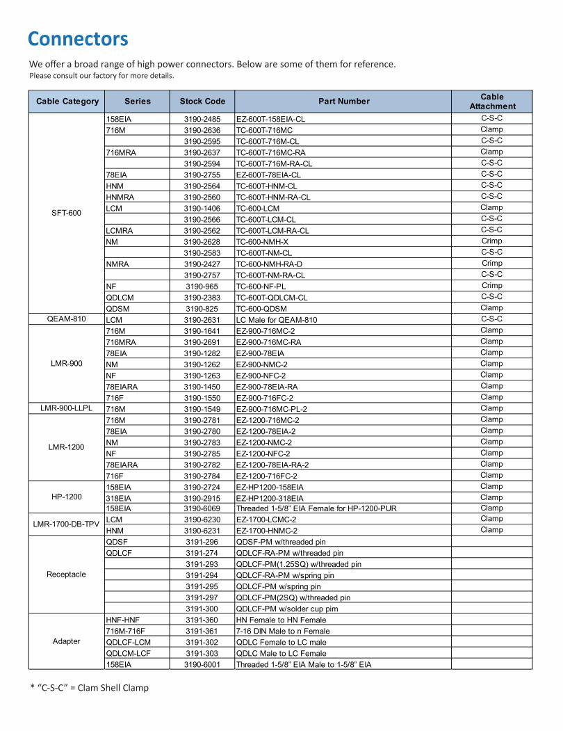
ConnectorsWe offer a broad range of high power connectors. Below are some of them for reference. Please consult our factory for more details.
Cable Category Series Stock Code Part Number Cable Attachment
158EIA 3190-2473 EZ-218-158EIA-CL C-S-C
716M 3190-2000 TC-218-716MC Clamp
78EIA 3190-2005 TC-218-78EIA Clamp
LCM 3190-1447 TC-218-LCM Clamp
LCMRA 3190-2587 TC-218-LCM-RA-CL C-S-C
NM 3190-2001 TC-218-NMC Clamp
SCM 3190-2003 TC-218-SCMC Clamp
CM 3190-2002 TC-218-CMC Clamp
1330M 3190-2004 TC-218-1330MC Clamp
716M 3190-2624 TC-226-716M-CL C-S-C
716MRA 3190-2625 TC-226-716M-RA-CL C-S-C
LCM 3190-2665 TC-226-LCM-CL C-S-C
LCMRA 3190-2666 TC-226-LCM-RA-CL C-S-C
NM 3190-2514 TC-500-NMH-X Crimp
NMRA 3190-2513 TC-500-NMH-RA-X Crimp
716M 3190-2597 TC-400-716M-X Crimp
3190-2692 TC-393-716M-CL C-S-C
716MRA 3190-2598 TC-400-716M-RA Crimp
3190-2693 TC-393-716M-RA-CL C-S-C
HNM 3190-2663 TC-393-HNM-CL C-S-C
HNMRA 3190-2559 TC-393-HNM-RA-CL C-S-C
LCM 3190-1412 TC-393-LCM Clamp
3190-2565 TC-393-LCM-CL C-S-C
LCMRA 3190-2561 TC-393-LCM-RA-CL C-S-C
NFBH 3190-1094 TC-393-NF-BH Crimp
3190-1401 TC-393T-NF-BH Crimp
NFPM 3190-1398 TC-393T-NF-PM Crimp
NM 3190-2626 TC-400-NMH-X Crimp
3190-2745 TC-393-NM-CL C-S-C
NMRA 3190-2293 TC-400-NMH-RA-D Crimp
3190-2754 TC-393-NM-RA-CL C-S-C
SCM 3190-2569 TC-393-SCM-CL C-S-C
SCMRA 3190-2570 TC-393-SCM-RA-CL C-S-C
CM 3190-922 TC-393T-CM Crimp
QDSM 3190-620 TC-400-QDSM Clamp
HNM 3190-2563 TC-320T-HNM-CL C-S-C
LCM 3190-2664 TC-320T-LCM-CL C-S-C
NM 3190-2578 TC-500-NM-PL-CL C-S-C
NMRA 3190-2579 TC-500-NM-RA-PL-CL C-S-C
716M 3190-2730 TC-500T-716MC Clamp
716MRA 3190-2729 TC-500T-716MC-RA Clamp
HNM 3190-2732 TC-500T-HNMC Clamp
HNMRA 3190-2731 TC-500T-HNMC-RA Clamp
SFT-500
HP-218
HP-226
RG-393
SFT-320
LMR-500-LLPL
ConnectorsWe offer a broad range of high power connectors. Below are some of them for reference. Please consult our factory for more details.
* “C-S-C” = Clam Shell Clamp
Cable Category Series Stock Code Part Number Cable Attachment
158EIA 3190-2485 EZ-600T-158EIA-CL C-S-C716M 3190-2636 TC-600T-716MC Clamp
3190-2595 TC-600T-716M-CL C-S-C716MRA 3190-2637 TC-600T-716MC-RA Clamp
3190-2594 TC-600T-716M-RA-CL C-S-C78EIA 3190-2755 EZ-600T-78EIA-CL C-S-CHNM 3190-2564 TC-600T-HNM-CL C-S-CHNMRA 3190-2560 TC-600T-HNM-RA-CL C-S-CLCM 3190-1406 TC-600-LCM Clamp
3190-2566 TC-600T-LCM-CL C-S-CLCMRA 3190-2562 TC-600T-LCM-RA-CL C-S-CNM 3190-2628 TC-600-NMH-X Crimp
3190-2583 TC-600T-NM-CL C-S-CNMRA 3190-2427 TC-600-NMH-RA-D Crimp
3190-2757 TC-600T-NM-RA-CL C-S-CNF 3190-965 TC-600-NF-PL CrimpQDLCM 3190-2383 TC-600T-QDLCM-CL C-S-CQDSM 3190-825 TC-600-QDSM Clamp
QEAM-810 LCM 3190-2631 LC Male for QEAM-810 C-S-C716M 3190-1641 EZ-900-716MC-2 Clamp716MRA 3190-2691 EZ-900-716MC-RA Clamp78EIA 3190-1282 EZ-900-78EIA ClampNM 3190-1262 EZ-900-NMC-2 ClampNF 3190-1263 EZ-900-NFC-2 Clamp78EIARA 3190-1450 EZ-900-78EIA-RA Clamp716F 3190-1550 EZ-900-716FC-2 Clamp
LMR-900-LLPL 716M 3190-1549 EZ-900-716MC-PL-2 Clamp716M 3190-2781 EZ-1200-716MC-2 Clamp78EIA 3190-2780 EZ-1200-78EIA-2 ClampNM 3190-2783 EZ-1200-NMC-2 ClampNF 3190-2785 EZ-1200-NFC-2 Clamp78EIARA 3190-2782 EZ-1200-78EIA-RA-2 Clamp716F 3190-2784 EZ-1200-716FC-2 Clamp158EIA 3190-2724 EZ-HP1200-158EIA Clamp318EIA 3190-2915 EZ-HP1200-318EIA Clamp158EIA 3190-6069 Threaded 1-5/8” EIA Female for HP-1200-PUR ClampLCM 3190-6230 EZ-1700-LCMC-2 ClampHNM 3190-6231 EZ-1700-HNMC-2 ClampQDSF 3191-296 QDSF-PM w/threaded pin QDLCF 3191-274 QDLCF-RA-PM w/threaded pin
3191-293 QDLCF-PM(1.25SQ) w/threaded pin 3191-294 QDLCF-RA-PM w/spring pin 3191-295 QDLCF-PM w/spring pin 3191-297 QDLCF-PM(2SQ) w/threaded pin 3191-300 QDLCF-PM w/solder cup pim
HNF-HNF 3191-360 HN Female to HN Female 716M-716F 3191-361 7-16 DIN Male to n Female QDLCF-LCM 3191-302 QDLC Female to LC male QDLCM-LCF 3191-303 QDLC Male to LC Female 158EIA 3190-6001 Threaded 1-5/8” EIA Male to 1-5/8” EIA
Adapter
Receptacle
LMR-1700-DB-TPV
SFT-600
LMR-900
LMR-1200
HP-1200
QDLC Male QDLC Female
Clam Shell Clamp Strain Relief
Clam Shell Clamp
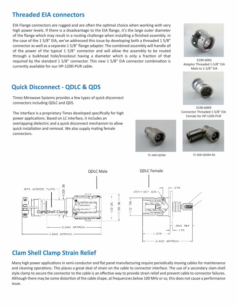
Quick Disconnect - QDLC & QDSTimes Mirowave Systems provides a few types of quick disconnect connectors including QDLC and QDS.
The interface is a proprietary Times developed specifically for high power applications. Based on LC interface, it includes an overlapping dielectric and a quick disconnect mechanism to allow quick installation and removal. We also supply mating female connectors.
EIA Flange connectors are rugged and are often the optimal choice when working with very high power levels. If there is a disadvantage to the EIA flange, it’s the large outer diameter of the flange which may result in a routing challenge when installing a finished assembly. In the case of the 1 5/8” EIA, we’ve addressed this issue by developing both a threaded 1 5/8” connector as well as a separate 1 5/8” flange adapter. The combined assembly will handle all of the power of the typical 1 5/8” connector and will allow the assembly to be routed through a bulkhead hole/knockout having a diameter which is only a fraction of that required by the standard 1 5/8” connector. This new 1 5/8” EIA connector combination is currently available for our HP-1200-PUR cable.
Threaded EIA connectors
Many high power applications in semi-conductor and flat panel manufacturing require periodically moving cables for maintenance and cleaning operations. This places a great deal of strain on the cable to connector interface. The use of a secondary clam-shell style clamp to secure the connector to the cable is an effective way to provide strain relief and prevent cable to connector failures. Although there may be some distortion of the cable shape, at frequencies below 100 MHz or so, this does not cause a performance issue.
TC-400-QDSM TC-600-QDSM-RA
3190-6001 Adaptor Threaded 1-5/8” EIA
Male to 1-5/8” EIA
3190-6069 Connector Threaded 1-5/8” EIA
Female for HP-1200-PUR

Selection of RF Coaxial Cable by Power HandlingElectrical losses in a coaxial cable result in the generation of heat in the center and outer conductors, as well as in the dielectric core. The power handling capability of a cable is related to the ability of the cable to dissipate this heat. The ultimate limiting factor in power handling is the maximum allowable operating temperature of the materials used in the cable, especially the dielectric. This is because most of the heat is generated at the center conductor of the cable. In general, the power handling capability of a given cable is inversely proportional to its attenuation, and directly related to its size. The other factor is the heat transfer properties of the cable, especially the dielectric.
Cable power ratings must be derated by correction factors for the ambient temperature, altitude and VSWR encountered in a particular application. High ambient temperature and high altitude reduce the power rating of a cable by impeding heat transfer out of the cable, VSWR reduces power rating by causing localized hot spots in the cable.
To select the cable construction for a particular requirement, determine the average input power at the highest frequency from system requirements. Then determine the effective average input power as follows:
Effective Power =
Temperature and altitude corrections are shown as:
Power Temperature Correction Factor:Power Altitude Correction Factor:VSWR
Correction Factor Multiplier K
VSWR correction factor =
1/2 (VSWR + VSWR) + 1/2 k (VSWR - VSWR)
Where k, is shown in the second Figure. Select a cable from the Attenuation and Power charts rated at this effective power level. Note that the peak power handling capability of a cable is related to the maximum operating voltage rating.
1 1
Times Microwave Systems offers the customized brackets to allow mounting of interlock switches.
Custom Interlock Bracket
Average Power x (VSWR correction) (Temp.correction) x (Alt.correction)
09/30/2016