1633 combustion controller manual - novatech … · 2 1633 combustion controller using this manual...
TRANSCRIPT

August 2009
Combustion Controller
Model 1633


August 2009 1633 Combustion Controller 1
CONTENTS 1 SPECIFICATIONS .......................................................................................................................... 3 2 DESCRIPTION .............................................................................................................................. 13 3 INSTALLING & COMMISSIONING .......................................................................................... 19 4 OPERATOR FUNCTIONS ........................................................................................................... 35 5 SETTING UP THE TRANSMITTER ........................................................................................... 41 6 MAINTENANCE ........................................................................................................................... 59 INDEX ........................................................................................................................................... 90 APPENDICES APPENDIX 1 CONSTITUENT VALUES FOR FUELS ........................................................................ 64 APPENDIX 2 PROBE OR SENSOR EMF TABLES ............................................................................. 65 APPENDIX 3 % OXYGEN SCALE TO LOGARITHMIC .................................................................... 67 APPENDIX 4 SAMPLE LOG PRINT OUT ........................................................................................... 68 APPENDIX 5 CIRCUIT SCHEMATICS ................................................................................................ 69 APPENDIX 6 MODBUS™ REGISTER MAP AND APPLICATION NOTES ..................................... 78 APPENDIX 7 COMMISSIONING A 1633 COMBUSTION CONTROLLER ...................................... 82 APPENDIX 8 1633 COMBUSTION CONTROLLER CHARACTERISATION TABLE .................... 89 Note: This manual includes software modifications up to Version 3.24, October, 2005
© Copyright NOVATECH CONTROLS PTY. LTD. - 1996 - 2008 This manual is part of the product sold by Novatech Controls Pty. Ltd. ("Novatech Controls") and is provided to the customer subject to Novatech Controls' conditions of sale, a copy of which is set out herein. Novatech Controls' liability for the product including the contents of this manual is as set out in the conditions of sale. All maintenance and service of the product should be carried out by Novatech Controls' authorised dealers. This manual is intended only to assist the reader in the use of the products. This manual is provided in good faith but Novatech Controls does not warrant or represent that the contents of this manual are correct or accurate. It is the responsibility of the owner of the product to ensure users take care in familiarising themselves in the use, operation and performance of the product. The product, including this manual and products for use with it, are subject to continuous developments and improvement by Novatech Controls. All information of a technical nature and particulars of the product and its use (including the information in this manual) may be changed by Novatech Controls at any time without notice and without incurring any obligation. A list of details of any amendments or revisions to this manual can be obtained upon request from Novatech Controls. Novatech Controls welcome comments and suggestions relating to the product including this manual. Neither the whole nor any part of the information contained in, or the product described in, this manual may be adapted or reproduced in any material form except with the prior written approval of Novatech Controls Pty. Ltd. All correspondence should be addressed to: Technical Enquires Novatech Controls Pty Ltd 309 Reserve Road Cheltenham Victoria 3192 Phone: Melbourne +61 3 9585 2833 Australia Fax: Melbourne +61 3 9585 2844 Website: http://www.novatech.com.au/

August 2009 2 1633 Combustion Controller
USING THIS MANUAL The Novatech 1633 Oxygen Transmitter has a variety of user-selectable functions. They are simple to use because each selection is menu driven. For options you are not sure about; read the manual on that particular item. Please read the safety information below and the ‘Installation’ section before connecting power to the analyser.
CAUTION 1 The probe heater is supplied with mains voltage. This supply has electrical shock danger to maintenance personnel. Always isolate the analyser before working with the probe . The EARTH wire (green) from a heated probe must ALWAYS be connected to earth.
CAUTION 2 Combustion or atmosphere control systems can be dangerous. Burners must be mechanically set up so that in the worst case of equipment failure, the system cannot generate explosive atmospheres. This danger is normally avoided with flue gas trim systems by adjustment so that in the case of failure the appliance will not generate CO in excess of 400 ppm in the flue. The CO level in the flue should be measured with a separate CO instrument, normally an infrared or cell type.
CAUTION 3 The oxygen sensor is heated to over 700°C (1300°F) and is a source of ignition. Since raw fuel leaks can occur during burner shutdown, the analyser has an interlocking relay that removes power from the probe heater when the main fuel shut-off valve power is off. If this configuration does not suit or if it is possible for raw fuel to come into contact with a hot oxygen probe then the Model 1633 analyser with a heated probe will not be safe in your application. An unheated probe can be utilised in such applications, however the oxygen readings are valid only above 650°C (1200°F).
CAUTION 4 The reducing oxygen signal from the analyser and the associated alarm relay can be used as an explosive warning or trip. This measurement assumes complete combustion. If incomplete combustion is possible then this signal will read less reducing and should not be used as an alarm or trip. A true excess combustibles analyser, normally incorporating a catalyst or thermal conductivity bridge, would be more appropriate where incomplete combustion is possible. Also read the probe electrical shock caution in Section 2.5 and the probe heater interlock caution in Section 3.6.
CAUTION 5 If an external pressure transducer is used to feed the process pressure to the analyser for pressure compensation, it is essential that the pressure transducer is accurate and reliable. An incorrect reading of pressure will result in an incorrect reading of oxygen. It is therefore possible that an explosive level of fuel could be calculated in the analyser as a safe mixture.
CAUTION 6 FIL-3 filter. If the optional FIL-3 has been fitted to the 1231 probe in this installation, please read the Important Notice in section 1.2.

August 2009 1633 Combustion Controller 3
1 SPECIFICATIONS Section Number 1.1 MODEL 1633 COMBUSTION CONTROLLER ............................................................................. 4 1.2 SERIES 1230 OXYGEN PROBES & SENSORS ............................................................................ 7 1.3 PURGE & CALIBRATION CHECK ACCESSORIES .................................................................. 11 1.4 FILTER PURGE PRESSURE SWITCH ........................................................................................ 12
August 2009 4 1633 Combustion Controller
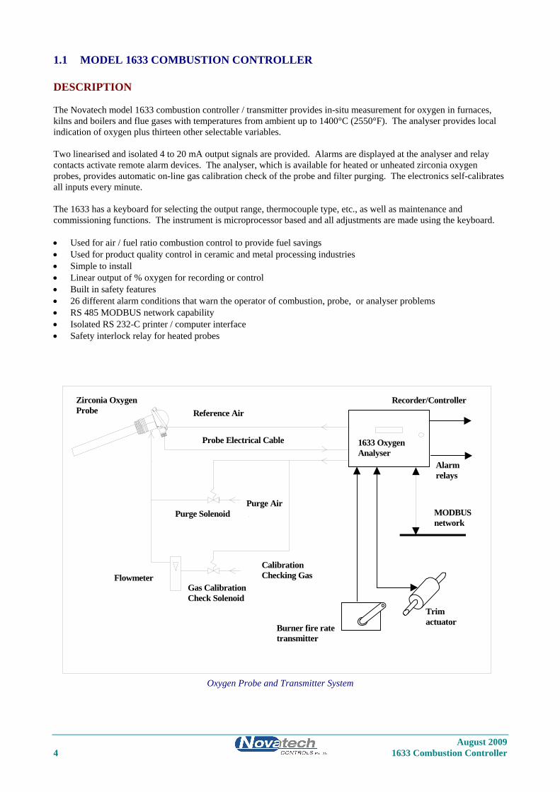
1.1 MODEL 1633 COMBUSTION CONTROLLER DESCRIPTION The Novatech model 1633 combustion controller / transmitter provides in-situ measurement for oxygen in furnaces, kilns and boilers and flue gases with temperatures from ambient up to 1400°C (2550°F). The analyser provides local indication of oxygen plus thirteen other selectable variables. Two linearised and isolated 4 to 20 mA output signals are provided. Alarms are displayed at the analyser and relay contacts activate remote alarm devices. The analyser, which is available for heated or unheated zirconia oxygen probes, provides automatic on-line gas calibration check of the probe and filter purging. The electronics self-calibrates all inputs every minute. The 1633 has a keyboard for selecting the output range, thermocouple type, etc., as well as maintenance and commissioning functions. The instrument is microprocessor based and all adjustments are made using the keyboard. • Used for air / fuel ratio combustion control to provide fuel savings • Used for product quality control in ceramic and metal processing industries • Simple to install • Linear output of % oxygen for recording or control • Built in safety features • 26 different alarm conditions that warn the operator of combustion, probe, or analyser problems • RS 485 MODBUS network capability • Isolated RS 232-C printer / computer interface • Safety interlock relay for heated probes
Oxygen Probe and Transmitter System
REF
1633 OxygenAnalyser
MODBUSnetwork
Reference Air
Purge Air
FlowmeterCalibrationChecking Gas
Gas CalibrationCheck Solenoid
Purge Solenoid
Zirconia OxygenProbe
Recorder/Controller
Alarmrelays
Probe Electrical Cable
Trimactuator
Burner fire ratetransmitter

August 2009 1633 Combustion Controller 5
SPECIFICATIONS Inputs • Zirconia oxygen probe, heated or unheated • Burner feedback transmitter (Novatech BFT-20 or equivalent) • Trim control actuator feedback • Furnace, kiln or flue thermocouple, field selectable as type K or R. • Main flame established safety interlock (for heated probes only) • Purge pressure switch • Dual Fuel selector • Remote alarm accept Outputs • Two linearised 4 to 20 mA DC outputs, max. load 1000Ω. • Mains voltage up / down trim actuator • Common alarm relay • Three other alarm relays with field selectable functions Computer • MODBUS RS 485 network, or RS 232-C for connection of a computer terminal or printer for diagnostics of the
analyser, probe, sensor or combustion process. Range of Output 1 Field selectable from the following: Output Selection Range Linear oxygen 0.0 to 0.1% oxygen to 0.0 to 100.0 % oxygen Log oxygen 0.1 to 20 % oxygen, fixed Reducing 10-1 to 10-30 % oxygen, fixed Reducing 1ppm to 100 % oxygen, fixed Linear oxygen, very low range -10% to 100.0 % oxygen, fixed Deficiency 0.00 to 0.01 % (100ppm) to 0.00 to 10.00 % oxygen Range of Output 2 Field selectable from the following: Output Zero Range Span Range Oxygen Sensor EMF 0 to 1100 mV in 100 mV steps 1000 to 1300 mV in 100 mV steps Log Oxygen 0.1% O2 Fixed 20% O2 Fixed Aux. Temperature 0 to 100°C (32 to 210°F) in 1 degree steps 100 to 1400°C (210 to 2550°F) in 100 degree steps Linear Oxygen 0% oxygen, fixed 1 to 100%
Reducing Oxygen 10+2 (100%) to 10-10 % oxygen in one 10-3 to 10-30 % oxygen in decade steps, non-overlapping one decade steps. Min span 2 decades. Efficiency 0 % Fixed 100 % Fixed Carbon Dioxide 0 to 10 % 2 to 20 % Oxygen Deficiency 0 to 20% O2 deficiency 0 to 100% O2 excess Combustibles % 0 fixed 0.5 to 2.0 %

August 2009 6 1633 Combustion Controller
Range of Indication, Upper Line • Auto ranging from 10-30 to 100% 02 Indication Choice, Lower Line Any or all of the following can be selected for lower line display: • Run Hours since last service • Date of last service • Burner firing rate • Trim actuator position • Oxygen probe EMF • Oxygen probe temperature • Auxiliary temperature • Oxygen probe impedance • Ambient temperature • Boiler efficiency • Oxygen deficiency • Combustibles % • Carbon dioxide The oxygen deficiency output can be used in the same way as a combustibles analyser to signal the extent of reducing conditions of combustion processes. Accuracy • ±1% of actual measured oxygen value with a repeatability of ±0.5% of measured value. Relay Contacts • 0.5A 24 VAC, 1A 36 VDC Environmental Rating • Operating Temperature: -25 to 55°C (-15 to 130°F) • Relative Humidity: 5 to 95% (non-condensing) • Vibration: 10 to 150Hz (2g peak) Power Requirements • 240 or 110V, 50/60 Hz, 105 VA (heated probe) • 240 or 110V, 50/60 Hz, 5 VA (unheated probe) Weight • Analyser, 3.75 kg (10 lbs.) Dimensions • 280mm (11”) W x 180mm (7”) H x 95mm (3.75”) D Degree of Protection • IP65 without reference air pump • IP54 with reference air pump Mounting • Suitable for wall or surface mounting.

August 2009 1633 Combustion Controller 7
1.2 SERIES 1230 OXYGEN PROBES & SENSORS DESCRIPTION Novatech series 1230 oxygen probes and sensors employ state-of-the-art zirconia sensors and advanced materials, which provide the following benefits: • Improved control due to fast response time to typically less than four seconds • Cost-efficient design provides improved reliability • Longer-life probes with greater resistance to corrosion from sulphur and zinc contaminants in flue gas • Low cost allows maintenance by replacement • Reduced probe breakage due to greater resistance to thermal shock and mechanical damage during installation and
start-up • Series 1230 probes are simple to install and maintain. All models provide direct measurement of oxygen level.
On-line automatic calibration check is available if required. Probes may be used with Novatech combustion controllers and some analyser models from other manufacturers.
All Novatech oxygen probes are designed and manufactured to exacting standards of performance and reliability. Series 1230 probes are the result of extensive research and development by Novatech, industry and government agencies. Novatech Controls provides application and after sales support for oxygen probes, sensors and analysers, worldwide.
Model 1231 Heated Oxygen Probe
Model 1232 Unheated Oxygen Probe

August 2009 8 1633 Combustion Controller
E X HA U ST
1234 OXYGEN SENSOR
N OV A T EC H C ON T R OL S
CABLE GLAN D
ID LABEL
EXHAUST 1/4" NPT FEMALE
GAS INLET 1/4" TUBE ELBOW
Model 1234 Oxygen Sensor
STANDARD PROBE ‘U’ LENGTHS 1231 1232 250 mm (10”) 500 mm (20”) 350 mm (14”) 750 mm (30”) 500 mm (20”) 1000 mm (40”) 750 mm (30”) 1500 mm (60”) 1000 mm (40”) 1500 mm (60”) 2000 mm (80”)
Ordering Information 1. Probe insertion length (from process end of mounting thread to probe sensing tip). 2. Mounting thread (process connection), BSP or NPT (for size of thread refer to specifications). 3. Lagging extension length, if required. 4. If model 1232 probe, state preferred thermocouple type (refer to specifications).

August 2009 1633 Combustion Controller 9
Important Notice Regarding 1231 Probe Option - FIL-3
WARNING: The only identifiable standard for flame arresters for general use is British Standard BS7224:1990. British Standard BS7224:1990 refers to an operating environment up to 200 Degrees Centigrade. The FIL-3 device optionally fitted to 1231 Heated Zirconia Probes (the “Probes" or "Probe") operate in an environment considerably greater than 200 Degrees Centigrade. Therefore, we know of no Australian, British or USA standard applicable to flame arresters or their testing above 200 degrees Centigrade. Consequently, the FIL-3 device cannot be certified as a safety device. The probe is only one of several potential sources of ignition. Extreme care is required when using the probes during the start up processes of a combustion appliance. The Novatech Burner Interlock Relay facility, which is a standard part of the Novatech Analyser, is designed to be wired to the main safety shut-off fuel valves in a way that can shutdown the probe heater when the fuel valves are closed. The risk of ignition of flammable gas mixture at the hot end of the Probe can only be minimised by correct use, maintenance and operation of the FIL-3 device. The user of the FIL-3 device is responsible for verification and maintenance and correct use and operation of the FIL-3 device. THE USER AGREES THAT IT USES THE PROBE AND THE FIL-3 DEVICE AT ITS SOLE RISK. NOVATECH CONTROLS PTY LTD, TO THE FULL EXTENT PERMITTED BY LAW, GIVES NO WARRANTIES OR ASSURANCES AND EXCLUDES ALL LIABILITY (INCLUDING LIABILITY FOR NEGLIGENCE) IN RELATION TO THE PROBE AND THE FIL-3 DEVICE. The user must ensure that it correctly follows all instructions in relation to the Probe and FIL-3 device, correctly understands the specifications of the Probe and FIL-3 device and ensures that the Probe and FIL-3 device are regularly inspected and maintained. FIL-3 equipped Probes should be inspected at least once a year for corrosion and more frequently is there is any reason to suspect that corrosion may have occurred.
August 2009 10 1633 Combustion Controller
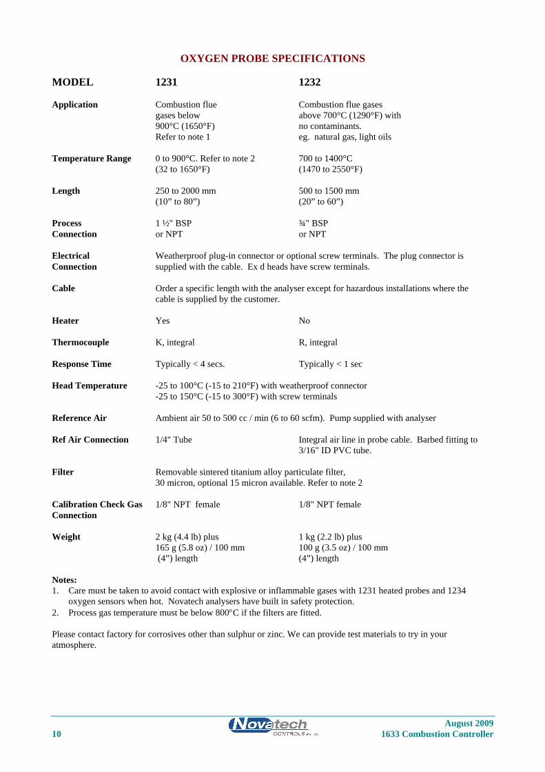
OXYGEN PROBE SPECIFICATIONS MODEL 1231 1232 Application Combustion flue Combustion flue gases gases below above 700°C (1290°F) with 900°C (1650°F) no contaminants. Refer to note 1 eg. natural gas, light oils Temperature Range 0 to 900°C. Refer to note 2 700 to 1400°C (32 to 1650°F) (1470 to 2550°F) Length 250 to 2000 mm 500 to 1500 mm (10” to 80”) (20” to 60”) Process 1 ½" BSP ¾" BSP Connection or NPT or NPT Electrical Weatherproof plug-in connector or optional screw terminals. The plug connector is Connection supplied with the cable. Ex d heads have screw terminals. Cable Order a specific length with the analyser except for hazardous installations where the cable is supplied by the customer. Heater Yes No Thermocouple K, integral R, integral Response Time Typically < 4 secs. Typically < 1 sec Head Temperature -25 to 100°C (-15 to 210°F) with weatherproof connector -25 to 150°C (-15 to 300°F) with screw terminals Reference Air Ambient air 50 to 500 cc / min (6 to 60 scfm). Pump supplied with analyser Ref Air Connection 1/4" Tube Integral air line in probe cable. Barbed fitting to 3/16" ID PVC tube. Filter Removable sintered titanium alloy particulate filter, 30 micron, optional 15 micron available. Refer to note 2 Calibration Check Gas 1/8" NPT female 1/8" NPT female Connection Weight 2 kg (4.4 lb) plus 1 kg (2.2 lb) plus 165 g (5.8 oz) / 100 mm 100 g (3.5 oz) / 100 mm (4”) length (4”) length Notes: 1. Care must be taken to avoid contact with explosive or inflammable gases with 1231 heated probes and 1234
oxygen sensors when hot. Novatech analysers have built in safety protection. 2. Process gas temperature must be below 800°C if the filters are fitted. Please contact factory for corrosives other than sulphur or zinc. We can provide test materials to try in your atmosphere.

August 2009 1633 Combustion Controller 11
OXYGEN PROBE MODEL SELECTION GUIDE Heated probes-temperature range 0-900°C (1650°F). 1231 - U Length - Outer - Internal - Mounting Sheath Thermocouple Thread Basic model 2. 250mm (10”) 1. 316 SS max 850°C 1. Type K max 900°C 1. 1 ½ BSP 3. 500mm (20”) (1560°F) (1650°F) 2. 1 ½ NPT 4. 750mm (30”) 2. Inconel *(1) 5. 1000mm (40”) 6. 1500mm (60”) 7. 2000mm (80”) *Note: (1) The Inconel option has all inconel wetted parts except for the ceramic sensor and viton ‘o’ rings. Unheated probes for clean gases-temperature range 700-1400°C (1290-2550°F). 1232 - U Length - Outer Sheath - Internal Thermocouple - Mounting Thread Basic model 3. 500mm (20”) 1. 253 MA-max 1000°C 1. Nil *(2) 1. 3/4” BSP fixed 4. 750mm (30”) (1830°F) 4. Type R max 1400°C 2. 3/4” NPT fixed 5. 1000mm (40”) 3. High Purity Alumina (2550°F) 6. 1500mm (60”) max 1300°C (2370°F) Horizontal max 1400°C (2550°F) Vertical 4. 446 SS max 1000°C (1830°F)
1234 SENSOR SPECIFICATIONS Range of measurement: 1 ppm to 100% oxygen Output: EMF = 2.154.10-2.T.loge (0.209 / oxygen level of the sample) Accuracy: ± 1% Thermocouple: Type K Heater: 110 VAC 50/60Hz, 100 watts Heater proportional band: 80°C (175°F) Speed of Response: Less than 100 milliseconds Sample flow rate: 1 to 5 litres / minute (120 to 600 scfm) Differential Pressure: 80 to 800 mm (3 to 30”) WG gives a flow of 1 to 5 litres / min (120 to 600 scfm) Process Connections: 1/4” NPT female, inlet and outlet Dimensions: 300 mm (11.81”) high by 125 mm (4.92”) wide by 88 mm (3.46”) deep Weight: 2.2 Kg (4.85 lbs.)
1.3 PURGE & CALIBRATION CHECK ACCESSORIES Due to the absolute measurement characteristics of zirconia sensors and the self-calibration features of Novatech analysers, probe calibration checks with calibrated gas are not normally required. In some installations however, automatic gas calibration checks are required by Environmental Protection Authorities and by engineering management in Power Stations, Oil Refineries and similar large end users. Novatech probes and analysers provide a ready method of connecting on-line calibration check gases. They provide on-line automatic checking of probe and analyser calibration, as well as a probe purge facility. The absolute characteristics of zirconia sensors require only one calibration check gas to properly check the probe’s performance. Where required however, the dual gas calibration check facility can be utilised. Dirty flue gas applications often require the back purge facility to keep a probe filter free from blockage. (In these applications, it is more reliable to install probes pointing vertically downwards with no filter). Purge and calibration check solenoid valves can be operated manually or automatically from a 1633 analyser. The external components required for automatic / manual gas calibration checking are: • A calibration check gas flow meter / regulator • A mains voltage (240 or 110 VAC) solenoid valve for each calibration check gas

August 2009 12 1633 Combustion Controller
The external components required for automatic / manual purging are: • A mains voltage (240 or 110 VAC) purge solenoid valve • A purge pressure switch, 0 to 35 kPa (0 to 5 psi), to test for filter blockage. The user should supply: • Span gas cylinder(s), typically 2% oxygen in nitrogen or a similar percentage of O2 close to the normal level in the
gas stream being measured, to ensure fast recovery. • A 100 kPa (15 psi) clean and dry instrument air supply when filter purging is required.
1.4 FILTER PURGE PRESSURE SWITCH To automatically sense a blocked probe filter, a pressure sensor should be connected to the ‘purge’ line to the probe ‘cal’ port. It should be adjusted so that it energises just above the purge pressure with a new or clean filter installed. The switch contacts should be connected to terminals 12 & 13 (PURGE FL SWITCH). If the filter is still blocked or partly blocked after an auto purge cycle, the pressure switch will energise and cause a ‘Probe Filter Blocked’ alarm. The contacts must be normally closed. The pressure switch should have an adjustable range of 0 to 100 kPa (0 to 15 psi).

August 2009 1633 Combustion Controller 13
2 DESCRIPTION Section Number 2.1 THE ZIRCONIA SENSOR ............................................................................................................. 14 2.2 THE OXYGEN PROBE ................................................................................................................. 15 2.3 THE ANALYSER ........................................................................................................................... 15 2.4 ALARMS ........................................................................................................................................ 15 2.5 HEATER ......................................................................................................................................... 15 2.6 APPLICATIONS WHERE SENSING POINT IS NOT AT ATMOSPHERIC PRESSURE ......... 15 2.7 OXYGEN SENSOR IMPEDANCE ............................................................................................... 16 2.8 AUTO CALIBRATION - ELECTRONICS ................................................................................... 16 2.9 AUTO CALIBRATION CHECKING - PROBES .......................................................................... 16 2.10 AUTO PURGE ................................................................................................................................ 16 2.11 RS 485 MODBUS NETWORK & RS 232C PORT ....................................................................... 17 2.12 AUXILIARY TEMPERATURE THERMOCOUPLE ................................................................... 17 2.13 WATCHDOG TIMER .................................................................................................................... 17 2.14 BACK-UP BATTERY .................................................................................................................... 17

August 2009 14 1633 Combustion Controller
DESCRIPTION
2.1 THE ZIRCONIA SENSOR The analyser input is provided for a solid electrolyte oxygen probe, which contains a zirconia element and thermocouple. The probe is designed to be inserted into a boiler or furnace exit gas flue or similar process. A 1234 sensor is designed to be installed outside of the flue or process. Sampling lines and filters are not required for in-situ probes but they are required for 1234 sensors. When a sampling line is required, the sample flows to the sensor under process pressure in most applications. In applications where the process pressure is negative or neutral, a suction pump will be required. A reference air pump is provided in the 1633 combustion controller. The internal construction of a probe is shown as follows.
Internal electrode wire
Ziconia Disc
ThermocoupleWires
Electrode Material
(required onlyHeater
with heatedprobes)
External Wire Contact
ThermocoupleJunction
Internal Electrode
Four-Bore ThermocoupleInsulating Tubing
Alumina Tube
Schematic View of a Zirconia Sensor Assembly
The heater control in the 1633 analysers consists of a time proportioning temperature controller and solid state relay so that the thermocouple junction is controlled to over 700°C (1300°F). Probes operating in a combustion environment above 650°C (1200°F) do not require a heater. When exposed to different oxygen partial pressures at the outside and inside of the sensor, an EMF (E) is developed which obeys the Nernst equation:
( )( ) ⎟⎟
⎠
⎞⎜⎜⎝
⎛=
outsidePOinsidePO
FRTmillivoltsE e
2
2log4
)(
Where T is the temperature (K) at the disc (>650°C (1200°F)), R is the gas constant, F is the Faraday constant and (PO2) INSIDE and (PO2) OUTSIDE are the oxygen partial pressures at the inner and outer electrodes, respectively, with the higher oxygen partial pressure electrode being positive. If dry air at atmospheric pressure, (21 % oxygen) is used as a reference gas at the inner electrode, the following equations are obtained:
( )outsidePOTmillivotsE e
2
2 21.0log10154.2)( −×=
Transposing this equation
( ) ( )T
ERATMoutsideO 421.46exp21.0% 2−
=
The 1633 transmitter solves this equation which is valid above 650°C (1200°F). The probe heater, or the process maintains the sensor temperature at this level.

August 2009 1633 Combustion Controller 15
2.2 THE OXYGEN PROBE The probe assembly provides a means of exposing the zirconia sensor to the atmosphere to be measured with sensor, thermocouple and heater wires connected via the analyser lead. Reference air is fed via the plug for unheated probes and via a separate gas thread connection for heated probes. Connections are provided on probes for an in-situ gas calibration check. A cleaning purge of air can be admitted via the calibration gas check entry. The outer sheath of probes can be metal or ceramic, depending on the application. Calibration check can be achieved on 1234 sensors using a three way solenoid which blocks the sample and at the same time admits a calibration check gas to the sensor. Purging a probe for any dust build up can be achieved in the same way. In-situ zirconia oxygen probes will give a lower oxygen reading than a sampled gas measurement on a chromatograph or paramagnetic analyser because the flue gas contains a significant level of water vapour and a sampling system removes the water vapour through condensation. The oxygen content then appears as a higher percentage of the remaining gas. For example: If the gas contained five parts oxygen and fifteen parts moisture, removing the moisture would leave the oxygen at 5.88%. This phenomena will depend on the fuel and the completeness of combustion. They are common to all in-situ oxygen sensors.
2.3 THE ANALYSER The top line of the analyser display will read oxygen in either % or ppm. The 1633 analyser is a transmitter with two 4 to 20 mA outputs. One output is linear oxygen with selectable span. The second output can be selected as oxygen deficiency, combustibles, auxiliary temperature, reducing oxygen, percent carbon dioxide, sensor EMF or a logarithmic oxygen range. Four alarm relays are provided. Refer to the sections 4.2 and 4.3 for more details. The 1633 analyser is designed to operate with one heated or unheated zirconia probe in a combustion process. The analyser will alarm when there is a high difference between the measured oxygen level and the required set point oxygen. It can transmit and display the oxygen signal. In addition, a fixed oxygen set point, or a set point characterised to the burner firing rate can be used. The analyser will then be able to control the air / fuel ratio to maintain the optimum burner efficiency and the safest operating conditions. The analyser has been designed to operate on boilers using dual fuels, and two independent characterisation tables can be entered. The analyser will automatically go into a safe neutral control mode in the event of a probe failure. A MODBUS network connection in the analyser allows up to 31 analysers to be networked together back to a central computer. If a heated probe is being used, the analyser will maintain the temperature of the sensor to over 700°C (1300°F). If the flue gas temperature is above 720°C (1330°F), the probe heater will cut out completely and the process will provide probe heating. The analyser solves the Nernst equation and will provide accurate oxygen measurements up to 1500°C (2730°F), although most probes are suitable only to 1400°C (2250°F). 1231 heated probes are limited to 900°C (1650°F).
2.4 ALARMS Refer to OPERATOR FUNCTIONS Section 4 for details on alarm functions.
2.5 HEATER CAUTION
The probe heater is supplied with mains voltage. This supply has electrical shock danger to maintenance personnel. Always isolate the analyser before working with the probe. The EARTH wire (green) from the probe / sensor must always be connected to earth. The heater is supplied from the mains power directly, and the temperature is controlled initially at over 700°C (1300°F) after turn on.
2.6 APPLICATIONS WHERE SENSING POINT IS NOT AT ATMOSPHERIC PRESSURE To apply the 1633 analyser to processes that have pressure at the point of measurement significantly above or below atmospheric pressure, then compensation must be applied. (Refer to Set-up Steps 30 and 31 in Section 5.5

August 2009 16 1633 Combustion Controller
2.7 OXYGEN SENSOR IMPEDANCE The zirconia sensor impedance is a basic measurement of the reliability of the oxygen reading. A probe with a high impedance reading will eventually produce erroneous signals. The analyser checks the zirconia sensor impedance every 24 hours and if the impedance is above the maximum level for a specific temperature then the impedance alarm(Sensor Fail) will be activated. Typical sensor impedance is 1 KΩ to 8 KΩ at 720°C (1320°F). The impedance measurement can be updated manually whenever the sensor is over 700°C (1290°F) by pressing the “AUTOCAL” button while in “RUN” mode. The “Z” will appear in the top RH corner of the display for 3 seconds to confirm the measurement.
2.8 AUTO CALIBRATION - ELECTRONICS The analyser input section is self-calibrating. There are no adjustments. The analog to digital converter input stages are checked against a precision reference source and calibrated once every three seconds. Should the input electronics drift slightly then the drift will be automatically compensated for within the microprocessor. If the calibration factors are found to be have been changed more than expected, an ‘ADC Warning’ alarm is generated. If a large error occurs due to an electronic fault then an ‘ADC CAL FAIL’ alarm will occur. A one-off calibration procedure of the precision reference sources should never need to be repeated for the instrument life unless the instrument has had a component replaced. For a description of the calibration procedure, refer to ‘Setting Up The Analyser’ Section 5.5, items 7, 8, 9 and 10. The digital to analog converters or output section of the analyser are tested for accuracy when the ‘AUTOCAL’ button is pressed, and when the analyser goes through the start up procedure. If the output calibration factors are found to have changed more than expected, the ‘DAC Warning’ alarm will occur. If either output has a fault, the ‘DAC CAL FAIL’ alarm will occur. The D/A sections are re-calibrated by pressing the ‘AUTO CAL’ button on the keyboard while in 'SET-UP' mode. Each of the output channels have three menu items which provide manual calibration (set-up 11 to 16). If manual is selected in set-up 11 or 13, the ‘AUTO CAL’ will be skipped and the manual calibration factors will be retained. See section 5.5 set-up 11, and section 6.3 for more details. All output signals will drop to 0 mA for one-second period. It is suggested that a D/A re-calibration be performed after the instrument has stabilised, approximately 30 minutes after first switching on and after Setting Up The Analyser Section 5.5, items 6, 7, 8 and 9 have been completed, and then annually.
2.9 AUTO CALIBRATION CHECKING - PROBES On-line automatic gas calibration check is not normally required. Where it is required however, the probe can be checked for accuracy in-situ and on-line. Solenoid valves can admit a calibrated gas mixture into the probe via a solenoid valve under microprocessor control on a timed basis. For details on installation refer Section 3.11. For details on setting up this facility refer to Set-up steps 32 and 37 to 42 in Section 5.5. During probe auto calibration checking, the analyser output will freeze and remain frozen for a further adjustable period, allowing the probe time to recover and continue reading the flue gas oxygen level. Calibration check gases may be manually admitted by pressing the ‘CAL’ buttons on the keyboard while in ‘RUN’ mode. The analyser output is frozen during the pressing of these buttons and immediately becomes active when the button is released. If calibration gas checking is enabled in the Set-up menu, an automatic gas cycle can be started by pressing the ‘CAL’ buttons in RUN mode. Pressing any other button will terminate the cycle.
2.10 AUTO PURGE In oil and coal fired plants, it is possible for the probe sensing filter to become blocked. An automatic purge cycle can be set up so that a blast of air, maximum 100 kPa (14.5 psi), will automatically back-flush the probe filter on a timed basis. Refer to Set-up steps 32 and 34 to 36 in Section 5.5. A purge pressure switch will sense if there is insufficient flow to clear the filter during the purge cycle. In this case a ‘PROBE FILTER’ alarm will occur. The probe can be manually purged from the keyboard while in ‘RUN’ mode. The analyser output is not frozen during or after the pressing of this button.

August 2009 1633 Combustion Controller 17
2.11 RS 485 MODBUS NETWORK & RS 232C PORT The serial port has two functions. - • It can be configured to connect up to 31 analysers together on a MODBUS RS485 network. Each individual analyser can be interrogated by a computer or PLC. The values of oxygen, oxygen sensor EMF, oxygen sensor temperature, oxygen sensor impedance can be read over the network. The alarms status can also be checked over the network. For the connection details, see Section 3.15. • It can be used to log the analyser readings by connecting the analyser to a printer, a data logger, or any computer
using an RS232-C com port. When it is to be used to log the analyser readings, use set-up step 55 to selected the items to be sent to the data logger. The log period may be selected in set-up step 56, and the baud rate may be set in set-up step 57. Alarms, including the time they occurred, will be transmitted to the printer and computer whenever they are first initiated, accepted and cleared. The protocol for the serial port is eight data bits, one stop bit, no parity.
2.12 AUXILIARY TEMPERATURE THERMOCOUPLE A flue thermocouple must be connected to the AUX thermocouple input when the combustibles and / or combustion efficiency display is required. The AUX thermocouple may also be used to monitor and display any process temperature.
2.13 WATCHDOG TIMER The watchdog timer is started if the microprocessor fails to pulse it within any one-second period, (ie. fails to run its normal program). The microprocessor will then be reset up to three times until normal operation is resumed. Reset cycles are displayed by the POWER light on the keyboard. A steady ‘ON’ light indicates normal operation. If the program has not resumed normal operation after three attempts to reset, the common alarm relay will be activated. The reset function will continue repeatedly after the alarm. If a successful reset is achieved, the alarm will be cancelled and the analyser will continue to run normally.
2.14 BACK-UP BATTERY The transmitter’s RAM and real-time clock are backed up by a lithium battery in the event of power failure. All set-up variables are saved and the clock is kept running for approximately ten years with the power off. The battery module should be replaced every 8 years. (It is the battery shaped device clipped in a socket labelled M1.) A cold start will place all the factory default menu items in the battery backed memory. A separate instruction will also replace the two characterisation tables with the factory default tables. (See Section 6.1)

August 2009 18 1633 Combustion Controller

August 2009 1633 Combustion Controller 19
3 INSTALLING & COMMISSIONING Section Number INSTALLATION 3.1 MOUNTING THE ANALYSER .................................................................................................... 20 3.2A INSTALLING A 1231 OXYGEN PROBE ..................................................................................... 20 3.2B INSTALLING A 1234 OXYGEN SENSOR .................................................................................. 22 3.3 INSTALLING THE AUXILIARY THERMOCOUPLE ................................................................ 22 3.4 SHIELD CONNECTIONS ............................................................................................................. 22 3.5 ELECTRICAL CONNECTIONS ................................................................................................... 23 3.6 HEATER INTERLOCK RELAYS ................................................................................................. 25 3.7A CONNECTING AN OXYGEN PROBE CABLE .......................................................................... 25 3.7B CONNECTING A 1234 SENSOR CABLE .................................................................................... 27 3.8 CONNECTING THE AUXILIARY THERMOCOUPLE (OPTIONAL) ...................................... 27 3.9 CONNECTING THE OUTPUT CHANNELS ............................................................................... 27 3.10 CONNECTING THE ALARMS ..................................................................................................... 27 3.11 CONNECTING THE AUTOMATIC PURGE AND CALIBRATION CHECK SYSTEM .......... 28 3.12 CONNECTING REFERENCE AIR ............................................................................................... 28 3.13 CONNECTING THE DUAL FUEL INPUT .................................................................................. 29 3.14 CONNECTING THE PRINTER ..................................................................................................... 29 3.15 CONNECTING THE ANALYSER TO A MODBUS NETWORK ............................................... 30 3.16 CONNECTING THE BURNER FEEDBACK TRANSMITTER .................................................. 31 3.17 CONNECTING THE TRIM ACTUATOR ..................................................................................... 31
COMMISSIONING 3.18 CONNECTING POWER ................................................................................................................ 33 3.19 COMMISSIONING – SET-UP MODE .......................................................................................... 33 3.20 COMMISSIONING – RUN MODE ............................................................................................... 33 3.21 BURNER BY-PASS SWITCH ....................................................................................................... 33 3.22 CHECKING THE ALARMS .......................................................................................................... 33 3.23 PROBE CALIBRATION ................................................................................................................ 33 3.24 FILTER PURGING ......................................................................................................................... 34 3.25 CALIBRATION GAS CHECK ...................................................................................................... 34 3.26 DUST IN THE FLUE GAS ............................................................................................................ 34 3.27 STRATIFICATION ........................................................................................................................ 34

August 2009 20 1633 Combustion Controller
INSTALLATION
3.1 MOUNTING THE ANALYSER Surface mount the transmitter case on to a flat surface or bracket, using the four mounting brackets provided. Make sure the ambient temperature is below 50°C, and that the radiated heat from furnaces and boilers is kept to a minimum.
Case Mounting Dimensions
3.2A INSTALLING A 1231 OXYGEN PROBE Weld a BSP or NPT socket to the flue in a suitable position for flue gas sensing. For the correct size of socket refer to probe data in Section 1. The closer to the source of combustion the smaller will be sensing lag time, allowing better control. The probe has a typical response time of less than four seconds, so most of the delay time is normally the transit time of the gas from the point of combustion to the point of sensing. Probes can be mounted at any angle. If there are any particulates in the flue gas, a filter can be omitted by pointing the probe vertically downwards. Otherwise the filters may have to be replaced periodically. If installing a probe into a hot environment, slide the probe in slowly to avoid thermal shock to the internal ceramic parts. If the flue gas is 1000°C (1830°F), it should take approximately five minutes to install a 500 mm (20”) probe, moving it in about 50 mm (2”) steps.
Gland Plate
Vertical Mounting BracketsHorizontal Mounting Brackets
130m
m
260mm
160m
m
205m
m
230mm305mm
10.2"
6.3"
5.1"
12" 9"
8"
REAR VIEW
180mm7"
40mm1.6"
REAR VIEW
Gland Plate
Vertical Mounting Brackets Horizontal Mounting Brackets
150m
m
280mm
180m
m
225m
m
250mm325mm
11"
7"
6"
12.8" 9.8"
9"
REAR VIEW
200mm 8"
40mm 1.6"
REAR VIEW

August 2009 1633 Combustion Controller 21
Oxygen Probe Mounting
CAUTION It is important that there is no air in leakage upstream of the oxygen sensing point, otherwise there will be a high oxygen reading. If the probe is to be installed on a bend in the flue, it is best located on the outer circumference of the bend to avoid dead pockets of flue gas flow. While the standard 1231 probe with a ‘U’ length of 250 mm (10”) will suit most low temperature flue applications, it is occasionally necessary to have a longer probe with the sensing tip in the center of the flue gas stream. Although it is rare, occasionally a probe may sense oxygen vastly differently from the average reading in the flue gas. If it occurs, then the probe should be moved, or a longer probe installed. This phenomena is normally caused by stratification of the flue gas.
REF Preferred mounting angle ifthere are particulates in theflue gas and no filter is used.
REF
Furnace, flue
Probe may be mountedhorizontal

August 2009 22 1633 Combustion Controller
3.2B INSTALLING A 1234 OXYGEN SENSOR Mounting - Screw the 1234 sensor to a wall or similar surface with the piping connections at the bottom.
1234 Sensor Mounting Dimensions Sample Piping - Connect the gas sample piping to the “sample in” port. If the process, boiler, kiln or furnace has a positive pressure, no suction will be required. If the sample is under a negative pressure, connect a pump to the “inlet” port as shown below. The flow rate should be within the range of 1 to 5 litres / minute (120 to 600 scfm).
3.3 INSTALLING THE AUXILIARY THERMOCOUPLE Weld a 1/2 inch BSP mounting socket to the flue within about 300 mm (12”), and upstream of the oxygen probe. The thermocouple should be of similar length to the oxygen probe to prevent flue temperature distribution errors.
3.4 SHIELD CONNECTIONS All external wiring to the 1633 analyser should be shielded. Do not connect shields at the field end. Simply clip off and insulate. An extra terminal strip may be required to connect all shields together. This should be supplied by the installer.
SAMPLE IN
EXHAUST
1234 OXYGEN SENSOR
NOVATECHCONTROLS
CABLE
LABEL
EXHAUST 1/4" NPT
INLET 1/4" TUBE10
"
2.7"
250.
0025
.001"
1.2"30.0
0
56.00
0.8"
20.00
173.00
6.8"
Optional vent toatmospherre
Optional returnto flue
Upward slopingsample line 3/8”stainless steel
FlueGas
Flowmeter
SamplingProbe
1234Sensor
Vent or returnto process
DryProcessGas
1/4" Stainless Steel Tube
1234Sensor

August 2009 1633 Combustion Controller 23
3.5 ELECTRICAL CONNECTIONS All wiring should comply with local electrical codes. The printed circuit boards are fully floating above earth. All earth and shield connections should be connected to the earth stud on the LHS inside the case. Before connection of mains power check that the 115 / 230 volt power selector switch is set to the correct voltage.
Connection Diagram for 1633 Analyser and a 1231 / 1234 Heated Probe
21 RS-232 Tx 22 Network - 23242526 Output 1- 27 Output 2+ 28 Output 2- 29 Common Alarm 30 Common Alarm 31 Alarm 2 32 Alarm 2 33 Alarm 3 34 Alarm 3 35 Alarm 4 36 Alarm 4
Burner feedback transmitter Oxygen Probe
4-20mA OutputsSelectable ranges
Optional Alarm Relay Contacts Normally Closed
Mains Power 240/115VAC
41 42 43 Motor Inc. 44 Motor Inc. 45 Motor Dec. 46 Motor Dec.
47 Mains E 48 49 Mains N 50 Mains A
Purge Sol Purge Sol
51 Heater #1 52 Heater #1
White White
53 Heater #2 54 Heater #2
Network + Serial Common Output 1+
Burner safety lock,or if safety interlocknot required, linkterminals 18 & 19
Black Blue
OrangeBrown
Purge Flow Purge Flow
Remote Alarm Remote Alarm Burner On Input Burner On Input RS-232 Rx
Fuel 1/2
181920
151617
Probe #2+ Probe #2-
Fuel 1/2
RGC I/P-
121314
91011
Probe TC+ Probe TC- Probe TC2/Aux+ Probe TC2/Aux- +12VRGC I/P+
678
345
Probe + Probe -
12
55 BFT Power 56 BFT Signal 57 BFT Comm
Linear actuator for trim control. Motor Inc/Dec
Linear actuator for trim control. 4-20 mA input

August 2009 24 1633 Combustion Controller
All wiring should comply with local electrical codes. The printed circuit boards are fully floating above earth. All earth and shield connections should be connected to the earth stud on the LHS inside the case. Before connection of mains power check that the 115 / 230 volt power selector switch is set to the correct voltage.
Connection Diagram for 1633 Analyser and a 1232 Unheated Probe
21 RS-232 Tx22 Network -23242526 Output 1-27 Output 2+28 Output 2-29 Common Alarm30 Common Alarm31 Alarm 232 Alarm 233 Alarm 334 Alarm 335 Alarm 436 Alarm 4
Burner feedbacktransmitterOxygen Probe
4-20mA OutputsSelectableranges
Optional AlarmRelay ContactsNormally Closed
Mains Power240/115VAC
414243 Motor Inc44 Motor Inc45 Motor Dec46 Motor Dec
47 Mains E4849 Mains N50 Mains A
Purge/Cal SolPurge/Cal Sol
51 Heater #152 Heater #153 Heater #254 Heater #2
Network +Serial CommonOutput 1+
Burner safety lock,or if safety interlocknot required, linkterminals 18 & 19
Red
OrangeBlack
Purge FlowPurge Flow
Remote AlarmRemote AlarmBurner On InputBurner On InputRS-232 Rx
Fuel 1/2
181920
151617
Probe #2+Probe #2-
Fuel 1/2
TC I/P-
121314
91011
Probe TC+Probe TC-Probe TC2/Aux+Probe TC2/Aux-+12VTC I/P+
678
345
Probe +Probe -
12
55 BFT Power56 BFT Signal57 BFT Comm
Linear actuator fortrim control.Motor Inc/Dec
Linear actuator fortrim control.4-20 mA Input

August 2009 1633 Combustion Controller 25
3.6 HEATER INTERLOCK RELAYS
CAUTION Explosion protection for heated probes is achieved by switching the power to the probe heater off whenever the main fuel valve is closed. The principle of safety is that if the main fuel valve is open then main flame has been established. With this primary source of ignition on, the probe heater can be safely switched on. The most dangerous situation is if fuel leaks into the combustion appliance when the fuel valve is closed. When power is removed from the main fuel valve the heater should also be switched off. To achieve this protection, connect a main fuel valve voltage free contact to the ‘BURNER ON SWITCH’ terminals 18 & 19. When the main fuel valve is open, the voltage free contact should be closed. For installations where there is no risk of explosion, connect a link between terminals number 18 & 19.
Heater Supply Interlock Connection for Heated Probes If a safety interlock is not required, a wire must be connected between terminals 18 &19 to enable – • The heaters on heated probes • Process alarms • Auto-purge and auto-cal checking.
3.7A CONNECTING AN OXYGEN PROBE CABLE Connect the probe lead as shown in the following drawings. Unheated probe leads have integral reference air tube. An adaptor has been supplied to connect this tube to quarter inch flexible PVC tubing, from the air pump or reference air supply.
Burner on Input
For Safety InterlockContact must be closed whenmain fuel valve is open
18
19

August 2009 26 1633 Combustion Controller
B
OrangeBlack
1 Probe +2 Probe -3 Probe TC +4 Probe TC -
ShieldCommonTerminal
OtherShields
Green &Yellow(Shield)
SensorZirconia
Red
A
ProbeThermocouple
EC
MainsEarth
Probe HeadConnector
Note 1: Jumper terminals 3 & 4to terminals 5 & 6 if
temperature display isrequired.Use copper wire.
efficiency or flue
*Note 1
Ref Air
Reducing Fitting
1/4" PVC tube toreference air supply.
A
B
CD
E
F
G
Plug mountedon head viewedfrom outside ofhead.
(Optional)
Earth Stud
(By Installer)
Connection of Probe Cable for Unheated Probes Models 1232.
Connection of Probe Cable for Heated Probes Model 1231.
CBAF
DE
G
Orange
Black
Brown
Blue
WhiteWhite
MainsEarth
1 Probe +
2 Probe -
3 Probe TC +
4 Probe TC -
ShieldCommonTerminal(By installer)
Green
ProbeThermocouple
ProbeHeater
ProbeEarth
OtherShields
ProbeHead
Green &Yellow(Shield)
ZirconiaSensor
EarthStud
51
52

August 2009 1633 Combustion Controller 27
3.7B CONNECTING A 1234 SENSOR CABLE Remove the two screws from the cable gland end of the 1234 sensor. Connect the wiring as shown below. Be sure to connect an earth to the earth stud. Replace the end plate. Tighten the cable gland onto the cable.
Connecting a 1234 Sensor Cable
3.8 CONNECTING THE AUXILIARY THERMOCOUPLE (OPTIONAL) For 1231 heated probes, the auxiliary thermocouple must be a separate TC with the junction isolated from earth, mounted near to and upstream of the oxygen probe. It can be either a K or R type thermocouple. It is optional. If the auxiliary temperature is not to be displayed or transmitted, then an auxiliary TC is not necessary. It is necessary to have the auxiliary thermocouple connected and installed in the flue near the oxygen probe when it is required to read the boiler efficiency.
3.9 CONNECTING THE OUTPUT CHANNELS The two 4 to 20 mA DC output channels are capable of driving into a 1000Ω load.
3.10 CONNECTING THE ALARMS A common alarm, which should be connected for all installations initiates on alarms functions described below. Three additional alarm relays are available for selectable functions as listed in Section 4.2 and 4.3. Each relay has normally closed contacts. The contacts will open in alarm condition except for the optional horn function that operates with normally open contacts. Relays are connected as follows: Relay Terminal Numbers Common Alarm 29 & 30 Alarm 2 31 & 32 Alarm 3 33 & 34 Alarm 4 35 & 36 Common Alarms All of the following conditions will cause a common alarm - ADC Calibration Warning ADC Calibration Fail DAC Calibration Warning DAC Calibration Fail Oxygen Sensor Fail Oxygen Heater Fail Oxygen Sensor TC Open Aux. TC Open Reference Air Pump Fail Reference Air Fail ** Mains Frequency Check fail Probe Filter Blocked Gas Calibration Check Error Burner bypass Switch on Watchdog Timer ** This alarm is only available if a flow sensor is installed in CN8 on the 1630-2 PCB The watchdog timer is a special alarm. It will force the common alarm to activate in the event of a microprocessor failure. There will not be an alarm message displayed, but the analyser will reset. Alarms can be accepted by either pressing the alarm button (viewing the alarm messages), or by temporarily closing a switch connected to terminals 16 & 17, REM ALARM RESET.
OXYGEN
TYPE K THERMOCOUPLE
HEATER 110VAC 100 WATTS
+
-
+
-
F BLUE
D WHITE
E WHITE
C ORANGE
B BROWN
A BLACK

August 2009 28 1633 Combustion Controller
Alarm relay 2 to 4 Select any one or all of the following for each relay. Refer 5 to Section 5.5, steps 72 to 74 High oxygen Low oxygen Very low oxygen Oxygen deviation from set point Neutral trim mode in operation Probe under temperature Calibration check in progress Probe purge in progress Alarm horn function (Relay 4 only)
3.11 CONNECTING THE AUTOMATIC PURGE AND CALIBRATION CHECK SYSTEM CAUTION
The purge and calibration solenoid valves are supplied with mains voltage. This supply has electrical shock danger to maintenance personnel. Always isolate the analyser before working with the purge and calibration solenoid valves. The on-line auto purge and calibration check system is optional. For details on its operation refer to Sections 1.3, 1.4, 2.9 and 2.10. Either an automatic purge or an automatic gas calibration check can be used, but not both together. To automatically sense a blocked probe filter, a pressure sensor should be connected to the ‘purge’ line to the probe ‘cal’ port. It should be adjusted so that it energises just above the purge pressure with a new or clean filter installed. The switch contacts should be connected to terminals 12 & 13 (PURGE FL SWITCH). If the filter is still blocked or partly blocked after an auto purge cycle, the pressure switch will energise and cause a ‘Probe Filter Blocked’ alarm. After installation the purge / cal system should be tested thoroughly for leaks. Any leaks can cause significant errors if the flue is at negative pressure. If the flue is at positive pressure, an outward leak can cause corrosion in the purge / cal system piping and fittings.
Automatic Purge or Calibration check System Wiring Schematic
3.12 CONNECTING REFERENCE AIR For 1234 sensors, no reference air connection is required. For oxygen 1231 probes, a 1/4” tube connector on the analyser should be connected via a nylon, copper or stainless steel tube to the ‘REF’ connector on the probe. If ‘Internal’ is selected in set-up 86, and a reference airflow sensor is connected to CN8 on the 1630-2 (terminal) PCB, the reference air pump is cycled on and off each minute.
Purge orGas calibration check solenoid.
Mains Voltage 110 / 240 AC SSR’s
Motor Dec46
Purge Sol
Purge Sol
Motor Inc
Motor Inc
Motor Dec45
43
44
41
42

August 2009 1633 Combustion Controller 29
3.13 CONNECTING THE DUAL FUEL INPUT If combustibles or maximum carbon dioxide display is required and the appliance is capable of firing more than one fuel, then an external contact must be connected for the analyser to determine which fuel is being burnt. See Figure 3.12 for details.
Fuel Selector Input Contact Connection
3.14 CONNECTING THE PRINTER A printer with a serial port, or a data logger, or a computer terminal may be connected to RS 232-C or the network port. Data is logged out of the port as arranged in Set-up steps 55 and 56. The baud rate is selectable in set-up step 57. The RS-232 protocol for the serial port is eight data bits, one stop bit, no parity.
Serial Port Connections
Contacts to be open FUEL 1is running and closed whenFUEL 2 is running
14
15
FUEL 1/2
Printer or Data Logger
Available for RS-485
Network
20
R -232
R
21
R -232
T
22
Network
-
23
Network
+
24
Serial

August 2009 30 1633 Combustion Controller
3.15 CONNECTING THE ANALYSER TO A MODBUS NETWORK The analyser can be networked to other analysers and to a network master. The network uses the analyser RS485 port. Up to 31 analysers can be connected to the network, and can be interrogated by the Network Master. NOTE: For the RS485 port on the analyser to operate, the link LK3 on the 1630-1 printed circuit board (mounted on the door of the analyser) must be set to the RS485 position. The LK3 is accessed by removing the cover from the door PCB. It is located at the bottom of the circuit board. The protocol of the network is –
Baud Rate 9600 Parity none Stop Bits 1 RS485 Half Duplex Mode RTU ( binary mode)
For more details see Section 2.11 and Appendix 6.
Network Connections

August 2009 1633 Combustion Controller 31
3.16 CONNECTING THE BURNER FEEDBACK TRANSMITTER Connect the burner feedback transmitter if- Characterised oxygen set point is required. Characterised monitoring of the boiler oxygen level is required. A display of the burner firing rate is required.
Burner Feedback Connections
3.17 CONNECTING THE TRIM ACTUATOR The trim actuator is the motor that will adjust the air / fuel ratio. The 1633 has been designed to drive either a - 1. 4-20mA signal driven actuator 2. Motor increase / decrease control actuator 4-20 mA Signal Driven Actuator
4-20 mA Input Trim Actuator Connections The 1633 controller uses 4-20mA output channel 2 to control the position of the linear actuaror. It must also be supplied with an external 24VAC power.
Transformer 24VAC 5VA
Mains Power Black
Linear actuator
24 VAC
27 Output 2+ 28 Output 2-
Red
Grey
500 ohm resistor
Auxiliary switches to be wired to the control room.
NOTE: The offset and span adjustments must be set to limit the travel of the actuator.
55 Power
56 Signal
57 Common
12 5
NOTE: This link must be in the 12v position when a BFT-20 is installed. Use the 5v position if a 1kΩ pot is used.
BFT-20

August 2009 32 1633 Combustion Controller
Replace the link on the burner between the gas control valve and the air control damper with a new linkage that includes the linear actuator. The actuator should not be required to use more than 50mm of travel. Use the MANUAL mode of the 1633 to set the travel of the actuator to the required distance using the offset and span adjustments on the linear actuator. If the offset and span adjustments are set correctly, the actuator will not be able to drive past the required air rich position. However the auxiluary position switches can be used to warn the operator of a malfunction in the actuator. Motor Increase / Decrease Driven Actuator The 1633 controller can drive a motor style actuator. The “Motor Inc” and “Motor Dec” outputs from the 1633 controller will provide power to the actuator. The feedback potentiometer in side the linear actuator is used by the 1633 controller to determine the actuator position when the 1633 is operating in the NEUTRAL mode. Replace the link on the burner between the gas control valve and the air control damper with a new linkage that includes the linear actuator. The actuator should not be required to use more than 50mm of travel. After the linear actuator has been mounted on the burner, use the MANUAL mode on the 1633 controller to run the actuator from the fully withdrawn position to the 50mm extended position. Use set-up function 63 (Trim Pot Span) to set the full scale output of the feedback pot. Measure the voltage between screw terminals 8 and 9 when the motor is in the air rich extended position. Enter this voltage into set-up 63. The trim motor position can be displayed on the lower line of the analyser. See set-up 29, or for more details see appendix 7.3.2.
Motor Driving Trim Actuator Connections The resistor in series with the trim feedback pot must be chosen to allow a maximum trim feedback signal of 4VDC. Select the trim motor pot resistance- ** Trim motor Pot Resistance Series Resistor Value
135 ohms 270 ohms 1 k ohms 2.2 k ohms
46 Motor Dec (Power Neutral)
43 Motor Inc (Mains Active) 44 Motor Inc (Power Neutral) 45 Motor Dec (Mains Active)
7 +12V
8 Trim feedback signal
9 & 11 Common
Motor Inc Motor CommonMotor Dec
Linear Actuator Feedback pot High
Feedback pot wiperFeedback pot Low
Resistor **

August 2009 1633 Combustion Controller 33
COMMISSIONING
3.18 CONNECTING POWER Before commissioning the probe, sensor or transmitter, read the CAUTION paragraphs at the front of this manual. Check that the mains supply voltage switch is set for the correct supply voltage, and that the green / yellow EARTH wire MUST be connected to earth.
3.19 COMMISSIONING – SET-UP MODE Press the SET-UP button to select the ‘SET-UP’ mode. Most of the default settings of the functions will be correct, or will have been pre-set at the factory. Refer to Section 5.5 for more details. Check the following set-up functions - 1 to 5 Date / time 6 to 9 Reference voltages 10 Probe offset 20 Oxygen Sensor type 22 & 24 Output channel #1 26 to 27 Output channel #2 34 to 36 Auto purge 37 to 42 Auto gas calibration checking 70 to 78 Alarm set-up
3.20 COMMISSIONING – RUN MODE When the analyser is turned on it will go to RUN mode. The SET-UP / RUN button will toggle between the two modes. The upper line of the display will now read ‘% OXYGEN’. If the probe temperature is not above 650°C (1200°F), a “Probe Low Temperature” message is flashed on the lower line. The probe temperature can be checked on the lower line of the display.
3.21 BURNER BY-PASS SWITCH Heated probes and sensors should have their heater supply interlocked. If the combustion appliance is not running, then power will not be supplied to the heater. To commission an oxygen probe when the main burner is turned off, switch power off the analyser, remove the probe from the flue or the flue connection from the 1234 sensor. Re-apply power to the analyser, press the BURNER BY-PASS switch into the ‘DOWN’ or ‘ON’ position. This will apply power to the probe heater even when the plant is not running. The offset can now be set and calibration checked with appropriate calibration check gases (typically 2% oxygen in nitrogen). Ensure that the burner by-pass switch and the power are turned off before the probe is re-installed. An alarm will occur if the BURNER BY-PASS switch is turned on (down) during normal operation.
3.22 CHECKING THE ALARMS If any alarms are present the alarm LED will be lit, either flashing or steady. To interpret the alarms, press the alarm button until all alarm functions have been displayed. Rectify the cause of each alarm until no further alarms appear on the display. For details on the operation of the alarm button and the alarm functions refer to Section 4.
3.23 PROBE CALIBRATION The zirconia sensor provides an absolute measurement of oxygen partial pressure. There are no calibration adjustments, apart from ‘SENSOR OFFSET’, for the probe. The zirconia sensor EMF is either correct or a replacement is required. To check that the probe is functioning correctly, firstly check that the high impedance alarm, ‘SENSOR FAIL’, is not active. The actual impedance can be displayed on the lower line. It should be less than 9 KΩ at 720°C (1320°F). Once it has been established that the impedance is normal, the offset may be set using the millivolt level marked on the oxygen probe. Refer to Section 5.5.10. The probe offset can be tested on site. A small flow of air must be admitted to both the ‘REF’ and ‘CAL’ ports when testing the probe offset. If the probe is in the process, the air must fully purge the probe sensor to avoid interference from the process gas sample. Novatech probes can easily achieve this with or without a probe filter and a gas flow of only 1 to 5 litres / minute (120 to 600 scfm) for a 1231 probe and up to 20 litres / minute (2400scfm) for an unheated probe.

August 2009 34 1633 Combustion Controller
3.24 FILTER PURGING Purging probe filters is controlled from the ‘PURGE’ button on the analyser when in ‘RUN’ mode. If ‘AUTO PURGE’ has been enabled in set-up 32, pressing the PURGE button will start the automatic cycle. Pressing any other button will cancel the auto purge cycle. If AUTO PURGE was not enabled, the purge solenoid will only stay open for as long as the button is pressed. Gradually adjust the purge air supply regulator, increasing the pressure until sufficient flow is obtained to clear the filter. This is best checked with a dirty filter after a period of operation, by withdrawing the probe from service and watching any build up on the filter being blown off at the set pressure. Normally 30 kPa (5 psi) is adequate but the air pressure may be set as high as 100 kPa (15 psi).
3.25 CALIBRATION GAS CHECK If the installation has a filter purge facility, set this up first. Refer to the previous paragraph. Press the ‘CAL 1 or ‘CAL 2’ button while in ‘SET UP’ mode to obtain a reasonable flow through the calibration check gas flow meter. If air is being used as a calibration check gas, use the air from the regulator for filter purge. Then, when setting up a gas for calibration checking, set the pressure from the calibration gas cylinder so that it is the same as the pressure set on the air regulator. Then the setting on the rotameter / flow regulator will be the same as that for the airflow. The flow required is 1 to 5 litres / minute (120 to 600 scfm) ) for a 1231 probe and up to 20 litres / minute (2400scfm) for an unheated probe. Air is not the best gas for calibration checking on a zirconia sensor. The output of a zirconia sensor with air on both sides of the sensor is zero millivolts. It is better to choose a gas value which provides a reasonable output from the sensor and which is near to the process oxygen level. A cylinder with 2% oxygen in nitrogen is a commonly used calibration gas. The maximum pressure on the calibration check gas cylinder regulators is 100 kPa (15 psi).
3.26 DUST IN THE FLUE GAS For unheated probes with no filter, entrained solids or dust in the flue gas does not present a problem unless the dust, when settled, is not porous. Allow the dust in the process to build up on the probe. It will form a porous layer slowing the response time. To avoid mechanical abrasion of the electrode material in installations with unheated oxygen probes, pack ‘SAFFIL’ or equivalent alumina based ceramic fibre in the sensing holes to protect the electrode. Do not use silica based ceramic fibres such as ‘KAOWOOL’, which can attack the electrode at high temperatures. Once the dust has built up the response time of the probe will be slower. For heated probes the preferred method of mounting for dust-laden applications is facing vertically downwards with the filter removed. Probes can also be mounted horizontally with no filter with some dusts. An occasional automatic back purge is helpful in this case. Normally heated probes are supplied with filters for applications with particulates in the flue gas. The probe response time should be tested when the probe is first installed, and then regularly until it remains constant for a significant period. Filter purging should be set up on the time periods determined by these tests. To test the probe response time, use a stopwatch to obtain the time for a probe to achieve a 63 % change from one reading to another. If a probe filter blocks completely in a short period of time, then there is no option but to use the probe without the filter.
3.27 STRATIFICATION If the analyser and probe have been fully tested and the oxygen readings in the flue gas are incorrect, gas stratification may be occurring. The phenomena cannot be anticipated for any particular installation. Generally, large flues have oxygen differences of approximately one percent across the flue. Occasionally an oxygen error of several percent may occur in a flue of any size. Moving the probe to a new location normally solves this problem.

August 2009 1633 Combustion Controller 35
4 OPERATOR FUNCTIONS Section Number 4.1 DISPLAY BUTTON ....................................................................................................................... 36 4.2 ALARM BUTTON ......................................................................................................................... 37 4.3 ALARM SCHEDULE ..................................................................................................................... 37 4.3.1 SUMMARY OF ALARMS – COMMON ALARM ....................................................................... 37 4.3.2 SUMMARY OF ALARMS – SELECTABLE ALARMS .............................................................. 38 4.3.3 ALARM RELAYS .......................................................................................................................... 39 4.4 POWER LAMP ............................................................................................................................... 39 4.5 BURNER BYPASS SWITCH ........................................................................................................ 39 4.6 DISPLAY BACKLIGHT ................................................................................................................ 39 4.7 MANUAL TRIM CONTROL BUTTONS ..................................................................................... 40

August 2009 36 1633 Combustion Controller
OPERATOR FUNCTIONS (RUN MODE)
4.1 DISPLAY BUTTON The upper line on the display will always read % oxygen. The following are available for display on the lower line. 1. Run hours since last service 2. Date of last service 3. Boiler firing rate / oxygen set point 4. Trim actuator position 5. Probe EMF (millivolts) 6. Probe temperature 7. Auxiliary temperature 8. Probe impedance, A measure of integrity of the sensor's electrode, the part of the probe that normally wears out
first. 9. Ambient temperature 10. Boiler efficiency % 11. Oxygen deficiency % 12. Combustibles % 13. Carbon dioxide %, dry. Calculated from the oxygen reading. Assumes complete combustion. Any number of these variables can be displayed sequentially by pressing the ‘DISPLAY’ button. Items can be selected for display or deleted in Set-up step 29 on the keyboard. In addition to the above lower line displays, the analyser will automatically display: “Probe Temp Low”, when the oxygen probe is below 650°C (1200°F)
“Gas ON” for Calibration check Gas 1
“Purging Probe”
“Probe Thermocouple Wrong Polarity”
“Aux Thermocouple Wrong Polarity”
Option
Trim Enable
Purge
NeutralSetupAlarmDisplay
Enter Autocal
Auto/Man
RunFunction
Function Option
Trim
Trim
Oxygen 5.1% A
Fire 85% SP 5.2
Power Alarm Setup Neutral
Trim

August 2009 1633 Combustion Controller 37
NOTE: 1. The run time will be the period of time the BURNER ON SWITCH (terminals 18 & 19) contact is closed (ie. main
fuel valve open). If no explosion protection is required, a permanent bridge between the BURNER ON SWITCH terminals will register run time whenever the analyser is powered.
2. This timer can be used as a probe replacement and / or boiler service schedule aid. Changing the ‘SERVICE
DAY’ in set-up mode on the keyboard resets the start time. 3. If you hold the display button down as you switch on the power, the maximum ambient temperature which the
instrument has been subjected to, will be displayed. This temperature should be less than 50°C (130°F).
4.2 ALARM BUTTON Repeatedly pressing the ‘ALARM’ button will produce alarm displays in sequence on the lower line of the LCD display. If an alarm has cleared prior to pressing the ‘ALARM’ button, it will not re-appear on a second run through the alarms. Active alarms which have been previously displayed will have ‘acc’ (accepted in lower case), displayed alongside. New alarms will not have ‘ACC’ (in upper case) displayed until a second press of the ‘ALARM’ button. After the last active alarm is indicated, the lower line of the display will return to the last displayed lower line variable. Alarms may also be accepted remotely by a temporary closure of a switch connected to terminal 16 & 17, ‘REMOTE ALARM RESET’. The alarm ‘LED’ will flash when there is an un-accepted alarm. Pressing the ‘ALARM’ button will cause the LED to go steady if any alarms are still active, or extinguish if there are no active alarms. The horn relay will operate when an alarm occurs. Pressing ‘ALARM’ will mute a horn relay (if one of the user configurable relays have been selected as a ‘Horn’ relay) which will re-initiate on any new alarms.
4.3 ALARM SCHEDULE
4.3.1 SUMMARY OF ALARMS – COMMON ALARM
1. ‘Probe Fail’ Oxygen sensor or electrode failure (high impedance); (inhibited under 650°C (1200°F)).
2. ‘Heater Fail’ In the first 20 minutes of power being applied to the heater after being switched on, this alarm will not occur, but a ‘Probe Lo Temp’ display will occur and common alarm relay will be activated. Refer to Section 6.11. If an ADC alarms occurs, the heaters will automatically be turned off.
3. ‘Probe TC Open’ Probe thermocouple is open circuit. The heater in heated probes will switch off.
4. ‘Aux TC Open’ Stack thermocouple is open circuit. If the thermocouple is not needed, select “NO T/C” for “Aux TC Type” or place a short circuit between terminals 5 & 6.
5. ‘Ref Pump Fail’ The reference air pump in the analyser has failed.
6. ‘Ref Air Fail’ The reference gas supply from the air pump in the analyser to the probe is blocked, or there is not sufficient airflow.
7. ‘ADC Warning’ The analog to digital converter has been found to fall outside the normal calibration specifications. The ADC is working accurately, but the reference voltages may not be set correctly. See Section 5.5.6.
8. ‘ADC Cal Fail’ The analog to digital converter has been found to fall well outside the normal calibration specifications. In this case the oxygen sensor heater will automatically be turned off. The cause is most likely a hardware failure.
9. ‘Mains Freq’ The sample of the mains frequency has failed.
10. ‘DAC Warning’ The digital to analog and voltage isolator circuit has been found to fall outside the normal calibration specifications. This check is only performed when the ‘AUTO CAL’ button is pressed. Refer to Section 6.3.

August 2009 38 1633 Combustion Controller
11. ‘DAC Cal Fail’ The digital to analog and voltage isolator circuit has been found to well fall outside the normal calibration specifications. This check is only performed when the ‘AUTO CAL’ button is pressed. Refer to Section 6.3. One of the output channels is probably not working.
12. ‘Probe Filter’ Blocked probe filter. This test is only performed when automatic purging of the probe is selected. Refer to step 32 in the set-up menu Section 5.5. This alarm will not reset until the next purge cycle which can be initiated manually or automatically.
13. ‘Gas Cal Err’ Probe does not correctly calibrate to calibration check gas.
14. ‘Burner bypass’ The safety interlock relay has been bypassed by turning on the ‘BURNER BYPASS’ switch on the terminal printed circuit board. Refer to Section 3.21
15. ‘Watchdog Timer’ Microprocessor error. This alarm will not appear on the display. The common alarm relay will be forced open circuit. If the watchdog timer senses a malfunction in the microprocessor, it will attempt to reset the analyser every 2 seconds. After three reset attempts the alarm relay contacts will go open circuit.
16. ‘BB RAM Fail” The battery backed memory module has failed in service. The device normally lasts 10 years. It is the plug-in battery like module on the 1630 -1 board, labelled M1.
4.3.2 SUMMARY OF ALARMS – SELECTABLE ALARMS There are three user configurable alarm relays. Any or all of the following functions can be selected for each relay. NOTE: The process alarms will only be activated if enabled in set-up 43.
17. ‘O2% Low’ The measured oxygen level is below the level set in set-up 46, and the alarm delay set in set-up 47 has expired. See Section 5.5.64 for more details.
18. ‘O2% Very Low’ The measured oxygen level is below the level set in set-up 50, and the alarm delay set in set-up 51 has expired. See Section 5.5.66 for more details.
19. ‘O2% High’ The measured oxygen level is above the level set in set-up 44, and the alarm delay set in set-up 45 has expired. See Section 5.5.62 for more details.
20. ‘Oxygen Deviation High’ The oxygen as read by the oxygen probe differs from the oxygen set point by an amount greater than the level set in set-up 48, for a period longer than that set in set-up 49.
21. ‘Neutral Trim’ When an alarm situation is detected, the analyser will automatically go to the neutral trim state. This will provide a safe firing condition in the event of a probe or analyser failure. When the analyser is running in NEUTRAL mode the selected relay will be activated.
22. ‘Probe Temperature’ The probe temperature is under 650°C (1200°F). The oxygen reading is therefore invalid. If the probe heater has been on for more than 20 minutes and the temperature is less than 650°C (1200°F) a ‘heater fail’ alarm will occur. NOTE: The ‘Probe Temp’ relay function is used with unheated probes to indicate oxygen reading is invalid (the probe is below 650°C (1200°F) ), in case the process temperature falls below this level. For heated probes this relay will be energised while the probe is heating up from ambient.
23. ‘Cal in Progress’ A calibration check is occurring, either manual ( in RUN mode) or automatic
24. Probe Purge A probe purge is occurring, either manual ( in RUN mode) or automatic

August 2009 1633 Combustion Controller 39
25. Alarm Horn This is not an alarm condition. If one of the three user configurable alarm relays have ‘Alarm Horn’ enabled; the relay will have closed contacts only when there is an unaccepted alarm on the analyser. Press the alarm button twice to accept any new alarm and to cancel the horn relay. This is only available on relay 4.
4.3.3 ALARM RELAYS The alarm relays are fail safe. That is, the contacts will be closed during normal operation, and will be open circuit if there is an alarm or if the power is removed from the analyser.
4.4 POWER LAMP Illuminates when power is connected to the analyser. If the lamp is flashing, the watchdog timer is attempting to reset the microprocessor. Replace the 1630-1 microprocessor PCB.
4.5 BURNER BYPASS SWITCH This switch is mounted on the terminal PCB near the POWER switch. Before the heater in a heated probe, or the alarms will be enabled, the probe must be enabled. There are two ways of doing this. Use the safety interlock on terminals 18 & 19 (BURNER ON switch), or press the BURNER BYPASS switch to the ON position. While the BURNER BYPASS switch is on there will be an alarm, “Burner Bypass”. If it is not needed to have the analyser interlocked with the combustion appliance terminals 18 & 19 can be connected together.
4.6 DISPLAY BACKLIGHT If the ambient temperature measured inside the analyser cabinet exceeds 35°C, the backlight will be turned off one minute after the keypad is used. This is aimed at reducing one of the major sources of heat within the cabinet when the ambient temperature is high. The backlight will come on again as soon as a button is pressed. The internal reference air pump (if fitted) will start cycling on and off every minute, above 35°C.

August 2009 40 1633 Combustion Controller
4.7 MANUAL TRIM CONTROL BUTTONS Set the 1633 controller into MANUAL mode by pressing the Auto / Man button. An “M” will flash in the upper right of the display to confirm either MANUAL or AUTO trim control mode. Both of the buttons shown above must be pressed together to move the actuator outputs of the 1633 controller. The Trim LED’s will light to confirm the outputs are operating. Make sure that the oxygen moves up or down in the same direction as the button arrows. If the oxygen does not change in the correct direction, reverse the action of the actuator.
Option
Trim Enable
Purge
NeutralSetupAlarm Display
Enter Autocal
Auto/Man
RunFunction
Function Option
Trim
Trim
Power Alarm Setup Neutral
Trim
Press the “Trim Enable” button and the “Trim “ to drive the oxygen lower.
Press the “Trim Enable” button
and the “Trim “ to drive the oxygen higher.

August 2009 1633 Combustion Controller 41
5 SETTING UP THE TRANSMITTER Section Number 5.1 SET-UP MODE FUNCTIONS ....................................................................................................... 42 5.2 SET-UP & RUN MODES ............................................................................................................... 44 5.3 FUNCTION SELECT ..................................................................................................................... 44 5.4 ENTER OPTION OR VALUE ....................................................................................................... 44 5.5 SET-UP FUNCTION DETAILS..................................................................................................... 45

August 2009 42 1633 Combustion Controller
SET-UP MODE SUMMARY
5.1 SET-UP MODE FUNCTIONS 1. Calendar Year 2. Calendar Month 3. Calendar Day 4. Real time clock Hour 5. Real time clock Minutes 6. Reference voltage #1 7. Reference voltage #2 8. Reference voltage #3 9. Reference voltage #4 10. Probe offset 11. Output channel number 1 calibration 12. Output channel number 1 calibration, 4mA trim 13. Output channel number 1 calibration, 20mA trim 14. Output channel number 2 calibration 15. Output channel number 2 calibration, 4mA trim 16. Output channel number 2 calibration, 20mA trim
17. Service record year 18. Service record month 19. Service record day 20. Probe Type 21. Probe Thermocouple Type 22. Auxiliary Thermocouple Type 23. Transmitter Output Channel 1 scale 24. Transmitter Span Channel 1
Set-up steps 25 to 27 will be skipped automatically if ‘4-20mA FWD’ or ‘4-20mA REV’ is selected in set-up step 60.
25. Transmitter Output Channel 2 scale 26. Transmitter Zero Channel 2 27. Transmitter Span Channel 2
28. Centigrade / Fahrenheit Selection 29. Lower Line Display Functions 30. Flue Pressure mm / inches / kilopascals 31. Flue Pressure Value
32. Automatic Purge / Cal?
Set-up steps 32 will be skipped automatically if ‘Neither’ is selected in set-up step 33. 33. Purge / Cal Start Time
Set-up steps 34 to 36 will be skipped automatically depending on the selection in set-up step 32.
34. Time between Purges 35. Purge Duration 36. Purge Freeze Time
Set-up steps 37 to 42 may be skipped automatically depending on the selection in set-up step 32.
37. Oxygen Content of Cal Gas 38. Maximum Acceptable Positive Error Gas 39. Maximum Acceptable Negative Error Gas 40. Period Between Gas Autocal Checks 41. Duration of Gas Autocal Check 42. Duration of Freeze Time
43. Process alarm enable
Set-up steps 44 to 51 will be skipped automatically if ‘No’ is selected in set-up step 43. 44. High oxygen alarm level 45. High oxygen alarm delay time

August 2009 1633 Combustion Controller 43
46. Low oxygen alarm level 47. Low oxygen alarm delay time 48. Oxygen Deviation Alarm 49. Oxygen Deviation Alarm Delay 50. Very low oxygen alarm level 51. Very low oxygen alarm delay time
52. Alarm relay number 2 function select 53. Alarm relay number 3 function select 54. Alarm relay number 4 function select
55. Data to Print 56. Print Log Period 57. Printer Baud Rate
58. Set Point Option
Set-up steps 59 to 70 may be skipped automatically, depending on the selection in set-up step 58.
59. Enter Local Set Point 60. Trim Control Actuator 61. Burner Minimum 62. Burner Maximum 63. Trim Feedback Pot Span
64. Characterisation Entry Method 65. Enter Characterisation Point # 66. Set Firing Rate Characterisation Point Value
Set Oxygen Level Characterisation Point Value 67. Set Neutral Trim Position Characterisation Point Value 68. Set Proportional Band Characterisation Point Value 69. Set Dead Band Characterisation Point Value 70. Finished Options 71. Print Characterisation Table.
72. Damping factor
Set-up steps 74 to 86 may be skipped automatically, fuel information is not required.
73. Single or Dual Fuel Set-up steps 75 to 80 will be skipped automatically, depending on the selection in set-up step 74.
74. Fuel #1 ‘A’ Value 75. Fuel #1 ‘H’ Value 76. Fuel #1 ‘O’ Value 77. Fuel #1 ‘N’ Value 78. Fuel #1 ‘S’ Value 79. Fuel #1 ‘M’ Value
Set-up steps 81 to 86 will be skipped automatically, depending on the selection in set-up step 74.
80. Fuel #2 ‘A’ Value 81. Fuel #2 ‘H’ Value 82. Fuel #2 ‘O’ Value 83. Fuel #2 ‘N’ Value 84. Fuel #2 ‘S’ Value 85. Fuel #2 ‘M’ Value
86. Reference Air Pump Options
Set-up steps 88 will be skipped automatically, depending on the selection in set-up step 87. 87. Reference Air Relative Humidity
88. MODBUS Address

August 2009 44 1633 Combustion Controller
5.2 SET-UP & RUN MODES For the SET-UP mode keyboard to operate, press the SET-UP / RUN button. The set-up light will come on when the set-up mode has been entered. NOTE: Set-up mode cannot be entered if the keyboard lock switch on the inside of the analyser is in the UP position. The keyboard lock switch can be found on the door PCB (1630-2), on the lock side, at the top. If access is attempted while the keyboard is locked, the message ‘Illegal Access’ will be displayed. The temperature of a heated probe may fall if the set-up mode is used for more than 2 minutes. While the analyser is in set-up mode the outputs will be frozen. All the of the functions written in BLUE will now operate. If there are not any buttons pressed for 1 minute the analyser will automatically revert to RUN mode. If purges or an auto-calibration check occurs while the analyser is in set-up mode, they will be delayed until the analyser is returned to RUN mode. To cancel an automatic purge or calibration check cycle, press AUTO CAL button while in RUN mode.
5.3 FUNCTION SELECT When the SET-UP mode is entered, the analyser will automatically read the last set-up function selected. To select other functions, operate the ‘FUNCTION ’ button to increment to the next function, or ‘FUNCTION ’ to decrement to the previous function.
5.4 ENTER OPTION OR VALUE A. Options. To step through the available options for each function press the ‘OPTION ’ or ‘OPTION ’ buttons. When the required option is selected press the ‘ENTER’ button. An asterisk will then appear alongside the option selected. When stepping through the set-up functions, the display will always first indicate the last options entered. The ‘Lower Line Select’ and ‘Data To Print’ set-up items 29 and 55 are multiple options. One or more options may be selected for these functions. B. Values To set a value for a particular function press the ‘OPTION ’ button to increase the value and the ‘OPTION ’ button to decrease the value. A momentary press will change the value one digit. Holding the button will change the value more quickly. Once the correct option or value is displayed it can be entered into the analyser's memory by pressing the ‘ENTER’ button. When a value has been entered an asterisk will appear at the R.H.S. of the lower line.

August 2009 1633 Combustion Controller 45
1633 Combustion controller Keyboard
5.5 SET-UP FUNCTION DETAILS Note: The * indicates the default setting after a COLD-START. See Section 6.1
1. Calendar Year Options Select the current year for the real time clock / calendar. The cold start default sets the date and time to the software version date.
2. Calendar Month Options Select the current month for the real time clock / calendar.
3. Calendar Day Options Select the current day for the real time clock / calendar.
4. Real time clock hour Options Select the current hour for the real time clock. (24 hour format)
5. Real time clock minutes Options Select the current minutes for the real time clock.
6. Reference Voltage # 1 (about 27.5 mV) Options Set the value of the reference voltage as read on a 3 1/2-digit multimeter (See Section 6.2 for further details). 27.55 mV *
7. Reference Voltage # 2 (about 194 mV) Options Set the value of the reference voltage as read on a 3 1/2-digit multimeter (See Section 6.2 for further details). 193.60 mV *
Option
Trim Enable
Purge
NeutralSetupAlarmDisplay
Enter Autocal
Auto/Man
RunFunction
Function Option
Trim
Trim
58 Oxygen% SetPoint
Characterised *
Power Alarm Setup Neutral
Trim

August 2009 46 1633 Combustion Controller
8. Reference Voltage # 3 (about 1200 mV) Options Set the value of the reference voltage as read on a 3 1/2-digit multimeter (See Section 6.2 for further details). 1202.00 mV *
9. Reference Voltage # 4 (about 2500 mV) Options Set the value of the reference voltage as read on a 3 1/2-digit multimeter (See Section 6.2 for further details). 2479.00 mV * Set-up items 6 to 9 are used to calibrate the A/D of the instrument. This should be done 30 minutes or more after the instrument has been on, approximately once every year. The calibration constants are retained in battery backed memory unless a COLD START is performed. Connect a 3 1/2 digit multimeter negative lead to the test point marked ‘C’ to the right of the PCB on the inside of the door (labelled ‘REF VOLTS’). Measure the four voltages on the test point marked 1 to 4 with the positive lead. Refer to Figure 6.2 in the 1633 manual. Enter the measured values in set-up items 6 to 9. Whenever new values are entered the D/A section should be re-calibrated, Refer to Section 6.3.
10. Set Probe Offset A new EMF offset must be entered whenever a new oxygen probe is installed to calibrate for any offset an individual probe may have. Each probe will have an offset value noted on a removable tag. Enter the ‘PROBE OFFSET’ value with the underline polarity, eg. if offset value is -1.2 mV. enter -1.2 mV. The typical maximum is 0.8 mV. To check a probe offset on site, the probe must be sensing air, with reference air, and allowed to settle at the probe operating temperature for 30 minutes. Read the offset in RUN mode in millivolts on the lower line. Offset errors can occur if the sensor does not have some air passing over it. A gentle flow of air in the calibration check port can be provided by a reference air pump or similar. For heated probes, if the combustion appliance is not operational and the probe heater is interlocked with the BURNER ON signal, the BURNER BYPASS switch should be set to ON to power the probe heater after removing the probe from the flue.
CAUTION DANGER
Return the BURNER BYPASS switch to normal (off) before installing the probe in the flue.
For unheated probes, the probe sensing tip must be raised to at least 650°C (1200°F) with a portable furnace. Determine the probe offset in RUN mode. Select ‘Probe EMF’ on the lower line. With probe in air, stabilised at temperature for 30 minutes, read the ‘Probe EMF’. Switch back to set-up mode and enter ‘Probe Offset’ of equal value and the same polarity. eg. If the measured ‘PROBE OFFSET’ was -1.2 mV, enter -1.2 mV. When reading the EMF offset, the flue pressure compensation must be set. If the probe has been removed from the flue, set the flue pressure compensation set up to the value to 0 in set-up step 31.

August 2009 1633 Combustion Controller 47
11. 4-20mA Calibration Options, Channel #1 Select the calibration method for the 4-20mA output channel #1. The output channels can be either calibrated by simply pressing the AUTO CAL button, or can be trimmed at both the 4mA and 20mA ends of the scale using an external multimeter. Options: 1. Auto Calibration * 2. Manual Calibration 3. Set 4mA Trim 4. Set 20mA Trim If AUTO CAL is selected, the output channel is calibrated when Auto Cal is initiated from the keyboard (See section 6.3). If MAN CAL is selected, it is necessary to trim both ends of the 4-20mA output range using the 4mA and 20mA options in this menu item. Selecting MAN CAL inhibits the Auto Cal process of this channel. Always do the 4mA trim first, and then the 20mA trim. After trimming both ends of the scale, return the CALIBRATION OPTIONS menu option back to MAN CAL (not AUTO CAL), or the calibration factors will be over written by the next AUTO CAL. For more details on calibrating the output channels, see section 6.3. NOTE: The analyser will only stay in either ‘4mA TRIM’ or ‘20mA TRIM’ modes for 30 minutes before it automatically returns to ‘MAN CAL’.
12. Calibrate 4mA, Channel #1 This menu item only appears if ‘Set 4mA Trim’ is selected in Set-up 11. Range: 0 to 25mA, Default is 4.00mA For full details on the calibration of the 4-20mA output channels, see section 6.3.
13. Calibrate 20mA, Channel #1 This menu item only appears if ‘Set 20mA Trim’ is selected in Set-up 11. Range: 0 to 25mA, Default is 20.00mA
14. 4-20mA Calibration Options, Channel #2 Select the calibration method for the 4-20mA output channel #1. For more details, see Set-up 11 and section 6.3. Options: 1. Auto Calibration * 2. Manual Calibration 3. Set 4mA Trim 4. Set 20mA Trim
15. Calibrate 4mA, Channel #2 This menu item only appears if ‘Set 4mA Trim’ is selected in Set-up 14. Range: 0 to 25mA, Default is 4.00mA For full details on the calibration of the 4-20mA output channels, see section 6.3.
16. Calibrate 20mA, Channel #2 This menu item only appears if ‘Set 20mA Trim’ is selected in Set-up 14. Range: 0 to 25mA, Default is 20.00mA
17. Enter Service Year For a new ‘DATE OF LAST SERVICE’, enter the service ‘YEAR’. This can represent the last time the probe was serviced or the last time the boiler was serviced. It is recommended that probes be refurbished every two years
18. Enter Service Month Enter the current ‘MONTH’.
19. Enter Service Day End the current ‘DAY’ of the month. Altering these values will reset the ‘RUN TIME’.

August 2009 48 1633 Combustion Controller
20. Probe Type Options: Model No. Enter the probe model number in use 1. 1231 / 1234 Heated * Heated Probe 2. 1232 Unheated Unheated Probe
21. Probe Thermocouple Type
22. Auxiluary Thermocouple Type The probe can have either a type K, or R thermocouple as a sensor temperature detector. A 1231 probe or a 1234 sensor will always have a K thermocouple, and a 1232 will usually have an R thermocouple. Options: 1. K Check in the manual Section 1 2. R for the probe model number. 3. NO T/C * If no TC type is to be used for an Auxiliary use.
NOTE For heated probes, the flue (auxiliary) thermocouple is a separate sensor from the oxygen probe. If no thermocouple is
required, select option ‘NO T/C’. In this case auxiliary temperature read outs will not be operable.
23. Transmitter Output Channel 1 Select the type of output required from Channel 1. Linear is the most common output required. The logarithmic output is often used when connected to an analog indicator that will then give an exploded view of the oxygen range near the normal operating level. You can draw your own scale using data in Appendix 3. Options: 1. Linear oxygen * 2. Logarithmic oxygen 3. Reducing oxygen, Range fixed at 10-1 to 10-30% oxygen 4. Reducing oxygen, Range fixed at 10+2 to 10-4% oxygen (100% to 1 ppm) 5. Very low oxygen (1 ppm to 10,000 ppm, 1%) 6. Oxygen deficiency (-5% to +10% oxygen) Linear output spans are adjustable in Set-up step 24. The reducing output is for special applications requiring extreme reducing conditions eg. ceramic surface treatment. The logarithmic output is fixed at 0.1 to 20 % oxygen and the reducing output is fixed at either 10-1 to 10-30% oxygen or 10+2 to 10-4% oxygen. The oxygen deficiency scale can be used to follow the normal oxygen level, but also track any excursions into the fuel rich operation. If any of the latter four are selected, set-up 24 will be skipped.
24. Transmitter Span Channel 1 Applicable only to linear outputs. Select transmitter span for output Channel 1. For combustion applications, typical linear spans are 0 to 10 % or 0 to 21 % oxygen. Default setting is 10.0%.
25. Transmitter Output Channel 2 Select transmitter output for output Channel 2. Options: 1. Oxygen Sensor EMF * 2. Logarithmic oxygen, 0.1 to 20 % 3. Auxiliary (Flue) temperature 4. Linear oxygen % 5. 1 x 10+2 to 10-30% oxygen, for reducing conditions. 6. Efficiency 7. CO2 maximum 8. Combustibles %
26. Transmitter Zero Channel 2 The output zero and span of Channel 2 is set in set-up steps 25 and 27. Range limits are shown below.

August 2009 1633 Combustion Controller 49
27. Transmitter Span Channel 2 Output Zero Range Span Range Default Setting OXYGEN SENSOR EMF 0 to 1100 mV in 100 to 1300 mV 0 to 100 mV 100 mV steps in 100 mV steps LOG OXYGEN 0.1 % oxygen 20 % oxygen (see Note 1) fixed fixed AUX TEMPERATURE 0 to 1300 °C 100 to 1400 °C 0 to 1300 °C (32 to 2370°F) (210 to 2550°F) (32 to 2370°F) in 100° steps in 100° steps LINEAR OXYGEN 0 to 99% 1 to100% oxygen 0 to 10% oxygen REDUCING OXYGEN 100% to 10-10 % 10-3 to 10-30 % 100% to 10-30 % (see Note 2) oxygen in one oxygen in one decade steps, decade steps. Min non span five decades overlapping LINEAR OXYGEN 0 Fixed 1 to 20 % THEORETICAL MAX CO2 0 to 10 % 2 to 20 % BURNER EFFICIENCY 0 fixed 100 % fixed COMBUSTIBLES 0 fixed 2 % fixed NOTE 1: For log oxygen scale details, Refer to Appendix 3. 2: Note that the reducing oxygen span is shown on the display as the exponent only. -1 represents 10-1 % oxygen. 3. Always check that the “*” is on the RH end of the lower line to lock in the selection before leaving the function.
28. Centigrade / Fahrenheit Selection Select whether displays and outputs are to be in ° Celsius or Fahrenheit Options: 1. Celsius (Centigrade) * 2. Fahrenheit
29. Lower Line Display Functions In the run mode the upper line on the LCD display will always read % oxygen. The lower line can be set to read one or more of the following. Select as many as are required to be displayed by pressing the ENTER button. Those selected will have an asterisk displayed alongside. Options: 1. Run hours since last service 2. Date of last service 3. Firing-rate / oxygen-set-point 4. Trim actuator position 5. Oxygen Sensor EMF 6. Probe temperature 7. Auxiliary temperature 8. Probe impedance 9. Ambient temperature 10. Efficiency 11. Oxygen Deficiency 12. Combustibles 13. Max CO2 If no lower line options are required then do not enter any. If options already selected are required to be deleted, select the required option and press the ENTER button. The asterisk will be removed. NOTE 1. A flue thermocouple must be connected to Terminals 5 and 6 to obtain a proper reading for option 7 and 10 (Refer
to Section 3.5).

August 2009 50 1633 Combustion Controller
30. Flue Pressure Enter flue pressure, eg. 3 mm (0.12”) W.G. Options: mm W.G. * Kilopascals Inches W.G.
31. Flue Pressure Value Enter flue pressure e.g. 3 mm (0.12”) WG. The default setting is 0. Limits : -3000 to +3000 mm -3000 to +3000 inches W.G. -3000 to +3000 kpa
32. Automatic Purge / Cal An automatic cycle for a probe filter purge or a system gas calibration check can be enabled with this menu item. For complete system calibration checking a gas with a known oxygen percentage can be piped to the probe. The resulting measurement is then compared to the known oxygen level and the acceptable error limits. If the reading is not within the limits a ‘Gas Cal Error’ alarm will be generated. For some oil and coal fired plant, probe filters are necessary and should be back-purged with sufficient frequency to avoid blocked filters. The outputs will be frozen during purging. If ‘Neither’ is selected, set-up steps 33 to 42 will be skipped. If ‘Cal Check’ is selected set-up steps 34 to 36 will be skipped. If ‘Auto Purge’ is selected set-up steps 37 to 42 will be skipped. Options: Neither * Gas Cal Check Auto Purge
33. Purge / Cal Start Time Set the first purge / cal to occur at the correct time-of-day. If purging is not required but on-line auto gas calibration check is required, enter a time-of-day value suitable for the auto calibration checks. If neither purge nor auto calibration check is required, this item will not appear. Range: 0 to 23 hours in one hour steps. The default time is 12 noon.
34. Time Between Purges Set the time between purges eg. a two hourly purge or a 100 hourly purge. Range: 1 to 199 hours. Default setting is 24 hours.
35. Purge Duration Set up purge duration to a number between three and ten seconds. The filter is actually purged in less than one second, but three seconds are required for the purge flow switch to check that the filter is not blocked. Range: 0 to 200 seconds. Default setting is 10 seconds.
36. Purge Freeze Time After the purge period the transmitter output will remain fixed (frozen) for an adjustable period to allow the probe reading to return to the correct process level and avoid output ‘bumps’. The freeze period time required will depend on the probe response time and thus its design, and whether it has a filter or not. To determine the required freeze time, manually perform a purge while the plant is in operation and note the time required for the reading to return to the correct process level within approximately 0.5 % oxygen. Range: 100 to 1000 seconds in ten second steps. Default setting is 60 seconds.
37. Oxygen Content Of Cal Gas Enter value of Cal Gas (to one decimal point). Range: 0.1 to 20.9 % oxygen. Default setting is 8.0 % oxygen.

August 2009 1633 Combustion Controller 51
38. Maximum Acceptable Positive Error Gas Set the maximum positive error above which the ‘Gas Cal Error’ alarm will be initiated after the timed period set in set-up step 40. Range: 0.1 to 3.0 % oxygen. The default setting is 0.5 % oxygen.
39. Maximum Acceptable Negative Error Gas Set the maximum negative error below which the ‘Gas Cal Error’ alarm will be initiated after the timed period set in set-up step 40. Range: 0.1 to 3.0 % oxygen. The default setting is 0.2 % oxygen.
40. Period Between Gas Autocals Set the number of hours between autocal Gas. A typical time would be 24 or 168 hours. (Daily of weekly). Range: 1 to 1999 hours. The default setting is 168 hours (one week).
41. Duration Of Autocal Gas Set the number of seconds that the autocal gas solenoid will be open. At the end of this period, if the oxygen level measured is not within the limits set for Cal Gas, an ‘Gas Cal Error’ will initiate. To determine the minimum time required for a particular length or design of probe to settle, manually admit cal gas while observing the oxygen reading in RUN mode. Typical minimum times vary from 15 seconds to 90 seconds, depending on the probe length and gas plumbing arrangement. If there is a filter fitted to the oxygen probe, the calibration check reading will be much closer to the actual gas value. Range: 0 to 90 seconds. The default setting is 10 seconds.
42. Freeze Time Gas After the Cal Gas period, the transmitter output will remain fixed (frozen) for an adjustable period to allow the probe reading to return to the correct process level and avoid output ‘bumps’. The freeze period time required will depend on the probe response time, and whether or not it has a filter fitted. Range: 10 to 100 seconds in ten second steps. The default setting is 30 seconds. To determine the required freeze time, manually perform a calibration check with a certified gas bottle while the plant is in operation and note the time required for the reading to return to the correct process level within approximately 0.5 % oxygen.
43. Process Alarm Enable If process alarms are not required, ‘NO’ can be selected. There will not be any process related alarms generated, and all process alarms will be cancelled, if ‘NO’ is selected. The process alarms are High oxygen, Low oxygen, Oxygen deviation, and Very low oxygen. Options: Yes No *
44. High Oxygen Alarm Set the operating point for the high oxygen alarm relay. Range: 0.1 –30.0% oxygen. The default setting is 10.0 % oxygen.
45. High Oxygen Delay Typically set at 30 seconds. This delay is to avoid nuisance alarms when the burner is undergoing transitions in firing rate that can cause it to deviate from the oxygen set point, but recover quickly. Range: 0–200 seconds. The default setting is 60 seconds.
46. Low Oxygen Alarm Set the operating point for the low oxygen alarm relay. Typically set at 2.0% oxygen, depending on the burner, it can be used as a safety warning. Range: 0.1 –21% oxygen. The default setting is 2.5 % oxygen.

August 2009 52 1633 Combustion Controller
47. Low Oxygen Delay Typically set at 30 seconds. This delay is to avoid nuisance alarms when the burner is undergoing transitions in firing rate that can cause it to deviate from the oxygen set point, but recover quickly. Range: 0–200 seconds. The default setting is 10 seconds.
48. Oxygen Deviation Alarm Set the alarm level for the oxygen deviation. For example, if the oxygen set point was 5.0% oxygen, and the deviation alarm was set to 1.0%, the oxygen deviation alarm would be initiated if the actual oxygen level exceeded 6.0% or fell below 4.0%, after the delay time set in step 43. Range: 0.1 –21% oxygen. The default setting is 2.0 % oxygen.
49. Oxygen Deviation Alarm Delay Typically set at 30 seconds. This delay is to avoid nuisance alarms when the burner is undergoing transitions in firing rate which can cause it to deviate from the oxygen set point, but recover quickly. Range: 0–200 seconds. The default setting is 30 seconds.
50. Very Low Oxygen Alarm Set the operating point for the very low oxygen alarm relay, typically 0.5% oxygen. This limit can be used as a shut down on a boiler as the normal operating level should never be this low. Range: 0.001 –2.000% oxygen. The default setting is 0.500 % oxygen.
51. Very Low Oxygen Delay Set the very low oxygen alarm delay to the smallest possible period to avoid nuisance alarms / shut-downs, but still maintain the fastest response to a fuel rich atmosphere Range: 0–200 seconds. The default setting is 2 seconds.
52. Alarm Relay #2 Any or all of the following alarm functions may be used to activate the alarm relay. They may be selected or de-selected using the ENTER buttons as in set-up step 29. Options : 1. Low oxygen 2. High oxygen 3. Very low oxygen 4. Oxygen deviation between the oxygen set point and the measured oxygen level 5. Probe under temperature 6. Calibration check in progress 7. Probe purge in progress 8. Neutral trim
53. Alarm Relay #3 Alarm relay #3 has the same functions available as alarm relay #2. See set-up 52.
54. Alarm Relay #4 Alarm relay #4 has the same functions available as alarm relay #2. See set-up 52. In addition an alarm horn function is also available. If ‘Horn’ is selected it will override any other selections. A relay selected as a ‘Horn’ driver will have the relay contacts open circuit if there is an unaccepted alarm, and closed when a new alarm occurs. The default is ‘Neutral Trim’.

August 2009 1633 Combustion Controller 53
55. Data to Print Any or all of the following values may be printed on a printer or computer connected to port 2. They may be selected or de-selected using the ENTER buttons as in set-up step 29. The log period follows in set-up step 56. A sample of a print out is contained in Appendix 4. RS232C protocol is :
Data word length Eight bits Stop bits One Parity None
Oxygen and the current date / time is always printed, plus any of the following: Options : 1. Run hours since last service 2. Date of last service 3. Firing-rate / oxygen-set-point 4. Trim actuator position 5. Oxygen Sensor EMF 6. Probe temperature 7. Auxiliary temperature 8. Probe impedance 9. Ambient temperature 10. Efficiency 11. Oxygen Deficiency 12. Combustibles 13. Max CO2 If MODBUS is selected by having a valid (non zero) address selected in set-up item 88, the data log function will not operate.
56. Print Log Period Select the time interval between data print outs on the printer. When the print period is selected below “1 minute”, the selection will automatically switch to “seconds”. The time can then be selected up to 120 seconds. Above 120 seconds the time will switch automatically back to minutes. NOTE: The print log could be up to 2 seconds after the expected time. Range: 5 to 120 seconds, 1 to 2000 minutes
57. Printer Baud Rate Select the correct BAUD rate for data to be transmitted out of the port to the printer. Options: 300 1200 2400 4800 9600 *
58. Set Point Option The set point is the level of oxygen in the boiler that the 1633 analyser will attempt to maintain. This set point may be selected to come from either a calculated level which is ‘CHARACTERISED’ from the burner firing rate using the characterisation table entered by the user (Refer to Maintenance Sections 6.5.17 to 6.5.23), a ‘LOCAL FIXED’ set point. (Refer to Maintenance Section 6.5.16), or a 4–20 mA ‘REMOTE’ signal to terminals 8 and 9 (RGC I/P +/-). Options: 1. Characterised * 2. Local Fixed 3. Remote Note that when ‘LOCAL FIXED’ or ‘REMOTE’ set point is selected, the ‘NEUTRAL’ position, ‘PROPORTIONAL BAND’ and ‘DEAD BAND’ are still entered into the characterisation table in set up mode, POINT #1. (Refer to Sections 6.5.18 and 6.5.20 to 6.5.23). If it is not required to have the ‘NEUTRAL ’ position, ‘PROPORTIONAL BAND’ and ‘DEAD BAND’ characterised to the burner firing rate, then remove the firing rate transmitter from terminals 55, 56 and 57, and replace it with a link between terminals 56 and 57. Now the ‘NEUTRAL’ position, ‘PROPORTIONAL BAND’ and ‘DEAD BAND’ may also be entered into POINT #1.

August 2009 54 1633 Combustion Controller
59. Enter Local Set Point If non characterised operation of the boiler is required, this value is used as the fixed set point.(See Set-up step 58) Range: 0.1 – 100.0%. The default setting is 5.0%.
60. Trim Control Actuator The trim actuator may be a 4–20 mA input or mains voltage input for driving a motor up and down. The 1633 analyser may also be used to monitor the boiler only, without actually trimming the oxygen. In this mode, the analyser will still produce alarms on oxygen deviation etc., but will disable the output to the trim actuator. Options: 1. Motor Driving 2. 4-20mA Forward * 3. 4-20mA Reverse 4. Monitor only
61. Burner Minimum In order to calibrate the burner firing rate transmitter for the range of low fire to high fire, the minimum and maximum positions for the transmitter must be entered into the analyser. Set the boiler to low fire and press the ENTER button. This will record the value of the transmitter. Range: 0 – 500
62. Burner Maximum Set the boiler to high fire and press ENTER. This will record the value for the transmitter. Range: 0 – 500 If the difference between the values entered for low fire (Set-up step 61)and high fire is less than 50, the message ‘SPAN IS LOW’ is displayed on the lower line of the display. In this case, re-adjust the linkages to the firing rate transmitter until the transmitter covers a greater arc. If the linkages are altered, re-enter set-up steps 61 and 62.
63. Trim Feedback Pot Span When a “Motor Driving” actuator is selected in set-up 60, the trim actuator must be mechanically set up to limit the travel. The full withdrawn position of the actuator must be the air-reduction end. The lengthened end of the actuator travel must be the excess air end and must be limited to the maximum level excess air required. To allow for the trim feedback pot to be scaled over the travel range being used, the full range voltage expected from the pot can be entered in this function. Range: 0.0 – 5.0 V The default setting is 1.0 V.
64. Characterisation Entry Method A choice is available to enter values into the characterisation table from known values in ‘MANUAL’ or from true values in ‘ACTUAL’. It is normal when setting up a boiler to enter values in ‘ACTUAL’. It is more convenient to actually set the boilers, measuring the CO levels, and observing the flame to obtain the optimum point and have the microprocessor register this level. ‘MANUAL’ entry is used when the characteristics of the boiler are already known. To avoid having to make all of the actual measurements on the boiler, the table can simply be entered manually. The firing rate, % oxygen, neutral position, proportional band and dead band can be entered for each of up to ten characterised points. Options: 1. Manual * 2. Actual
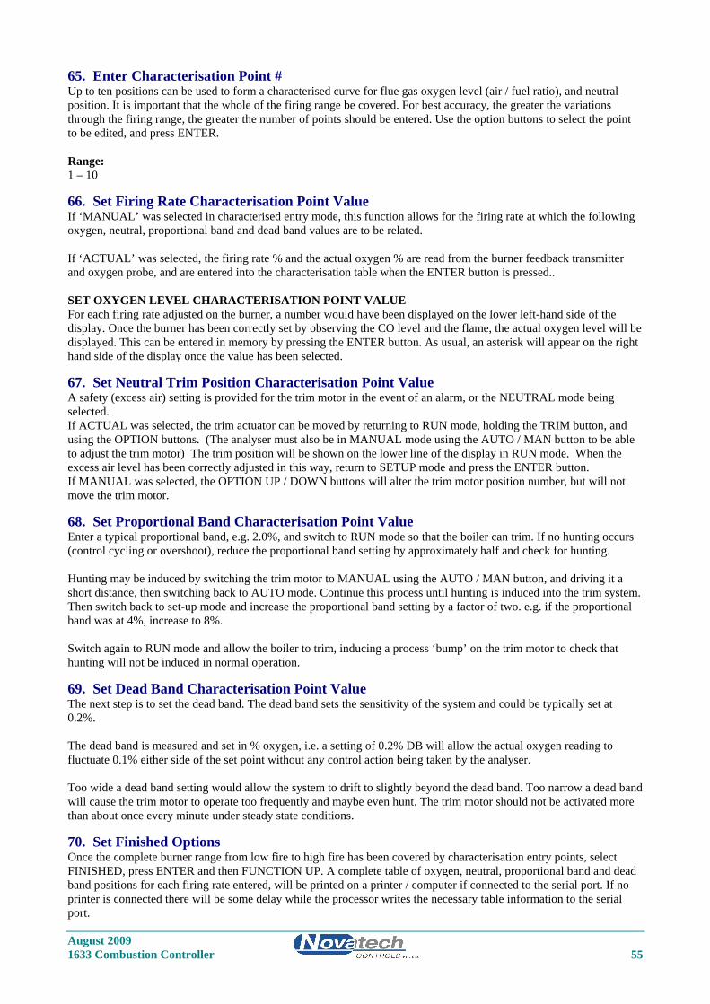
August 2009 1633 Combustion Controller 55
65. Enter Characterisation Point # Up to ten positions can be used to form a characterised curve for flue gas oxygen level (air / fuel ratio), and neutral position. It is important that the whole of the firing range be covered. For best accuracy, the greater the variations through the firing range, the greater the number of points should be entered. Use the option buttons to select the point to be edited, and press ENTER. Range: 1 – 10
66. Set Firing Rate Characterisation Point Value If ‘MANUAL’ was selected in characterised entry mode, this function allows for the firing rate at which the following oxygen, neutral, proportional band and dead band values are to be related. If ‘ACTUAL’ was selected, the firing rate % and the actual oxygen % are read from the burner feedback transmitter and oxygen probe, and are entered into the characterisation table when the ENTER button is pressed.. SET OXYGEN LEVEL CHARACTERISATION POINT VALUE For each firing rate adjusted on the burner, a number would have been displayed on the lower left-hand side of the display. Once the burner has been correctly set by observing the CO level and the flame, the actual oxygen level will be displayed. This can be entered in memory by pressing the ENTER button. As usual, an asterisk will appear on the right hand side of the display once the value has been selected.
67. Set Neutral Trim Position Characterisation Point Value A safety (excess air) setting is provided for the trim motor in the event of an alarm, or the NEUTRAL mode being selected. If ACTUAL was selected, the trim actuator can be moved by returning to RUN mode, holding the TRIM button, and using the OPTION buttons. (The analyser must also be in MANUAL mode using the AUTO / MAN button to be able to adjust the trim motor) The trim position will be shown on the lower line of the display in RUN mode. When the excess air level has been correctly adjusted in this way, return to SETUP mode and press the ENTER button. If MANUAL was selected, the OPTION UP / DOWN buttons will alter the trim motor position number, but will not move the trim motor.
68. Set Proportional Band Characterisation Point Value Enter a typical proportional band, e.g. 2.0%, and switch to RUN mode so that the boiler can trim. If no hunting occurs (control cycling or overshoot), reduce the proportional band setting by approximately half and check for hunting. Hunting may be induced by switching the trim motor to MANUAL using the AUTO / MAN button, and driving it a short distance, then switching back to AUTO mode. Continue this process until hunting is induced into the trim system. Then switch back to set-up mode and increase the proportional band setting by a factor of two. e.g. if the proportional band was at 4%, increase to 8%. Switch again to RUN mode and allow the boiler to trim, inducing a process ‘bump’ on the trim motor to check that hunting will not be induced in normal operation.
69. Set Dead Band Characterisation Point Value The next step is to set the dead band. The dead band sets the sensitivity of the system and could be typically set at 0.2%. The dead band is measured and set in % oxygen, i.e. a setting of 0.2% DB will allow the actual oxygen reading to fluctuate 0.1% either side of the set point without any control action being taken by the analyser. Too wide a dead band setting would allow the system to drift to slightly beyond the dead band. Too narrow a dead band will cause the trim motor to operate too frequently and maybe even hunt. The trim motor should not be activated more than about once every minute under steady state conditions.
70. Set Finished Options Once the complete burner range from low fire to high fire has been covered by characterisation entry points, select FINISHED, press ENTER and then FUNCTION UP. A complete table of oxygen, neutral, proportional band and dead band positions for each firing rate entered, will be printed on a printer / computer if connected to the serial port. If no printer is connected there will be some delay while the processor writes the necessary table information to the serial port.

August 2009 56 1633 Combustion Controller
71. Print Characterisation Table Printing the characterised table is in progress. Wait six seconds for completion, and the set-up menu will return to set-up step 72.
72. Damping Factor Each time a new reading is read from the oxygen probe, the new reading is averaged with the last readings taken, before the new average is either displayed on the LCD, or sent to the 4 to 20 mA output. The number of readings that are averaged together is adjustable with this function. A value of five for example, means that the new reading from the probe and the previous four readings are averaged together before being displayed. A value of one entered here will mean that every new reading from the probe will be sent to the display unaltered. The smoothing of the oxygen signal is an exponential function. If a factor of 5 is used, a step change of input signal will take about 8 seconds to reach 63% of the change on the output / display. Range 1 to 20. The default setting is 5.
73. Single or Dual Fuel Enter single or dual fuel (for the efficiency calculation). This step and steps 74 to 85 will be skipped if efficiency, oxygen deficiency combustibles %, or maximum CO2 is not selected in Set-up steps 25, 29 or 55 for display or output on the transmitter channels or the printer port. Options: 1. Single * 2. Dual
74. Fuel Number 1 ‘A’ Value ‘A’ is the heat of combustion of the fuel per gram atom of contained carbon. Enter the correct value of ‘A’ (Refer notes in Appendix 1).
75. Fuel Number 1 ‘H’ Value ‘H’ is the hydrogen / carbon atom ratio in the fuel. Enter the correct value of ‘H’ (Refer notes in Appendix 1).
76. Fuel Number 1 ‘O’ Value ‘O’ is the oxygen / carbon atom ratio in the fuel. Enter the correct value of ‘O’ (Refer notes in Appendix 1).
77. Fuel Number 1 ‘N’ Value ‘N’ is the nitrogen / carbon atom ratio in the fuel. Enter the correct value of ‘N’ (Refer notes in Appendix 1).
78. Fuel Number 1 ‘S’ Value ‘S’ is the sulphur / carbon atom ratio in the fuel. Enter the correct value of ‘S’ (Refer notes in Appendix 1).
79. Fuel Number 1 ‘M’ Value ‘M’ is the ratio of water molecules to carbon atoms in the fuel. Enter the correct value of ‘M’ (Refer notes in Appendix 1). For single fuel applications the next set-up step will be 86, for dual fuel the next step is 80
80. Fuel Number 2 ‘A’ Value ‘A’ is the heat of combustion of the fuel per gram atom of contained carbon. Enter the correct value of ‘A’ (Refer notes in Appendix 1).
81. Fuel Number 2 ‘H’ Value ‘H’ is the hydrogen / carbon atom ratio in the fuel. Enter the correct value of ‘H’ (Refer notes in Appendix 1).
82. Fuel Number 2 ‘O’ Value ‘O’ is the oxygen / carbon atom ratio in the fuel. Enter the correct value of ‘O’ (Refer notes in Appendix 1).

August 2009 1633 Combustion Controller 57
83. Fuel Number 2 ‘N’ Value ‘N’ is the nitrogen / carbon atom ratio in the fuel. Enter the correct value of ‘N’ (Refer notes in Appendix 1).
84. Fuel Number 2 ‘S’ Value ‘S’ is the sulphur / carbon atom ratio in the fuel. Enter the correct value of ‘S’ (Refer notes in Appendix 1).
85. Fuel Number 2 ‘M’ Value ‘M’ is the ratio of water molecules to carbon atoms in the fuel. Enter the correct value of ‘M’ (Refer notes in Appendix 1).
86. Reference Air Selection The reference air supply for the oxygen sensor or probe is normally supplied from the analyser. If the internal pump is not being used, ‘External’ must be selected to stop the ‘Ref Pump Fail’ alarm. If an external air supply that has a known relative humidity, select ‘Instrument Air’. This will allow the relative humidity level to be entered in set-up 87. Half a litre per minute provides sufficient reference air for any sensor. Note: If ‘Internal’ is selected, and a reference air flow sensor is connected to CN8 on the 1630-2 (terminal) PCB, the pump is cycled on and off within a minute. Options: Internal * External Instrument air
87. Reference Air Relative Humidity This selection will only appear if ‘Instrument Air’ is selected in set-up 86. If the reference air is being supplied from an instrument air supply, the relative humidity will be different from the ambient air being measured within the analyser. In this case set the set the RH to the RH of the air supply. As a guide, the RH of a compressor driven air supply is about 10%. Range: 1-100%
88. Modbus Address This function is used when networking of one or more analyser back to a master computer or data acquisition system is required. For more details on the functions of the MODBUS see Section 2.11, and Appendix 6. The valid range of MODBUS addresses is from 1 to 31. Any analyser with zero selected as the MODBUS address will have the MODBUS disabled, and the data log function enabled. For the connection details, see Section 3.15. NOTE: If the MODBUS address is changed, the analyser must be turned off and back on for the address change to take effect. Range: 0 – 31 The default setting is 0.

August 2009 58 1633 Combustion Controller

August 2009 1633 Combustion Controller 59
6 MAINTENANCE Section Number TRANSMITTER MAINTENANCE 6.1 COLD START ................................................................................................................................ 60 6.2 A/D CALIBRATION ...................................................................................................................... 60 6.3 D/A (4-20MA OUTPUT CHANNELS) CALIBRATION .............................................................. 61 6.4 PUMP REPLACEMENT ................................................................................................................ 61 6.5 BACK-UP BATTERY REPLACEMENT ...................................................................................... 61 6.6 ELECTRONIC REPAIRS ............................................................................................................... 61
PROBE MAINTENANCE 6.7 INSTALLING A NEW PROBE ..................................................................................................... 62 6.8 TEST EQUIPMENT REQUIRED .................................................................................................. 62 6.9 TESTING A PROBE ...................................................................................................................... 63 6.10 PROBE THERMOCOUPLE ........................................................................................................... 63 6.11 HEATER FAILURE ....................................................................................................................... 63 6.12 FILTER BLOCKAGE ..................................................................................................................... 63

August 2009 60 1633 Combustion Controller
TRANSMITTER MAINTENANCE
6.1 COLD START A ‘COLD START’ will reset all ‘Set-up’ mode entries to their factory default values. The characterisation table can also be reset to the factory default at the same time as the other set-up menu items if required. ‘COLD START’ will show on the display for a second prior to a microprocessor initialising sequence, which takes about seven seconds. After a ‘COLD START’, it is necessary to set all new variables in the ‘SET-UP’ mode, including calibration voltages and time and date. To initiate a ‘COLD START’ without resetting the characterisation tables- Turn the mains power off Remove the ‘COLD START LINK’ (this is located on the door PCB, next to the keyboard lock switch, behind the shield) Turn the mains power on. The message “Cold Start......” will be displayed. Leave the LINK off until the message “Replace c/s Link” is displayed. Replace the LINK. The date and version number of the software will be displayed. To initiate a ‘COLD START’ including resetting the characterisation tables- Turn the mains power off Remove the ‘COLD START LINK’ (this is located on the door PCB, next to the keyboard lock switch, behind the shield) Hold the ‘FUNCTION DOWN’ and the ‘AUTOCAL’ buttons. Turn the mains power on. The message “Cold Start......” will be displayed. Hold the buttons until the message “Cold Start......” is displayed. To confirm the resetting of the characterisation table “Init Char Table” will be displayed. Leave the LINK off until the message “Replace c/s Link” is displayed. Replace the LINK. The date and version number of the software will be displayed. A ‘WARM START’, which is performed by applying power with the COLD START LINK in its place, will retain all data previously entered in the Set-up mode including the characterisation table.
6.2 A/D CALIBRATION
Location of Calibration Test Points
Ribbon Cable
Ribbon Cable
Reference voltage
Reference voltagetest points.
common point.
Door Shield
RE
F V
OL
TS
1630-1 PCB
1
C
4
3
2
40 Way
16 Way
COLD-START linkis located under thedoor shield.

August 2009 1633 Combustion Controller 61
The analyser maintains its accuracy over a year by continuously checking itself against internal stabilised references. The only calibration required is to set the actual values of these references into battery backed memory. The analyser will read these references every minute and update its zero and span correction factors. See Section 5.5.7 to 10. These references should be checked every 12 months. An AUTOCAL of the analog output section should always be performed if these references are altered. See Section 6.3.
6.3 D/A (4-20MA OUTPUT CHANNELS) CALIBRATION The calibration can either be done using the ‘Auto Cal’ or ‘Manual Cal’. Auto Cal The ‘Auto Cal’ mode is selected in set-up 11 (and 14 for channel 2). The analyser will automatically divert the output back to the input, measure the offset and span, and record the calibration factors for each channel. If either of the channels are selected to be calibrated manually, an ‘Auto Cal’ will not change the factors. Manual Cal The ‘Manual Cal’ mode is selected in set-up 11 (and 14). Set the 4mA calibration first and then the 20mA calibration. 1. Select ‘Set 4mA Trim’ in set-up 11 (or 14). 2. Return to RUN mode. 3. Measure the output on the channel to be calibrated with a digital multimeter. If the current is not exactly 4.00mA,
return to set-up mode and change the 4mA calibration factor in set-up 12 (or 15). 4. Re-measure the current while back in RUN mode until the current is within 3.9 to 4.1mA. 5. Return to set-up mode and select ‘Manual Cal’ in set-up 11 (or 14). Set the 20mA calibration factor. 6. Select ‘Set 20mA Trim’ in set-up 11 (or 14). 7. Return to RUN mode. 8. Measure the output on the channel to be calibrated with a digital multimeter. If the current is not exactly 20.00mA,
return to set-up mode and change the 20mA calibration factor in set-up 13 (or 16). 9. Re-measure the current while back in RUN mode until the current is within 19.9 to 20.1mA. 10. Return to set-up mode and select ‘Manual Cal’ in set-up 11 (or 14). This calibration is now saved in battery backed memory until The factors are changed in the manual calibration The analyser is forced into a COLD-START (see section 6.1) The calibration mode in set-up 11 (or 14) is changed to Auto Cal and an Auto Cal is initiated. NOTE: The 4mA or the 20mA trim mode will only be held on the output channels for 30 minutes before automatically returning to ‘Manual Cal’ mode in set-up 11 (or 14).
6.4 PUMP REPLACEMENT The reference air pump is mounted on the 1630-2 PCB in the base of the analyser. The operation of the pump is monitored by the analyser and alarms will be shown if a fault occurs. (“Pump Fail” alarm, “Pump Blocked” alarm ) To replace the pump, unplug all the field wiring terminals. ie. Probe connectors, power connector etc. The nuts for the pump screws are captive into the PCB, enabling the pump to be removed WITHOUT removing the PCB. The pump wires can be unplugged.
6.5 BACK-UP BATTERY REPLACEMENT The back-up battery is contained within the battery-like real time clock / memory module, plugged into socket M2. It is rated for an average service life of greater than ten years. The module is not re-chargeable and should be replaced every three years in a stored transmitter with power off or every eight years with transmitters that have had the power on. The memory module must be purchased from Novatech Controls or an agent of Novatech Controls. After replacing the battery, re-enter all set-up mode functions.
6.6 ELECTRONIC REPAIRS Electronic schematics are included in Appendix 5. A competent electronic technician could perform troubleshooting with these schematics, aided by the analyser self-diagnostic alarms. It is recommended that service be performed on a changeover circuit board basis. A fast turn-around or replacement service is available from Novatech or accredited service agents. Other service aids, including a test EPROM firmware package and probe input simulator are also available.

August 2009 62 1633 Combustion Controller
PROBE MAINTENTANCE
6.7 INSTALLING A NEW PROBE Whenever a new oxygen probe is installed, the millivolt offset value should be entered. To achieve this, refer to set-up 10. The probe offset is noted on a tag or label attached to probe. To check an offset on site, the probe must be sensing air with reference air connected and allowed to settle at the operating temperature for 30 minutes. Read the offset in ‘RUN’ mode in millivolts on the lower line. Offset errors can occur if the probe does not have some air passing over it. A gentle flow of air in the calibration check port can be provided by a reference air pump or similar. If a probe is in a process with the process running, the air purge on the sensing side of the oxygen sensor will only be successful if the probe has a filter or small sensing hole. Probes with open sensing ends or with large sensing holes allow the process gas to mix with the calibration gas, giving a false reading. For heated probes, if the combustion appliance is not operational and the probe heater is interlocked with the ‘FUEL ON’ signal, the ‘BURNER BYPASS’ switch should be set to ‘BYPASS’ to power the probe heater after removing the probe from the flue. For unheated probes, the sensing tip must be raised to at least 650°C (1200°F) with a portable furnace.
CAUTION DANGER
Return the ‘BURNER BYPASS’ switch to normal (off) before installing the probe in the flue.
6.8 TEST EQUIPMENT REQUIRED All measurements are simplified if an analyser is connected to the probe. Readings can then be easily taken of probe impedance, EMF, temperature and percent oxygen. The analyser also provides proper heater control for heated probes. The following tests are described using readily available workshop equipment where an analyser is not available. If an analyser is available the same test procedures will apply. First check all alarms on the analyser, allowing time for the probe to heat up after switch on. An instrument to measure probe EMF and temperature is required. A 3 1/2 or 4 1/2 digit multimeter will perform both measurements. A separate temperature indicator to suit the probe thermocouple type is also useful, although not necessary. A reference air pump is required and a cylinder of calibration check gas e.g. 2 % oxygen in nitrogen. The cylinder should have a pressure and flow regulator. Both of these are inexpensive devices available from gas supply companies. The calibration check gas should be chromatograph tested to an accuracy of 0.1 % oxygen.
TEST EQUIPMENT FOR UNHEATED PROBES A small test furnace capable of raising the probe tip temperature to over 700°C (1300°F) is required. The furnace should have a uniform temperature for about 50 mm (2”) either side of the sensor tip.
TEST EQUIPMENT FOR HEATED PROBES If a 1633 analyser is available at the test location then no other equipment will be required. If not, then a controllable power source for the heater is required. A Variac (variable transformer), set to approximately 60 volts will regulate the probe temperature to over 700°C (1300°F).

August 2009 1633 Combustion Controller 63
6.9 TESTING A PROBE With the probe heated to over 700°C (1300°F), either from a small test furnace or its own internal heater, connect a digital multimeter to the probe electrode conductors. Connect the multimeter positive to the internal electrode conductor. Connect reference air to and apply a gentle purge of air to the probe calibration check port. Reference airflow should be 50 to 500 cc / minute (6 to 60 scfm). The multimeter should read zero millivolts ± two millivolts. If not, then there is a problem with the probe electrodes and the sensor needs refurbishing. Normally a faulty probe electrode is indicated with a high source impedance. 1234 sensors do not require reference air but a gentle flow of air should be admitted into the sample connection. To test the source impedance, set the multimeter to read ohms and take a measurement, within a couple of seconds, of the probe impendence. Reverse the multimeter and repeat the reading. Take the average of the two readings for an approximate measurement of impedance. If the impedance is above 10kΩ, then the probe needs to be replaced. The probe must be over 700°C (1300°F) or above for this measurement. The reason that impedance measurements need to be performed quickly, is that the zirconia sensor polarises with the DC voltage from the multimeter across it. If the probe tests reveal less than 2 mV offset and a good impedance reading, the next step is to apply a calibration check gas. The calibration check gas should be inserted in the calibration check port. With the calibration check gas flowing, the probe should develop an EMF according to the tables in Appendix 2. If the EMF reading is low then there may be insufficient calibration check gas flow. Increase the calibration check gas until the reading is correct. An excessive calibration check gas flow will cause cooling on one surface of the sensor, giving temperature differential errors on the sensor. As an alternative, using the reference air port, the calibration check gas can be inserted into the inside of a probe sensor. This requires a lower flow rate, and thus lower usage of calibration check gas. The flow rate should be similar to that of the reference air, which should be removed for internal calibration check. The probe EMF reading will be identical but negative in polarity. A small flow of air should be flowing over the outside of the sensor, when testing in this way. Occasionally, a probe can develop an offset with a polluted electrode caused by contaminants in the flue gas stream. In this case the impedance may be OK but the output incorrect. This phenomenon is rare.
6.10 PROBE THERMOCOUPLE Although some unheated probes are specified without a thermocouple, most probes, both heated and unheated, have an integral thermocouple which is fitted in to the four bore insulator. The analyser has an alarm function that will advise the operator of an open circuit thermocouple, however bench testing can be performed by simply measuring the thermocouple continuity.
6.11 HEATER FAILURE For heated probes, a heater failure will cause a ‘PROBE UNDER TEMP’ or ‘HEATER FAIL’ alarm. Heaters can be tested with a continuity test. The heater impedance should be approximately 100Ω. Should the heater be open or short-circuited, replace the probe.
6.12 FILTER BLOCKAGE For oxygen probes with filters in installations with entrained solids in the flue gas, it is sometimes necessary to replace the filter. Filters are normally cleared with back purging. However fine fly ash or other particles can ultimately completely block a filter necessitating filter replacement. The filters can be replaced with new ones.

August 2009 64 1633 Combustion Controller
APPENDIX 1
CONSTITUENT VALUES FOR FUELS If the transmitter is set up to have readout or output of combustibles or maximum carbon dioxide, then the fuel constituents must be entered. Any or all of the variables can be modified and entered in set-up steps 39 to 45 and 46 to 51. (Refer to Section 5.5). Your fuel supplier or chemist should be able to give you all these values. A is the heat of combustion of the fuel per gram atom of contained carbon.
H is the H/C atom ratio in the fuel.
O is the O/C atom ratio in the fuel.
N is the N/C atom ratio in the fuel.
S is the S/C atom ratio in the fuel.
M is the ratio of H2O molecules to C atoms in the fuel
FUEL A H O N S M
Blast Furnace Gas 50.55 0.08 1.3 3.08 b a
Coke Oven Gas 256.88 5.6 0.25 0.23 b a
Producer Gas 101.98 1.18 1.02 2.9 b a
Natural Gas 209.9 3.86 0 0.1 0 0
Propane, Natural 176.4 2.69 0 0 0 0
Butane, Refinery 166.1 2.34 0 0 0 0
Methanol 172.59 3.97 1 - - -
Gasoline, Motor 157.58 2.01 0 0 0 0
No 1 Distillate Oil 149.65 1.83 0 - 0 -
No 2 Distillate Oil 145.18 1.71 - - 0 -
No 4 Fuel Oil 145.54 1.6 - - 0.01 0
No 5 Residual Oil 142.25 1.44 - 0 0 0
No 6 Residual Oil 136.52 1.25 0.01 0 0 0
Wood, Non-Resinous 110.91 2.26 1.07 0 0 c
Coal, Bituminous 116.88 0.74 0.05 0 0 0.03
Coal, Anthracite 104.98 0.35 0.05 0 0.01 0.04
Coke 99.63 0.11 0.01 0.01 0 0.01 a. The moisture level varies depending on the process details. The calculated values assume M = O. b. The sulphur level varies depending on the process details. The calculated values assume S = O. c. Variable.
Values calculated from the North American Combustion Handbook, Tables 2.1a and 2.1b.

August 2009 1633 Combustion Controller 65
APPENDIX 2
PROBE OR SENSOR EMF TABLES
ZIRCONIA OXYGEN SENSOR OUTPUT (mV) PROBE TYPE 1231, SENSOR TYPE 1234
OXYGEN Probe EMF OXYGEN Probe EMF% @ 720°C (1320°F) % @ 720°C (1320°F)
20.95 0 10.0 15.93020.5 0.517 9.5 17.03320.0 1.046 9.0 18.19619.5 1.589 8.5 19.42619.0 2.147 8.0 20.73018.5 2.719 7.5 22.12018.0 3.306 7.0 23.60717.5 3.911 6.5 25.20417.0 4.533 6.0 26.93016.5 5.173 5.5 28.80816.0 5.834 5.0 30.86715.5 6.515 4.5 33.14515.0 7.219 4.0 35.69514.5 7.947 3.5 38.59014.0 8.700 3.0 41.94013.5 9.481 2.5 45.91313.0 10.292 2.0 50.79712.5 11.134 1.5 57.13512.0 12.011 0.9 66.18211.5 12.925 0.4 82.16811.0 13.881 0.2 99.51810.5 14.881 0.1 114.347
'K' Type TC 29.965 mV @ 720°C (1320°F) These tables are based on the Nernst equation:
421.4695.20
log 2
−
⎟⎠⎞
⎜⎝⎛
=
OTEMF
e
Where T is temperature° K

August 2009 66 1633 Combustion Controller
ZIRCONIA OXYGEN PROBE OUTPUT (mV) PROBE TYPE 1232
OXYGEN 600 700 800 900 1000 1100 1200 1300 1400% (1110) (1290) (1470) (1650) (1830) (2010) (2190) (2370) (2550)20 0.873 0.973 1.073 1.173 1.273 1.373 1.473 1.573 1.67319.5 1.349 1.504 1.658 1.813 1.967 2.122 2.276 2.431 2.58519 1.838 2.048 2.259 2.469 2.680 2.890 3.100 3.311 3.52118.5 2.339 2.607 2.875 3.143 3.411 3.679 3.947 4.215 4.48318 2.855 3.182 3.509 3.835 4.162 4.489 4.816 5.143 5.47017.5 3.385 3.772 4.160 4.547 4.935 5.323 5.710 6.098 6.48517 3.930 4.380 4.830 5.280 5.730 6.180 6.630 7.080 7.53016.5 4.491 5.006 5.520 6.034 6.549 7.063 7.578 8.092 8.60616 5.070 5.651 6.231 6.812 7.393 7.973 8.554 9.135 9.71515.5 5.667 6.316 6.965 7.614 8.263 8.913 9.562 10.211 10.86015 6.284 7.004 7.723 8.443 9.163 9.882 10.602 11.322 12.04214.5 6.922 7.714 8.507 9.300 10.093 10.885 11.678 12.471 13.26314 7.582 8.450 9.318 10.187 11.055 11.923 12.792 13.660 14.52813.5 8.266 9.212 10.159 11.106 12.052 12.999 13.946 14.892 15.83913 8.976 10.004 11.032 12.060 13.087 14.115 15.143 16.171 17.19912.5 9.713 10.826 11.938 13.051 14.163 15.276 16.388 17.500 18.61312 10.481 11.682 12.882 14.082 15.283 16.483 17.684 18.884 20.08411.5 11.282 12.574 13.866 15.158 16.450 17.742 19.034 20.326 21.61811 12.118 13.506 14.893 16.281 17.669 19.057 20.445 21.833 23.22010.5 12.993 14.481 15.969 17.457 18.945 20.433 21.921 23.409 24.89710 13.911 15.504 17.097 18.690 20.283 21.876 23.469 25.063 26.6569.5 14.875 16.579 18.283 19.986 21.690 23.394 25.097 26.801 28.5049 15.892 17.712 19.533 21.353 23.173 24.993 26.813 28.633 30.4538.5 16.967 18.911 20.854 22.797 24.740 26.684 28.627 30.570 32.5138 18.108 20.182 22.255 24.329 26.403 28.477 30.551 32.625 34.6987.5 19.322 21.535 23.747 25.960 28.173 30.386 32.599 34.812 37.0257 20.619 22.981 25.342 27.704 30.065 32.427 34.788 37.150 39.5116.5 22.013 24.534 27.056 29.577 32.098 34.619 37.140 39.661 42.1826 23.519 26.212 28.906 31.600 34.293 36.987 39.680 42.374 45.0675.5 25.155 28.036 30.917 33.798 36.679 39.560 42.442 45.323 48.2045 26.948 30.035 33.121 36.207 39.293 42.380 45.466 48.552 51.6394.5 28.930 32.243 35.557 38.870 42.183 45.496 48.810 52.123 55.4364 31.145 34.712 38.279 41.846 45.413 48.980 52.547 56.115 59.6823.5 33.657 37.512 41.366 45.221 49.076 52.930 56.785 60.640 64.4943 36.557 40.743 44.930 49.117 53.303 57.490 61.677 65.864 70.0502.5 39.986 44.565 49.145 53.724 58.304 62.883 67.463 72.042 76.6222 44.183 49.243 54.303 59.364 64.424 69.484 74.544 79.604 84.6651.5 49.594 55.274 60.954 66.634 72.314 77.994 83.674 89.354 95.0341 57.221 63.774 70.327 76.881 83.434 89.988 96.541 103.094 109.6480.5 70.258 78.305 86.351 94.398 102.445 110.491 118.538 126.584 134.6310.2 87.493 97.514 107.534 117.554 127.575 137.595 147.616 157.636 167.657
Thermocouple mV'K' Type 24.905 29.129 33.275 37.326 41.276 45.119 48.838 52.410 -'J' Type 33.102 39.132 45.494 51.877 57.953 63.792 69.553 - -'R' Type 5.583 6.743 7.950 9.205 10.506 11.850 13.228 14.629 16.040'S' Type 5.239 6.275 7.345 8.449 9.587 10.757 11.951 13.159 14.373'N' Type 20.613 24.527 28.455 32.371 36.256 40.087 43.846 47.513 -
TEMPERATURE ºC (°F)
These tables are based on the Nernst equation:
421.4695.20
log 2
−
⎟⎠⎞
⎜⎝⎛
=
OTEMF
e
Where T is temperature° K
Thermocouple information from NIST ITS-90 data tables

August 2009 1633 Combustion Controller 67
APPENDIX 3
% OXYGEN SCALE TO LOGARITHMIC
OXYGEN FULL SCALE% %0.1 00.15 7.650.2 13.10.3 20.70.4 26.20.6 33.80.8 39.21 43.51.5 51.12 56.53 64.24 69.66 77.38 82.710 86.912 90.414 93.316 95.818 9820 100

August 2009 68 1633 Combustion Controller
APPENDIX 4
SAMPLE LOG PRINT OUT
Novatech Controls 29-08-2000 12:52:28 Oxygen % 5.2% Runtime 1325:49 Fire 83% SP 5.1 % Trim= 90% Emf mV 29.9 Probe Temp 723 C Aux Deg 219 C Probe Imp 0.0K Efficiency 88.0% Combstbles 0.00 % Next Print at 12:57:28 29-08-2000 07:49:29 29-08-2000 RefPump Fail Accepted

August 2009 1633 Combustion Controller 69
APPENDIX 5
CIRCUIT SCHEMATICS

August 2009 70 1633 Combustion Controller
11
22
33
44
55
66
77
88
DD
CC
BB
AA
Title
Num
ber
Revi
sion
Size A3
Dat
e:22
/04/
2008
Shee
t o
fFi
le:
C:\D
ocum
ents
and
Set
tings
\..\1
63x-
1.pr
jD
raw
n By
:
Nov
atec
h Co
ntro
ls
1630
-1Bl
ock
Dia
gram
1.6
14 FH
C
163x
Ana
lyse
r
P5-[
0..7
]
L4-[
3..6
]
DA
C-PS
-[0.
.5]
P6-[
0..7
]
P4-[
0..7
]
D-A
2
P3-2
/P6-
1
Ser-[
1..5
]
SVcc
P3-0
Vcc
Gnd 01
Erro
r
SVee
AD
CA
DC.
SCH
DA
C-PS
-[0.
.5]
P6-[
0..7
]
P3-[
0..7
]
/P6-
1
Ser-[
1..5
]
SVcc
SVee
Vcc
Gnd
DA
CSD
ACS
.SCH
L4-[
3..6
]
D-A
2
P3-[
0..7
]
P4-[
0..7
]
P6-[
0..7
]
P5-[
0..7
]
P3-2
P3-0
Vcc
Gnd
Erro
r
MIC
ROM
ICRO
.SCH
L4-[
3..6
]
P4-[
0..7
]
P5-[
0..7
]
P6-[
0..7
]
DA
C-PS
-[0.
.5]
P3-[
0..7
]
Ser-[1..5]
SVcc
Vcc
P3-0
D-A
2
P3-2
/P6-
1
Gnd
Erro
r
Svee

August 2009 1633 Combustion Controller 71
11
22
33
44
55
66
77
88
DD
CC
BB
AA
Title
Num
ber
Revi
sion
Size A3
Dat
e:22
/04/
2008
Shee
t o
fFi
le:
C:\D
ocum
ents
and
Set
tings
\..\A
dc.sc
hD
raw
n By
:
R5410
k
R5310
k
R52
10k
R56
10k
R51
1k
R70
1k8
R681
2K R63
82K
5 1%
R69
270k
R71
1k
R67
1k5
AV
cc
Gnd
C18
0.01
uF
C19
0.01
uFA
Vee
Gnd
C15
0.01
uF
X0
13
X1
14
X2
15
X3
12
X4
1
X5
5
X6
2
X7
4
INH
6
A11
B10
C9
VEE
7
X3
VCC
16
GN
D8
IC32
CD40
51 S
MD
X0
13
X1
14
X2
15
X3
12
X4
1
X5
5
X6
2
X7
4
INH
6
A11
B10
C9
VEE
7
X3
VCC
16
GN
D8
IC30
CD40
51 S
MD
Gnd
Gnd
Gnd
X0
13
X1
14
X2
15
X3
12
X4
1
X5
5
X6
2
X7
4
INH
6
A11
B10
C9
VEE
7
X3
VCC
16
GN
D8
IC28
CD40
51 S
MD
X0
13
X1
14
X2
15
X3
12
X4
1
X5
5
X6
2
X7
4
INH
6
A11
B10
C9
VEE
7
X3
VCC
16
GN
D8
IC31
CD40
51 S
MD
X0
13
X1
14
X2
15
X3
12
X4
1
X5
5
X6
2
X7
4
INH
6
A11
B10
C9
VEE
7
X3
VCC
16
GN
D8
IC29
CD40
51 S
MD
AV
ee(5
)
AV
ee(5
)
AV
ee(5
)
AV
ee(5
)
AV
cc(5
)
AV
cc(5
)
AV
cc(5
)
AV
cc(5
)
89
IC18
D
74H
C04
P5-[
0..7
]
014
15
26
12
3
11
1
13
4
10
2
Vcc
16
Gnd
83
15
Vee
90
12
3
/En
7
IC22
74H
C431
6 SM
D
R104
100k
R103
100k
R102
1k
R101
1k
R100
1k
R99
1kR9
710
0k
R98
100k
R96
1k
R95
1kR9
31k
R91
1kR8
91k
C33
1.0/
16V
Tant
C32 0.1
C31 0.1
C30
1.0/
16V
Tan
t
C29 0.1
C28 0.1
C27 0.1
C26 0.1
R94
1kR9
21k
R90
1k
Gnd
R113
250R 1%
R111
1k5 1%
R110
9k1 1%
R108
4k7 1%
R106
6k8 1%
R105
2k2
Gnd
AV
cc(5
)
R60
6k8
R57
1k
R61
1kR5
810
k
AV
cc(5
)
AV
ee(5
)
Gnd
L4-[
3..6
]
Gnd
Gnd
AV
cc
R88
1k
R86
1kR8
51k
R84
1kR8
31k
R82
1kR8
01k
R78
1k
R87
1k
R77
1kR7
91k
R81
1k
C25 0.1
C22 0.1
C21 0.1
C20 0.1 Gnd
Gnd
C24 0.1
Probe analog inputs
R45
100k
R42
10k
Gnd
C10
10/1
6V T
ant
Gnd
Gnd
Gnd
Gnd
AV
cc(5
)
AV
ee(5
)
Gnd
Gnd
AV
ee(5
)
R59
1k
R66
12k
R65
47k
C16
270p
npo
Gnd
AV
cc
AV
ee
Gnd
3 21
4 11
IC26
AO
PA42
34U
A
5 67
IC26
BO
PA42
34U
A
10 98
IC26
CO
PA42
34U
A
12 1314
IC26
DO
PA42
34U
A
O2
sens
or #
1+
Prob
e TC
+
Aux
TC
/ Sen
TC
#2 -
CO2
i/p(1
637)
-
Rear
hea
d / R
GC
TC -
Burn
er f/
b po
tTr
im f/
b po
t
Hea
ter i
nter
lock
+12v
ana
log
pow
er
P5-4
P5-3
P5-2
P5-5
P5-4
P5-3
P5-2
P5-4
P5-3
P5-2
P5-4
P5-3
P5-2
DC
volts
pre
-regu
lato
r50
/60
mai
ns fr
eq
Hea
ter d
rive
enab
le
/P6(
1) C
lock
+5 D
igita
l pow
er
Rear
hea
d / R
GC
TC +
Ana
log
grou
nd
CJ A
mbi
ent s
enso
r
R76
100k
AV
ee(5
)
Cal 4
-20m
A si
gnal
Chan
nel #
1 +p
/sCh
anne
l #1
signa
lCh
anne
l #1
com
Chan
nel #
2 sig
nal
Chan
nel #
2 +p
/s
Chan
nel #
2 co
m
-12v
Ana
log
pow
er
Ref a
ir pu
mp
driv
e (D
A-1
)
+12v
Ana
log
pow
er
Ref a
ir pu
mp
curre
nt
P4-7
P4-1
R12
250R
Gnd
P4-3
12
714
IC34
A74
HC1
4 SM
D3
4
IC34
B
74H
C14
SMD
014 15 26
12 3 11 1
13 4 10 2
Vcc 16
Gnd 8
315
Vee 90 1 2 3
/En 7
IC27
74H
C431
6 SM
D
R75
10k
R74
2k2
R73
220k
R5510
k
R62
10k
R50
10k
C23
0.1
C11
1uF
non
pola
r
C12
10/1
6V T
ant
R41
RH se
nsor
3 21
8 4
IC24
A OPA
2132 56
7
IC24
B OPA
2132
Vcc
AV
ee(5
)
Gnd
Gnd
Gnd
AV
ee(5
)V
cc
Gnd
Gnd
P5-0
P5-1
L4-3
L4-4
L4-5
L4-6
P4-2
DA
C-PS
-[0.
.5]
P6(4
) Dig
o/p
dat
a
P6(5
) Dig
o/p
latc
hA
nalo
g Co
mP6
(6) D
ig i/
p da
ta
P6(7
) Dig
i/p
load
/shift
Dig
ital C
om
/P6-
1
P6-4
P6-5
P6-6
P6-7
P4-0
Gnd
Gnd
Vcc
AV
ccAV
ee
Nov
atec
h Co
ntro
ls
1630
-1In
put M
UX
's, A
DC
and
RH se
nsor
1.6
24 FH
C
163x
Ana
lyse
r
L4-[3..6]
P6-[
0..7
]
P4-[
0..7
]
D-A
2
/P6-
1
P6-[
0..7
]
DA
C-PS
-[0.
.5]
DA
C-PS
-0D
AC-
PS-1
DA
C-PS
-2D
AC-
PS-3
DA
C-PS
-4
DA
C-PS
-5
P3-2
P4-[
0..7
]
P5-[0..7]
R107
1k
Gnd
C34
10/1
6V T
ant
1 2 3 4 5 6 7 8 9 10 11 12 13 14 15 16 17 18 19 20 21 22 23 24 25 26 27 28 29 30 31 32 33 34 35 36 37 38 39 40
CN4
40 P
IN b
ox h
eade
r
RS-4
85 +
(Ser
4)RS
-485
- (S
er3)
RS-2
32 T
x (S
er2)
RS-2
32 R
x (S
er1)
Seria
l com
mon
(Ser
5)W
atch
dog
rela
y dr
ive
CO2
i/p (1
637)
+
Ser-
[1..5
]
Ser-1
Ser-2
Ser-4
Ser-3
Ser-5
P4-6
Erro
r
Ext R
ef A
ir Fl
ow S
ens
Ser-
[1..5
]
1213
IC34
F74
HC1
4 SM
D
Vcc
R64
100k
2.5v
SVcc
SVee
SVcc
SVee
I
C
O
IC36
78L0
5
I
C
O IC35
79L0
5
C38
0.1
C37
0.1
C39
1.0/
16V
Tan
t
Gnd
R72
12K
Gnd
+ i/p
14
Vo13
Comp i/p10
Vcc12
- i/p
1
Fout
7
Com
11
Cap 5
Vee 4
IC23
VFC
-32
Gnd
C14
.001
uF
+12v
Ser
ial c
oms p
ower
-12v
Ser
ial c
oms p
ower
O2
sens
or #
1-
Prob
e TC
-A
ux T
C / S
en T
C #2
+
C13
0.1 G
nd
C35
0.1
Gnd
P3-0
Avc
c(5)
Ave
e(5)
AV
cc
AV
ee
GndVcc
GndVcc
56
IC34
C74
HC1
4
Gnd
1 2 3 4 5 6 7 8 9 10 11 12 13 14 15 16
CN5
16PI
N
O2
sens
or #
2+O
2 se
nsor
#2-
CO2
signa
l + (1
637)
CO2
signa
l - (1
637)
Seria
l lat
ch o
/p e
nabl
e
C40 0.1
Erro
r
C41 0.1
C42 0.1
C43 0.1
C44 0.1
C45 0.1
C46 0.1
C47 0.1
C48 0.1
Gnd
Gnd
Gnd
C49
0.1
R115
1k
R116
1k C50
0.1
C51 0.1
Gnd G
nd
C52
0.1
C53
0.1
Gnd
Gnd
C54
0.1
Gnd
C55 0.1G
nd
C56 0.1
C57
0.1
Gnd
C58
0.1
Gnd
C60
0.01
uF
Gnd
C59 0.1
GndVcc
R117
1k2
R118
4k7
Gnd
48
IC33
LM33
6M-2
.5

August 2009 72 1633 Combustion Controller
11
22
33
44
55
66
77
88
DD
CC
BB
AA
Title
Num
ber
Revi
sion
Size A3
Dat
e:22
/04/
2008
Shee
t o
fFi
le:
C:\D
ocum
ents
and
Set
tings
\..\1
63x-
2.pr
jD
raw
n By
:
Nov
atec
h Co
ntro
ls
1630
-2Te
rmin
al a
lloca
tion,
Blo
ck d
iagr
am1.
5
14 FH
C
163x
Ana
lyse
r
Prob
e +
Prob
e -
Prob
e TC
+Pr
obe
TC-
TC2
/ Aux
+TC
2 / A
ux -
Out
put #
1+
Out
put #
2 +
Out
put #
2 -
Out
put #
1 -
Purg
e flo
w sw
Purg
e flo
w sw
Fuel
1/2
Com
ala
rmCo
m a
larm
Ala
rm re
lay
#2A
larm
rela
y #2
Purg
e so
leno
idPu
rge
sole
noid
Cal 1
sole
noid
Cal 2
sole
noid
Prob
e he
ater
#1
Prob
e he
ater
#1
Mai
ns A
ctiv
eM
ains
Neu
tral
Mai
ns E
arth
Fuel
1/2
Cal 1
sole
noid
Cal 2
sole
noid
Burn
er o
n i/p
Burn
er o
n i/p
+12v
supp
ly o
ut
RGC
I/P +
RGC
I/P -
Sens
or #
2 +
Sens
or #
2 -
Rem
ote
alar
m re
set
Rem
ote
alar
m re
set
RS-2
32 R
xRS
-232
Tx
Net
wor
k -
Net
wor
k +
Seria
l por
t com
mon
Ala
rm re
lay
#3A
larm
rela
y #3
Ala
rm re
lay
#4A
larm
rela
y #4
T+
-
IC1
LM35
TR4
BC55
0 TR3
BC55
0
D3
1N40
04V
cc
1 2 3 4 5 6 7 8 9 10 11 12 13 14 15 16 17 18 19 20 21 22 23 24 25 26 27 28 29 30 31 32 33 34 35 36 37 38 39 40
CN1
40 p
in ID
C cr
imp/
sold
erR3
1
10k
R38
10k
R15 1
0k
R710
k
R510
kR610
k
R14 10
kR1
3 10k
Vcc
L5-[
0..5
]
L6-[
0..7
]
L2-[
0..3
]
P6-[
0..7
]
/P6-
1
Sena
ble-
1
DIG
ITA
L LA
TCH
ESD
IGIO
.SCH
Out
putC
h#1+
Out
putC
h#1-
Out
putC
h#2+
Out
putC
h#2-
4-20
CalS
ig+
Ch#1
Sig
Ch#2
Sig
L5-[
0..5
]
SerP
S[1.
.3]
4-20
CalS
ig-
4-20
mA
DRI
VER
S4-
20D
RV.S
CH
4-20
CalS
ig+
PreR
eg
50/6
0Hz
P6-7
P6-6
P6-4
/P6-
1
P6-5
P4-6
Vcc
AG
nd
AV
cc
AV
ee
D1V
cc
D1G
nd
D2V
cc
D2G
nd
50/6
0Hz
HV
[1..6
]
Sol[1
..4]
L2-[
0..7
]
HtrE
n
L6-[
0..7
]
DA
-2
P4-5
PreR
eg
SerP
S[1.
.3]
Unr
eg
Erro
r
POW
ER S
UPP
LYPO
WER
.SCH
L2-1
L2-6
L2-2
L2-[
0..7
]
L5-[
0..5
]
Sol1
Sol2
Sol3
HV
4H
V5
HV
1H
V2
Ref A
ir Fl
ow S
enso
r
L2-4
P6-[
0..7
]
L6-[
0..7
]
Sol[1
..4]
HV
[1..6
]
1 2 3 4 5 6 7
CN7 1 2 3 4 5 6 7 8 9 10 11 12CN6 1 2 3 4 5
CN5 1 2 3 4
CN4 1 2 3 4 5 6 7 8
CN3 123456
CN11 12
CN10 1 2 3 4
CN12
TH1
135-
102D
AG
-J01
RL2
FBR-
46D
005P
RL6
RL1
RL5
Out
putC
h#1+
Out
putC
h#1-
Out
putC
h#2+
Out
putC
h#2-
L5-0
L5-1
L5-2
L5-3
HtrE
n
DA
-2
PreR
eg
P4-5
50/6
0Hz
Ch#1
Sig
Ch#2
Sig
R31M
R10
1M
R11
1M
12CN
8CO
N-P
H3.
8-2
3738A
Vcc
Sens
or #
2A
Vee
1 2 3 4 5 6 7 8 9 10 11 12 13 14 15 16 17 18 19 20 21 22 23 24 25 26 27 28 29 30 31 32 33 34 35 36 41 42 43 44 45 46 50 49 4751 52
Sol4
SerP
S[1.
.3]
SerP
S1
SerPS2
SerP
S3SV
cc
SVee
D1
R110
k
AG
nd
R12
10M
4-20
CalS
ig-
R910
M
1 2 3 4 5 6 7 8 9 10 11 12 13 14 15 16
CN2
16 P
IN ID
C cr
imp/
sold
er
1 2 3 4 5 6 7 8 9 10
CN14
Unr
eg +
12v
+5v
Dig
com
Dig
com
Sign
al +
Sign
al -
Ana
log
com
Ana
log
com
+12v
-12v
Unr
eg
Sena
ble-
1
Prob
e he
ater
#2
Prob
e he
ater
#2
12
CN15
53 54H
V6
C29
0.02
2uF/
240V
C30
0.02
2uF/
240V
Erro
r
TR?
BC55
0
TR?
BC55
0
TR?
BC55
0
D?
1N40
04
D?
1N40
04
D?
1N40
04
R?10
k
R?10
k
R?10
k
Vcc
Vcc
Vcc
1 2 3
CN?
12v
Sign
alCo
mm
onBu
rner
Fee
dbac
k Tr
ansd
ucer

August 2009 1633 Combustion Controller 73
11
22
33
44
55
66
77
88
DD
CC
BB
AA
Title
Num
ber
Revi
sion
Size A3
Dat
e:22
/04/
2008
Shee
t o
fFi
le:
C:\D
ocum
ents
and
Set
tings
\..\4
-20d
rv.sc
hD
raw
n By
:
Nov
atec
h Co
ntro
ls
1630
-24-
20m
A O
utpu
t Driv
ers
1.5
34 FH
C
163x
Ana
lyse
r
R19
100R
5 67
IC6B
LM35
8
R23
220K
R20
220K
R26
220K
R39
220K LE
D2
3mm
LED R1
7
100R
5 67
IC5B
LM35
8
R22
220K
R18
220K
R25
220K
R32
1M
LED
1 3mm
LED
3 21
8 4
IC6A
LM35
8
3 21
8 4
IC5A
LM35
8
Ch#1
+12
Ch#1
-12
Ch#1
sig
Ch#1
com
D1V
cc
D1G
nd
D1V
ee
Ch#2
+12
Ch#2
Com
Ch#2
-12
Ch#2
sig
D2V
ee
D2V
cc
D2G
nd
Out
putC
h#1+
Out
putC
h#1-
Out
putC
h#2+
Out
putC
h#2-
4-20
CalS
ig+
Ch#1
Sig
Ch#2
Sig
L5-4
L5-5
L5-[
0..7
]
RL4
FBR-
46D
005P
RL3
FBR-
46D
005P
TR2
BD13
9
TR1
BD13
9L5
-[0.
.7]4-
20Ca
lSig
+
Out
putC
h#1+
Out
putC
h#1-
Out
putC
h#2+
Out
putC
h#2-
Ch#2
Sig
Ch#1
Sig
R34
1M
R33
220K
D1G
nd
D2G
nd
R4 47R
C7 0.1u
F
C60.1u
F
4-20
CalS
ig-
4-20
CalS
ig-

August 2009 74 1633 Combustion Controller
11
22
33
44
55
66
77
88
DD
CC
BB
AA
Title
Num
ber
Revi
sion
Size A3
Dat
e:22
/04/
2008
Shee
t o
fFi
le:
C:\D
ocum
ents
and
Set
tings
\..\D
acs.s
chD
raw
n By
:
REFi
n6
Agnd 5
Vou
t7
Vdd8
Din
1
CLK
2
/CS
3
Dou
t4
IC1
MA
X53
8
R2 4K7
48
IC2
LM33
6M-2
.5
R111
K
R10
1K
R91K
R29 220R
R24 220R R23
220R
Vcc
DA
C da
ta
DA
C cs
48
IC7
LM33
6M-2
.5
R5 10K
R4 6k8
R30
1K
R3 10K
C3 10/1
6V T
ant
Gnd
PWM
out
put
LED
1
R14
10k
R22
1K
R81k
R27
47k
R32
470R
R21
1k
R13
10k
R19
100k
R25
10k
R7 100R
567
IC8B
LM14
58
3 21
8 4
IC8A
LM14
58
SVcc
(5)
SGnd
SGnd
SGnd
SVee
SVee
SVcc
SGnd
R28
2k2
RX
Tx
I
C
O
IC3
LM34
0L-0
5
C20.1
C410
/25V
Tan
t
R36
470R
R35
1K
Vcc
Gnd
Gnd
SGnd
SGnd
SGnd
LED
2
123
LK3
RS-4
85
RS-2
32
SVcc
(5)
R26
47k
SVcc
(5)
Vcc
SGnd
RS-2
32 R
x
RS-2
32 C
om
RS-2
32 T
xN
et +
Net
-
SVcc
(5)
+12
Isol
ated
1 2 3 4 5 6 7 8 9 10
CN1
CON
-10
RS-2
32 R
xRS
-232
Tx
Net
wor
k -
Net
wor
k +
Seria
l por
t com
mon
RS-4
85 D
ir
DA
C-PS
-[0.
.5]
Cloc
kP6
-1
P3-3
P6-2
P6-3
/P6-
1
P3-5
P3-7
P3-4
P6-[
0..7
]
R18
1kSV
cc(5
)
R1 1k
Nov
atec
h Co
ntro
ls
1630
-1Se
rial i
nter
face
and
D/A
con
verte
rs1.
63
4 FHC
163x
Ana
lyse
r
P3-[
0..7
]
/P6-
1
P3-[0..7] P6-[0..7]
DA
C-PS
-0
DA
C-PS
-1
DA
C-PS
-2
DA
C-PS
-3
DA
C-PS
-4
DA
C-PS
-5
Ser-1
Ser-2
Ser-3 Se
r-4 Ser-5
Ser-
[1..5
]Se
r-[1
..5]
Tx4
TXen
3
/RX
en2
Rx1
NET
-7
NET
+6
Vcc8 Gnd 5
IC5
SP48
5CS
TR1
BC81
7
Vcc
R20
27k
SVcc
12LK
2
LIN
K-2
I
C
O
IC4
LM34
0L-0
5
SGnd
C6 10/1
6V T
ant
C5 10/2
5V T
ant
C1 0.1
SGnd
SGnd
SVcc
SVcc
(5)
REF
6
Gnd 5
Vou
t7
Vcc8
Din
2
CLK
1
/LO
AD
3
Dou
t4
IC37
LTC1
257
DAC-PS-[0..5]SV
cc
SVee
SVee
SVcc
SVee
SGnd
12
714
IC6A
74H
C14
34
IC6B74
HC1
4
56
IC6C
74H
C14
89
IC6D
74H
C14
1011
IC6E
74H
C14
1213
IC6F
74H
C14
GndVcc
12
714
IC10
A74
HC0
4
34
IC10
B
74H
C04
56
IC10
C
74H
C04
89
IC10
D
74H
C04
1011
IC10
E74
HC0
41213
IC10
F74
HC0
4
D1
BAV
99
1 3
4 5
6O
P4PC
-400
1 3
4 5
6
OP7
PC-4
00
1 3
4 5
6
OP6
PC-4
00
1 3
4 5
6
OP5
PC-4
00
SVcc
(5)
SVcc
(5)
Vcc
1 3
4 5
6
OP3
PC-4
00
1 3
4 5
6
OP2
PC-4
00
1 3
4 5
6
OP1
PC-4
00
R119
470

August 2009 1633 Combustion Controller 75
11
22
33
44
55
66
77
88
DD
CC
BB
AA
Title
Num
ber
Revi
sion
Size A3
Dat
e:22
/04/
2008
Shee
t o
fFi
le:
C:\D
ocum
ents
and
Set
tings
\..\M
icro
.sch
Dra
wn
By:
1 2 3 4 5 6 11 12
8IC
16
74H
C30
SMD
56
IC18
C
74H
C04
SMD
1213
IC18
F74
HC0
4 SM
D
12
714
IC18
A
74H
C04
SMD
8 910
IC15
C
74H
C02
SMD
12 3
IC15
A
74H
C02
SMD
D0
3Q
02
D1
4Q
15
D2
7Q
26
D3
8Q
39
D4
13Q
412
D5
14Q
515
D6
17Q
616
D7
18Q
719
OE
1
CLK
11
IC20
74H
C374
SM
D
D0
3Q
02
D1
4Q
15
D2
7Q
26
D3
8Q
39
D4
13Q
412
D5
14Q
515
D6
17Q
616
D7
18Q
719
OE
1
CLK
11
IC14
74H
C374
SM
D
D0
3Q
02
D1
4Q
15
D2
7Q
26
D3
8Q
39
D4
13Q
412
D5
14Q
515
D6
17Q
616
D7
18Q
719
OE
1
LE11
IC25
74H
C373
SM
D
LGnd
1
Vcc
2
V1
3
RSel
4
R/W
5
E6
LD0
7
LD1
8
LD2
9
LD3
10
LD4
11
LD5
12
LD6
13
LD7
14
LED+ 16
LED- 15Gnd
30
Gnd
31
Gnd
32
Gnd
33
LCD
1LC
D-L
M16
A21
A0
10
A1
9
A2
8
A3
7
A4
6
A5
5
A6
4
A7
3
A8
25
A9
24
A10
21
A11
23
A12
2
A13
26
A14
27
A15
1
/CS
20
OE/
VPP
22
DO
11
D1
12
D2
13
D3
15
D4
16
D5
17
D6
18
D7
19
IC12
27C5
12
A0
10
A1
9
A2
8
A3
7
A4
6
A5
5
A6
4
A7
3
A8
25
A9
24
A10
21
A11
23
A12
2
A13
26
A14
1
/CS
20
/OE
22
DO
11
DI
12
D2
13
D3
15
D4
16
D5
17
D6
18
D7
19
R/W
27
IC13
HM
6225
6 W
IDE
SMD
D0
D1
D2
D3
D4
D5
D6
D7
A14
B13
E15
Y0
12
Y1
11
Y2
10
Y3
9
IC17
B
74H
C139
SM
D
A2
B3
E1
Y0
4
Y1
5
Y2
6
Y3
7
IC17
A
74H
C139
SM
D
A2
B3
E1
Y0
4
Y1
5
Y2
6
Y3
7
IC19
A74
HC1
39 S
MD
A14
B13
E15
Y0
12
Y1
11
Y2
10
Y3
9
IC19
B74
HC1
39 S
MD
R44
47K
Gnd
Gnd
Vcc
Gnd
SIP410
K 9
PIN
VccTR
2BC
817
R31
1K
D0
D1
D2
D3
D4
D5
D6
D7
A14
A15
A14
A13
A12
A11
A10
A9
A8
A7
AB
A6
A5
A3
A4
Gnd
45 6
IC15
B
74H
C02
SMD
2
Vcc8
3
Vss 4Cl
k7
Sw-in
1o/
p6
IC21
TC12
32CO
A
R49
10k
Vcc
Gnd
Reset
LCD
-R/W
Gnd
Vcc
Latc
h 4
Latc
h 1
A0
LCD
-R/W
D0
D1
D2
D3
D4
D5
D6
D7
D0
D1
D2
D3
D4
D5
D6
D7
D0
D1
D2
D3
D4
D5
D6
D7
D0
D1
D2
D3
D4
D5
D6
D7
A0
A1
A2
A3
A4
A5
A6
A7
A8
A9
A10
A11
A12
A13
A14
A15
R/W
PH
Vcc
Vcc
Gnd
1 3 5 7 9 11 13 15 17 19
2 4 6 8 10 12 14 16 18 20
CN2
20 P
IN (p
in h
eade
r)
D1
D2
D3
D4
D5
D6
D7
A4
A5
A2
A3
A1
A0
/PH
R/W
D0
Vcc
Gnd
SIP1 47k
Vcc
PH/PH
A0
A1
A2
A3
A4
A5
A7
A8
A9
A10
A11
A12
A13
A14
A15
A6
A0
A1
A2
A3
A4
A5
A7
A8
A9
A10
A11
A12
A13
A14
A6
R/W
P3-0
P3-1
P3-2
P3-3
P3-4
P3-5
P3-6
P3-7
P4-1
P4-3
P4-4
P4-5
P4-7
P5-0
P5-1
P5-2
P5-3
P5-4
P5-5
P5-6
P5-7
P6-0
P6-1
P6-2
P6-3
P6-4
P6-5
P6-6
P6-7
48
IC9
LM33
6M-2
.5
R16
2K2
GndVcc
R40
1M
XL1
10.0
Mhz
low
pro
file
C9 6p8
C7 6p8
Gnd
123
LK4
1 2LK5
Cold
star
t Lin
k
1FF0
1FC0
1F80-1FFF
TR4
BC81
7 TR3
BC81
7
R38
4k7
R37
4k7
Gnd
P5-6
L4-[
3..6
]
L4-3
L4-4
L4-5
L4-6
P4-0
P4-2
P4-4
P3-1
P3-2
P3-6
Gnd
Vcc
+
M1
DS1
994
Gnd
Nov
atec
h Co
ntro
ls
1630
-1M
icro
proc
esso
r, di
spla
y an
d ke
yboa
rd1.
64
4 FHC
163x
Ana
lyse
r
/WR
20
SYN
C23
RESE
Tout
24
D-A
167
D-A
266
P3(0
) EV
13
P3(1
) EV
22
P3(2
) EV
379
P3(3
) PW
Mou
t78
P3(4
) RxD
77
P3(5
) TxD
76
P3(6
) Scl
k75
P3(7
) Srd
y74
P4(0
) AN
065
P4(1
) AN
164
P4(2
) AN
263
P4(3
) AN
362
P4(4
) AN
461
P4(5
) AN
560
P4(6
) AN
659
P4(7
) AN
758
DA
-Vre
f68
P5(0
)11
P5(1
)10
P5(2
)9
P5(3
)8
P5(4
)7
P5(5
)6
P5(6
)5
P5(7
)4
AD
-Vre
f69
Xin
28
Xou
t29
/RD
21/R
ESET
26
P6(7
)12
P6(6
)13
P6(5
)14
P6(4
)15
P6(3
)16
INT3
P6(
2)17
D7
33D
634
D5
35D
436
D3
37D
238
D1
39D
040
PH31
R/W
22
A15
42A
1443
A13
44A
1245
A11
46A
1047
A9
48A
849
A7
50A
651
A5
52A
453
Vcc72
CN25
A-Vcc71
AVss 70
Vss 32
Vss 73INT2
P6(
1)18
INT0
P6(
0)19
A3
54A
255
A1
56A
057
IC11
M37
451S
4FP
SMD
L4-[3..6]
D-A
2
P3-[
0..7
]
P4-[
0..7
]
P5-[
0..7
]
P6-[
0..7
]
P3-[
0..7
]
P4-[
0..7
]
P5-[
0..7
]
P6-[
0..7
]
SIP2
1k
12
LK1
2x1
pin
link
P3-0
P6-0
P5-[
0..7
]P5
-[0.
.7]
P3-2
R/W
PH
89
IC34
D
74H
C14
SMD
1011
IC34
E
74H
C14
SMD
R112
2M2
R114
100K
C36
1.0/
16V
Tan
t
Gnd
Erro
r
Pow
er/re
set L
ED
111213
IC15
D
74H
C02
SMD
123
LK6
3x1
pin
link
A0
W/d
og
A0
R109
1k
SW7
SW9
SW3
SW8
SW6
SW4
SW2
Gnd
R39
1kR43
1k R46
1k
LED
7
LED
6
LED
5 Gnd
LED
8
Vcc
A[0
..15]
LED
4LE
D3
R34
1kR3
31k
Vcc
R48 1M
R47
1M
Gnd
Gnd
C8 10/1
6V T
antGnd
Ala
rmA
utoc
al
Dis
play
Purg
e
Setu
p m
ode
Cal c
heck
#2
Neu
tral
Cal c
heck
#1
R6 10k
Vcc
SIP3 47K
Vcc
D0
D1
D2
D3
D4
D5
D6
D7
A6
C17
100p
Gnd
R17
4k7
Vcc
1011
IC18
E
74H
C04
34
IC18
B
74H
C04
SW5
P3-0
INC
DEC
P4-5
SW1
Gnd
Key
boar
d Lo
ck
R15
10k
Vcc
Vcc
Vcc
12345678
CN3
CON
-PH
3.8-
8
Gnd
Vcc
Exte
rnal
Key
pad/
LED
's
Ala
rm
Setu
p
Neu
tral
P4-6
Gnd
Gnd
Gnd
Erro
r
Vcc
Gnd
D3
BAV
99
D2
BAV
99
Gnd
P5-7
Gnd
Vcc
C61
0.1
Gnd
C62
0.1
Vcc
12
LK7
2x1
pin
link
Gnd

August 2009 76 1633 Combustion Controller
11
22
33
44
55
66
77
88
DD
CC
BB
AA
Title
Num
ber
Revi
sion
Size A3
Dat
e:22
/04/
2008
Shee
t o
fFi
le:
C:\D
ocum
ents
and
Set
tings
\..\P
ower
.sch
Dra
wn
By:
Nov
atec
h Co
ntro
ls
1630
-2Po
wer
Sup
ply,
Ref
eren
ce a
ir pu
mp
1.6
44 FH
C
BR3
W04
1A
brid
ge re
ct
C14
2200uF/25v RB, 0.3"
C13
470u
F/16
v
/En 5
Gnd 3
Vou
t2
Vin
1
F/B
4
IC12
LM25
75T-
5.0,
smal
l hea
tsin
k
D4
SR10
4 Sc
hotk
y di
ode
L1 PE 9
2114
330
uH
C20
220u
F/35
vC9 1.
0uF
Tant
12v
+5v
330m
A
-12v
C21
220u
F/35
vC1
10.
1uF
BR2
W04
1A
brid
ge re
ct
C26
220u
F/35
vC1
01.
0uF
Tant
C27
220u
F/35
v
C12
0.1u
F
BR4
W04
1A
brid
ge re
ct
C19
220u
F/35
vC1
51.
0uF
Tant
C25
220u
F/35
v
C17
0.1u
F
BR1
W04
1A
brid
ge re
ct
1 2
11
3
87 1210 1618 1315 1417
TF1
SD-9
26c
TR6
BC55
0R4
3
10k
R42
1k50
/60H
z
Out
Out
3
In1
In2
FL1
PLA
M 2
321
R9FS
1
FS2
Vcc
HV
[1..6
] Sol[1
..4]
Sol1
Sol2
Sol3
L2-[
0..7
] L2-3 L2
-4
HtrE
n
L6-[
0..7
]
L6-1
L6-2
L6-3
+in
1
-in2
-out
3
com
-out
4
+out
5
PS1
HPR
-104
(5 to
+/-1
2v)
TR5
BD14
0
R27
1ohm
R24
12k
R16
10k
3 21
8 4
IC4A
LM35
8
5 67
IC4B
LM35
8R2
9
150
DA
-2
40 R
ef a
ir pu
mp
-39
Ref
air
pum
p +
R21
5k6
R28
1k
P4-6
163x
Ana
lyse
r
Mai
ns E
L2-0
HV
1
HV
2 HV
3
HV
4
HV
5H
eate
r com
Hea
ter 1
Mai
ns N
Mai
ns A
Vcc
AV
ee
AG
nd
AV
cc
D1V
cc
D1V
ee
D1G
nd
D2V
ee
D2V
ccD
2Gnd
-12v
+12v
DA
C 2
Com
PreR
eg
12v/
300
15v/
30
15v/
30
15v/
30
15v/30
15v/
50
15v/
50
240v
110v
C810
/35v
Ele
ct
R30
680
C310uF
/16v
RB
L6-0
C1 0.1u
F
1 2
CN9
AA
KK
22
11
SSR4
S202
-S02
AA
KK
22
11
SSR3
S202
-S02
AA
KK
22
11
SSR2
S202
-S02
AA
KK
22
11
SSR1
S202
-S02
I
C
O
IC8
78L1
2
I
C
O
IC10
79L1
2
I
C
O
IC9
78L1
2
I
C
O
IC11
79L1
2
I
C
O
IC13
78L1
2
I
C
O
IC14
79L1
2
SW3
V20
2-12
-MS-
02-Q
RL7
SW1
R40
1kLE
D3
Burn
er o
n LE
DBu
rner
Byp
ass s
witc
h
SW2
POW
ER O
N
LED
4H
eate
r #1
On
C22
0.02
2uF
C18
0.02
2uF
C16
0.02
2uF
HV[1..6]
Sol[1..4]
L6-[0..7]
L2-[0..7]
50/6
0Hz
PreR
eg
P4-6
DA
-2
HtrE
n
R37
220R
R36
220R
R35
220R
R41
220R
LED
7
LED
6
LED
5
C28
0.02
2uF
Sol4
D5
1N40
04
SerP
S1
SerP
S2
SerP
S3
SerPS[1..3]
SerP
S[1.
.3]
C24
0.02
2uF
C23
0.02
2uF
12345
CN13
AA
KK
22
11
SSR5
S202
-S02
HV
6H
eate
r 2
R44
220R
L6-4
LED
8H
eate
r #2
On
0-2.
5v
0-5v
Unr
eg
FS3
250m
A a
xial
lead
fuse
Unr
eg
TR11
BC56
0
R48 10k
R50
10k
TR10BC560
R49
10k
R51
10k
R47
10k
TR12
BC55
0
Erro
r
L6-5
Erro
r
Vcc
R56
10k
C331
.0uF

August 2009 1633 Combustion Controller 77
11
22
33
44
55
66
77
88
DD
CC
BB
AA
Title
Num
ber
Revi
sion
Size A3
Dat
e:22
/04/
2008
Shee
t o
fFi
le:
C:\D
ocum
ents
and
Set
tings
\..\D
igio
.sch
Dra
wn
By:
SER 14
SRCLK 11
SRCLR 10
RCLK 12
E 13
O015
O11
O22
O33
O44
O55
O66
O77
Q79
IC274HC595
SER 14
SRCLK 11
SRCLR 10
RCLK 12
E 13
O015O11
O22
O33
O44
O55
O66
O77
Q79
IC774HC595
Vcc
Vcc
SER
10
P011
P112
P213
P314
P43
P54
P65
P76
CLK
12
CLK
215
PL1
Q7
9Q
77
IC3
74H
C165
Dig
ital o
utpu
t dat
a
Cloc
k
Dig
ital o
utpu
t lat
ch
Dig
ital i
nput
dat
a
Dig
ital i
nput
load
/shi
ftL5-0L5-1L5-2L5-3L5-4L5-5
L6-0L6-1
L5-[
0..5
]L6
-[0.
.7]
L2-0
L2-1
L2-3
L2-4
L2-5
L2-6
L2-7
L2-[
0..7
]
Rem
ote
furn
ace
stop
Purg
e Fl
ow S
witc
h/ R
em b
urn
out
Fuel
1 o
r 2 in
put
Burn
er B
ypas
s Sw
itch
Burn
er o
n Re
lay
Term
inal
PCB
sele
ct
Rem
ote
Ala
rm R
eset
Mai
ns v
lota
ge se
lect
or sw
itch
P6-4
P6-5
P6-6
P6-[
0..7
]
SIP1
10k
Vcc
Not
atec
h Co
ntro
ls
1630
-2D
igita
l inp
ut/o
utpu
t1.
52
4 FHC
163x
Ana
lyse
r
P6-7
L6-2L6-3
L2-2
/P6-
1
L5-[
0..5
]L6
-[0.
.7]
L2-[
0..7
]
P6-[0..7]
Latc
h #2
12LK2
LIN
K2X
1
/P6-
1
Alarm relay #1Alarm relay #2Alarm relay #3Alarm relay #44-20 Cal relay #14-20 Cal relay #2Inc trim relayDec trim relay
Heater #1Purge solenoidGas cal solenoid #1Gas cal solenoid #2
SIP210K
Vcc
C5 0.1u
F
C2 0.1u
FC4 0.
01uF
Latch #5
Latch #6
Sena
ble-
1
Heater #2 L6-4
R45
10k
Vcc
Sena
ble-
1
L6-5

August 2009 78 1633 Combustion Controller
APPENDIX 6
MODBUS™ REGISTER MAP AND APPLICATION NOTES Modbus Functions Supported are:-
ReadHolding Register Function 3 WriteHolding Register Function 6 ( for allowable addresses only )
Introduction. The 1633 Analyser implements the modbus slave protocol, it is intended to work in conjunction with a modbus master. This is accomplished by setting the Modbus address to some non-zero value in the range 1-31, setting the jumper position LK3 on the 1630-1 PCB to select the RS485 half duplex configuration, and re-starting the analyser. The master must be configured as follows:-
Baud Rate 9600 Parity None Stop Bits 1 RS485 Half Duplex Mode RTU ( binary mode)
A typical transaction would be to read the current value of a variable from the analyser.
The master sends a ReadHoldingRegister packet, with the appropriate address and the analyser responds with data at that address.
The Register Addresses are as follows, to convert to Schneider addresses for earlier model PLC's address space, add 40001 to each address. or For later model PLC's with linear address space the address corresponds directly to %MW XXXX address. For Example, to read probe temperature set point. Read %MW1436 which is equivalent to holding register 41437 = 40001 + 1436 Some data is 32 bit data (double) which requires some care to ensure that the word order is correctly interpreted.
For Example, OXYGEN1, which is at address 4104 is interpreted as follows. 4104 contains the low 16 bits for probe oxygen 4106 contains the high 16 bits for probe oxygen

August 2009 1633 Combustion Controller 79
Reg
Des
crip
tion
Type
Val
id R
ange
Com
men
ts71
4P
robe
Offs
etS
INT1
6±
60÷
10 (m
V)
717
Tem
pera
ture
Dis
play
Uni
tsFL
AG
[0,1
]0
- Cel
sius
1 -
Fahr
enhe
it73
0N
umbe
r of F
uels
FLA
G[0
,1]
0 - S
ingl
e 1
- Dua
l73
2Fu
el 1
A V
alue
UIN
T16
[0,3
0000
]÷
100
733
Fuel
1 H
Val
ueU
INT1
6[0
,100
0]÷
100
734
Fuel
1 O
Val
ueU
INT1
6[0
,500
]÷
100
735
Fuel
1 N
Val
ueU
INT1
6[0
,500
]÷
100
736
Fuel
1 S
Val
ueU
INT1
6[0
,100
]÷
100
737
Fuel
1 M
Val
ueU
INT1
6[0
,100
]÷
100
739
Fuel
2 A
Val
ueU
INT1
6[0
,300
00]
÷ 10
074
0Fu
el 2
H V
alue
UIN
T16
[0,1
000]
÷ 10
074
1Fu
el 2
O V
alue
UIN
T16
[0,5
00]
÷ 10
074
2Fu
el 2
N V
alue
UIN
T16
[0,5
00]
÷ 10
074
3Fu
el 2
S V
alue
UIN
T16
[0,1
00]
÷ 10
074
4Fu
el 2
M V
alue
UIN
T16
[0,1
00]
÷ 10
074
5A
uto
Pur
ge/C
al E
nabl
eFL
AG
[0,2
]0
- Dis
able
d 1
- Aut
o P
urge
2 -
Aut
o C
al75
0C
al G
as C
onte
ntU
INT1
6[0
,210
]÷
10 (%
Oxy
gen)
756
Hig
h O
xyge
n P
roce
ss A
larm
Trig
ger
UIN
T16
[1,3
00]
÷ 10
(% O
xyge
n)75
7H
igh
Oxy
gen
Pro
cess
Ala
rm D
elay
UIN
T16
[1,9
00]
Sec
onds
758
Low
Oxy
gen
Pro
cess
Ala
rm T
rigge
rU
INT1
6[1
,300
]÷
10 (%
Oxy
gen)
759
Low
Oxy
gen
Pro
cess
Ala
rm D
elay
UIN
T16
[1,9
00]
Sec
onds
760
Ver
y Lo
w O
xyge
n P
roce
ss A
larm
Trig
ger
UIN
T16
[1,3
00]
÷ 10
0 (%
Oxy
gen)
761
Ver
y Lo
w O
xyge
n P
roce
ss A
larm
Del
ayU
INT1
6[1
,900
]S
econ
ds76
2O
xyge
n D
evia
tion
Pro
cess
Ala
rm T
rigge
rU
INT1
6[1
,300
]÷
10 (%
Oxy
gen)
763
Oxy
gen
Dev
iatio
n P
roce
ss A
larm
Del
ayU
INT1
6[1
,900
]S
econ
ds76
4R
efer
ence
Air
Pum
pFL
AG
[0,2
]0
- Int
erna
l 1 -
Ext
erna
l 2 -
Inst
rum
ent A
ir76
6P
roce
ss A
larm
s E
nabl
edFL
AG
[0,1
]0
- Dis
able
d 1
- Ena
bled
768
Oxy
gen
Dam
ping
Fac
tor
UIN
T16
[0,2
0](R
eadi
ngs
Ave
rage
d)77
5In
stru
men
t Air
Rel
ative
Hum
idity
UIN
T16
[0,1
00]
% R
elat
ive H
umid
ity78
4A
larm
Rel
ay C
onfig
urat
ion
Mat
rixse
e no
tes
Ana
lyse
r Rel
ay S
tatu
s
Rea
d/W
rite
Con
figur
atio
n V
aria
bles
*
* To
writ
e va
lues
to n
on-v
olat
ile m
emor
y w
hich
will
be
reta
ined
afte
r res
et u
se th
e sp
ecia
l mod
bus
com
man
d $4
2 (w
rite
non-
vola
tile
regi
ster
) co
mm
and
inst
ead
of th
e $0
6 (w
rite
hold
ing
regi
ster
) com
man
d

August 2009 80 1633 Combustion Controller
Reg
Des
crip
tion
Type
Com
men
ts20
48P
robe
EM
FF1
6x2
2052
Oxy
gen
%F1
6x2
2062
Pro
be T
empe
ratu
reF1
6x2
2066
Pro
be Im
peda
nce
F16x
2V
alue
of -
1 in
dica
tes
Impe
danc
e In
valid
/ U
nrea
d20
68A
ir D
efic
ienc
yF1
6x2
2076
Exc
ess
Fuel
Val
ueF1
6x2
2078
Com
bust
ible
s %
F16x
220
80B
urne
r Effi
cien
cyF1
6x2
2084
Bur
ner F
ire R
ate
UIN
T16
2085
Trim
Act
uato
r Pot
UIN
T16
2094
Aux
illia
ry T
empe
ratu
reF1
6x2
2100
Am
bien
t Tem
pera
ture
F16x
221
02H
umid
ityF1
6x2
2214
Ala
rm S
tatu
s M
atrix
see
note
s
Type
s of
Var
iabl
esA
larm
Rel
ay C
onfig
urat
ion
& A
larm
Sta
tus
Mat
rix
30 x
8bi
t reg
iste
rs in
an
arra
y (1
5 ho
ldin
g re
gist
ers)
UIN
T16
16bi
t Uns
igne
d In
tege
rS
INT1
616
bit S
igne
d In
tete
rFL
AG
16bi
t Sta
tus
Inte
ger,
refe
r to
regi
ster
com
men
ts
F16x
2Fl
oatin
g P
oint
val
ue s
tore
d as
2 x
16b
it S
igne
d In
tege
rsA
larm
Rel
ay C
onfig
urat
ion
Mat
rixTo
obt
ain
the
corre
ct fl
oatin
g po
int v
alue
:- l
et th
e fir
st 1
6bit
sign
ed in
tege
r be
the
the
base
B- l
et th
e se
cond
16b
it si
gned
inte
ger b
e th
e de
cim
al o
ffset
D- t
he fl
oatin
g po
int v
alue
V =
B x
10
D
Alar
m S
tatu
s M
atrix
- Ea
ch a
larm
has
a s
tatu
s fla
g co
ntai
ning
a v
alue
0-4
:0,
1 -
alar
m c
lear
2 -
alar
m a
ctiv
e3
- al
arm
acc
epte
d4
- al
arm
sel
f cle
ared
(st
ate
clea
red,
aw
aitin
g us
er a
ckno
wle
dgem
ent)
Rea
d O
nly
Run
tim
e V
aria
bles
- Ea
ch r
egis
ter
hold
s 2
x 8b
it co
nfig
urat
ion/
stat
us fl
ags
for
2 co
nsec
utiv
e al
arm
s
- Th
e fir
st 4
bits
of e
ach
conf
igur
atio
n fla
g co
rres
pond
to th
e 4
alar
m
rela
ys a
nd th
eir
stat
us r
egar
ding
that
inde
xed
alar
m-
eg. I
f bit
3 of
the
4th
byte
in th
e m
atrix
is s
et th
en a
larm
rel
ay 3
is
de-e
nerg
ised
whe
n al
arm
4 (
BBRA
M E
rror
) tr
igge
rs

August 2009 1633 Combustion Controller 81
Inde
xD
escr
ipti
onIn
dex
Des
crip
tion
0S
enso
r Fai
l (H
igh
Impe
danc
e)15
AD
C C
alib
ratio
n Fa
il1
Hea
ter F
ail
16B
urne
r Byp
ass
Ena
bled
2P
robe
The
rmoc
oupl
e O
pen/
Ct
17N
eutra
l Trim
3P
robe
Filt
er B
lock
ed18
Ref
eren
ce A
ir Fa
il4
BB
RA
M E
rror
19A
uxili
ary
TC O
pen/
Ct
5R
efer
ence
Air
Pum
p Fa
il20
Pro
be C
alib
ratio
n E
rror
6A
DC
War
ning
21D
AC
Cal
ibra
tion
Fail
7M
ains
Fre
quen
cy E
rror
22-
8O
xyge
n% L
ow (P
roce
ss A
larm
)23
-9
DA
C W
arni
ng24
Pro
be T
empe
ratu
re L
ow (S
tatu
s O
nly)
10O
xyge
n% V
ery
Low
(Pro
cess
Ala
rm)
25-
11O
xyge
n% H
igh
(Pro
cess
Ala
rm)
26P
urge
in P
rogr
ess
(Sta
tus
Onl
y)12
-27
Cal
in P
rogr
ess
(Sta
tus
Onl
y)13
Oxy
gen%
Dev
iatio
n (P
roce
ss A
larm
)28
-14
Gas
Cal
ibra
tion
Erro
r29
Ala
rm H
orn
(Rel
ay 3
Onl
y)
List
of
Ala
rms
in A
larm
Mat
rix

August 2009 82 1633 Combustion Controller
APPENDIX 7
COMMISSIONING A 1633 COMBUSTION CONTROLLER ON A TYPICAL BOILER
Section Number 7.1.0 INTRODUCTION ............................................................................................................................. 83 7.2.0 GLOSSARY OF TERMS .................................................................................................................. 83 7.3.0 INSTALLATION .............................................................................................................................. 85 7.3.1 THE OXYGEN PROBE .................................................................................................................... 85 7.3.2 THE TRIM ACTUATOR .................................................................................................................. 85 7.3.3 THE BURNER FEEDBACK TRANSMITTER ............................................................................... 85 7.4.0 SETTING THE WORST CASE FUEL-RICH LEVEL .................................................................... 85 7.5.0 SELECTING THE TRIM ACTUATOR SPAN ................................................................................ 86 7.6.0 MAXIMUM EXTENSION LIMIT SWITCH ................................................................................... 86 7.7.0 SET THE OXYGEN TRIM LEVEL AND THE NEUTRAL TRIM POSITION ............................. 87 7.8.0 CHECK THE TRIM PID SETTINGS ............................................................................................... 88 7.9.0 CHARACTERISATION TABLE PRINT OUT ............................................................................... 88

August 2009 1633 Combustion Controller 83
WARNING: It must be recognised that there are extreme risks involved in altering the controls of a boiler. Any work suggested in this document must be carried out by qualified boiler personnel. No responsibility can be taken by Novatech Controls for any damage that may arise from errors in this document. The product in this manual and products for use with it, are subject to continuous development and improvement. All information of a technical nature and the particulars of the product and its use (including the information in this manual) are given by Novatech Controls in good faith. However, it is acknowledged that there may be errors or omissions in this manual. A list of details of any amendments or revisions to this manual can be obtained upon request from Novatech Controls Technical Enquires. Novatech Controls welcomes comment and suggestions relating to the product and this manual.
7.1.0 INTRODUCTION This section describes the way in which the Novatech Controls 1633 combustion controller can be installed on an industrial boiler to monitor and control the excess oxygen level. It gives a detailed procedure to allow a qualified boiler operator to totally commission a system. There are two ways of trimming the air fuel ratio of a boiler. 1. Trim the air damper. 2. Trim the fuel supply. Usually the option of trimming the air damper is more practical. Alternatively, a bypass line may be installed around the main fuel control valve and can be trimmed instead of the air damper. Notes: 1. This appendix does not contain a full description of the 1633 combustion controller, and must be used in conjunction with the details provided in the other chapters of this 1633 manual. 2. The following example description will refer to an installation on a gas fired boiler where the main gas valve is controlled by a modulating motor for steam demand, and the model 1633 combustion controller will trim the air damper to maintain the required oxygen level. The principles will be the same for other installations, however some of the mechanical details may differ from this description.
7.2.0 GLOSSARY OF TERMS Alarm button The alarm button is on the front door keypad. Pressing this button can be used to respond to the alarm light, and show the alarm messages on the display. Auto Trim mode The analyser will use the oxygen set point value to control the trim actuator, if the analyser is also in AUTO mode. It is enabled / disabled by pressing the NEUTRAL button on the front door keypad. The NEUTRAL light will indicate the current status. Cold start The COLD-START link must be removed to start either of the following two cold start procedure. When a cold start is instigated, all of the menu items are replaced by default values. These items include the four calibration reference voltages. The factory default values however will provide display accuracy of about 4% of the true oxygen reading. Some other factory default menu items may be changed that will drastically effect the 4-20mA outputs or the control and alarm operations. The characterisation table values will only be reset to the factory defaults if the FUNCTION DOWN and the AUTOCAL buttons are pressed as the power is turned on. See section 6.1 of the 1633 manual for full details. DB, Dead band The DB is set in set-up #70 for the selected POINT of the characterisation table. The larger the value entered, the larger the deviation from the set point the measured oxygen value will be allowed to go before any corrective action will be taken by the analyser. See section 5.5.70 of the 1633 manual.

August 2009 84 1633 Combustion Controller
Display button The display button is on the front door keypad. Pressing this button will cause the lower line of the display to scroll through the lower line list available in set-up #29. Dual fuel The analyser is capable of storing the control parameters for two fuels. Switch between the two fuels by using voltage free contacts on terminals 30 & 31 of the terminal circuit board. An open circuit input selects fuel 1 and allows editing of the variables. Inc / Dec lights These lamps operate in parallel with the relays that drive the motor inc. and motor dec. output terminals 43 / 44 & 45 / 46, which in turn Increment or Decrement the trim actuator. F% display This is the burner firing rate level. See SP% and F% display. Linear actuator extension length limit switch The linear actuator is used within the range of fully withdrawn to about 20mm extended. There is an internal power limit switch which will stop the motor from extending if the limit switch length is reached. Manual trim mode The outputs of the analyser are disabled (will not drive the trim actuator automatically). The only way that the actuator may be moved in this mode is to use the TRIM up and TRIM down buttons. The flashing 'A' or 'M' in the top right hand corner of the display will show the current status as either Automatic or Manual trim modes. Neutral mode The analyser will use the neutral position value from the set-up menu item #68 to control the linear actuator (the analyser must also be in the AUTO mode). It is enabled / disabled by pressing the NEUTRAL button on the front door keypad. The NEUTRAL light will indicate the current status. Pegs Usually the boiler has a set of individual points at which the mechanical air / fuel characteriser are adjusted. Each of these adjusters are known as pegs. They provide convenient points at which to set the electronic characterisation points in the analyser. Point Values of oxygen, and neutral actuator positions are entered into the characterisation table at up to ten levels of firing rate. These levels are called points. Often they will correspond to 10 of the PEGS. Run / Setup mode button This is the button on the keypad that toggles between the RUN mode and SETUP mode. The SETUP light will be on when the analyser is in SETUP mode. SP% and F% display It is possible to display the current oxygen set point and the current firing rate as a percentage on the lower line of the display. Use the display button to scroll through the items on the lower line until the required item is found. See section 5.5.29 of the 1633 manual for full details. Trim Characterisation Table Appendix 8 of the 1633 manual provides a characterisation table for use by the commissioning engineer to record the values of oxygen, neutral position, PB and DB. Trim up and Trim down buttons The two buttons on the keypad that are used to manually move the trim actuator in and out. They will only operate in MANUAL trim mode, and when the TRIM button is also pressed at the same time as either the TRIM-UP or TRIM-DOWN button is also pressed. PB, Proportional band The PB is set in set-up #69 for the selected POINT of the characterisation table. The larger the value entered, the less active the correction control taken by the analyser. Also, the larger the number entered, the slower the oxygen level will be returned to the set point. See section 5.5.69 of the 1633 manual.

August 2009 1633 Combustion Controller 85
7.3.0 INSTALLATION
7.3.1 THE OXYGEN PROBE The oxygen sensor will not operate at less than 650°C. Novatech Controls manufactures both heated and unheated probes. Heated probes can reach the operating temperature within ten minutes. Unheated probes are usually installed in the rear of the firing chamber, where the atmosphere temperature is above 650°C in most firing conditions. The 1633 combustion controller inhibits the trim mode automatically when the probe temperature is below 650 °C. Dead pockets of flue gas can sometimes be found after corners in the flue. As a general rule, do not install the oxygen probe within one and a half meters of a corner in the flue.
7.3.2 THE TRIM ACTUATOR The connecting linkage between the fuel and the air setting valves must be changed to allow trim of the air damper. Check that the length of the rod is shortest when the flame is fuel rich. This is required so that in the event of failure of the analyser or the limit switch in the linear actuator, the boiler is physically limited to a safe fuel rich level. Measure the distance between the ball joints of the linkage rod connecting the fuel valve to the air damper. Build a new linkage using new ball joints, and including the linear actuator in the rod. The length of the new rod should be 12mm shorter than the original rod, when the linear actuator is fully withdrawn. The travel of the linear actuator will later be adjusted to give typically 50mm of trim.
7.3.3 THE BURNER FEEDBACK TRANSMITTER The 1633 combustion controller is capable of controlling the boiler to an oxygen level that is characterised to the burner firing rate, if so desired. This is selected in the set-up menu, #58 from the options - • Characterised set point • Local fixed set point • Remote 4-20mA set point. If a characterised set point is not required, the burner feedback transmitter is not necessary. Select a linkage arm or rod whose movement is directly proportional to the level of firing rate of the boiler. Mount the transmitter in a position that will allow the linkage arm of the transmitter to be coupled to the boiler firing rate linkage. Do not couple the transmitter to the boiler linkage at a point where the trim actuator installed in appendix 7.3.2, will also affect the movement of the firing rate transmitter. Select the length of the arm of the transmitter so that the when boiler swings through low fire to high fire, the transmitter pointer moves through an angle not into the red area of transmitter label. To determine the direction of movement of the transmitter, use a voltmeter between the COM and W terminals of the transmitter. The output of the transmitter is between 1 and 5 volts. It should be set up so that the output is low at low fire, and high at high fire. When the boiler moves the transmitter to the low fire end of its travel, the voltage should be less than 1volt. If it is more than 4 volts, reverse the action with the switch inside the BFT-20 transmitter. Refer to the 1633 manual section 4.1 for details of how to set the display to read the firing rate as a percentage on the display. The analyser is designed to use the BFT-20 burner feedback transmitter. However, the link on the circuit board just above CN6 (BFT connector) can be re-soldered to allow a 5 VDC supply to be available at CN6. This will then allow a potentiometer or other such device to be used instead of the BFT-20. NOTE: The burner feedback transmitter model BFT-20, is available from Novatech Controls.
7.4.0 SETTING THE WORST CASE FUEL-RICH LEVEL The trim system must not be able to set the air / fuel ratio to a dangerously fuel rich level. This is accomplished by setting the trim actuator to the fully retracted position (shortest linkage length), and adjusting the air / fuel characterising screws (or pegs) on the boiler so that the carbon monoxide level does not exceed 300 ppm over the full range of boiler firing rate. NOTE: Check that the length of the rod is shortest when the flame is fuel rich. This is required so that in the event of failure of the analyser or the limit switch in the linear actuator, the boiler is physically limited to a safe fuel rich level.

August 2009 86 1633 Combustion Controller
Set the 1633 combustion controller to NEUTRAL and MANUAL trim mode by using the NEUTRAL and AUTO / MAN buttons on the analyser's keyboard. Use the TRIM up and TRIM down buttons to set the trim actuator to the fully withdrawn position. Manually set the boiler to low fire. Using a portable CO monitor, adjust the burner low fire set screw to achieve a CO level of less than 300 PPM, or just before the CO level starts to rise when adjusted in the fuel rich direction. Repeat this adjustment for each of the burner adjusting screws (or PEGS) on the mechanical combustion air characteriser. Note the values of CO at all the pegs on the trim characterisation table and enter them in the trim characterisation table provided in appendix 8 of the 1633 manual.
7.5.0 SELECTING THE TRIM ACTUATOR SPAN With the 1633 combustion controller in NEUTRAL / MANUAL trim modes. Set the boiler to 75% of full fire. Adjust the oxygen excess level by using the TRIM up and down buttons to alter linear actuator length. The oxygen should be set to the worst case oxygen excess level required. The linear actuator should not be required to extend more than 50 mm. NOTE: The TRIM up button should move the linear actuator out, and the TRIM down button should move the actuator in. If these directions are reversed, swap the wires in terminals 43 / 44 & 45 / 46 (MOTOR INC & MOTOR DEC) on the terminal circuit board. NOTE: If the actuator will not go out as far as required, adjust the extension limit switch, and try the trim up button again. Run the boiler through the full low to high fire range, stopping at about 10 positions through the range (or at each of the PEGs), and check the oxygen level as read on the 1633 combustion controller. Note the levels on trim characterisation table for each of the positions. Mark the PEG at which the oxygen level is highest. The oxygen level at this peg positions should be adjusted, using the TRIM up and down buttons, to the level desired to be the maximum ever expected in the boiler (taking into account the atmospheric conditions at the time of setting). The level can be changed using the TRIM up and TRIM down buttons. Once satisfied that this maximum oxygen level on this peg is correct, run through the low to high fire range again, noting the oxygen values on the trim characterisation table. Also note the extension length of the actuator on the trim characterisation table.
7.6.0 MAXIMUM EXTENSION LIMIT SWITCH IMPORTANT: It is essential that this procedure is carried out accurately. Failure to do so may result in unrestricted control of the air fuel ratio. Limit the maximum span of the of the trim actuator by adjusting the extension length limit switch in the actuator. Clockwise adjusts for a longer extension, and vice versa. 1. Use the trim up and down buttons to set the actuator to a short length. 2. Test the limit switch position by using the trim button to find the limit switch cut out position. The actuator will simply stop going out when it has hit the limit switch. 3. Measure and note the extension length of the actuator shaft. 4. Use the TRIM up and down buttons to reduce the extension length by 10mm. 5. Adjust the limit switch clockwise to extend the actuator or counter clockwise to reduce the stroke, as required. 6. Repeat steps 2 to 5 until the maximum actuator length is set by the limit switch.

August 2009 1633 Combustion Controller 87
7.7.0 SET THE OXYGEN TRIM LEVEL AND THE NEUTRAL TRIM POSITION Now that the air / fuel ratio range has been set in appendix 7.7.4 and 7.7.5, two other characterised levels can be set- 1. The oxygen trim position is the oxygen value that the 1633 combustion controller will set when in the trim mode. 2. The neutral trim position is the linkage length that the 1633 combustion controller will set when in the neutral, or no-trim mode. The 1633 combustion controller has been designed to maintain a pre-determined oxygen level in the boiler. The actual level that it will control to, must be determined by the judgement of the boiler operator / installer. The level may be characterised to the firing rate if a burner firing rate transmitter is installed. Once the level has been determined at a few points through the firing range, the analyser will determine all the in between points automatically. Local fixed set point If the boiler is required to run at only one level of excess oxygen over the entire firing range, use the set-up #59 (O2% Set Point), LOCAL FIXED option, and the MAINTENANCE #16 (Local Set Point), to set the oxygen value. A burner firing rate transmitter is not necessary in this mode. Characterised oxygen set point If the boiler is required to run at different oxygen levels, based on the firing rate, a burner firing rate transmitter must be installed. Use these steps to enter the values of oxygen and neutral trim position into the analyser memory for trim characterisation at each of the PEGs. 7.7.1 Switch the analyser to RUN mode, and NEUTRAL / MANUAL trim control modes. 7.7.2 Select SETUP mode, set-up 64 (CHARACTERISED entry method), and select ACTUAL. In this mode, the ACTUAL values of oxygen and actuator linkage position will be automatically entered into the characterisation table. 7.7.3 Select the RUN mode. Use the DISPLAY button to select the SP% and F% (set point oxygen value and firing rate percentage) on the lower line. 7.7.4 Set the boiler manually to low fire. The lower line of the analyser should now show F% 0 (low fire). 7.7.5 Use the TRIM up and TRIM down buttons to set the air / fuel ratio to the judged oxygen value, based on flame colour, firing rate, fuel mixture and flue smoke colour. When the flame is correct, return to the SETUP mode. 7.7.6 Step the FUNCTION up to set-up #65 (ENTER POINT #), and select the next point. 7.7.7. Step the FUNCTION up to set-up #66 (O2% #1 FUEL 1). The lower line will show the current ACTUAL firing rate and value of oxygen. Press ENTER. An asterisk (*) will appear at the bottom right end of the display when the entered oxygen value is measured (if measured oxygen varies from the value that was current when the ENTER button was pressed, the asterisk will disappear). To change the value of oxygen set point for this PEG, simply press ENTER while the new oxygen value is displayed. 7.7.8 The NEUTRAL trim position is set to a trim actuator length that generates an oxygen level one to two percent higher than the trim oxygen level. Return the analyser to the RUN mode, and use the TRIM up and TRIM down buttons to generate the oxygen level required for the NEUTRAL trim position. 7.7.9 Return to the SETUP mode, and advance to set-up 67 (NTL #1 FUEL 1), and press the ENTER button. The asterisk will appear to show this ACTUAL trim actuator position has been entered for the NEUTRAL trim position. 7.7.10 As each of the PEGs, and therefore the POINT numbers, are entered into the memory make a note of the values in the copy of the trim characterisation table from the 1633 manual. 7.7.11 Repeat the steps 7.7.4 to 7.7.10 for each of the PEGs (and the corresponding point number in the characterisation table in the analyser memory) in 7.7.6

August 2009 88 1633 Combustion Controller
7.7.12 Run the boiler to different PEGs and observe the flame. If the values need to be changed now, it is easier and more accurate to enter the changes in MANUAL entry mode. Select set-up 64, option MANUAL. Select set-up 65, and the POINT number to be changed. Use the FUNCTION buttons to step to the item to be changed. 7.7.13 Repeat these operations for the second fuel if dual fuels are to be used.
7.8.0 CHECK THE TRIM PID SETTINGS The analyser has default settings of PROPORTIONAL BAND and DEAD BAND entered into the analyser memory when a COLD START (including the characterisation table initialisation) is performed on the analyser. These settings will be close to the appropriate value for optimum control. However, the parameters must be tested for stability of oxygen control at or near all of the PEGs. 7.8.1 Set the analyser into TRIM & AUTO modes using the NEUTRAL and AUTO / MAN buttons. Use the DISPLAY button to show the SP% and F% on the lower line. 7.8.2 Let the boiler stabilise under the analysers' control for a few minutes. 7.8.3 Introduce a step change of the oxygen level by going back to MANUAL trim mode, and using the TRIM up button. After pressing the TRIM up button for a few seconds, wait for the response on the oxygen display. 7.8.4 When the oxygen has changed by 0.5%, return to TRIM / AUTO mode, and watch the INC / DEC lights on the front panel and the 1633. Note if the INC / DEC lights alternate or if the oxygen overshoots the set point. 7.8.5 If the oxygen overshoots the set point significantly, change the PB at this PEG (or on both POINTS or PEGs on either side of the current firing rate) to a larger value. A good initial change of the PB is to double the value. If the PB is made too wide, the time for the boiler to recover from a step change will be increased. If no overshoot is shown, narrow the PB, and test the response to a step change again. 7.8.6 If while watching the response the step change, and waiting for the boiler to re-stabilise, the INC / DEC lights alternate back and forth, widen the PB by doubling the number for the PB at this PEG (or on both POINTS or PEGs on either side of the current firing rate) to a larger value. 7.8.7 Re-test the step response at each of the PEGs until the best response is obtained.
7.9.0 CHARACTERISATION TABLE PRINT OUT The 1633 combustion controller has the facility to print the boiler characterisation table that has been entered. A printer (or computer) with a serial interface can be connected to the serial port on the analyser (see section 3.14, Connecting The Printer, of the 1633 manual). When the boiler has been totally commissioned, switch the mode switch to SETUP, and use the function buttons to go to set-up 72, Print Characterisation Table. If YES is selected, the 1633 will print the characterisation table. If dual fuels are being used, the table for the next fuel can be printed by switching the contacts on terminals 14 & 15 to the next fuel, going back to set-up 72, and re-select YES.
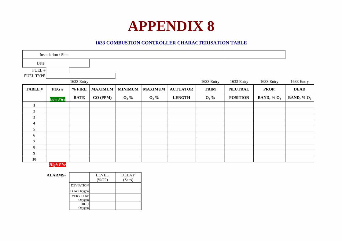
APPENDIX 8
1633 COMBUSTION CONTROLLER CHARACTERISATION TABLE
Installation / Site:
Date:
FUEL # FUEL TYPE
1633 Entry 1633 Entry 1633 Entry 1633 Entry 1633 Entry
TABLE # PEG # % FIRE MAXIMUM MINIMUM MAXIMUM ACTUATOR TRIM NEUTRAL PROP. DEAD
Low Fire RATE CO (PPM) O2 % O2 % LENGTH O2 % POSITION BAND, % O2 BAND, % O2
1 2 3 4 5 6 7 8 9
10 High Fire ALARMS- LEVEL
(%O2)DELAY (Secs)
DEVIATION LOW Oxygen VERY LOW
Oxygen
HIGH Oxygen

August 2009 90 1633 Combustion Controller
INDEX
1
1230 Oxygen Probes ............................................................. 7 1231 Heated Oxygen Probe ................................................... 7 1234 Oxygen sensor
Installing ........................................................................ 22
4
4-20mA Calibration ............................................................. 47
A
Alarm High Oxygen .................................................................. 51 Low Oxygen ................................................................... 51 Very Low Oxygen .......................................................... 52
Alarm Button ....................................................................... 37 Alarm Relays ....................................................................... 39 Alarm Schedule ................................................................... 37 Alarms ........................................................................... 27, 33
Common Alarm .............................................................. 37 Selectable Alarms .......................................................... 38 Summary ........................................................................ 37
Analyser .............................................................................. 15 Mounting ........................................................................ 20
Analyser Description ............................................................. 4 Analyser System .................................................................... 4 Auxiliary Temperature ........................................................ 17
B
Backlight ....................................................................... 39, 40 Back-Up Battery .................................................................. 17 Battery ................................................................................. 17 Battery Replacement ........................................................... 61 Baud Rate ............................................................................ 53 Burner bypass switch ........................................................... 39 Burner By-Pass Switch ........................................................ 33
C
Calender .............................................................................. 45 Calibration
A/D ................................................................................. 60 D/A ................................................................................. 61 Sensor ............................................................................. 33 Test Points ...................................................................... 60
Calibration - Electronics ...................................................... 16 Calibration Check
Connecting ..................................................................... 28 Calibration Checking ........................................................... 16 Calibration Gas Check ......................................................... 34 Centigrade ........................................................................... 49 Cold Start ............................................................................ 60
Commissioning .................................................................... 33 Common Alarms .................................................................. 27 Connections ......................................................................... 23
D
Damping Factor ................................................................... 56 Display Button ..................................................................... 36 Dual Fuel Input
Connecting ...................................................................... 29 Dust in the Flue Gas ............................................................. 34
F
Fahrenheit ............................................................................ 49 Filter Blockage ..................................................................... 63 Filter Purge Pressure Switch ................................................ 12 Filter Purging ....................................................................... 34 Function Select .................................................................... 44
H
Heater Failure ...................................................................... 63 Heater Interlock Relays ....................................................... 25
I
Impedance ............................................................................ 16 Interlock ............................................................................... 25
L
Lower Line ............................................................................ 6 Lower Line Display Functions ............................................. 49
M
Model 1232 Unheated Oxygen Probe .................................... 7 Model 1234 Oxygen Sensor ................................................... 8
O
Offset ................................................................................... 46 Option or Value ................................................................... 44 Outputs ................................................................................... 5 Oxygen Deviation
Oxygen Deviation ........................................................... 52 Oxygen Probe ...................................................................... 10
Installing ......................................................................... 20

August 2009 1633 Combustion Controller 91
P
Power ............................................................................. 31, 33 Power Lamp ........................................................................ 39 Pressure ......................................................................... 15, 50 Print Log
Data ................................................................................ 53 Printer
Connecting ............................................................... 29, 30 Probe
Testing............................................................................ 63 Probe Cable ......................................................................... 26 Pump Replacement .............................................................. 61 Purge ................................................................................... 16
Automatic ....................................................................... 50 Connecting ..................................................................... 28 Freeze Time ................................................................... 50
Purge / Cal Time ................................................................. 50
R
Range of Indication ............................................................... 6 Range of Output 1 ................................................................. 5 Range of Output 2 ................................................................. 5 Reference Air
Connecting ..................................................................... 28 Reference voltage ................................................................ 45 Repairs ................................................................................. 61 RS 232 ................................................................................. 17 RS 485 ................................................................................. 17 Run Mode ............................................................................ 33
S
Selecting the Trim Actuator Span ....................................... 86 Sensor Type ......................................................................... 48
Serial Port ...................................................................... 29, 30 Service Date ......................................................................... 47 Set-Up & Run Modes .......................................................... 44 Set-Up Function Details ....................................................... 45 Set-Up Mode .................................................................. 31, 33 Set-Up Mode Functions ....................................................... 42 Software ................................................................................. 1 Specifications ................................................................... 3, 10 Stratification ........................................................................ 34
T
Technical Enquires ................................................................ 1 Testing A Probe ................................................................... 63 Thermocouple Type
Probe ............................................................................... 48 Thermocouple Type
Auxiluary ........................................................................ 48 Time ..................................................................................... 45 Transmitter 4-20mA ............................................................ 48
V
Version ................................................................................... 1
W
Watchdog Timer .................................................................. 17
Z
Zirconia Sensor .................................................................... 14 Zirconia Sensor Output ........................................................ 65

August 2009 92 1633 Combustion Controller
Declaration of Conformity Application of Council Directives: 89/336/EEC (92/31/EEC) 72/23/EEC Standards to which conformity is declared: EN550011.1:1995 (ISM, Group 1, Class B) EN55014:1995 (Clause 4.2) EN50082-2 (Industrial) EN61010-1 AS61000.4.5:1999 IEC-68-2-2 IEC-68-2-3 AS1099.2.6 Manufacturer’s name: Novatech Controls Pty Ltd Manufacturer’s address: 309 Reserve Road Cheltenham VIC 3192 AUSTRALIA Type of equipment: Oxygen Transmitter
Equipment Class: ISM, Group 1, Class B
Model Number: 1630 Series Transmitter 1231 Oxygen Probe 1234 Oxygen Sensor I hereby declare that the equipment specified herein conforms to the above directive(s) and standards(s).
Full Name: Fraser Chapman Position: R & D Manager

Novatech Controls Pty. Ltd. ABN 57 006 331 700 Conditions of Sale
1. Interpretation In these conditions: (a) `Seller' means Novatech Controls Pty. Ltd.
ABN 57 006 331 700 of 309 Reserve Road, Cheltenham Victoria, 3192 which is the seller of the goods.
(b) `Buyer' means the buyer of the goods specified in the seller's quotation, or in the buyer's order for the goods.
(c) `Goods' means the products and, if any, services specified in Buyer's, orders or Seller's order acknowledgments from time to time.
(d) Nothing in these conditions shall be read or applied so as to exclude, restrict or modify or have the effect of excluding, restricting or modifying any condition, warranty, guarantee, right or remedy implied by law (including the Trade Practices Act 1974) and which by law cannot be excluded, restricted or modified.
2. General These conditions (which shall only be waived in writing signed by the seller) prevail over all conditions of the buyer's order to the extent of any inconsistency. 3. Terms of sale The goods and all other products sold by the seller are sold on these terms and conditions. 4. Seller's quotations Unless previously withdrawn, seller's quotations are open for acceptance within the period stated in them or, when no period is so stated, within 60 days only after its date. The seller reserves the right to refuse any order based on this quotation within 7 days after the receipt of the order. 5. Packing The cost of any special packing and packing materials used in relation to the goods are at the buyer's expense notwithstanding that such cost may have been omitted from any quotation. 6. Shortage The buyer waives any claim for shortage of any goods delivered if a claim in respect for short delivery has not been lodged with seller within seven (7) days from the date of receipt of goods by the buyer. 7. Drawings, etc. (a) All specifications, drawings, and particulars of
weights and dimensions submitted to the buyer are approximate only and any deviation from any of these things does not vitiate any contract with the seller or form grounds for any claim against the seller.
(b) Except as referred to in Clause 13.1 herein, the descriptions, illustrations and performances contained in catalogues, price lists and other advertising matter do not form part of the contract of sale of the goods or of the description applied to the goods.
(c) Where specifications, drawings or other particulars are supplied by the buyer, the seller’s price is made on estimates of quantities required. If there are any adjustments in quantities above or below the quantities estimated by seller and set out in a quotation, then any such increase or decrease are to be adjusted on a unit rate basis according to unit prices set out in the quotation.
8. Performance Any performance figures given by the seller are estimates only. The seller is under no liability for damages for failure of the goods to attain such figures unless specifically guaranteed in writing. Any such written guarantees are subject to the recognised tolerances applicable to such figures.
9. Acknowledgment regarding facilities for repairs or parts
The buyer acknowledges that the seller does not promise or represent that facilities for the repair of the goods, or that parts of the goods are or will be available. The buyer must ensure that each purchaser of the goods from the buyer receives notice that the seller does not promise that facilities for the repair of the goods will be available; or parts for the goods will be available. 10. Delivery (a) The delivery times made known to the buyer
are estimates only and the seller is not be liable for late delivery or non-delivery.
(b) The seller is not be liable for any loss, damage or delay occasioned to the buyer or its customers arising from late or non-delivery or late installation of the goods.
(c) The seller may at its option deliver the goods to the buyer in any number of instalments unless there is an agreement in writing between the parties to the effect that the buyer will not take delivery by instalments.
(d) If the seller delivers any of the goods by instalments, and any one of those instalments is defective for any reason: (i) it is not a repudiation of the contract of
sale formed by these conditions; and (ii) the defective instalment is a severable
breach that gives rise only to a claim for compensation.
11. Passing of risk Risk in the goods passes to the buyer upon the earlier of: (a) actual or constructive delivery of the goods to
the buyer; or (b) collection of the goods from the seller or any
bailee or agent of the seller by the buyer's agent, carrier or courier.
12. Loss or damage in transit (a) The seller is not responsible to the buyer or any
person claiming through the buyer for any loss or damage to goods in transit caused by any event of any kind by any person (whether or not the seller is legally responsible for the person who caused or contributed to that loss or damage).
(b) The seller must provide the buyer with such assistance as may be necessary to press claims on carriers so long as the buyer: (i) has notified the seller and the carriers in
writing immediately after loss or damage is discovered on receipt of goods; and
(ii) lodges a claim for compensation on the carrier within three (3) days of the date of receipt of the goods.
13. Guarantee 13.1 The seller's liability for goods manufactured by
it is limited to making good any defects by repairing the defects or at the seller's option by replacement, within a period as specified in Seller's catalogues or other product literature for specified cases or not exceeding twelve (12) calendar months after the goods have been dispatched (whichever is the lesser period) so long as:
(a) defects have arisen solely from faulty materials or workmanship;
(b) the damage does not arise from: (i) improper adjustment, calibration or
operation by the buyer; (ii) the use of accessories including
consumables, hardware, or software which
were not manufactured by or approved in writing by the seller;
(iii) any contamination or leakages caused or induced by the buyer;
(iv) any modifications of the goods which were not authorised in writing by the seller;
(v) any misuse of the goods by the buyer or anyone for whom the buyer has legal responsibility (including a minor);
(vi) any use or operation of the goods outside of the physical, electrical or environmental specifications of the goods;
(vii) inadequate or incorrect site preparation; and
(viii) inadequate or improper maintenance of the goods.
(ix) fair wear and tear of the product in an environment in respect of which the Seller has informed the Buyer in catalogues or other product literature that the period of usefulness of the product is likely to be shorter that twelve 12 months.
(c) the goods have not received maltreatment, inattention or interference;
(d) accessories of any kind used by the buyer are manufactured by or approved by the seller;
(e) the seals of any kind on the goods remain unbroken; and
(f) the defective parts are promptly returned free of cost to the seller.
13.2 The seller is not liable for and the buyer releases the seller from any claims in respect of faulty or defective design of any goods supplied unless such design has been wholly prepared by the seller and the responsibility for any claim has been specifically accepted by the seller in writing. In any event the seller’s liability under this paragraph is limited strictly to the replacement of defective parts in accordance with para 13.1 of these conditions.
13.3 Except as provided in these conditions, all express and implied warranties, guarantees and conditions under statute or general law as to merchantability, description, quality, suitability or fitness of the goods for any purpose or as to design, assembly, installation, materials or workmanship or otherwise are expressly excluded. The seller is not liable for physical or financial injury, loss or damage or for consequential loss or damage of any kind arising out of the supply, layout, assembly, installation or operation of the goods or arising out of the seller’s negligence or in any way whatsoever.
14. Seller's liability 14.1 The seller's liability for a breach of a condition
or warranty implied by Div 2 of Pt V of the Trade Practices Act 1974 (other than s 69) is limited to:
(a) in the case of goods, any one or more of the following: (i) the replacement of the goods or the supply
of equivalent goods; (ii) the repair of the goods; (iii) the payment of the cost of replacing the
goods or of acquiring equivalent goods; (iv) the payment of the cost of having the
goods repaired; or (b) in the case of services:
(i) the supplying of the services again; or (ii) the payment of the cost of having the
services supplied again.

Novatech Controls Pty. Ltd. ABN 57 006 331 700 Conditions of Sale
14.2 The seller's liability under s 74H of the Trade
Practices Act 1975 is expressly limited to a liability to pay to the purchaser an amount equal to:
(a) the cost of replacing the goods; (b) the cost of obtaining equivalent goods; or (c) the cost of having the goods repaired,
whichever is the lowest amount. 15. Prices (a) Unless otherwise stated all prices quoted by
vendor are net, exclusive of Goods and Services Tax (GST) and the buyer agrees to pay to the seller any GST in addition to the price.
(b) Prices quoted are those ruling at the date of issue of quotation and are based on rates of freight, insurance, customs duties, exchange, shipping expenses, sorting and stacking charges, cartage, the quotation, cost of materials, wages and other charges affecting the cost of production ruling on the date is made.
(c) If the seller makes any alterations to the price of the goods or to any of their inputs either before acceptance of or during the currency of the contract, these alterations are for the buyer’s account.
16. Payment The purchase price in relation to goods is payable net and payment of the price of the goods must be made on or before the thirtieth day from the date of invoice unless other terms of payment are expressly stated in these conditions in writing. 17. Rights in relation to goods (Romalpa clause) The seller reserves the following rights in relation to the goods until all accounts owed by the buyer to the seller are fully paid: (a) ownership of the goods; (b) to enter the buyer's premises (or the premises of
any associated company or agent where the goods are located) without liability for trespass or any resulting damage and retake possession of the goods; and
(c) to keep or resell the goods including any goods repossessed pursuant to 17(b) above;
If the goods are resold, or goods manufactured using the goods are sold, by the buyer, the buyer shall hold
such part of the proceeds of any such sale as represents the invoice price of the goods sold or used in the manufacture of the goods sold in a separate identifiable account as the beneficial property of the seller and shall pay such amount to the seller upon request. Notwithstanding the provisions above the seller shall be entitled to maintain an action against the buyer for the purchase price and the risk of the goods shall pass to the buyer upon delivery. 18. Buyer's property Any property of the buyer under the seller’s possession, custody or control is completely at the buyer’s risk as regards loss or damage caused to the property or by it. 19. Storage The seller reserves the right to make a reasonable charge for storage if delivery instructions are not provided by the buyer within fourteen days of a request by the seller for such instructions. The parties agree that the seller may charge for storage from the first day after the seller requests the buyer to provide delivery instructions. 20. Returned goods (a) The seller will not be under any duty to accept
goods returned by the buyer and will do so only on terms to be agreed in writing in each individual case.
(b) If the seller agrees to accept returned goods from the buyer under para (a) of this clause, the buyer must return the goods to the seller at the seller’s place of business referred to at the head of these conditions.
21. Goods sold All goods to be supplied by the seller to the buyer are as described on the purchase order agreed by the seller and the buyer and the description on such purchase order modified as so agreed prevails over all other descriptions including any specification or enquiry of the buyer. 22. Cancellation No order may be cancelled except with consent in writing and on terms which will indemnify the seller against all losses. 23. Indemnity The buyer indemnifies on a continuing basis on a fully indemnity basis the seller from and against any
liability, loss, expense or demand for or arising from any false, misleading, deceptive or misdescriptive representation or statement made by the buyer in respect of the goods to any person. This indemnity survives termination of this agreement by either part for any reason. 24. Exclusion of representations and
arrangements Except as referred to in Clause 13.1herein, these terms and conditions supersede and exclude all prior and other discussions, representations (contractual or otherwise) and arrangements relating to the supply of the goods or any part of the goods including, but without limiting the generality of the foregoing, those relating to the performance of the goods or any part of the goods or the results that ought to be expected from using the goods. 25. No waiver The failure of any part to enforce the provisions of this agreement or to exercise any rights expressed in this agreement is not to be a waiver of such provisions or rights an does not affect the enforcement of this agreement. 26. Force Majeure If by reason of any fact, circumstance, matter or thing beyond the reasonable control of the seller, the seller is unable to perform in whole or in part any obligation under this agreement the seller is relieved of that obligation under this agreement to the extent and for the period that it is so unable to perform and is not liable to the buyer in respect of such inability. 27. Buyer Acknowledgement The Buyer acknowledges that the above provisions of these Conditions of Sale are reasonable and reflected in the price and the Buyer accepts the risks of the Buyer associated with these Conditions of sale and/or shall issue accordingly. 28. Place of contract (a) The contract for sale of the goods is made in the
state of Victoria Australia. (b) The parties submit all disputes arising between
them to the courts of such state and any court competent to hear appeals from those courts of first instance.