1606 ieee transactions on power delivery, …paginas.fe.up.pt/~ee04109/documentos e imagens/10 -...
TRANSCRIPT

1606 IEEE TRANSACTIONS ON POWER DELIVERY, VOL. 23, NO. 3, JULY 2008
Dynamic Performance Comparison ofSynchronous Condenser and SVC
Sercan Teleke, Tarik Abdulahovic, Torbjörn Thiringer, and Jan Svensson, Member, IEEE
Abstract—In this paper, a comparison of the dynamic per-formance between a conventional synchronous condenser, asuperconducting synchronous condenser, and a static var compen-sator (SVC) is made in a grid setup by simulating different casesthat affect the performance of reactive power compensation. Theresults show that the SVC injects more reactive power and has abetter dynamic performance during faults that cause a moderateor minor voltage drop on its terminals, such as single-phase toground faults in weak grids. The synchronous condensers, onthe other hand, bring the voltage to the nominal value quickerand show a better dynamic performance for severe faults such asthree phase to ground faults in stiff grids. The superconductingsynchronous condenser injects up to 45% more reactive powercompared to the conventional synchronous condenser during anearby three phase to ground fault.
Index Terms—Static var compensator (SVC), superconductingsynchronous condenser, synchronous condenser.
I. INTRODUCTION
REACTIVE power compensation is defined as the reactivepower management with the aim of improving the perfor-
mance of ac power systems [1]. Reactive power compensation isviewed from two aspects: load compensation and voltage sup-port. In load compensation, the objectives are to increase thepower factor, to balance the load and to eliminate current har-monics from nonlinear industrial loads [2], [3]. Voltage supportreduces voltage fluctuation at a given terminal of a transmis-sion line [1] and improves the stability of the ac system by in-creasing the maximum active power that can be transmitted. Italso helps to maintain a substantially flat voltage profile at alllevels of power transmission, increases transmission efficiency,controls steady-state and temporary over-voltages [4], and helpsto avoid catastrophic blackouts [5], [6].
As reactive power compensation is an effective way to im-prove the electric power network, there is a need for controlledreactive power compensation which can be done either by syn-chronous condensers or static var compensators (SVCs), whichutilize power electronic devices.
Manuscript received April 16, 2007; revised September 9, 2007. This workwas supported by ABB FACTS, Västerås, Sweden. Paper no. TPWRD-00216-2007.
S. Teleke is with the Department of Electrical and Computer Engi-neering, North Carolina State University, Raleigh, NC 27606 USA (e-mail:[email protected]).
T. Abdulahovic and T. Thiringer are with the Department of Energy and En-vironment, Chalmers University of Technology, Göteborg SE-412 96, Sweden(e-mail: [email protected]; [email protected]).
J. Svensson is with ABB FACTS, Västerås SE-721 64, Sweden (e-mail: [email protected]).
Digital Object Identifier 10.1109/TPWRD.2007.916109
Fig. 1. Single-line diagram with a synchronous condenser connected to grid.
The purpose of this paper is to compare the dynamic perfor-mance of a conventional synchronous condenser, a supercon-ducting synchronous condenser (SuperVAR) and an SVC duringvarious grid set ups and fault types.
II. PRESENTATION OF REACTIVE
POWER COMPENSATION DEVICES
In this section, the synchronous condenser and the SVC arepresented.
A. Synchronous Condensers
Synchronous condensers have played a major role in voltageand reactive power control for more than 50 years [7]–[12].In this section, conventional and superconducting synchronouscondensers are described.
1) Conventional Synchronous Condenser: A synchronouscondenser is a synchronous motor without any mechanical load[13]. Its field is controlled by a voltage regulator to generate orabsorb reactive power to support a system’s voltage or to keepthe system power factor at a specified level. Synchronous con-densers installation and operation are identical to large electricmachines. A single-line diagram with a synchronous condenseris shown in Fig. 1.
2) Superconducting Synchronous Condenser (SuperVAR):Only the field winding of the synchronous condenser utilizesa high-temperature superconductor winding cooled with acryocooler subsystem to about 35–40 K [14]. The cryocoolermodules are placed in a stationary frame and helium gas isused to cool the rotor of the machine. The stator winding isa conventional copper winding. However, the winding is notplaced in conventional iron core teeth, since the iron coresaturates due to the high magnetic field, typically 1.5–2.0 T,imposed by the field winding. Only the stator yoke (back iron)uses magnetic iron to provide magnetic shielding and to carryflux between adjacent poles. The absence of iron in most ofthe magnetic circuits in these machines results in a very lowsynchronous reactance (typically 0.3–0.5 p.u.). More details of
0885-8977/$25.00 © 2008 IEEE
Authorized licensed use limited to: UNIVERSIDADE DO PORTO. Downloaded on March 10,2010 at 11:57:01 EST from IEEE Xplore. Restrictions apply.

TELEKE et al.: DYNAMIC PERFORMANCE COMPARISON OF SYNCHRONOUS CONDENSER AND SVC 1607
Fig. 2. Single-line diagram of the SVC used in the simulations.
the SuperVAR, including performance features, design config-urations, and maintenance challenges can be found in [15].
B. Static VAR Compensator (SVC)
Maintenance requirements of conventional synchronous con-densers rose interest in the development of static VAR systems[16]. Several papers have studied modeling [17]–[20] and theapplication of SVCs [16], [21], [22]. A typical SVC, composedof thyristor-switched capacitors (TSCs) and thyristor-controlledreactors (TCRs), together with filters, is shown in Fig. 2. Thefilters (FCs) are used to remove low-frequency harmonics pro-duced by the TCR and to produce reactive power. With propercoordination of the capacitor switching and reactor control, thereactive power output can be varied continuously between thecapacitive and inductive ratings of the equipment.
The compensator operates to regulate the voltage of the trans-mission system at a selected terminal. However, the maximumobtainable capacitive current decreases linearly with the systemvoltage since the SVC becomes a fixed capacitor when the max-imum capacitive output is reached. Therefore, the conventionalthyristor-controlled SVC rapidly deteriorates its voltage supportcapability with the decrease of system voltage.
III. SETUP OF PERFORMANCE STUDY
A. Setup of Compensators
For comparison of the SuperVAR [15], the conventional syn-chronous condenser and the SVC, a grid setup using PSCAD ismade, where the parameters are given in the Appendix. The con-ventional synchronous condenser and the SuperVAR are usingthe type DC2A exciter and the type ST1A exciter, respectively.The 32 Mvar SVC consists of two TSC banks where each bankhas 35.8% of the rated power, two 3rd and 5th harmonic filterswhere each carries 10.2% of the rated power and two 7th and11th harmonic filters where each carry 4% of the rated power.For reactive power consumption, one TCR with the size of 38%of the rated power is employed. In the connection of the SVCto the network, a 10% coupling transformer with the sizeof rated reactive power is used, where the high voltage side wasconnected with Y grounded.
B. Grid Setup
The grid setup used to compare the performance of the Su-perVAR, the conventional synchronous condenser and the SVC,is shown in Fig. 3. The setup shows a factory, where the mainload consists of two sets of 50 induction machines of 500 HP
Fig. 3. Single-line diagram of the used grid setup.
with 0.9 power factor; 10 kV with inertia constant of 2 s. Theseunits are connected to a 36 kV substation via 25 MVA trans-formers (10% leakage reactance, 36/10 kV). Moreover, a resis-tive and an inductive load of 16 MW and 12 Mvar are also con-nected to the substation via a 25 MVA transformer (10%, 36/10kV). A capacitor bank of 8 Mvar is connected to each 10 kVload bus in order to keep the 10 kV bus within 95% to 100%of nominal voltage during full load operation. The short-circuitratio (SCR), which is the ratio between the short-circuit powermeasured at the 36-kV bus and the load total apparent power, is3.9 which represents a medium strong system.
Four 8 MVA synchronous condensers or one 32 Mvar SVCare/is connected to the 36 kV bus via a 32 MVA transformer(10%, 13.8/36 kV), to provide reactive power compensation, es-pecially in case of faults occurring in the network that transfersthe power from the generator to the factory. The network con-sists of two 200 km lines with an X/R ratio of 15 where the faultoccurs in one of the lines, which will cause the breakers to openafter a 250 ms delay, and accordingly to disconnect the faultedline and connect it back 500 ms after the fault is cleared.
In the 36 kV substation, there is a 70 MVA step down trans-former (10%, 130/36 kV) that adapts the voltage level to thefactory. Finally, the 130 kV source is an infinite bus.
IV. SIMULATION RESULTS FROM THE STUDY
To compare the synchronous condensers with the SVC, theparameters of the grid have been altered. The configurationwithout any reactive power compensation is denoted by WOC.The cases with conventional synchronous condensers andSuperVARs connected to the 36 kV bus are denoted by CONand SCO, respectively. Finally, the configuration with the SVCconnected to the 36 kV bus is denoted by SVC.
A. Different Fault Types
In this section, single-phase-to-ground, two-phase-to-ground,and three-phase-to-ground faults are simulated and analyzed.
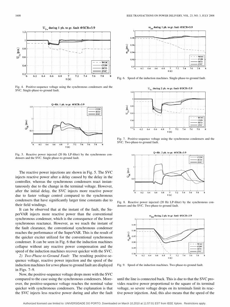
1) Single Phase to Ground Fault: To determine the perfor-mance of the different compensators, a single phase to groundfault in the middle of one of the two lines is applied. The re-sulting positive-sequence voltage, reactive power injection andthe speed of the induction machines are displayed in Figs. 4–6.
From Fig. 4, it is clear that without any reactive power com-pensation, the system collapses and with compensation it sur-vives. Moreover, after the fault, the SVC brings the voltage backto 1 p.u. quickly and accurately.
Authorized licensed use limited to: UNIVERSIDADE DO PORTO. Downloaded on March 10,2010 at 11:57:01 EST from IEEE Xplore. Restrictions apply.
1608 IEEE TRANSACTIONS ON POWER DELIVERY, VOL. 23, NO. 3, JULY 2008
Fig. 4. Positive-sequence voltage using the synchronous condensers and theSVC. Single-phase-to-ground fault.
Fig. 5. Reactive power injected (20 Hz LP-filter) by the synchronous con-densers and the SVC. Single-phase-to-ground fault.
The reactive power injections are shown in Fig. 5. The SVCinjects reactive power after a delay caused by the delay in thecontroller, whereas the synchronous condensers react instan-taneously due to the change in the terminal voltage. However,after the initial delay, the SVC injects more reactive powerdue to faster voltage control compared to the synchronouscondensers that have significantly larger time constants due totheir field windings.
It can be observed that at the instant of the fault, the Su-perVAR injects more reactive power than the conventionalsynchronous condenser, which is the consequence of the lowersynchronous reactance. However, as we reach the instant ofthe fault clearance, the conventional synchronous condenserreaches the performance of the SuperVAR. This is the result ofthe quicker exciter utilized for the conventional synchronouscondenser. It can be seen in Fig. 6 that the induction machinescollapse without any reactive power compensation and thespeed of the induction machines recover quicker with the SVC.
2) Two-Phase-to-Ground Fault: The resulting positive-se-quence voltage, reactive power injection and the speed of theinduction machines for a two phase to ground fault are displayedin Figs. 7–9.
Now, the positive-sequence voltage drops more with the SVCcompared to the case using the synchronous condensers. More-over, the positive-sequence voltage reaches the nominal valuequicker with synchronous condensers. The explanation is thatthe SVC injects less reactive power during and after the fault
Fig. 6. Speed of the induction machines. Single-phase-to-ground fault.
Fig. 7. Positive-sequence voltage using the synchronous condensers and theSVC. Two-phase-to-ground fault.
Fig. 8. Reactive power injected (20 Hz LP-filter) by the synchronous con-densers and the SVC. Two-phase-to-ground fault.
Fig. 9. Speed of the induction machines. Two-phase-to-ground fault.
until the line is connected back. This is due to that the SVC pro-vides reactive power proportional to the square of its terminalvoltage, so severe voltage drops on its terminals limit its reac-tive power injection. And, this also means that the speed of the
Authorized licensed use limited to: UNIVERSIDADE DO PORTO. Downloaded on March 10,2010 at 11:57:01 EST from IEEE Xplore. Restrictions apply.
TELEKE et al.: DYNAMIC PERFORMANCE COMPARISON OF SYNCHRONOUS CONDENSER AND SVC 1609
Fig. 10. Positive-sequence voltages in the presence of the synchronous con-densers and the SVC. Three-phase-to-ground fault.
Fig. 11. Reactive power injected (20 Hz LP-filter) by the synchronous con-densers and the SVC. Three-phase-to-ground fault.
Fig. 12. Speed of the induction machines. Three-phase-to-ground fault.
induction machines drops more with the SVC due to the lowerpositive-sequence voltage.
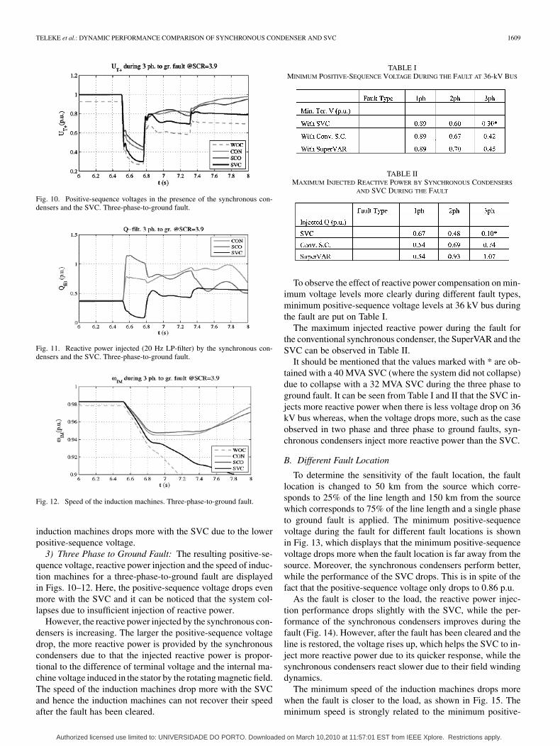
3) Three Phase to Ground Fault: The resulting positive-se-quence voltage, reactive power injection and the speed of induc-tion machines for a three-phase-to-ground fault are displayedin Figs. 10–12. Here, the positive-sequence voltage drops evenmore with the SVC and it can be noticed that the system col-lapses due to insufficient injection of reactive power.
However, the reactive power injected by the synchronous con-densers is increasing. The larger the positive-sequence voltagedrop, the more reactive power is provided by the synchronouscondensers due to that the injected reactive power is propor-tional to the difference of terminal voltage and the internal ma-chine voltage induced in the stator by the rotating magnetic field.The speed of the induction machines drop more with the SVCand hence the induction machines can not recover their speedafter the fault has been cleared.
TABLE IMINIMUM POSITIVE-SEQUENCE VOLTAGE DURING THE FAULT AT 36-kV BUS
TABLE IIMAXIMUM INJECTED REACTIVE POWER BY SYNCHRONOUS CONDENSERS
AND SVC DURING THE FAULT
To observe the effect of reactive power compensation on min-imum voltage levels more clearly during different fault types,minimum positive-sequence voltage levels at 36 kV bus duringthe fault are put on Table I.
The maximum injected reactive power during the fault forthe conventional synchronous condenser, the SuperVAR and theSVC can be observed in Table II.
It should be mentioned that the values marked with * are ob-tained with a 40 MVA SVC (where the system did not collapse)due to collapse with a 32 MVA SVC during the three phase toground fault. It can be seen from Table I and II that the SVC in-jects more reactive power when there is less voltage drop on 36kV bus whereas, when the voltage drops more, such as the caseobserved in two phase and three phase to ground faults, syn-chronous condensers inject more reactive power than the SVC.
B. Different Fault Location
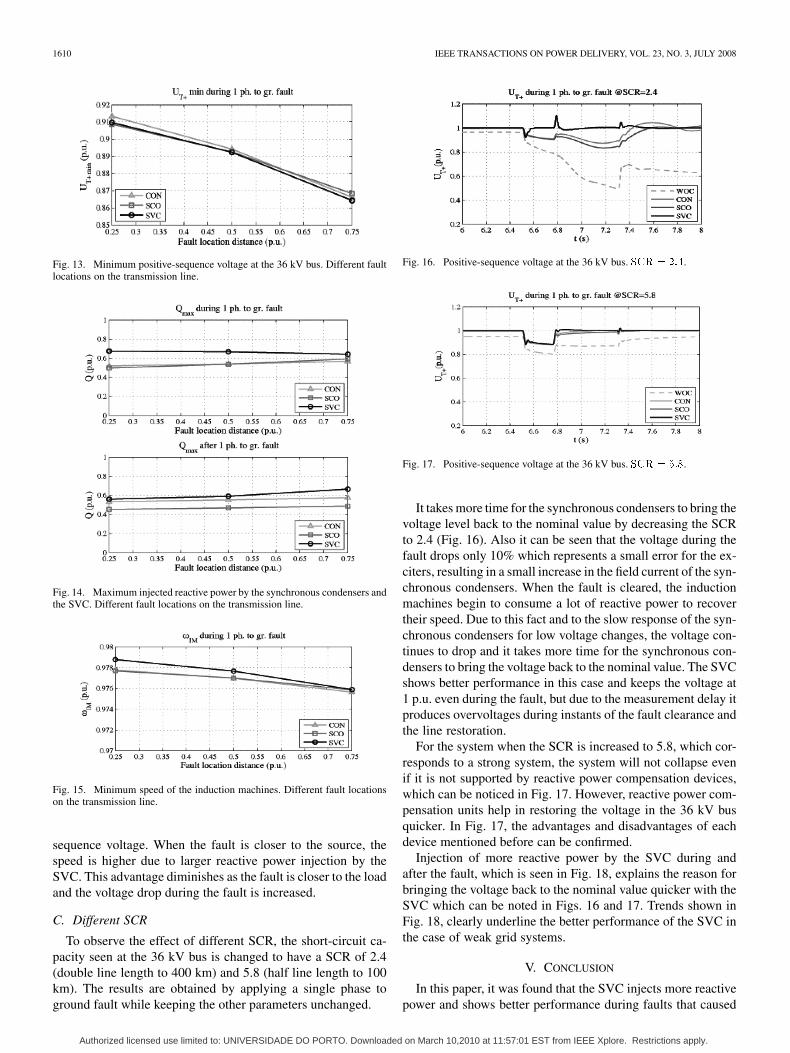
To determine the sensitivity of the fault location, the faultlocation is changed to 50 km from the source which corre-sponds to 25% of the line length and 150 km from the sourcewhich corresponds to 75% of the line length and a single phaseto ground fault is applied. The minimum positive-sequencevoltage during the fault for different fault locations is shownin Fig. 13, which displays that the minimum positive-sequencevoltage drops more when the fault location is far away from thesource. Moreover, the synchronous condensers perform better,while the performance of the SVC drops. This is in spite of thefact that the positive-sequence voltage only drops to 0.86 p.u.
As the fault is closer to the load, the reactive power injec-tion performance drops slightly with the SVC, while the per-formance of the synchronous condensers improves during thefault (Fig. 14). However, after the fault has been cleared and theline is restored, the voltage rises up, which helps the SVC to in-ject more reactive power due to its quicker response, while thesynchronous condensers react slower due to their field windingdynamics.
The minimum speed of the induction machines drops morewhen the fault is closer to the load, as shown in Fig. 15. Theminimum speed is strongly related to the minimum positive-
Authorized licensed use limited to: UNIVERSIDADE DO PORTO. Downloaded on March 10,2010 at 11:57:01 EST from IEEE Xplore. Restrictions apply.
1610 IEEE TRANSACTIONS ON POWER DELIVERY, VOL. 23, NO. 3, JULY 2008
Fig. 13. Minimum positive-sequence voltage at the 36 kV bus. Different faultlocations on the transmission line.
Fig. 14. Maximum injected reactive power by the synchronous condensers andthe SVC. Different fault locations on the transmission line.
Fig. 15. Minimum speed of the induction machines. Different fault locationson the transmission line.
sequence voltage. When the fault is closer to the source, thespeed is higher due to larger reactive power injection by theSVC. This advantage diminishes as the fault is closer to the loadand the voltage drop during the fault is increased.
C. Different SCR
To observe the effect of different SCR, the short-circuit ca-pacity seen at the 36 kV bus is changed to have a SCR of 2.4(double line length to 400 km) and 5.8 (half line length to 100km). The results are obtained by applying a single phase toground fault while keeping the other parameters unchanged.
Fig. 16. Positive-sequence voltage at the 36 kV bus. ��� � ���.
Fig. 17. Positive-sequence voltage at the 36 kV bus. ��� � ���.
It takes more time for the synchronous condensers to bring thevoltage level back to the nominal value by decreasing the SCRto 2.4 (Fig. 16). Also it can be seen that the voltage during thefault drops only 10% which represents a small error for the ex-citers, resulting in a small increase in the field current of the syn-chronous condensers. When the fault is cleared, the inductionmachines begin to consume a lot of reactive power to recovertheir speed. Due to this fact and to the slow response of the syn-chronous condensers for low voltage changes, the voltage con-tinues to drop and it takes more time for the synchronous con-densers to bring the voltage back to the nominal value. The SVCshows better performance in this case and keeps the voltage at1 p.u. even during the fault, but due to the measurement delay itproduces overvoltages during instants of the fault clearance andthe line restoration.
For the system when the SCR is increased to 5.8, which cor-responds to a strong system, the system will not collapse evenif it is not supported by reactive power compensation devices,which can be noticed in Fig. 17. However, reactive power com-pensation units help in restoring the voltage in the 36 kV busquicker. In Fig. 17, the advantages and disadvantages of eachdevice mentioned before can be confirmed.
Injection of more reactive power by the SVC during andafter the fault, which is seen in Fig. 18, explains the reason forbringing the voltage back to the nominal value quicker with theSVC which can be noted in Figs. 16 and 17. Trends shown inFig. 18, clearly underline the better performance of the SVC inthe case of weak grid systems.
V. CONCLUSION
In this paper, it was found that the SVC injects more reactivepower and shows better performance during faults that caused
Authorized licensed use limited to: UNIVERSIDADE DO PORTO. Downloaded on March 10,2010 at 11:57:01 EST from IEEE Xplore. Restrictions apply.

TELEKE et al.: DYNAMIC PERFORMANCE COMPARISON OF SYNCHRONOUS CONDENSER AND SVC 1611
Fig. 18. Maximum injected reactive power by the synchronous condensers andthe SVC. Various SCRs.
TABLE IIIPARAMETERS OF CONVENTIONAL SYNCHRONOUS CONDENSER
TABLE IVSATURATION DATA OF CONVENTIONAL SYNCHRONOUS CONDENSER
TABLE VEXCITER PARAMETERS OF CONVENTIONAL SYNCHRONOUS CONDENSER
less voltage drop on its terminals, such as single phase to groundfaults or faults in weak grids. However, during severe faults,such as three phase to ground faults and severe faults in stiffgrids, the synchronous condensers perform better and bring theterminal voltage to the nominal value quicker. This is especiallytrue for the case with the SuperVAR, which injects up to 45%more reactive power compared to the conventional synchronouscondenser.
Moreover, for future studies, it will be very interesting to ex-pand the analysis and comparison to include the STATCOM andthe authors are planning to present a paper on this subject.
APPENDIX
Tables III and IV are used for the conventional synchronouscondenser.
Table V is used for the exciter DC2A of the conventionalsynchronous condenser.
Table VI is used for calculating parameters for the SuperVAR.
Table VII is used for the exciter ST1A of the SuperVAR.
TABLE VIPARAMETERS OF SUPERVAR
TABLE VIIEXCITER PARAMETERS FOR SUPERVAR
REFERENCES
[1] T. J. E. Miller, Reactive Power Control in Electric Power Systems.New York: Wiley, 1982.
[2] E. Wanner, R. Mathys, and M. Hausler, “Compensation systems forindustry,” Brown Boveri Rev., vol. 70, pp. 330–340, Sep./Oct. 1983.
[3] G. Bonnard, “The problems posed by electrical power supply to in-dustrial installations,” Proc. Inst. Elect. Eng. B, vol. 132, pp. 335–340,Nov. 1985.
[4] A. Hammad and B. Roesle, “New roles for static VAR compensators intransmission systems,” Brown Boveri Rev., vol. 73, pp. 314–320, Jun.1986.
[5] N. Grudinin and I. Roytelman, “Heading off emergencies in large elec-tric grids,” IEEE Spectr., vol. 34, no. 4, pp. 43–47, Apr. 1997.
[6] C. W. Taylor, “Improving grid behaviour,” IEEE Spectr., vol. 36, no.6, pp. 40–45, Jun. 1999.
[7] J. A. Oliver, B. J. Ware, and R. C. Carruth, “345 MVA fully water-cooled synchronous condenser for Dumont station part I: Applicationconsiderations,” IEEE Trans. Power App. Syst., vol. PAS-90, no. 6, pp.2758–2764, Nov. 1971.
[8] H. A. Landhult and B. Nordberg, “345 MVA fully water-cooled syn-chronous condenser for Dumont station part II. design, constructionand testing,” IEEE Trans. Power App. Syst., vol. PAS-90, no. 6, pp.2765–2777, Nov. 1971.
[9] Y. Katsuya, Y. Mitani, and K. Tsuji, “Power system stabilizationby synchronous condenser with fast excitation control,” in Proc. Int.Conf. Power Syst. Technol., Perth, Australia, Dec. 4–7, 2000, vol. 3,pp. 1563–1568.
[10] J. M. Van Coller, R. G. Koch, T. D. J. Hennessy, R. Coney, and G.Topham, “The effect of a synchronous condenser on the voltage dipenvironment-as expressed in terms of the eskom ABCD dip chart,” inProc. IEEE. AFRICON, Stellenbosch, South Africa, Sep. 24–27, 1996,vol. 2, pp. 620–625.
[11] S. Nakamura, T. Yamada, T. Nomura, M. Iwamoto, Y. Shindo, S.Nose, A. Ishihara, and H. Fujino, “30 MVA superconducting syn-chronous condenser: Design and it’s performance test results,” IEEETrans. Magn., vol. M-21, no. 2, pp. 783–790, Mar. 1985.
[12] S. Kalsi, D. Madura, and M. Ross, “Performance of superconductordynamic synchronous condenser on an electric grid,” in Proc. IEEETransm. Distribution Conf. Exhibit., 2005, pp. 1–5.
[13] C. Corvin, “SLAC synchronous condenser,” in Proc. Particle Acceler-ator Conf., Dallas, TX, May 1–5, 1995, vol. 4, pp. 2114–2116.
[14] S. Kalsi, K. Weeber, H. Takasue, C. Lewis, H.-W. Neumueller, andR. D. Blaugher, “Development status of rotating machines employingsuperconducting field windings,” Proc. IEEE, vol. 92, no. 10, pp.1688–1704, Oct. 2004.
[15] S. Kalsi, D. Madura, R. Howard, G. Snitchler, T. MacDonald, D.Bradshaw, I. Grant, and M. Ingram, “Superconducting dynamic syn-chronous condenser for improved grid voltage support,” presented atthe IEEE Transm. Distrib. Conf., Dallas, TX, Sep. 10, 2003.
[16] T. R. Boyko, K. A. Ewy, M. P. Hausler, A. Kara, C. S. Miller, D. R. Tor-genson, and E. P. Weber, “Integration of a static var system into Fargosubstation,” in Proc. Int. Conf. AC DC Power Transmission, London,U.K., Sep. 17–20, 1991, pp. 241–247.
Authorized licensed use limited to: UNIVERSIDADE DO PORTO. Downloaded on March 10,2010 at 11:57:01 EST from IEEE Xplore. Restrictions apply.
1612 IEEE TRANSACTIONS ON POWER DELIVERY, VOL. 23, NO. 3, JULY 2008
[17] A. M. Gole and V. K. Sood, “A static compensator model for use withelectromagnetic transients simulation programs,” IEEE Trans. PowerDel., vol. 5, no. 3, pp. 1398–1407, Jul. 1990.
[18] S. Lefebvre and L. Gerin-Lajoie, “A static compensator model for theEMTP,” IEEE Trans. Power Syst., vol. 7, no. 2, pp. 477–486, May 1992.
[19] S. Y. Lee, S. Bhattacharya, T. Lejonberg, A. E. Hammad, and S.Lefebvre, “Detailed modeling of static var compensators using theelectromagnetic transients program (EMTP),” IEEE Trans. PowerDel., vol. 7, no. 2, pp. 836–847, Apr. 1992.
[20] IEEE Special Stability Controls Working Group, “Static VAR compen-sator models for power flow and dynamic performance simulation,”IEEE Trans. Power Syst., vol. 9, no. 1, pp. 229–240, Feb. 1994.
[21] L. Gerin-Lajoie, G. Scott, S. Breault, E. V. Larsen, D. H. Baker, andA. F. Imece, “Hydro-Quebec multiple SVC application control stabilitystudy,” IEEE Trans. Power Del., vol. 5, no. 3, pp. 1543–1551, Jul. 1990.
[22] A. E. Hammad, Applications of Static Var Compensators in UtilityPower Systems 1987, pp. 28–35, Application of Static Var Systems forSystem Dynamic Performance, IEEE 87TH0187-5-PWR.
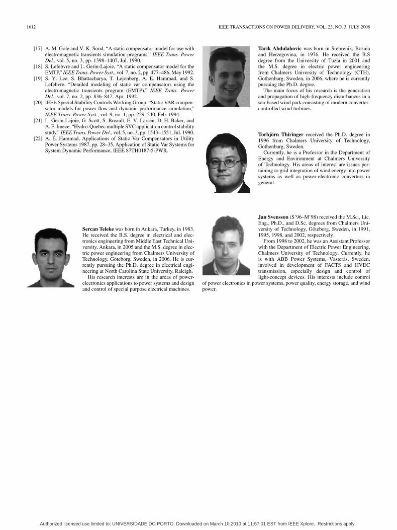
Sercan Teleke was born in Ankara, Turkey, in 1983.He received the B.S. degree in electrical and elec-tronics engineering from Middle East Technical Uni-versity, Ankara, in 2005 and the M.S. degree in elec-tric power engineering from Chalmers University ofTechnology, Göteborg, Sweden, in 2006. He is cur-rently pursuing the Ph.D. degree in electrical engi-neering at North Carolina State University, Raleigh.
His research interests are in the areas of power-electronics applications to power systems and designand control of special purpose electrical machines.
Tarik Abdulahovic was born in Srebrenik, Bosniaand Herzegovina, in 1976. He received the B.Sdegree from the University of Tuzla in 2001 andthe M.S. degree in electric power engineeringfrom Chalmers University of Technology (CTH),Gothenburg, Sweden, in 2006, where he is currentlypursuing the Ph.D. degree.
The main focus of his research is the generationand propagation of high-frequency disturbances in asea-based wind park consisting of modern converter-controlled wind turbines.
Torbjörn Thiringer received the Ph.D. degree in1996 from Chalmers University of Technology,Gothenburg, Sweden.
Currently, he is a Professor in the Department ofEnergy and Environment at Chalmers Universityof Technology. His areas of interest are issues per-taining to grid integration of wind energy into powersystems as well as power-electronic converters ingeneral.
Jan Svensson (S’96–M’98) received the M.Sc., Lic.Eng., Ph.D., and D.Sc. degrees from Chalmers Uni-versity of Technology, Göteborg, Sweden, in 1991,1995, 1998, and 2002, respectively.
From 1998 to 2002, he was an Assistant Professorwith the Department of Electric Power Engineering,Chalmers University of Technology. Currently, heis with ABB Power Systems, Västerås, Sweden,involved in development of FACTS and HVDCtransmission, especially design and control oflight-concept devices. His interests include control
of power electronics in power systems, power quality, energy storage, and windpower.
Authorized licensed use limited to: UNIVERSIDADE DO PORTO. Downloaded on March 10,2010 at 11:57:01 EST from IEEE Xplore. Restrictions apply.