16 powermodules reliablepowerelectronicsfor windmillgenerators pdf/reliable... · 2012-04-01 · 16...
TRANSCRIPT

16 POWER MODULES www.semikron.com
Issue 2 2008 Power Electronics Europe
Reliable Power Electronics forWindmill GeneratorsIn the megawatt range, high-power electronics applications need powerful semiconductors. However, eventhe largest semiconductors available today are still not strong enough for some applications. It is thereforenecessary to connect them in parallel. Dejan Schreiber, Senior Applications Manager, SEMIKRON,Nuremberg, Germany
One possible solution is discussed inthis context: power electronics assembly,IGBT base units containing IGBTs anddiodes, heatsinks, DC-link capacitors,drivers and protection, auxiliary powersupply and a PWM controller (oneindependent unit), arranged into a three-phase inverter. Such units can beconnected in parallel, for example for afour-quadrant drive windmill withpermanent magnet generator and a full-size 4MW converter, which is presentedhere. A method is described of obtaininghigher levels of power in medium-voltagewindmill applications that involves usingline interface connection of variable-speed,medium-voltage PM generators with novoltage and power restrictions, as well asproven semiconductors and components.Basic power electronic units are connectedin series for higher voltages and in parallelfor higher power levels.
Comparison of IGBT efficiency withdifferent blocking voltagesIGBTs are the working horses of power
electronics systems. Today, IGBTs aremanufactured in various voltage classes,from 1200 or 1700V for different industrialapplications, as well as for the medium-voltage classes 3.3, 4.5, and 6.5kV. Whichvoltage class is best suited to high-power
applications? The answer to this questionlies in putting the IGBTs in the largestcasing available in order to obtain inverters.Of course, it is much simpler to simulateavailable power under optimal workingconditions.To do so, the largest standard casing
(IHM, 190mm wide) is taken. The IGBTsare packed into this casing and theoptimal operating regimes defined - Vdc
DC operational link voltage, Vac AC outputvoltage, a carrier switching frequency Fswof 3.6kHz and best possible coolingconditions. Figure 1 (left) shows thedifferent available power levels,calculated on the basis of the givenparameters.The results show that the maximum
available power using 3.3kV, 1200Aindividual modules would be one half ofthe equivalent power obtained using1.7kV, 2400A IGBTs. The 6.5kV, 600AIGBT modules provide just one quarter ofwhat would be obtained with a 1700VIGBT. The reason behind these results isthe losses that occur in IGBT modules. Ifwe calculate the efficiency of the threeconverters shown in Figure 1 (right) atsame cooling conditions and Fsw =3.6kHz; cos� = 0.9 and same module,we can see that the losses have a ratio of1:2:4.
For this comparison, we have used thesame carrier switching frequency. Thisenables us to design inverters withrelatively small filters. A comparisonusing different carrier switchingfrequencies would lead to variations inthe output sinusoidal filters used. Givenall of the above, it can be seen that thegreatest efficiency is accomplished byusing the 1700V IGBT, a standardindustrial product with a very reasonableprice per module.IGBTs for 1700V are packed in various
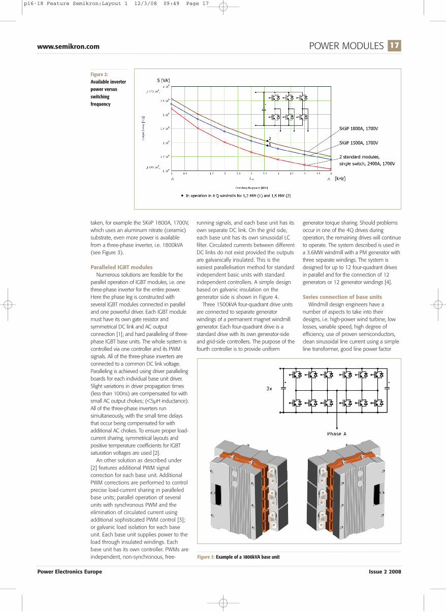
module casings. For comparison, we cantake the largest single-switch module, theIHM 2400A/1700V, and compare twosuch modules with a dual module ofsimilar size and length, SKiiP1513GB172. Ifthe two SKiiPs are put back to back on oneheat sink, a half-bridge is obtained forcurrents 2 x 1500A = 3000A (casetemperature = 25°C), or 2250A for a casetemperature of 70°C. Two single-switchmodules will provide a half-bridge for2400A. If we compare the results of thecalculations, we can see that the SKiiPsolution provides higher output currentsthroughout the complete range ofswitching frequencies than a standardmodule in the largest available case would(see Figure 2).If a more powerful SKiiP module is
Figure 1: Comparison of output power (left) and efficiency of IGBT converters with different blocking voltages at same cooling conditions and Fsw = 3.6kHz;cosφ = 0.9 and same module
p16-18 Feature Semikron:Layout 1 12/3/08 09:49 Page 16
www.semikron.com POWER MODULES 17
Power Electronics Europe Issue 2 2008
taken, for example the SKiiP 1800A, 1700V,which uses an aluminum nitrate (ceramic)substrate, even more power is availablefrom a three-phase inverter, i.e. 1800kVA(see Figure 3).
Paralleled IGBT modulesNumerous solutions are feasible for the
parallel operation of IGBT modules, i.e. onethree-phase inverter for the entire power.Here the phase leg is constructed withseveral IGBT modules connected in paralleland one powerful driver. Each IGBT modulemust have its own gate resistor andsymmetrical DC link and AC outputconnection [1]; and hard paralleling of three-phase IGBT base units. The whole system iscontrolled via one controller and its PWMsignals. All of the three-phase inverters areconnected to a common DC link voltage.Paralleling is achieved using driver parallelingboards for each individual base unit driver.Slight variations in driver propagation times(less than 100ns) are compensated for withsmall AC output chokes; (<5µH inductance).All of the three-phase inverters runsimultaneously, with the small time delaysthat occur being compensated for withadditional AC chokes. To ensure proper load-current sharing, symmetrical layouts andpositive temperature coefficients for IGBTsaturation voltages are used [2].An other solution as described under
[2] features additional PWM signalcorrection for each base unit. AdditionalPWM corrections are performed to controlprecise load-current sharing in paralleledbase units; parallel operation of severalunits with synchronous PWM and theelimination of circulated current usingadditional sophisticated PWM control [3];or galvanic load isolation for each baseunit. Each base unit supplies power to theload through insulated windings. Eachbase unit has its own controller. PWMs areindependent, non-synchronous, free-
running signals, and each base unit has itsown separate DC link. On the grid side,each base unit has its own sinusoidal LCfilter. Circulated currents between differentDC links do not exist provided the outputsare galvanically insulated. This is theeasiest parallelisation method for standardindependent basic units with standardindependent controllers. A simple designbased on galvanic insulation on thegenerator side is shown in Figure 4.Three 1500kVA four-quadrant drive units
are connected to separate generatorwindings of a permanent magnet windmillgenerator. Each four-quadrant drive is astandard drive with its own generator-sideand grid-side controllers. The purpose of thefourth controller is to provide uniform
generator torque sharing. Should problemsoccur in one of the 4Q drives duringoperation, the remaining drives will continueto operate. The system described is used ina 3.6MW windmill with a PM generator withthree separate windings. The system isdesigned for up to 12 four-quadrant drivesin parallel and for the connection of 12generators or 12 generator windings [4].
Series connection of base unitsWindmill design engineers have a
number of aspects to take into theirdesigns, i.e. high-power wind turbine, lowlosses, variable speed, high degree ofefficiency, use of proven semiconductors,clean sinusoidal line current using a simpleline transformer, good line power factor
Figure 2:Available inverterpower versusswitchingfrequency
Figure 3: Example of a 1800kVA base unit
p16-18 Feature Semikron:Layout 1 12/3/08 09:49 Page 17

and low THD, active and reactive powercontrol, modular design to allow for usewith various powers and voltages, quickassembly, high degree of reliability, andlowest possible costs. Best solution is themedium-voltage generator.A medium-voltage generator is a must in
high-power windmill designs of the future.Medium-voltage silicon, however, is notsuitable for such applications. The rightsolution is therefore to connect base unitsin series.An example: a 5MW windmill generator
with 6.3kV rated output voltage has outputcurrents of 3 x 436Arms. The rectifiedvariable speed generator voltage is in therange of 1 to 10kVDC. How can suchvariable voltage be connected to the grid?Each windmill needs to have its own
transformer to allow for connection to thegrid; grid voltage would be in the range of20 to 30kV, which would be thetransformer output voltage. The transformercan be produced with several - in this case10 - three-phase windings, each for 3 x690V, which are used as input voltages.The new medium-voltage windmillprinciple is shown in Figure 5.One base unit, a 600kVA three-phase
inverter, is attached to each three-phasewinding. A fourth IGBT leg can beconnected in front of each base unit. Thisarrangement can be referred to as amedium-voltage cell. All of the cells can beconnected in series, as shown in Figure 7. Ifthe IGBT switch of the fourth leg isswitched-off, the generator DC current willcharge the cell DC-link voltage. The three-phase inverter on the cell-grid sidedischarges, controlling its own DC-linkvoltage. For 3 x 690VAC voltage, the DC-link voltage will be 1050V. Ten base units inseries can produce a Counter ElectroMotive Force (EMF) of up to 10 x1050 =
10.5kV. The voltage remains balanced withthe rectified generator voltage. If thegenerator speed is lower, the generatorvoltage will be lower, too. For this reason, tocontrol the rectified DC current, which inturn means controlling the generatortorque, some of the cells have to bebypassed. If five cells are bypassed, theremaining counter EMF is 5 x 1050 =5.25kV. Bypassing more cells will increasethe DC current and the generator torque.Bypassed cells can deliver full reactivepower to the grid. If one cell is notfunctioning, it will also be bypassed. Themaximum cell DC link voltage is 1200V. Forthis reason, even as few as nine cells inseries can carry the rectified generatorvoltage of up to 9 x 1200V = 10.8kV.
ConclusionHigh-power applications use numerous
IGBT modules. It is far better, however, touse more switches with separate controls,e.g. several units connected in parallel or inseries rather than one large single unit. Theadvantages are as follows: good line power
factor and low current THD with a lowerswitching frequency and fewer passivecomponents, modular design that issuitable for various powers and voltages, aswell as quick assembly, use of provensemiconductor elements, greater efficiency,high degree of reliability, and extremely lowcosts per kW.
References[1] D. Srajber ‘IGBT with
Homogeneous Structure used for HighPower Converter Design’ PCIM 1991Nuremberg Germany[2] SEMIKRON Application Notes
‘SKiiP Parallel Operation of ‘GB’-typeSKiiP Systems’http://www.neu.skd.semikron.com/internet/webcms/objects/pdf/Application_notes_SKiiP_engl.pdf[3] D. Boroyevich: ‘MODELING AND
CONTROL OF PARALLEL THREE-PHASEPWM CONVERTERS’[4] The Switch, www.theswitch.fi[5] United States Patent US 6,680,856
B2
Figure 4: Threeindependent 4Qdrives in parallel withseparate motorwindings, the drivecan operate with oneor two drives inparallel
Figure 5: Cell-based medium-voltage windmill
Issue 2 2008 Power Electronics Europe
POWER MODULES www.semikron.com18
p16-18 Feature Semikron:Layout 1 12/3/08 09:49 Page 18