16 obdg03 ecm summary tables (initial dtcs) · 2017. 9. 19. · 20 failures out of samples25 250 ms...
TRANSCRIPT

Component/System
FaultCode
Monitor Description Malfunction Criteria Threshold Value Secondary Parameters Enable Conditions Time Required MILIllum.
HeaterCoolantPumpControlCircuit Open
B269A Diagnoses the HeaterCoolant Pump low sidedriver circuit for circuitfaults.
Voltage low during driveroff state (indicates opencircuit)
Open Circuit: 200 K impedance
between signal andcontroller ground.
Run Crank Ignition inRange
Engine not cranking
Run Crank active
== Above is true and ==
Last Open Circuit Test
= True
= True
= True
====================
not Indeterminate
failures out of5samples10
1 sec/ sample
Continuous
Type B,2 TripsNote: IncertiancontrollersB269Cmay alsoset
1
16 OBDG03 ECM Summary Tables (Initial DTCs)
ECM (Initial DTCs) Section 1 of 478 1 of 991

Component/System
FaultCode
Monitor Description Malfunction Criteria Threshold Value Secondary Parameters Enable Conditions Time Required MILIllum.
HeaterCoolantPumpControlCircuit Low
B269C Diagnoses the HeaterCoolant Pump low sidedriver circuit for circuitfaults.
Voltage low during driveroff state (indicates short-to-ground)
Short to ground: 0.5 impedance
between signal andcontroller ground
Run Crank Ignition inRange
Engine not cranking
Run Crank active
== Above is true and ==
Last Ground Short CircuitTest
= True
= True
= True
=================
not Indeterminate
failures out of5samples10
1 sec/ sample
Continuous
Type B,2 TripsNote: IncertiancontrollersB269Amay alsoset
2
16 OBDG03 ECM Summary Tables (Initial DTCs)
ECM (Initial DTCs) Section 2 of 478 2 of 991

Component/System
FaultCode
Monitor Description Malfunction Criteria Threshold Value Secondary Parameters Enable Conditions Time Required MILIllum.
HeaterCoolantPumpControlCircuit High
B269D Diagnoses the HeaterCoolant Pump low sidedriver circuit for circuitfaults.
Voltage high during driveron state (indicates shortto power)
Short to power: 0.5 impedance
between signal andcontroller power.
Run Crank Ignition inRange
Engine not cranking
Run Crank active
== Above is true and ==
Last Power Short CircuitTest
= True
= True
= True
=================
not Indeterminate
failures out of5samples10
1 sec/ sample
Continuous
Type B,2 Trips
3
16 OBDG03 ECM Summary Tables (Initial DTCs)
ECM (Initial DTCs) Section 3 of 478 3 of 991

Component/System
FaultCode
Monitor Description Malfunction Criteria Threshold Value Secondary Parameters Enable Conditions Time Required MILIllum.
IntakeCamshaftActuatorSolenoidCircuit Open– Bank 1
P0010 Diagnoses the VVTsystem high side drivercircuit for circuit faults.
The ECM detects thatvoltage is high duringdriver off state (indicatesshort to power or opencircuit)
Short to power: 0.5 impedance
between signal andcontroller power
Open Circuit: 200 K impedance
between signal andcontroller ground
System supply voltage
Output driver iscommanded on
Ignition switch is in crankor run position
> Volts11.00 100failures out of100samples
250 ms /sample,continuous
Type B,2 Trips
4
16 OBDG03 ECM Summary Tables (Initial DTCs)
ECM (Initial DTCs) Section 4 of 478 4 of 991

Component/System
FaultCode
Monitor Description Malfunction Criteria Threshold Value Secondary Parameters Enable Conditions Time Required MILIllum.
IntakeCamshaftSystemPerformance– Bank 1
P0011 Detects a VVT systemerror by comparing thedesired and actual campositions when VVT isactivated
Camshaft position error[absolute value of(desired position - actualposition)] is compared tothresholds to determine ifexcessive
(Intake cam Bank 1)
Cam Position Error >(P0011_CamPosErrorLimIc1) deg
Intake Cam Phsr Enable
System Voltage
Engine Running
Power Take Off (PTO)active
Desired cam position
Desired AND Measuredcam position
Desired cam positionvariation
No Active DTCs
= TRUE
> Volts11.00
= TRUE
= FALSE
> 0 deg
>(P0011_CamPosErrorLimIc1) degAND<( )CalculatedPerfMaxIc1deg
< deg for3.00(P0011_P05CC_StablePositionTimeIc1) seconds
P0010P2088P2089
135.00failures out of150.00samples
100 ms /sample
Type B,2 Trips
5
16 OBDG03 ECM Summary Tables (Initial DTCs)
ECM (Initial DTCs) Section 5 of 478 5 of 991

Component/System
FaultCode
Monitor Description Malfunction Criteria Threshold Value Secondary Parameters Enable Conditions Time Required MILIllum.
ExhaustCamshaftActuatorSolenoidCircuit Open– Bank 1
P0013 Diagnoses the VVTsystem high side drivercircuit for circuit faults.
The ECM detects thatvoltage is high duringdriver off state (indicatesshort to power or opencircuit)
Short to power: 0.5 impedance
between signal andcontroller power
Open Circuit: 200 K impedance
between signal andcontroller ground
System supply voltage
Output driver iscommanded on
Ignition switch is in crankor run position
> Volts11.00 100failures out of100samples
250 ms /sample,continuous
Type B,2 Trips
6
16 OBDG03 ECM Summary Tables (Initial DTCs)
ECM (Initial DTCs) Section 6 of 478 6 of 991

Component/System
FaultCode
Monitor Description Malfunction Criteria Threshold Value Secondary Parameters Enable Conditions Time Required MILIllum.
ExhaustCamshaftSystemPerformance– Bank 1
P0014 Detects a VVT systemerror by comparing thedesired and actual campositions when VVT isactivated
Camshaft position error[absolute value of(desired position - actualposition)] is compared tothresholds to determine ifexcessive
(Exhaust cam Bank 1)
Cam Position Error >(P0014_CamPosErrorLimEc1) deg
Exhaust Cam PhsrEnable
System Voltage
Engine Running
Power Take Off (PTO)active
Desired cam position
Desired AND Measuredcam position
Desired cam positionvariation
No Active DTCs
= TRUE
> Volts11.00
= TRUE
= FALSE
> 0 deg
>(P0014_CamPosErrorLimEc1) degAND<( )CalculatedPerfMaxEc1deg
< deg for3.00(P0014_P05CE_StablePositionTimeEc1) seconds
P0013P2090P2091
135.00failures out of150.00samples
100 ms /sample
Type B,2 Trips
7
16 OBDG03 ECM Summary Tables (Initial DTCs)
ECM (Initial DTCs) Section 7 of 478 7 of 991

Component/System
FaultCode
Monitor Description Malfunction Criteria Threshold Value Secondary Parameters Enable Conditions Time Required MILIllum.
CrankshaftPosition(CKP)-CamshaftPosition(CMP)CorrelationBank 1Sensor A
P0016 Detects cam to crankmisalignment bymonitoring if camsensor pulse for bank 1sensor A occurs duringthe incorrect crankposition
cam sensor pulses4more than -7.9crank degrees before or
crank degrees12.1after nominal positionin one cam revolution.
Crankshaft and camshaftposition signals aresynchronized
Engine is Spinning
Cam phaser is in "parked"position
No Active DTCs:
Time since last executionof diagnostic
CrankSensor_FAP0340, P0341
< seconds1.0
2 failures out of 3tests.
A failed test is 4failures out of 5samples.
There is a delayafter the firstfailed test toallow thecamshaftposition to returnto the parkposition.
This time isdefined by thetable
.
P0016, P0017,P0018, P0019:CamCorrelation OilTemperatureThreshold
One sample percam rotation
Type B,2 Trips
8
16 OBDG03 ECM Summary Tables (Initial DTCs)
ECM (Initial DTCs) Section 8 of 478 8 of 991

Component/System
FaultCode
Monitor Description Malfunction Criteria Threshold Value Secondary Parameters Enable Conditions Time Required MILIllum.
CrankshaftPosition(CKP)-CamshaftPosition(CMP)CorrelationBank 1Sensor B
P0017 Detects cam to crankmisalignment bymonitoring if camsensor pulse for bank 1sensor B occurs duringthe incorrect crankposition
cam sensor pulses4more than -7.9crank degrees before or
crank degrees after12.1nominal position in onecam revolution.
Crankshaft and camshaftposition signals aresynchronized
Engine is Spinning
Cam phaser is in "parked"position
No Active DTCs:
Time since last executionof diagnostic
CrankSensor_FAP0365, P0366
< seconds1.0
2 failures out of 3tests.
A failed test is 4failures out of 5samples.
There is a delayafter the firstfailed test toallow thecamshaftposition to returnto the parkposition.
This time isdefined by thetable
.
P0016, P0017,P0018, P0019:CamCorrelation OilTemperatureThreshold
One sample percam rotation
Type B,2 Trips
9
16 OBDG03 ECM Summary Tables (Initial DTCs)
ECM (Initial DTCs) Section 9 of 478 9 of 991

Component/System
FaultCode
Monitor Description Malfunction Criteria Threshold Value Secondary Parameters Enable Conditions Time Required MILIllum.
O2S HeaterControlCircuit Bank1 Sensor 1
P0030 Diagnoses the HeaterOutput low side drivercircuit for circuit faults.
Voltage low during driveroff state (indicates opencircuit)
Open Circuit:>= 200 K ohmsimpedance betweensignal and controllerground.
IgnitionVoltageEngine Speed
= Crank or Run> volts11.0> RPM400
failures out20of samples25
250 ms / sample
Continuous
Type B,2 TripsNote: Incertaincontrollers P0031may alsoset
10
16 OBDG03 ECM Summary Tables (Initial DTCs)
ECM (Initial DTCs) Section 10 of 478 10 of 991

Component/System
FaultCode
Monitor Description Malfunction Criteria Threshold Value Secondary Parameters Enable Conditions Time Required MILIllum.
O2S HeaterControlCircuitBank1Sensor1
P0031 Diagnoses the HeaterOutput low side drivercircuit for circuit faults.
Voltage low during driveroff state (indicates short-to-ground).
Short to ground:<= 0.5 ohmsimpedance betweensignal and controllerground.
IgnitionVoltageEngine Speed
= Crank or Run> volts11.0> RPM400
failures out20of samples25
250 ms / sample
Continuous
Type B,2 TripsNote: Incertaincontrollers P0030may alsoset
11
16 OBDG03 ECM Summary Tables (Initial DTCs)
ECM (Initial DTCs) Section 11 of 478 11 of 991

Component/System
FaultCode
Monitor Description Malfunction Criteria Threshold Value Secondary Parameters Enable Conditions Time Required MILIllum.
O2S HeaterControlCircuitBank1Sensor1
P0032 Diagnoses the HeaterOutput low side drivercircuit for circuit faults.
Voltage high during driveron state (indicates shortto power).
Short to power:<= 0.5 ohmsimpedance betweensignal and controllerpower.
IgnitionVoltageEngine Speed
= Crank or Run> volts11.0> RPM400
failures out20of samples25
250 ms / sample
Continuous
Type B,2 Trips
12
16 OBDG03 ECM Summary Tables (Initial DTCs)
ECM (Initial DTCs) Section 12 of 478 12 of 991

Component/System
FaultCode
Monitor Description Malfunction Criteria Threshold Value Secondary Parameters Enable Conditions Time Required MILIllum.
Turbo/SuperChargerBypassValveControlCircuit
P0033 Detect TurbochargerBypass Valve - OpenCircuit
ECM detects thatcommanded and actualstates of output driver donot match because theoutput is open circuit
Open circuit:
200 K impedencebetween signal andcontroller ground
Diagnostic Enabled
EnabledPowertrain relayVoltage
Ignition run crank voltage
Engine is not cranking
Diagnostic System notDisabled
True
>= Volts11.0
> Volts5.00
failures out of20samples100
100ms / sample
Type A,1 Trips
Note: Incertaincontrollers P0034may alsoset(Turbo/SuperChargerBypassValveControlCircuitLow)
13
16 OBDG03 ECM Summary Tables (Initial DTCs)
ECM (Initial DTCs) Section 13 of 478 13 of 991

Component/System
FaultCode
Monitor Description Malfunction Criteria Threshold Value Secondary Parameters Enable Conditions Time Required MILIllum.
Turbo/SuperChargerBypassValveControlCircuit Low
P0034 Detect TurbochargerBypass Valve - Shortedto Ground
ECM detects thatcommanded and actualstates of output driver donot match because theoutput is shorted toground
Short to ground:
0.5 impedencebetween signal andcontroller ground
Diagnostic Enabled
EnabledPowertrain relayVoltage
Ignition run crank voltage
Engine is not cranking
Diagnostic System notDisabled
True
>= Volts11.0
> Volts5.00
failures out of20samples100
100ms / sample
Type A,1 Trips
Note: Incertaincontrollers P0033may alsoset(Turbo/SuperChargerBypassValveControlCircuit)
14
16 OBDG03 ECM Summary Tables (Initial DTCs)
ECM (Initial DTCs) Section 14 of 478 14 of 991

Component/System
FaultCode
Monitor Description Malfunction Criteria Threshold Value Secondary Parameters Enable Conditions Time Required MILIllum.
Turbo/SuperChargerBypassValveControlCircuit High
P0035 Detect TurbochargerBypass Valve - Shortedto Power
ECM detects thatcommanded and actualstates of output driver donot match because theoutput is shorted to power
Short to power:
0.5 impedencebetween signal andcontroller power
Diagnostic Enabled
EnabledPowertrain relayVoltage
Ignition run crank voltage
Engine is not cranking
Diagnostic System notDisabled
True
>= Volts11.0
> Volts5.00
failures out of20samples100
100ms / sample
Type A,1 Trips
15
16 OBDG03 ECM Summary Tables (Initial DTCs)
ECM (Initial DTCs) Section 15 of 478 15 of 991

Component/System
FaultCode
Monitor Description Malfunction Criteria Threshold Value Secondary Parameters Enable Conditions Time Required MILIllum.
O2S HeaterControlCircuit Bank1 Sensor 2
P0036 Diagnoses the HeaterOutput low side drivercircuit for circuit faults.
Voltage low during driveroff state (indicates opencircuit).
Open Circuit:>= 200 K ohmsimpedance betweensignal and controllerground.
IgnitionVoltageEngine Speed
= Crank or Run> volts11.0> RPM400
failures out20of samples25
250 ms / sample
Continuous
Type B,2 TripsNote: Incertaincontrollers P0037may alsoset
16
16 OBDG03 ECM Summary Tables (Initial DTCs)
ECM (Initial DTCs) Section 16 of 478 16 of 991
Component/System
FaultCode
Monitor Description Malfunction Criteria Threshold Value Secondary Parameters Enable Conditions Time Required MILIllum.
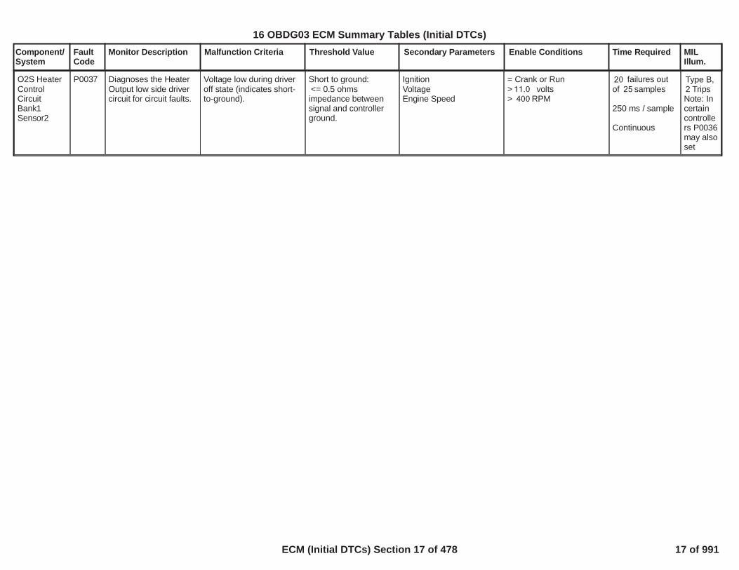
O2S HeaterControlCircuitBank1Sensor2
P0037 Diagnoses the HeaterOutput low side drivercircuit for circuit faults.
Voltage low during driveroff state (indicates short-to-ground).
Short to ground:<= 0.5 ohmsimpedance betweensignal and controllerground.
IgnitionVoltageEngine Speed
= Crank or Run> volts11.0> RPM400
failures out20of samples25
250 ms / sample
Continuous
Type B,2 TripsNote: Incertaincontrollers P0036may alsoset
17
16 OBDG03 ECM Summary Tables (Initial DTCs)
ECM (Initial DTCs) Section 17 of 478 17 of 991

Component/System
FaultCode
Monitor Description Malfunction Criteria Threshold Value Secondary Parameters Enable Conditions Time Required MILIllum.
O2S HeaterControlCircuitBank1Sensor2
P0038 Diagnoses the HeaterOutput low side drivercircuit for circuit faults.
Voltage high during driveron state (indicates shortto power).
Short to power:<= 0.5 ohmsimpedance betweensignal and controllerpower.
IgnitionVoltageEngine Speed
= Crank or Run> volts11.0> RPM400
failures out20of samples25
250 ms / sample
Continuous
Type B,2 Trips
18
16 OBDG03 ECM Summary Tables (Initial DTCs)
ECM (Initial DTCs) Section 18 of 478 18 of 991
Component/System
FaultCode
Monitor Description Malfunction Criteria Threshold Value Secondary Parameters Enable Conditions Time Required MILIllum.
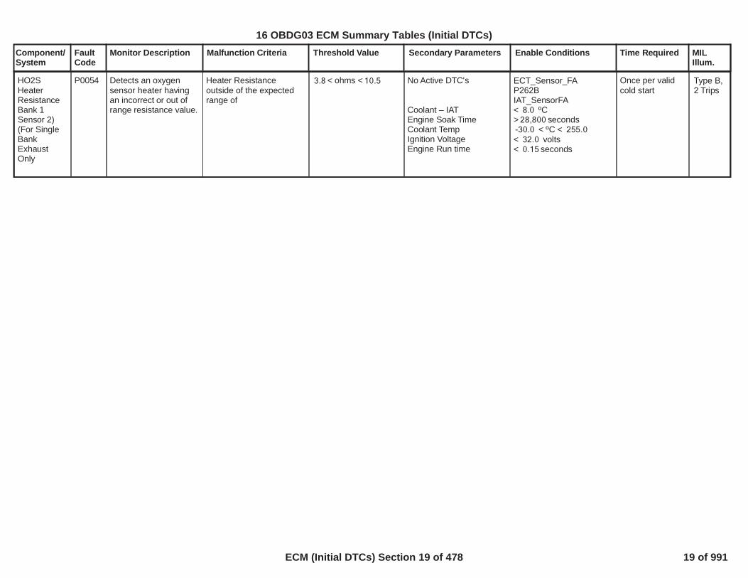
HO2SHeaterResistanceBank 1Sensor 2)(For SingleBankExhaustOnly
P0054 Detects an oxygensensor heater havingan incorrect or out ofrange resistance value.
Heater Resistanceoutside of the expectedrange of
< ohms <3.8 10.5 No Active DTC's
Coolant – IATEngine Soak TimeCoolant TempIgnition VoltageEngine Run time
ECT_Sensor_FAP262BIAT_SensorFA< ºC8.0> seconds28,800
< ºC <-30.0 255.0< volts32.0< seconds0.15
Once per validcold start
Type B,2 Trips
19
16 OBDG03 ECM Summary Tables (Initial DTCs)
ECM (Initial DTCs) Section 19 of 478 19 of 991

Component/System
FaultCode
Monitor Description Malfunction Criteria Threshold Value Secondary Parameters Enable Conditions Time Required MILIllum.
MAP / MAF /ThrottlePositionCorrelation
P0068 Detect when MAP andMAF do not matchestimated engineairflow as establishedby the TPS
Difference between MAPand estimated MAPexceeds threshold (kPa),or P0651 (5 Volt Ref), orP0107 (MAP circuit low),or P0108 (MAP circuithigh) have failed this keycycle, then MAP portion ofdiagnostic fails
Absolute differencebetween MAF andestimated MAF exceedthreshold (grams/sec), orP0102 (MAF circuit low),or P0103 (MAF circuit hi)have failed this key cycle,or maximum MAF versusRPM (Table) is greaterthan or equal to maximumMAF versus batteryvoltage, then MAF portionof diagnostic fails
Table, f(TPS). Seesupporting tables:P0068_Delta MAPThreshold f(TPS)
Table, f(TPS). Seesupporting tables:P0068_Delta MAFThreshold f(TPS)
Table, f(RPM). Seesupporting tables:P0068_MaximumMAF f(RPM)
Table, f(Volts). Seesupporting tables:P0068_MaximumMAF f(Volts)
Engine Speed > RPM800
Run/Crank voltage >6.41
Continuously failMAP and MAFportions ofdiagnostic for
s0.1875
Continuous inMAIN processor
Type A,1 Trips
20
16 OBDG03 ECM Summary Tables (Initial DTCs)
ECM (Initial DTCs) Section 20 of 478 20 of 991
Component/System
FaultCode
Monitor Description Malfunction Criteria Threshold Value Secondary Parameters Enable Conditions Time Required MILIllum.
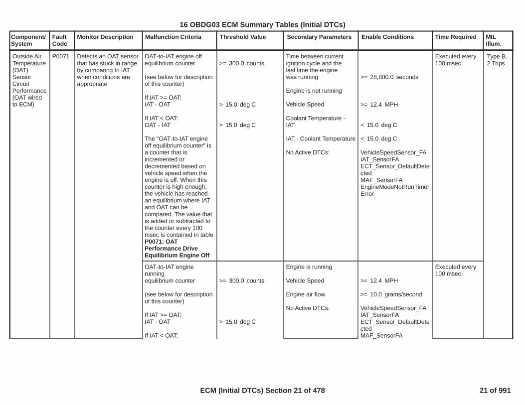
OAT-to-IAT engine offequilibrium counter
(see below for descriptionof this counter)
If IAT >= OAT:IAT - OAT
If IAT < OAT:OAT - IAT
The "OAT-to-IAT engineoff equilibrium counter" isa counter that isincremented ordecremented based onvehicle speed when theengine is off. When thiscounter is high enough,the vehicle has reachedan equilibrium where IATand OAT can becompared. The value thatis added or subtracted tothe counter every 100msec is contained in tableP0071: OATPerformance DriveEquilibrium Engine Off
>= counts300.0
> deg C15.0
> deg C15.0
Time between currentignition cycle and thelast time the enginewas running
Engine is not running
Vehicle Speed
Coolant Temperature -IAT
IAT - Coolant Temperature
No Active DTCs:
>= seconds28,800.0
>= MPH12.4
< deg C15.0
< deg C15.0
VehicleSpeedSensor_FAIAT_SensorFAECT_Sensor_DefaultDetectedMAF_SensorFAEngineModeNotRunTimerError
Executed every100 msec
Outside AirTemperature(OAT)SensorCircuitPerformance(OAT wiredto ECM)
P0071 Detects an OAT sensorthat has stuck in rangeby comparing to IATwhen conditions areappropriate
Type B,2 Trips
OAT-to-IAT enginerunningequilibrium counter
(see below for descriptionof this counter)
If IAT >= OAT:IAT - OAT
If IAT < OAT:
>= counts300.0
> deg C15.0
Engine is running
Vehicle Speed
Engine air flow
No Active DTCs:
>= MPH12.4
>= grams/second10.0
VehicleSpeedSensor_FAIAT_SensorFAECT_Sensor_DefaultDetectedMAF_SensorFA
Executed every100 msec
21
16 OBDG03 ECM Summary Tables (Initial DTCs)
ECM (Initial DTCs) Section 21 of 478 21 of 991

Component/System
FaultCode
Monitor Description Malfunction Criteria Threshold Value Secondary Parameters Enable Conditions Time Required MILIllum.
OAT - IAT
The "OAT-to-IAT enginerunning equilibriumcounter" is a counter thatis incremented ordecremented based onvehicle speed and engineair flow when the engineis running. When thiscounter is high enough,the vehicle has reachedan equilibrium where IATand OAT can becompared. The value thatis added or subtracted tothe counter every 100msec is contained in tableP0071: OATPerformance DriveEquilibrium EngineRunning
> deg C15.0 EngineModeNotRunTimerError
22
16 OBDG03 ECM Summary Tables (Initial DTCs)
ECM (Initial DTCs) Section 22 of 478 22 of 991

Component/System
FaultCode
Monitor Description Malfunction Criteria Threshold Value Secondary Parameters Enable Conditions Time Required MILIllum.
Outside AirTemperature(OAT)SensorCircuit Low
P0072 Detects a continuousshort to ground in theOAT signal circuit orthe OAT sensor
Raw OAT Input <= Ohms52(~150 deg C)
Continuous failures out40of samples50
1 sample every100 msec
Type B,2 Trips
23
16 OBDG03 ECM Summary Tables (Initial DTCs)
ECM (Initial DTCs) Section 23 of 478 23 of 991

Component/System
FaultCode
Monitor Description Malfunction Criteria Threshold Value Secondary Parameters Enable Conditions Time Required MILIllum.
Outside AirTemperature(OAT)SensorCircuit High
P0073 Detects a continuousopen circuit in the OATsignal circuit or theOAT sensor
Raw OAT Input >= Ohms403,672(~-60 deg C)
Continuous failures out40of samples50
1 sample every100 msec
Type B,2 Trips
24
16 OBDG03 ECM Summary Tables (Initial DTCs)
ECM (Initial DTCs) Section 24 of 478 24 of 991

Component/System
FaultCode
Monitor Description Malfunction Criteria Threshold Value Secondary Parameters Enable Conditions Time Required MILIllum.
Outside AirTemperature(OAT)SensorIntermittentIn-Range
P0074 Detects a noisy orerratic OAT signalcircuit or OAT sensor
String Length
Where:
"String Length" = sum of"Diff" calculated over
And where:"Diff" = ABS(current OATreading - OAT readingfrom 100 millisecondsprevious)
> deg C100
consecutive OAT10samples
Continuous failures out of4samples5
Each sampletakes 1.0seconds
Type B,2 Trips
25
16 OBDG03 ECM Summary Tables (Initial DTCs)
ECM (Initial DTCs) Section 25 of 478 25 of 991

Component/System
FaultCode
Monitor Description Malfunction Criteria Threshold Value Secondary Parameters Enable Conditions Time Required MILIllum.
InternalControlModule SIDIHighPressurePump min/maxauthority
P0089 This DTC Diagnosespump control windup toits max or min authority
High Pressure Fuel PumpDelivery Angle
High Pressure Fuel PumpDelivery Angle
>= °101
Or <= °0 Battery Voltage
Low Side Fuel Pressure
Engine Run Time
Barometric PressureInlet Air Temp
Fuel Temp
Additional EnableConditions:All must be true(High Pressure Pump isenabled andHigh Fuel pressuresensor ckt is Not (FA,FPor TFTKO) andHigh Pressure fuel pumpckt is Not (FA,FP orTFTKO) andCam orCrank Sensor Not FA and
High Pressure PumpPerformance DiagnosticEnable
>= Volts11
> MPa0.275
>=P0089 - P163A - P228C -P228D - P0191 -KtFHPD_t_PumpCntrlEngRunThrsh(see supporting tables)
Enabled when a codeclear is not active or notexiting device control
Engine is not cranking
>= KPA70.0>= degC-10.0
<= Temp degC <=-10126
Windup High -
1,000failures out of1,250samples
Windup Low -
1,000failures out of1,250Samples
samples per4engine rotaion
Type B,2 Trips
26
16 OBDG03 ECM Summary Tables (Initial DTCs)
ECM (Initial DTCs) Section 26 of 478 26 of 991

Component/System
FaultCode
Monitor Description Malfunction Criteria Threshold Value Secondary Parameters Enable Conditions Time Required MILIllum.
IAT,IAT2,ECT Not FA andLow side Fuel PumpRelay ckt Not FA andEstimate fuel rail pressureis valid andGreen Engine (Inassembly plant) is notenabled andNot if low fuel conditionandLow side Fuel Pump is onandInjector Flow Test is notactive andDevice controlcommanded pressure isfalse andDevice control pump cktenabled on is false andEngine movementdetected is trueandManufacturers enablecounter is 0)Flex Fuel Sensor Not FAIgnition voltage out ofcorrelation error(P1682)not active
27
16 OBDG03 ECM Summary Tables (Initial DTCs)
ECM (Initial DTCs) Section 27 of 478 27 of 991

Component/System
FaultCode
Monitor Description Malfunction Criteria Threshold Value Secondary Parameters Enable Conditions Time Required MILIllum.
HighPressurePumpControlSolenoidEnable LowSide OpenCircuit
P0090 The DTC Diagnosesthe High PressurePump Control SolenoidEnable Low SideCircuit for circuit faults.
Voltage low during driveroff state indicates opencircuit
Open Circuit:? 200 K ? impedancebetween signal andcontroller ground
Engine Speed
Battery Voltage
>= RPM50
>= Volts11
Not in pump devicecontrolEnabled when a codeclear is not active or notexiting device control
20failures out of40samples
100 ms /sampleContinuous
Type A,1 Trips
28
16 OBDG03 ECM Summary Tables (Initial DTCs)
ECM (Initial DTCs) Section 28 of 478 28 of 991
Component/System
FaultCode
Monitor Description Malfunction Criteria Threshold Value Secondary Parameters Enable Conditions Time Required MILIllum.
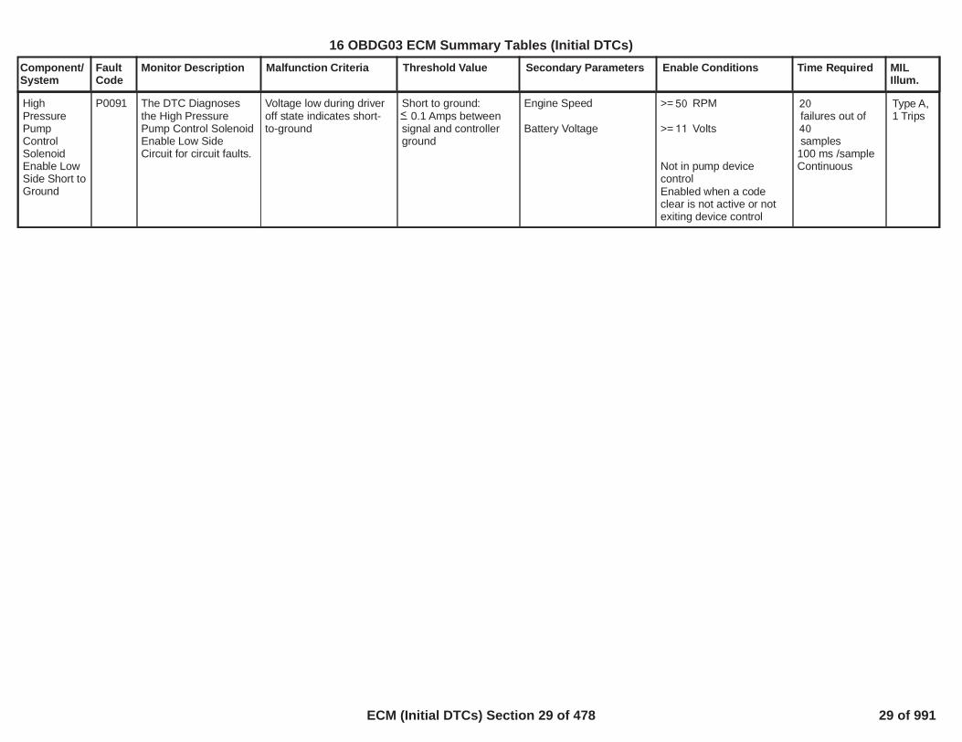
HighPressurePumpControlSolenoidEnable LowSide Short toGround
P0091 The DTC Diagnosesthe High PressurePump Control SolenoidEnable Low SideCircuit for circuit faults.
Voltage low during driveroff state indicates short-to-ground
Short to ground:? 0.1 Amps betweensignal and controllerground
Engine Speed
Battery Voltage
>= RPM50
>= Volts11
Not in pump devicecontrolEnabled when a codeclear is not active or notexiting device control
20failures out of40samples
100 ms /sampleContinuous
Type A,1 Trips
29
16 OBDG03 ECM Summary Tables (Initial DTCs)
ECM (Initial DTCs) Section 29 of 478 29 of 991

Component/System
FaultCode
Monitor Description Malfunction Criteria Threshold Value Secondary Parameters Enable Conditions Time Required MILIllum.
HighPressurePump CntrlSolenoidEnable LowSide Short toPower
P0092 The DTC Diagnosesthe High PressurePump Control SolenoidEnable Low SideCircuit for circuit faults.
Voltage high during driveroff state indicates short topower
Short to power:? 1.1 or 15 Ampsselectable thersholdbased on Highpressure Pump .
Engine Speed
Battery Voltage
>= RPM50>= Volts11
Not in pump devicecontrolEnabled when a codeclear is not active or notexiting device control
20failures out of40samples
100 ms /sampleContinuous
Type A,1 Trips
30
<
16 OBDG03 ECM Summary Tables (Initial DTCs)
ECM (Initial DTCs) Section 30 of 478 30 of 991

Component/System
FaultCode
Monitor Description Malfunction Criteria Threshold Value Secondary Parameters Enable Conditions Time Required MILIllum.
ABS(Power Up IAT -Power Up IAT2)
AND
ABS(Power Up IAT -Power Up IAT3)
AND
ABS(Power Up IAT2 -Power Up IAT3)
> deg C30
<= deg C25
> deg C25
Time between currentignition cycle and the lasttime the engine wasrunning
Powertrain Relay Voltagefor a time
No Active DTCs:
> seconds28,800
>= Volts11.0>= seconds0.9
PowertrainRelayFaultECT_Sensor_Ckt_FAIAT_SensorCircuitFAMnfdTempSensorCktFAHumTempSnsrCktFA
Executes once atthe beginning ofeach ignitioncycle if enableconditions aremet
Intake AirTemperatureSensor 2CircuitPerformance(applicationswith humiditysensor andmanifoldtemperaturesensor)
P0096 Detects an IAT2 sensorthat has stuck in rangeby comparing to IATand IAT3 at startup
Type B,2 Trips
Power Up IAT isbetween Power Up IAT2and Power Up IAT3
AND
ABS(Power Up IAT2 -Power Up IAT3)
AND
ABS(Power Up IAT -Power Up IAT2) >ABS(Power Up IAT -Power Up IAT3)
> deg C25
Time between currentignition cycle and the lasttime the engine wasrunning
Powertrain Relay Voltagefor a time
No Active DTCs:
> seconds28,800
>= Volts11.0>= seconds0.9
PowertrainRelayFaultECT_Sensor_Ckt_FAIAT_SensorCircuitFAMnfdTempSensorCktFAHumTempSnsrCktFA
Executes once atthe beginning ofeach ignitioncycle if enableconditions aremet
Power Up IAT3 isbetween Power Up IATand Power Up IAT2
AND
ABS(Power Up IAT -Power Up IAT2)
AND
ABS(Power Up IAT3 -
> deg C30
Time between currentignition cycle and the lasttime the engine wasrunning
Powertrain Relay Voltagefor a time
No Active DTCs:
> seconds28,800
>= Volts11.0>= seconds0.9
PowertrainRelayFaultECT_Sensor_Ckt_FAIAT_SensorCircuitFAMnfdTempSensorCktFA
Executes once atthe beginning ofeach ignitioncycle if enableconditions aremet
31
16 OBDG03 ECM Summary Tables (Initial DTCs)
ECM (Initial DTCs) Section 31 of 478 31 of 991

Component/System
FaultCode
Monitor Description Malfunction Criteria Threshold Value Secondary Parameters Enable Conditions Time Required MILIllum.
Power Up IAT2) >ABS(Power Up IAT3 -Power Up IAT)
HumTempSnsrCktFA
32
16 OBDG03 ECM Summary Tables (Initial DTCs)
ECM (Initial DTCs) Section 32 of 478 32 of 991

Component/System
FaultCode
Monitor Description Malfunction Criteria Threshold Value Secondary Parameters Enable Conditions Time Required MILIllum.
Intake AirTemperatureSensorCircuit 2 Low(applicationswithhumidity)
P0097 Detects a continuousshort to ground or openin the IAT 2 signalcircuit
Raw IAT 2 Input < Hertz13(~-60 deg C)
Powertrain Relay Voltagefor a time
No Active DTCs:
>= Volts11.0>= seconds0.9
PowertrainRelayFault
failures out40of samples50
1 sample every100 msec
Type B,2 Trips
33
16 OBDG03 ECM Summary Tables (Initial DTCs)
ECM (Initial DTCs) Section 33 of 478 33 of 991

Component/System
FaultCode
Monitor Description Malfunction Criteria Threshold Value Secondary Parameters Enable Conditions Time Required MILIllum.
Intake AirTemperatureSensorCircuit 2High(applicationswithhumidity)
P0098 Detects a continuoushigh frequency in theIAT 2 signal circuit
Raw IAT 2 Input > Hertz390(~150 deg C)
Powertrain Relay Voltagefor a time
No Active DTCs:
>= Volts11.0>= seconds0.9
PowertrainRelayFault
failures out40of samples50
1 sample every100 msec
Type B,2 Trips
34
16 OBDG03 ECM Summary Tables (Initial DTCs)
ECM (Initial DTCs) Section 34 of 478 34 of 991

Component/System
FaultCode
Monitor Description Malfunction Criteria Threshold Value Secondary Parameters Enable Conditions Time Required MILIllum.
Intake AirTemperatureSensor 2IntermittentIn-Range
P0099 Detects a noisy orerratic IAT 2 signalcircuit or IAT 2 sensor
String Length
Where:"String Length" = sum of"Diff" calculated over
And where:"Diff" = ABS(current IAT 2reading - IAT 2 readingfrom 100 millisecondsprevious)
> deg C100.00
consecutive IAT 210samples
Powertrain Relay Voltagefor a time
No Active DTCs:
>= Volts11.0>= seconds0.9
PowertrainRelayFault
failures out of4samples5
Each sampletakes 1.0seconds
Type B,2 Trips
35
16 OBDG03 ECM Summary Tables (Initial DTCs)
ECM (Initial DTCs) Section 35 of 478 35 of 991

Component/System
FaultCode
Monitor Description Malfunction Criteria Threshold Value Secondary Parameters Enable Conditions Time Required MILIllum.
HighPressureStartDiagnostic
P00C6 The DTC Diagnosesthe high side fuelpressure during enginecranking.
The ECM detects that thefuel pressure is not risingor has fallen beyondacceptable limits duringengine cranking
Pressure Rise Test:High Side Fuel Pressure
Pressure Fall Test:High Side Fuel RailPressure
<P00C6 -KtFHPC_p_HighPressStart(see Supporting Table)
<=P00C6 -KtFHPD_p_HPS_PressFallLoThrsh(see Supporting Table)
Low side feed fuelpressure
Engine Run TimeRun/Crank VoltageEngine Coolant
For each engine start,only 1 diagnostic isperformed. The pressurerise test will run if HIghside fuel pressure is lessthanKtFHPC_p_HighPressStart, otherwise, the pressurefall diagnostic will runThe pressure fall runswhen the engine iscranking.
High Pressure FallDiagnostic during StartDisabled
High Pressure RiseDiagnostic during StartEnabled
>= KPA0
< = sec0> Volts8
<= °C <=-100 126
All must be true(High Pressure Pump isenabled andHigh Fuel pressuresensor ckt is Not (FA,FPor TFTKO) andHigh Pressure fuel pumpckt is Not (FA,FP orTFTKO) andCam or Crank Sensor NotFA andIAT, IAT2 and ECT Not FAandLow side Fuel PumpRelay ckt Not FA andEstimate fuel rail pressureis valid andGreen Engine (Inassembly plant) is notenabled andNot if low fuel conditionandLow side Fuel Pump is onandInjector Flow Test is not
Pressure RiseTest:Time >=P00C6 -KtFHPC_t_HighPressStartTmout(see SupportingTable)6.25 ms persample
Pressure FallTest:Injected cylinderevents >=P00C6 -KtFHPD_Cnt_HPS_PressFallLoThrsh(see SupportingTable)
samples per4engine rotation
Type B,2 Trips
36
16 OBDG03 ECM Summary Tables (Initial DTCs)
ECM (Initial DTCs) Section 36 of 478 36 of 991

Component/System
FaultCode
Monitor Description Malfunction Criteria Threshold Value Secondary Parameters Enable Conditions Time Required MILIllum.
Barometric PressureInlet Air Temp
active andDevice controlcommanded pressure isfalse andDevice control pump cktenabled on is false andEngine movementdetected is true andManufacturers enablecounter is 0)Flex Fuel Sensor Not FAIgnition voltage out ofcorrelation error(P1682)not active>= KPA70.0>= DegC-10.0
37
16 OBDG03 ECM Summary Tables (Initial DTCs)
ECM (Initial DTCs) Section 37 of 478 37 of 991

Component/System
FaultCode
Monitor Description Malfunction Criteria Threshold Value Secondary Parameters Enable Conditions Time Required MILIllum.
Intake AirPressureMeasurement System -MultipleSensorCorrelation(single turbo)
P00C7 Detects aninconsistency betweenpressure sensors in theinduction system inwhich a particularsensor cannot beidentified as the failedsensor
ABS(Manifold Pressure -Baro Pressure)ANDABS(Turbocharger BoostPressure - ManifoldPressure)ANDABS(Turbocharger BoostPressure - Baro Pressure)
OR
ABS(Manifold Pressure -Baro Pressure)ANDABS(Turbocharger BoostPressure - ManifoldPressure)ANDABS(Turbocharger BoostPressure - Baro Pressure)
OR
ABS(Manifold Pressure -Baro Pressure)ANDABS(Turbocharger BoostPressure - ManifoldPressure)ANDABS(Turbocharger BoostPressure - Baro Pressure)
OR
ABS(Manifold Pressure -Baro Pressure)ANDABS(Turbocharger BoostPressure - Manifold
> kPa10.0
<= kPa10.0
<= kPa10.0
<= kPa10.0
> kPa10.0
<= kPa10.0
<= kPa10.0
<= kPa10.0
> kPa10.0
> kPa10.0
Time between currentignition cycle and the lasttime the engine wasrunning
Engine is not rotating
Manifold PressureManifold PressureBaro PressureBaro PressureTurbocharger BoostPressureTurbocharger BoostPressure
No Active DTCs:
No Pending DTCs:
> seconds10.0
>= kPa50.0<= kPa115.0>= kPa50.0<= kPa115.0
>= kPa50.0
<= kPa115.0
EngineModeNotRunTimerErrorMAP_SensorFAAAP_SnsrFAAAP2_SnsrFA
MAP_SensorCircuitFPAAP_SnsrCktFPAAP2_SnsrCktFP
failures out of4samples5
1 sample every12.5 msec
Type B,2 Trips
38
16 OBDG03 ECM Summary Tables (Initial DTCs)
ECM (Initial DTCs) Section 38 of 478 38 of 991

Component/System
FaultCode
Monitor Description Malfunction Criteria Threshold Value Secondary Parameters Enable Conditions Time Required MILIllum.
Pressure)ANDABS(Turbocharger BoostPressure - Baro Pressure)
> kPa10.0
> kPa10.0
39
16 OBDG03 ECM Summary Tables (Initial DTCs)
ECM (Initial DTCs) Section 39 of 478 39 of 991
Component/System
FaultCode
Monitor Description Malfunction Criteria Threshold Value Secondary Parameters Enable Conditions Time Required MILIllum.
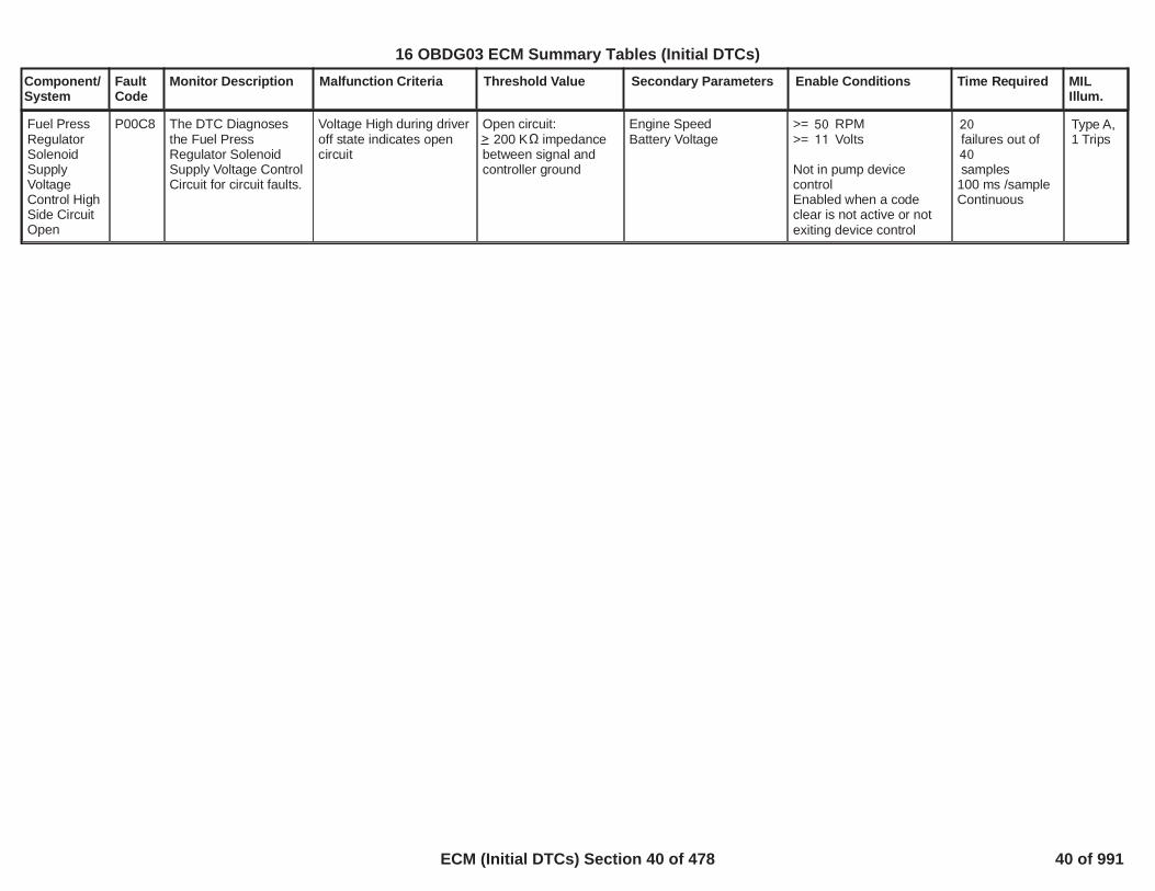
Fuel PressRegulatorSolenoidSupplyVoltageControl HighSide CircuitOpen
P00C8 The DTC Diagnosesthe Fuel PressRegulator SolenoidSupply Voltage ControlCircuit for circuit faults.
Voltage High during driveroff state indicates opencircuit
Open circuit:? 200 K ? impedancebetween signal andcontroller ground
Engine SpeedBattery Voltage
>= RPM50>= Volts11
Not in pump devicecontrolEnabled when a codeclear is not active or notexiting device control
20failures out of40samples
100 ms /sampleContinuous
Type A,1 Trips
40
16 OBDG03 ECM Summary Tables (Initial DTCs)
ECM (Initial DTCs) Section 40 of 478 40 of 991

Component/System
FaultCode
Monitor Description Malfunction Criteria Threshold Value Secondary Parameters Enable Conditions Time Required MILIllum.
Fuel PressRegulatorSolenoidSupplyVoltageControl HighSide CircuitShort toground
P00C9 The DTC Diagnosesthe Fuel PressRegulator SolenoidSupply Voltage ControlCircuit for circuit faults.
Voltage low during driveron state indicates short toground
Short to ground:? 1.1 or 15 Ampsselectable thersholdbased on Highpressure Pump.
Engine SpeedBattery Voltage
>= RPM50>= Volts11
Not in pump devicecontrolEnabled when a codeclear is not active or notexiting device control
20failures out of40samples
100 ms /sampleContinuous
Type A,1 Trips
41
16 OBDG03 ECM Summary Tables (Initial DTCs)
ECM (Initial DTCs) Section 41 of 478 41 of 991

Component/System
FaultCode
Monitor Description Malfunction Criteria Threshold Value Secondary Parameters Enable Conditions Time Required MILIllum.
Fuel PressRegulatorSolenoidSupplyVoltageControl HighSide CircuitShort topower
P00CA The DTC Diagnosesthe Fuel PressRegulator SolenoidSupply Voltage ControlCircuit for circuit faults.
Voltage high during driveroff state indicates short topower
Short to Power:? 0.1 Amps betweensignal and controllerpower
Engine SpeedBattery Voltage
>= RPM50>= Volts11
Not in pump devicecontrolEnabled when a codeclear is not active or notexiting device control
20failures out of40samples
100 ms /sampleContinuous
Type A,1 Trips
42
16 OBDG03 ECM Summary Tables (Initial DTCs)
ECM (Initial DTCs) Section 42 of 478 42 of 991

Component/System
FaultCode
Monitor Description Malfunction Criteria Threshold Value Secondary Parameters Enable Conditions Time Required MILIllum.
ABS(Power Up IAT -Power Up IAT2)
AND
ABS(Power Up IAT -Power Up IAT3)
AND
ABS(Power Up IAT2 -Power Up IAT3)
<= deg C30
> deg C25
> deg C25
Time between currentignition cycle and the lasttime the engine wasrunning
Powertrain Relay Voltagefor a time
No Active DTCs:
> seconds28,800
>= Volts11.0>= seconds0.9
PowertrainRelayFaultECT_Sensor_Ckt_FAIAT_SensorCircuitFAMnfdTempSensorCktFAHumTempSnsrCktFA
Executes once atthe beginning ofeach ignitioncycle if enableconditions aremet
Intake AirTemperatureSensor 3CircuitPerformance(applicationswith humiditysensor andmanifoldtemperaturesensor)
P00E9 Detects an IAT3 sensorthat has stuck in rangeby comparing to IATand IAT2 at startup
Type B,2 Trips
Power Up IAT isbetween Power Up IAT2and Power Up IAT3
AND
ABS(Power Up IAT2 -Power Up IAT3)
AND
ABS(Power Up IAT -Power Up IAT3) >ABS(Power Up IAT -Power Up IAT2)
> deg C25
Time between currentignition cycle and the lasttime the engine wasrunning
Powertrain Relay Voltagefor a time
No Active DTCs:
> seconds28,800
>= Volts11.0>= seconds0.9
PowertrainRelayFaultECT_Sensor_Ckt_FAIAT_SensorCircuitFAMnfdTempSensorCktFAHumTempSnsrCktFA
Executes once atthe beginning ofeach ignitioncycle if enableconditions aremet
Power Up IAT2 isbetween Power Up IATand Power Up IAT3
AND
ABS(Power Up IAT -Power Up IAT3)
AND
ABS(Power Up IAT2 -
> deg C25
Time between currentignition cycle and the lasttime the engine wasrunning
Powertrain Relay Voltagefor a time
No Active DTCs:
> seconds28,800
>= Volts11.0>= seconds0.9
PowertrainRelayFaultECT_Sensor_Ckt_FAIAT_SensorCircuitFAMnfdTempSensorCktFA
Executes once atthe beginning ofeach ignitioncycle if enableconditions aremet
43
16 OBDG03 ECM Summary Tables (Initial DTCs)
ECM (Initial DTCs) Section 43 of 478 43 of 991

Component/System
FaultCode
Monitor Description Malfunction Criteria Threshold Value Secondary Parameters Enable Conditions Time Required MILIllum.
Power Up IAT3) >ABS(Power Up IAT2 -Power Up IAT)
HumTempSnsrCktFA
44
16 OBDG03 ECM Summary Tables (Initial DTCs)
ECM (Initial DTCs) Section 44 of 478 44 of 991

Component/System
FaultCode
Monitor Description Malfunction Criteria Threshold Value Secondary Parameters Enable Conditions Time Required MILIllum.
Intake AirTemperatureSensorCircuit 3 Low(applicationswith manifoldtemperatureandhumidity)
P00EA Detects a continuousshort to ground in theIAT 3 signal circuit orthe IAT 3 sensor
Raw IAT 3 Input < Ohms57(~150 deg C)
Engine Run Time > seconds0.00 failures out40of samples50
1 sample every100 msec
Type B,2 Trips
45
16 OBDG03 ECM Summary Tables (Initial DTCs)
ECM (Initial DTCs) Section 45 of 478 45 of 991
Component/System
FaultCode
Monitor Description Malfunction Criteria Threshold Value Secondary Parameters Enable Conditions Time Required MILIllum.
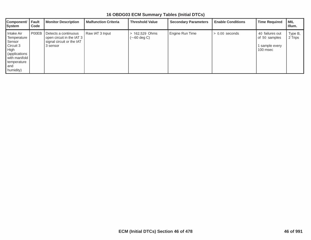
Intake AirTemperatureSensorCircuit 3High(applicationswith manifoldtemperatureandhumidity)
P00EB Detects a continuousopen circuit in the IAT 3signal circuit or the IAT3 sensor
Raw IAT 3 Input > Ohms162,529(~-60 deg C)
Engine Run Time > seconds0.00 failures out40of samples50
1 sample every100 msec
Type B,2 Trips
46
16 OBDG03 ECM Summary Tables (Initial DTCs)
ECM (Initial DTCs) Section 46 of 478 46 of 991

Component/System
FaultCode
Monitor Description Malfunction Criteria Threshold Value Secondary Parameters Enable Conditions Time Required MILIllum.
Intake AirTemperatureSensor 3IntermittentIn-Range
P00EC Detects a noisy orerratic IAT 3 signalcircuit or IAT 3 sensor
String Length
Where:"String Length" = sum of"Diff" calculated over
And where:"Diff" = ABS(current IAT 3reading - IAT 3 readingfrom 100 millisecondsprevious)
> deg C80.00
consecutive IAT 310samples
Continuous failures out of4samples5
Each sampletakes 1.0seconds
Type B,2 Trips
47
16 OBDG03 ECM Summary Tables (Initial DTCs)
ECM (Initial DTCs) Section 47 of 478 47 of 991

Component/System
FaultCode
Monitor Description Malfunction Criteria Threshold Value Secondary Parameters Enable Conditions Time Required MILIllum.
HumiditySensorCircuit Low
P00F4 Detects a continuousshort to power in theHumidity Sensor circuit
Humidity Duty Cycle <= %5.0 Powertrain Relay Voltagefor a time
No Active DTCs:
>= Volts11.0>= seconds0.9
PowertrainRelayFault
failures out40of samples50
1 sample every100 msec
Type B,2 Trips
48
16 OBDG03 ECM Summary Tables (Initial DTCs)
ECM (Initial DTCs) Section 48 of 478 48 of 991

Component/System
FaultCode
Monitor Description Malfunction Criteria Threshold Value Secondary Parameters Enable Conditions Time Required MILIllum.
HumiditySensorCircuit High
P00F5 Detects a continuousopen or short to low inthe Humidity Sensorcircuit
Humidity Duty Cycle >= %95.0 Powertrain Relay Voltagefor a time
No Active DTCs:
>= Volts11.0>= seconds0.9
PowertrainRelayFault
failures out40of samples50
1 sample every100 msec
Type B,2 Trips
49
16 OBDG03 ECM Summary Tables (Initial DTCs)
ECM (Initial DTCs) Section 49 of 478 49 of 991

Component/System
FaultCode
Monitor Description Malfunction Criteria Threshold Value Secondary Parameters Enable Conditions Time Required MILIllum.
HumiditySensorCircuitIntermittent
P00F6 Detects a noisy orerratic humidity sensorinput
String Length
Where:"String Length" = sum of"Diff" calculated over
And where:"Diff" = ABS(currentHumidity reading -Humidity reading from100 millisecondsprevious)
> %80
consecutive10Humidity samples
Powertrain Relay Voltagefor a time
No Active DTCs:
>= Volts11.0>= seconds0.9
PowertrainRelayFault
failures out of4samples5
Each sampletakes 1.0seconds
Type B,2 Trips
50
16 OBDG03 ECM Summary Tables (Initial DTCs)
ECM (Initial DTCs) Section 50 of 478 50 of 991

Component/System
FaultCode
Monitor Description Malfunction Criteria Threshold Value Secondary Parameters Enable Conditions Time Required MILIllum.
Mass AirFlow SystemPerformance(single turbo)
P0101 Determines if the MAFsensor is stuck withinthe normal operatingrange
See tableP0101, P0106, P010B,P0121, P0236, P1101:Turbocharger IntakeFlow RationalityDiagnostic FailureMatrixfor combinationsof model failures that canset this DTC.
MAF model fails whenABS(Measured Flow –Modeled Air Flow) Filtered
MAP1 model fails whenABS(Measured MAP –MAP Model 1) Filtered
MAP2 model fails whenABS(Measured MAP –MAP Model 2) Filtered
MAP3 model fails whenABS(Measured MAP –MAP Model 3) Filtered
TIAP1 model fails whenABS(Measured TIAP –TIAP Model 1) Filtered
TPS model fails whenFiltered Throttle ModelError
TIAP Correlation modelfails whenHigh Engine Air Flow isTRUEAND
> grams/sec20.0
> kPa30.0
> kPa30.0
> kPa30.0
> kPa30.0
> kPa*(g/s)300
Engine SpeedEngine SpeedCoolant TempCoolant TempIntake Air TempIntake Air Temp
Minimum total weightfactor (all factorsmultiplied together)
See Residual WeightFactor tables.
>= RPM400<= RPM6,000> Deg C-7< Deg C130> Deg C-20< Deg C125
>= 0.50
Modeled Air Flow Errormultiplied byP0101, P0106, P010B,P0121, P012B, P0236,P1101: MAF1 ResidualWeight Factor based onRPMandP0101, P0106, P010B,P0121, P012B, P0236,P1101: MAF1 ResidualWeight Factor based onMAF Est
MAP Model 1 Errormultiplied byP0101, P0106, P0121,P012B, P0236, P1101:MAP1 Residual WeightFactor based on RPM
MAP Model 2 Errormultiplied byP0101, P0106, P0121,P012B, P0236, P1101:MAP2 Residual WeightFactor based on RPM
MAP Model 3 Errormultiplied by
Continuous
Calculation areperformed every12.5 msec
Type B,2 Trips
51
16 OBDG03 ECM Summary Tables (Initial DTCs)
ECM (Initial DTCs) Section 51 of 478 51 of 991
Component/System
FaultCode
Monitor Description Malfunction Criteria Threshold Value Secondary Parameters Enable Conditions Time Required MILIllum.
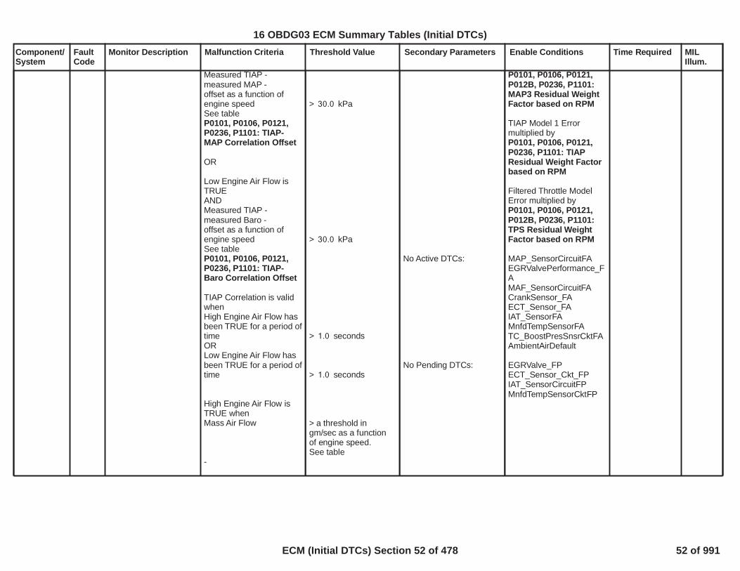
Measured TIAP -measured MAP -offset as a function ofengine speedSee tableP0101, P0106, P0121,P0236, P1101: TIAP-MAP Correlation Offset
OR
Low Engine Air Flow isTRUEANDMeasured TIAP -measured Baro -offset as a function ofengine speedSee tableP0101, P0106, P0121,P0236, P1101: TIAP-Baro Correlation Offset
TIAP Correlation is validwhenHigh Engine Air Flow hasbeen TRUE for a period oftimeORLow Engine Air Flow hasbeen TRUE for a period oftime
High Engine Air Flow isTRUE whenMass Air Flow
-
> kPa30.0
> kPa30.0
> seconds1.0
> seconds1.0
> a threshold ingm/sec as a functionof engine speed.See table
No Active DTCs:
No Pending DTCs:
P0101, P0106, P0121,P012B, P0236, P1101:MAP3 Residual WeightFactor based on RPM
TIAP Model 1 Errormultiplied byP0101, P0106, P0121,P0236, P1101: TIAPResidual Weight Factorbased on RPM
Filtered Throttle ModelError multiplied byP0101, P0106, P0121,P012B, P0236, P1101:TPS Residual WeightFactor based on RPM
MAP_SensorCircuitFAEGRValvePerformance_FAMAF_SensorCircuitFACrankSensor_FAECT_Sensor_FAIAT_SensorFAMnfdTempSensorFATC_BoostPresSnsrCktFAAmbientAirDefault
EGRValve_FPECT_Sensor_Ckt_FPIAT_SensorCircuitFPMnfdTempSensorCktFP
52
16 OBDG03 ECM Summary Tables (Initial DTCs)
ECM (Initial DTCs) Section 52 of 478 52 of 991

Component/System
FaultCode
Monitor Description Malfunction Criteria Threshold Value Secondary Parameters Enable Conditions Time Required MILIllum.
ANDManifold Pressure
ANDFiltered Mass Air Flow -Mass Air Flow
Low Engine Air Flow isTRUE whenMass Air Flow
ANDManifold Pressure
ANDMass Air Flow - FilteredMass Air Flow
P0101, P0106, P0121,P0236, P1101: TIAP-MAP Correlation MinAir Flow
> a threshold in kPaas a function ofengine speed.See tableP0101, P0106, P0121,P0236, P1101: TIAP-MAP Correlation MinMAP
< gm/sec3.0
< a threshold ingm/sec as a functionof engine speed.See tableP0101, P0106, P0121,P0236, P1101: TIAP-Baro Correlation MaxAir Flow
< a threshold in kPa asa function of enginespeed. See tableP0101, P0106, P0121,P0236, P1101: TIAP-Baro Correlation MaxMAP
< gm/sec2.0
53
16 OBDG03 ECM Summary Tables (Initial DTCs)
ECM (Initial DTCs) Section 53 of 478 53 of 991

Component/System
FaultCode
Monitor Description Malfunction Criteria Threshold Value Secondary Parameters Enable Conditions Time Required MILIllum.
Mass AirFlow SensorCircuit LowFrequency
P0102 Detects a continuousshort to low or a openin either the signalcircuit or the MAFsensor
MAF Output <= Hertz750(~ gm/sec)0.34
Engine Run TimeEngine SpeedIgnition VoltageAbove criteria present fora period of time
> seconds1.0>= RPM300>= Volts11.0
>= seconds1.0
failures out200of samples250
1 sample everycylinder firingevent
Type B,2 Trips
54
16 OBDG03 ECM Summary Tables (Initial DTCs)
ECM (Initial DTCs) Section 54 of 478 54 of 991

Component/System
FaultCode
Monitor Description Malfunction Criteria Threshold Value Secondary Parameters Enable Conditions Time Required MILIllum.
Mass AirFlow SensorCircuit HighFrequency
P0103 Detects a highfrequency output fromthe MAF sensor
MAF Output >= Hertz13,350(~ gm/sec)489.9
Engine Run TimeEngine SpeedIgnition VoltageAbove criteria present fora period of time
> seconds1.0>= RPM300>= Volts11.0
>= seconds1.0
failures out200of samples250
1 sample everycylinder firingevent
Type B,2 Trips
55
16 OBDG03 ECM Summary Tables (Initial DTCs)
ECM (Initial DTCs) Section 55 of 478 55 of 991

Component/System
FaultCode
Monitor Description Malfunction Criteria Threshold Value Secondary Parameters Enable Conditions Time Required MILIllum.
See tableP0101, P0106, P010B,P0121, P0236, P1101:Turbocharger IntakeFlow RationalityDiagnostic FailureMatrixfor combinationsof model failures that canset this DTC.
MAF model fails whenABS(Measured Flow –Modeled Air Flow) Filtered
MAP1 model fails whenABS(Measured MAP –MAP Model 1) Filtered
MAP2 model fails whenABS(Measured MAP –MAP Model 2) Filtered
MAP3 model fails whenABS(Measured MAP –MAP Model 3) Filtered
TIAP1 model fails whenABS(Measured TIAP –TIAP Model 1) Filtered
TPS model fails whenFiltered Throttle ModelError
TIAP Correlation modelfails when
High Engine Air Flow isTRUEANDMeasured TIAP -
> grams/sec20.0
> kPa30.0
> kPa30.0
> kPa30.0
> kPa30.0
> kPa*(g/s)300
Engine SpeedEngine SpeedCoolant TempCoolant TempIntake Air TempIntake Air Temp
Minimum total weightfactor (all factorsmultiplied together)
See Residual WeightFactor tables.
-
>= RPM400<= RPM6,000> Deg C-7< Deg C130> Deg C-20< Deg C125
>= 0.50
Modeled Air Flow Errormultiplied byP0101, P0106, P010B,P0121, P012B, P0236,P1101: MAF1 ResidualWeight Factor based onRPMandP0101, P0106, P010B,P0121, P012B, P0236,P1101: MAF1 ResidualWeight Factor based onMAF Est
MAP Model 1 Errormultiplied byP0101, P0106, P0121,P012B, P0236, P1101:MAP1 Residual WeightFactor based on RPM
MAP Model 2 Errormultiplied byP0101, P0106, P0121,P012B, P0236, P1101:MAP2 Residual WeightFactor based on RPM
MAP Model 3 Errormultiplied by
Continuous
Calculation areperformed every12.5 msec
ManifoldAbsolutePressureSensorPerformance(single turbo)
P0106 Determines if the MAPsensor is stuck withinthe normal operatingrange
Type B,2 Trips
16 OBDG03 ECM Summary Tables (Initial DTCs)
ECM (Initial DTCs) Section 56 of 478 56 of 991

Component/System
FaultCode
Monitor Description Malfunction Criteria Threshold Value Secondary Parameters Enable Conditions Time Required MILIllum.
measured MAP -offset as a function ofengine speedSee tableP0101, P0106, P0121,P0236, P1101: TIAP-MAP Correlation Offset
OR
Low Engine Air Flow isTRUEANDMeasured TIAP -measured Baro -offset as a function ofengine speedSee tableP0101, P0106, P0121,P0236, P1101: TIAP-Baro Correlation Offset
TIAP Correlation is validwhen
High Engine Air Flow hasbeen TRUE for a period oftimeORLow Engine Air Flow hasbeen TRUE for a period oftime
High Engine Air Flow isTRUE whenMass Air Flow
-
> kPa30.0
> kPa30.0
> seconds1.0
> seconds1.0
> a threshold ingm/sec as a functionof engine speedSee table
No Active DTCs:
No Pending DTCs:
P0101, P0106, P0121,P012B, P0236, P1101:MAP3 Residual WeightFactor based on RPM
TIAP Model 1 Errormultiplied byP0101, P0106, P0121,P0236, P1101: TIAPResidual Weight Factorbased on RPM
Filtered Throttle ModelError multiplied byP0101, P0106, P0121,P012B, P0236, P1101:TPS Residual WeightFactor based on RPM
MAP_SensorCircuitFAEGRValvePerformance_FAMAF_SensorCircuitFACrankSensor_FAECT_Sensor_FAIAT_SensorFAMnfdTempSensorFATC_BoostPresSnsrCktFAAmbientAirDefault
EGRValve_FPECT_Sensor_Ckt_FPIAT_SensorCircuitFPMnfdTempSensorCktFP
16 OBDG03 ECM Summary Tables (Initial DTCs)
ECM (Initial DTCs) Section 57 of 478 57 of 991

Component/System
FaultCode
Monitor Description Malfunction Criteria Threshold Value Secondary Parameters Enable Conditions Time Required MILIllum.
ANDManifold Pressure
ANDFiltered Mass Air Flow -Mass Air Flow
Low Engine Air Flow isTRUE whenMass Air Flow
ANDManifold Pressure
ANDMass Air Flow - FilteredMass Air Flow
P0101, P0106, P0121,P0236, P1101: TIAP-MAP Correlation MinAir Flow
> a threshold in kPaas a function ofengine speedSee tableP0101, P0106, P0121,P0236, P1101: TIAP-MAP Correlation MinMAP
< gm/sec3.0
< a threshold ingm/sec as a functionof engine speedSee tableP0101, P0106, P0121,P0236, P1101: TIAP-Baro Correlation MaxAir Flow
< a threshold in kPaas a function ofengine speedSee tableP0101, P0106, P0121,P0236, P1101: TIAP-Baro Correlation MaxMAP
< gm/sec2.0
Manifold PressureORManifold Pressure
< kPa50.0
> kPa115.0
Time between currentignition cycle and the lasttime the engine was
failures out of4samples5
16 OBDG03 ECM Summary Tables (Initial DTCs)
ECM (Initial DTCs) Section 58 of 478 58 of 991

Component/System
FaultCode
Monitor Description Malfunction Criteria Threshold Value Secondary Parameters Enable Conditions Time Required MILIllum.
OR
ABS(Manifold Pressure -Baro Pressure)ANDABS(Turbocharger BoostPressure - ManifoldPressure)ANDABS(Turbocharger BoostPressure - Baro Pressure)
> kPa10.0
> kPa10.0
<= kPa10.0
running
Engine is not rotating
No Active DTCs:
No Pending DTCs:
> seconds10.0
EngineModeNotRunTimerErrorMAP_SensorCircuitFAAAP_SnsrCktFAAAP2_SnsrCktFA
MAP_SensorCircuitFPAAP_SnsrCktFPAAP2_SnsrCktFP
1 sample every12.5 msec
16 OBDG03 ECM Summary Tables (Initial DTCs)
ECM (Initial DTCs) Section 59 of 478 59 of 991

Component/System
FaultCode
Monitor Description Malfunction Criteria Threshold Value Secondary Parameters Enable Conditions Time Required MILIllum.
ManifoldAbsolutePressureSensorCircuit Low(Gen III)
P0107 Detects a continuousshort to low in eitherthe signal circuit or theMAP sensor.
MAP Voltage < % of 5 Volt9.0Range(This is equal to 0.45Volts or kPa)5.8
Continuous failures out320of samples400
1 sample every12.5 msec
Type B,2 Trips
60
16 OBDG03 ECM Summary Tables (Initial DTCs)
ECM (Initial DTCs) Section 60 of 478 60 of 991

Component/System
FaultCode
Monitor Description Malfunction Criteria Threshold Value Secondary Parameters Enable Conditions Time Required MILIllum.
ManifoldAbsolutePressureSensorCircuit High(Gen III)
P0108 Detects an opensensor ground,continuous short tohigh, or open in eitherthe signal circuit or theMAP sensor.
MAP Voltage > % of 5 Volt78.0Range(This is equal to 3.90Volts, or kPa)299.0
Continuous failures out320of samples400
1 sample every12.5 msec
Type B,2 Trips
61
16 OBDG03 ECM Summary Tables (Initial DTCs)
ECM (Initial DTCs) Section 61 of 478 61 of 991
Component/System
FaultCode
Monitor Description Malfunction Criteria Threshold Value Secondary Parameters Enable Conditions Time Required MILIllum.
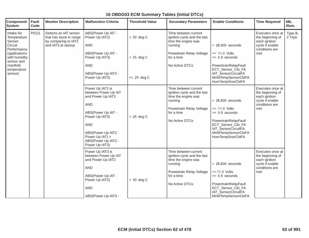
ABS(Power Up IAT -Power Up IAT2)
AND
ABS(Power Up IAT -Power Up IAT3)
AND
ABS(Power Up IAT2 -Power Up IAT3)
> deg C30
> deg C25
<= deg C25
Time between currentignition cycle and the lasttime the engine wasrunning
Powertrain Relay Voltagefor a time
No Active DTCs:
> seconds28,800
>= Volts11.0>= seconds0.9
PowertrainRelayFaultECT_Sensor_Ckt_FAIAT_SensorCircuitFAMnfdTempSensorCktFAHumTempSnsrCktFA
Executes once atthe beginning ofeach ignitioncycle if enableconditions aremet
Intake AirTemperatureSensorCircuitPerformance(applicationswith humiditysensor andmanifoldtemperaturesensor)
P0111 Detects an IAT sensorthat has stuck in rangeby comparing to IAT2and IAT3 at startup
Type B,2 Trips
Power Up IAT2 isbetween Power Up IATand Power Up IAT3
AND
ABS(Power Up IAT -Power Up IAT3)
AND
ABS(Power Up IAT2 -Power Up IAT) >ABS(Power Up IAT2 -Power Up IAT3)
> deg C25
Time between currentignition cycle and the lasttime the engine wasrunning
Powertrain Relay Voltagefor a time
No Active DTCs:
> seconds28,800
>= Volts11.0>= seconds0.9
PowertrainRelayFaultECT_Sensor_Ckt_FAIAT_SensorCircuitFAMnfdTempSensorCktFAHumTempSnsrCktFA
Executes once atthe beginning ofeach ignitioncycle if enableconditions aremet
Power Up IAT3 isbetween Power Up IATand Power Up IAT2
AND
ABS(Power Up IAT -Power Up IAT2)
AND
ABS(Power Up IAT3 -
> deg C30
Time between currentignition cycle and the lasttime the engine wasrunning
Powertrain Relay Voltagefor a time
No Active DTCs:
> seconds28,800
>= Volts11.0>= seconds0.9
PowertrainRelayFaultECT_Sensor_Ckt_FAIAT_SensorCircuitFAMnfdTempSensorCktFA
Executes once atthe beginning ofeach ignitioncycle if enableconditions aremet
62
16 OBDG03 ECM Summary Tables (Initial DTCs)
ECM (Initial DTCs) Section 62 of 478 62 of 991

Component/System
FaultCode
Monitor Description Malfunction Criteria Threshold Value Secondary Parameters Enable Conditions Time Required MILIllum.
Power Up IAT) >ABS(Power Up IAT3 -Power Up IAT2)
HumTempSnsrCktFA
63
16 OBDG03 ECM Summary Tables (Initial DTCs)
ECM (Initial DTCs) Section 63 of 478 63 of 991

Component/System
FaultCode
Monitor Description Malfunction Criteria Threshold Value Secondary Parameters Enable Conditions Time Required MILIllum.
Intake AirTemperatureSensorCircuit Low
P0112 Detects a continuousshort to ground in theIAT signal circuit or theIAT sensor
Raw IAT Input < Ohms58(~150 deg C)
Engine Run Time > seconds0.00 failures out40of samples50
1 sample every100 msec
Type B,2 Trips
64
16 OBDG03 ECM Summary Tables (Initial DTCs)
ECM (Initial DTCs) Section 64 of 478 64 of 991

Component/System
FaultCode
Monitor Description Malfunction Criteria Threshold Value Secondary Parameters Enable Conditions Time Required MILIllum.
Intake AirTemperatureSensorCircuit High
P0113 Detects a continuousopen circuit in the IATsignal circuit or the IATsensor
Raw IAT Input > Ohms142,438(~-60 deg C)
Engine Run Time > seconds0.00 failures out40of samples50
1 sample every100 msec
Type B,2 Trips
65
16 OBDG03 ECM Summary Tables (Initial DTCs)
ECM (Initial DTCs) Section 65 of 478 65 of 991

Component/System
FaultCode
Monitor Description Malfunction Criteria Threshold Value Secondary Parameters Enable Conditions Time Required MILIllum.
Intake AirTemperatureSensorIntermittentIn-Range
P0114 Detects a noisy orerratic IAT signal circuitor IAT sensor
String Length
Where:"String Length" = sum of"Diff" calculated over
And where:"Diff" = ABS(current IATreading - IAT readingfrom 100 millisecondsprevious)
> deg C80.00
consecutive IAT10samples
Continuous failures out of4samples5
Each sampletakes 1.0seconds
Type B,2 Trips
66
16 OBDG03 ECM Summary Tables (Initial DTCs)
ECM (Initial DTCs) Section 66 of 478 66 of 991

Component/System
FaultCode
Monitor Description Malfunction Criteria Threshold Value Secondary Parameters Enable Conditions Time Required MILIllum.
EngineCoolantTemperature(ECT)SensorPerformance
P0116 This DTC detects ECTtemp sensor stuck inmid range.
A failure will be reported ifany of the following occur:
1) ECT at power up > IATat power up by an IATbased table lookup valueafter a minimum25,200second soak (fast fail).
2) ECT at power up > IATat power up by15.8C after a minimum25,200second soak and a blockheater has not beendetected.
3) ECT at power up > IATat power up by C15.8after a minimum 25,200seconds soak and the
time spent cranking theengine without starting isgreater than seconds10.0with theLowFuelConditionDiag
SeeP0116_Fail if powerup ECT exceeds IATby these valuesin the Supportingtables section
= False
No Active DTC's
Non-volatile memoryinitization
Test complete this tripTest aborted this tripIATLowFuelConditionDiag
==================Block Heater detection isenabled when either ofthe following occurs:
1) ECT at power up > IATat power up by
2) Cranking time
==================Block Heater is detectedand diagnostic is abortedwhen 1) or 2) occurs:
1a) Vehicle drive time
1b) Vehicle speed
1c) Additional Vehicledrive time is provided to1a when Vehicle speed isbelow 1b as follows:
VehicleSpeedSensor_FAIAT_SensorFAECT_Sensor_Ckt_FAIgnitionOffTimeValidTimeSinceEngineRunningValid
= Not occurred
= False= False
ºC-7
= False
==================
> ºC15.8
< seconds10.0
==================
> seconds400
with > MPH14.9
times the seconds0.50with vehicle speed below1b
1 failure
500 msec/sample
Once per validcold start
Type B,2 Trips
67
16 OBDG03 ECM Summary Tables (Initial DTCs)
ECM (Initial DTCs) Section 67 of 478 67 of 991
Component/System
FaultCode
Monitor Description Malfunction Criteria Threshold Value Secondary Parameters Enable Conditions Time Required MILIllum.
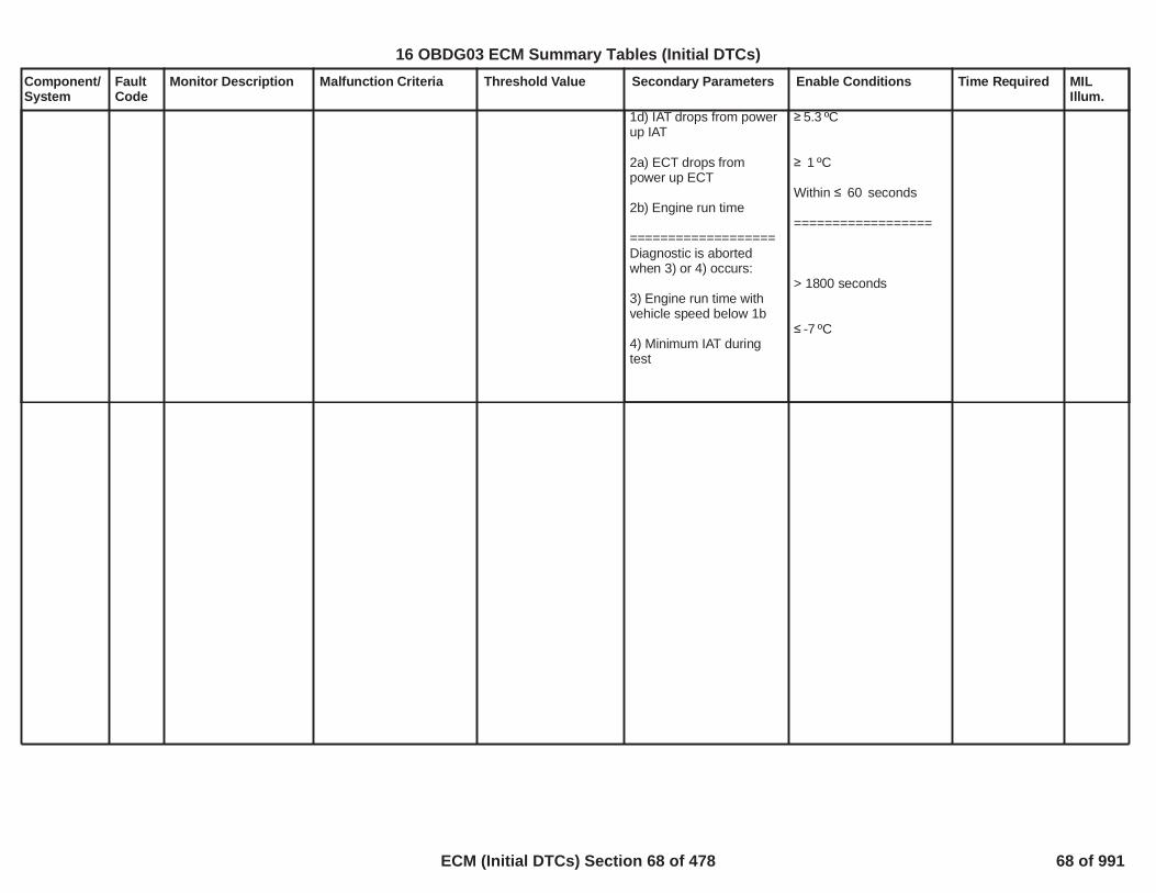
1d) IAT drops from powerup IAT
2a) ECT drops frompower up ECT
2b) Engine run time
===================Diagnostic is abortedwhen 3) or 4) occurs:
3) Engine run time withvehicle speed below 1b
4) Minimum IAT duringtest
ºC5.3
ºC1
Within seconds60
==================
> 1800 seconds
ºC-7
68
16 OBDG03 ECM Summary Tables (Initial DTCs)
ECM (Initial DTCs) Section 68 of 478 68 of 991

Component/System
FaultCode
Monitor Description Malfunction Criteria Threshold Value Secondary Parameters Enable Conditions Time Required MILIllum.
EngineCoolantTempSensorCircuit Low
P0117 Circuit ContinuityThis DTC detects ashort to ground in theECT signal circuit orthe ECT sensor.
ECT Resistance (@150ºC)
< Ohms42 failures out of5samples6
1 sec/ sample
Continuous
Type B,2 Trips
69
16 OBDG03 ECM Summary Tables (Initial DTCs)
ECM (Initial DTCs) Section 69 of 478 69 of 991

Component/System
FaultCode
Monitor Description Malfunction Criteria Threshold Value Secondary Parameters Enable Conditions Time Required MILIllum.
EngineCoolantTempSensorCircuit High
P0118 Circuit ContinuityThis DTC detects ashort to high or open inthe ECT signal circuitor the ECT sensor.
ECT Resistance (@-60ºC)
> Ohms320,000 Engine run timeORIAT min
> seconds10.0
°C-7.0
failures out of5samples6
1 sec/ sample
Continuous
Type B,2 Trips
70
16 OBDG03 ECM Summary Tables (Initial DTCs)
ECM (Initial DTCs) Section 70 of 478 70 of 991

Component/System
FaultCode
Monitor Description Malfunction Criteria Threshold Value Secondary Parameters Enable Conditions Time Required MILIllum.
EngineCoolantTemperature(ECT)SensorCircuitIntermittent
P0119 Circuit ContinuityThis DTC detects largestep changes in theECT signal circuit orthe ECT sensor.Allowable high and lowlimits are calculated forthe next sample basedon the previoussample.
ECT temperature stepchange:
1) postive step change isgreater than calculatedhigh limit
OR
2) negitive step change islower than calculated lowlimit.
The calculated high andlow limits for the nextreading use the followingcalibrations:1) Sensor time constant2) Sensor low limit3) Sensor high limit
*****Generic Example*****
If the last ECT readingwas 90 Deg C, the Timeconstant was calibrated at10 seconds, the low limitwas calibrated to -80 DegC and the high limit wascalibrated to 200 Deg Cthe caluculated limits are101 Deg C and 73 Deg C.
The next reading (afterthe 90 Deg C reading)must be between 73 DegC and 101 Deg C to bevalid.
seconds10.0Deg C-80.0Deg C200.0
No Active DTC's ECT_Sensor_Ckt_FP failures out of3samples4
1 sec/ sample
Continuous
Type B,2 Trips
71
16 OBDG03 ECM Summary Tables (Initial DTCs)
ECM (Initial DTCs) Section 71 of 478 71 of 991

Component/System
FaultCode
Monitor Description Malfunction Criteria Threshold Value Secondary Parameters Enable Conditions Time Required MILIllum.
ThrottlePositionSensorPerformance(single turbo)
P0121 Determines if theThrottle PositionSensor input is stuckwithin the normaloperating range
See tableP0101, P0106, P010B,P0121, P0236, P1101:Turbocharger IntakeFlow RationalityDiagnostic FailureMatrixfor combinations of modelfailures that can set thisDTC.
MAF model fails whenABS(Measured Flow –Modeled Air Flow) Filtered
MAP1 model fails whenABS(Measured MAP –MAP Model 1) Filtered
MAP2 model fails whenABS(Measured MAP –MAP Model 2) Filtered
MAP3 model fails whenABS(Measured MAP –MAP Model 3) Filtered
TIAP1 model fails whenABS(Measured TIAP –TIAP Model 1) Filtered
TPS model fails whenFiltered Throttle ModelError
TIAP Correlation modelfails when
High Engine Air Flow isTRUE ANDMeasured TIAP -
> grams/sec20.0
> kPa30.0
> kPa30.0
> kPa30.0
> kPa30.0
> kPa*(g/s)300
Engine SpeedEngine SpeedCoolant TempCoolant TempIntake Air TempIntake Air Temp
Minimum total weightfactor (all factorsmultiplied together)
See Residual WeightFactor tables.
>= RPM400<= RPM6,000> Deg C-7< Deg C130> Deg C-20< Deg C125
>= 0.50
Modeled Air Flow Errormultiplied byP0101, P0106, P010B,P0121, P012B, P0236,P1101: MAF1 ResidualWeight Factor based onRPMandP0101, P0106, P010B,P0121, P012B, P0236,P1101: MAF1 ResidualWeight Factor based onMAF Est
MAP Model 1 Errormultiplied byP0101, P0106, P0121,P012B, P0236, P1101:MAP1 Residual WeightFactor based on RPM
MAP Model 2 Errormultiplied byP0101, P0106, P0121,P012B, P0236, P1101:MAP2 Residual WeightFactor based on RPM
MAP Model 3 Errormultiplied by
Continuous
Calculation areperformed every12.5 msec
Type B,2 Trips
73
16 OBDG03 ECM Summary Tables (Initial DTCs)
ECM (Initial DTCs) Section 72 of 478 72 of 991

Component/System
FaultCode
Monitor Description Malfunction Criteria Threshold Value Secondary Parameters Enable Conditions Time Required MILIllum.
measured MAP - offset asa function of enginespeedSee tableP0101, P0106, P0121,P0236, P1101: TIAP-MAP Correlation Offset
OR
Low Engine Air Flow isTRUE ANDMeasured TIAP -measured Baro - offset asa function of enginespeedSee tableP0101, P0106, P0121,P0236, P1101: TIAP-Baro Correlation Offset
TIAP Correlation is validwhenHigh Engine Air Flow hasbeen TRUE for a period oftimeORLow Engine Air Flow hasbeen TRUE for a period oftime
High Engine Air Flow isTRUE whenMass Air Flow
AND
> kPa30.0
> kPa30.0
> seconds1.0
> seconds1.0
> a threshold in gmsec as a function ofengine speedSee tableP0101, P0106, P0121,P0236, P1101: TIAP-MAP Correlation MinAir Flow
No Active DTCs:
No Pending DTCs:
P0101, P0106, P0121,P012B, P0236, P1101:MAP3 Residual WeightFactor based on RPM
TIAP Model 1 Errormultiplied byP0101, P0106, P0121,P0236, P1101: TIAPResidual Weight Factorbased on RPM
Filtered Throttle ModelError multiplied byP0101, P0106, P0121,P012B, P0236, P1101:TPS Residual WeightFactor based on RPM
MAP_SensorCircuitFAEGRValvePerformance_FAMAF_SensorCircuitFACrankSensor_FAECT_Sensor_FAIAT_SensorFAMnfdTempSensorFATC_BoostPresSnsrCktFAAmbientAirDefault
EGRValve_FPECT_Sensor_Ckt_FPIAT_SensorCircuitFPMnfdTempSensorCktFP
74
16 OBDG03 ECM Summary Tables (Initial DTCs)
ECM (Initial DTCs) Section 73 of 478 73 of 991

Component/System
FaultCode
Monitor Description Malfunction Criteria Threshold Value Secondary Parameters Enable Conditions Time Required MILIllum.
Manifold Pressure
ANDFiltered Mass Air Flow -Mass Air Flow
Low Engine Air Flow isTRUE whenMass Air Flow
ANDManifold Pressure
ANDMass Air Flow - FilteredMass Air Flow
> a threshold in kPa asa function of enginespeedSee tableP0101, P0106, P0121,P0236, P1101: TIAP-MAP Correlation MinMAP
< gm/sec3.0
< a threshold in gmsec as a function ofengine speedSee tableP0101, P0106, P0121,P0236, P1101: TIAP-Baro Correlation MaxAir Flow
< a threshold in kPa asa function of enginespeedSee tableP0101, P0106, P0121,P0236, P1101: TIAP-Baro Correlation MaxMAP
< gm/sec2.0
75
16 OBDG03 ECM Summary Tables (Initial DTCs)
ECM (Initial DTCs) Section 74 of 478 74 of 991

Component/System
FaultCode
Monitor Description Malfunction Criteria Threshold Value Secondary Parameters Enable Conditions Time Required MILIllum.
TPS1 CircuitLow
P0122 Detects a continuous orintermittent short oropen in TPS1 circuit
TPS1 Voltage < 0.3250 Run/Crank voltage >6.41
No 5V reference error orfault for # 4 5V referencecircuit (P06A3)
/79 159counts;
counts57continuous;3.125 ms /countin the ECM mainprocessor
Type A,1 Trips
76
16 OBDG03 ECM Summary Tables (Initial DTCs)
ECM (Initial DTCs) Section 75 of 478 75 of 991

Component/System
FaultCode
Monitor Description Malfunction Criteria Threshold Value Secondary Parameters Enable Conditions Time Required MILIllum.
TPS1 CircuitHigh
P0123 Detects a continuous orintermittent short oropen in TPS1 circuit
TPS1 Voltage > 4.750 Run/Crank voltage >6.41
No 5V reference error orfault for # 4 5V referencecircuit (P06A3)
/79 159counts;
counts57continuous;3.125 ms /countin the ECM mainprocessor
Type A,1 Trips
77
16 OBDG03 ECM Summary Tables (Initial DTCs)
ECM (Initial DTCs) Section 76 of 478 76 of 991

Component/System
FaultCode
Monitor Description Malfunction Criteria Threshold Value Secondary Parameters Enable Conditions Time Required MILIllum.
EngineCoolantTemperatureBelow StatRegulatingTemperature) (energybased"Deluxe"method
P0128 This DTC detects if theengine coolanttemperature rises tooslowly due to an ECTor Cooling system fault
Energy is accumulatedafter the first conbustionevent using Range #1 or#2 below:
Thermostat type is dividedinto normal (non-heated)and electrically heated.
For this application the"type" cal(KeTHMG_b_TMS_ElecThstEquipped) = 0If the type cal is equal toone, the application hasan electrically heated t-stat, if equal to zero thethe application has an nonheated t-stat. Seeappropiate section below.
*****************************Type cal above = 1(Electrically heated t-stat)== == == ==Range #1 (Primary) ECTreaches Commandedtemperature minus °C19when Ambient min is
°C and > °C.52 10Note: Warm up target forrange #1 will be at least
°C70== == == ==Range #2 (Alternate) ECTreaches Commandedtemperature minus °C50when Ambient min is
°C and > °C.10 -7Note: Warm up target forrange #2 will be at least
See the two tablesnamed:P0128_MaximumAccumulated Energyfor Start-up ECTconditions - PrimaryandP0128_MaximumAccumulated Energyfor Start-up ECTconditions - Alternatein the Supportingtables section.
This diagnostic modelsthe net energy into andout of the cooling
No Active DTC's
Engine not run time(soaking time beforecurrent trip)
Engine run time
Fuel Condition
Distance traveled
***************************If Engine RPM iscontinuously greater thanfor this time period
The diagnostic test for thiskey cycle will abort***************************
***************************If T-Stat Heatercommanded duty cyclefor this time period
The diagnostic test for this
ECT_Sensor_Ckt_FAECT_Sensor_Perf_FAVehicleSpeedSensor_FAOAT_PtEstFiltFAIAT_SensorCircuitFAMAF_SensorFATHMR_AWP_AuxPumpFATHMR_AHV_FATHMR_SWP_Control_FATHMR_SWP_NoFlow_FATHMR_SWP_FlowStuckOn_FAETQR_IndTorqInaccurateEngineTorqueEstInaccurate
seconds1,800
Eng Run Tme 30seconds1,450
Ethanol %87
miles0.93
***************************
rpm9,999seconds5.0
***************************
***************************
> % duty cycle20.0> seconds5.0
1 failure to setDTC
1 sec/ sample
Once per ignitionkey cycle
Type B,2 Trips
78
16 OBDG03 ECM Summary Tables (Initial DTCs)
ECM (Initial DTCs) Section 77 of 478 77 of 991

Component/System
FaultCode
Monitor Description Malfunction Criteria Threshold Value Secondary Parameters Enable Conditions Time Required MILIllum.
°C55
*****************************Type cal above = 0(non - heated t-stat)== == == ==Range #1 (Primary) ECTreaches °C when70Ambient min is °C52and > °C.10== == == ==
Range #2 (Alternate) ECTreaches °C when55Ambient min is °C10and > °C.-7
*****************************
system during thewarm-up process.
The five energy termsare: heat fromcombustion, heat fromafter-run, heat loss toenviroment, heat lossto cabin and heat lossto DFCO.
key cycle will abort
***************************ECT at start run
*************************** ECT °C-40 65
79
16 OBDG03 ECM Summary Tables (Initial DTCs)
ECM (Initial DTCs) Section 78 of 478 78 of 991

Component/System
FaultCode
Monitor Description Malfunction Criteria Threshold Value Secondary Parameters Enable Conditions Time Required MILIllum.
O2S CircuitLow VoltageBank 1Sensor 1(For use withWRAF - E80
P0131 This DTC determines ifthe O2 sensor circuit isshorted to low.
B1S1 WRAF ASICindicates a ground shorton any of the followingsignals:
A) Pump Current - shortto ground fail counts areaccumulated to determinefault status
B) Reference Cell Voltage- short to ground failcounts are accumulatedto determine fault status
C) Reference Ground -short to ground fail countsare accumulated todetermine fault status
Note: This ASIC isreferred to as C2WRAF(Delphi).
Note: This DTC will detectshort to ground faults tothe Pump current, RefCell voltage and Ref Cellground circuits.
Note: A ground short onthe Pump Current orReference Voltage signalmay also set a P223CDTC.
The ASIC provides afault indication whenthe pump current pin isbetween -150 mV and+ 175 mV.
The ASIC provides afault indication whenthe Reference CellVoltage pin < 225 mV.
The ASIC provides afault indication whenduring an intrusiveevent the ReferenceCell impedancechange is <= 90 ohms.
Note: Signal A & Bfaults must exist for 24ASIC clock cycles toqualify for a fail flag.
The three fault signalshave individual X out ofY calibrations. Whenthe X out of Y isreached in any regionthis DTC is set
B1S1 DTC's Not activethis key cycle
Measure valid status(ASIC)
Controller status (ASIC)
Engine Run or Auto stop
WRAF Ref celltemperature
**************************Heater Warm-up delay
ThenWRAF circuit diagnosticdelay (since heater Warm-up delay is complete)**************************
P0135, P0030, P0031 orP0032
= Valid
= Ready
= True
> = Deg C628
= Complete
> = seconds20.0
Signal A: 128failures out of
samples160
OR
Signal B: 128failures out of
samples160
OR
Signal C: 10failures out of
samples12
Frequency forSignal A & B:Continuous in 25msec loop
Frequency forSignal C: Testedduring anintrusive eventperformed every60 seconds.During eachevent theimpedance ismeasured 3times once every12.5 msec.
Type B,2 Trips
80
16 OBDG03 ECM Summary Tables (Initial DTCs)
ECM (Initial DTCs) Section 79 of 478 79 of 991

Component/System
FaultCode
Monitor Description Malfunction Criteria Threshold Value Secondary Parameters Enable Conditions Time Required MILIllum.
O2S CircuitHigh VoltageBank 1Sensor 1(For use withWRAF - E80
P0132 This DTC determines ifthe O2 sensor circuit isshorted to high.
B1S1 WRAF ASICindicates a short to poweron any of the followingWRAF signals:
A) Pump Current - shortto power fail counts areaccumulated to determinefault status.
B) Reference Cell Voltage- short to power failcounts are accumulatedto determine fault status.
C) Reference Ground -short to power fail countsare accumulated todetermine fault status.
Note: This ASIC isreferred to as C2WRAF(Delphi).
Note: This DTC will detecta short to power fault tothe Pump Current (andTrim circuit), ReferenceCell Voltage andReference Ground circuit.
The ASIC provides afault indication whenthe pump current pin >2.8 V.
The ASIC provides afault indication whenthe Reference CellVoltage pin > 3.3 V.
The ASIC provides afault indication whenthe Reference Groundpin > 225 mV.
Note: The above faultsmust exist for 21 ASICclock cycles to qualifyfor a fail flag.
The three fault signalshave individual X out ofY calibrations. Whenthe X out of Y isreached in any regionthis DTC is set.
B1S1 DTC's Not activethis key cycle
Measure valid status(ASIC)
Controller status (ASIC)
Engine Run or Auto stop
WRAF Ref celltemperature
**************************Heater Warm-up delay
ThenWRAF circuit diagnosticdelay (since heater Warm-up delay is complete)**************************
P0135, P0030, P0031 orP0032
= Valid
= Ready
= True
> = Deg C628
= Complete
> = seconds20.0
Signal A: 128failures out of
samples160
OR
Signal B: 128failures out of
samples160
OR
Signal C: 128failures out of
samples160
Frequency:Continuous in 25milli - secondloop
Type B,2 Trips
82
16 OBDG03 ECM Summary Tables (Initial DTCs)
ECM (Initial DTCs) Section 80 of 478 80 of 991

Component/System
FaultCode
Monitor Description Malfunction Criteria Threshold Value Secondary Parameters Enable Conditions Time Required MILIllum.
O2S HeaterPerformanceBank 1Sensor 1
P0135 This DTC determines ifthe O2 sensor heater isfunctioning properly bymonitoring the currentthrough the heatercircuit.
Heater Current outside ofthe expected range of < Amps <0.3 4.0
No Active DTC's
System VoltageHeater Warm-up delayO2S Heater devicecontrol
B1S1 O2S Heater DutyCycle
All of the above met for
ECT_Sensor_FA
> Volts10.0= Complete
= Not active
> zero
> seconds120
failures out of8samples10
Frequency:tests per trip2seconds30
delay betweentests and 1secondexecution rate
Type B,2 Trips
83
16 OBDG03 ECM Summary Tables (Initial DTCs)
ECM (Initial DTCs) Section 81 of 478 81 of 991

Component/System
FaultCode
Monitor Description Malfunction Criteria Threshold Value Secondary Parameters Enable Conditions Time Required MILIllum.
O2S CircuitLow VoltageBank 1Sensor 2)(For SingleBankExhaustOnly
P0137 This DTC determines ifthe O2 sensor circuit isshorted to low.
Oxygen Sensor Signal < mvolts50 No Active DTC's
AIR intrusive testFuel intrusive testIdle intrusive testEGR intrusive testSystem VoltageEGR Device ControlIdle Device ControlFuel Device ControlAIR Device ControlLow Fuel Condition DiagEquivalence RatioAir Per CylinderFuel Control StateClosed Loop Active
All Fuel Injectors foractive CylindersFuel ConditionFuel State
TPS_ThrottleAuthorityDefaultedMAP_SensorFAAIR System FAEthanol CompositionSensor FAEvapPurgeSolenoidCircuit_FAEvapFlowDuringNonPurge_FAEvapVentSolenoidCircuit_FAEvapSmallLeak_FAEvapEmissionSystem_FAFuelTankPressureSnsrCkt_FAFuelInjectorCircuit_FA
= Not active= Not active= Not active= Not active> Volts10.0= Not active= Not active= Not active= Not active= False
<= ratio <=0.9912 1.0400<= mgrams <=140 1,000
= Closed Loop= TRUE(Please see “ClosedLoop EnableClarification” inSupporting Tables).
Enabled (On)Ethanol <= %87DFCO not active
failures out320of samples400
Frequency:Continuous in100 milli -second loop
Type B,2 Trips
84
16 OBDG03 ECM Summary Tables (Initial DTCs)
ECM (Initial DTCs) Section 82 of 478 82 of 991

Component/System
FaultCode
Monitor Description Malfunction Criteria Threshold Value Secondary Parameters Enable Conditions Time Required MILIllum.
All of the above met for > seconds5.0
85
16 OBDG03 ECM Summary Tables (Initial DTCs)
ECM (Initial DTCs) Section 83 of 478 83 of 991

Component/System
FaultCode
Monitor Description Malfunction Criteria Threshold Value Secondary Parameters Enable Conditions Time Required MILIllum.
O2S CircuitHigh VoltageBank 1Sensor 2)(For SingleBankExhaustOnly
P0138 This DTC determines ifthe O2 sensor circuit isshorted to high.
Oxygen Sensor Signal > mvolts1,050 No Active DTC's
System VoltageAFM StatusHeater Warm-up delayEngine Run TimeEngine Run Accum
Low Fuel Condition Diag
Initial delay after OpenTest Criteria met (coldstart condition)
Initial delay after OpenTest Criteria met (not coldstart condition)
Equivalence RatioFuel Control State
All of the above met for
TPS_ThrottleAuthorityDefaultedMAF_SensorFAMAP_SensorFAEvapExcessPurgePsbl_FAFuelInjectorCircuit_FAEthanol CompositionSensor FAAIR System FA
> Volts10.0= All Cylinders active= Complete> seconds5.0> seconds30.0
= False
> seconds when175.0engine soak time >
seconds28,800
> seconds when175.0engine soak time <=
seconds28,800
<= ratio <=0.9912 1.0400not = Power Enrichment
> seconds5.0
failures out100of samples125
Frequency:Continuous in100 milli -second loop
Type B,2 Trips
86
16 OBDG03 ECM Summary Tables (Initial DTCs)
ECM (Initial DTCs) Section 84 of 478 84 of 991

Component/System
FaultCode
Monitor Description Malfunction Criteria Threshold Value Secondary Parameters Enable Conditions Time Required MILIllum.
O2 SensorSlowResponseRich to LeanBank 1Sensor 2
P013A This DTC determines ifthe post catalyst O2sensor has SlowResponse in apredefined Rich toLean voltages rangeduring Rich to Leantransition. Thediagnostic is anintrusive test whichruns in a DFCO modeto achieve the requiredresponse.
The EWMA of the PostO2 sensor normalizedintegral value. The EWMAcaluclation uses a 0.28coefficient.
OR
The Accumulated massair flow monitored duringthe Slow Response Test(between the upper andlower voltage thresholds)
> units8.0
> grams (upper35.4voltage threshold is
mvolts and lower450voltage threshold is
mvolts)150
No Active DTC's
B1S2 DTC's Not Activethis key cycle
System VoltageLearned heater resistance
ICAT MAT Burnoff delayGreen O2S Condition
Low Fuel Condition Diag
TPS_ThrottleAuthorityDefaultedECT_Sensor_FAIAT_SensorFAMAF_SensorFAMAP_SensorFAAIR System FAFuelInjectorCircuit_FAFuelTrimSystemB1_FAFuelTrimSystemB2_FAEngineMisfireDetected_FAEthanol CompositionSensor FA
P013B, P013E, P013F,P2270 or P2271
> Volts10.0= Valid ( the heaterresistance has learnedsince NVM reset, seeenable conditions for"HO2S Heater ResistanceDTC's" )= Not Valid= Not Valid, See definitionofMultiple DTC Use_GreenSensor Delay Criteria -AirflowandMultiple DTC Use_GreenSensor Delay Criteria -Limitfor the following locations:B1S2, B2S2 (if applicable)in Supporting Tables tab.
= False
Frequency:Once per tripNote: ifNaPOPD_b_ResetFastRespFunc= FALSE for thegiven Fuel BankORNaPOPD_b_RapidResponseActive = TRUE,multiple tests pertrip are allowed.
Type A,1 TripsEWMA
87
16 OBDG03 ECM Summary Tables (Initial DTCs)
ECM (Initial DTCs) Section 85 of 478 85 of 991

Component/System
FaultCode
Monitor Description Malfunction Criteria Threshold Value Secondary Parameters Enable Conditions Time Required MILIllum.
Post fuel cell
Crankshaft Torque
DTC's Passed
===================After above conditions aremet: DFCO mode iscontinued (wo driverinitiated pedal input).
= Enabled, refer toMultiple DTC Use -Block learn cells toenable Post oxygensensor testsfor additional info.
< Nm100.0
P2270 (and P2272 ifapplicable)P013E (and P014A ifapplicable)
==================
88
16 OBDG03 ECM Summary Tables (Initial DTCs)
ECM (Initial DTCs) Section 86 of 478 86 of 991

Component/System
FaultCode
Monitor Description Malfunction Criteria Threshold Value Secondary Parameters Enable Conditions Time Required MILIllum.
O2 SensorSlowResponseLean to RichBank 1Sensor 2
P013B This DTC determines ifthe post catalyst O2sensor has SlowResponse in apredefined Lean toRich voltages rangeduring Lean to Richtransition. Thediagnostic is anintrusive test whichincreases the deliveredA/F ratio to achieve therequired rich threshold.
The EWMA of the PostO2 sensor normalizedintegral value. The EWMAcaluclation uses a 0.28coefficient.
OR
The Accumulated massair flow monitored duringthe Slow Response Test(between the upper andlower voltage thresholds)
> units8.0
> grams (lower88voltage threshold is
mvolts and upper350voltage threshold is
mvolts)600
No Active DTC's
B1S2 DTC's Not Activethis key cycle
System VoltageLearned heater resistance
ICAT MAT Burnoff delay
Green O2S Condition
Green Cat System
TPS_ThrottleAuthorityDefaultedECT_Sensor_FAIAT_SensorFAMAF_SensorFAMAP_SensorFAAIR System FAFuelInjectorCircuit_FAFuelTrimSystemB1_FAFuelTrimSystemB2_FAEngineMisfireDetected_FAEthanol CompositionSensor FA
P013A, P013E, P013F,P2270 or P2271
> Volts10.0= Valid ( the heaterresistance has learnedsince NVM reset, seeenable conditions for"HO2S Heater ResistanceDTC's" )
= Not Valid
= Not Valid, See definitionofMultiple DTC Use_GreenSensor Delay Criteria -AirflowandMultiple DTC Use_GreenSensor Delay Criteria -Limitfor the following locations:B1S2, B2S2 (if applicable)in Supporting Tables tab.
Frequency:Once per tripNote: ifNaPOPD_b_ResetFastRespFunc= FALSE for thegiven Fuel BankORNaPOPD_b_RapidResponseActive = TRUE,multiple tests pertrip are allowed.
Type A,1 TripsEWMA
89
16 OBDG03 ECM Summary Tables (Initial DTCs)
ECM (Initial DTCs) Section 87 of 478 87 of 991

Component/System
FaultCode
Monitor Description Malfunction Criteria Threshold Value Secondary Parameters Enable Conditions Time Required MILIllum.
Condition
Low Fuel Condition DiagPost fuel cell
DTC's Passed
===================After above conditions aremet: Fuel Enrich modecontinued.
=================During this test thefollowing must stay TRUEor the test will abort: 0.96<= Fuel EQR <= 1.08
= Not Valid, System is notvalid until accumulatedairflow is greater than
grams. Airflow360,000accumulation is onlyenabled when estimatedCat temperature is above
Deg C and600Multiple DTC Use_GreenSensor Delay Criteria -Airflow(Note: This feature is onlyenabled when the vehicleis new and cannot beenabled in service).
= False= Enabled, refer toMultiple DTC Use -Block learn cells toenable Post oxygensensor testsfor additional info.
P2270P013EP013AP2271P013F
==================
90
16 OBDG03 ECM Summary Tables (Initial DTCs)
ECM (Initial DTCs) Section 88 of 478 88 of 991

Component/System
FaultCode
Monitor Description Malfunction Criteria Threshold Value Secondary Parameters Enable Conditions Time Required MILIllum.
O2 SensorDelayedResponseRich to LeanBank 1Sensor 2
P013E This DTC determines ifthe post catalyst O2sensor has an initialdelayed response to anA/F change from Richto Lean. The diagnosticis an intrusive testwhich runs in a DFCOmode to achieve therequired response.
Post O2 sensor voltage
AND
The Accumulated massair flow monitored duringthe Delayed ResponseTest under DFCO
DFCO begins after:1) Catalyst has been richfor a minimum ofAND2) Catalyst RichAccumulation Air Flow isgreater or equal to
> mvolts450
> grams42
> secs1
> grams12
No Active DTC's
B1S2 DTC's Not Activethis key cycle
System VoltageLearned heater resistance
ICAT MAT Burnoff delay
Green O2S Condition
TPS_ThrottleAuthorityDefaultedECT_Sensor_FAIAT_SensorFAMAF_SensorFAMAP_SensorFAAIR System FAFuelInjectorCircuit_FAFuelTrimSystemB1_FAFuelTrimSystemB2_FAEngineMisfireDetected_FAEthanol CompositionSensor FA
P013A, P013B, P013F,P2270 or P2271
> Volts10.0= Valid ( the heaterresistance has learnedsince NVM reset, seeenable conditions for"HO2S Heater ResistanceDTC's" )
= Not Valid
= Not Valid, See definitionofMultiple DTC Use_GreenSensor Delay Criteria -AirflowandMultiple DTC Use_GreenSensor Delay Criteria -Limitfor the following locations:B1S2, B2S2 (if applicable)in Supporting Tables tab.
Frequency:Once per tripNote: ifNaPOPD_b_ResetFastRespFunc= FALSE for thegiven Fuel BankORNaPOPD_b_RapidResponseActive = TRUE,multiple tests pertrip are allowed.
Type B,2 Trips
91
16 OBDG03 ECM Summary Tables (Initial DTCs)
ECM (Initial DTCs) Section 89 of 478 89 of 991

Component/System
FaultCode
Monitor Description Malfunction Criteria Threshold Value Secondary Parameters Enable Conditions Time Required MILIllum.
Low Fuel Condition Diag
Post fuel cell
Crankshaft Torque
DTC's Passed
Number of fueledcylinders===================After above conditions aremet: DFCO mode entered(wo driver initiated pedalinput).
= False
= Enabled, refer toMultiple DTC Use -Block learn cells toenable Post oxygensensor testsfor additional info.
< Nm100.0
P2270
<= cylinders3==================
92
16 OBDG03 ECM Summary Tables (Initial DTCs)
ECM (Initial DTCs) Section 90 of 478 90 of 991

Component/System
FaultCode
Monitor Description Malfunction Criteria Threshold Value Secondary Parameters Enable Conditions Time Required MILIllum.
O2 SensorDelayedResponseLean to RichBank 1Sensor 2
P013F This DTC determines ifthe post catalyst O2sensor has an initialdelayed response to anA/F change from Leanto Rich. The diagnosticis an intrusive testwhich increases thedelivered A/F ratio toachieve the requiredrich threshold.
Post O2 sensor voltage
AND
The Accumulated massair flow monitored duringthe Delayed ResponseTest
< mvolts350
> grams346
No Active DTC's
B1S2 DTC's Not Activethis key cycle
System VoltageLearned heater resistance
ICAT MAT Burnoff delay
Green O2S Condition
Green Cat System
TPS_ThrottleAuthorityDefaultedECT_Sensor_FAIAT_SensorFAMAF_SensorFAMAP_SensorFAAIR System FAFuelInjectorCircuit_FAFuelTrimSystemB1_FAFuelTrimSystemB2_FAEngineMisfireDetected_FAEthanol CompositionSensor FA
P013A, P013B, P013E,P2270 or P2271
> Volts10.0= Valid ( the heaterresistance has learnedsince NVM reset, seeenable conditions for"HO2S Heater ResistanceDTC's" )
= Not Valid
= Not Valid, See definitionofMultiple DTC Use_GreenSensor Delay Criteria -AirflowandMultiple DTC Use_GreenSensor Delay Criteria -Limitfor the following locations:B1S2, B2S2 (if applicable)in Supporting Tables tab.
Frequency:Once per tripNote: ifNaPOPD_b_ResetFastRespFunc= FALSE for thegiven Fuel BankORNaPOPD_b_RapidResponseActive = TRUE,multiple tests pertrip are allowed
Type B,2 Trips
93
16 OBDG03 ECM Summary Tables (Initial DTCs)
ECM (Initial DTCs) Section 91 of 478 91 of 991

Component/System
FaultCode
Monitor Description Malfunction Criteria Threshold Value Secondary Parameters Enable Conditions Time Required MILIllum.
Condition
Low Fuel Condition DiagPost fuel cell
DTC's Passed
Number of fueledcylinders===================After above conditions aremet: Fuel Enrich modeentered.=================During this test thefollowing must stay TRUEor the test will abort: 0.96<= Fuel EQR <= 1.08
= Not Valid, System is notvalid until accumulatedairflow is greater than
grams. Airflow360,000accumulation is onlyenabled when estimatedCat temperature is above
Deg C and600Multiple DTC Use_GreenSensor Delay Criteria -Airflow(Note: This feature is onlyenabled when the vehicleis new and cannot beenabled in service).
= False= Enabled, refer toMultiple DTC Use -Block learn cells toenable Post oxygensensor testsfor additional info.
P2270P013EP013AP2271
>= cylinders1==================
94
16 OBDG03 ECM Summary Tables (Initial DTCs)
ECM (Initial DTCs) Section 92 of 478 92 of 991

Component/System
FaultCode
Monitor Description Malfunction Criteria Threshold Value Secondary Parameters Enable Conditions Time Required MILIllum.
O2S HeaterPerformanceBank 1Sensor 2)(For SingleBankExhaustOnly
P0141 This DTC determines ifthe O2 sensor heater isfunctioning properly bymonitoring the currentthrough the heatercircuit.
Heater Current outside ofthe expected range of > amps >0.3 2.5
No Active DTC'sSystem VoltageHeater Warm-up delayO2S Heater devicecontrolB1S1 O2S Heater DutyCycle
All of the above met for
ECT_Sensor_FA> Volts10.0= Complete
= Not active
> zero
> seconds120
failures out of8samples10
Frequency:tests per trip2seconds30
delay betweentests and 1secondexecution rate.
Type B,2 Trips
95
16 OBDG03 ECM Summary Tables (Initial DTCs)
ECM (Initial DTCs) Section 93 of 478 93 of 991

Component/System
FaultCode
Monitor Description Malfunction Criteria Threshold Value Secondary Parameters Enable Conditions Time Required MILIllum.
O2 SensorDelayedResponseRich to LeanBank 1Sensor 1)(For use withWRAF
P015A This DTC determines ifthe pre catalyst O2sensor has an initialdelayed response to anA/F change from Richto Lean. The diagnosticis an intrusive testwhich runs in a DFCOmode to achieve therequired response.
The EWMA of the Pre O2sensor normalized R2Ltime delay value. TheEWMA caluclation uses a
coefficient.0.20
OR
[The Accumulated timemonitored during the R2LDelayed Response Test(Gross failure).
AND
Pre O2 sensor EQR is
> EWMA (sec)0.5
>= Seconds4.0
> EQR0.900
No Active DTC's
System VoltageEGR Device ControlIdle Device ControlFuel Device ControlAIR Device ControlLow Fuel Condition Diag
Green O2S Condition
TPS_ThrottleAuthorityDefaultedECT_Sensor_FAIAT_SensorFAMAF_SensorFAMAP_SensorFAAIR System FAFuelInjectorCircuit_FAFuelTrimSystemB1_FAFuelTrimSystemB2_FAEngineMisfireDetected_FAEthanol CompositionSensor FAEvapPurgeSolenoidCircuit_FAEvapFlowDuringNonPurge_FAEvapVentSolenoidCircuit_FAEvapSmallLeak_FAEvapEmissionSystem_FAFuelTankPressureSnsrCkt_FAAmbientAirDefault
P0131, P0132, P013A,P013B, P013E, P013F,P2270, P2271
> Volts10.0= Not active= Not active= Not active= Not active= False
= Not Valid, See definitionof
Frequency:Once per tripNote: ifNaESPD_b_FastInitRespIsActive= TRUE for thegiven Fuel BankORNaESPD_b_RapidResponseIsActive = TRUE,multiple tests pertrip are allowed
Type A,1 TripsEWMA
96
16 OBDG03 ECM Summary Tables (Initial DTCs)
ECM (Initial DTCs) Section 94 of 478 94 of 991

Component/System
FaultCode
Monitor Description Malfunction Criteria Threshold Value Secondary Parameters Enable Conditions Time Required MILIllum.
O2 Heater (pre sensor) on
Engine CoolantIATEngine run Accum
Engine Speed to initiallyenable testEngine Speed range tokeep test enabled (afterinitially enabled)
Engine AirflowVehicle Speed to initiallyenable testVehicle Speed range tokeep test enabled (afterinitially enabled)
Closed loop integralClosed Loop Active
EvapEthanolBaroPost fuel cell
EGR Intrusive diagnosticAll post sensor heater
Multiple DTC Use_GreenSensor Delay Criteria -AirflowandMultiple DTC Use_GreenSensor Delay Criteria -Limitfor the following locations:B1S1, B2S1 (if applicable)in Supporting Tables tab.
>= seconds20
> ºC62> ºC-40> seconds30
<= RPM <=950 2,950
<= RPM <=900 3,050
<= gps <=2 15
<= MPH <=40.4 77.7
<= MPH <=35.4 82.0
<= C/L Int <=0.85 1.07= TRUE(Please see “ClosedLoop EnableClarification” inSupporting Tables).
not in control of purgenot in estimate mode> kpa70= enabled
97
16 OBDG03 ECM Summary Tables (Initial DTCs)
ECM (Initial DTCs) Section 95 of 478 95 of 991

Component/System
FaultCode
Monitor Description Malfunction Criteria Threshold Value Secondary Parameters Enable Conditions Time Required MILIllum.
delaysO2S Heater (post sensor)on TimePredicted Catalyst tempFuel State
===================All of the above met for atleast seconds, and2.0then the Force Cat Richintrusive stage isrequested.===================
Pre O2S EQR B1S1 atend of Cat Rich stageFuel StateNumber of fueledcylinders
===================After above conditions aremet: DFCO Mode isentered (wo driverinitiated pedal input).
= not active
= not active
>= sec80.0<= ºC <=500 850
= DFCO possible
==================
==================
>= EQR1.080= DFCO active
<= cylinders3
==================
98
16 OBDG03 ECM Summary Tables (Initial DTCs)
ECM (Initial DTCs) Section 96 of 478 96 of 991

Component/System
FaultCode
Monitor Description Malfunction Criteria Threshold Value Secondary Parameters Enable Conditions Time Required MILIllum.
O2 SensorDelayedResponseLean to RichBank 1Sensor 1)(For use withWRAF
P015B This DTC determines ifthe pre catalyst O2sensor has an initialdelayed response to anA/F change from Leanto Rich. The diagnosticis an intrusive testwhich runs in anenriched fuel mode toachieve the requiredresponse.
The EWMA of the Pre O2sensor normalized L2Rtime delay value. TheEWMA caluclation uses a
coefficient.0.20
OR
[The Accumulated timemonitored during the L2RDelayed Response Test(Gross failure).
AND
Pre O2 sensor EQR is
OR
At end of Cat Rich stagethe Pre O2 sensor outputis
> EWMA (sec)0.5
>= Seconds4.4
< EQR1.000
< EQR1.080
No Active DTC's
P015A test is completeandSystem VoltageEGR Device ControlIdle Device ControlFuel Device ControlAIR Device ControlLow Fuel Condition Diag
Green O2S Condition
TPS_ThrottleAuthorityDefaultedECT_Sensor_FAIAT_SensorFAMAF_SensorFAMAP_SensorFAAIR System FAFuelInjectorCircuit_FAFuelTrimSystemB1_FAFuelTrimSystemB2_FAEngineMisfireDetected_FAEthanol CompositionSensor FAEvapPurgeSolenoidCircuit_FAEvapFlowDuringNonPurge_FAEvapVentSolenoidCircuit_FAEvapSmallLeak_FAEvapEmissionSystem_FAFuelTankPressureSnsrCkt_FAAmbientAirDefault
P0131, P0132, P013A,P013B, P013E, P013F,P015A, P2270, P2271
= Passed> Volts10.0= Not active= Not active= Not active= Not active= False
= Not Valid, See definitionof
Frequency:Once per tripNote: ifNaESPD_b_FastInitRespIsActive= TRUE for thegiven Fuel BankORNaESPD_b_RapidResponseIsActive = TRUE,multiple tests pertrip are allowed
Type A,1 TripsEWMA
99
16 OBDG03 ECM Summary Tables (Initial DTCs)
ECM (Initial DTCs) Section 97 of 478 97 of 991
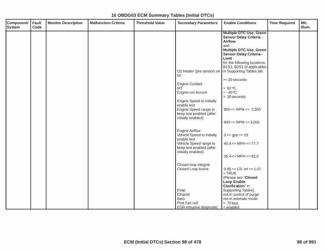
Component/System
FaultCode
Monitor Description Malfunction Criteria Threshold Value Secondary Parameters Enable Conditions Time Required MILIllum.
O2 Heater (pre sensor) onfor
Engine CoolantIATEngine run Accum
Engine Speed to initiallyenable testEngine Speed range tokeep test enabled (afterinitially enabled)
Engine AirflowVehicle Speed to initiallyenable testVehicle Speed range tokeep test enabled (afterinitially enabled)
Closed loop integralClosed Loop Active
EvapEthanolBaroPost fuel cellEGR Intrusive diagnostic
Multiple DTC Use_GreenSensor Delay Criteria -AirflowandMultiple DTC Use_GreenSensor Delay Criteria -Limitfor the following locations:B1S1, B2S1 (if applicable)in Supporting Tables tab.
>= seconds20
> ºC62> ºC-40> seconds30
<= RPM <=950 2,950
<= RPM <=900 3,050
<= gps <=2 15
<= MPH <=40.4 77.7
<= MPH <=35.4 82.0
<= C/L Int <=0.85 1.07= TRUE(Please see “ClosedLoop EnableClarification” inSupporting Tables).not in control of purgenot in estimate mode> kpa70= enabled
100
16 OBDG03 ECM Summary Tables (Initial DTCs)
ECM (Initial DTCs) Section 98 of 478 98 of 991

Component/System
FaultCode
Monitor Description Malfunction Criteria Threshold Value Secondary Parameters Enable Conditions Time Required MILIllum.
All post sensor heaterdelaysO2S Heater (post sensor)on Time
Predicted Catalyst tempFuel StateNumber of fueledcylinders
================When above conditionsare met: Fuel Enrichmode is entered.
================
During this test: EngineAirflow must staybetween:and the delta EngineAirflow over 12.5msecmust be :
= not active
= not active
>= sec80.0
<= ºC <=500 850= DFCO inhibit
>= cylinders1
==================
==================
<= gps <=1 20
<= gps2.0
101
16 OBDG03 ECM Summary Tables (Initial DTCs)
ECM (Initial DTCs) Section 99 of 478 99 of 991

Component/System
FaultCode
Monitor Description Malfunction Criteria Threshold Value Secondary Parameters Enable Conditions Time Required MILIllum.
Fuel SystemToo LeanBank 1
P0171 Determines if the fuelcontrol system is in alean condition, basedon the filtered long-term and short-termfuel trim.
The filtered long-term fueltrim metric
AND
The filtered short-termfuel trim metric(Note: any value below0.95 effectively nullifiesthe short-term fuel trimcriteria)
>= 1.300
>= 0.100
Engine speedBAROCoolant TempMAPInlet Air TempMAFFuel Level
Long Term Fuel Trim dataaccumulation:
Sometimes, certain Long-Term Fuel Trim Cells arenot utilized for controland/or diagnosis
Closed LoopLong Term FT
EGR Diag.
<rpm<400 6,500> kPa70
< °C <-20 150<kPa<10 255<°C<-20 150<g/s<1.0 512.0
> % or if fuel sender is10faulty the diagnostic willbypass the fuel levelcriteria.
> seconds of data55.0must accumulate on eachtrip, with at least 45.0seconds of data in thecurrent fuel trim cellbefore a pass or faildecision can be made.
(Please seeP0171_P0172_P0174_P0175 Long-Term FuelTrim Cell Usagein Supporting Tables for alist of cells utilized fordiagnosis)
EnabledEnabled(Please see "ClosedLoop EnableClarification" and "LongTerm FT Enable Criteria"in Supporting Tables.)
Intrusive Test Not Active
Frequency:100 msContinuous
Loop
Type B,2 Trips
102
16 OBDG03 ECM Summary Tables (Initial DTCs)
ECM (Initial DTCs) Section 100 of 478 100 of 991

Component/System
FaultCode
Monitor Description Malfunction Criteria Threshold Value Secondary Parameters Enable Conditions Time Required MILIllum.
Catalyst Diag.Post O2 Diag.Device ControlEVAP Diag.
No active DTC:
Intrusive Test Not ActiveIntrusive Test Not ActiveNot Active“tank pull down”Not Active
IAC_SystemRPM_FAMAP_SensorFAMAF_SensorFAMAF_SensorTFTKOAIR System FAEvapExcessPurgePsbl_FAEthanol CompositionSensor FAFuelInjectorCircuit_FAEngineMisfireDetected_FAEGRValvePerformance_FAEGRValveCircuit_FAMAP_EngineVacuumStatus
sAmbPresDfltdStatusTC_BoostPresSnsrFAO2S_Bank_1_Sensor_1_FA
103
16 OBDG03 ECM Summary Tables (Initial DTCs)
ECM (Initial DTCs) Section 101 of 478 101 of 991

Component/System
FaultCode
Monitor Description Malfunction Criteria Threshold Value Secondary Parameters Enable Conditions Time Required MILIllum.
Fuel SystemToo RichBank 1
P0172 Determines if the fuelcontrol system is in arich condition, basedon the filtered long-term fuel trim metric.
There are two methodsto determine a Richfault. They are Passiveand Intrusive. APassive Test decisioncan be made up untilthe time that purge isfirst enabled. From thatpoint forward, richfaults can only bedetected by turningpurge off intrusively.
Intrusive Test:If the filtered PurgeLong Term Fuel Trimmetric > , the0.730test passes withoutintrusively checking thefiltered Non-PurgeLong Term Fuel Trimmetric. However if thefiltered Purge LongTerm Fuel Trim metricis <= , purge is0.730ramped off todetermine if excesspurge vapor is thecause of the richcondition.
Performing intrusivetests too frequentlymay also affect EVAPand EPAIII emissions,
Passive Test: The filteredNon-Purge Long TermFuel Trim metric
AND
The filtered Short TermFuel Trim metric(Note: any value above1.05 effectively nullifiesthe short-term fuel trimcriteria)
Intrusive Test: For out of3intrusive segments, the5
filtered Purge Long TermFuel Trim metric
AND
The filtered Non-PurgeLong Term Fuel Trimmetric
AND
The filtered Short TermFuel Trim metric(Note: any value above1.05 effectively nullifiesthe short-term fuel trimcriteria)
Segment Def'n:Segments can last up to
seconds and are42separated by the lesser of
seconds of purge-on10.0time or enough time to
<= 0.725
<= 2.000
<= 0.730
<= 0.725
<= 2.000
Secondary Parametersand Enable Conditionsare identical to those forP0171, with the exceptionthat fuel level is notconsidered.
Frequency:100 msContinuous
Loop
Type B,2 Trips
104
16 OBDG03 ECM Summary Tables (Initial DTCs)
ECM (Initial DTCs) Section 102 of 478 102 of 991

Component/System
FaultCode
Monitor Description Malfunction Criteria Threshold Value Secondary Parameters Enable Conditions Time Required MILIllum.
and the executionfrequency of otherdiagnostics.
purge grams of vapor.10A maximum of 5completed segments or
attempts are allowed15for each intrusive test.After an intrusive testreport is completed,another intrusive testcannot occur for 300seconds to allow sufficienttime to purge excessvapors from the canister.During this period, fueltrim will pass if the filteredPurge Long Term FuelTrim metric > for at0.730least seconds,120.0indicating that the canisterhas been purged.
105
16 OBDG03 ECM Summary Tables (Initial DTCs)
ECM (Initial DTCs) Section 103 of 478 103 of 991

Component/System
FaultCode
Monitor Description Malfunction Criteria Threshold Value Secondary Parameters Enable Conditions Time Required MILIllum.
FuelPressureSensor "B"CircuitRange/Performance
P018B This DTC detects a fuelpressure sensorresponse stuck withinthe normal operatingrange using anintrusive test ( seeNotes)
Absolute value of fuelpressure change( as sensed duringintrusive test)
<= 30 kPa a] Diagnostic KeFRPD_b_FPSS_DiagEnbld
b] Engine Run Time
c] Engine Fuel Flow
d] Fu Pump ControlEnabled
e] Fu Pump Control State
f] Emissions Fuel LevelLow
g] Validity statusVeFRPD_b_FPSS_DataIntegrityOKIF
[1] FRP Circuit Low FaultActive (DTC P018C)[2] FRP Circuit High FaultActive (DTC P018D)[3] Fu Pump Circuit LowFault Active (DTC P0231)[4] Fu Pump Circuit HighFault Active (DTC P0232)[5] Fu Pump Circuit OpenFault Active (DTC P023F)[6] Reference VoltageFault Status ( DTCP0641)[7] Fu Pump ControlModule Driver Over-temperature Fault Active( DTC P1255)[8] Fu Pump Driver Mod
a] == TRUE
b] >= 5 sec
c] > calibration valueKeFRPD_dm_StkPresMinFuelFlow ( 0.047 gram/sec typical)
d] == TRUE
e] Normal OR Fu PresSnsr Stk Ctrl ( rationality)
f] <> TRUE
g] == TRUE
IF[1] <> TRUE
[2] <> TRUE
[3] <> TRUE
[4] <> TRUE
[5] <> TRUE
[6] <> Active This Key
[7] <> TRUE
[8] <> TRUE
1 sample /12.5 millisec
Intrusive TestDuration:Fu Flow -related( 5 to 12 sec)
Type B,2 Trips
106
16 OBDG03 ECM Summary Tables (Initial DTCs)
ECM (Initial DTCs) Section 104 of 478 104 of 991

Component/System
FaultCode
Monitor Description Malfunction Criteria Threshold Value Secondary Parameters Enable Conditions Time Required MILIllum.
Ign Sw RunStart Pstn CktLow Fault Active (DTCP129D)[9] Fu Pump DriverControl Mod Enable CktPerf Fault Active(DTCP12A6)
[9] <> TRUE
107
16 OBDG03 ECM Summary Tables (Initial DTCs)
ECM (Initial DTCs) Section 105 of 478 105 of 991

Component/System
FaultCode
Monitor Description Malfunction Criteria Threshold Value Secondary Parameters Enable Conditions Time Required MILIllum.
FuelPressureSensor "B"Circuit Low
P018C This DTC detects if thefuel pressure sensorcircuit is shorted low
Fuel Pressure SensorVoltage Percent, 5.0VNominal((Abs( 5.0V -SensorV_actual)/5.0V) *100)
<4.00
Ignition circuit input state High ( Run or Crank) 64 failures /80 samples
1 sample/12.5ms
Type B,2 Trips
108
16 OBDG03 ECM Summary Tables (Initial DTCs)
ECM (Initial DTCs) Section 106 of 478 106 of 991
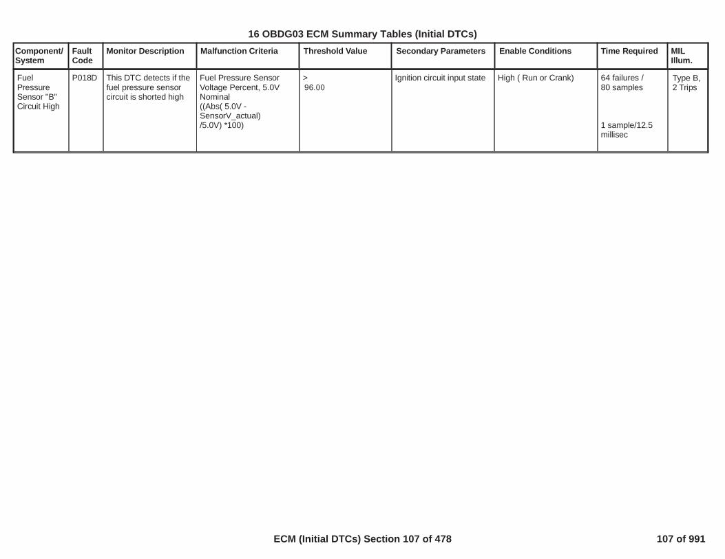
Component/System
FaultCode
Monitor Description Malfunction Criteria Threshold Value Secondary Parameters Enable Conditions Time Required MILIllum.
FuelPressureSensor "B"Circuit High
P018D This DTC detects if thefuel pressure sensorcircuit is shorted high
Fuel Pressure SensorVoltage Percent, 5.0VNominal((Abs( 5.0V -SensorV_actual)/5.0V) *100)
>96.00
Ignition circuit input state High ( Run or Crank) 64 failures /80 samples
1 sample/12.5millisec
Type B,2 Trips
109
16 OBDG03 ECM Summary Tables (Initial DTCs)
ECM (Initial DTCs) Section 107 of 478 107 of 991

Component/System
FaultCode
Monitor Description Malfunction Criteria Threshold Value Secondary Parameters Enable Conditions Time Required MILIllum.
SIDI HighPressureSensorPerformance- SingleAnalogSensor
P0191 The DTC Diagnoses askewed fuel rail sensorvia a comparison ofmeasured pressureand commanded/modeled pressure
Idle Test(Low Side Fuel Pressure -High Side Fuel Pressure)
<= MPa-1.000OR>= MPa1.000
Vehicle Speed
Pedal Position = 0 for
Battery Voltage
Low Pressure Fuel PumpPressure
Engine Run Time
Delay counts after pumpis turned off
SIDI High PressureSensor PerformanceDiagnostic Enabled
SIDI High PressureSensor Performance IdleTest Enabled
Enabled when a codeclear is not active or notexiting device control
Engine is not cranking
<= MPH0.62
Counts (12.5ms per200count)
>= Volts11
>= MPa0.275
>=P0089 - P163A - P228C -P228D - P0191 -KtFHPD_t_PumpCntrlEngRunThrsh(see supporting tables)
Enabled when a codeclear is not active or notexiting device control
Engine is not cranking
>=P0191 -KtFHPD_Cnt_SnsPrfIdlePumpOffDly
Idle Test > =240counts(12.5ms percount)
Type A,1 Trips
110
16 OBDG03 ECM Summary Tables (Initial DTCs)
ECM (Initial DTCs) Section 108 of 478 108 of 991

Component/System
FaultCode
Monitor Description Malfunction Criteria Threshold Value Secondary Parameters Enable Conditions Time Required MILIllum.
-----------------------------------
High Drive Test(Relief Pressure -Measured high Pressure)
-----------------------------------
Low Drive Test(Commanded high
------------------------------
<= MPa-1.60
------------------------------
-----------------------------------
Engine Speed
Desired High SidePressure
Vehicle Speed
Accelerator Pedal
Battery Voltage
Low Pressure Fuel PumpPressure
Engine Run Time
-----------------------------------
(see supporting tables)
-----------------------------------SIDI High PressureSensor PerformanceDiagnostic Enabled
SIDI High PressureSensor PerformanceHigh Drive Test Enabled
<= RPM <=1,000 3,000
<= MPa <=4 6
>= MPH22
>= %10
>= Volts11
>= MPa0.275
>=P0089 - P163A - P228C -P228D - P0191 -KtFHPD_t_PumpCntrlEngRunThrsh(see supporting tables)
Enabled when a codeclear is not active or notexiting device control
Engine is not cranking
-----------------------------------SIDI High PressureSensor PerformanceDiagnostic Enabled
-----------------------
KtFHPD_Cnt_SnsPrfIdlePumpOffDly runs in 12.5ms loopHigh Drive Test>=160counts(12.5ms percount)
-----------------------
LoDrive Test >=240
111
16 OBDG03 ECM Summary Tables (Initial DTCs)
ECM (Initial DTCs) Section 109 of 478 109 of 991

Component/System
FaultCode
Monitor Description Malfunction Criteria Threshold Value Secondary Parameters Enable Conditions Time Required MILIllum.
Pressure - Measured highPressure)
AND
Modeled InjectionPressure
-----------------------------------
Sensor Stuck TestMeasured High Pressure(max - min)
>= MPa3.000
>= MPa1.60
------------------------------
<= MPa0.100
Engine Speed
Desired High SidePressure
Vehicle Speed
Accelerator Pedal
Battery Voltage
Low Pressure Fuel PumpPressure
Engine Run Time
-----------------------------------
Engine Speed
SIDI High PressureSensor Performance LowDrive Test Enabled
<= RPM <=1,000 3,000
<= MPa <=4.00 6.00
>= MPH22
>= %10
>= Volts11
>= MPa0.275
>=P0089 - P163A - P228C -P228D - P0191 -KtFHPD_t_PumpCntrlEngRunThrsh(see supporting tables)
Enabled when a codeclear is not active or notexiting device control
Engine is not cranking
-----------------------------------SIDI High PressureSensor PerformanceDiagnostic Enabled
SIDI High PressureSensor PerformanceStuck Test Enabled
>= RPM2,000
counts(12.5ms percount)
-----------------------
Stuck TestEngine Run Time>=
112
16 OBDG03 ECM Summary Tables (Initial DTCs)
ECM (Initial DTCs) Section 110 of 478 110 of 991

Component/System
FaultCode
Monitor Description Malfunction Criteria Threshold Value Secondary Parameters Enable Conditions Time Required MILIllum.
Vehicle Speed>= MPH18.64
Enabled when a codeclear is not active or notexiting device controlEngine is not crankingAdditional EnableConditions: All must betrue (High Pressure Pumpis enabled and High Fuelpressure sensor ckt is Not(FA,FP or TFTKO) andHigh Pressure fuel pumpckt is Not (FA,FP orTFTKO) and Cam orCrank Sensor Not FA andIAT,IAT2,ECT Not FA andLow side Fuel PumpRelay ckt Not FA andEstimate fuel rail pressureis valid and Green Engine(In assembly plant) is notenabled and Not if lowfuel condition and Lowside Fuel Pump is on andInjector Flow Test is notactive and Device controlcommanded pressure isfalse and Device controlpump ckt enabled on isfalse and Enginemovement detected istrue and Manufacturersenable counter is 0)FlexFuel Sensor Not FAIgnition voltage out ofcorrelation error(P1682)not active Fuel InjCkt Not(FA or TFTKO) EST DriverNot(FA) Misfire detectedNot(FA) MAFR sensor Not(FA) MAPR sensor Not
P0089 - P163A -P228C - P228D -P0191 -KtFHPD_t_PumpCntrlEngRunThrsh(see supportingtables)orAccumulatingengine cranktime >=P0191 -KtFHPD_t_SnsPrfStuckCrankTmout(See SupportingTables)
113
16 OBDG03 ECM Summary Tables (Initial DTCs)
ECM (Initial DTCs) Section 111 of 478 111 of 991

Component/System
FaultCode
Monitor Description Malfunction Criteria Threshold Value Secondary Parameters Enable Conditions Time Required MILIllum.
Barometric Pressure
Inlet Air Temp
Fuel Temp
(FA) APSR Pedal sensorNot(FA) TPSR sensor Not(FA) VSPR speed sensorNot(FA) SystemRPM Not(FA) Manual Clutch notengaged or vehicle hasautomatic transmission Allcylinder are fuel enabledand>= KPA70.0
>= DegC-10.0
<= Temp degC <=-10126
114
16 OBDG03 ECM Summary Tables (Initial DTCs)
ECM (Initial DTCs) Section 112 of 478 112 of 991

Component/System
FaultCode
Monitor Description Malfunction Criteria Threshold Value Secondary Parameters Enable Conditions Time Required MILIllum.
HighPressureSensor Outof RangeLow
P0192 This DTC DiagnosesHigh Pressure SensorOut of Range Low
High Pressure FuelSensor Voltage
<= % of 5Vref4
Battery Voltage
SIDI High PressureSensor 1 Out of rangeTime Based Enabled
SIDI High PressureSensor 1 Out of rangeEngine SynchronousEnabled
>= Volts11
Engine Running
Both RunContinuouslyEngineSynchronousMode 800failures out of
samples1,000samples per4
engine rotation
Time BasedMode 400failures out of
samples5006.25 ms SampleContinuous
Type A,1 Trips
115
16 OBDG03 ECM Summary Tables (Initial DTCs)
ECM (Initial DTCs) Section 113 of 478 113 of 991

Component/System
FaultCode
Monitor Description Malfunction Criteria Threshold Value Secondary Parameters Enable Conditions Time Required MILIllum.
HighPressureSensor Outof RangeHigh
P0193 This DTC DiagnosesHigh Pressure SensorOut of Range High
High Pressure FuelSensor Voltage
>= % of 5Vref96 Battery Voltage SIDI High PressureSensor 1 Out of rangeTime Based Enabled
SIDI High PressureSensor 1 Out of rangeEngine SynchronousEnabled
>= Volts11
Engine Running
Both RunContinuouslyEngineSynchronousMode 800failures out of
samples1,000samples per4
engine rotation
Time BasedMode 400failures out of
samples5006.25 ms SampleContinuous
Type A,1 Trips
116
16 OBDG03 ECM Summary Tables (Initial DTCs)
ECM (Initial DTCs) Section 114 of 478 114 of 991

Component/System
FaultCode
Monitor Description Malfunction Criteria Threshold Value Secondary Parameters Enable Conditions Time Required MILIllum.
Injector 1Open Circuit- (SIDI)
P0201 This DTC DiagnosesInjector 1 enable lowside driver circuit forcircuit faults.
Low current through thelow side driver duringoperation indicates opencircuit
Open circuit:? 200 K ? impedancebetween signal andcontroller ground
Battery VoltageEngine Running
>= Volts11>= Seconds5
P062B not FA or TFTK
10failures out of20samples
100 ms /sampleContinuous
Type A,1 Trips
117
16 OBDG03 ECM Summary Tables (Initial DTCs)
ECM (Initial DTCs) Section 115 of 478 115 of 991
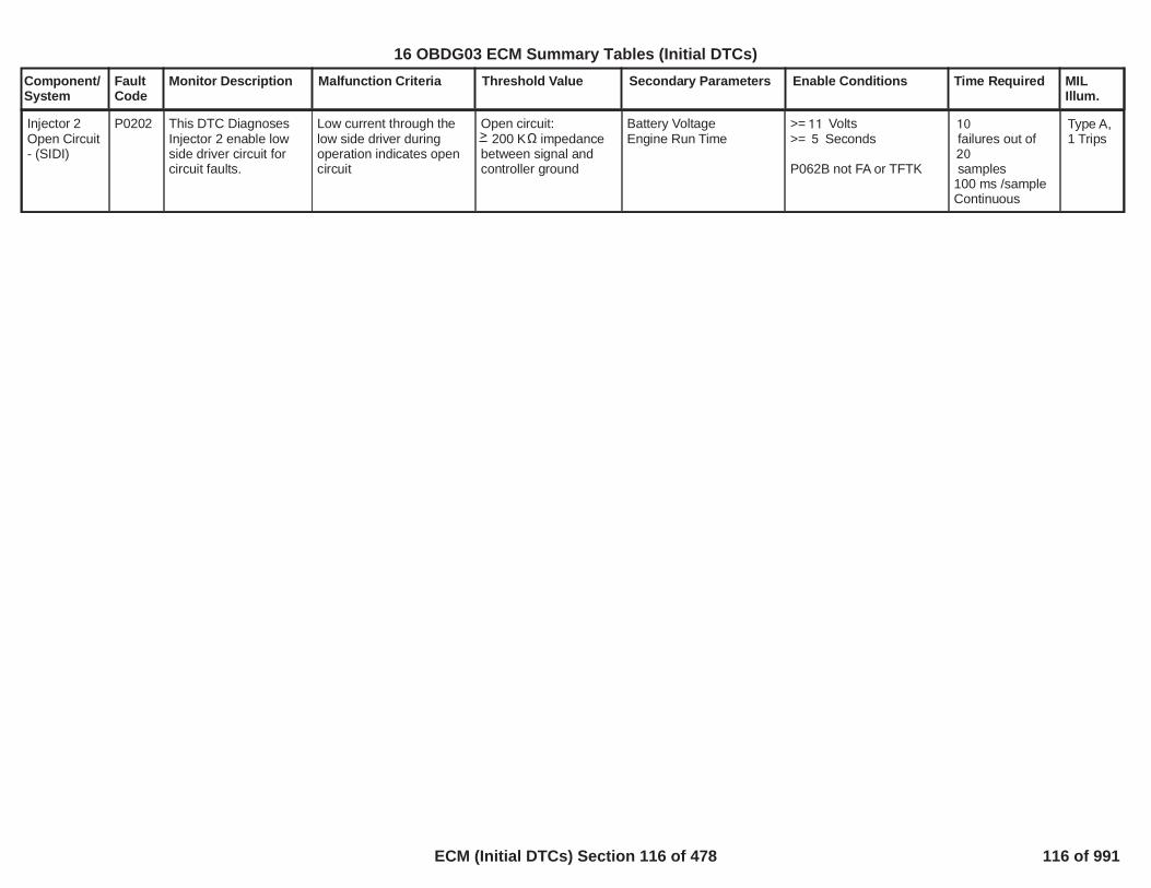
Component/System
FaultCode
Monitor Description Malfunction Criteria Threshold Value Secondary Parameters Enable Conditions Time Required MILIllum.
Injector 2Open Circuit- (SIDI)
P0202 This DTC DiagnosesInjector 2 enable lowside driver circuit forcircuit faults.
Low current through thelow side driver duringoperation indicates opencircuit
Open circuit:? 200 K ? impedancebetween signal andcontroller ground
Battery VoltageEngine Run Time
>= Volts11>= Seconds5
P062B not FA or TFTK
10failures out of20samples
100 ms /sampleContinuous
Type A,1 Trips
118
16 OBDG03 ECM Summary Tables (Initial DTCs)
ECM (Initial DTCs) Section 116 of 478 116 of 991
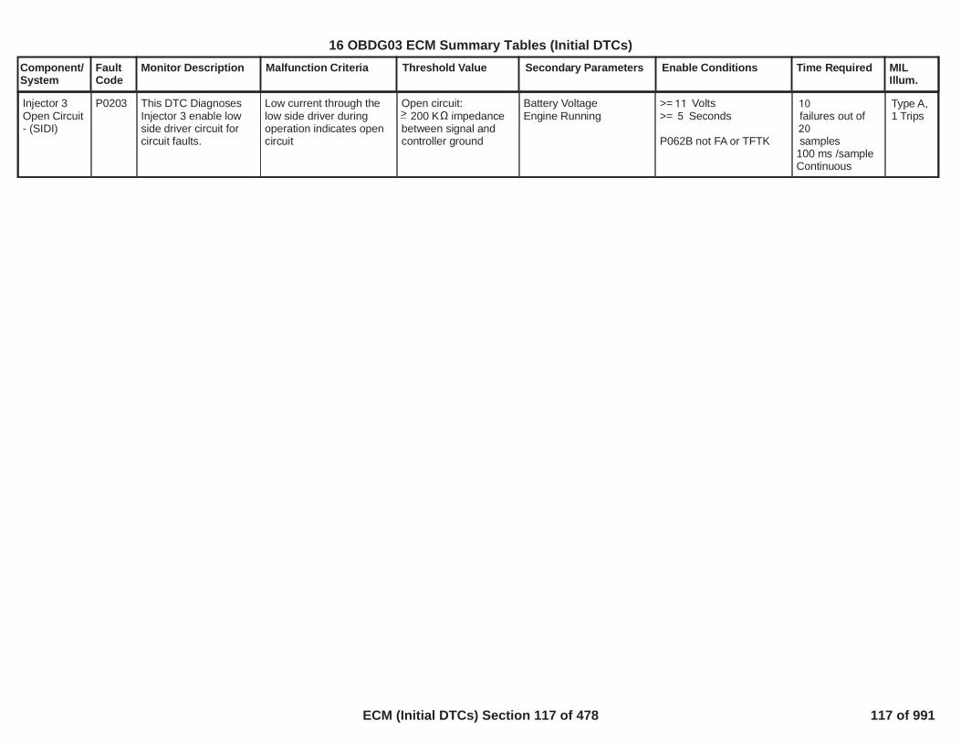
Component/System
FaultCode
Monitor Description Malfunction Criteria Threshold Value Secondary Parameters Enable Conditions Time Required MILIllum.
Injector 3Open Circuit- (SIDI)
P0203 This DTC DiagnosesInjector 3 enable lowside driver circuit forcircuit faults.
Low current through thelow side driver duringoperation indicates opencircuit
Open circuit:? 200 K ? impedancebetween signal andcontroller ground
Battery VoltageEngine Running
>= Volts11>= Seconds5
P062B not FA or TFTK
10failures out of20samples
100 ms /sampleContinuous
Type A,1 Trips
119
>
16 OBDG03 ECM Summary Tables (Initial DTCs)
ECM (Initial DTCs) Section 117 of 478 117 of 991

Component/System
FaultCode
Monitor Description Malfunction Criteria Threshold Value Secondary Parameters Enable Conditions Time Required MILIllum.
Injector 4Open Circuit- (SIDI)
P0204 This DTC DiagnosesInjector 4 enable lowside driver circuit forcircuit faults.
Low current through thelow side driver duringoperation indicates opencircuit
Open circuit:? 200 K ? impedancebetween signal andcontroller ground
Battery VoltageEngine Run Time
>= Volts11>= Seconds5
P062B not FA or TFTK
10failures out of20samples
100 ms /sampleContinuous
Type A,1 Trips
120
>
16 OBDG03 ECM Summary Tables (Initial DTCs)
ECM (Initial DTCs) Section 118 of 478 118 of 991

Component/System
FaultCode
Monitor Description Malfunction Criteria Threshold Value Secondary Parameters Enable Conditions Time Required MILIllum.
TPS2 CircuitLow
P0222 Detects a continuous orintermittent short oropen in TPS2 circuit
TPS2 Voltage < 0.250 Run/Crank voltage >6.41
No 5V reference error orfault for # 4 5V referencecircuit (P06A3)
/79 159counts;
counts57continuous;3.125 ms /countin the ECM mainprocessor
Type A,1 Trips
121
16 OBDG03 ECM Summary Tables (Initial DTCs)
ECM (Initial DTCs) Section 119 of 478 119 of 991
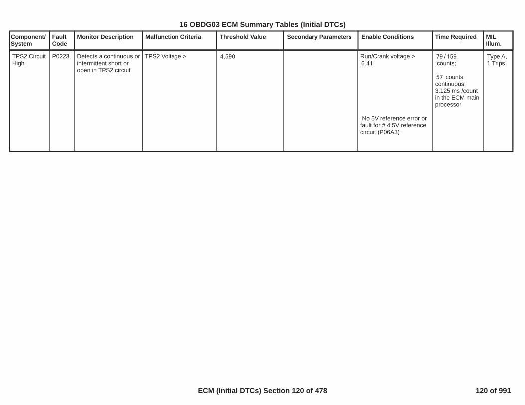
Component/System
FaultCode
Monitor Description Malfunction Criteria Threshold Value Secondary Parameters Enable Conditions Time Required MILIllum.
TPS2 CircuitHigh
P0223 Detects a continuous orintermittent short oropen in TPS2 circuit
TPS2 Voltage > 4.590 Run/Crank voltage >6.41
No 5V reference error orfault for # 4 5V referencecircuit (P06A3)
/79 159counts;
counts57continuous;3.125 ms /countin the ECM mainprocessor
Type A,1 Trips
122
16 OBDG03 ECM Summary Tables (Initial DTCs)
ECM (Initial DTCs) Section 120 of 478 120 of 991

Component/System
FaultCode
Monitor Description Malfunction Criteria Threshold Value Secondary Parameters Enable Conditions Time Required MILIllum.
Fuel PumpSecondaryCircuit Low
P0231 This DTC detects if thefuel pump controlcircuit is shorted to low
Power driver outputcurrent( Fuel Pump PowerModule Driver CircuitGround Shortenumeration)
Current >= 18.0 A a) FPPM configurationKeFRPR_e_ChassisFuelPresSysType
b) DiagnosticKeFRPR_b_FPPM_DrvrGshtDiagEnbld
c) Fuel Pump ControlEnable command
d) Fuel Pump ControlEnable time
e) System Voltage
f] FPPM Driver StatusAlive Rolling CountSample Faulted
g] Diagnostic feedbackreceived
h] Fuel Pump PowerModule output current
a) ==CeFRPR_e_ECM_FPPM_Sys
b) == TRUE
c) == TRUE
d) >= calibration valueKeFRPR_Cnt_FPPM_GshtDlyThrsh ( 0-80sample loops)
e) 9v < System V > 32v
f] <> TRUE
g] == TRUE
h] < 75A
64 failures / 80samples
1 sample/12.5millisec
Type A,1 Trips
123
16 OBDG03 ECM Summary Tables (Initial DTCs)
ECM (Initial DTCs) Section 121 of 478 121 of 991

Component/System
FaultCode
Monitor Description Malfunction Criteria Threshold Value Secondary Parameters Enable Conditions Time Required MILIllum.
Fuel PumpSecondaryCircuit High
P0232 This DTC detects if thefuel pump controlcircuit is shorted to highvoltage
Voltage offset relative tolow state level of dutycycle pulse measured atfuel pump circuit
> 4.0 V a) FPPM configurationKeFRPR_e_ChassisFuelPresSysType
b) DiagnosticKeFRPR_b_FPPM_DrvrPshtDiagEnbld
c) Fuel Pump ControlEnabled
d] FPPM Arbitrated FuPmp Duty Cycle Rate ofChange
e] System voltage
f] FPPM Driver StatusAlive Rolling CountSample Faulted
g] Diagnostic feedbackReceived
a) == CeFRPR_e_ECM_FPPM_Sys
b) == TRUE
c) == TRUE
d] >= calibration valueKeFRPR_cmp_FPPM_PshtDC_ROC_Min
e] 9v < System V > 32v
f] <> TRUE
g] == TRUE
64 failures / 80samples
1 sample / 12.5millisec
Type B,2 Trips
124
16 OBDG03 ECM Summary Tables (Initial DTCs)
ECM (Initial DTCs) Section 122 of 478 122 of 991

Component/System
FaultCode
Monitor Description Malfunction Criteria Threshold Value Secondary Parameters Enable Conditions Time Required MILIllum.
Desired Boost Pressure -Actual Boost Pressure
< refer toP0234_KtBSTD_p_CntrlDevNegLim-P0234_P0299_KtBSTD_p_CntrlDevAmbAirCorrin Supporting tables.
Diagnostic enable
Coolant temperature inrange
Intake Air temperature isin range
Ambient air pressure is inrange
Engine speed in range
Desired Boost Pressurein range
Desired Boost PressureDerivative in range
Wait for steady state:
No active DTCs:
Pressure Control has tobe in closed loop.
No Device control activefor WG and Compresseorrecirculation valve.
True
> °C-40.0< °C130.0
> °C-40.0< °C80.0
> kPa60.0< kPa120.0
> rpm1,600< rpm6,000
> kPa140.0< kPa300.0
> kPa/s-75.0< kPa/s75.0
> refer toP0234_P0299_KtBSTD_t_CntrlDevEnblDelayin Supporting tables.
BSTR_b_PCA_CktFABSTR_b_TurboBypassCktFAECT_Sensor_FAIAT_SensorFABSTR_b_BoostSnsrFAAmbientAirDefault
failures out14of samples15
100ms / sample
Turbo/SuperChargerEngineOverboostTurbocharger withwastegate.Notsupercharger withmechanicalcompressor
P0234 Detect Negative BoostPressure ControlDeviation
Type A,1 Trips
Actual Boost Pressure > refer to Dev Diagnostic enable True failures out100
125
16 OBDG03 ECM Summary Tables (Initial DTCs)
ECM (Initial DTCs) Section 123 of 478 123 of 991
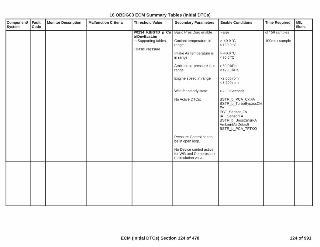
Component/System
FaultCode
Monitor Description Malfunction Criteria Threshold Value Secondary Parameters Enable Conditions Time Required MILIllum.
P0234_KtBSTD_p_CntrlDevBasLimin Supporting tables.
+Basic Pressure
Basic Pres Diag enable
Coolant temperature inrange
Intake Air temperature isin range
Ambient air pressure is inrange
Engine speed in range
Wait for steady state:
No Active DTCs:
Pressure Control has tobe in open loop.
No Device control activefor WG and Compresseorrecirculation valve.
False
> °C-40.0< °C130.0
> °C-40.0< °C80.0
> kPa60.0< kPa120.0
> rpm2,000< rpm3,500
> Seconds2.00
BSTR_b_PCA_CktFABSTR_b_TurboBypassCktFAECT_Sensor_FAIAT_SensorFABSTR_b_BoostSnsrFAAmbientAirDefaultBSTR_b_PCA_TFTKO
of samples150
100ms / sample
126
16 OBDG03 ECM Summary Tables (Initial DTCs)
ECM (Initial DTCs) Section 124 of 478 124 of 991

Component/System
FaultCode
Monitor Description Malfunction Criteria Threshold Value Secondary Parameters Enable Conditions Time Required MILIllum.
See tableP0101, P0106, P010B,P0121, P0236, P1101:Turbocharger IntakeFlow RationalityDiagnostic FailureMatrixfor combinationsof model failures that canset this DTC.
MAF model fails whenABS(Measured Flow –Modeled Air Flow) Filtered
MAP1 model fails whenABS(Measured MAP –MAP Model 1) Filtered
MAP2 model fails whenABS(Measured MAP –MAP Model 2) Filtered
MAP3 model fails whenABS(Measured MAP –MAP Model 3) Filtered
TIAP1 model fails whenABS(Measured TIAP -TIAP Model 1) Filtered
TPS model fails whenFiltered Throttle ModelError
TIAP Correlation modelfails whenHigh Engine Air Flow isTRUE ANDMeasured TIAP -measured MAP - offset asa function of engine
> grams/sec20.0
> kPa30.0
> kPa30.0
> kPa30.0
> kPa30.0
> kPa*(g/s)300
Engine SpeedEngine SpeedCoolant TempCoolant TempIntake Air TempIntake Air Temp
Minimum total weightfactor (all factorsmultiplied together)
See Residual WeightFactor tables.
-
>= RPM400<= RPM6,000> Deg C-7< Deg C130> Deg C-20< Deg C125
>= 0.50
Modeled Air Flow Errormultiplied byP0101, P0106, P010B,P0121, P012B, P0236,P1101: MAF1 ResidualWeight Factor based onRPMandP0101, P0106, P010B,P0121, P012B, P0236,P1101: MAF1 ResidualWeight Factor based onMAF Est
MAP Model 1 Errormultiplied byP0101, P0106, P0121,P012B, P0236, P1101:MAP1 Residual WeightFactor based on RPM
MAP Model 2 Errormultiplied byP0101, P0106, P0121,P012B, P0236, P1101:MAP2 Residual WeightFactor based on RPM
MAP Model 3 Errormultiplied by
Continuous
Calculation areperformed every12.5 msec
Turbocharger BoostPressure(TIAP)SensorPerformance(single turbo)
P0236 Determines if theTurbocharger Boost(TIAP) PressureSensor input is stuckwithin the normaloperating range
Type B,2 Trips
127
16 OBDG03 ECM Summary Tables (Initial DTCs)
ECM (Initial DTCs) Section 125 of 478 125 of 991

Component/System
FaultCode
Monitor Description Malfunction Criteria Threshold Value Secondary Parameters Enable Conditions Time Required MILIllum.
speedSee tableP0101, P0106, P0121,P0236, P1101: TIAP-MAP Correlation Offset
OR
Low Engine Air Flow isTRUE ANDMeasured TIAP -measured Baro - offset asa function of enginespeedSee tableP0101, P0106, P0121,P0236, P1101: TIAP-Baro Correlation Offset
TIAP Correlation is validwhenHigh Engine Air Flow hasbeen TRUE for a period oftimeORLow Engine Air Flow hasbeen TRUE for a period oftime
High Engine Air Flow isTRUE whenMass Air Flow
AND
> kPa30.0
> kPa30.0
> seconds1.0
> seconds1.0
> a threshold ingm/sec as a functionof engine speed SeetableP0101, P0106, P0121,P0236, P1101: TIAP-MAP Correlation MinAir Flow
No Active DTCs:
No Pending DTCs:
P0101, P0106, P0121,P012B, P0236, P1101:MAP3 Residual WeightFactor based on RPM
TIAP Model 1 Errormultiplied byP0101, P0106, P0121,P0236, P1101: TIAPResidual Weight Factorbased on RPM
Filtered Throttle ModelError multiplied byP0101, P0106, P0121,P012B, P0236, P1101:TPS Residual WeightFactor based on RPM
MAP_SensorCircuitFAEGRValvePerformance_FAMAF_SensorCircuitFACrankSensor_FAECT_Sensor_FAIAT_SensorFAMnfdTempSensorFATC_BoostPresSnsrCktFAAmbientAirDefault
EGRValve_FPECT_Sensor_Ckt_FPIAT_SensorCircuitFPMnfdTempSensorCktFP
128
16 OBDG03 ECM Summary Tables (Initial DTCs)
ECM (Initial DTCs) Section 126 of 478 126 of 991

Component/System
FaultCode
Monitor Description Malfunction Criteria Threshold Value Secondary Parameters Enable Conditions Time Required MILIllum.
Manifold Pressure
ANDFiltered Mass Air Flow -Mass Air Flow
Low Engine Air Flow isTRUE whenMass Air Flow
ANDManifold Pressure
ANDMass Air Flow - FilteredMass Air Flow
> a threshold in kPa asa function of enginespeed See tableP0101, P0106, P0121,P0236, P1101: TIAP-MAP Correlation MinMAP
< gm/sec3.0
< a threshold in gm/sec as a function ofengine speedSee tableP0101, P0106, P0121,P0236, P1101: TIAP-Baro Correlation MaxAir Flow
< a threshold in kPa asa function of enginespeedSee tableP0101, P0106, P0121,P0236, P1101: TIAP-Baro Correlation MaxMAP
< gm/sec2.0
Turbocharger BoostPressureORTurbocharger BosstPressure
OR
< kPa50.0
> kPa115.0
Time between currentignition cycle and the lasttime the engine wasrunning
Engine is not rotating
-
> seconds10.0
failures out of4samples5
1 sample every12.5 msec
129
16 OBDG03 ECM Summary Tables (Initial DTCs)
ECM (Initial DTCs) Section 127 of 478 127 of 991

Component/System
FaultCode
Monitor Description Malfunction Criteria Threshold Value Secondary Parameters Enable Conditions Time Required MILIllum.
ABS(Manifold Pressure -Baro Pressure)ANDABS(Turbocharger BoostPressure - ManifoldPressure)ANDABS(Turbocharger BoostPressure - Baro Pressure)
<= kPa10.0
> kPa10.0
> kPa10.0
No Active DTCs:
No Pending DTCs:
EngineModeNotRunTimerErrorMAP_SensorCircuitFAAAP_SnsrCktFAAAP2_SnsrCktFA
MAP_SensorCircuitFPAAP_SnsrCktFPAAP2_SnsrCktFP
130
16 OBDG03 ECM Summary Tables (Initial DTCs)
ECM (Initial DTCs) Section 128 of 478 128 of 991

Component/System
FaultCode
Monitor Description Malfunction Criteria Threshold Value Secondary Parameters Enable Conditions Time Required MILIllum.
Turbocharger BoostPressureSensorCircuit Low(Gen III)
P0237 Detects a continuousshort to low in eitherthe signal circuit or theturbocharger boostpressure sensor.
Turbocharger BoostPressure Voltage < % of 5 Volt19.4
Range(This is equal to 0.97Volts, or kPa)49.9
failures out320of samples400
1 sample every12.5 msec
Type B,2 Trips
131
16 OBDG03 ECM Summary Tables (Initial DTCs)
ECM (Initial DTCs) Section 129 of 478 129 of 991

Component/System
FaultCode
Monitor Description Malfunction Criteria Threshold Value Secondary Parameters Enable Conditions Time Required MILIllum.
Turbocharger BoostPressureSensorCircuit High(Gen III)
P0238 Detects an opensensor ground,continuous short tohigh or open in eitherthe signal circuit or theturbocharger boostpressure sensor.
Turbocharger BoostPressure Voltage > % of 5 Volt78.0
Range(This is equal to 3.90Volts, or kPa)299.0
failures out320of samples400
1 sample every12.5 msec
Type B,2 Trips
132
16 OBDG03 ECM Summary Tables (Initial DTCs)
ECM (Initial DTCs) Section 130 of 478 130 of 991

Component/System
FaultCode
Monitor Description Malfunction Criteria Threshold Value Secondary Parameters Enable Conditions Time Required MILIllum.
Fuel PumpSecondaryCircuit Open
P023F This DTC detects if thefuel pump controlcircuit is open
Output driver current( Fuel Pump PowerModule Driver CircuitOpen enumeration)
Current <= 1.0 A a) FPPM configurationKeFRPR_e_ChassisFuelPresSysType
b) DiagnosticKeFRPR_b_FPPM_OpenCktDiagEnbld
c) Arbitrated Fu Pmp DutyCycle ( %)
d] Fuel Pump ControlEnable Faulted
e] FPPM Fu Pmp DriverOver-temperature Faulted
f] FPPM Driver StatusAlive Rolling CountSample Faulted
g] Diagnostic feedbackreceived
h] System Voltage
a) == CeFRPR_e_ECM_FPPM_Sys
b) == TRUE
c) > calibration valueKeFRPR_Pct_FPPM_OpenCktDC_Thrsh( 30% - 60%)
d] <> TRUE
e] <> TRUE
f] <> TRUE
g] == TRUE
h] 9v < System V > 32v
40 test failures /80 test samples;
1 sample/12.5ms
Type A,1 Trips
133
16 OBDG03 ECM Summary Tables (Initial DTCs)
ECM (Initial DTCs) Section 131 of 478 131 of 991

Component/System
FaultCode
Monitor Description Malfunction Criteria Threshold Value Secondary Parameters Enable Conditions Time Required MILIllum.
TurbochargerWastegate /Supercharger BoostSolenoid AControlCircuit
P0243 Detect TurbochargerBoost Solenoid -OpenCircuit
ECM detects thatcommanded and actualstates of output driver donot match because theoutput is open circuit
Open circuit:
200 K impedencebetween signal andcontroller ground
Diagnostic Enabled
EnabledPowertrain relayVoltage
Ignition run crank voltage
Engine is not cranking
Diagnostic System notDisabled
True
>= Volts11.0
> Volts5.00
failures out of10samples20
100ms / sample
Type A,1 Trips
Note: Incertaincontrollers P0245may alsoset(TurbochargerWastegate /SuperchargerBoostSolenoidAControlCircuitLow)
134
16 OBDG03 ECM Summary Tables (Initial DTCs)
ECM (Initial DTCs) Section 132 of 478 132 of 991

Component/System
FaultCode
Monitor Description Malfunction Criteria Threshold Value Secondary Parameters Enable Conditions Time Required MILIllum.
TurbochargerWastegate /Supercharger BoostSolenoid AControlCircuit Low
P0245 Detect TurbochargerBoost Solenoid -Shorted to ground
ECM detects thatcommanded and actualstates of output driver donot match because theoutput is shorted toground
Short to ground:
0.5 impedencebetween signal andcontroller ground
Diagnostic Enabled
EnabledPowertrain relayVoltage
Ignition run crank voltage
Engine is not cranking
Diagnostic System notDisabled
True
>= Volts11.0
> Volts5.00
failures out of10samples20
100ms / sample
Type A,1 Trips
Note: Incertaincontrollers P0243may alsoset(TurbochargerWastegate /SuperchargerBoostSolenoidAControlCircuit)
135
16 OBDG03 ECM Summary Tables (Initial DTCs)
ECM (Initial DTCs) Section 133 of 478 133 of 991

Component/System
FaultCode
Monitor Description Malfunction Criteria Threshold Value Secondary Parameters Enable Conditions Time Required MILIllum.
TurbochargerWastegate /Supercharger BoostSolenoid AControlCircuit High
P0246 Detect TurbochargerBoost Solenoid -Shorted to Power
ECM detects thatcommanded and actualstates of output driver donot match because theoutput is shorted to power
Short to power:
0.5 impedencebetween signal andcontroller power
Diagnostic Enabled
EnabledPowertrain relayVoltage
Ignition run crank voltage
Engine is not cranking
Diagnostic System notDisabled
True
>= Volts11.0
> Volts5.00
failures out of10samples20
100ms / sample
Type A,1 Trips
136
16 OBDG03 ECM Summary Tables (Initial DTCs)
ECM (Initial DTCs) Section 134 of 478 134 of 991

Component/System
FaultCode
Monitor Description Malfunction Criteria Threshold Value Secondary Parameters Enable Conditions Time Required MILIllum.
Injector 1Low sidecircuitshorted toground(SIDI)
P0261 This DTC DiagnosesInjector 1 enable lowside driver circuit forcircuit faults.
Voltage low across lowside drive during off stateindicates short-to-ground
Short to ground:? 1 volt between signaland controller ground
Battery VoltageEngine Run Time
>= Volts11>= Seconds5
P062B not FA or TFTK
10failures out of20samples
100 ms /sampleContinuous
Type A,1 Trips
137
16 OBDG03 ECM Summary Tables (Initial DTCs)
ECM (Initial DTCs) Section 135 of 478 135 of 991

Component/System
FaultCode
Monitor Description Malfunction Criteria Threshold Value Secondary Parameters Enable Conditions Time Required MILIllum.
Injector 1Low sidecircuitshorted topower (SIDI)
P0262 This DTC DiagnosesInjector 1 enable lowside driver circuit forcircuit faults.
Voltage High across lowside driver during Onstate indicates short topower
Short to power:25 amp >= throughlow side driver
Battery VoltageEngine Run Time
>= Volts11>= Seconds5
P062B not FA or TFTK
10failures out of20samples
100 ms /sampleContinuous
Type A,1 Trips
138
16 OBDG03 ECM Summary Tables (Initial DTCs)
ECM (Initial DTCs) Section 136 of 478 136 of 991

Component/System
FaultCode
Monitor Description Malfunction Criteria Threshold Value Secondary Parameters Enable Conditions Time Required MILIllum.
Injector 2Low sidecircuitshorted toground(SIDI)
P0264 This DTC DiagnosesInjector 2 enable lowside driver circuit forcircuit faults.
Voltage low across lowside drive during off stateindicates short-to-ground
Short to ground:? 1 volt between signaland controller ground
Battery VoltageEngine Run Time
>= Volts11>= Seconds5
P062B not FA or TFTK
10failures out of20samples
100 ms /sampleContinuous
Type A,1 Trips
139
<
16 OBDG03 ECM Summary Tables (Initial DTCs)
ECM (Initial DTCs) Section 137 of 478 137 of 991
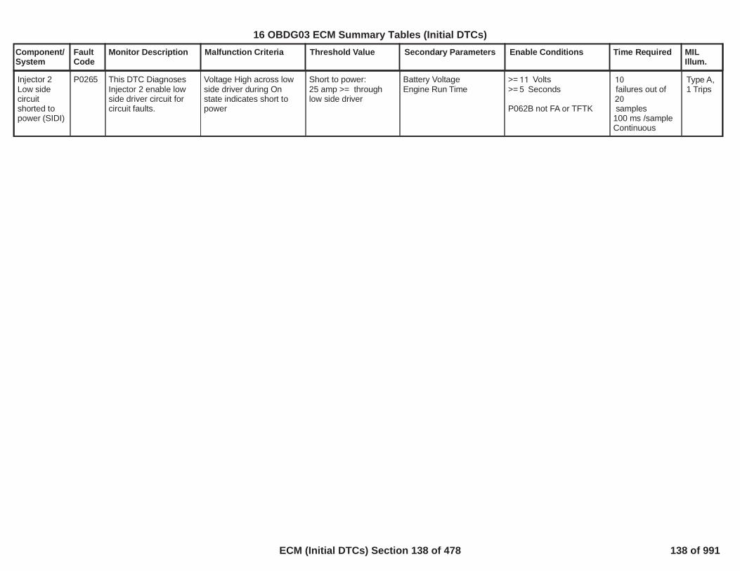
Component/System
FaultCode
Monitor Description Malfunction Criteria Threshold Value Secondary Parameters Enable Conditions Time Required MILIllum.
Injector 2Low sidecircuitshorted topower (SIDI)
P0265 This DTC DiagnosesInjector 2 enable lowside driver circuit forcircuit faults.
Voltage High across lowside driver during Onstate indicates short topower
Short to power:25 amp >= throughlow side driver
Battery VoltageEngine Run Time
>= Volts11>= Seconds5
P062B not FA or TFTK
10failures out of20samples
100 ms /sampleContinuous
Type A,1 Trips
140
16 OBDG03 ECM Summary Tables (Initial DTCs)
ECM (Initial DTCs) Section 138 of 478 138 of 991

Component/System
FaultCode
Monitor Description Malfunction Criteria Threshold Value Secondary Parameters Enable Conditions Time Required MILIllum.
Injector 3Low sidecircuitshorted toground(SIDI)
P0267 This DTC DiagnosesInjector 3 enable lowside driver circuit forcircuit faults.
Voltage low across lowside drive during off stateindicates short-to-ground
Short to ground:? 1 volt between signaland controller ground
Battery VoltageEngine Run Time
>= Volts11>= Seconds5
P062B not FA or TFTK
10failures out of20samples
100 ms /sampleContinuous
Type A,1 Trips
141
<
16 OBDG03 ECM Summary Tables (Initial DTCs)
ECM (Initial DTCs) Section 139 of 478 139 of 991

Component/System
FaultCode
Monitor Description Malfunction Criteria Threshold Value Secondary Parameters Enable Conditions Time Required MILIllum.
Injector 3Low sidecircuitshorted topower (SIDI)
P0268 This DTC DiagnosesInjector 3 enable lowside driver circuit forcircuit faults.
Voltage High across lowside driver during Onstate indicates short topower
Short to power:25 amp >= throughlow side driver
Battery VoltageEngine Run Time
>= Volts11>= Seconds5
P062B not FA or TFTK
10failures out of20samples
100 ms /sampleContinuous
Type A,1 Trips
142
16 OBDG03 ECM Summary Tables (Initial DTCs)
ECM (Initial DTCs) Section 140 of 478 140 of 991
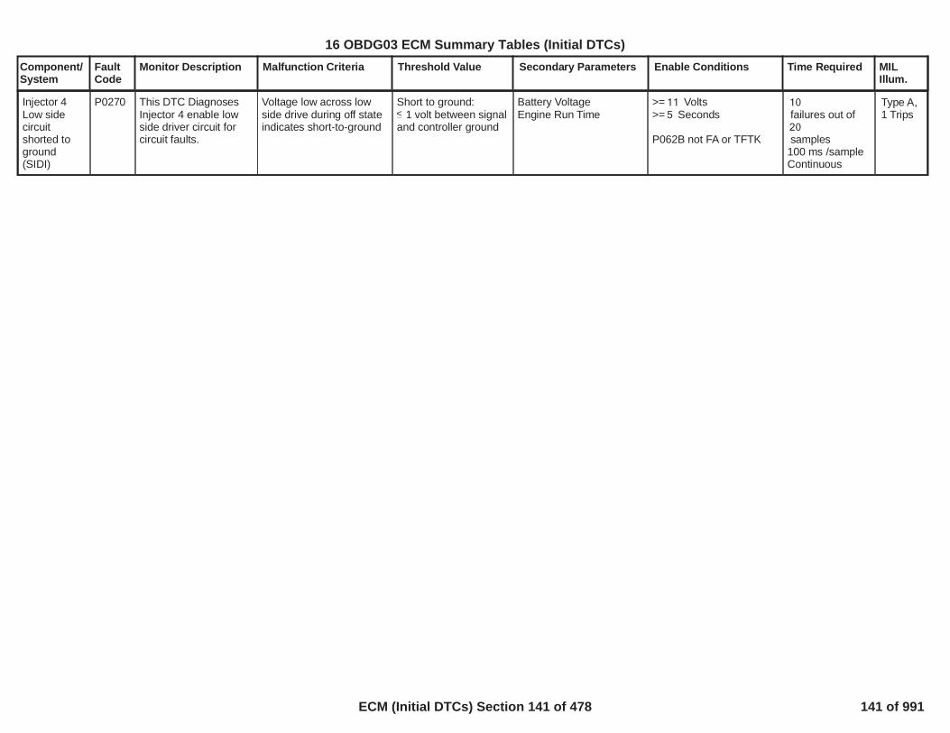
Component/System
FaultCode
Monitor Description Malfunction Criteria Threshold Value Secondary Parameters Enable Conditions Time Required MILIllum.
Injector 4Low sidecircuitshorted toground(SIDI)
P0270 This DTC DiagnosesInjector 4 enable lowside driver circuit forcircuit faults.
Voltage low across lowside drive during off stateindicates short-to-ground
Short to ground:? 1 volt between signaland controller ground
Battery VoltageEngine Run Time
>= Volts11>= Seconds5
P062B not FA or TFTK
10failures out of20samples
100 ms /sampleContinuous
Type A,1 Trips
143
<
16 OBDG03 ECM Summary Tables (Initial DTCs)
ECM (Initial DTCs) Section 141 of 478 141 of 991

Component/System
FaultCode
Monitor Description Malfunction Criteria Threshold Value Secondary Parameters Enable Conditions Time Required MILIllum.
Injector 4Low sidecircuitshorted topower (SIDI)
P0271 This DTC DiagnosesInjector 4 enable lowside driver circuit forcircuit faults.
Voltage High across lowside driver during Onstate indicates short topower
Short to power:25 amp >= throughlow side driver
Battery VoltageEngine Run Time
>= Volts11>= Seconds5
P062B not FA or TFTK
10failures out of20samples
100 ms /sampleContinuous
Type A,1 Trips
144
16 OBDG03 ECM Summary Tables (Initial DTCs)
ECM (Initial DTCs) Section 142 of 478 142 of 991

Component/System
FaultCode
Monitor Description Malfunction Criteria Threshold Value Secondary Parameters Enable Conditions Time Required MILIllum.
Desired Boost Pressure -Actual Boost Pressure
<refr toP0299_KtBSTD_p_CntrlDevPosLim+P0234_P0299_KtBSTD_p_CntrlDevAmbAirCorrin Supporting tables.
Diagnostic enable
Coolant temperature inrange
Intake Air temperature isin range
Ambient air pressure is inrange
Engine speed in range
Desired Boost Pressurein range
Desired Boost PressureDerivative in range
Wait for steady state:
No active DTCs:
Pressure Control has tobe in closed loop.
No Device control activefor WG and Compresseorrecirculation valve.
True
> °C-40.0< °C130.0
> °C-40.0< °C80.0
> kPa60.0< kPa120.0
> rpm1,600< rpm6,000
> kPa140.0< kPa300.0
> kPa/s-75.0< kPa/s75.0
> refer toP0234_P0299_KtBSTD_t_CntrlDevEnblDelayin Supporting tables.
BSTR_b_PCA_CktFABSTR_b_TurboBypassCktFAECT_Sensor_FAIAT_SensorFABSTR_b_BoostSnsrFAAmbientAirDefault
failures out of14samples15
100ms / sample
Turbo/SuperChargerEngineUnderboostTurbocharger withwastegate.Notsupercharger withmechanicalcompressor
P0299 Detect Positive BoostPressure ControlDeviation
Type A,1 Trips
145
16 OBDG03 ECM Summary Tables (Initial DTCs)
ECM (Initial DTCs) Section 143 of 478 143 of 991

Component/System
FaultCode
Monitor Description Malfunction Criteria Threshold Value Secondary Parameters Enable Conditions Time Required MILIllum.
Actual Boost Pressuredelta
(the delta is limited bythese tables:refer toMax:P0299_KtBSTD_p_CntrlDevDsrdRtHiMin:P0299_KtBSTD_p_CntrlDevDsrdRtLoin Supporting tables.
< 10.00 Diagnostic enableRateBas Diagostic enable
Coolant temperature inrange
Intake Air temperature isin range
Ambient air pressure is inrange
Desired Boost Pressurein range
Desired Boost PressureDerivative in Hyst.Rang
Engine speed is in range
Wait for steaty state:
No active DTCs:
Pressure Control has tobe in open loop.
No Device control activefor WG and Compresseorrecirculation valve.
TrueFalse
> °C-40.0< °C130.0
> °C-40.0< °C80.0
> kPa60.0< kPa120.0
> kPa140.0< kPa300.0
Enable Limit: 20.0Disable Limit: -20.0
> rpm2,000< rpm3,500
> Seconds0.20
BSTR_b_PCA_CktFABSTR_b_TurboBypassCktFAECT_Sensor_FAIAT_SensorFABSTR_b_BoostSnsrFAAmbientAirDefault
failures out of10samples20
100ms / sample
146
16 OBDG03 ECM Summary Tables (Initial DTCs)
ECM (Initial DTCs) Section 144 of 478 144 of 991

Component/System
FaultCode
Monitor Description Malfunction Criteria Threshold Value Secondary Parameters Enable Conditions Time Required MILIllum.
RandomMisfireDetected
Cylinder 1MisfireDetected
Cylinder 2MisfireDetected
Cylinder 3MisfireDetected
Cylinder 4MisfireDetected
P0300
P0301
P0302
P0303
P0304
These DTC’s willdetermine if a randomor a cylinder specificmisfire is occurring bymonitoring variousterms derived fromcrankshaft velocity.The pattern of misfire istaken into account toselect the propermisfire thesholds..Additionally, the patternof crankshaftacceleration after themisfire is checked todifferentiate betweenreal misfire and othersources of crank shaftnoise such as roughroad.The rate of misfire overan interval is comparedto both emissions andcatalyst damagingthresholds.
Crankshaft DecelerationValue(s) vs.Engine Speed andEngine load
The equation used tocalculate decelerationvalue is tailored to specificvehicle operatingconditions.The selection of theequation used is based onthe 1st single cylindercontinuous misfirethreshold tablesencountered that are notmax of range. If all tablesare max of range at agiven speed/load, thatspeed load region is anUndetectable regionsee Algorithm DescriptionDocument for additionaldetails.
SINGLE CYLINDERCONTINUOUS MISFIRE(
(Medres_DecelMedres_Jerk
OR (Medres_DecelMedres_Jerk
OR (Lores_DecelLores_Jerk
OR (Lores_DecelLores_Jerk
OR RevBalanceTime)
- see details ofthresholds onSupporting Tables Tab
> ANDIdleSCD_Decel> )IdleSCD_Jerk
> ANDSCD_Decel> )SCD_Jerk
> ANDIdleCyl_Decel> )IdleCyl_Jerk
> ANDCylModeDecel> )CylModeJerk
>RevMode_Decel
Engine Run Time
Engine Coolant TempOr If ECT at startupThen ECT
System Voltage+ Throttle delta- Throttle delta
Early Termination option:(used on plug ins thatmay not have enoughengine run time at end oftrip for normal interval tocomplete.)
> 2 crankshaft revolution
ºC < ECT < ºC-7 130< ºC-7
ºC < ECT < ºC21 130
< volts <9.00 32.00< % per 25 ms95.00< % per 25 ms95.00
Not Enabled
EmissionExceedence =any ( ) failed5200 rev blocksout of ( ) 20016rev block tests
Failure reportedfor (1)Exceedence in1st ( ) 200 rev16block tests, or( )4Exceedencesthereafter.
ORwhen EarlyTerminationReporting =Enabled andengine rev> revs1,000and < 3,200revs at end oftrip
any CatalystExceedence =( ) 200 rev1block as datasupports forcatalyst damage.
Type B,2 Trips(MilFlasheswithCatalystdamagelevel ofMisfire)
16 OBDG03 ECM Summary Tables (Initial DTCs)
ECM (Initial DTCs) Section 145 of 478 145 of 991

Component/System
FaultCode
Monitor Description Malfunction Criteria Threshold Value Secondary Parameters Enable Conditions Time Required MILIllum.
Other patterns of misfireuse adjustments to thesingle cylinder continuousmisfire threshold tables:
RANDOM MISFIREUse random misfire
thresholds If no misfire for
(Medres_Decel
ANDMedres_Jerk)
OR (Medres_Decel
ANDMedres_Jerk)
OR (Lores_Decel
ANDLores_Jerk)
OR (Lores_Decel
ANDLores_Jerk)
OR RevBalanceTime
> Engine Cycles6
> *IdleSCD_DecelRandom_SCD_Decel
> *IdleSCD_JerkRandom_SCD_Jerk
> *SCD_DecelRandom_SCD_Decel
> *SCD_JerkRandom_SCD_Jerk
> *IdleCyl_DecelRandomCylModDecel
> *IdleCyl_JerkRandomCylModJerk
> *CylModeDecelRandomCylModDecel
> *CylModeJerkRandomCylModJerk
> *RevMode_DecelRandomRevModDecl
Catalyst Failurereported with (1or 3)Exceedences inFTP, or (1)Exceedenceoutside FTP.
Continuous
16 OBDG03 ECM Summary Tables (Initial DTCs)
ECM (Initial DTCs) Section 146 of 478 146 of 991
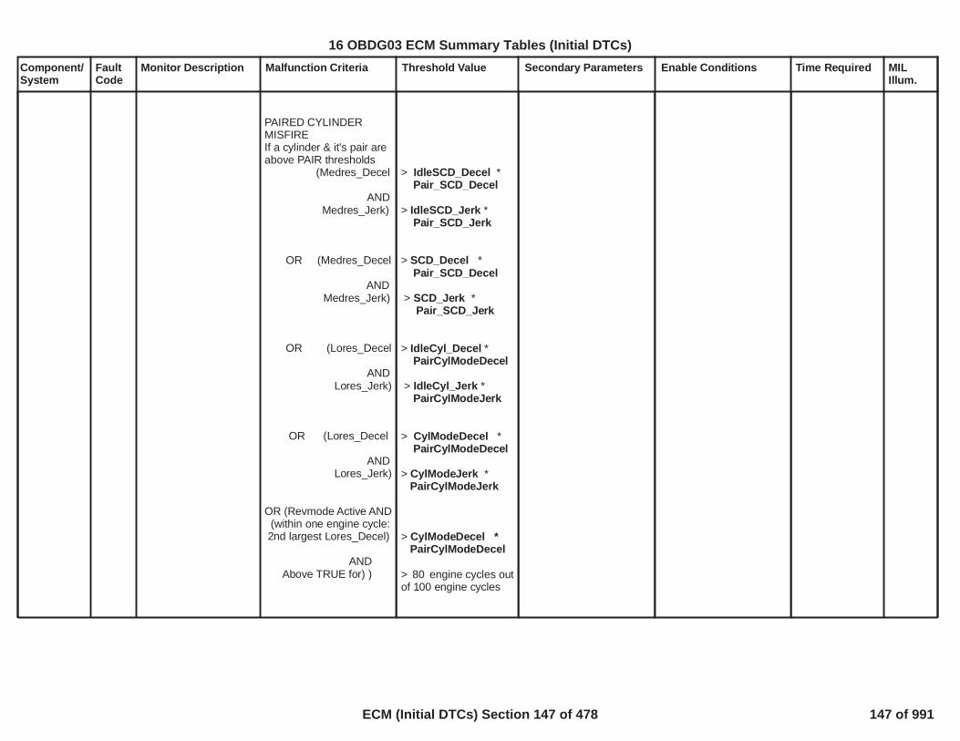
Component/System
FaultCode
Monitor Description Malfunction Criteria Threshold Value Secondary Parameters Enable Conditions Time Required MILIllum.
PAIRED CYLINDERMISFIREIf a cylinder & it's pair areabove PAIR thresholds
(Medres_Decel
ANDMedres_Jerk)
OR (Medres_Decel
ANDMedres_Jerk)
OR (Lores_Decel
ANDLores_Jerk)
OR (Lores_Decel
ANDLores_Jerk)
OR (Revmode Active AND(within one engine cycle:2nd largest Lores_Decel)
ANDAbove TRUE for) )
> *IdleSCD_DecelPair_SCD_Decel
> *IdleSCD_JerkPair_SCD_Jerk
> *SCD_DecelPair_SCD_Decel
> *SCD_JerkPair_SCD_Jerk
> *IdleCyl_DecelPairCylModeDecel
> *IdleCyl_JerkPairCylModeJerk
> *CylModeDecelPairCylModeDecel
> *CylModeJerkPairCylModeJerk
> *CylModeDecelPairCylModeDecel
> engine cycles out80of 100 engine cycles
16 OBDG03 ECM Summary Tables (Initial DTCs)
ECM (Initial DTCs) Section 147 of 478 147 of 991

Component/System
FaultCode
Monitor Description Malfunction Criteria Threshold Value Secondary Parameters Enable Conditions Time Required MILIllum.
BANK MISFIRECylinders aboveBank Thresholds
(Medres_Decel
ANDMedres_Jerk)
OR (Medres_Decel
ANDMedres_Jerk)
OR (Lores_Decel
ANDLores_Jerk)
OR (Lores_Decel
ANDLores_Jerk)
CONSECUTIVECYLINDER MISFIRE
1st cylinder usessingle cyl continuousmisfire thresholds;2nd Cylinder uses:
(Medres_Decel
>= cylinders3
> *IdleSCD_DecelBank_SCD_Decel
> *IdleSCD_JerkBank_SCD_Jerk
> *SCD_DecelBank_SCD_Decel
> *SCD_JerkBank_SCD_Jerk
> *IdleCyl_DecelBankCylModeDecel
> *IdleCyl_JerkBankCylModeJerk
> *CylModeDecelBankCylModeDecel
> *CylModeJerkBankCylModeJerk
> *IdleSCD_DecelConsecSCD_Decel
16 OBDG03 ECM Summary Tables (Initial DTCs)
ECM (Initial DTCs) Section 148 of 478 148 of 991

Component/System
FaultCode
Monitor Description Malfunction Criteria Threshold Value Secondary Parameters Enable Conditions Time Required MILIllum.
ANDMedres_Jerk)
OR (Medres_Decel
ANDMedres_Jerk)
OR (Lores_Decel
ANDLores_Jerk)
OR (Lores_Decel
ANDLores_Jerk)
CYLINDERDEACTIVATION MODE(Active Fuel Managment)
AFM: SINGLE CYLINDERCONTINUOUS MISFIRE
(CylAfterDeacCyl_Decel
ANDCylAfterDeacCyl_Jerk)
OR
> *IdleSCD_JerkConsecSCD_Jerk
> *SCD_DecelConsecSCD_Decel
> *SCD_JerkConsecSCD_Jerk
> *IdleCyl_DecelConsecCylModDecel
> *IdleSCD_JerkConsecCylModeJerk
> *CylModeDecelConsecCylModDecel
> *CylModeJerkConsecCylModeJerk
> *CylModeDecelClyAfterAFM_Decel
> *CylModeJerkCylAfterAFM_Jerk
16 OBDG03 ECM Summary Tables (Initial DTCs)
ECM (Initial DTCs) Section 149 of 478 149 of 991

Component/System
FaultCode
Monitor Description Malfunction Criteria Threshold Value Secondary Parameters Enable Conditions Time Required MILIllum.
(CylBeforeDeacCylDecel
ANDCylBeforeDeacCyl_Jerk)
AFM: RANDOM MISFIREUse random misfire
thresholds If no misfire for
(CylAfterDeacCyl_Decel
ANDCylAfterDeacCyl_Jerk)
(CylBeforeDeacCylDecel
ANDCylBeforeDeacCyl_Jerk)
Misfire Percent EmissionFailure Threshold
> *CylModeDecelCylBeforeAFM_Decel
> *CylModeJerkClyBeforeAFM_Jerk
> Engine Cycles6
> *CylModeDecel*ClyAfterAFM_Decel
RandomAFM_Decl
> *CylModeJerk*CylAfterAFM_Jerk
RandomAFM_Jerk
> *CylModeDecelCylBeforeAFM_Decel* RandomAFM_Decl
> *CylModeJerkClyBeforeAFM_Jerk
* RandomAFM_Jerk
- see details onSupporting Tables Tab
% P03002.38
16 OBDG03 ECM Summary Tables (Initial DTCs)
ECM (Initial DTCs) Section 150 of 478 150 of 991

Component/System
FaultCode
Monitor Description Malfunction Criteria Threshold Value Secondary Parameters Enable Conditions Time Required MILIllum.
Misfire Percent CatalystDamage
When engine speed andload are less than theFTP cals (3) catalystdamage exceedences areallowed.
>Catalyst_Damage_Misfire_Percentagein Supporting Tableswhenever secondaryconditions are met.
FTP rpm AND0 FTP % load0
disable conditions:
(at low speed/loads, onecylinder may not causecat damage)
Engine SpeedEngine LoadMisfire counts
Engine Speed
No active DTCs:
> rpm AND1,400> % load AND20< counts on one180cylinder
< rpm < ((Engine500Over Speed Limit) - 400
Engine speed limit is afunction of inputs likeGear and temperature
seeEngineOverSpeedLimitin supporting tables
TPS_FAEnginePowerLimitedMAF_SensorTFTKOMAP_SensorTFTKOIAT_SensorTFTKOECT_Sensor_Ckt_TFTKO5VoltReferenceB_FACrankSensor_TFTKOCrankSensor_FA
cycle delay4
cycle delay4
16 OBDG03 ECM Summary Tables (Initial DTCs)
ECM (Initial DTCs) Section 151 of 478 151 of 991

Component/System
FaultCode
Monitor Description Malfunction Criteria Threshold Value Secondary Parameters Enable Conditions Time Required MILIllum.
P0315 & engine speed
Fuel Level Low
Cam and Crank Sensors
Misfire requests TCCunlock
Fuel System Status
Active FuelManagement
Undetectable enginespeed and engine loadregion
Abusive Engine OverSpeed
Below zero torque (exceptCARB approved 3000rpm to redline triangle.)
Below zero torque:TPS
Vehicle Speed
EGR Intrusive test
CamLctnIntFACamLctnExhFACamSensorAnyLctnTFTKOAnyCamPhaser_FAAnyCamPhaser_TFTKOAmbPresDfltdStatus
> rpm1,000
LowFuelConditionDiagnosticin sync with each other
Not honored becauseTransmission in hot modeor POPD intrusivediagnostic running
Fuel Cut
Transition in progress
Undetectable regionfrom Malfunction Criteria
> rpm8,192
< ZeroTorqueEngLoadin Supporting Tables
%1> mph30
Active
cycle delay4
cycle delay500
cycle delay4
cycle delay4
cycle delay4
cycle delay0
cycle delay4
cycle delay0
cycle delay4
cycle delay4
cycle delay0
16 OBDG03 ECM Summary Tables (Initial DTCs)
ECM (Initial DTCs) Section 152 of 478 152 of 991

Component/System
FaultCode
Monitor Description Malfunction Criteria Threshold Value Secondary Parameters Enable Conditions Time Required MILIllum.
Manual Trans
Accel Pedal PositionAND Automatictransmission shift
After Fuel resumes onAutomatic shift containingFuel Cut
DRIVELINE RING FILTERAfter a low level misfire,another misfire may notbe detectable untildriveline ringing ceases.If no ringing seen, stopfilter early.
Filter Driveline ring:
Stop filter early:
ABNORMAL ENGINESPEED OSCILLATION:(checks each "misfire"candidate in 100 engineCycle test to see if it lookslike some disturbance likerough road (abnormal). )
Used Off Idle, and whilenot shifting,
TPSEngine Speed
Veh SpeedAuto Transmission
Clutch shift
> %98.00
> " " # ofRing Filterengine cycles after misfirein Supporting Tables
> " "Number of Normals# of engine cycles aftermisfire in SupportingTables tab
> %3> rpm1,000> mph3not shifting
cycle delay0
cycle delay7
Cylinder delay2
16 OBDG03 ECM Summary Tables (Initial DTCs)
ECM (Initial DTCs) Section 153 of 478 153 of 991

Component/System
FaultCode
Monitor Description Malfunction Criteria Threshold Value Secondary Parameters Enable Conditions Time Required MILIllum.
indivdual candidatedeemed abnormal ifnumber ofconsecutive deceleratingcylinders after "misfire":(Number of decels canvary with misfire detectionequation)
Consecutive decelswhile in SCD Mode
Cyl ModeRev Mode
At the end of 100 enginecycle test, the ratio ofabnormal/candidate ischecked to confirm if realmisfire is present withinthe 100 engine cycles.
abnormal candidates/total candidates
MISFIRE CRANKSHAFTPATTERNRECOGNITIONchecks each "misfire"candidate in 100 engineCycle test to see if overallcrankshaft pattern lookslike real misfire(recognized), or somedisturbance like roughroad (unrecognized).
> Abnormal SCD Mode> Abnormal Cyl Mode> Abnormal Rev Modein Supporting Tables
> ratio0.50 discard 100engine cycle test
16 OBDG03 ECM Summary Tables (Initial DTCs)
ECM (Initial DTCs) Section 154 of 478 154 of 991
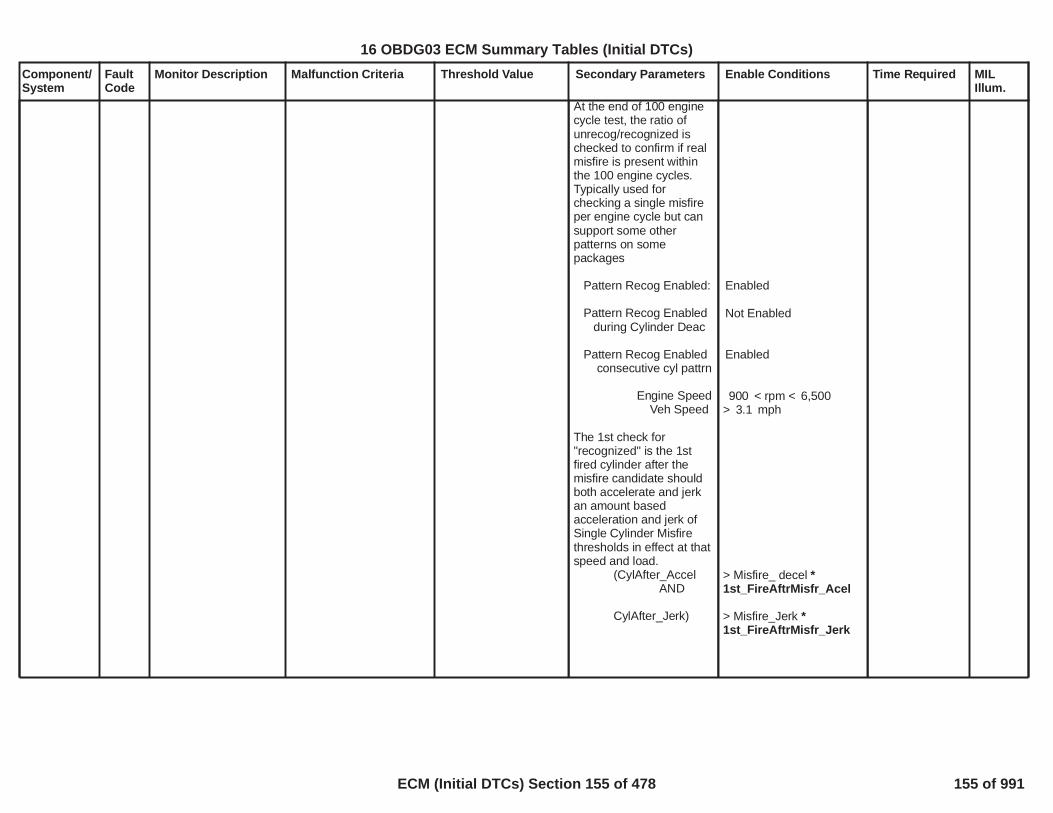
Component/System
FaultCode
Monitor Description Malfunction Criteria Threshold Value Secondary Parameters Enable Conditions Time Required MILIllum.
At the end of 100 enginecycle test, the ratio ofunrecog/recognized ischecked to confirm if realmisfire is present withinthe 100 engine cycles.Typically used forchecking a single misfireper engine cycle but cansupport some otherpatterns on somepackages
Pattern Recog Enabled:
Pattern Recog Enabledduring Cylinder Deac
Pattern Recog Enabledconsecutive cyl pattrn
Engine SpeedVeh Speed
The 1st check for"recognized" is the 1stfired cylinder after themisfire candidate shouldboth accelerate and jerkan amount basedacceleration and jerk ofSingle Cylinder Misfirethresholds in effect at thatspeed and load.
(CylAfter_AccelAND
CylAfter_Jerk)
Enabled
Not Enabled
Enabled
< rpm <900 6,500> mph3.1
> Misfire_ decel *1st_FireAftrMisfr_Acel
> Misfire_Jerk *1st_FireAftrMisfr_Jerk
16 OBDG03 ECM Summary Tables (Initial DTCs)
ECM (Initial DTCs) Section 155 of 478 155 of 991

Component/System
FaultCode
Monitor Description Malfunction Criteria Threshold Value Secondary Parameters Enable Conditions Time Required MILIllum.
Addtionally, the crankhaftis checked again a smallcalibratible number ofcylinders later to see if thedistrubance is still largelike rough road, or hascalmed down like realmisfire. The size ofdisturbance is comparedto a multiplier times theddt_jerk value used todetect misfire at thatspeed and load. If there isrepetitive misfire onconsecutive enginecycles, the expected snapis adjusted due to thehigher expecteddisturbance.
Num of Cylinders aftermisfire to start check ofcrankshaft snap
"misfire" recognized if:Crankshaft snap after:
isolated "misfire"
repetative "misfire"
At the end of 100 enginecycle test, the ratio ofunrecog/recognized ischecked to confirm if realmisfire is present.
Ratio of Unrecog/Recog
Cylinders2
< Misfire_Jerk *SnapDecayAfterMisfire
< Misfire_Jerk **SnapDecayAfterMisfire
RepetSnapDecayAdjstin Supporting Tables
> 0.80
discard 100engine cycle test
16 OBDG03 ECM Summary Tables (Initial DTCs)
ECM (Initial DTCs) Section 156 of 478 156 of 991

Component/System
FaultCode
Monitor Description Malfunction Criteria Threshold Value Secondary Parameters Enable Conditions Time Required MILIllum.
:NON-CRANKSHAFTBASED ROUGH ROAD:
Rough Road Source
IF Rough Road Source= WheelSpeedInECM
ABS/TCSWheel speed noise
VSES
IF Rough Road Source= "FromABS"
ABS/TCSRoughRoadVSES
IF Rough Road Source= "TOSS"
TOSS dispersion
AND No Active DTCs
Disabled
TOSS
active> WSSRoughRoadThresactive
activedetectedactive
>TOSSRoughRoadThresin supporting tables
Transmission OutputShaft Angular VelocityValidityTransmissionEngagedState_FA(Auto Trans only)ClutchPstnSnsr FA(Manual Trans only)
discard 100engine cycle test
discard 100engine cycle test
discard 100engine cycle test
cycle delay4
16 OBDG03 ECM Summary Tables (Initial DTCs)
ECM (Initial DTCs) Section 157 of 478 157 of 991

Component/System
FaultCode
Monitor Description Malfunction Criteria Threshold Value Secondary Parameters Enable Conditions Time Required MILIllum.
CrankshaftPositionSystemVariation NotLearned
P0315 Monitor for validcrankshaft errorcompensation factors
Sum of Compensationfactors. Each Cylinderpair shares onecompensation factor. Aperfect factor would be1.0000. Unlearnedfactors are defaulted outof range so the sum offactors would be out ofrange.
2.0040OR 1.9960
OBD ManufacturerEnable Counter
MEC = 0 seconds0.50
FrequencyContinuous100msec
Type A,1 Trips
160
16 OBDG03 ECM Summary Tables (Initial DTCs)
ECM (Initial DTCs) Section 158 of 478 158 of 991

Component/System
FaultCode
Monitor Description Malfunction Criteria Threshold Value Secondary Parameters Enable Conditions Time Required MILIllum.
KnockSensor (KS)PerformancePer Cylinder
P0324 This diagnostic checksfor knock sensorperformance out of thenormal expected rangeon a per cylinder basisdue to ExcessiveKnock (either real orfalse knock).
Enable Criteria forExcessive Knock
Excessive Knock Diag:Filtered Knock Intensity
(where 'Knock Intensity' =0 with no knock; and > 0& proportional to knockmagnitude with knock)
>P0324_PerCyl_ExcessiveKnock_Threshold(no units)
Diagnostic Enabled?
Engine Run Time
Engine Speed
Engine Air Flow
Engine CoolantTemperature
Inlet Air Temperature
Cumlative Number ofEngine Revs Above MinEng Speed (per keycycle)
Yes
seconds2.0
RPM400AND
RPM8,500
mg/cylinder400AND
mg/cylinder2,000
deg's C-40
deg's C-40
Revs400
First Order LagFilters withWeightCoefficient =0.0400
Updated eachengine event
Type B,2 Trips
161
16 OBDG03 ECM Summary Tables (Initial DTCs)
ECM (Initial DTCs) Section 159 of 478 159 of 991

Component/System
FaultCode
Monitor Description Malfunction Criteria Threshold Value Secondary Parameters Enable Conditions Time Required MILIllum.
KnockSensor (KS)Circuit Bank1
P0325 This diagnostic checksfor an open in theknock sensor circuit.
There are two possiblemethods used:
1. 20 kHz2. Normal Noise
See SupportingTables for methoddefinition:P0325_P0330_OpenMethod
Typicalimplementations:
A. Use 20 kHzmethod at all RPM(used when acceptableseparation achieved atall RPM) or
B. Use 20 kHzmethod at low/mediumRPM and Normal Noiseat high RPM
Open Circuit Methodchosen (2 possiblemethods: 20 kHz orNormal Noise):
Thresholds forOpenMethod = 20 kHZ
Filtered FFT Output
Thresholds forOpenMethod =NormalNoise:
Filtered FFT Output
Supporting Table:P0325_P0330_OpenMethod_2
(see SupportingTables)
>P0325_P0330_OpenCktThrshMin (20 kHz)AND<P0325_P0330_OpenCktThrshMax (20 kHz)
>P0325_P0330_OpenCktThrshMin (NormalNoise)AND<P0325_P0330_OpenCktThrshMax (NormalNoise)
Diagnostic Enabled?
Engine Run Time
Engine Speed
Cumulative Number ofEngine Revs (per keycycle) within min/maxEngine Speed enable(above)
Engine Air Flow
ECT
IAT
Yes
seconds2.0
RPM650and
RPM8,500
revs100
mg/cylinder40and
mg/cylinder2,000
deg's C-40
deg's C-40
First Order LagFilter with WeightCoefficient
WeightCoefficient =0.0100
Updated eachengine event
Type B,2 Trips
162
16 OBDG03 ECM Summary Tables (Initial DTCs)
ECM (Initial DTCs) Section 160 of 478 160 of 991

Component/System
FaultCode
Monitor Description Malfunction Criteria Threshold Value Secondary Parameters Enable Conditions Time Required MILIllum.
KnockSensor (KS)PerformanceBank 1
P0326 This diagnostic checksfor knock sensorperformance out of thenormal expected range,on a per sensor basis,due to Abnormal(engine) Noise
Enable Criteria for
Per Sensor AbnormalNoise Diag:
Filtered FFT Intensity:
(where 'FFT Intensity' =Non-knocking,background engine noise)
<P0326_P0331_AbnormalNoise_Threshold(Supporting Table)
Diagnostic Enabled?
Engine Run Time
Engine Speed
Engine Air Flow
Engine CoolantTemperature
Inlet Air Temperature
Individual Cylindersenabled for AbnormalNoise
Cumlative Number ofEngine Revs Above MinEng Speed (per keycycle)
Yes
seconds2.0
RPM2,000AND
RPM8,500
mg/cylinder0AND
mg/cylinder2,000
deg's C-40
deg's C-40
P0326_P0331_AbnormalNoise_CylsEnabled(Supporting Table)
Revs200
First Order LagFilters withWeightCoefficient =
0.0100
Updated eachengine event
Type B,2 Trips
163
16 OBDG03 ECM Summary Tables (Initial DTCs)
ECM (Initial DTCs) Section 161 of 478 161 of 991

Component/System
FaultCode
Monitor Description Malfunction Criteria Threshold Value Secondary Parameters Enable Conditions Time Required MILIllum.
KnockSensor (KS)Circuit LowBank 1
P0327 This diagnostic checksfor an out of range lowknock sensor signal
Sensor Input or ReturnSignal Line
< Percent8.0
(of 5 V reference)
Diagnostic Enabled?
Engine Speed
Yes
> RPM0and
< RPM8,500
Failures50out ofSamples63
100 msec rate
Type B,2 Trips
164
16 OBDG03 ECM Summary Tables (Initial DTCs)
ECM (Initial DTCs) Section 162 of 478 162 of 991

Component/System
FaultCode
Monitor Description Malfunction Criteria Threshold Value Secondary Parameters Enable Conditions Time Required MILIllum.
KnockSensor (KS)Circuit HighBank 1
P0328 This diagnostic checksfor an out of range highknock sensor signal
Sensor Input or ReturnSignal Line
> Percent39.0
(of 5 Volt Reference)
Diagnostic Enabled?
Engine Speed
Yes
> RPM0and
< RPM8,500
Failures50out ofSamples63
100 msec rate
Type B,2 Trips
165
16 OBDG03 ECM Summary Tables (Initial DTCs)
ECM (Initial DTCs) Section 163 of 478 163 of 991

Component/System
FaultCode
Monitor Description Malfunction Criteria Threshold Value Secondary Parameters Enable Conditions Time Required MILIllum.
KnockSensor (KS)Circuit Bank2
P0330 This diagnostic checksfor an open in theknock sensor circuit
There are two possiblemethods used:
1. 20 kHz2. Normal Noise
See SupportingTables for methoddefinition:P0325_P0330_OpenMethod
Typicalimplementations:
A. Use 20 kHzmethod at all RPM(used when acceptableseparation achieved atall RPM) or
B. Use 20 kHzmethod at low/mediumRPM and Normal Noiseat high RPM
Open Circuit Methodchosen (2 possiblemethods: 20 kHz orNormal Noise):
Thresholds forOpenMethod = 20 kHZ
Filtered FFT Output
Thresholds forOpenMethod =NormalNoise:
Filtered FFT Output
Supporting Table:P0325_P0330_OpenMethod_2
(See SupportingTables )
>P0325_P0330_OpenCktThrshMin (20 kHz)AND<P0325_P0330_OpenCktThrshMax (20 kHz)
>P0325_P0330_OpenCktThrshMin (NormalNoise)AND<P0325_P0330_OpenCktThrshMax (NormalNoise)
Diagnostic Enabled?
Engine Run Time
Engine Speed
Cumlative Number ofEngine Revs (per keycycle) within min/maxEngine Speed enable(above)
Engine Air Flow
ECT
IAT
Yes
seconds2.0
RPM650and
RPM8,500
> revs100
mg/cylinder40and
mg/cylinder2,000
deg's C-40
deg's C-40
First Order LagFilter with WeightCoefficient
WeightCoefficient =0.0100
Updated eachengine event
Type B,2 Trips
166
16 OBDG03 ECM Summary Tables (Initial DTCs)
ECM (Initial DTCs) Section 164 of 478 164 of 991

Component/System
FaultCode
Monitor Description Malfunction Criteria Threshold Value Secondary Parameters Enable Conditions Time Required MILIllum.
KnockSensor (KS)PerformanceBank 2
P0331 This diagnostic checksfor knock sensorperformance out of thenormal expected range,on a per sensor basis,due to Abnormal(engine) Noise
Enable Criteria for
Per Sensor AbnormalNoise Diag:
Filtered FFT Intensity:
(where 'FFT Intensity' =Non-knocking,background engine noise)
<P0326_P0331_AbnormalNoise_Threshold(Supporting Table)
Diagnostic Enabled?
Engine Run Time
Engine Speed
Engine Air Flow
Engine CoolantTemperature
Inlet Air Temperature
Individual Cylindersenabled for AbnormalNoise
Cumlative Number ofEngine Revs Above MinEng Speed (per keycycle)
Yes
seconds2.0
RPM2,000AND
RPM8,500
mg/cylinder0AND
mg/cylinder2,000
deg's C-40
deg's C-40
P0326_P0331_AbnormalNoise_CylsEnabled(Supporting Table)
Revs200
First Order LagFilters withWeightCoefficient =
0.0100
Updated eachengine event
Type B,2 Trips
167
16 OBDG03 ECM Summary Tables (Initial DTCs)
ECM (Initial DTCs) Section 165 of 478 165 of 991

Component/System
FaultCode
Monitor Description Malfunction Criteria Threshold Value Secondary Parameters Enable Conditions Time Required MILIllum.
KnockSensor (KS)Circuit LowBank 2
P0332 This diagnostic checksfor an out of range lowknock sensor signal
Sensor Input or ReturnSignal Line
< Percent8.0
(of 5 Volt Reference)
Diagnostic Enabled?
Engine Speed
Yes
> RPM0and
< RPM8,500
Failures50out ofSamples63
100 msec rate
Type B,2 Trips
168
16 OBDG03 ECM Summary Tables (Initial DTCs)
ECM (Initial DTCs) Section 166 of 478 166 of 991

Component/System
FaultCode
Monitor Description Malfunction Criteria Threshold Value Secondary Parameters Enable Conditions Time Required MILIllum.
KnockSensor (KS)Circuit HighBank 2
P0333 This diagnostic checksfor an out of range highknock sensor signal
Sensor Input or ReturnSignal Line
> Percent39.00
(of 5 Volt Reference)
Diagnostic Enabled?
Engine Speed
Yes
> RPM0and
< RPM8,500
Failures50out ofSamples63
100 msec rate
Type B,2 Trips
169
16 OBDG03 ECM Summary Tables (Initial DTCs)
ECM (Initial DTCs) Section 167 of 478 167 of 991

Component/System
FaultCode
Monitor Description Malfunction Criteria Threshold Value Secondary Parameters Enable Conditions Time Required MILIllum.
Time since last crankshaftposition sensor pulsereceived >= seconds4.0
Starter engagedAND(cam pulses beingreceivedOR( MAF_SensorFAANDEngine Air Flow
= FALSE
> grams/second ) )3.0
Continuousevery 100 msec
CrankshaftPosition(CKP)Sensor ACircuit
P0335 Determines if a faultexists with the crankposition sensor signal
Type B,2 Trips
No crankshaft pulsesreceived >= seconds1.0
Engine is Running
Starter is not engaged
Continuousevery 12.5 msec
No crankshaft pulsesreceived
Engine is RunningORStarter is engaged
No DTC Active: P0365P0366
failures out2of samples10
One sample perengine revolution
170
16 OBDG03 ECM Summary Tables (Initial DTCs)
ECM (Initial DTCs) Section 168 of 478 168 of 991
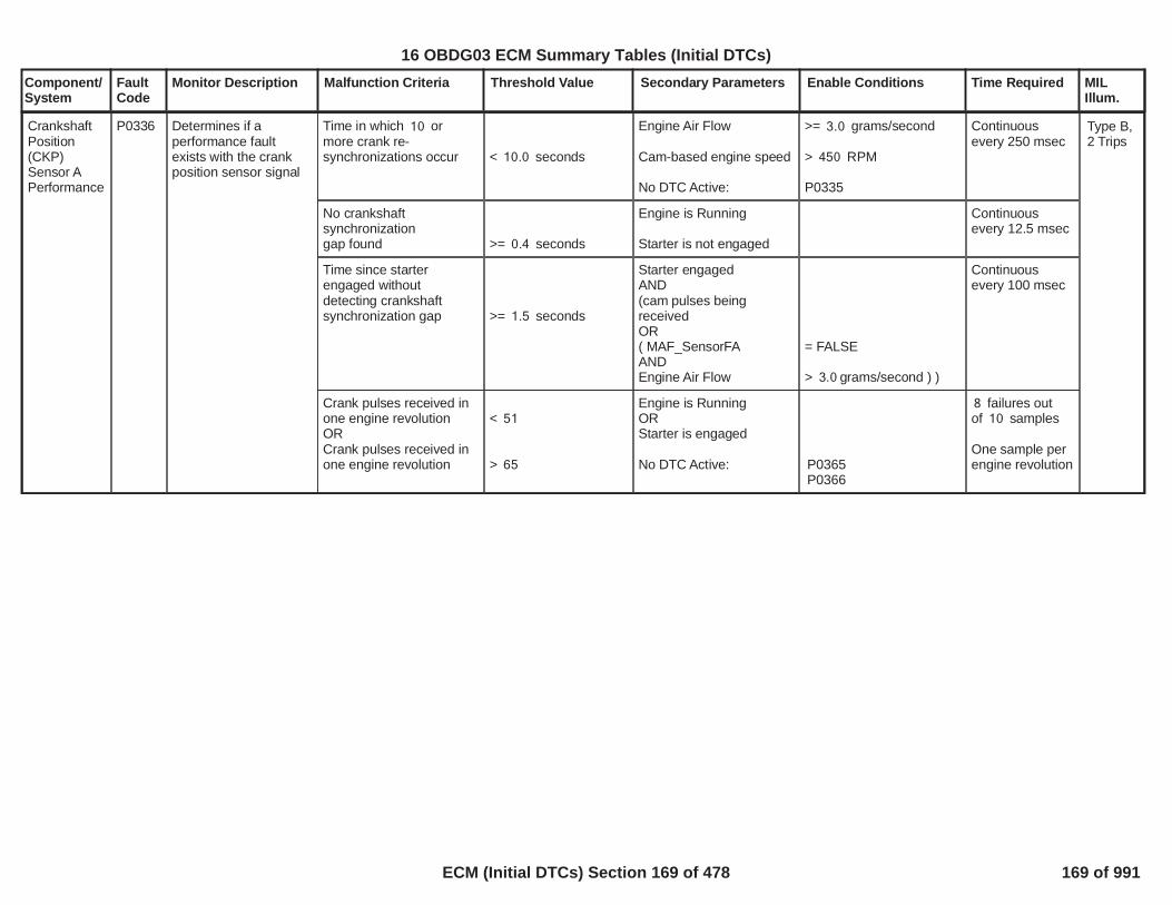
Component/System
FaultCode
Monitor Description Malfunction Criteria Threshold Value Secondary Parameters Enable Conditions Time Required MILIllum.
Time in which or10more crank re-synchronizations occur < seconds10.0
Engine Air Flow
Cam-based engine speed
No DTC Active:
>= grams/second3.0
> RPM450
P0335
Continuousevery 250 msec
CrankshaftPosition(CKP)Sensor APerformance
P0336 Determines if aperformance faultexists with the crankposition sensor signal
Type B,2 Trips
No crankshaftsynchronizationgap found >= seconds0.4
Engine is Running
Starter is not engaged
Continuousevery 12.5 msec
Time since starterengaged withoutdetecting crankshaftsynchronization gap >= seconds1.5
Starter engagedAND(cam pulses beingreceivedOR( MAF_SensorFAANDEngine Air Flow
= FALSE
> grams/second ) )3.0
Continuousevery 100 msec
Crank pulses received inone engine revolutionORCrank pulses received inone engine revolution
< 51
> 65
Engine is RunningORStarter is engaged
No DTC Active: P0365P0366
failures out8of samples10
One sample perengine revolution
171
16 OBDG03 ECM Summary Tables (Initial DTCs)
ECM (Initial DTCs) Section 169 of 478 169 of 991

Component/System
FaultCode
Monitor Description Malfunction Criteria Threshold Value Secondary Parameters Enable Conditions Time Required MILIllum.
Time since last camshaftposition sensor pulsereceived
OR
Time that starter has beenengaged without acamshaft sensor pulse
>= seconds5.5
>= seconds4.0
Starter engagedAND(crank pulses beingreceivedOR( MAF_SensorFAANDEngine Air Flow
= FALSE
> grams/second ) )3.0
Continuousevery 100 msec
CamshaftPosition(CMP)SensorCircuit Bank1 Sensor A
P0340 Determines if a faultexists with the camposition bank 1 sensorA signal
Type B,2 Trips
Fewer than camshaft4pulses received in a time > seconds3.0
Engine is running
Starter is not engaged
Continuousevery 100 msec
No camshaft pulsesreceived during first
MEDRES events12(There are 12MEDRES events perengine cycle
Crankshaft issynchronized
Starter must beengaged to enable thediagnostic, but thediagnostic will notdisable when thestarter is disengaged
No DTC Active: CrankSensor_FA
Continuousevery MEDRESevent
The number of camshaftpulses received during
engine cycles100 = 0
Crankshaft issynchronized
No DTC Active: CrankSensor_FA
failures out of8samples10
Continuousevery enginecycle
172
16 OBDG03 ECM Summary Tables (Initial DTCs)
ECM (Initial DTCs) Section 170 of 478 170 of 991

Component/System
FaultCode
Monitor Description Malfunction Criteria Threshold Value Secondary Parameters Enable Conditions Time Required MILIllum.
The number of camshaftpulses received duringfirst MEDRES events12isOR
(There are 12MEDRES events perengine cycle)
< 4> 10
Crankshaft issynchronized
Starter must be engagedto enable the diagnostic,but the diagnostic willnot disable when thestarter is disengaged
No DTC Active: CrankSensor_FA
Continuousevery MEDRESevent
CamshaftPosition(CMP)SensorPerformanceBank 1Sensor A
P0341 Determines if aperformance faultexists with the camposition bank 1 sensorA signal
Type B,2 Trips
The number of camshaftpulses received during
engine cycles100OR
< 398> 402
Crankshaft issynchronized
No DTC Active: CrankSensor_FA
failures out of8samples10
Continuousevery enginecycle
173
16 OBDG03 ECM Summary Tables (Initial DTCs)
ECM (Initial DTCs) Section 171 of 478 171 of 991

Component/System
FaultCode
Monitor Description Malfunction Criteria Threshold Value Secondary Parameters Enable Conditions Time Required MILIllum.
Crankshaft position isin error by a number ofcrankshaft wheel teeth > crankshaft teeth2
Engine has startedrotating during ahybrid auto-start
Crankshaft position isbeing verified
No Active DTCs: CrankSensor_FA
failures out of2samples3
a sample occurseach time theengine is started
CrankshaftPositionSensor -CrankshaftStartPositionIncorrect
P034A Monitors the position ofthe crankshaft during ahybrid auto-start toverify that the sensorhas reported thecrankshaft positionproperly.
Type B,2 Trips
Crankshaft position isin error by at least onecrankshaft wheel tooth
Engine has startedrotating during ahybrid auto-start
Crankshaft position isbeing verified
No Active DTCs: CrankSensor_FA
failures out of4samples5
a sample occurseach time theengine is started
174
16 OBDG03 ECM Summary Tables (Initial DTCs)
ECM (Initial DTCs) Section 172 of 478 172 of 991

Component/System
FaultCode
Monitor Description Malfunction Criteria Threshold Value Secondary Parameters Enable Conditions Time Required MILIllum.
CrankshaftPositionSensor -CrankshaftDirectionIncorrect
P034B The CrankshaftDirection Incorrect testmonitors the number ofcrankshaft reversalsreported by a bi-directional cranksensor.
Number of crankshaftsensor reversals
within a period of time
>= 3
<= seconds10.0
Engine SpeedEngine SpeedEngine Air Flow
Engine MovementDetected
No Active DTCs:
> RPM400< RPM2,000>= grams/second3.0
CrankSensor_FA
Continuous
Every 250 msec
Type B,2 Trips
175
16 OBDG03 ECM Summary Tables (Initial DTCs)
ECM (Initial DTCs) Section 173 of 478 173 of 991

Component/System
FaultCode
Monitor Description Malfunction Criteria Threshold Value Secondary Parameters Enable Conditions Time Required MILIllum.
IGNITIONCONTROL#1 CIRCUIT
P0351 Diagnoses Cylinder #1Ignition Control (EST)output driver circuit foran Open Circuit fault.
The ECM detects there ishigh impedance on theEST circuit.
> 30 k impedancebetween signal andcontroller ground
Engine cranking orrunning
Ignition Voltage > Volts5.00
Failures50out ofSamples63
250 msec rate
Type B,2 Trips
176
16 OBDG03 ECM Summary Tables (Initial DTCs)
ECM (Initial DTCs) Section 174 of 478 174 of 991

Component/System
FaultCode
Monitor Description Malfunction Criteria Threshold Value Secondary Parameters Enable Conditions Time Required MILIllum.
IGNITIONCONTROL#2 CIRCUIT
P0352 Diagnoses Cylinder #2Ignition Control (EST)output driver circuit foran Open Circuit fault.
High impedance duringdriver high state (indicatesopen circuit)
>30 k impedancebetween signal andcontroller ground
Engine running
Ignition Voltage > Volts11.0
Failures50
out ofSamples63
100 msec rate
Type B,2 Trips
177
16 OBDG03 ECM Summary Tables (Initial DTCs)
ECM (Initial DTCs) Section 175 of 478 175 of 991
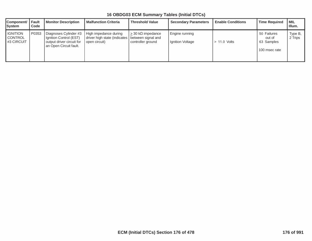
Component/System
FaultCode
Monitor Description Malfunction Criteria Threshold Value Secondary Parameters Enable Conditions Time Required MILIllum.
IGNITIONCONTROL#3 CIRCUIT
P0353 Diagnoses Cylinder #3Ignition Control (EST)output driver circuit foran Open Circuit fault.
High impedance duringdriver high state (indicatesopen circuit)
> 30 k impedancebetween signal andcontroller ground
Engine running
Ignition Voltage > Volts11.0
Failures50out ofSamples63
100 msec rate
Type B,2 Trips
178
16 OBDG03 ECM Summary Tables (Initial DTCs)
ECM (Initial DTCs) Section 176 of 478 176 of 991

Component/System
FaultCode
Monitor Description Malfunction Criteria Threshold Value Secondary Parameters Enable Conditions Time Required MILIllum.
IGNITIONCONTROL#4 CIRCUIT
P0354 Diagnoses Cylinder #4Ignition Control (EST)output driver circuit foran Open Circuit fault.
High impedance duringdriver high state (indicatesopen circuit)
> 30 k impedancebetween signal andcontroller ground
Engine running
Ignition Voltage > Volts11.0
Failures50out ofSamples63
100 msec rate
Type B,2 Trips
179
16 OBDG03 ECM Summary Tables (Initial DTCs)
ECM (Initial DTCs) Section 177 of 478 177 of 991

Component/System
FaultCode
Monitor Description Malfunction Criteria Threshold Value Secondary Parameters Enable Conditions Time Required MILIllum.
Time since last camshaftposition sensor pulsereceived
OR
Time that starter has beenengaged without acamshaft sensor pulse
>= seconds5.5
>= seconds4.0
Starter engagedAND(crank pulses beingreceivedOR( MAF_SensorFAANDEngine Air Flow
= FALSE
> grams/second ) )3.0
Continuousevery 100 msec
CamshaftPosition(CMP)SensorCircuit Bank1 Sensor B
P0365 Determines if a faultexists with the camposition bank 1 sensorB signal
Type B,2 Trips
Fewer than camshaft4pulses received in a time > seconds3.0
Engine is running
Starter is not engaged
Continuousevery 100 msec
No camshaft pulsesreceived during first
MEDRES events12(There are 12MEDRES events perengine cycle
Crankshaft issynchronized
Starter must beengaged to enable thediagnostic, but thediagnostic will notdisable when thestarter is disengaged
No DTC Active: CrankSensor_FA
Continuousevery MEDRESevent
The number of camshaftpulses received during
engine cycles100 = 0
Crankshaft issynchronized
No DTC Active: CrankSensor_FA
failures out of8samples10
Continuousevery enginecycle
180
16 OBDG03 ECM Summary Tables (Initial DTCs)
ECM (Initial DTCs) Section 178 of 478 178 of 991

Component/System
FaultCode
Monitor Description Malfunction Criteria Threshold Value Secondary Parameters Enable Conditions Time Required MILIllum.
The number of camshaftpulses received duringfirst MEDRES events12isOR
(There are 12MEDRES events perengine cycle)
< 4> 10
Crankshaft issynchronized
Starter must be engagedto enable the diagnostic,but the diagnostic willnot disable when thestarter is disengaged
No DTC Active: CrankSensor_FA
Continuousevery MEDRESevent
CamshaftPosition(CMP)SensorPerformanceBank 1Sensor B
P0366 Determines if aperformance faultexists with the camposition bank 1 sensorB signal
Type B,2 Trips
The number of camshaftpulses received during
engine cycles100OR
< 398> 402
Crankshaft issynchronized
No DTC Active: CrankSensor_FA
failures out of8samples10
Continuousevery enginecycle
181
16 OBDG03 ECM Summary Tables (Initial DTCs)
ECM (Initial DTCs) Section 179 of 478 179 of 991

Component/System
FaultCode
Monitor Description Malfunction Criteria Threshold Value Secondary Parameters Enable Conditions Time Required MILIllum.
CatalystSystem LowEfficiencyBank 1
P0420 NOTE: The informationbelow applies toapplications that usethe Decel CatalystMonitor Algorithm
Oxygen Storage. Thecatalyst washcoatcontains Cerium Oxide.Cerium Oxide reactswith NO and O2 duringlean A/F excursions tostore the excessoxygen (I.e. CeriumOxidation). During richA/F excursions, CeriumOxide reacts with COand H2 to release thisstored oxygen (I.e.Cerium Reduction).This is referred to asthe Oxygen StorageCapacity, or OSC.CatMon’s strategy is to“measure” the OSC ofthe catalyst throughforced Rich (intrusiverich) and Lean (decelfuel cutoff) A/Fexcursions
Normalized Ratio OSCValue CalculationInformation andDefinitions =1. Raw OSCCalculation = (post catO2 Resp time - pre catO2 Resp time)2. BestFailing OSCvalue from a calibration
Normalized Ratio OSCValue(EWMA filtered)
< 0.35 All enable criteriaassociated with P0420can be found underP2270 - (O2 SensorSignal Stuck Lean Bank 1Sensor 2)
Rapid Step Response(RSR) feature will initiatemultiple tests:
If the difference betweencurrent EWMA value andthe current OSCNormalized Ratio value is
and the current OSCNormalized Ratio value is
Maximum number of RSRtests to detect failurewhen RSR is enabled.
Front O2 SensororFront WRAF
Rear O2 Sensor
General Enable Criteria
In addition to the p-codeslisted under P2270, thefollowing DTC's shall alsonot be set:
For switching O2 sensors:
> 0.63
< 0.18
12
> mV825.00or> EQR1.08
> mV825.00
O2S_Bank_1_Sensor_1_FA
1 test attemptedper valid decelperiod
Minimum of 1test per trip
Maximum of4tests per trip
Frequency:Fueling Related :12.5 ms
OSCMeasurements:100 ms
Temp Prediction:12.5ms
Type A,1 Trips
182
16 OBDG03 ECM Summary Tables (Initial DTCs)
ECM (Initial DTCs) Section 180 of 478 180 of 991
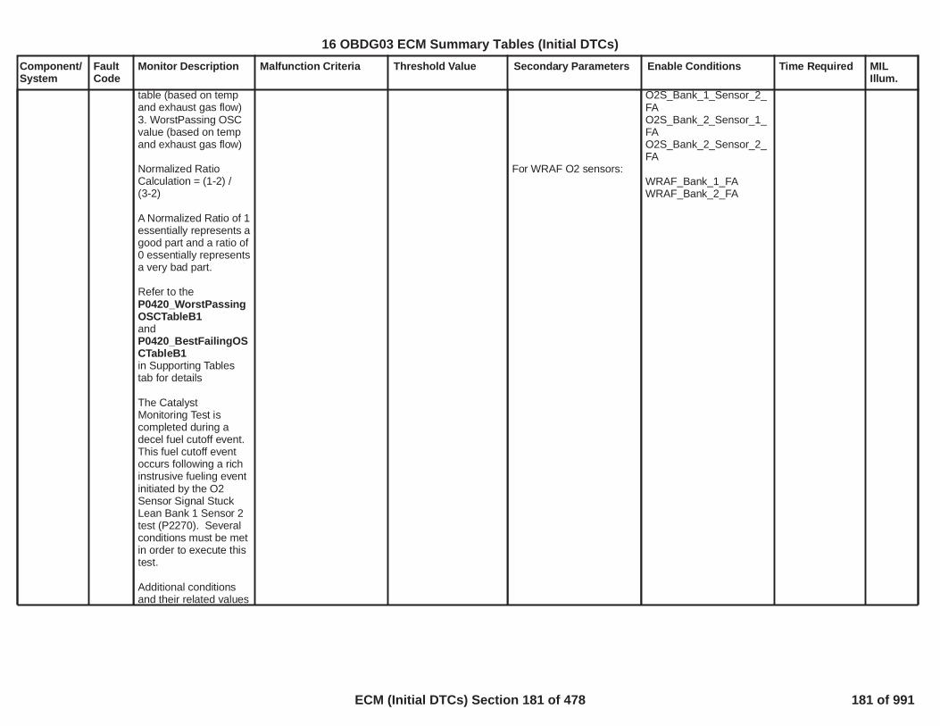
Component/System
FaultCode
Monitor Description Malfunction Criteria Threshold Value Secondary Parameters Enable Conditions Time Required MILIllum.
table (based on tempand exhaust gas flow)3. WorstPassing OSCvalue (based on tempand exhaust gas flow)
Normalized RatioCalculation = (1-2) /(3-2)
A Normalized Ratio of 1essentially represents agood part and a ratio of0 essentially representsa very bad part.
Refer to theP0420_WorstPassingOSCTableB1andP0420_BestFailingOSCTableB1in Supporting Tablestab for details
The CatalystMonitoring Test iscompleted during adecel fuel cutoff event.This fuel cutoff eventoccurs following a richinstrusive fueling eventinitiated by the O2Sensor Signal StuckLean Bank 1 Sensor 2test (P2270). Severalconditions must be metin order to execute thistest.
Additional conditionsand their related values
For WRAF O2 sensors:
O2S_Bank_1_Sensor_2_FAO2S_Bank_2_Sensor_1_FAO2S_Bank_2_Sensor_2_FA
WRAF_Bank_1_FAWRAF_Bank_2_FA
183
16 OBDG03 ECM Summary Tables (Initial DTCs)
ECM (Initial DTCs) Section 181 of 478 181 of 991

Component/System
FaultCode
Monitor Description Malfunction Criteria Threshold Value Secondary Parameters Enable Conditions Time Required MILIllum.
are listed in the"SecondaryParameters" and"Enable Conditions"section of thisdocument for P2270(O2 Sensor SignalStuck Lean Bank 1Sensor 2)
184
16 OBDG03 ECM Summary Tables (Initial DTCs)
ECM (Initial DTCs) Section 182 of 478 182 of 991

Component/System
FaultCode
Monitor Description Malfunction Criteria Threshold Value Secondary Parameters Enable Conditions Time Required MILIllum.
EvaporativeEmission(EVAP)SystemSmall LeakDetected
(No ELCP -ConventionalEVAPDiagnosticwith EATusing OATSensor)
P0442 This DTC will detect asmall leak ( 0.020”) inthe EVAP systembetween the fuel fill capand the purge solenoid.On some applications asmall leak is defined as 0.025”, 0.030”, or
0.150”. The engine offnatural vacuum method(EONV) is used.EONV is anevaporative systemleak detectiondiagnostic that runswhen the vehicle isshut off when enableconditions are met.Prior to sealing thesystem and performingthe diagnostic, the fuelvolatility is analyzed. Inan open system(Canister Vent Solenoid[CVS] open) highvolatility fuel createsenough flow togenerate a measurablepressure differentialrelative toatmospheric.After thevolatility check, thevent solenoid will close.After the vent is closed,typically a build up ofpressure from the hotsoak begins (phase-1).The pressure typicallywill peak and thenbegin to decrease asthe fuel cools. When
The total delta from peakpressure to peak vacuumduring the test isnormalized against acalibration pressurethreshold table that isbased upon fuel level andambient temperature.(Please see
in
P0442 EONV PressureThreshold (Pascals)TableSupporting Tables). Thenormalized value iscalculated by the followingequation: 1 - (peakpressure - peak vacuum) /pressure threshold. Thenormalized value isentered into EWMA (with0= perfect pass and 1=perfect fail).
When EWMA is
the DTC light isilluminated.
The DTC light can beturned off if the EWMA is
and stays below theEWMA fail threshold for 3additional consecutivetrips.
> (EWMA Fail0.56Threshold),
(EWMA Re-0.35Pass Threshold)
Fuel LevelDrive TimeDrive lengthECTBaroDistance since assemblyplantEngine not run timebefore key off must be
Time since last completetestif normalized result andEWMA is passing
ORTime since last completetestif normalized result orEWMA is failing
Estimated AmbientTemperature (EAT) usingOAT sensor at end ofdrive
Conditions for EstimatedAmbient TemperatureUsing OAT Sensor to beValid******************************1. Startup OAT is lessthan previous trip EAT
OR
% Percent %10 90seconds600miles5.0
°C63 kPa70
miles10.0
refer toP0442 Engine Off TimeBefore Vehicle OffMaximum as a Functionof Estimated AmbientTemperature Tablein Supporting Tables.
hours17
hours10
°C Temperature °C0 34
******************************
Once per trip,during hot soak(up to2,400sec.). No morethan 2unsuccessfulattemptsbetweencompleted tests.
Type A,1 Trips
EWMA
Averagerunlength is8 to 12tripsundernormalconditions
Runlength is3 to 6tripsaftercodeclear ornon-volatilereset
185
16 OBDG03 ECM Summary Tables (Initial DTCs)
ECM (Initial DTCs) Section 183 of 478 183 of 991

Component/System
FaultCode
Monitor Description Malfunction Criteria Threshold Value Secondary Parameters Enable Conditions Time Required MILIllum.
the pressure drops( ) Pa from peak-62pressure, the vent isthen opened for 60seconds to normalizethe system pressure.The vent is againclosed to begin thevacuum portion of thetest (phase-2). As thefuel temperaturecontinues to fall, avacuum will beginforming. The vacuumwill continue until itreaches a vacuumpeak. When thepressure rises
Pa from vacuum62peak, the test thencompletes. If the key isturned on while thediagnostic test is inprogress, the test willabort.
2. Startup ECT - previoustrip EAT
OR3. Engine off time
OR4. At startup, time sinceprevious EAT valid andable to learn
OR5. EAT - current OAT
OR6. EAT < current OATand speed timerand current OAT - EAT
Speed timer increments at100 msec rate andincrements vary based onvehicle speed as follows:
vehicle speed < mph19mph<speed< mph19 53mph<speed<53 124mph<speed<124 124
Speed timer can never beless than 0 seconds
******************************1. High Fuel Volatility
During the volatilityphase, pressure in thefuel tank is integrated vs.volatility time. If theintegrated pressure isthen test aborts andunsuccessful attempts is
°C0
seconds9,000
seconds3,600
0 °C difference °C2
seconds260 °C2
- seconds10.0seconds0.13seconds0.20seconds1.00
******************************
< -5
186
16 OBDG03 ECM Summary Tables (Initial DTCs)
ECM (Initial DTCs) Section 184 of 478 184 of 991

Component/System
FaultCode
Monitor Description Malfunction Criteria Threshold Value Secondary Parameters Enable Conditions Time Required MILIllum.
incremented. This valueequates to an averageintegrated fuel tankpressure > Pa.1,245Please seeP0442 Volatility Time asa Function of Estimateof Ambient Temperaturein Supporting Tables.
OR2. Vacuum RefuelingDetected
See P0454 Fault Code forinformation on vacuumrefueling algorithm.
OR3. Fuel Level RefuelingDetected
See P0464 Fault Code forinformation on fuel levelrefueling.
OR4. Vacuum Out of Rangeand No Refueling
See P0451 Fault Code forinformation on vacuumsensor out of range andP0464 Fault Code forinformation on fuel levelrefueling.
OR5. Vacuum Out of Rangeand Refueling Detected
See P0451 Fault Code for
187
16 OBDG03 ECM Summary Tables (Initial DTCs)
ECM (Initial DTCs) Section 185 of 478 185 of 991
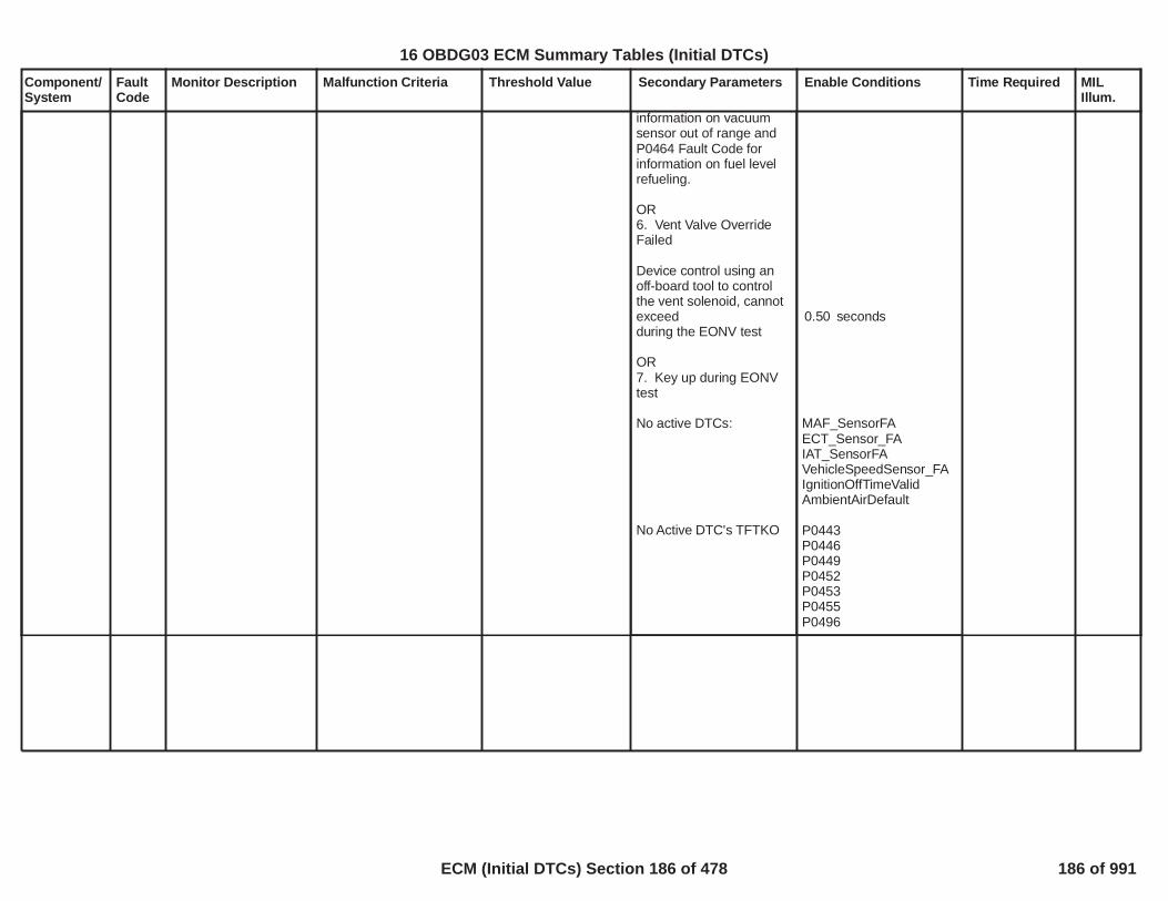
Component/System
FaultCode
Monitor Description Malfunction Criteria Threshold Value Secondary Parameters Enable Conditions Time Required MILIllum.
information on vacuumsensor out of range andP0464 Fault Code forinformation on fuel levelrefueling.
OR6. Vent Valve OverrideFailed
Device control using anoff-board tool to controlthe vent solenoid, cannotexceedduring the EONV test
OR7. Key up during EONVtest
No active DTCs:
No Active DTC's TFTKO
seconds0.50
MAF_SensorFAECT_Sensor_FAIAT_SensorFAVehicleSpeedSensor_FAIgnitionOffTimeValidAmbientAirDefault
P0443P0446P0449P0452P0453P0455P0496
188
16 OBDG03 ECM Summary Tables (Initial DTCs)
ECM (Initial DTCs) Section 186 of 478 186 of 991

Component/System
FaultCode
Monitor Description Malfunction Criteria Threshold Value Secondary Parameters Enable Conditions Time Required MILIllum.
EvaporativeEmission(EVAP)CanisterPurgeSolenoidValve Circuit(ODM)
(No ELCP -ConventionalEVAPDiagnostic -For 3 DTCImplementation Only)
P0443 Diagnoses the canisterpurge solenoid low sidedriver circuit for circuitfaults
Voltage low during driveroff state (indicates opencircuit)
Open circuit: 200 K impedence
between signal andcontroller ground
PT Relay Voltage Voltage volts11.0 failures out of20samples25
250 ms / sample
Type B,2 Trips
Note: Incertaincontrollers P0458may alsoset(Canister PurgeSolenoidShort toGround)
189
16 OBDG03 ECM Summary Tables (Initial DTCs)
ECM (Initial DTCs) Section 187 of 478 187 of 991

Component/System
FaultCode
Monitor Description Malfunction Criteria Threshold Value Secondary Parameters Enable Conditions Time Required MILIllum.
EvaporativeEmission(EVAP) VentSystemPerformance
(No ELCP -ConventionalEVAPDiagnostic)
P0446 This DTC willdetermine if arestriction is present inthe vent solenoid, ventfiller, vent hose orEVAP canister.
This test runs withnormal purge and ventvalve is open.
Vent Restriction PrepTest:Vented VacuumforORVented Vacuumfor
Vent Restriction Test:Tank Vacuumforbefore Purge Volume
After setting the DTC forthe first time, liters of2fuel must be consumedbefore setting the DTC forthe second time.
< Pa-623seconds60
> Pa1,245seconds60
> Pa2,989seconds5liters6
Fuel LevelSystem Voltage
Startup IAT
Startup ECTBARO
No active DTCs:
No Active DTC's TFTKO
% Percent %10 90volts Voltage 11 32
volts°C Temperature 4 34
°C °C35 kPa70
MAP_SensorFA TPS_FAVehicleSpeedSensor_FAIAT_SensorFAECT_Sensor_FAAmbientAirDefaultEnginePowerLimited
P0443P0449P0452P0453P0454
Once per ColdStart
Time isdependent ondrivingconditions
Maximum timebefore test abortis seconds1,000
Type B,2 Trips
190
16 OBDG03 ECM Summary Tables (Initial DTCs)
ECM (Initial DTCs) Section 188 of 478 188 of 991

Component/System
FaultCode
Monitor Description Malfunction Criteria Threshold Value Secondary Parameters Enable Conditions Time Required MILIllum.
EvaporativeEmission(EVAP) VentSolenoidControlCircuit(ODM)
(No ELCP -ConventionalEVAPDiagnostic -For 3 DTCImplementation Only)
P0449 Diagnoses the ventsolenoid low side drivercircuit for circuit faults.
Voltage low during driveroff state (indicates opencircuit)
Open circuit: 200 K impedence
between signal andcontroller ground
failures out of20samples25
250 ms / sample
Type B,2 Trips
Note: Incertaincontrollers P0498may alsoset (VentSolenoidShort toGround)
191
16 OBDG03 ECM Summary Tables (Initial DTCs)
ECM (Initial DTCs) Section 189 of 478 189 of 991

Component/System
FaultCode
Monitor Description Malfunction Criteria Threshold Value Secondary Parameters Enable Conditions Time Required MILIllum.
Fuel TankPressure(FTP)SensorCircuitPerformance
(No ELCP -ConventionalEVAPDiagnostic)
P0451 The DTC will be set ifthe fuel tank vacuumsensor is out of rangewhen it tries to re-zeroprior to the phase-1 orphase-2 portions of theengine-off naturalvacuum small leak test.
The tank vacuum sensorvoltage is compared to awindow about the nominalsensor voltage offset(~1.5 volts)
Upper voltage threshold(voltage addition abovethe nominal voltage)
Lower voltage threshold(voltage subtraction belowthe nominal voltage)
The difference betweentank vacuum sensorvoltage and the nominaloffset voltage is thennormalized against theappropriate thresholdlisted above to produce aratio between 0.0 and 1.0.This normalized re-zeroratio is then filtered with aEWMA (with 0= perfectpass and 1=perfect fail).
When EWMA is
the DTC light isilluminated.
The DTC light can beturned off if the EWMA is
and stays below theEWMA fail threshold for 3additional consecutivetrips.
volts0.2
volts0.2
> (EWMA Fail0.73Threshold),
(EWMA Re-Pass0.40Threshold)
This test will executewhenever the engine-offnatural vacuum small leaktest (P0442) executes
This test isexecuted duringan engine-offnatural vacuumsmall leak test.The number oftimes that itexecutes canrange from zeroto two perengine-offperiod.Thelength of the testis determined bythe refuelingrationality test,which can takeup to 600seconds tocomplete.
Type A,1 Trips
EWMA
Averagerunlength:6Runlength is2 tripsaftercodeclear ornon-volatilereset
192
16 OBDG03 ECM Summary Tables (Initial DTCs)
ECM (Initial DTCs) Section 190 of 478 190 of 991

Component/System
FaultCode
Monitor Description Malfunction Criteria Threshold Value Secondary Parameters Enable Conditions Time Required MILIllum.
Fuel TankPressure(FTP)SensorCircuit LowVoltage
(No ELCP -ConventionalEVAPDiagnostic)
P0452 This DTC will detect aFuel Tank Pressure(FTP) sensor signalthat is too low out ofrange.
FTP sensor signal
The normal operatingrange of the FTP sensoris 0.5 volts (~1245 Pa) to4.5 volts(~ -3736 Pa).
< volts ( % of0.15 3.0Vref or ~ Pa)1,681
Time delay after sensorpower up for sensorwarm-up is seconds0.10
failures out640of samples800
12.5 ms / sample
Type B,2 Trips
193
16 OBDG03 ECM Summary Tables (Initial DTCs)
ECM (Initial DTCs) Section 191 of 478 191 of 991

Component/System
FaultCode
Monitor Description Malfunction Criteria Threshold Value Secondary Parameters Enable Conditions Time Required MILIllum.
Fuel TankPressure(FTP)SensorCircuit HighVoltage
(No ELCP -ConventionalEVAPDiagnostic)
P0453 This DTC will detect aFuel Tank Pressure(FTP) sensor signalthat is too high out ofrange.
FTP sensor signal
The normal operatingrange of the FTP sensoris 0.5 volts (~1245 Pa) to4.5 volts(~ -3736 Pa).
> volts ( %4.85 97.0of Vref or ~ Pa)-4,172
Time delay after sensorpower up for sensorwarm-up is seconds0.10
failures out640of samples800
12.5 ms / sample
Type B,2 Trips
194
16 OBDG03 ECM Summary Tables (Initial DTCs)
ECM (Initial DTCs) Section 192 of 478 192 of 991

Component/System
FaultCode
Monitor Description Malfunction Criteria Threshold Value Secondary Parameters Enable Conditions Time Required MILIllum.
Fuel TankPressure(FTP)SensorCircuitIntermittent
(No ELCP -ConventionalEVAPDiagnostic)
P0454 This DTC will detectintermittent tankvacuum sensor signalsthat would have causedthe engine-off naturalvacuum small leak testto abort due to anapparent re-fuelingevent.
If an abrupt change intank vacuum is detectedthe engine-off naturalvacuum test is aborteddue to an apparentrefueling event.Subsequent to the abort,a refueling rationality testis executed to confirm thata refueling eventoccurred. If a refueling isconfirmed, then the testsample is consideredpassing. Otherwise, thesample is consideredfailing indicating anintermittent signalproblem. An abruptchange is defined as achange in vacuum: in thespan of seconds. But1.0in 12.5 msec. A refuelingevent is confirmed if thefuel level has a persistentchange offor seconds during a30
second refueling600rationality test.
> Pa112< Pa249
> %10
This test will executewhenever the engine-offnatural vacuum small leaktest (P0442) executes andthe canister vent solenoidis closed
This test isexecuted duringan engine-offnatural vacuumsmall leak test.The test can onlyexecute up toonce per engine-off period.Thelength of the testis determined bythe refuelingrationality test,which can takeup to 600seconds tocomplete.Thetest will report afailure if out of2
samples are3failures.
12.5 ms / sample
Type A,1 Trips
195
16 OBDG03 ECM Summary Tables (Initial DTCs)
ECM (Initial DTCs) Section 193 of 478 193 of 991

Component/System
FaultCode
Monitor Description Malfunction Criteria Threshold Value Secondary Parameters Enable Conditions Time Required MILIllum.
EvaporativeEmission(EVAP)SystemLarge LeakDetected
(No ELCP -ConventionalEVAPDiagnostic)
P0455 This DTC will detect aweak vacuum condition(large leak or purgeblockage) in the EVAPsystem.
Purge valve iscontrolled (to allowpurge flow) and ventvalve is commandedclosed.
Purge volumewhileTank vacuum
After setting the DTC forthe first time, liters of2fuel must be consumedbefore setting the DTC forthe second time.
Weak Vacuum Follow-upTest (fuel capreplacement test)Weak Vacuum Test failed.
Passes if tank vacuum
Note: Weak VacuumFollow-up Test can onlyreport a pass.
> liters15
Pa1,993
Pa2,740
Fuel LevelSystem Voltage
BAROPurge Flow
No active DTCs:
Cold Start Test
If ECT > IAT, Startuptemperature delta (ECT-IAT)Cold Test TimerStartup IAT
Startup ECT
Weak Vacuum Follow-upTestThis test can run followinga weak vacuum failure oron a hot restart.
% Percent %10 90volts Voltage 11 32
voltskPa70
%1.50
MAP_SensorFATPS_FAVehicleSpeedSensor_FAIAT_SensorFAECT_Sensor_FAAmbientAirDefaultEnginePowerLimited
P0443P0449P0452P0453P0454
°C8seconds1,000
°C Temperature °C4 34
°C35
Once per coldstart
Time isdependent ondrivingconditions
Maximum timebefore test abortis seconds1,000
Weak VacuumFollow-up Test
With large leakdetected, thefollow-up test islimited to 1,300seconds. Oncethe MIL is on, thefollow-up testruns indefinitely.
Type B,2 Trips
196
16 OBDG03 ECM Summary Tables (Initial DTCs)
ECM (Initial DTCs) Section 194 of 478 194 of 991

Component/System
FaultCode
Monitor Description Malfunction Criteria Threshold Value Secondary Parameters Enable Conditions Time Required MILIllum.
EvaporativeEmissionSystemPurgeControlValve CircuitLow
(No ELCP -ConventionalEVAPDiagnostic)
P0458 Diagnoses the canisterpurge solenoid low sidedriver circuit for circuitfaults
Voltage low during driveroff state (indicates shortto ground)
Short to ground: 0.5 impedence
between signal andcontroller ground
PT Relay Voltage Voltage volts11.0 failures out of20samples25
250 ms / sample
Type B,2 Trips
Note: Incertaincontrollers P0443may alsoset(Canister PurgeSolenoidOpenCircuit)
197
16 OBDG03 ECM Summary Tables (Initial DTCs)
ECM (Initial DTCs) Section 195 of 478 195 of 991

Component/System
FaultCode
Monitor Description Malfunction Criteria Threshold Value Secondary Parameters Enable Conditions Time Required MILIllum.
EvaporativeEmissionSystemPurgeControlValve CircuitHigh
(No ELCP -ConventionalEVAPDiagnostic)
P0459 Diagnoses the canisterpurge solenoid low sidedriver circuit for circuitfaults
Voltage high during driveron state (indicates shortto power)
Short to power: 0.5 impedence
between signal andcontroller power
PT Relay Voltage Voltage volts11.0 failures out of20samples25
250 ms / sample
Type B,2 Trips
198
16 OBDG03 ECM Summary Tables (Initial DTCs)
ECM (Initial DTCs) Section 196 of 478 196 of 991

Component/System
FaultCode
Monitor Description Malfunction Criteria Threshold Value Secondary Parameters Enable Conditions Time Required MILIllum.
Fuel LevelSensor 1Performance
(For use onvehicles withmechanicaltransferpump dualfuel tanks)
P0461 This DTC will detect afuel sender stuck inrange in the primaryfuel tank.
******************************Fuel Level in Primary andSecondary Tanks Remainin an Unreadable Rangetoo Long******************************This subtest is used
If fuel volume in primarytank isand fuel volume insecondary tankand remains in thiscondition for
OR******************************After Refuel Event******************************If the secondary fuelvolume changes by 27.8liters from engine “off” toengine “on” the primaryvolume should change by
liters.3.0
OR******************************Distance Traveled withouta Primary Fuel LevelChange******************************Delta fuel volume changeover liters of fuel15.6consumed by the engine.
liters25.5
< liters8.3
liters of fuel19.9consumed by theengine.
< liters3
Engine Running
No active DTCs:
The shutdown primarytank volume + liters3.0must be
VehicleSpeedSensor_FA
< liters25.5
250 ms / sample Type B,2 Trips
199
16 OBDG03 ECM Summary Tables (Initial DTCs)
ECM (Initial DTCs) Section 197 of 478 197 of 991
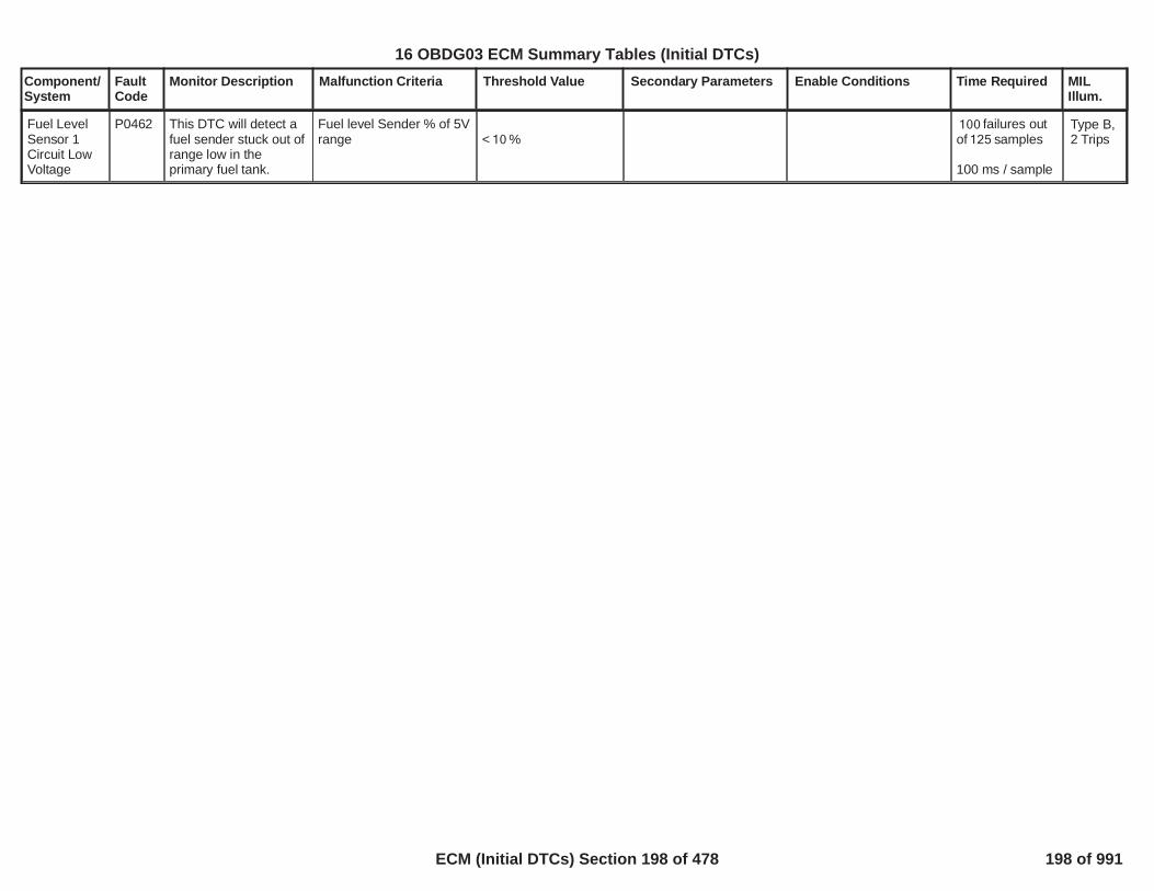
Component/System
FaultCode
Monitor Description Malfunction Criteria Threshold Value Secondary Parameters Enable Conditions Time Required MILIllum.
Fuel LevelSensor 1Circuit LowVoltage
P0462 This DTC will detect afuel sender stuck out ofrange low in theprimary fuel tank.
Fuel level Sender % of 5Vrange < %10
failures out100of samples125
100 ms / sample
Type B,2 Trips
200
16 OBDG03 ECM Summary Tables (Initial DTCs)
ECM (Initial DTCs) Section 198 of 478 198 of 991

Component/System
FaultCode
Monitor Description Malfunction Criteria Threshold Value Secondary Parameters Enable Conditions Time Required MILIllum.
Fuel LevelSensor 1Circuit HighVoltage
P0463 This DTC will detect afuel sender stuck out ofrange high in theprimary fuel tank.
Fuel level Sender % of 5Vrange > %60
failures out100of samples125
100 ms / sample
Type B,2 Trips
201
16 OBDG03 ECM Summary Tables (Initial DTCs)
ECM (Initial DTCs) Section 199 of 478 199 of 991

Component/System
FaultCode
Monitor Description Malfunction Criteria Threshold Value Secondary Parameters Enable Conditions Time Required MILIllum.
Fuel LevelSensor 1CircuitIntermittent
(No ELCP -ConventionalEVAPDiagnostic)
P0464 This DTC will detectintermittent fuel levelsensor signals thatwould have caused theengine-off naturalvacuum small leak testto abort due to anapparent re-fuelingevent.
If a change in fuel level isdetected, the engine-offnatural vacuum test isaborted due to anapparent refueling event.Subsequent to the abort,a refueling rationality testis executed to confirm thatan actual refueling eventoccurred. If a refuelingevent is confirmed, thenthe test sample isconsidered passing.Otherwise, if a refueilngevent is not confirmed,then the test sample isconsidered failing whichindicates an intermittentsignal problem.
An intermittent fuel levelsignal problem is definedas:
The fuel level changes byand does not remainfor seconds during a30
second refueling600rationality test.
> %10> %10
This test will executewhenever the engine-offnatural vacuum small leaktest (P0442) executes
This test isexecuted duringan engine-offnatural vacuumsmall leak test.The test can onlyexecute up toonce per engine-off period.Thelength of the testis determined bythe refuelingrationality test,which can takeup to 600seconds tocomplete.Thetest will report afailure if out of2
samples are3failures.
100 ms / sample
Type A,1 Trips
202
16 OBDG03 ECM Summary Tables (Initial DTCs)
ECM (Initial DTCs) Section 200 of 478 200 of 991

Component/System
FaultCode
Monitor Description Malfunction Criteria Threshold Value Secondary Parameters Enable Conditions Time Required MILIllum.
Cooling Fan1 RelayControlCircuit Open(ODM) (Notused onEREV)
P0480 Diagnoses the coolingfan 1 relay control lowside driver circuit forcircuit faults
Voltage low during driveroff state (indicates opencircuit)
Open Circuit: 200 K impedance
between signal andcontroller ground
Powertrain Relay Voltage Voltage volts11.00 failures out of50samples63
100 ms / sample
Type B,2 Trips
Note: Incertaincontrollers P0691may alsoset (Fan1 ShorttoGround).
203
16 OBDG03 ECM Summary Tables (Initial DTCs)
ECM (Initial DTCs) Section 201 of 478 201 of 991

Component/System
FaultCode
Monitor Description Malfunction Criteria Threshold Value Secondary Parameters Enable Conditions Time Required MILIllum.
EvaporativeEmission(EVAP)System FlowDuring Non-Purge
(No ELCP -ConventionalEVAPDiagnostic)
P0496 This DTC willdetermine if the purgesolenoid is leaking toengine manifoldvacuum.
This test will run withthe purge valve closedand the vent valveclosed.
Tank Vacuumfor
Test time
> Pa2,491seconds5
refer to
in
P0496 Purge ValveLeak Test EngineVacuum Test Time(Cold Start) as aFunction of FuelLevel TableSupporting Tables.
Fuel LevelSystem Voltage
BAROStartup IAT
Startup ECTEngine Off Time
No active DTCs:
% Percent %10 90volts Voltage 11 32
voltskPa70
°C Temperature °C4 34
°C35seconds28,800.0
MAP_SensorFATPS_FAVehicleSpeedSensor_FAIAT_SensorFAECT_Sensor_FAAmbientAirDefaultEnginePowerLimited
P0443P0449P0452P0453P0454
Once per coldstart
Cold start: maxtime is 1,000seconds
Type B,2 Trips
204
16 OBDG03 ECM Summary Tables (Initial DTCs)
ECM (Initial DTCs) Section 202 of 478 202 of 991

Component/System
FaultCode
Monitor Description Malfunction Criteria Threshold Value Secondary Parameters Enable Conditions Time Required MILIllum.
EvaporativeEmissionSystem VentSolenoidControlCircuit Low
(No ELCP -ConventionalEVAPDiagnostic)
P0498 Diagnoses the ventsolenoid low side drivercircuit for circuit faults.
Voltage low during driveroff state (indicates shortto ground)
Short to ground: 0.5 impedence
between signal andcontroller ground
failures out of20samples25
250 ms / sample
Type B,2 Trips
Note: Incertaincontrollers P0449may alsoset (VentSolenoidOpenCircuit)
205
16 OBDG03 ECM Summary Tables (Initial DTCs)
ECM (Initial DTCs) Section 203 of 478 203 of 991

Component/System
FaultCode
Monitor Description Malfunction Criteria Threshold Value Secondary Parameters Enable Conditions Time Required MILIllum.
EvaporativeEmissionSystem VentSolenoidControlCircuit High
(No ELCP -ConventionalEVAPDiagnostic)
P0499 Diagnoses the ventsolenoid low side drivercircuit for circuit faults.If the P0499 is active,an intrusive test isperformed with the ventsolenoid commandedclosed for seconds.15
Voltage low during driveron state (indicates shortto power)
Short to power: 0.5 impedence
between signal andcontroller power
failures out of20samples25
250 ms / sample
Type B,2 Trips
206
16 OBDG03 ECM Summary Tables (Initial DTCs)
ECM (Initial DTCs) Section 204 of 478 204 of 991

Component/System
FaultCode
Monitor Description Malfunction Criteria Threshold Value Secondary Parameters Enable Conditions Time Required MILIllum.
Low EngineSpeed IdleSystem
P0506 This DTC willdetermine if a low idleexists
Filtered Engine SpeedError
filter coefficient
> rpm95.00
0.00375
Baro
Coolant Temp
Engine run time
Ignition voltage
Time since gear change
Time since a TCC modechange
IAT
Vehicle speed
Commanded RPM delta
Idle time
For manualtransmissions:Clutch Pedal PositionorClutch Pedal Position
> kPa70
>KeSPDD_T_EnblECT_Min ( °C) and <60KfECTI_T_EngCoolHotHiThresh ( °C)125Must verifyKfECTI_T_EngCoolHotLoThresh ( ) is less than120KfECTI_T_EngCoolHotHiThresh ( )125
sec60
volts 32 11
sec3
> sec3
> °C-20
mph1.24
rpm25
> sec10
> pct88.00
< pct16.00
Diagnostic runsin every 12.5 msloop
Diagnosticreports pass orfail in 10seconds once allenableconditions aremet
Type B,2 Trips
207
16 OBDG03 ECM Summary Tables (Initial DTCs)
ECM (Initial DTCs) Section 205 of 478 205 of 991

Component/System
FaultCode
Monitor Description Malfunction Criteria Threshold Value Secondary Parameters Enable Conditions Time Required MILIllum.
No active DTCs
PTO not active
Transfer Case not in 4WDLowState
Off-vehicle device control(service bay control) mustnot be active.
following conditions notTRUE:(VeTESR_e_EngSpdReqIntvType =CeTESR_e_EngSpdMinLimit ANDVeTESR_e_EngSpdReqRespType =CeTESR_e_NoSuggestion)
Clutch is not depressed
TC_BoostPresSnsrFAECT_Sensor_FAEnginePowerLimitedEGRValveCircuit_FAEGRValvePerformance_FAIAT_SensorCircuitFAEvapFlowDuringNonPurge_FAFuelTrimSystemB1_FAFuelTrimSystemB2_FAFuelInjectorCircuit_FAMAF_SensorFAEngineMisfireDetected_FAIgnitionOutputDriver_FA
208
16 OBDG03 ECM Summary Tables (Initial DTCs)
ECM (Initial DTCs) Section 206 of 478 206 of 991

Component/System
FaultCode
Monitor Description Malfunction Criteria Threshold Value Secondary Parameters Enable Conditions Time Required MILIllum.
All of the above metfor Idle time
TPS_FATPS_Performance_FAVehicleSpeedSensor_FAFuelLevelDataFaultLowFuelConditionDiagnosticClutch Sensor FAAmbPresDfltdStatusP2771
> sec10
The diagnostic does notrun during autostop asengine is shutdown duringthat time (occurs in ahybrid or 12v start stopvehicle)
209
16 OBDG03 ECM Summary Tables (Initial DTCs)
ECM (Initial DTCs) Section 207 of 478 207 of 991

Component/System
FaultCode
Monitor Description Malfunction Criteria Threshold Value Secondary Parameters Enable Conditions Time Required MILIllum.
High EngineSpeed IdleSystem
P0507 This DTC willdetermine if a high idleexists
Filtered Engine SpeedError
filter coefficient
< rpm-190.00
0.00375
Baro
Coolant Temp
Engine run time
Ignition voltage
Time since gear change
Time since a TCC modechange
IAT
Vehicle speed
Commanded RPM delta
For manualtransmissions:Clutch Pedal PositionorClutch Pedal Position
> kPa70
>KeSPDD_T_EnblECT_Min ( °C) and <60KfECTI_T_EngCoolHotHiThresh ( °C)125Must verifyKfECTI_T_EngCoolHotLoThresh ( ) is less than120KfECTI_T_EngCoolHotHiThresh ( )125
sec60
volts 32 11
sec3
> sec3
> °C-20
mph1.24
rpm25
> pct88.00
< pct16.00
Diagnostic runsin every 12.5 msloop
Diagnosticreports pass orfail in 10seconds once allenableconditions aremet
Type B,2 Trips
210
16 OBDG03 ECM Summary Tables (Initial DTCs)
ECM (Initial DTCs) Section 208 of 478 208 of 991

Component/System
FaultCode
Monitor Description Malfunction Criteria Threshold Value Secondary Parameters Enable Conditions Time Required MILIllum.
No active DTCs
PTO not active
Transfer Case not in 4WDLowState
Off-vehicle device control(service bay control) mustnot be active.
following conditions notTRUE:(VeTESR_e_EngSpdReqIntvType =CeTESR_e_EngSpdMinLimit ANDVeTESR_e_EngSpdReqRespType =CeTESR_e_NoSuggestion)
Clutch is not depressed
TC_BoostPresSnsrFAECT_Sensor_FAEnginePowerLimitedEGRValveCircuit_FAEGRValvePerformance_FAIAT_SensorCircuitFAEvapFlowDuringNonPurge_FAFuelTrimSystemB1_FAFuelTrimSystemB2_FAFuelInjectorCircuit_FAMAF_SensorFAEngineMisfireDetected_FAIgnitionOutputDriver_FATPS_FATPS_Performance_FAVehicleSpeedSensor_FA
211
16 OBDG03 ECM Summary Tables (Initial DTCs)
ECM (Initial DTCs) Section 209 of 478 209 of 991

Component/System
FaultCode
Monitor Description Malfunction Criteria Threshold Value Secondary Parameters Enable Conditions Time Required MILIllum.
All of the above metfor Idle time
FuelLevelDataFaultLowFuelConditionDiagnosticClutch SensorFAAmbPresDfltdStatusP2771
> sec10
The diagnostic does notrun during autostop asengine is shutdown duringthat time (occurs in ahybrid or 12v start stopvehicle)
212
16 OBDG03 ECM Summary Tables (Initial DTCs)
ECM (Initial DTCs) Section 210 of 478 210 of 991

Component/System
FaultCode
Monitor Description Malfunction Criteria Threshold Value Secondary Parameters Enable Conditions Time Required MILIllum.
Cold StartRough Idle
P050D Monitors thecombustionperformance when thecold start emissionreduction strategy isactive by accumulatingand determining thepercentage of enginecycles that have lessthan completecombustion relative tothe total number ofengine cycles in whichDual Pulse is active.
Deceleration index vs.Engine Speed VsEngine load
Deceleration indexcalculation is tailored tospecific vehicle. Tablesused are 1st tablesencountered that are notmax of range.Undetectable region at agiven speed/load point iswhere all tables are maxof range point. seeAlgorithm DescriptionDocument for additionaldetails.
Incomplete combustionidentified by P0300threshold tables:
(>Idle SCD AND>Idle SCD ddt Tables)OR(>Idle Cyl Mode AND> Idle Cyl Mode ddtTables)
Misfire Algorithm Enabled(Refer to P0300 forEnablementRequirements)
OBD ManufacturerEnable Counter
To enable the diagnostic,the Cold Start EmissionReduction Strategy MustBe Active per thefollowing:
Catalyst TemperatureANDEngine CoolantANDEngine CoolantANDBarometric Pressure
In addition, Dual PulseStrategy Is Enabled andActive Per the following:
Engine Speed
Accel Position
Engine Run Time
For the engine speedsand loads in which DualPulse is active:
= 0
< degC300.00
> degC-12.00
<= degC56.00
>= KPa78.00
>= RPM300.00<= RPM2,600.00
<= Pct1.00
< seconds83
Runs once pertrip when thecold startemissionreductionstrategy is activeand Dual Pulseis enabled andactive.
Frequency:100ms
Test completesafter Dual Pulseis no longeractiveORThe first 500engine cycleshave beenreached
Type B,2 Trips
213
16 OBDG03 ECM Summary Tables (Initial DTCs)
ECM (Initial DTCs) Section 211 of 478 211 of 991

Component/System
FaultCode
Monitor Description Malfunction Criteria Threshold Value Secondary Parameters Enable Conditions Time Required MILIllum.
Dual Pulse Error inducedmisfires percentage
Dual Pulse Error inducedmisfires percentage
Engine Cycles
The Cold Start EmissionReduction strategy mustnot be exiting. Thestrategy will exit per thefollowing:
Catalyst TemperatureANDEngine Run Time
OR
Engine Run Time
OR
Barometric Pressure
>= catalyst damagingmisfire
< 90% of the maximumachieveable catalystdamaging misfire.
>= 50< 501
>= degC800.00
>= seconds22.00
>P050D_P1400_CatalystLightOffExtendedEngineRunTimeExit
This Extended Engine runtime exit table is afunction of percentethanol and CatmonsNormRatioEWMA. Referto "Supporting Tables" fordetails.
< KPa78.00
214
16 OBDG03 ECM Summary Tables (Initial DTCs)
ECM (Initial DTCs) Section 212 of 478 212 of 991

Component/System
FaultCode
Monitor Description Malfunction Criteria Threshold Value Secondary Parameters Enable Conditions Time Required MILIllum.
Dual Pulse Strategy willexit per the following:
Engine SpeedORAccel Position
Engine Run Time
Dual Pulse Strategy willalso exit if the any of the"Additional Dual PulseEnabling Criteria" is notsatisfied:
"Additional Dual PulseEnabling Criteria":
Green Engine Enrichment
Misfire ConverterProtection strategy
Engine Metal Overtempstrategy
Fuel control state
Output State Control
DOD Or DFCO
Power Enrichment
Dynamic PowerEnrichment
Piston Protection
Hot Coolant Enrichment
> RPM2,800.00
> Pct30.00
>= seconds83
Not Enabled
Not being requested
Not being requested
Open Loop
Not being requested forfuel
Not Active
Not Active
Not Active
Not Active
Not Active
215
16 OBDG03 ECM Summary Tables (Initial DTCs)
ECM (Initial DTCs) Section 213 of 478 213 of 991

Component/System
FaultCode
Monitor Description Malfunction Criteria Threshold Value Secondary Parameters Enable Conditions Time Required MILIllum.
Injector Flow Test
General Enable
DTC's Not Set:
Not Active
AcceleratorPedalFailureECT_Sensor_FAIAT_SensorCircuitFAMnfdTempSensorCktFACrankSensor_FAFuelInjectorCircuit_FAMAF_SensorFAMAP_SensorFAAnyCamPhaser_TFTKOClutchPstnSnsr FAIAC_SystemRPM_FAIgnitionOutputDriver_FATPS_FAVehicleSpeedSensor_FAFuelInjectorCircuit_TFTKOFHPR_b_FRP_SnsrCkt_FAFHPR_b_FRP_SnsrCkt_TFTKOFHPR_b_PumpCkt_FAFHPR_b_PumpCkt_TFTKOTransmissionEngagedState_FAEngineTorqueEstInaccurateFuelPumpRlyCktFA
216
16 OBDG03 ECM Summary Tables (Initial DTCs)
ECM (Initial DTCs) Section 214 of 478 214 of 991

Component/System
FaultCode
Monitor Description Malfunction Criteria Threshold Value Secondary Parameters Enable Conditions Time Required MILIllum.
Brake AssistVacuum TooLow
P050F Monitors for a brakebooster vacuum leak Brake booster vacuum
drift ratio (EWMA)reaches the fail threshold(based on engine runningcondition) before thesample count threshold isreached, a failure isreported.
Engine Running FailThreshold based on priordiagnostic state(description below)
Diagnostic failed priorloop
Diagnostic passed priorloop
Before the sample counts
Engine Stopped FailThreshold based on priordiagnostic state(description below)
Diagnostic failed priorloop
Diagnostic passed priorloop
Before the sample counts
>= 0.60
>= 0.65
> counts0.00
>= 0.80
>= 0.90
> counts0.00
Diagnostic is enabledand the followingconditions are met forengine run conditions:
No brake booster vacuumsensor faults active
No brake pedal positionsensor faults active
Brake pedal travel is
No mass air flow faults
No manifold air pressurefaults
Mass air flow estimate
Manifold air pressure
Engine vacuum stabilitytime has reached
Difference between brakebooster vacuum andmanifold air pressure is
OR
Diagnostic is enabledfor the following engineauto off conditions:
No brake booster vacuumsensor faults active
Enabled
< percent -8.00 5.00percent offset
>= grams / second6.00
<= kPa20.00
>= seconds0.70
> kPa10.00
Enabled
Performed every100 msecond
Minimum time topass:
Engine Runningsecond0.00
Engine Stoppedsecond0.00
Type B,2 Trips
217
16 OBDG03 ECM Summary Tables (Initial DTCs)
ECM (Initial DTCs) Section 215 of 478 215 of 991
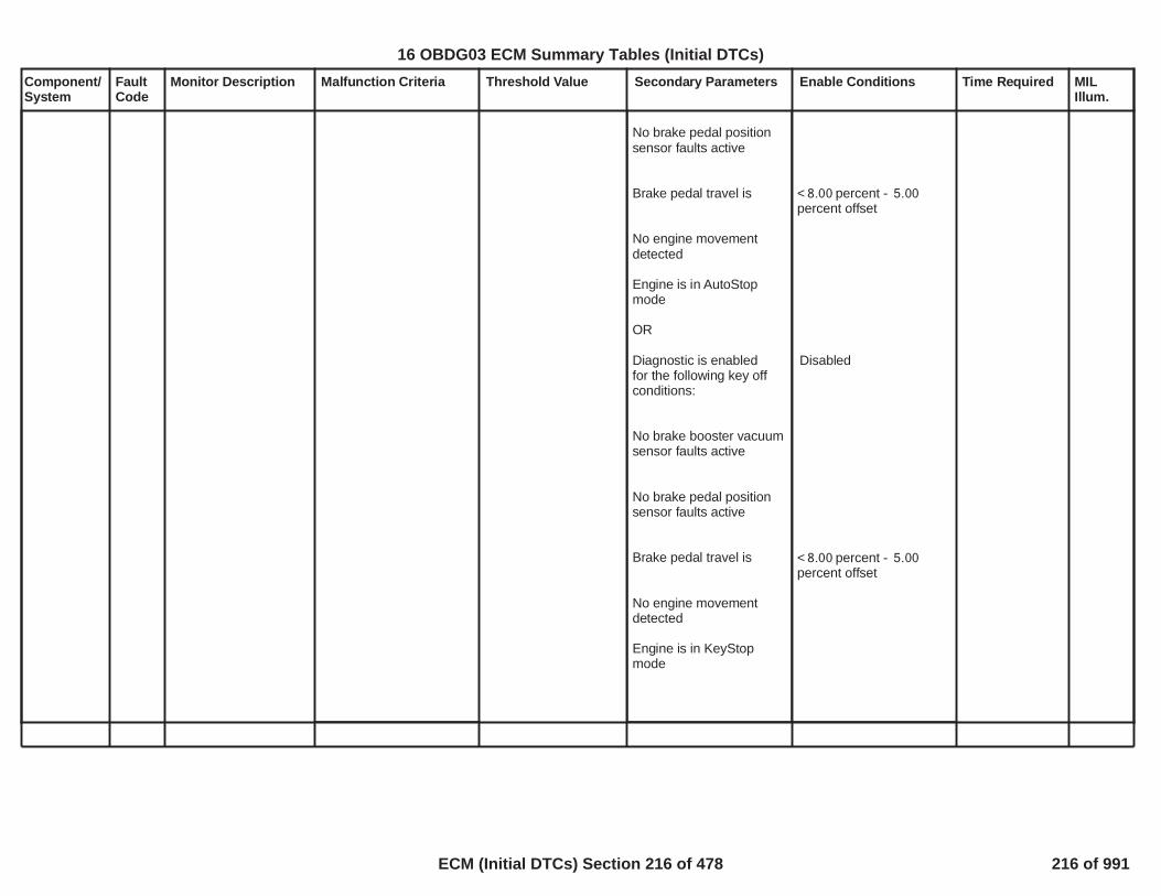
Component/System
FaultCode
Monitor Description Malfunction Criteria Threshold Value Secondary Parameters Enable Conditions Time Required MILIllum.
No brake pedal positionsensor faults active
Brake pedal travel is
No engine movementdetected
Engine is in AutoStopmode
OR
Diagnostic is enabledfor the following key offconditions:
No brake booster vacuumsensor faults active
No brake pedal positionsensor faults active
Brake pedal travel is
No engine movementdetected
Engine is in KeyStopmode
< percent -8.00 5.00percent offset
Disabled
< percent -8.00 5.00percent offset
218
16 OBDG03 ECM Summary Tables (Initial DTCs)
ECM (Initial DTCs) Section 216 of 478 216 of 991

Component/System
FaultCode
Monitor Description Malfunction Criteria Threshold Value Secondary Parameters Enable Conditions Time Required MILIllum.
Two Stage Oil PumpEOP Sensor Test withEngine Running
If enabled:
To Fail when previouslypassing with the enginerunning:
Filtered Engine OilPressure below expectedthreshold
OR
Filtered Engine OilPressure above expectedthreshold
To pass when previouslyfailing:
Filtered Engine OilPressure above lowthreshold plus an offset
OR
Filtered Oil Pressure<P0521_LowMinOilPresFail - Two Stage OilPump
OR
Filtered Oil Pressure>(P0521_P06DD_P06DE_OP_HiStatePressure* + kPa)1.10 114.0
Filtered Oil Pressure> (
kPa+10.0P0521_LowMinOilPresFail - Two Stage OilPump)
OR
Two Stage Oil Pump isPresent = TRUE
Engine RunningDiagnostic Status
Engine Off RationalityTest Diagnostic ReportingStatus
Oil Pressure Sensor InUse
Engine Running
Ambient Air Pressure
Oil Aeration(= TRUE if engine speed> RPM for longer5,000than seconds)30.0
Filtered Engine Speedwithin range
Modelled Oil Temperaturewithin range
No active DTC's
TRUE
Enabled
Test not report a fail state
Yes
seconds20.0
kPa70.0
FALSE
RPM Filtered1,500Engine Speed 4,500RPM
deg C Oil Temp 40.0deg C120.0
Fault bundles:MAF_SensorFAECT_Sensor_FAIAT_SensorFAEngOilPressureSensorCktFAAmbientAirDefaultEngOilTempFACrankSensor_FA
errors40out of 50samples.
Performed every100 msec
passes10out of 50samples.
Performed every100 msec
Engine OilPressure(EOP)SensorPerformance- Two StageOil Pump
P0521 Determines if theEngine Oil Pressure(EOP) Sensor is stuckor biased in range
Type B,2 Trips
219
16 OBDG03 ECM Summary Tables (Initial DTCs)
ECM (Initial DTCs) Section 217 of 478 217 of 991

Component/System
FaultCode
Monitor Description Malfunction Criteria Threshold Value Secondary Parameters Enable Conditions Time Required MILIllum.
Filtered Engine OilPressure below highthreshold minus an offset
Filtered Oil Pressure< (P0521_P06DD_P06DE_OP_HiStatePressure* + kPa) -1.10 114.0
kPa10.0
(Details on SupportingTables Tab:P0521_LowMinOilPresFail - Two Stage OilPumpP0521_P06DD_P06DE_OP_HiStatePressure)
Two Stage Oil PumpEOP Sensor Test withEngine Off
If enabled:
To Fail when previouslypassing with the engineoff:
Filtered Engine OilPressure greater thanthreshold
Filtered Oil PressurekPa40.0
Two Stage Oil Pump isPresent = TRUE
Engine Off RationalityTest Diagnostic Status
Engine RunningRationality TestDiagnostic Status
Modelled Oil TemperatureNo Engine MovementNo active DTC's
TRUE
Enabled
Test not report a fail state
deg C70.0> seconds4.0EngineModeNotRunTimer_FAEngOilTempFAEngOilPressureSensorCktFACrankSensor_FA
errors20out of 40samples.
Run once per trip
220
16 OBDG03 ECM Summary Tables (Initial DTCs)
ECM (Initial DTCs) Section 218 of 478 218 of 991

Component/System
FaultCode
Monitor Description Malfunction Criteria Threshold Value Secondary Parameters Enable Conditions Time Required MILIllum.
Engine OilPressure(EOP)SensorCircuit LowVoltage
P0522 Determines if theEngine Oil Pressure(EOP) Sensor circuitvoltage is too low
(Engine Oil PressureSensor Circuit Voltage) ÷5 Volts) *100 < percent5.00
Engine Speed EnableEngine Speed Disable
Oil Pressure Sensor InUse
Diagnostic Status
> rpm400< rpm350
Yes
Enabled
failures out800of 1,000samples
Performed every6.25 msec
Type B,2 Trips
221
16 OBDG03 ECM Summary Tables (Initial DTCs)
ECM (Initial DTCs) Section 219 of 478 219 of 991

Component/System
FaultCode
Monitor Description Malfunction Criteria Threshold Value Secondary Parameters Enable Conditions Time Required MILIllum.
Engine OilPressure(EOP)SensorCircuit HighVoltage
P0523 Determines if theEngine Oil Pressure(EOP) Sensor circuitvoltage is too high
(Engine Oil PressureSensor Circuit Voltage) ÷5 Volts) *100
> percent95.00Oil Pressure Sensor InUse
Diagnostic Status
Yes
Enabled
failures out800of 1,000samplesPerformed every6.25 msec
Type B,2 Trips
222
16 OBDG03 ECM Summary Tables (Initial DTCs)
ECM (Initial DTCs) Section 220 of 478 220 of 991

Component/System
FaultCode
Monitor Description Malfunction Criteria Threshold Value Secondary Parameters Enable Conditions Time Required MILIllum.
BrakeBoosterPressureSensorPerformance
P0556 Determines if the BrakeBooster VacuumSensor is stuck orskewed within thenormal operating rangeby comparing theengine vacuum to thebrake booster vacuumwhen the engine isproducing a largeamount of vacuum
Engine vs brake boostervacuum sensor values arecompared when % throttle< value for a time period.When throttle once again> calibrated value, minand max vacuum sensorvalues are normalizedand subtracted from a 1storder lag filter value of 1.A properly operatingvacuum sensor wouldhave a normalized resultof 1 or greater. If thenormalized result isgreater than 1 it isconsidered 1. The 1storder lag filter value wouldbe 0 in a passing system.
1st order lag fail threshold
1st order lag re-passthreshold
> 0.20
< 0.4
Throttle Area (with idleincluded) for time periodof
BrkBoostVacDiff
For time period ofANDVacuum Delta
Diagnostic enabled/disabled
No active DTC's
<= Percent for >5.0 3.0seconds
> kPa0.3
>= Seconds0.2
>= kPa6.0
1.00
Fault bundles:MAP_SensorFATPS_FABrakeBoosterSensorCktFA
Pass counterincrementedwhen enableconditions aremet, passachieved whencounter >= 7
Performed every100 msec
Type B,2 Trips
223
16 OBDG03 ECM Summary Tables (Initial DTCs)
ECM (Initial DTCs) Section 221 of 478 221 of 991

Component/System
FaultCode
Monitor Description Malfunction Criteria Threshold Value Secondary Parameters Enable Conditions Time Required MILIllum.
BrakeBoosterPressureSensorCircuit LowVoltage
P0557 Determines if the BrakeBooster PressureSensor circuit voltageis too low
(Brake Booster PressureSensor Voltage) ÷ 5 Volts*100
< percent5.00 Brake booster diagnosticenabled/disabled
Brake booster pressuresensor present
Enabled
Present
failures out320of samples400
Performed every12.5 msec
Type B,2 Trips
224
16 OBDG03 ECM Summary Tables (Initial DTCs)
ECM (Initial DTCs) Section 222 of 478 222 of 991

Component/System
FaultCode
Monitor Description Malfunction Criteria Threshold Value Secondary Parameters Enable Conditions Time Required MILIllum.
BrakeBoosterPressureSensorCircuit HighVoltage
P0558 Determines if the BrakeBooster PressureSensor circuit voltageis too high
(Brake Booster PressureSensor Voltage) ÷ 5 Volts*100
> percent95.00 Brake booster diagnosticenabled/disabled
Brake booster pressuresensor present
Enabled
Present
failures2,000out of 2,400samples
Performed every12.5 msec
Type B,2 Trips
225
16 OBDG03 ECM Summary Tables (Initial DTCs)
ECM (Initial DTCs) Section 223 of 478 223 of 991
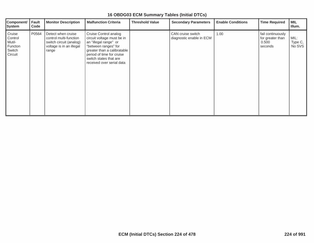
Component/System
FaultCode
Monitor Description Malfunction Criteria Threshold Value Secondary Parameters Enable Conditions Time Required MILIllum.
CruiseControlMutil-FunctonSwitchCircuit
P0564 Detect when cruisecontrol multi-functionswitch circuit (analog)voltage is in an illegalrange
Cruise Control analogcircuit voltage must be inan "illegal range" or"between ranges" forgreater than a calibratableperiod of time for cruiseswitch states that arereceived over serial data
CAN cruise switchdiagnostic enable in ECM
1.00 fail continuouslyfor greater than0.500seconds
MIL:Type C,No SVS
226
16 OBDG03 ECM Summary Tables (Initial DTCs)
ECM (Initial DTCs) Section 224 of 478 224 of 991

Component/System
FaultCode
Monitor Description Malfunction Criteria Threshold Value Secondary Parameters Enable Conditions Time Required MILIllum.
CruiseControl OnSwitchCircuit
P0565 Cruise Control On switchremains applied forgreater than a calibratableperiod of time forarchitecture where cruiseswitch states are receivedover serial data
CAN cruise switchdiagnostic enable in ECM
1.00 fail continuouslyfor greater than
seconds20.00
MILType C,No SVS
227
16 OBDG03 ECM Summary Tables (Initial DTCs)
ECM (Initial DTCs) Section 225 of 478 225 of 991

Component/System
FaultCode
Monitor Description Malfunction Criteria Threshold Value Secondary Parameters Enable Conditions Time Required MILIllum.
CruiseControlResumeCircuit
P0567 Detects a failure of thecruise resume switch ina continously appliedstate
Cruise Control Resumeswitch remains applied forgreater than a calibratableperiod of time forarchitecture where cruiseswitch states are receivedover serial data
CAN cruise switchdiagnostic enable in ECM
1.00 fail continuouslyfor greater than89.000seconds
MIL:Type C,No SVS
228
16 OBDG03 ECM Summary Tables (Initial DTCs)
ECM (Initial DTCs) Section 226 of 478 226 of 991

Component/System
FaultCode
Monitor Description Malfunction Criteria Threshold Value Secondary Parameters Enable Conditions Time Required MILIllum.
CruiseControl SetCircuit
P0568 Detects a failure of thecruise set switch in acontinously appliedstate
Cruise Control Set switchremains applied forgreater than a calibratableperiod of time forarchitecture where cruiseswitch states are receivedover serial data
CAN cruise switchdiagnostic enable in ECM
1.00 fail continuouslyfor greater than89.000seconds
MIL:Type C,No SVS
229
16 OBDG03 ECM Summary Tables (Initial DTCs)
ECM (Initial DTCs) Section 227 of 478 227 of 991

Component/System
FaultCode
Monitor Description Malfunction Criteria Threshold Value Secondary Parameters Enable Conditions Time Required MILIllum.
CruiseControlCancelSwitchCircuit
P056C Cruise Control Cancelswitch remains applied forgreater than a calibratableperiod of time forarchitecture where cruiseswitch states are receivedover serial data
CAN cruise switchdiagnostic enable in ECM
1.00 fail continuouslyfor greater than
seconds20.00
MIL:Type C,No SVS
230
16 OBDG03 ECM Summary Tables (Initial DTCs)
ECM (Initial DTCs) Section 228 of 478 228 of 991

Component/System
FaultCode
Monitor Description Malfunction Criteria Threshold Value Secondary Parameters Enable Conditions Time Required MILIllum.
CruiseControl InputCircuit
P0575 Detects rolling count orprotection value errorsin Cruise ControlSwitch Status serialdata signal
If x of y rolling count /protection value faultsoccur, disable cruise forduration of fault
Cruise Control SwitchSerial Data ErrorDiagnostic Enable
1.00 10/16counts
MIL:Type C,No SVS
231
16 OBDG03 ECM Summary Tables (Initial DTCs)
ECM (Initial DTCs) Section 229 of 478 229 of 991

Component/System
FaultCode
Monitor Description Malfunction Criteria Threshold Value Secondary Parameters Enable Conditions Time Required MILIllum.
. Brake Pedal PositionSensor Circuit Range /Performance DiagnosticEnable
1.00
ignition voltage > 10.00
Brake PedalPositionSensorCircuitRange/Performance
P057B This diagnosticmonitors the BrakePedal Position Sensorfor a stuck in rangefailure
MIL:Type A,1 Trips
Calculated EWMA valuemust be greater thancalibratable theshold aftercalibratable number oftests have completed toreport a "test passed" forP057B
EWMA value looked upin supporting tableP057BKtBRKI_K_FastTestPointWeight as a functionof calculated brakepedal position deltaEWMA value is > 0.80
calculated brake pedalposition delta samplecounter >
for fast test50.00
OR
calculated brake pedalposition delta samplecounter > for1,000.00slow test
calculated brake pedalposition delta > 8.00
OR (for slow test)
shift lever has been inpark once this key cycle
vehicle speed >= 5.00
accelerator pedal position< 5.00
total number ofEWMA tests >20.00
Calculated EWMA Valuemust be less thancalibratable thresholdafter calibratable numberof tests have completed toreport a "test failed" forP057B. This test runsonce per key cycle
EWMA value looked upin supporting tableP057BKtBRKI_K_CmpltTestPointWeightas a function ofcalculated brake pedalposition deltaEWMA value is lessthatn 0.40
no DTC's active (P057C,P057D)
shift lever has been inpark once this key cycle
vehicle speed >= 5.00
accelerator pedal position< 5.00
total number ofEWMA tests >2.00
232
16 OBDG03 ECM Summary Tables (Initial DTCs)
ECM (Initial DTCs) Section 230 of 478 230 of 991

Component/System
FaultCode
Monitor Description Malfunction Criteria Threshold Value Secondary Parameters Enable Conditions Time Required MILIllum.
Brake PedalPositionSensorCircuit Low
P057C detects short to groundfor brake pedal positionsensor
If x of y samples areobserved below failurethreshold, default brakepedal position to zeropercent.
5.00 Brake Pedal PositionSensore Low VoltageDiagnostic Enable
1.0020/ 32.00counts
MIL:Type A,1 Trips
233
16 OBDG03 ECM Summary Tables (Initial DTCs)
ECM (Initial DTCs) Section 231 of 478 231 of 991

Component/System
FaultCode
Monitor Description Malfunction Criteria Threshold Value Secondary Parameters Enable Conditions Time Required MILIllum.
Brake PedalPositionSensorCircuit High
P057D detects open circuit forbrake pedal positionsensor
If x of y samples areobserved above failurethreshold, default brakepedal position to zeropercent and set DTC
95.00 Brake Pedal PositionSensore High VoltageDiagnostic Enable
1.00 /20.00
counts32.00
MIL:Type A,1 Trips
234
16 OBDG03 ECM Summary Tables (Initial DTCs)
ECM (Initial DTCs) Section 232 of 478 232 of 991

Component/System
FaultCode
Monitor Description Malfunction Criteria Threshold Value Secondary Parameters Enable Conditions Time Required MILIllum.
CruiseControlMulti-functionCircuit LowVoltage
P0580 detects short to groundfailure for cruise multi-function switch circuit
Cruise Control analogcircuit voltage must be inan "Open Short ToGround" for greater than acalibratable period of timefor cruise switch statesthat are received overserial data
CAN cruise switchdiagnostic enable in ECM
1.00 fail continuouslyfor greater than2.00seconds
MIL:Type C,No SVS
235
16 OBDG03 ECM Summary Tables (Initial DTCs)
ECM (Initial DTCs) Section 233 of 478 233 of 991

Component/System
FaultCode
Monitor Description Malfunction Criteria Threshold Value Secondary Parameters Enable Conditions Time Required MILIllum.
CruiseControlMulti-functionCircuit HighVoltage
P0581 Cruise Control analogcircuit voltage must be inan "Short To Power" forgreater than a calibratableperiod of time for cruiseswitch states that arereceived over serial data
CAN cruise switchdiagnostic enable in ECM
1.00 fail continuouslyfor greater than2.00seconds
MIL:Type C,No SVS
236
16 OBDG03 ECM Summary Tables (Initial DTCs)
ECM (Initial DTCs) Section 234 of 478 234 of 991

Component/System
FaultCode
Monitor Description Malfunction Criteria Threshold Value Secondary Parameters Enable Conditions Time Required MILIllum.
BatteryMonitorModulePerformance
P058A This DTC monitors fora battery moduleinternal fault
Battery Module signals aninternal fault via LIN bus
VeVITR_e_IBS_InternalFault
=CeVITR_e_DiagFailed
The diagnostic is enabled
System DiagnosticsDisabled
Power Mode
12V System ReferenceVoltage
LIN Bus Off or BatteryModule CommunicationFaults Active
Outside Air Temperature
Outside Air TemperatureValidity Bit
= (1 indicates enabled)1
= False
Not equal off
> Volts9.00and< Volts99.00
= False
> Celsius-20.00and< Celsius50.00
=True
Diagnostic runsin the 250 msloop
Type B,2 Trips
237
16 OBDG03 ECM Summary Tables (Initial DTCs)
ECM (Initial DTCs) Section 235 of 478 235 of 991

Component/System
FaultCode
Monitor Description Malfunction Criteria Threshold Value Secondary Parameters Enable Conditions Time Required MILIllum.
BatteryMonitorModuleCurrentMonitoringPerformance
P058B This DTC monitors fora battery modulecurrent fault
Battery Module signals aninternal fault via LIN bus
VeVITR_e_BatCurrRatDiag
=CeVITR_e_DiagFailed
The diagnostic is enabled
System DiagnosticsDisabled
Power Mode
12V System ReferenceVoltage
LIN Bus Off or BatteryModule CommunicationFaults Active
Outside Air Temperature
Outside Air TemperatureValidity Bit
= (1 indicates enabled)1
= False
Not equal off
> Volts9.00and< Volts99.00
= False
> Celsius-20.00and< Celsius50.00
= True
Diagnostic runsin the 250 msloop
Type B,2 Trips
238
16 OBDG03 ECM Summary Tables (Initial DTCs)
ECM (Initial DTCs) Section 236 of 478 236 of 991
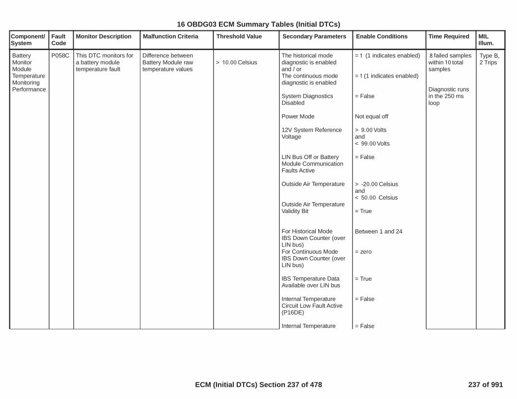
Component/System
FaultCode
Monitor Description Malfunction Criteria Threshold Value Secondary Parameters Enable Conditions Time Required MILIllum.
BatteryMonitorModuleTemperatureMonitoringPerformance
P058C This DTC monitors fora battery moduletemperature fault
Difference betweenBattery Module rawtemperature values
> Celsius10.00The historical modediagnostic is enabledand / orThe continuous modediagnostic is enabled
System DiagnosticsDisabled
Power Mode
12V System ReferenceVoltage
LIN Bus Off or BatteryModule CommunicationFaults Active
Outside Air Temperature
Outside Air TemperatureValidity Bit
For Historical ModeIBS Down Counter (overLIN bus)For Continuous ModeIBS Down Counter (overLIN bus)
IBS Temperature DataAvailable over LIN bus
Internal TemperatureCircuit Low Fault Active(P16DE)
Internal Temperature
= (1 indicates enabled)1
= (1 indicates enabled)1
= False
Not equal off
> Volts9.00and< Volts99.00
= False
> Celsius-20.00and< Celsius50.00
= True
Between 1 and 24
= zero
= True
= False
= False
failed samples8within total10samples
Diagnostic runsin the 250 msloop
Type B,2 Trips
239
16 OBDG03 ECM Summary Tables (Initial DTCs)
ECM (Initial DTCs) Section 237 of 478 237 of 991

Component/System
FaultCode
Monitor Description Malfunction Criteria Threshold Value Secondary Parameters Enable Conditions Time Required MILIllum.
Circuit High Fault Active(P16DF)
Battery ModuleTemperature Too HighFault Active (P058E)
Battery ModuleTemperature Too LowFault Active (P058F)
= False
= False
240
16 OBDG03 ECM Summary Tables (Initial DTCs)
ECM (Initial DTCs) Section 238 of 478 238 of 991

Component/System
FaultCode
Monitor Description Malfunction Criteria Threshold Value Secondary Parameters Enable Conditions Time Required MILIllum.
BatteryMonitorModuleVoltageMonitoringPerformance
P058D This DTC monitors fora battery modulevoltage fault
Difference between12V System ReferenceVoltageandIBS 12V Battery Voltagevalues
> Volts5.00 The diagnostic is enabled
System DiagnosticsDisabled
Power Mode
12V System ReferenceVoltage
LIN Bus Off or BatteryModule CommunicationFaults Active
Outside Air Temperature
Outside Air TemperatureValidity Bit
IBS Voltage and CurrentData Available over LINbus
Battery Monitor ModuleCircuit Low Voltage FaultActive (P16D4)
Battery Monitor ModuleCircuit High Voltage FaultActive (P16D5)
= (1 indicates enabled)1
= False
Not equal off
> Volts9.00and< Volts99.00
= False
> Celsius-20.00and< Celsius50.00
= True
= True
= False
= False
failed32sampleswithin total40samples
Diagnostic runsin the 250 msloop
Type B,2 Trips
241
16 OBDG03 ECM Summary Tables (Initial DTCs)
ECM (Initial DTCs) Section 239 of 478 239 of 991

Component/System
FaultCode
Monitor Description Malfunction Criteria Threshold Value Secondary Parameters Enable Conditions Time Required MILIllum.
BatteryMonitorModuleTemperatureToo High
P058E This DTC monitors fora battery moduletemperature too highfault
Battery Module rawtemperature 2 value > Celsius120.00
The historical modediagnostic is enabledand / orThe continuous modediagnostic is enabled
System DiagnosticsDisabled
Power Mode
12V System ReferenceVoltage
LIN Bus Off or BatteryModule CommunicationFaults Active
Outside Air Temperature
Outside Air TemperatureValidity Bit
For Historical ModeIBS Down Counter (overLIN bus)For Continuous ModeIBS Down Counter (overLIN bus)
IBS Measure TemperatureData Available over LINbus
= (1 indicates enabled)1
= (1 indicates enabled)1
= False
Not equal off
> Volts9.00and< Volts99.00
= False
> Celsius-20.00and< Celsius50.00
= True
Between 1 and 24
= zero
= True
failed samples4within total5samples
Diagnostic runsin the 250 msloop
Type B,2 Trips
242
16 OBDG03 ECM Summary Tables (Initial DTCs)
ECM (Initial DTCs) Section 240 of 478 240 of 991

Component/System
FaultCode
Monitor Description Malfunction Criteria Threshold Value Secondary Parameters Enable Conditions Time Required MILIllum.
BatteryMonitorModuleTemperatureToo Low
P058F This DTC monitors fora battery moduletemperature too lowfault
Battery Module rawtemperature 2 value < Celsius-43.00
The historical modediagnostic is enabledand / orThe continuous modediagnostic is enabled
System DiagnosticsDisabled
Power Mode
12V System ReferenceVoltage
LIN Bus Off or BatteryModule CommunicationFaults Active
Outside Air Temperature
Outside Air TemperatureValidity Bit
For Historical ModeIBS Down Counter (overLIN bus)For Continuous ModeIBS Down Counter (overLIN bus)
IBS Measure TemperatureData Available over LINbus
= (1 indicates enabled)1
= (1 indicates enabled)1
= False
Not equal off
> Volts9.00and< Volts99.00
= False
> Celsius-20.00and< Celsius50.00
= True
Between 1 and 24
= zero
= True
failed samples4within total5samples
Diagnostic runsin the 250 msloop
Type B,2 Trips
243
16 OBDG03 ECM Summary Tables (Initial DTCs)
ECM (Initial DTCs) Section 241 of 478 241 of 991

Component/System
FaultCode
Monitor Description Malfunction Criteria Threshold Value Secondary Parameters Enable Conditions Time Required MILIllum.
Active GrillAir Shutter APerformance/Stuck OFF
P059F Compare commandedshutter A position tosensed position
Consecutive failedintrusive positionperformance test count
>= 5.00 1. Ignition Run_CrackActive,2. Ignition Run_Crank
ANDIgnition AccessoryANDECU Awake,
3. Command Shutter1Enable
1. = TRUE,
2. = FALSEAND= FALSEAND= TRUE,
3. = TRUE
1 sample / 100millisec
Type B,2 Trips
244
16 OBDG03 ECM Summary Tables (Initial DTCs)
ECM (Initial DTCs) Section 242 of 478 242 of 991

Component/System
FaultCode
Monitor Description Malfunction Criteria Threshold Value Secondary Parameters Enable Conditions Time Required MILIllum.
ColdStrtA_CamPstnB1
P05CC Detects a VVT systemerror during Cold Startsby comparing thedesired and actual campositions when VVT isactivated
Camshaft position error[absolute value of(desired position - actualposition)] is compared tothresholds to determine ifexcessive
(Intake cam Bank 1)
Cam Position Error >deg.6.00
Intake Cam Phsr Enable
System Voltage
Engine Running
Power Take Off (PTO)active
Catalyst WarmupEnabled
Desired cam position
Desired AND Measuredcam position
Desired cam positionvariation
No Active DTCs
= TRUE
> Volts11.00
= TRUE
= FALSE
= TRUE
> 0 deg
> deg6.00AND< deg26.00
< deg for3.00(P0011_P05CC_StablePositionTimeIc1) seconds
P0010P2088P2089
65failures out of75samples
100 ms /sample
Type B,2 Trips
245
16 OBDG03 ECM Summary Tables (Initial DTCs)
ECM (Initial DTCs) Section 243 of 478 243 of 991

Component/System
FaultCode
Monitor Description Malfunction Criteria Threshold Value Secondary Parameters Enable Conditions Time Required MILIllum.
ColdStrtB_CamPstnB1
P05CE Detects a VVT systemerror during Cold Startsby comparing thedesired and actual campositions when VVT isactivated
Camshaft position error[absolute value of(desired position - actualposition)] is compared tothresholds to determine ifexcessive
(Exhaust cam Bank 1)
Cam Position Error >deg.6.00
Exhaust Cam PhsrEnable
System Voltage
Engine Running
Power Take Off (PTO)active
Catalyst WarmupEnabled
Desired cam position
Desired AND Measuredcam position
Desired cam positionvariation
No Active DTCs
= TRUE
> volts11.00
= TRUE
= FALSE
= TRUE
> 0 deg
> deg6.00AND< deg32.00
< deg for3.00(P0014_P05CE_StablePositionTimeEc1) sec
P0013P2090P2091
65failures out of75samples
100 ms /sample
Type B,2 Trips
246
16 OBDG03 ECM Summary Tables (Initial DTCs)
ECM (Initial DTCs) Section 244 of 478 244 of 991
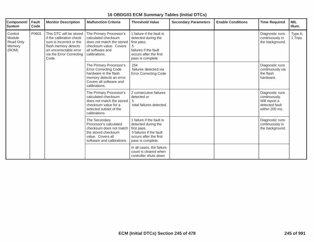
Component/System
FaultCode
Monitor Description Malfunction Criteria Threshold Value Secondary Parameters Enable Conditions Time Required MILIllum.
The Primary Processor'scalculated checksumdoes not match the storedchecksum value. Coversall software andcalibrations.
1 failure if the fault isdetected during thefirst pass.5failures if the faultoccurs after the firstpass is complete.
Diagnostic runscontinuously inthe background.
ControlModuleRead OnlyMemory(ROM)
P0601 This DTC will be storedif the calibration checksum is incorrect or theflash memory detectsan uncorrectable errorvia the Error CorrectingCode.
Type A,1 Trips
The Primary Processor'sError Correcting Codehardware in the flashmemory detects an error.Covers all software andcalibrations.
254failures detected viaError Correcting Code
Diagnostic runscontinuously viathe flashhardware.
The Primary Processor'scalculated checksumdoes not match the storedchecksum value for aselected subset of thecalibrations.
2 consecutive failuresdetected or5total failures detected.
Diagnostic runscontinuously.Will report adetected faultwithin 200 ms.
The SecondaryProcessor's calculatedchecksum does not matchthe stored checksumvalue. Covers allsoftware and calibrations.
1 failure if the fault isdetected during thefirst pass.
failures if the fault5occurs after the firstpass is complete.
Diagnostic runscontinuously inthe background.
In all cases, the failurecount is cleared whencontroller shuts down
247
16 OBDG03 ECM Summary Tables (Initial DTCs)
ECM (Initial DTCs) Section 245 of 478 245 of 991

Component/System
FaultCode
Monitor Description Malfunction Criteria Threshold Value Secondary Parameters Enable Conditions Time Required MILIllum.
ControlModule NotProgrammed
P0602 This DTC will be storedif the ECU is a servicepart that has not beenprogrammed.
Service (reflash) controllercalibration present
= 1 none Diagnostic runsat powerup andonce per secondcontinuouslyafter that
Type A,1 Trips
248
16 OBDG03 ECM Summary Tables (Initial DTCs)
ECM (Initial DTCs) Section 246 of 478 246 of 991
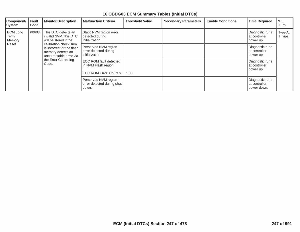
Component/System
FaultCode
Monitor Description Malfunction Criteria Threshold Value Secondary Parameters Enable Conditions Time Required MILIllum.
Static NVM region errordetected duringinitialization
Diagnostic runsat controllerpower up.
ECM LongTermMemoryReset
P0603 This DTC detects aninvalid NVM.This DTCwill be stored if thecalibration check sumis incorrect or the flashmemory detects anuncorrectable error viathe Error CorrectingCode.
Type A,1 Trips
Perserved NVM regionerror detected duringinitialization
Diagnostic runsat controllerpower up.
ECC ROM fault detectedin NVM Flash region
ECC ROM Error Count > 1.00
Diagnostic runsat controllerpower up.
Perserved NVM regionerror detected during shutdown.
Diagnostic runsat controllerpower down.
249
16 OBDG03 ECM Summary Tables (Initial DTCs)
ECM (Initial DTCs) Section 247 of 478 247 of 991

Component/System
FaultCode
Monitor Description Malfunction Criteria Threshold Value Secondary Parameters Enable Conditions Time Required MILIllum.
Indicates that the primaryprocessor is unable tocorrectly read data fromor write data to systemRAM. Detects data readdoes not match datawritten >=
counts254 Will finish firstmemory scanwithin 30seconds at allengineconditions -diagnostic runscontinuously(backgroundloop)
ECM RAMFailure
P0604 Indicates that the ECMhas detected a RAMfault
Type A,1 Trips
Indicates that the primaryprocessor is unable tocorrectly read data fromor write data to cachedRAM. Detects data readdoes not match datawritten >=
counts254 Will finish firstmemory scanwithin 30seconds at allengineconditions -diagnostic runscontinuously(backgroundloop)
Indicates that the primaryprocessor is unable tocorrectly read data fromor write data to TPU RAM.Detects data read doesnot match data written >=
counts5 Will finish firstmemory scanwithin 30seconds at allengineconditions -diagnostic runscontinuously(backgroundloop)
Indicates that the primaryprocessor detects amismatch between thedata and dual data isfound during RAMupdates. Detects amismatch in data and dualdata updates >
s0.45384 When dual storeupdates occur.
250
16 OBDG03 ECM Summary Tables (Initial DTCs)
ECM (Initial DTCs) Section 248 of 478 248 of 991

Component/System
FaultCode
Monitor Description Malfunction Criteria Threshold Value Secondary Parameters Enable Conditions Time Required MILIllum.
Indicates that the primaryprocessor detects anillegal write attempt toprotected RAM. Numberof illegal writes are >
counts0 Diagnostic runscontinuously(backgroundloop)
Indicates that thesecondary processor isunable to correctly readdata from or write data tosystem RAM. Detectsdata read does not matchdata written >=
counts5 Will finish firstmemory scanwithin 30seconds at allengineconditions -diagnostic runscontinuously(backgroundloop)
251
16 OBDG03 ECM Summary Tables (Initial DTCs)
ECM (Initial DTCs) Section 249 of 478 249 of 991

Component/System
FaultCode
Monitor Description Malfunction Criteria Threshold Value Secondary Parameters Enable Conditions Time Required MILIllum.
Loss or invalid messageof SPI communicationfrom the SecondaryProcessor at initializationdetected by the PrimaryProcessor or loss orinvalid message of SPIcommunication from theSecondary Processorafter a valid message wasreceived by the PrimaryProcessor
Loss or invalidmessage atinitialization detectedor loss or invalidmessage after a validmessage was recieved
Run/Crank voltage >=6.41or Run/Crank voltage >=
,11.00else the failure will bereported for all conditions
In the primaryprocessor,
/ counts159 399intermittent or
counts39continuous;
counts39continuous @initialization.12.5 ms /count inthe ECM mainprocessor
Internal ECMProcessorIntegrityFault
P0606 Indicates that the ECMhas detected aninternal processorintegrity fault
Type A,1 Trips
Loss or invalid messageof SPI communicationfrom the PrimaryProcessor at initializationdetected by theSecondary Processor orloss or invalid message ofSPI communication fromthe Primary Processorafter a valid message wasreceived by theSecondary Processor
Loss or invalidmessage atinitialization detectedor loss or invalidmessage after a validmessage was recieved
In the secondaryprocessor,
/ counts20 200intermittent or
s0.1875continuous;
s0.4750continuous @initialization.12.5 ms /count inthe ECMsecondaryprocessor
Checks for stack over orunderflow in secondaryprocessor by looking forcorruption of knownpattern at stackboundaries. Checksnumber of stack over/under flow since lastpowerup reset >=
5 KeMEMD_b_StackLimitTestEnbl == 1Value ofKeMEMD_b_StackLimitTestEnbl is: .1(If 0, this test is disabled)
variable,depends onlength of time tocorrupt stack
MAIN processor is verifiedby responding to a seedsent from the secondarywith a key response tosecondary. Checksnumber of incorrect keys
2 incorrect seedswithin 8 messages,0.2000seconds
ignition in Run or Crank 150 ms for oneseed continuallyfailing
252
16 OBDG03 ECM Summary Tables (Initial DTCs)
ECM (Initial DTCs) Section 250 of 478 250 of 991

Component/System
FaultCode
Monitor Description Malfunction Criteria Threshold Value Secondary Parameters Enable Conditions Time Required MILIllum.
received > or Secondaryprocessor has notreceived a new withintime limit
Time new seed notreceived exceeded
always running seconds0.450
MAIN processor receivesseed in wrong order
always running /3 17counts
intermittent. 50ms/count in theECM mainprocessor
2 fails in a row in theSecondary processor'sALU check
KePISD_b_ALU_TestEnbld == 1Value ofKePISD_b_ALU_TestEnbld is: .1(If 0, this test is disabled)
25 ms
2 fails in a row in theSecondary processor'sconfiguration registermasks versus knowngood data
KePISD_b_ConfigRegTestEnbld == 1Value ofKePISD_b_ConfigRegTestEnbld is: .1(If 0, this test is disabled)
12.5 to 25 ms
Secondary processordetects an error in thetoggling of a hardwarediscrete line controlled bythe MAIN processor:number of discretechanges > =or < =over time window(50ms)
717
KePISD_b_MainCPU_SOH_FltEnbld == 1Value ofKePISD_b_MainCPU_SOH_FltEnbld is: 0.(If 0, this test is disabled)
time from initialization >=0.4875seconds
50 ms
Software background taskfirst pass time to completeexceeds
Run/Crank voltage >6.41
360.000seconds
253
16 OBDG03 ECM Summary Tables (Initial DTCs)
ECM (Initial DTCs) Section 251 of 478 251 of 991
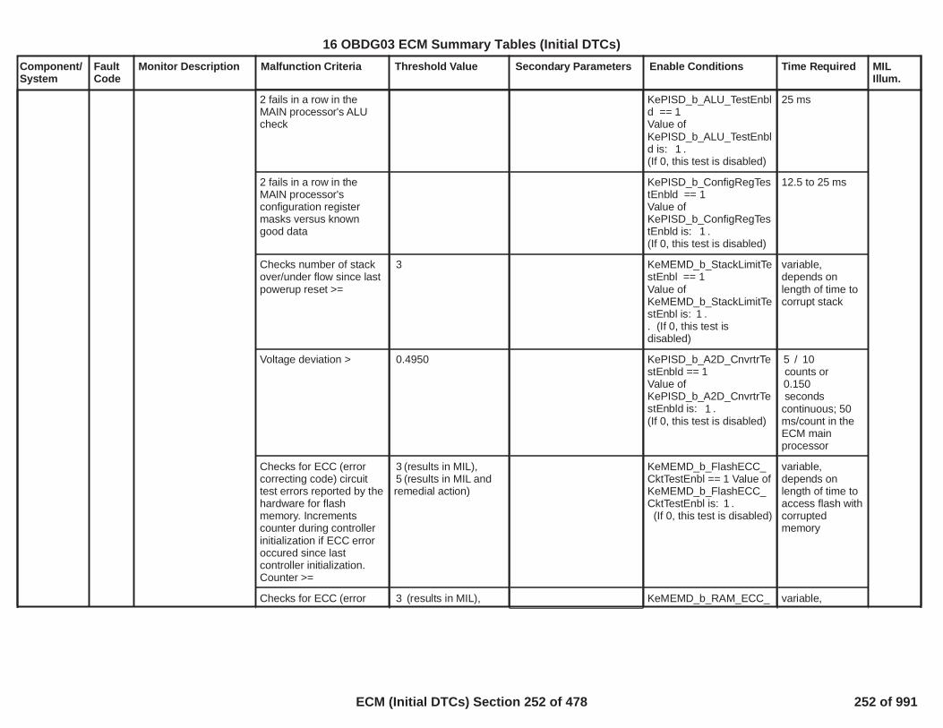
Component/System
FaultCode
Monitor Description Malfunction Criteria Threshold Value Secondary Parameters Enable Conditions Time Required MILIllum.
2 fails in a row in theMAIN processor's ALUcheck
KePISD_b_ALU_TestEnbld == 1Value ofKePISD_b_ALU_TestEnbld is: .1(If 0, this test is disabled)
25 ms
2 fails in a row in theMAIN processor'sconfiguration registermasks versus knowngood data
KePISD_b_ConfigRegTestEnbld == 1Value ofKePISD_b_ConfigRegTestEnbld is: .1(If 0, this test is disabled)
12.5 to 25 ms
Checks number of stackover/under flow since lastpowerup reset >=
3 KeMEMD_b_StackLimitTestEnbl == 1Value ofKeMEMD_b_StackLimitTestEnbl is: .1. (If 0, this test isdisabled)
variable,depends onlength of time tocorrupt stack
Voltage deviation > 0.4950 KePISD_b_A2D_CnvrtrTestEnbld == 1Value ofKePISD_b_A2D_CnvrtrTestEnbld is: .1(If 0, this test is disabled)
/5 10counts or0.150seconds
continuous; 50ms/count in theECM mainprocessor
Checks for ECC (errorcorrecting code) circuittest errors reported by thehardware for flashmemory. Incrementscounter during controllerinitialization if ECC erroroccured since lastcontroller initialization.Counter >=
(results in MIL),3(results in MIL and5
remedial action)
KeMEMD_b_FlashECC_CktTestEnbl == 1 Value ofKeMEMD_b_FlashECC_CktTestEnbl is: .1(If 0, this test is disabled)
variable,depends onlength of time toaccess flash withcorruptedmemory
Checks for ECC (error (results in MIL),3 KeMEMD_b_RAM_ECC_ variable,
254
16 OBDG03 ECM Summary Tables (Initial DTCs)
ECM (Initial DTCs) Section 252 of 478 252 of 991

Component/System
FaultCode
Monitor Description Malfunction Criteria Threshold Value Secondary Parameters Enable Conditions Time Required MILIllum.
correcting code) circuittest errors reported by thehardware for RAMmemory circuit.Increments counter duringcontroller initialization ifECC error occured sincelast controller initialization.Counter >=
(results in MIL and5remedial action)
CktTestEnbl == 1Value ofKeMEMD_b_RAM_ECC_CktTestEnbl is: .1(If 0, this test is disabled)
depends onlength of time towrite flash toRAMvariable,depends onlength of time towrite flash toRAM
MAIN processor DMAtransfer from Flash toRAM has 1 failure
KePISD_b_DMA_XferTestEnbld == 1Value ofKePISD_b_DMA_XferTestEnbld is:
.0(If 0, this test is disabled)
variable,depends onlength of time towrite flash toRAM
Safety critical software isnot executed in properorder.
>= 1 incorrectsequence.
Table, f(Core, Loop Time).See supporting tables:P0606_ProgramSequence Watch Enablef(Core, Loop Time)(If 0, this Loop Time test isdisabled)
Fail Table, f(LoopTime). Seesupportingtables:P0606_PSWSequence Fail f(Loop Time)/
Sample Table, f(Loop Time)Seesupportingtables:P0606_PSWSequenceSample f(LoopTime)
counts
50 ms/count inthe ECM mainprocessor
255
16 OBDG03 ECM Summary Tables (Initial DTCs)
ECM (Initial DTCs) Section 253 of 478 253 of 991

Component/System
FaultCode
Monitor Description Malfunction Criteria Threshold Value Secondary Parameters Enable Conditions Time Required MILIllum.
MAIN processordetermines a seed hasnot changed within aspecified time periodwithin the 50ms task.
Previous seed valueequals current seedvalue.
KePISD_b_SeedUpdKeyStorFltEnbl == 1Value ofKePISD_b_SeedUpdKeyStorFltEnbl is:
.1(If 0, this test is disabled)
Table, f(LoopTime). Seesupportingtables:P0606_LastSeed Timeout f(Loop Time)
256
16 OBDG03 ECM Summary Tables (Initial DTCs)
ECM (Initial DTCs) Section 254 of 478 254 of 991

Component/System
FaultCode
Monitor Description Malfunction Criteria Threshold Value Secondary Parameters Enable Conditions Time Required MILIllum.
Fuel PumpRelayControlCircuit Open
P0627 Diagnoses the fuelpump relay control highside driver circuit forcircuit faults
Voltage high during driveroff state (indicates opencircuit)
Open circuit: 200 K impedance
between signal andcontroller ground
Run/Crank Voltage
Engine Speed
Voltage volts11.00
RPM0
failures out of8samples10
250 ms / sample
Type B,2 Trips
Note: Incertaincontrollers P0629may alsoset (FuelPumpRelayControlShort toPower)
257
16 OBDG03 ECM Summary Tables (Initial DTCs)
ECM (Initial DTCs) Section 255 of 478 255 of 991
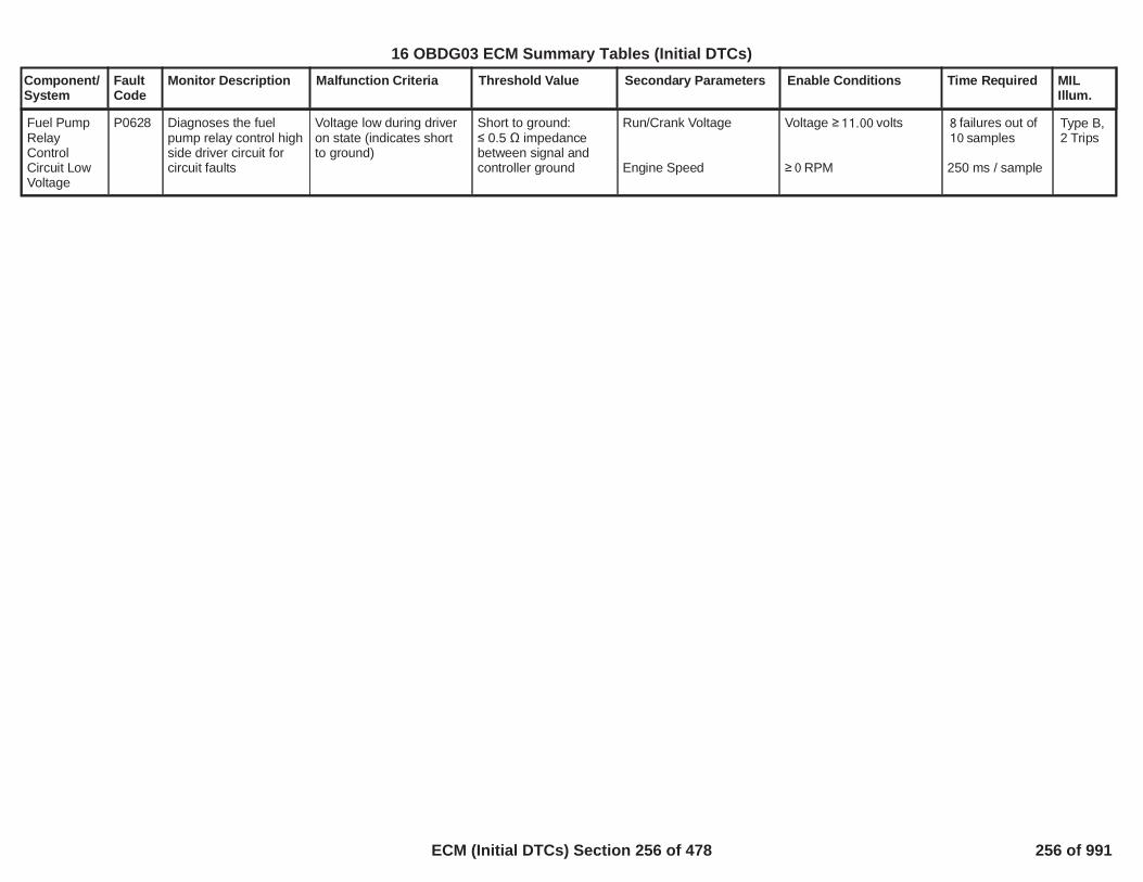
Component/System
FaultCode
Monitor Description Malfunction Criteria Threshold Value Secondary Parameters Enable Conditions Time Required MILIllum.
Fuel PumpRelayControlCircuit LowVoltage
P0628 Diagnoses the fuelpump relay control highside driver circuit forcircuit faults
Voltage low during driveron state (indicates shortto ground)
Short to ground: 0.5 impedance
between signal andcontroller ground
Run/Crank Voltage
Engine Speed
Voltage volts11.00
RPM0
failures out of8samples10
250 ms / sample
Type B,2 Trips
258
16 OBDG03 ECM Summary Tables (Initial DTCs)
ECM (Initial DTCs) Section 256 of 478 256 of 991

Component/System
FaultCode
Monitor Description Malfunction Criteria Threshold Value Secondary Parameters Enable Conditions Time Required MILIllum.
Fuel PumpRelayControlCircuit HighVoltage
P0629 Diagnoses the fuelpump relay control highside driver circuit forcircuit faults
Voltage high during driveroff state (indicates shortto power)
Short to power: 0.5 impedance
between signal andcontroller power
Run/Crank Voltage
Engine Speed
Voltage volts11.00
RPM0
failures out of8samples10
250 ms / sample
Type B,2 Trips
Note: Incertaincontrollers P0627may alsoset (FuelPumpRelayControlOpenCircuit)
259
16 OBDG03 ECM Summary Tables (Initial DTCs)
ECM (Initial DTCs) Section 257 of 478 257 of 991

Component/System
FaultCode
Monitor Description Malfunction Criteria Threshold Value Secondary Parameters Enable Conditions Time Required MILIllum.
InternalControlModule FuelInjectorControlPerformance
P062B This DTC Diagnosesthe internal fuel injctorcontrol module circuitfor circuit faults.
Internal ECU BoostVoltage
OR
Internal ECU BoostVoltage
OR
Driver Status
OR
Driver Status
>= Volts90
<= Volts40
= Not Ready
= Uninitialized
Battery Voltage >= or >=8 11
Enabled when a codeclear is not active or notexiting device controlEngine is not crankingPowertrain Relay Voltagewithin range
High Voltage -failures out160
of samples200
Low Voltage -failures out160
of samples200
Driver Status NotReady-
failures out160of samples200
Driver StatusUninitialized -Uninitializedstate for >=100counts
All at 12.5ms persample
Type A,1 Trips
260
16 OBDG03 ECM Summary Tables (Initial DTCs)
ECM (Initial DTCs) Section 258 of 478 258 of 991

Component/System
FaultCode
Monitor Description Malfunction Criteria Threshold Value Secondary Parameters Enable Conditions Time Required MILIllum.
HWIO reports that writingto NVM (at shutdown) willnot succeed
Diagnostic runsat controllerpower up.
PowertrainInternalControlModuleEEPROMError
P062F This DTC detects aNVM long termperformance.Indicatesthat the ECM hasdetected an internalprocessor integrity fault
Type B,2 Trips
HWIO reports theassembly calibrationintegrity check has failed
Diagnostic runsat controllerpower up.
261
16 OBDG03 ECM Summary Tables (Initial DTCs)
ECM (Initial DTCs) Section 259 of 478 259 of 991

Component/System
FaultCode
Monitor Description Malfunction Criteria Threshold Value Secondary Parameters Enable Conditions Time Required MILIllum.
VIN NotProgrammedorMismatched- EngineControlModule(ECM)
P0630 This DTC checks thatthe VIN is correctlywritten
At least one of theprogrammed VIN digits
= 00 or FF OBD ManufacturerEnable Counter
= 0 250 ms / testContinuous
Type A,1 Trips
262
16 OBDG03 ECM Summary Tables (Initial DTCs)
ECM (Initial DTCs) Section 260 of 478 260 of 991

Component/System
FaultCode
Monitor Description Malfunction Criteria Threshold Value Secondary Parameters Enable Conditions Time Required MILIllum.
5 VoltReference#1 Circuit
P0641 Detects a continuous orintermittent short on the5 volt reference circuit#1
ECM Vref1 <or ECM Vref1 >or the difference betweenECM filtered Vref1 andVref1 >
4.8265.074
0.0495
Run/Crank voltage >6.41
/40 80counts or0.2000sec continuous;
12.5 ms/count inmain processor
Type A,1 Trips
263
16 OBDG03 ECM Summary Tables (Initial DTCs)
ECM (Initial DTCs) Section 261 of 478 261 of 991

Component/System
FaultCode
Monitor Description Malfunction Criteria Threshold Value Secondary Parameters Enable Conditions Time Required MILIllum.
InternalControlModule O2SensorProcessorPerformanceBank 1) (Foruse withWRAF
P064D Diagnoses the WRAFinternal control modulefor faults.
B1S1 WRAF ASICindicates an internalcircuit fault.
The Controller statusinput from the ASIC isused to enable all WRAFdiagnostics (exceptP064D).
The Measure valid statusinput from the ASIC isused to enable ClosedLoop fuel control, P223Cand P223E.
Controller Status failcounts and MeasureValid fail counts areaccumulated todetermine fault status
No Active DTC's
Engine Run or Auto stop
Heater Warm-up delay
WRAF circuit diagnosticdelay since power up
P0131, P0132 or P223C
= True
= Complete
> = sec20.0
controller128status fail countsout of 160samples
OR
measure128valid fail countsout of 160samples
25 ms / sample
Continuous
Type B,2 Trips
264
16 OBDG03 ECM Summary Tables (Initial DTCs)
ECM (Initial DTCs) Section 262 of 478 262 of 991

Component/System
FaultCode
Monitor Description Malfunction Criteria Threshold Value Secondary Parameters Enable Conditions Time Required MILIllum.
MalfunctionIndicatorLamp (MIL)ControlCircuit(ODM) Open
P0650 Diagnoses themalfunction indicatorlamp control low sidedriver circuit for circuitfaults.
Voltage low during driveroff state (indicates opencircuit)
Open circuit: 200 K impedance
between signal andcontroller ground
Run/Crank Voltage
Remote Vehicle Start isnot active
Voltage volts11.00 failures out of1samples1
50 ms / sample
Type B,No MIL
NO MIL
Note: IncertaincontrollersP263Amay alsoset (MILControlShort toGround)
265
16 OBDG03 ECM Summary Tables (Initial DTCs)
ECM (Initial DTCs) Section 263 of 478 263 of 991

Component/System
FaultCode
Monitor Description Malfunction Criteria Threshold Value Secondary Parameters Enable Conditions Time Required MILIllum.
5 VoltReference#2 Circuit
P0651 Detects a continuous orintermittent short on the5 volt reference circuit#2
ECM Vref2 <or ECM Vref2 >or the difference betweenECM filtered Vref2 andVref2 >
4.8265.074
0.0495
Run/Crank voltage >6.41
/40 80counts or0.2000sec continuous;
12.5 ms/count inmain processor
Type A,1 Trips
266
16 OBDG03 ECM Summary Tables (Initial DTCs)
ECM (Initial DTCs) Section 264 of 478 264 of 991

Component/System
FaultCode
Monitor Description Malfunction Criteria Threshold Value Secondary Parameters Enable Conditions Time Required MILIllum.
PowertrainRelayControl(ODM) Open
P0685 Diagnoses thepowertrain relay controllow side driver circuitfor circuit faults
Voltage low during driveroff state (indicates opencircuit)
Open Circuit: 200 K ohms
impedance betweensignal and controllerground
Run/Crank Voltage Voltage volts11.00 failures out of8samples10
250 ms / sample
Type B,2 Trips
Note: Incertaincontrollers P0686may alsoset(PowertrainRelayControlShort toGround).
267
16 OBDG03 ECM Summary Tables (Initial DTCs)
ECM (Initial DTCs) Section 265 of 478 265 of 991

Component/System
FaultCode
Monitor Description Malfunction Criteria Threshold Value Secondary Parameters Enable Conditions Time Required MILIllum.
PowertrainRelayControl(ODM) Low
P0686 Diagnoses thepowertrain relay controllow side driver circuitfor circuit faults
Voltage low during driveroff state (indicates short-to-ground)
Short to ground: 0.5 impedance
between signal andcontroller ground
Run/Crank Voltage Voltage volts11.00 failures out of8samples10
250 ms / sample
Type B,2 Trips
Note: Incertaincontrollers P0685may alsoset(PowertrainRelayControlOpenCircuit).
268
16 OBDG03 ECM Summary Tables (Initial DTCs)
ECM (Initial DTCs) Section 266 of 478 266 of 991

Component/System
FaultCode
Monitor Description Malfunction Criteria Threshold Value Secondary Parameters Enable Conditions Time Required MILIllum.
PowertrainRelayControl(ODM) High
P0687 Diagnoses thepowertrain relay controllow side driver circuitfor circuit faults
Voltage high during driveron state (indicates shortto power)
Short to power: 0.5 impedance
between signal andcontroller power
Run/Crank Voltage Voltage volts11.00 failures out of8samples10
250 ms / sample
Type B,2 Trips
269
16 OBDG03 ECM Summary Tables (Initial DTCs)
ECM (Initial DTCs) Section 267 of 478 267 of 991

Component/System
FaultCode
Monitor Description Malfunction Criteria Threshold Value Secondary Parameters Enable Conditions Time Required MILIllum.
PowertrainRelayFeedbackCircuit High
P0690 This DTC is a check todetermine if thePowertrain relay isfunctioning properly.
Powertrain Relay Voltage >= volts will4.00increment the failcounter
Powertrain relaycommanded “OFF”
No active DTCs:
>= seconds2.00
PowertrainRelayStateOn_FA
failures out50of samples63
100ms / Sample
Type B,2 Trips
270
16 OBDG03 ECM Summary Tables (Initial DTCs)
ECM (Initial DTCs) Section 268 of 478 268 of 991

Component/System
FaultCode
Monitor Description Malfunction Criteria Threshold Value Secondary Parameters Enable Conditions Time Required MILIllum.
Cooling Fan1 RelayControlCircuit LowVoltage(ODM)
P0691 Diagnoses the coolingfan 1 relay control lowside driver circuit forcircuit faults
Voltage low during driveroff state (indicates short-to-ground)
Short to ground: 0.5 impedance
between signal andcontroller ground
Powertrain Relay Voltage Voltage volts11.00 failures out of50samples63
100 ms / sample
Type B,2 Trips
Note: Incertaincontrollers P0480may alsoset (Fan1 OpenCircuit).
271
16 OBDG03 ECM Summary Tables (Initial DTCs)
ECM (Initial DTCs) Section 269 of 478 269 of 991

Component/System
FaultCode
Monitor Description Malfunction Criteria Threshold Value Secondary Parameters Enable Conditions Time Required MILIllum.
Cooling Fan1 RelayControlCircuit HighVoltage(ODM)
P0692 Diagnoses the coolingfan 1 relay control lowside driver circuit forcircuit faults
Voltage high during driveron state (indicates shortto power)
Short to power: 0.5 impedance
between signal andcontroller power
Powertrain Relay Voltage Voltage volts11.00 failures out of50samples63
100 ms / sample
Type B,2 Trips
272
16 OBDG03 ECM Summary Tables (Initial DTCs)
ECM (Initial DTCs) Section 270 of 478 270 of 991

Component/System
FaultCode
Monitor Description Malfunction Criteria Threshold Value Secondary Parameters Enable Conditions Time Required MILIllum.
5 VoltReference#3 Circuit
P0697 Detects a continuous orintermittent short on the5 volt reference circuit#3
ECM Vref3 <or ECM Vref3 >or the difference betweenECM filtered Vref3 andVref3 >
4.8265.074
0.0495
Run/Crank voltage >6.41
/40 80counts or0.2000sec continuous;12.5 ms/count inmain processor
Type A,1 Trips
273
16 OBDG03 ECM Summary Tables (Initial DTCs)
ECM (Initial DTCs) Section 271 of 478 271 of 991

Component/System
FaultCode
Monitor Description Malfunction Criteria Threshold Value Secondary Parameters Enable Conditions Time Required MILIllum.
5 VoltReference#4 Circuit
P06A3 Detects a continuous orintermittent short on the5 volt reference circuit#4
ECM Vref4 <or ECM Vref4 >or the difference betweenECM filtered Vref4 andVref4 >
4.8265.074
0.0495
Run/Crank voltage >6.41
/40 80counts or0.2000sec continuous;
12.5 ms/count inmain processor
Type A,1 Trips
274
16 OBDG03 ECM Summary Tables (Initial DTCs)
ECM (Initial DTCs) Section 272 of 478 272 of 991
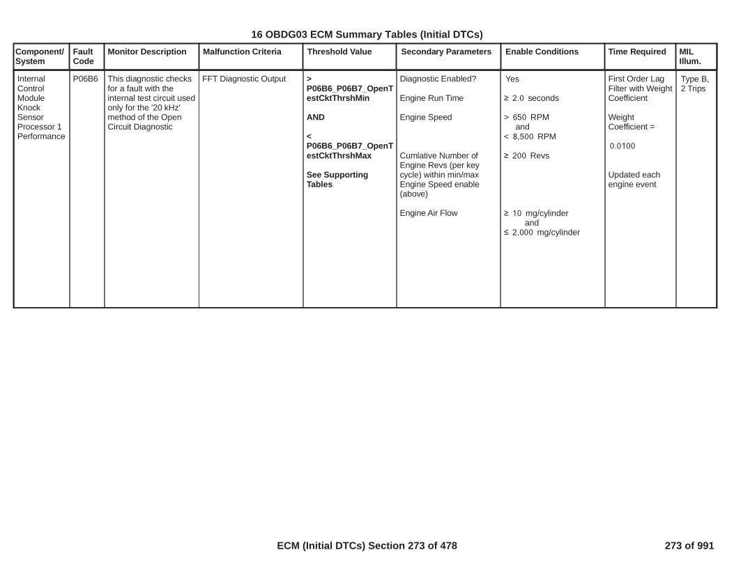
Component/System
FaultCode
Monitor Description Malfunction Criteria Threshold Value Secondary Parameters Enable Conditions Time Required MILIllum.
InternalControlModuleKnockSensorProcessor 1Performance
P06B6 This diagnostic checksfor a fault with theinternal test circuit usedonly for the '20 kHz'method of the OpenCircuit Diagnostic
FFT Diagnostic Output >P06B6_P06B7_OpenTestCktThrshMin
AND
<P06B6_P06B7_OpenTestCktThrshMax
See SupportingTables
Diagnostic Enabled?
Engine Run Time
Engine Speed
Cumlative Number ofEngine Revs (per keycycle) within min/maxEngine Speed enable(above)
Engine Air Flow
Yes
seconds2.0
> RPM650and
< RPM8,500
Revs200
mg/cylinder10and
mg/cylinder2,000
First Order LagFilter with WeightCoefficient
WeightCoefficient =
0.0100
Updated eachengine event
Type B,2 Trips
275
16 OBDG03 ECM Summary Tables (Initial DTCs)
ECM (Initial DTCs) Section 273 of 478 273 of 991
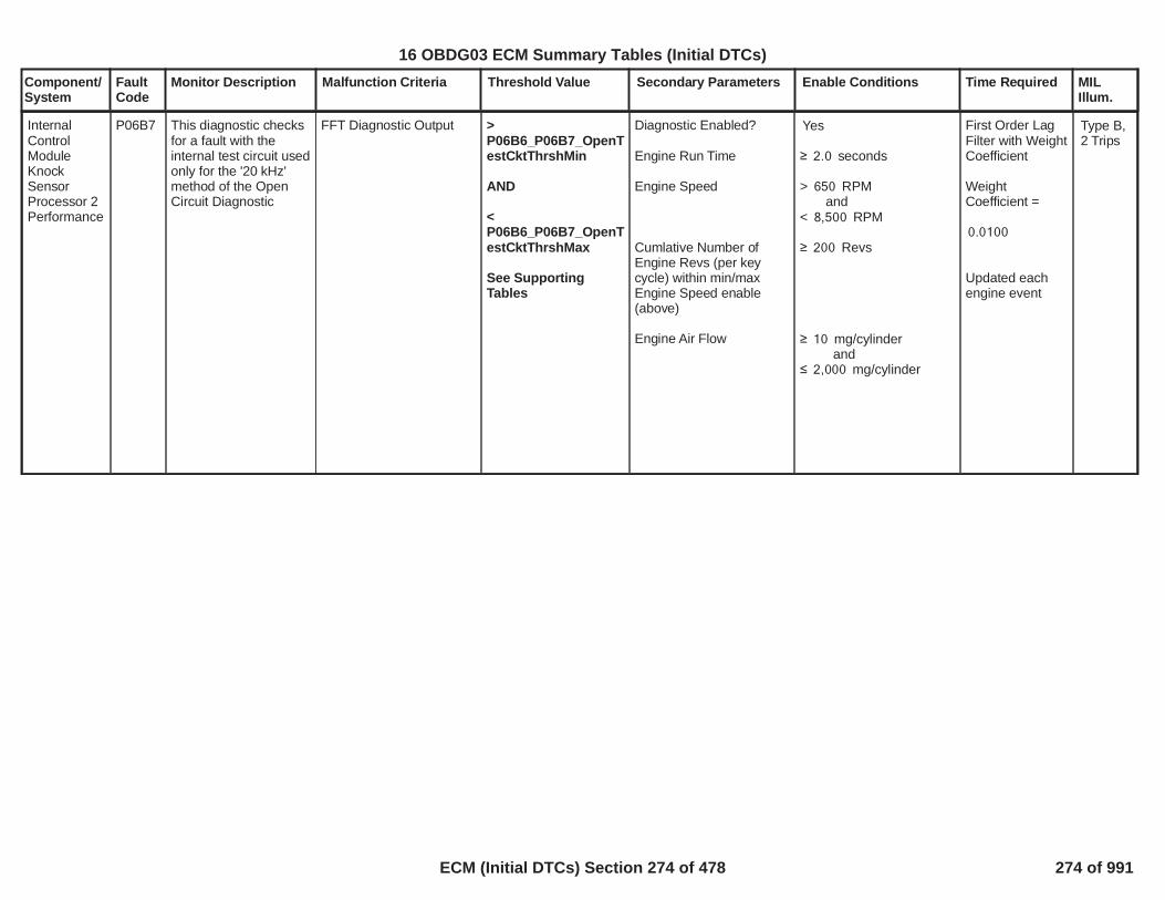
Component/System
FaultCode
Monitor Description Malfunction Criteria Threshold Value Secondary Parameters Enable Conditions Time Required MILIllum.
InternalControlModuleKnockSensorProcessor 2Performance
P06B7 This diagnostic checksfor a fault with theinternal test circuit usedonly for the '20 kHz'method of the OpenCircuit Diagnostic
FFT Diagnostic Output >P06B6_P06B7_OpenTestCktThrshMin
AND
<P06B6_P06B7_OpenTestCktThrshMax
See SupportingTables
Diagnostic Enabled?
Engine Run Time
Engine Speed
Cumlative Number ofEngine Revs (per keycycle) within min/maxEngine Speed enable(above)
Engine Air Flow
Yes
seconds2.0
> RPM650and
< RPM8,500
Revs200
mg/cylinder10and
mg/cylinder2,000
First Order LagFilter with WeightCoefficient
WeightCoefficient =
0.0100
Updated eachengine event
Type B,2 Trips
276
16 OBDG03 ECM Summary Tables (Initial DTCs)
ECM (Initial DTCs) Section 274 of 478 274 of 991

Component/System
FaultCode
Monitor Description Malfunction Criteria Threshold Value Secondary Parameters Enable Conditions Time Required MILIllum.
5 VoltReference#5 Circuit
P06D2 Detects a continuous orintermittent short on the5 volt reference circuit#5
ECM Vref5 <or ECM Vref5 >or the difference betweenECM filtered Vref5 andVref5 >
4.8265.074
0.0495
Run/Crank voltage >6.41
/40 80counts or0.2000sec continuous;
12.5 ms/count inmain processor
Type A,1 Trips
277
16 OBDG03 ECM Summary Tables (Initial DTCs)
ECM (Initial DTCs) Section 275 of 478 275 of 991

Component/System
FaultCode
Monitor Description Malfunction Criteria Threshold Value Secondary Parameters Enable Conditions Time Required MILIllum.
Two StageOil PumpControlCircuit Open
P06DA Diagnoses the twostage oil pump low sidedriver for open circuitfault
Voltage low during driveroff state (indicates anopen circuit)
Open Circuit 200 k impedance
between signal andcontroller ground
Diagnostic Status
Powertrain Relay Voltage
Run/Crank Active
Cranking State
Enabled
11.00
= True
= False
>= errors40out of 50samples.
Performed every100 msec
Type B,2 Trips
Note: IncertaincontrollersP06DBmay alsoset (TwoStageOilPumpControlCircuitShort ToGround)
278
16 OBDG03 ECM Summary Tables (Initial DTCs)
ECM (Initial DTCs) Section 276 of 478 276 of 991

Component/System
FaultCode
Monitor Description Malfunction Criteria Threshold Value Secondary Parameters Enable Conditions Time Required MILIllum.
Two StageOil PumpControlCircuit ShortTo Ground
P06DB Diagnoses the twostage oil pump low sidedriver for Short toGround circuit fault
Voltage low during driveroff state (indicates anshort circuit to Ground)
Short to Ground Circuit 0.5 impedance
between signal andcontroller ground
Diagnostic Status
Powertrain Relay Voltage
Run/Crank Active
Cranking State
Enabled
11.00
= True
= False
>= errors40out of 50samples.
Performed every100 msec
Type A,1 Trips
Note: IncertaincontrollersP06DAmay alsoset (TwoStageOilPumpControlCircuitOpen)
279
16 OBDG03 ECM Summary Tables (Initial DTCs)
ECM (Initial DTCs) Section 277 of 478 277 of 991

Component/System
FaultCode
Monitor Description Malfunction Criteria Threshold Value Secondary Parameters Enable Conditions Time Required MILIllum.
Two StageOil PumpControlCircuit ShortTo Power
P06DC Diagnoses the twostage oil pump low sidedriver for Short toPower circuit fault
Voltage low during driveron state (indicates anshort to power)
Short to Power 0.5 impedance
between signal andcontroller power
Diagnostic Status
Powertrain Relay Voltage
Run/Crank Active
Cranking State
Enabled
11.00
= True
= False
>= errors40out of 50samples.
Performed every100 msec
Type B,2 Trips
280
16 OBDG03 ECM Summary Tables (Initial DTCs)
ECM (Initial DTCs) Section 278 of 478 278 of 991

Component/System
FaultCode
Monitor Description Malfunction Criteria Threshold Value Secondary Parameters Enable Conditions Time Required MILIllum.
Fail from passing state:
Oil Pressure delta is lessthan a minimum deltapressure on a statechange and the measuredfiltered oil pressure isabove a threshold
Oil Pressure delta =ABS [ Filtered OilPressure at beginningof state change -filtered oil pressureafter seconds]1.5
Oil Pressure delta<P06DD_P06DE_OP_StateChangeMin
AND
Filtered Oil Pressure
(P0521_P06DD_P06DE_OP_HiStatePressure+P06DD_P06DE_OP_LoStatePressure) ÷ 2
(see P06DD details onSupporting Tables TabP06DD_P06DE_OP_StateChangeMinP0521_P06DD_P06DE_OP_HiStatePressureP06DD_P06DE_OP_LoStatePressure)
Common Criteria:
Two Stage Oil Pump isPresent
Engine Running
Ambient Air Pressure
Oil Aeration(= TRUE if engine speed> RPM for longer5,000than seconds)30.0
No active DTC's fordiagnsotic enable:
Check oil pump TFTKOas a diagnostic enablewhen Enabled.
No active DTC's forcontrol enable:
Active Criteria:One Sided PerformanceTest = Disabled
TRUE
seconds20.0
kPa70.0
FALSE
Fault bundles:MAF_SensorFAECT_Sensor_FAIAT_SensorFACrankSensor_FAEngOilPressureSensorCktFAAmbientAirDefaultEngOilTempFAOilPmpTFTKO
:Enabled OilPmpTFTKO
Fault bundles forEnabledcontrol disable :OilPmpTFTKOEngineTorqueEstInaccurateEngOilPressureSensorFAPowertrainRelayFaultCrankSensor_FAEngOilTempFA
Disabled
errors12out of 15samples.
Run once per tripor activiated bythe Passive Test
Two StageOil PumpControlCircuitPerformance- Two Sided
P06DD Diagnoses the twostage oil pump is stuckin the high pressurestate
Type B,2 Trips
281
16 OBDG03 ECM Summary Tables (Initial DTCs)
ECM (Initial DTCs) Section 279 of 478 279 of 991

Component/System
FaultCode
Monitor Description Malfunction Criteria Threshold Value Secondary Parameters Enable Conditions Time Required MILIllum.
Oil Pump in Low State
Modelled Oil Temperaturewithin range
Filtered Engine Speedwithin range
Delta Filtered EngineSpeed within a range
Engine Torque withinrange
Filtered Oil Pressurewithin range
> seconds1.5
deg C Oil Temp 70.0deg C115.0
RPM Filtered1,500Engine Speed 2,500RPM
ABS [Filtered RPM atbeginning of State change- Filtered RPM after 1.0seconds ] RPM150
P06DD_P06DE_MinEnableTorque_OP
Indicated RequestedEngine Torque
P06DD_P06DE_MaxEnableTorque_OP
(see P06DD details onSupporting Tables TabP06DD_P06DE_MinEnableTorque_OP
)P06DD_P06DE_MaxEnableTorque_OP
Filtered Engine OilPressure >P06DD_P06DE_MinOilPressThresh
(see P06DD details onSupporting Tables TabP06DD_P06DE_MinOilPressThresh)
282
16 OBDG03 ECM Summary Tables (Initial DTCs)
ECM (Initial DTCs) Section 280 of 478 280 of 991

Component/System
FaultCode
Monitor Description Malfunction Criteria Threshold Value Secondary Parameters Enable Conditions Time Required MILIllum.
Expected Oil PressureDelta within range
Passive Criteria:
Active Test Passed
Filtered Engine Speedwithin range
Modelled Oil Temperaturewithin range
Delta Filtered EngineSpeed within a range
Oil Pressure Deltawithin a range
kPa < ABS [25.0P0521_P06DD_P06DE_OP_HiStatePressure-
]P06DD_P06DE_OP_LoStatePressure< kPa200.0
TRUE
RPM Filtered1,500Engine Speed 4,500RPM
deg C Oil Temp 40.0deg C120.0
ABS [Filtered RPM atbeginning of State change- Filtered RPM after 1.50seconds ] RPM450
Oil Pressure Delta<P06DD_P06DE_OP_StateChangeMin(see P06DD details onSupporting Tables TabP06DD_P06DE_OP_StateChangeMin)
Fast Pass Condition
Oil Pressure delta is lessthan a minimum deltapressure on a statechange and the measuredfiltered oil pressure is
Oil Pressure delta =
ABS [ Filtered OilPressure at beginningof state change -
Common Criteria:
Two Stage Oil Pump isPresent
Engine Running
TRUE
seconds20.0
0 errorsout of 5samples.
Run once per tripor activiated bythe Passive Test
283
16 OBDG03 ECM Summary Tables (Initial DTCs)
ECM (Initial DTCs) Section 281 of 478 281 of 991

Component/System
FaultCode
Monitor Description Malfunction Criteria Threshold Value Secondary Parameters Enable Conditions Time Required MILIllum.
above a threshold filtered oil pressureafter seconds]1.5
Oil Pressure delta<P06DD_P06DE_OP_StateChangeMin
AND
Filtered Oil Pressure
(P0521_P06DD_P06DE_OP_HiStatePressure-P06DD_P06DE_OP_LoStatePressure) ÷ 2
(see P06DD details onSupporting Tables TabP06DD_P06DE_OP_StateChangeMinP0521_P06DD_P06DE_OP_HiStatePressureP06DD_P06DE_OP_LoStatePressure)
Ambient Air Pressure
Oil Aeration(= TRUE if engine speed> RPM for longer5,000than seconds)30.0
No active DTC's fordiagnsotic enable:
Check oil pump TFTKOas a diagnostic enablewhen Enabled.
No active DTC's forcontrol enable:
Active Criteria:One Sided PerformanceTest = Disabled
Oil Pump in Low State
Modelled Oil Temperaturewithin range
Filtered Engine Speedwithin range
kPa70.0
FALSE
Fault bundles:MAF_SensorFAECT_Sensor_FAIAT_SensorFAEngOilPressureSensorCktFAAmbientAirDefaultEngOilTempFAOilPmpTFTKOCrankSensor_FA
:Enabled OilPmpTFTKO
Fault bundles forEnabledcontrol disable :OilPmpTFTKOEngineTorqueEstInaccurateEngOilPressureSensorFAPowertrainRelayFaultCrankSensor_FAEngOilTempFA
Disabled
> seconds1.5
deg C Oil Temp 70.0deg C115.0
RPM Filtered1,500Engine Speed 2,500
284
16 OBDG03 ECM Summary Tables (Initial DTCs)
ECM (Initial DTCs) Section 282 of 478 282 of 991

Component/System
FaultCode
Monitor Description Malfunction Criteria Threshold Value Secondary Parameters Enable Conditions Time Required MILIllum.
Engine Torque withinrange
Delta Filtered EngineSpeed within a range
Filtered Oil Pressurewithin range
Expected Oil PressureDelta within range
RPM
P06DD_P06DE_MinEnableTorque_OP
Indicated RequestedEngine Torque
P06DD_P06DE_MaxEnableTorque_OP(see P06DD details onSupporting Tables TabP06DD_P06DE_MinEnableTorque_OP
)P06DD_P06DE_MaxEnableTorque_OP
ABS [Filtered RPM atbeginning of State change- Filtered RPM after 1.0seconds ] RPM150
Filtered Engine OilPressure >P06DD_P06DE_MinOilPressThresh(see P06DD details onSupporting Tables TabP06DD_P06DE_MinOilPressThresh)
kPa < ABS [25.0P0521_P06DD_P06DE_OP_HiStatePressure-
]P06DD_P06DE_OP_LoStatePressure< kPa200.0
285
16 OBDG03 ECM Summary Tables (Initial DTCs)
ECM (Initial DTCs) Section 283 of 478 283 of 991

Component/System
FaultCode
Monitor Description Malfunction Criteria Threshold Value Secondary Parameters Enable Conditions Time Required MILIllum.
Fail from a passing state:
Oil Pressure delta is lessthan a minimum deltapressure on a statechange and the measuredfiltered oil pressure isbelow a threshold
Oil Pressure delta =ABS [ Filtered OilPressure at beginningof state change -filtered oil pressureafter seconds]1.5
Oil Pressure delta<P06DD_P06DE_OP_StateChangeMin(see P06DE details onSupporting Tables Tab)
Filtered Oil Pressure
(
P0521_P06DD_P06DE_OP_HiStatePressure
-P06DD_P06DE_OP_LoStatePressure) ÷ 2(see P06DE details onSupporting Tables Tab)
Common Criteria:
Two Stage Oil Pump isPresent
Engine Running
Ambient Air Pressure
Oil Aeration(= TRUE if engine speed> RPM for longer5,000than seconds)30.0
No active DTC's fordiagnsotic enable:
Check oil pump TFTKOas a diagnostic enablewhen Enabled.
No active DTC's forcontrol enable:
Active Criteria:One Sided Performance
TRUE
seconds20.0
kPa70.0
FALSE
Fault bundles:MAF_SensorFAECT_Sensor_FAIAT_SensorFACrankSensor_FAEngOilPressureSensorCktFAAmbientAirDefaultEngOilTempFA
:Enabled OilPmpTFTKO
Fault bundles forEnabledcontrol disable :OilPmpTFTKOEngineTorqueEstInaccurateEngOilPressureSensorFAPowertrainRelayFaultCrankSensor_FAEngOilTempFA
Disabled
errors12out of 15samples.
Run once per tripor activiated bythe Passive Test
Two StageOil PumpControlCircuitStuckOn -Two Sided
P06DE Diagnoses the twostage oil pump is stuckin the low pressurestate
Type A,1 Trips
286
16 OBDG03 ECM Summary Tables (Initial DTCs)
ECM (Initial DTCs) Section 284 of 478 284 of 991

Component/System
FaultCode
Monitor Description Malfunction Criteria Threshold Value Secondary Parameters Enable Conditions Time Required MILIllum.
Test = Disabled
Oil Pump in Low State
Modelled Oil Temperaturewithin range
Filtered Engine Speedwithin range
Engine Torque withinrange
Delta Filtered EngineSpeed within a range
Filtered Oil Pressurewithin range
Expected Oil PressureDelta within range
> seconds1.5
deg C Oil Temp 70.0deg C115.0
RPM Filtered1,500Engine Speed 2,500RPM
P06DD_P06DE_MinEnableTorque_OP
Indicated RequestedEngine Torque
P06DD_P06DE_MaxEnableTorque_OP(see P06DE details onSupporting Tables Tab)
ABS [Filtered RPM atbeginning of State change- Filtered RPM after 1.0seconds ] RPM150
Filtered Engine OilPressure >P06DD_P06DE_MinOilPressThresh(see P06DD details onSupporting Tables Tab)
kPa < ABS [25.0P0521_P06DD_P06DE_OP_HiStatePressure-
]P06DD_P06DE_OP_LoStatePressure< kPa200.0
287
16 OBDG03 ECM Summary Tables (Initial DTCs)
ECM (Initial DTCs) Section 285 of 478 285 of 991

Component/System
FaultCode
Monitor Description Malfunction Criteria Threshold Value Secondary Parameters Enable Conditions Time Required MILIllum.
Passive Criteria:
Active Test Passed
Filtered Engine Speedwithin range
Modelled Oil Temperaturewithin range
Delta Filtered EngineSpeed within a range
Oil Pressure Delta<P06DD_P06DE_OP_StateChangeMin(see P06DE details onSupporting Tables Tab)
TRUE
RPM Filtered1,500Engine Speed 4,500RPM
deg C Oil Temp 40.0deg C120.0
ABS [Filtered RPM atbeginning of State change- Filtered RPM after
seconds ]1.50RPM450
TRUE
Fast Pass Condition
Oil Pressure delta is lessthan a minimum deltapressure on a statechange and the measuredfiltered oil pressure isbelow a threshold
Oil Pressure delta =ABS [ Filtered OilPressure at beginningof state change -filtered oil pressureafter seconds]1.5
Oil Pressure delta<
Common Criteria:
Two Stage Oil Pump isPresent
Engine Running
Ambient Air Pressure
Oil Aeration(= TRUE if engine speed
TRUE
seconds20.0
kPa70.0
FALSE
0 errorsout of 5 samples.
Run once per tripor activiated bythe Passive Test
288
16 OBDG03 ECM Summary Tables (Initial DTCs)
ECM (Initial DTCs) Section 286 of 478 286 of 991

Component/System
FaultCode
Monitor Description Malfunction Criteria Threshold Value Secondary Parameters Enable Conditions Time Required MILIllum.
P06DD_P06DE_OP_StateChangeMin(P06DD PerformanceTest Details onSupporting Tables Tab)
Filtered Oil Pressure
(
P0521_P06DD_P06DE_OP_HiStatePressure
-P06DD_P06DE_OP_LoStatePressure) / 2(P06DD PerformanceTest Details onSupporting Tables Tab)
> RPM for longer5,000than seconds)30.0
No active DTC's fordiagnsotic enable:
Check oil pump TFTKOas a diagnostic enablewhen Enabled.
No active DTC's forcontrol :
Active Criteria:One Sided PerformanceTest = Disabled
Oil Pump in Low State
Modelled Oil Temperaturewithin range
Filtered Engine Speedwithin range
Engine Torque withinrange
Fault bundles:MAF_SensorFAECT_Sensor_FAIAT_SensorFACrankSensor_FAEngOilPressureSensorCktFAAmbientAirDefaultEngOilTempFA
:Enabled OilPmpTFTKO
Fault bundles forEnabledcontrol disable :OilPmpTFTKOEngineTorqueEstInaccurateEngOilPressureSensorFAPowertrainRelayFaultCrankSensor_FAEngOilTempFA
Disabled
> seconds1.5
deg C Oil Temp 70.0deg C115.0
RPM Filtered1,500Engine Speed 2,500RPM
P06DD_P06DE_MinEnableTorque_OP
289
16 OBDG03 ECM Summary Tables (Initial DTCs)
ECM (Initial DTCs) Section 287 of 478 287 of 991
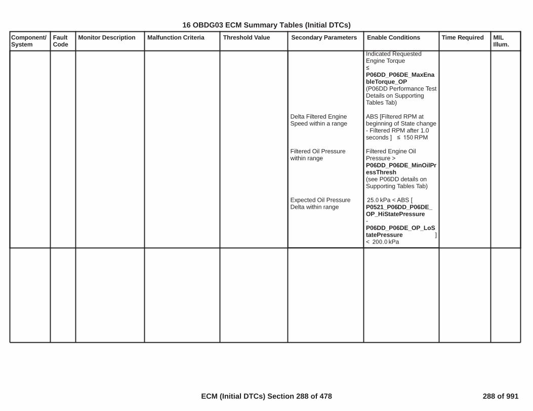
Component/System
FaultCode
Monitor Description Malfunction Criteria Threshold Value Secondary Parameters Enable Conditions Time Required MILIllum.
Delta Filtered EngineSpeed within a range
Filtered Oil Pressurewithin range
Expected Oil PressureDelta within range
Indicated RequestedEngine Torque
P06DD_P06DE_MaxEnableTorque_OP(P06DD Performance TestDetails on SupportingTables Tab)
ABS [Filtered RPM atbeginning of State change- Filtered RPM after 1.0seconds ] RPM150
Filtered Engine OilPressure >P06DD_P06DE_MinOilPressThresh(see P06DD details onSupporting Tables Tab)
kPa < ABS [25.0P0521_P06DD_P06DE_OP_HiStatePressure-
]P06DD_P06DE_OP_LoStatePressure< kPa200.0
290
16 OBDG03 ECM Summary Tables (Initial DTCs)
ECM (Initial DTCs) Section 288 of 478 288 of 991
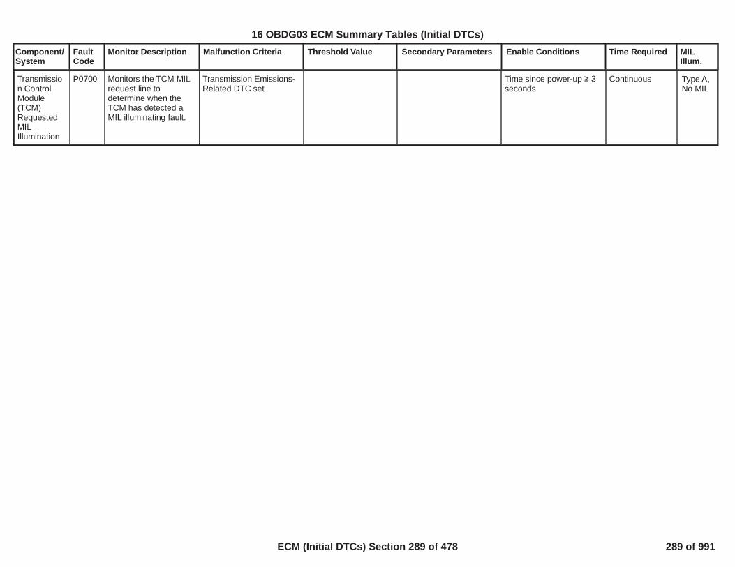
Component/System
FaultCode
Monitor Description Malfunction Criteria Threshold Value Secondary Parameters Enable Conditions Time Required MILIllum.
Transmission ControlModule(TCM)RequestedMILIllumination
P0700 Monitors the TCM MILrequest line todetermine when theTCM has detected aMIL illuminating fault.
Transmission Emissions-Related DTC set
Time since power-up 3seconds
Continuous Type A,No MIL
291
16 OBDG03 ECM Summary Tables (Initial DTCs)
ECM (Initial DTCs) Section 289 of 478 289 of 991

Component/System
FaultCode
Monitor Description Malfunction Criteria Threshold Value Secondary Parameters Enable Conditions Time Required MILIllum.
TractionControlTorqueRequestCircuit
P0856 Determines if torquerequest from theEBTCM is valid
Serial Communication 2’scomplement message -($1C7/$1C9 for enginetorque, $1CA/$1C6 foraxle torque)
ORSerial Communicationmessage ($1C7/$1C9 forengine torque, $1CA/$1C6 for axle torque)rolling count index value
ORToo many minimum limittorque request transitionsoccur from TRUE toFALSE to TRUE within atime period
Torque request greaterthan torque requestdiagnostic maximumthreshold
Message <> 2'scomplement ofmessage
Message rolling countvalue <> previousmessage rolling countvalue plus one
Requested torqueintervention typetoggles from notincreasing request toincreasing request
> Nm250for engine torquebased traction torquesystem,OR> Nm4,000for axle torque basedtraction torque system
Serial communication toEBTCM (U0108)
Power ModeEngine Running
Status of traction inGMLAN message ($4E9)
No loss ofcommunication
= Run= True
= Traction Present
>= failures8out of 10
Performed onevery receivedmessage
rolling count6failures out of
samples10
Performed onevery receivedmessage
>= multi-3transitions out of5 samples.
Performed every200 ms
>= out of 104samples
Performed onevery receivedmessage
Type C,No SVSSafetySpecialType C
292
16 OBDG03 ECM Summary Tables (Initial DTCs)
ECM (Initial DTCs) Section 290 of 478 290 of 991

Component/System
FaultCode
Monitor Description Malfunction Criteria Threshold Value Secondary Parameters Enable Conditions Time Required MILIllum.
Inlet AirflowSystemPerformance(single turbo)
P1101 Determines if there aremultiple air inductionproblems affectingairflow and/or manifoldpressure.
See tableP0101, P0106, P010B,P0121, P0236, P1101:Turbocharger IntakeFlow RationalityDiagnostic FailureMatrixfor combinationsof model failures that canset this DTC.
MAF model fails whenABS(Measured Flow –Modeled Air Flow) Filtered
MAP1 model fails whenABS(Measured MAP –MAP Model 1) Filtered
MAP2 model fails whenABS(Measured MAP –MAP Model 2) Filtered
MAP3 model fails whenABS(Measured MAP –MAP Model 3) Filtered
TIAP1 model fails whenABS(Measured TIAP –TIAP Model 1) Filtered
TPS model fails whenFiltered Throttle ModelError
TIAP Correlation modelfails whenHigh Engine Air Flow isTRUE ANDMeasured TIAP -
> grams/sec20.0
> kPa30.0
> kPa30.0
> kPa30.0
> kPa30.0
> kPa*(g/s)300
Engine SpeedEngine SpeedCoolant TempCoolant TempIntake Air TempIntake Air Temp
Minimum total weightfactor (all factorsmultiplied together)
See Residual WeightFactor tables.
>= RPM400<= RPM6,000> Deg C-7< Deg C130> Deg C-20< Deg C125
>= 0.50
Modeled Air Flow Errormultiplied byP0101, P0106, P010B,P0121, P012B, P0236,P1101: MAF1 ResidualWeight Factor based onRPMandP0101, P0106, P010B,P0121, P012B, P0236,P1101: MAF1 ResidualWeight Factor based onMAF Est
MAP Model 1 Errormultiplied byP0101, P0106, P0121,P012B, P0236, P1101:MAP1 Residual WeightFactor based on RPM
MAP Model 2 Errormultiplied byP0101, P0106, P0121,P012B, P0236, P1101:MAP2 Residual WeightFactor based on RPM
MAP Model 3 Errormultiplied by
Continuous
Calculation areperformed every12.5 msec
Type B,2 Trips
293
16 OBDG03 ECM Summary Tables (Initial DTCs)
ECM (Initial DTCs) Section 291 of 478 291 of 991

Component/System
FaultCode
Monitor Description Malfunction Criteria Threshold Value Secondary Parameters Enable Conditions Time Required MILIllum.
measured MAP - offsetas a function of enginespeedSee tableP0101, P0106, P0121,P0236, P1101: TIAP-MAP Correlation Offset
OR
Low Engine Air Flow isTRUE ANDMeasured TIAP -measured Baro - offset asa function of enginespeedSee tableP0101, P0106, P0121,P0236, P1101: TIAP-Baro Correlation Offset
TIAP Correlation is validwhenHigh Engine Air Flow hasbeen TRUE for a period oftimeORLow Engine Air Flow hasbeen TRUE for a period oftime
High Engine Air Flow isTRUE whenMass Air Flow
> kPa30.0
> kPa30.0
> seconds1.0
> seconds1.0
> a threshold in gmsec as a function ofengine speedSee tableP0101, P0106, P0121,P0236, P1101: TIAP-MAP Correlation MinAir Flow
No Active DTCs:
No Pending DTCs:
P0101, P0106, P0121,P012B, P0236, P1101:MAP3 Residual WeightFactor based on RPM
TIAP Model 1 Errormultiplied byP0101, P0106, P0121,P0236, P1101: TIAPResidual Weight Factorbased on RPM
Filtered Throttle ModelError multiplied byP0101, P0106, P0121,P012B, P0236, P1101:TPS Residual WeightFactor based on RPM
MAP_SensorCircuitFAEGRValvePerformance_FAMAF_SensorCircuitFACrankSensor_FAECT_Sensor_FAIAT_SensorFAMnfdTempSensorFATC_BoostPresSnsrCktFAAmbientAirDefault
EGRValve_FPECT_Sensor_Ckt_FPIAT_SensorCircuitFPMnfdTempSensorCktFP
294
16 OBDG03 ECM Summary Tables (Initial DTCs)
ECM (Initial DTCs) Section 292 of 478 292 of 991

Component/System
FaultCode
Monitor Description Malfunction Criteria Threshold Value Secondary Parameters Enable Conditions Time Required MILIllum.
ANDManifold Pressure
ANDFiltered Mass Air Flow -Mass Air Flow
Low Engine Air Flow isTRUE whenMass Air Flow
ANDManifold Pressure
ANDMass Air Flow - FilteredMass Air Flow
> a threshold in kPa asa function of enginespeedSee tableP0101, P0106, P0121,P0236, P1101: TIAP-MAP Correlation MinMAP
< gm/sec3.0
< a threshold in gmsec as a function ofengine speedSee tableP0101, P0106, P0121,P0236, P1101: TIAP-Baro Correlation MaxAir Flow
< a threshold in kPa asa function of enginespeedSee tableP0101, P0106, P0121,P0236, P1101: TIAP-Baro Correlation MaxMAP
< gm/sec2.0
295
16 OBDG03 ECM Summary Tables (Initial DTCs)
ECM (Initial DTCs) Section 293 of 478 293 of 991

Component/System
FaultCode
Monitor Description Malfunction Criteria Threshold Value Secondary Parameters Enable Conditions Time Required MILIllum.
Injector 1low sidecircuitshorted tohigh sidecircuit
P1248 This DTC DiagnosesInjector 1 enable lowside driver shorted tohigh side driver circuitfaults.
Voltage high across lowside and High side driversduring on state indicateslow side shorted to highside
Low side shorted toHigh Side:25 amp >= throughlow side driver
Battery VoltageEngine Run Time
>= Volts11>= Seconds5
P062B not FA or TFTK
10failures out of20samples
100 ms /sampleContinuous
Type A,1 Trips
296
16 OBDG03 ECM Summary Tables (Initial DTCs)
ECM (Initial DTCs) Section 294 of 478 294 of 991

Component/System
FaultCode
Monitor Description Malfunction Criteria Threshold Value Secondary Parameters Enable Conditions Time Required MILIllum.
Injector 2low sidecircuitshorted tohigh sidecircuit
P1249 This DTC DiagnosesInjector 2 enable lowside driver shorted tohigh side driver circuitfaults.
Voltage high across lowside and High side driversduring on state indicateslow side shorted to highside
Low side shorted toHigh Side:25 amp >= throughlow side driver
Battery VoltageEngine Run Time
>= Volts11>= Seconds5
P062B not FA or TFTK
10failures out of20samples
100 ms /sampleContinuous
Type A,1 Trips
297
16 OBDG03 ECM Summary Tables (Initial DTCs)
ECM (Initial DTCs) Section 295 of 478 295 of 991

Component/System
FaultCode
Monitor Description Malfunction Criteria Threshold Value Secondary Parameters Enable Conditions Time Required MILIllum.
Injector 3low sidecircuitshorted tohigh sidecircuit
P124A This DTC DiagnosesInjector 3 enable lowside driver shorted tohigh side driver circuitfaults.
Voltage high across lowside and High side driversduring on state indicateslow side shorted to highside
Low side shorted toHigh Side:25 amp >= throughlow side driver
Battery VoltageEngine Run Time
>= Volts11>= Seconds5
P062B not FA or TFTK
10failures out of20samples
100 ms /sampleContinuous
Type A,1 Trips
298
16 OBDG03 ECM Summary Tables (Initial DTCs)
ECM (Initial DTCs) Section 296 of 478 296 of 991

Component/System
FaultCode
Monitor Description Malfunction Criteria Threshold Value Secondary Parameters Enable Conditions Time Required MILIllum.
Injector 4low sidecircuitshorted tohigh sidecircuit
P124B This DTC DiagnosesInjector 4 enable lowside driver shorted tohigh side driver circuitfaults.
Voltage high across lowside and High side driversduring on state indicateslow side shorted to highside
Low side shorted toHigh Side:25 amp >= throughlow side driver
Battery VoltageEngine Run Time
>= Volts11>= Seconds5
P062B not FA or TFTK
10failures out of20samples
100 ms /sampleContinuous
Type A,1 Trips
299
16 OBDG03 ECM Summary Tables (Initial DTCs)
ECM (Initial DTCs) Section 297 of 478 297 of 991

Component/System
FaultCode
Monitor Description Malfunction Criteria Threshold Value Secondary Parameters Enable Conditions Time Required MILIllum.
Fuel PumpDriver OverTemperature
P1255 To detect if an internalfuel pump driver over-temperature conditionexists under normaloperating conditions
Fuel Pump Driver CircuitBoard temperature( FP DriverOvertemperatureenumeration)
T>= 160 degC( Fu Pmp Pwr Modsmart device reportsFaulted, Not Faulted orIndeterminate)
a) FPPM configurationKeFRPR_e_ChassisFuelPresSysType
b) DiagnosticKeFRPR_b_FPPM_OvertempDiagEnbld
c] FPPM Driver StatusAlive Rolling CountSample Faulted
d] Diagnostic feedbackreceived
e] System Voltage
a) == CeFRPR_e_ECM_FPPM_Sys
b) == TRUE
c] <> TRUE
d] == TRUE
e] 9V < System V < 32V
3 failures / 15samples
1 sample / 12.5millisec
Type B,2 Trips
300
16 OBDG03 ECM Summary Tables (Initial DTCs)
ECM (Initial DTCs) Section 298 of 478 298 of 991

Component/System
FaultCode
Monitor Description Malfunction Criteria Threshold Value Secondary Parameters Enable Conditions Time Required MILIllum.
Fuel PumpDriverModule-IgnitionSwitch Run/StartPositionCircuit Low
P129D To detect if the Run/Start position circuitvoltage is short to low /open
FPPM Run_Crank Activestatus
<> ECM Run_CrankActive status
a) FPPM configurationKeFRPR_e_ChassisFuelPresSysTypeb) DiagnosticKeFRPR_b_FPPM_RunCrnkRatlEnbldc) FPPM Control StatusAlive Rolling Count resultd) Diagnostic feedbackreceivede) System Voltage
a) ==CeFRPR_e_ECM_FPPM_Sysb) == TRUEc) == Validd) == TRUEe) >= 0.0 v
64 failures / 80samples
1 sample / 12.5millisec
Type B,2 Trips
301
16 OBDG03 ECM Summary Tables (Initial DTCs)
ECM (Initial DTCs) Section 299 of 478 299 of 991

Component/System
FaultCode
Monitor Description Malfunction Criteria Threshold Value Secondary Parameters Enable Conditions Time Required MILIllum.
FPPM Received DutyCycle Rolling Count
<> Transmitted DutyCycle Rolling Count( ECM)( Fu Pmp Pwr Modsmart device reportsFaulted, Not Faulted orIndeterminate teststate)
a) FPPM configurationKeFRPR_e_ChassisFuelPresSysTypeb) Fault statedetermination enabledc) FPPM Received DutyCycle Count resultd) FPPM Diagnosticfeedback receivede) CAN communicationf) System Voltage
a) ==CeFRPR_e_ECM_FPPM_Sysb) == TRUEc) == Validd) == TRUEe) == Validf) 9v < Sys Voltage > 32v
64 failures / 80samples
1 sample / 12.5millisec
Fuel PumpDriverControlModuleSignalMessageCounterIncorrect
P129E To detect if thecommand messagereceived as serial datafrom the engine controlmodule is valid
Type B,2 Trips
FPPM Received DutyCycle Protection Value
<> Transmitted DutyCycle Protection Value( ECM)( Fu Pmp Pwr Modsmart device reportsFaulted, Not Faulted orIndeterminate teststate)
a) FPPM configurationKeFRPR_e_ChassisFuelPresSysTypeb) Fault statedetermination enabledc) FPPM Received DutyCycle Protection Valueresultd) FPPM Diagnosticfeedback receivede) CAN communicationf) System Voltage
a) ==CeFRPR_e_ECM_FPPM_Sysb) == TRUEc) == Validd) == TRUEe) == Validf) 9v < Sys Voltage > 32v
64 failures / 80samples
1 sample / 12.5millisec
302
16 OBDG03 ECM Summary Tables (Initial DTCs)
ECM (Initial DTCs) Section 300 of 478 300 of 991

Component/System
FaultCode
Monitor Description Malfunction Criteria Threshold Value Secondary Parameters Enable Conditions Time Required MILIllum.
Fuel PumpDriverControlModuleEnableCircuitPerformance
P12A6 To detect a drivercontrol circuit signalstuck in normaloperating range
FPPM Fuel ControlEnable Active boolean
<> Fuel Control Enablevariable (ECM)
a) FPPM configurationKeFRPR_e_ChassisFuelPresSysTypeb) DiagnosticKeFRPR_b_FPPM_FuelCntrlEnblEnbldc) FPPM Control DataRolling Count resultd) Diagnostic feedbackreceivede) System Voltage
a) ==CeFRPR_e_ECM_FPPM_Sysb) == TRUEc) == Validd) == TRUEe) >= 9.0 v
40 failures / 80samples
1 sample / 12.5millisec
Type A,1 Trips
303
16 OBDG03 ECM Summary Tables (Initial DTCs)
ECM (Initial DTCs) Section 301 of 478 301 of 991

Component/System
FaultCode
Monitor Description Malfunction Criteria Threshold Value Secondary Parameters Enable Conditions Time Required MILIllum.
FPPM Control StatusAlive Rolling Count
<> ECM Control StatusAlive Rolling Count( Fu Pmp Pwr Modsmart device reportsFaulted, Not Faulted orIndeterminate teststate)
a) FPPM configurationKeFRPR_e_ChassisFuelPresSysTypeb) Fault statedetermination enabledc) FPPM Diagnosticfeedback received
a) ==CeFRPR_e_ECM_FPPM_Sysb) == TRUEc) == TRUE
64 failures / 80samples
1 sample / 12.5millisec
Fuel PumpControlStatusSignalMessageCounterIncorrect
P12A8 To detect if the controlstatus messagetransmitted as serialdata from the drivercontrol module is valid
Type B,2 Trips
FPPM PowerConsumption Alive RollingCount
<> ECM PowerConsumption AliveRolling Count( Fu Pmp Pwr Modsmart device reportsFaulted, Not Faulted orIndeterminate teststate)
a) FPPM configurationKeFRPR_e_ChassisFuelPresSysTypeb) Fault statedetermination enabledc) FPPM Diagnosticfeedback received
a) ==CeFRPR_e_ECM_FPPM_Sysb) == TRUEc) == TRUE
64 failures / 80samples
1 sample / 12.5millisec
FPPM Driver Status AliveRolling Count
<> ECM Driver StatusAlive Rolling Count( Fu Pmp Pwr Modsmart device reportsFaulted, Not Faulted orIndeterminate teststate)
a) FPPM configurationKeFRPR_e_ChassisFuelPresSysTypeb) Fault statedetermination enabledc) FPPM Diagnosticfeedback received
a) ==CeFRPR_e_ECM_FPPM_Sysb) == TRUEc) == TRUE
64 failures / 80samples
1 sample / 12.5millisec
FPPM Hardware StatusAlive Rolling Count
<> ECM HardwareStatus Alive RollingCount( Fu Pmp Pwr Modsmart device reportsFaulted, Not Faulted orIndeterminate teststate)
a) FPPM configurationKeFRPR_e_ChassisFuelPresSysTypeb) Fault statedetermination enabledc) FPPM Diagnosticfeedback received
a) ==CeFRPR_e_ECM_FPPM_Sysb) == TRUEc) == TRUE
64 failures / 80samples
1 sample / 12.5millisec
304
16 OBDG03 ECM Summary Tables (Initial DTCs)
ECM (Initial DTCs) Section 302 of 478 302 of 991

Component/System
FaultCode
Monitor Description Malfunction Criteria Threshold Value Secondary Parameters Enable Conditions Time Required MILIllum.
Ignition CoilPositiveVoltageCircuitGroup 1 ** SIDI ONLY* *
P135A This diagnostic checksfor voltage supply tothe Ignition Coils(applicable only forSIDI applications)
Common Enable Criteria
Ignition Module SupplyVoltage.
Three possible powersupply sources for IgnitionCoils (only 1 used):Case 1: BatteryCase 2: Ignition Run/
CrankCase 3: PT Relay
Case Specific EnableCriteria
< 2.5 Volts
Ignition Coil PowerSource =
(see correspondingcase specific enablecriteria below)
Case 1: Battery
Case 2: Ignition Run/Crank
Case 3: PT Relay
Diagnostic Enabled?
PT Relay
Delay starting at Key-On
Ignition Run/CrankVoltage
PT Relay Voltage
Yes
Engine Revs5
> volts5.0
> volts11.0
Failures50out ofSamples63
6.25 msec rate
Type A,1 Trips
305
16 OBDG03 ECM Summary Tables (Initial DTCs)
ECM (Initial DTCs) Section 303 of 478 303 of 991

Component/System
FaultCode
Monitor Description Malfunction Criteria Threshold Value Secondary Parameters Enable Conditions Time Required MILIllum.
Cold StartEmissionsReductionSystem Fault
P1400 Model based testcomputes power fromexhaust flow andthermal energyresulting from elevatedidle speed and retardedspark advance.Detects if the cold startemission reductionsystem has failedresulting in thedelivered power beingout of range.
Average desiredaccumulated exhaustpower - Average actualaccumulated exhaustpower(too much energydelivered to catalyst)
Average desiredaccumulated exhaustpower - Average actualaccumulated exhaustpower(too little energy deliveredto catalyst)
(EWMA filtered)
Average Power = outputofP1400_EngineSpeedResidual_Table* output ofP1400_SparkResidual_TableNOTE: Desiredaccumulated power woulduse the desired catalystlight off spark and desiredengine speed and theactual accumuated powerwould use the finalcommanded spark andactual engine speed.Refer to the SupportingTables for details
< -32.00KJ/s (high RPM failuremode)
> 4.00KJ/s(low RPM failuremode)
To enable the diagnostic,the Cold Start EmissionReduction Strategy mustbe Active per thefollowing:
Catalyst TemperatureANDEngine CoolantANDEngine CoolantANDBarometric Pressure
The Cold Start EmissionReduction strategy mustnot be exiting. Thestrategy will exit per thefollowing:
Catalyst TemperatureANDEngine Run Time
OR
Engine Run Time
OR
Barometric Pressure
< degC300.00
> degC-12.00
<= degC56.00
>= KPa78.00
>= degC800.00
>= seconds22.00
>P050D_P1400_CatalystLightOffExtendedEngineRunTimeExit
This Extended Enginerun time exit is a functionof percent ethanol andCatmonsNormRatioEWMA. Referto "Supporting Tables" fordetails.
< KPa78.00
Runs once pertrip when thecold startemissionreductionstrategy is active
Frequency:100ms Loop
Test completesafter8seconds ofaccumulatedqualified data.
EWMABased -Type A,1 Trips
16 OBDG03 ECM Summary Tables (Initial DTCs)
ECM (Initial DTCs) Section 304 of 478 304 of 991

Component/System
FaultCode
Monitor Description Malfunction Criteria Threshold Value Secondary Parameters Enable Conditions Time Required MILIllum.
Other Enable Criteria:
OBD ManufacturerEnable Counter
Vehicle Speed
Allow diagnostic tocalculate residual in anoff-idle state. If the valueof the OffIdleEnable isequal to 1 then the"DriverOffAccelPedal" willnot be checked.However, if the value ofOffIdleEnable is 0 thendriver must be off theaccel pedal
A change in throttleposition (tip-in/tip-out) willinitiate a delay in thecalculation of the averagequalified residual value.Therefore when the:
Pedal Close Delay Timer
the diagnostic willcontinue the calculation.
A change in gear willinitiate a delay in thecalculation of the averagequalified residual value to
0
< MPH1.86
0
(A value of 1 allowsdiagnostic to run andcalculate the residualwhile off idle. A value of 0requires calculation of theresidual at idle)
> seconds5.00
16 OBDG03 ECM Summary Tables (Initial DTCs)
ECM (Initial DTCs) Section 305 of 478 305 of 991

Component/System
FaultCode
Monitor Description Malfunction Criteria Threshold Value Secondary Parameters Enable Conditions Time Required MILIllum.
allow time for the actualengine speed and actualfinal commanded spark toachieve their desiredvalues. Therefore, whenthe:
Gear Shift Delay Timer
the diagnostic willcontinue the calculation
For Manual Transmissionvehicles:
Clutch Pedal Position
Clutch Pedal Position
The diagnostic will delaycalculation of the residualvalue and potentiallyweight the residualcalculation differentlybased on engine run time.This is to ensure thediagnostic is operating inidle speed control as wellas during the peakcatalyst light off period.
The time weighting factormust be :
> seconds1.50
> %88.00
< %16.00
> 0These are scalar valuesthat are a function ofengine run time. Refer to
16 OBDG03 ECM Summary Tables (Initial DTCs)
ECM (Initial DTCs) Section 306 of 478 306 of 991
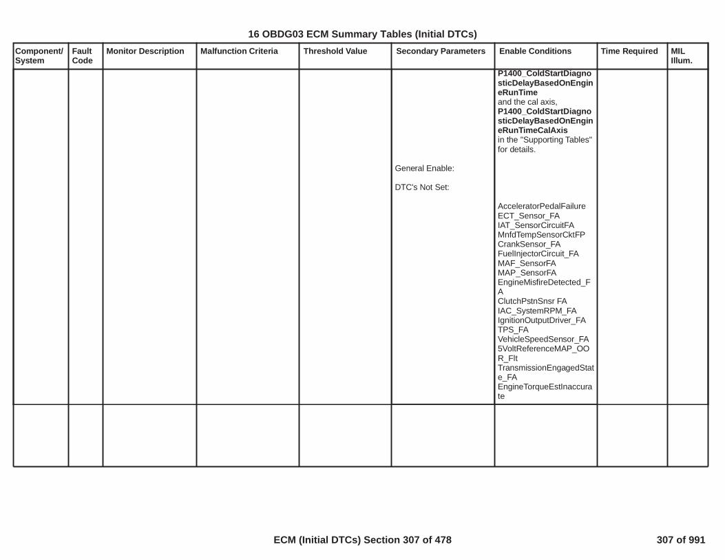
Component/System
FaultCode
Monitor Description Malfunction Criteria Threshold Value Secondary Parameters Enable Conditions Time Required MILIllum.
General Enable:
DTC's Not Set:
P1400_ColdStartDiagnosticDelayBasedOnEngineRunTimeand the cal axis,P1400_ColdStartDiagnosticDelayBasedOnEngineRunTimeCalAxisin the "Supporting Tables"for details.
AcceleratorPedalFailureECT_Sensor_FAIAT_SensorCircuitFAMnfdTempSensorCktFPCrankSensor_FAFuelInjectorCircuit_FAMAF_SensorFAMAP_SensorFAEngineMisfireDetected_FAClutchPstnSnsr FAIAC_SystemRPM_FAIgnitionOutputDriver_FATPS_FAVehicleSpeedSensor_FA5VoltReferenceMAP_OOR_FltTransmissionEngagedState_FAEngineTorqueEstInaccurate
16 OBDG03 ECM Summary Tables (Initial DTCs)
ECM (Initial DTCs) Section 307 of 478 307 of 991

Component/System
FaultCode
Monitor Description Malfunction Criteria Threshold Value Secondary Parameters Enable Conditions Time Required MILIllum.
Transmission EngineSpeedRequestCircuit
P150C Determines if enginespeed request from theTCM is valid
Serial Communicationrolling count value
Transmission enginespeed protection
+ 1 from previous$19D message(PTEI3)
not equal to 2'scomplement oftransmission enginespeed request +Transmission aliverolling count
Diagnostic enable bit
Engine run time
# of Protect Errors
# of Alive Rolling Errors
No idle diagnostic506/507 code
No Serial communicationloss to TCM
Engine Running
Power mode
1
sec0.50
protect errors within12the sample period 20
rolling count errors out6of 10 samples
IAC_SystemRPM_FA
(U0101)
= TRUE
Run Crank Active
Diagnostic runsin 12.5 ms loop
Type B,2 Trips
310
16 OBDG03 ECM Summary Tables (Initial DTCs)
ECM (Initial DTCs) Section 308 of 478 308 of 991

Component/System
FaultCode
Monitor Description Malfunction Criteria Threshold Value Secondary Parameters Enable Conditions Time Required MILIllum.
Steady StateActuationFault
P1516 Detect an inablity tomaintain a steady statethrottle position
The absolute differencebetween desired andindicated throttle positionis >
percent2.00
Run/Crank voltage >6.41
Ignition voltage failure isfalse (P1682)
TPS minimum learn is notactive and Throttle isbeing ControlledThrottle is considered in asteadystate conditionwhen the desired throttleposition over a 12.5 msperiod is < percent0.25for a settling time period >
s4.00
0.49ms
Type B,2 Trips
311
16 OBDG03 ECM Summary Tables (Initial DTCs)
ECM (Initial DTCs) Section 309 of 478 309 of 991
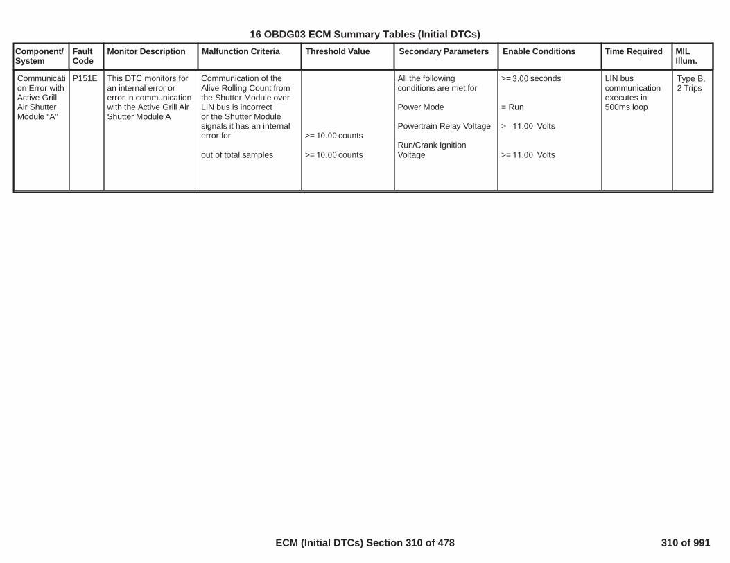
Component/System
FaultCode
Monitor Description Malfunction Criteria Threshold Value Secondary Parameters Enable Conditions Time Required MILIllum.
Communication Error withActive GrillAir ShutterModule “A”
P151E This DTC monitors foran internal error orerror in communicationwith the Active Grill AirShutter Module A
Communication of theAlive Rolling Count fromthe Shutter Module overLIN bus is incorrector the Shutter Modulesignals it has an internalerror for
out of total samples
>= counts10.00
>= counts10.00
All the followingconditions are met for
Power Mode
Powertrain Relay Voltage
Run/Crank IgnitionVoltage
>= seconds3.00
= Run
>= Volts11.00
>= Volts11.00
LIN buscommunicationexecutes in500ms loop
Type B,2 Trips
312
16 OBDG03 ECM Summary Tables (Initial DTCs)
ECM (Initial DTCs) Section 310 of 478 310 of 991

Component/System
FaultCode
Monitor Description Malfunction Criteria Threshold Value Secondary Parameters Enable Conditions Time Required MILIllum.
AdaptiveCruiseControlSignalCircuit
P1553 Detects rolling count orprotection value errorsin Adaptive CruiseControl Axle TorqueCommand serial datasignal
If x of y rolling count /protection value faultsoccur, disable adaptivecruise control for durationof fault
Adaptive Cruise ControlCommand Serial DataError Diagnostic Enable
1.00 10/16counts
MIL:Type C,No SVS
313
16 OBDG03 ECM Summary Tables (Initial DTCs)
ECM (Initial DTCs) Section 311 of 478 311 of 991

Component/System
FaultCode
Monitor Description Malfunction Criteria Threshold Value Secondary Parameters Enable Conditions Time Required MILIllum.
CruiseControlSwitch StateUndertermined
P155A Detects when cruiseswitch state cannot bedetermined, such aslow voltage conditions
cruise switch stateremains undetermined forgreater than a calibratabletime
fail continuouslyfor greater than3.0seconds
MIL:Type C,No SVS
314
16 OBDG03 ECM Summary Tables (Initial DTCs)
ECM (Initial DTCs) Section 312 of 478 312 of 991

Component/System
FaultCode
Monitor Description Malfunction Criteria Threshold Value Secondary Parameters Enable Conditions Time Required MILIllum.
DC/DCConverterActuatorVoltageSignalMessageCounterIncorrect
P155E This DTC monitors foran error incommunication with theDC/DC ConverterActuator Voltage Signal
Communication of theAlive Rolling Count orProtection Value from theDC/DC Converter overCAN bus is incorrectfor
out of total samples
>= counts10
>= counts10
All the followingconditions are met for
Power Mode
Powertrain Relay Voltage
Run/Crank IgnitionVoltage
>= seconds3.00
= Run
>= Volts11.00
>= Volts11.00
Executes in10ms loop.
Type B,2 Trips
315
16 OBDG03 ECM Summary Tables (Initial DTCs)
ECM (Initial DTCs) Section 313 of 478 313 of 991

Component/System
FaultCode
Monitor Description Malfunction Criteria Threshold Value Secondary Parameters Enable Conditions Time Required MILIllum.
DC/DCConverterPerformanceSignalMessageCounterIncorrect
P155F This DTC monitors foran error incommunication with theDC/DC ConverterInternal Health Signal
Communication of theAlive Rolling Count orProtection Value from theDC/DC Converter overCAN bus is incorrectfor
out of total samples
>=counts10
>=counts10
All the followingconditions are met for
Power Mode
Powertrain Relay Voltage
Run/Crank IgnitionVoltage
>=seconds3.00
= Run
>=Volts11.00
>=Volts11.00
Executes in25ms loop.
Type B,2 Trips
316
16 OBDG03 ECM Summary Tables (Initial DTCs)
ECM (Initial DTCs) Section 314 of 478 314 of 991

Component/System
FaultCode
Monitor Description Malfunction Criteria Threshold Value Secondary Parameters Enable Conditions Time Required MILIllum.
DC/DCConverterIgnitionSwitch Run/StartPositionSignalMessageCounterIncorrect
P156D This DTC monitors foran error incommunication with theDC/DC Converter Run/Crank Terminal StatusSignal
Communication of theAlive Rolling Count orProtection Value from theDC/DC Converter overCAN bus is incorrectfor
out of total samples
>= counts10
>= counts10
All the followingconditions are met for
Power Mode
Powertrain Relay Voltage
Run/Crank IgnitionVoltage
>=seconds3.00
= Run
>=Volts11.00
>=Volts11.00
Executes in10ms loop.
Type B,2 Trips
317
16 OBDG03 ECM Summary Tables (Initial DTCs)
ECM (Initial DTCs) Section 315 of 478 315 of 991

Component/System
FaultCode
Monitor Description Malfunction Criteria Threshold Value Secondary Parameters Enable Conditions Time Required MILIllum.
DC/DCConverterCrankControlSignalMessageCounterIncorrect
P156E This DTC monitors foran error incommunication with theDC/DC ConverterCrank Control TerminalSignal
Communication of theAlive Rolling Count orProtection Value from theDC/DC Converter overCAN bus is incorrectfor
out of total samples
>= counts10
>= counts10
All the followingconditions are met for
Power Mode
Powertrain Relay Voltage
Run/Crank IgnitionVoltage
>=seconds3.00
= Run
>=Volts11.00
>=Volts11.00
Executes in10ms loop.
Type B,2 Trips
318
16 OBDG03 ECM Summary Tables (Initial DTCs)
ECM (Initial DTCs) Section 316 of 478 316 of 991

Component/System
FaultCode
Monitor Description Malfunction Criteria Threshold Value Secondary Parameters Enable Conditions Time Required MILIllum.
Front ObjectDetectionControlModuleTorqueRequestSignalMessageCounterIncorrect
P15F6 Detects rolling count orprotection value errorsin Collision PreparationSystem Axle TorqueCommand serial datasignal
If x of y rolling count /protection value faultsoccur, disable collisionpreparation system forduration of fault
Front Object DetectionModule Torque RequestSerial Data ErrorDiagnostic Enable
1.00 4/10counts
MIL:Type C,No SVS
319
16 OBDG03 ECM Summary Tables (Initial DTCs)
ECM (Initial DTCs) Section 317 of 478 317 of 991

Component/System
FaultCode
Monitor Description Malfunction Criteria Threshold Value Secondary Parameters Enable Conditions Time Required MILIllum.
AutomaticBrakingEngineTorqueRequestSignalMessageIncorrect
P15F8 Detects rolling count orprotection value errorsRear Virtual BumperAxle Torque Commandserial data signal
If x of y rolling count /protection value faultsoccur, disable rear virtualbumper or collisionpreparation system forduration of fault
Automatic Braking EngineTorque Request SerialData Error DiagnosticEnable
1.00 4/10counts
MIL:Type C,No SVS
320
16 OBDG03 ECM Summary Tables (Initial DTCs)
ECM (Initial DTCs) Section 318 of 478 318 of 991

Component/System
FaultCode
Monitor Description Malfunction Criteria Threshold Value Secondary Parameters Enable Conditions Time Required MILIllum.
BatteryMonitorSensorSignalMessageCounterIncorrect
P15FF This DTC monitors foran internal error orerror in communicationwith the Battery MonitorSignal
Communication of theAlive Rolling Count fromthe Battery MonitorModule over LIN bus isincorrect
or the Battery MonitorModule signals it has aninternal error for
out of total samples
>= counts10
>= counts10
All the followingconditions are met for
Power Mode
Powertrain Relay Voltage
Run/Crank IgnitionVoltage
>=seconds3.00
= Run
>=Volts11.00
>=Volts11.00
Fastest periodiccommunicationrate to BatteryMonitor Moduleon LIN busexecutes at250ms.
Type B,2 Trips
321
16 OBDG03 ECM Summary Tables (Initial DTCs)
ECM (Initial DTCs) Section 319 of 478 319 of 991
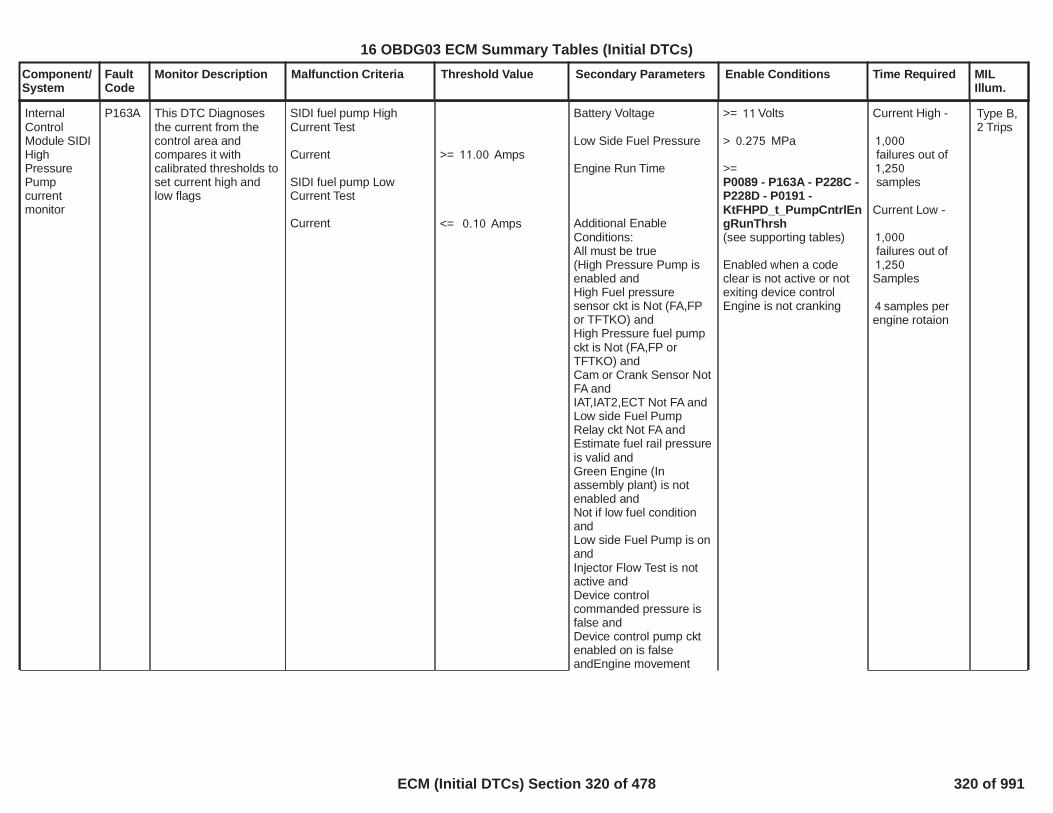
Component/System
FaultCode
Monitor Description Malfunction Criteria Threshold Value Secondary Parameters Enable Conditions Time Required MILIllum.
InternalControlModule SIDIHighPressurePumpcurrentmonitor
P163A This DTC Diagnosesthe current from thecontrol area andcompares it withcalibrated thresholds toset current high andlow flags
SIDI fuel pump HighCurrent Test
Current
SIDI fuel pump LowCurrent Test
Current
>= Amps11.00
<= Amps0.10
Battery Voltage
Low Side Fuel Pressure
Engine Run Time
Additional EnableConditions:All must be true(High Pressure Pump isenabled andHigh Fuel pressuresensor ckt is Not (FA,FPor TFTKO) andHigh Pressure fuel pumpckt is Not (FA,FP orTFTKO) andCam or Crank Sensor NotFA andIAT,IAT2,ECT Not FA andLow side Fuel PumpRelay ckt Not FA andEstimate fuel rail pressureis valid andGreen Engine (Inassembly plant) is notenabled andNot if low fuel conditionandLow side Fuel Pump is onandInjector Flow Test is notactive andDevice controlcommanded pressure isfalse andDevice control pump cktenabled on is falseandEngine movement
>= Volts11
> MPa0.275
>=P0089 - P163A - P228C -P228D - P0191 -KtFHPD_t_PumpCntrlEngRunThrsh(see supporting tables)
Enabled when a codeclear is not active or notexiting device controlEngine is not cranking
Current High -
1,000failures out of1,250samples
Current Low -
1,000failures out of1,250Samples
samples per4engine rotaion
Type B,2 Trips
322
16 OBDG03 ECM Summary Tables (Initial DTCs)
ECM (Initial DTCs) Section 320 of 478 320 of 991

Component/System
FaultCode
Monitor Description Malfunction Criteria Threshold Value Secondary Parameters Enable Conditions Time Required MILIllum.
detected is true andManufacturers enablecounter is 0)Flex Fuel Sensor Not FAIgnition voltage out ofcorrelation error(P1682)not active and
Barometric PressureInlet Air TempFuel Temp
>= KPA70.0>= degC-10.0
<= Temp degC <=-10126
323
16 OBDG03 ECM Summary Tables (Initial DTCs)
ECM (Initial DTCs) Section 321 of 478 321 of 991

Component/System
FaultCode
Monitor Description Malfunction Criteria Threshold Value Secondary Parameters Enable Conditions Time Required MILIllum.
IgnitionVoltageCorrelation
P1682 Detect a continuous orintermittent out ofcorrelation between theRun/Crank IgnitionVoltage & thePowertrain RelayIgnition Voltage
|Run/Crank – PT RelayIgnition| >
Volts3.00 Powertrain commandedon
AND
(Run/Crank voltage >Table, f(IAT). Seesupporting tables:P1682_PT Relay Pull-inRun/Crank Voltage f(IAT)
OR PT Relay Ignitionvoltage > )5.50
AND
Run/Crank voltage >.5.50
/240 480counts or0.175sec continuous;12.5 ms/count inmain processor
Type A,1 Trips
324
16 OBDG03 ECM Summary Tables (Initial DTCs)
ECM (Initial DTCs) Section 322 of 478 322 of 991
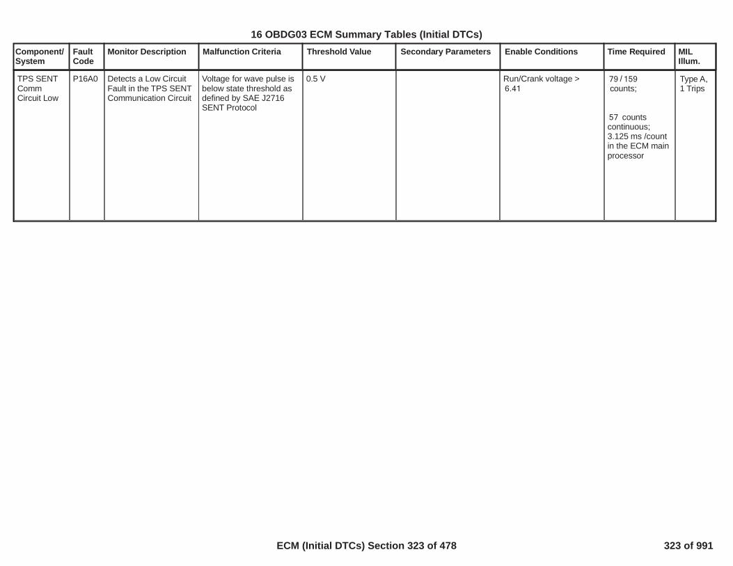
Component/System
FaultCode
Monitor Description Malfunction Criteria Threshold Value Secondary Parameters Enable Conditions Time Required MILIllum.
TPS SENTCommCircuit Low
P16A0 Detects a Low CircuitFault in the TPS SENTCommunication Circuit
Voltage for wave pulse isbelow state threshold asdefined by SAE J2716SENT Protocol
0.5 V Run/Crank voltage >6.41
/79 159counts;
counts57continuous;3.125 ms /countin the ECM mainprocessor
Type A,1 Trips
325
16 OBDG03 ECM Summary Tables (Initial DTCs)
ECM (Initial DTCs) Section 323 of 478 323 of 991

Component/System
FaultCode
Monitor Description Malfunction Criteria Threshold Value Secondary Parameters Enable Conditions Time Required MILIllum.
TPS SENTCommCircuit High
P16A1 Detects a High CircuitFault in the TPS SENTCommunication Circuit
Voltage for wave pulse isabove state threshold asdefined by SAE J2716SENT Protocol
4.1 V Run/Crank voltage >6.41
/79 159counts;
counts57continuous;3.125 ms /countin the ECM mainprocessor
Type A,1 Trips
326
16 OBDG03 ECM Summary Tables (Initial DTCs)
ECM (Initial DTCs) Section 324 of 478 324 of 991

Component/System
FaultCode
Monitor Description Malfunction Criteria Threshold Value Secondary Parameters Enable Conditions Time Required MILIllum.
TPS SENTCommCircuitPerformance
P16A2 Detects a MessageFault in the TPS SENTCommunication Circuit Message Pulse <
Message Pulse >orMessage Age Limit >=
orSignal CRC fails
ms0.125977ms0.209991
ms3.125
Run/Crank voltage >6.41
/79 159counts;
counts57continuous;3.125 ms /countin the ECM mainprocessor
Type A,1 Trips
327
16 OBDG03 ECM Summary Tables (Initial DTCs)
ECM (Initial DTCs) Section 325 of 478 325 of 991

Component/System
FaultCode
Monitor Description Malfunction Criteria Threshold Value Secondary Parameters Enable Conditions Time Required MILIllum.
IgnitionVoltageCorrelation#2
P16A7 Detect a continuous orintermittent out ofcorrelation between theRun/Crank IgnitionVoltage & thePowertrain RelayIgnition Voltage #2
|Run/Crank – PT RelayIgnition| >
Volts3.00 Powertrain commandedon
AND
(Run/Crank voltage >Table, f(IAT). Seesupporting tables:P1682_PT Relay Pull-inRun/Crank Voltage f(IAT)
OR PT Relay Ignitionvoltage > )5.50
AND
Run/Crank voltage >.5.50
/240 480counts or0.175sec continuous;12.5 ms/count inmain processor
Type A,1 Trips
328
16 OBDG03 ECM Summary Tables (Initial DTCs)
ECM (Initial DTCs) Section 326 of 478 326 of 991

Component/System
FaultCode
Monitor Description Malfunction Criteria Threshold Value Secondary Parameters Enable Conditions Time Required MILIllum.
EngineControlsIgnitionRelayFeedbackCircuit 2 LowVoltage -(GEN IIIControllersONLY)
P16AF Diagnoses ignitionfeedback circuit 2 lowvoltage
Engine controls ignitionrelay feedback circuit 2low voltage
Relay voltage <= 5.00 Powertrain relay low diagenable
Powertrain relay voltage
Run Crank voltage
Powertrain relay state
= 1.00
>= 11.00
> 9.00
= ON
failures out5.00of samples6.00
1000 ms /sample
Type C,No SVS
329
16 OBDG03 ECM Summary Tables (Initial DTCs)
ECM (Initial DTCs) Section 327 of 478 327 of 991

Component/System
FaultCode
Monitor Description Malfunction Criteria Threshold Value Secondary Parameters Enable Conditions Time Required MILIllum.
EngineControlsIgnitionRelayFeedbackCircuit 2High Voltage- (GEN IIIControllersONLY)
P16B3 Diagnoses ignitionfeedback circuit 2 highvoltage
Engine controls ignitionrelay feedback circuit 2high voltage
Relay voltage >= 4.00 Powertrain relay high diagenable
Powertrain relay state
= 1.00
= INACTIVE
failures50.00out of 63.00samples
100 ms / sample
Type B,2 Trips
330
16 OBDG03 ECM Summary Tables (Initial DTCs)
ECM (Initial DTCs) Section 328 of 478 328 of 991

Component/System
FaultCode
Monitor Description Malfunction Criteria Threshold Value Secondary Parameters Enable Conditions Time Required MILIllum.
BatteryMonitorModuleCircuit LowVoltage
P16D4 This DTC monitors fora battery module lowvoltage circuit fault
Battery Module signals alow voltage circuit fault viaLIN bus
VeVITR_U_12VBattVolt < 3.00 Volts
for 200 fail counts outof 250 sample counts
The diagnostic is enabled
System DiagnosticsDisabled
Power Mode
12V System ReferenceVoltage
LIN Bus Off or BatteryModule CommunicationFaults Active
Outside Air Temperature
Outside Air TemperatureValidity Bit
= (1 indicates enabled)1
= False
Not equal off
> Volts9.00and< Volts99.00
= False
> Celsius-20.00and< Celsius50.00= True
Diagnostic runsin the 250 msloop
Type B,2 Trips
331
16 OBDG03 ECM Summary Tables (Initial DTCs)
ECM (Initial DTCs) Section 329 of 478 329 of 991

Component/System
FaultCode
Monitor Description Malfunction Criteria Threshold Value Secondary Parameters Enable Conditions Time Required MILIllum.
BatteryMonitorModuleCircuit HighVoltage
P16D5 This DTC monitors fora battery module highvoltage circuit fault
Battery Module signals ahigh voltage circuit faultvia LIN bus
VeVITR_U_12VBattVolt > 26.00 Voltsfor 200 fail counts outof 250 sample counts
The diagnostic is enabled
System DiagnosticsDisabled
Power Mode
12V System ReferenceVoltage
LIN Bus Off or BatteryModule CommunicationFaults Active
Outside Air Temperature
Outside Air TemperatureValidity Bit
= (1 indicates enabled)1
= False
Not equal off
> Volts9.00and< Volts99.00
= False
> Celsius-20.00and< Celsius50.00
= True
Diagnostic runsin the 250 msloop
Type B,2 Trips
332
16 OBDG03 ECM Summary Tables (Initial DTCs)
ECM (Initial DTCs) Section 330 of 478 330 of 991

Component/System
FaultCode
Monitor Description Malfunction Criteria Threshold Value Secondary Parameters Enable Conditions Time Required MILIllum.
BatteryMonitorModuleCurrent Low
P16D6 This DTC monitors fora battery modulecurrent low fault
Battery Module signals acurrent low fault via LINbus
VeVITR_I_12VBattCurrRaw
< -1400 Ampsfor 200 fail counts outof 250 sample counts
The diagnostic is enabled
System DiagnosticsDisabled
Power Mode
12V System ReferenceVoltage
LIN Bus Off or BatteryModule CommunicationFaults Active
Outside Air Temperature
Outside Air TemperatureValidity Bit
= (1 indicates enabled)1
= False
Not equal off
> Volts9.00and< Volts99.00
= False
> Celsius-20.00and< Celsius50.00
= True
Diagnostic runsin the 250 msloop
Type B,2 Trips
333
16 OBDG03 ECM Summary Tables (Initial DTCs)
ECM (Initial DTCs) Section 331 of 478 331 of 991

Component/System
FaultCode
Monitor Description Malfunction Criteria Threshold Value Secondary Parameters Enable Conditions Time Required MILIllum.
BatteryModuleMonitorTimerPerformance
P16DC This DTC monitors fora battery module timerperformance fault
Battery Module timer isinactive for
Case 1: Wake Up Test
A: LIN Bus Off Timer /seconds1,800.00
or
B: (LIN Bus Off Timer +seconds) /1,800.00seconds1,800.00
or
C: (LIN Bus Off Timer -seconds) /1,800.00seconds1,800.00
Case 2: Sequential Test
Sequential Test is enabled
If the calculatedwakeup value issmaller than 24.00counts, then thesmaller value will beoutputed. If thecalculated wakeupvalue is greater than
counts, then the24.00calibration itself isoutputed.
If any outputs aboveare not not equal to theIBS maximum downcounter counts, thediagnostic fails.
This portion of thediagnostic is not used.
= (1 indicates0enabled)
The diagnostic is enabled
System DiagnosticsDisabled
Power Mode
12V System ReferenceVoltage
LIN Bus Off or BatteryModule CommunicationFaults Active
Outside Air Temperature
Outside Air TemperatureValidity Bit
Historical TemperatureData Trigger Request
Module Off Timer FaultActive
Run Crank Low TimerError
Code Clear Request
IBS Measure TemperaureData Available
TPTKO OR TFTKO
= (1 indicates enabled)1
= False
Not equal off
> Volts9.00and< Volts99.00
= False
> Celsius-20.00and< Celsius50.00
= True
= 1 (initializes to 0 thentransitions to 1 once datais available- NEED TOSEE POSITIVE RISINGEDGE)
= False
= False
= False (latched when setTrue)
= True
= False(when
Diagnostic runsin the 250 msloop
Type B,2 Trips
334
16 OBDG03 ECM Summary Tables (Initial DTCs)
ECM (Initial DTCs) Section 332 of 478 332 of 991

Component/System
FaultCode
Monitor Description Malfunction Criteria Threshold Value Secondary Parameters Enable Conditions Time Required MILIllum.
IBS Down Counter Value
Spurious Reset
KeVITD_b_TimerPerf_DFIRDisable = 0)Calibration is set to 0
Not equal to 25.00
= False
335
16 OBDG03 ECM Summary Tables (Initial DTCs)
ECM (Initial DTCs) Section 333 of 478 333 of 991

Component/System
FaultCode
Monitor Description Malfunction Criteria Threshold Value Secondary Parameters Enable Conditions Time Required MILIllum.
BatteryMonitorModuleCurrent High
P16DD This DTC monitors fora battery modulecurrent high fault
Battery Module signals acurrent high fault via LINbus
VeVITR_I_12VBattCurrRaw
> +1400 Ampsfor 200 fail counts outof 250 sample counts
The diagnostic is enabled
System DiagnosticsDisabled
Power Mode
12V System ReferenceVoltage
LIN Bus Off or BatteryModule CommunicationFaults Active
Outside Air Temperature
Outside Air TemperatureValidity Bit
= (1 indicates enabled)1
= False
Not equal off
> Volts9.00and< Volts99.00
= False
> Celsius-20.00and< Celsius50.00
= True
Diagnostic runsin the 250 msloop
Type B,2 Trips
336
16 OBDG03 ECM Summary Tables (Initial DTCs)
ECM (Initial DTCs) Section 334 of 478 334 of 991

Component/System
FaultCode
Monitor Description Malfunction Criteria Threshold Value Secondary Parameters Enable Conditions Time Required MILIllum.
BatteryMonitorInternalTemperatureCircuit Low
P16DE This DTC monitors fora battery moduleinternal temperaturecircuit low fault
Battery Module rawtemperature 1 value > Celsius120.00
The historical modediagnostic is enabledand / orThe continuous modediagnostic is enabled
System DiagnosticsDisabled
Power Mode
12V System ReferenceVoltage
LIN Bus Off or BatteryModule CommunicationFaults Active
Outside Air Temperature
Outside Air TemperatureValidity Bit
For Historical ModeIBS Down Counter (overLIN bus)For Continuous ModeIBS Down Counter (overLIN bus)
IBS Measure TemperatureData Available over LINbus
= (1 indicates enabled)1
= (1 indicates enabled)1
= False
Not equal off
> Volts9.00and< Volts99.00
= False
> Celsius-20.00and< Celsius50.00
= True
Between 1 and 24 or zero
= zero
= True
failed samples4within total5samples
Diagnostic runsin the 250 msloop
Type B,2 Trips
337
16 OBDG03 ECM Summary Tables (Initial DTCs)
ECM (Initial DTCs) Section 335 of 478 335 of 991

Component/System
FaultCode
Monitor Description Malfunction Criteria Threshold Value Secondary Parameters Enable Conditions Time Required MILIllum.
BatteryMonitorInternalTemperatureCircuit High
P16DF This DTC monitors fora battery moduleinternal temperaturecircuit high fault
Battery Module rawtemperature 1 value < Celsius-43.00
The historical modediagnostic is enabledand / orThe continuous modediagnostic is enabled
System DiagnosticsDisabled
Power Mode
12V System ReferenceVoltage
LIN Bus Off or BatteryModule CommunicationFaults Active
Outside Air Temperature
Outside Air TemperatureValidity Bit
For Historical ModeIBS Down Counter (overLIN bus)For Continuous ModeIBS Down Counter (overLIN bus)
IBS Measure TemperatureData Available over LINbus
= (1 indicates enabled)1
= (1 indicates enabled)1
= False
Not equal off
> Volts9.00and< Volts99.00
= False
> Celsius-20.00and< Celsius50.00
= True
Between 1 and 24
= zero
= True
failed samples4within total5samples
Diagnostic runsin the 250 msloop
Type B,2 Trips
338
16 OBDG03 ECM Summary Tables (Initial DTCs)
ECM (Initial DTCs) Section 336 of 478 336 of 991

Component/System
FaultCode
Monitor Description Malfunction Criteria Threshold Value Secondary Parameters Enable Conditions Time Required MILIllum.
BatteryMonitorModuleRandomAccessMemory(RAM) Error
P16E1 This DTC monitors fora battery module RAMmemory fault
Battery Module signals aRAM memory fault via LINbus
VeVITR_e_IBS_IntRAM_Fault
=CeVITR_e_DiagFailed
The diagnostic is enabled
System DiagnosticsDisabled
Power Mode
12V System ReferenceVoltage
LIN Bus Off or BatteryModule CommunicationFaults Active
Outside Air Temperature
Outside Air TemperatureValidity Bit
= (1 indicates enabled)1
= False
Not equal off
> Volts9.00and< Volts99.00
= False
> Celsius-20.00and< Celsius50.00
= True
Diagnostic runsin the 250 msloop
Type B,2 Trips
339
16 OBDG03 ECM Summary Tables (Initial DTCs)
ECM (Initial DTCs) Section 337 of 478 337 of 991

Component/System
FaultCode
Monitor Description Malfunction Criteria Threshold Value Secondary Parameters Enable Conditions Time Required MILIllum.
BatteryMonitorModuleRead OnlyMemory(ROM) Error
P16E2 This DTC monitors fora battery module ROMmemory fault
Battery Module signals aROM memory fault viaLIN bus
VeVITR_e_IBS_IntROM_Fault
=CeVITR_e_DiagFailed
The diagnostic is enabled
System DiagnosticsDisabled
Power Mode
12V System ReferenceVoltage
LIN Bus Off or BatteryModule CommunicationFaults Active
Outside Air Temperature
Outside Air TemperatureValidity Bit
= (1 indicates enabled)1
= False
Not equal off
> Volts9.00and< Volts99.00
= False
> Celsius-20.00and< Celsius50.00
= True
Diagnostic runsin the 250 msloop
Type B,2 Trips
340
16 OBDG03 ECM Summary Tables (Initial DTCs)
ECM (Initial DTCs) Section 338 of 478 338 of 991

Component/System
FaultCode
Monitor Description Malfunction Criteria Threshold Value Secondary Parameters Enable Conditions Time Required MILIllum.
BatteryMonitorModule DataIncompatible
P16E3 This DTC monitors fora battery module dataincompatible fault
Battery Module datareceived over LIN busis incompatible.(Measured by any of thefollowing)
Historical Test
Absolute value of IBSbattery capacity C20 data(IBS Return Nominal C20- Ah)90.00
or
IBS Returns a batterytype that is not equal to
or
Absolute value of(IBS Return BatteryCalibration#1 U40@25 C- V)12.11
or
Absolute value of(IBS Return BatteryCalibration#1 U80@25 C- V)12.65
Continuous Test
Upon IBS wakeup, ifany of the belowHistorical Testconditions aresatisfied, thediagnostic fails.
> Ah5.00
CeBSER_e_IBS_CfgBatAGM
> Volts0.50
> Volts0.50
If any of the belowconditions are satisfiedfor fail counts out8.00
The historical modediagnostic is enabledand / orThe continuous modediagnostic is enabled
System DiagnosticsDisabled
Power Mode
12V System ReferenceVoltage
LIN Bus Off or BatteryModule CommunicationFaults Active
Outside Air Temperature
Outside Air TemperatureValidity Bit
Host Controller MECCounter
IBS Configuration DataAvailable over LIN bus
= (1 indicates enabled)1
= (1 indicates enabled)1
= False
Not equal off
> Volts9.00and< Volts99.00
= False
> Celsius-20.00and< Celsius50.00= True
<= 0
= True
Diagnostic runsin the 250 msloop
Type B,2 Trips
341
16 OBDG03 ECM Summary Tables (Initial DTCs)
ECM (Initial DTCs) Section 339 of 478 339 of 991

Component/System
FaultCode
Monitor Description Malfunction Criteria Threshold Value Secondary Parameters Enable Conditions Time Required MILIllum.
Absolute value of IBSbattery capacity C20 data(IBS Return Nominal C20- Ah)90.00
or
IBS Returns a batterytype that is not equal to
or
Absolute value of(IBS Return BatteryCalibration#1 U40@25 C- V)12.11
or
Absolute value of(IBS Return BatteryCalibration#1 U80@25 C- V)12.65
of sample10.00counts, the diagnosticfails.
> Ah5.00
CeBSER_e_IBS_CfgBatAGM
> Volts0.50
> Volts0.50
342
16 OBDG03 ECM Summary Tables (Initial DTCs)
ECM (Initial DTCs) Section 340 of 478 340 of 991

Component/System
FaultCode
Monitor Description Malfunction Criteria Threshold Value Secondary Parameters Enable Conditions Time Required MILIllum.
Equivance Ratio torquecompensation exceedsthreshold
-107.91Nm
Ignition State Accessory, run or crank Up/down timer475ms continuous,0.5down timemultipier
InternalControlModuleRedundantMemoryPerformance
P16F3 Detect ProcessorCalculation faults dueto RAM corruptions,ALU failures and ROMfailures
For all of the followingcases: If the individualdiagnostic threshold isequal to 2048 ms, thisindividual case is notapplicable. If any ofthe following cases areX out of Y diagnosticsand the fail (x) isgreater than thesample (Y), thisindividual case is alsonot applicable.
Type A,1 Trips
Absolute differencebetween Equivance Ratiotorque compensation andits dual store out ofbounds given by threshold
107.91Nm
Ignition State Accessory, run or crank Up/down timer175ms continuous,0.5down timemultipier
Absolute difference ofAccessory torque and itsredundant calculation isout of bounds given bythreshold range
107.91Nm
Ignition State Accessory, run or crank Up/down timer175ms continuous,0.5down timemultipier
16 OBDG03 ECM Summary Tables (Initial DTCs)
ECM (Initial DTCs) Section 341 of 478 341 of 991

Component/System
FaultCode
Monitor Description Malfunction Criteria Threshold Value Secondary Parameters Enable Conditions Time Required MILIllum.
Absolute difference ofFiltered Air-per-cylinderand its redundantcalculation is out ofbounds given by thresholdrange
217.41mg
Ignition State Accessory, run or crank Up/down timer175ms continuous,0.5down timemultipier
Absolute differencebetween the previousFinal Advance and thecurrent Final Advance notAdjusted for EquivalenceRatio is out of boundsgiven by threshold range
22.52degrees
Engine speed >0rpm Up/down timer140ms continuous,0.5down timemultipier
Torque Learn offset is outof bounds given bythreshold range
High Threshold
0.00Nm
Low Threshold
0.00
Ignition State Accessory, run or crank Up/down timer175ms continuous,0.5down timemultipier
16 OBDG03 ECM Summary Tables (Initial DTCs)
ECM (Initial DTCs) Section 342 of 478 342 of 991

Component/System
FaultCode
Monitor Description Malfunction Criteria Threshold Value Secondary Parameters Enable Conditions Time Required MILIllum.
Nm
One step aheadcalculation of air-per-cylinder and two stepahead is greater thanthreshold
80.00mg
Engine speed >650rpm
Up/down timer440ms continuous,0.5down timemultipier
Difference betweenUnmanaged Spark andPACS Spark is greaterthan threshold
22.52degrees
Ignition State Accessory, run or crank Up/down timer475ms continuous,0.5down timemultipier
Commanded PredictedEngine Torque and itsdual store do not match
N/A Ignition State Accessory, run or crank Up/down timer2,048ms continuous,0.5down timemultipier
16 OBDG03 ECM Summary Tables (Initial DTCs)
ECM (Initial DTCs) Section 343 of 478 343 of 991

Component/System
FaultCode
Monitor Description Malfunction Criteria Threshold Value Secondary Parameters Enable Conditions Time Required MILIllum.
Zero pedal axle torque isout of bounds given bythreshold range
High Threshold
1,429.54NmLow Threshold
-65,535.00Nm
Ignition State Accessory, run or crank Up/down timer175ms continuous,0.5down timemultipier
Creep Coast Axle Torqueis out of bounds given bythreshold range
High Threshold
1,429.54NmLow Threshold
-65,535.00Nm
Ignition State Accessory, run or crank Up/down timer2,048ms continuous,0.5down timemultipier
Absolute difference ofFriction torque and itsredundant calculation isout of bounds given bythreshold range
107.91Nm
Ignition State Accessory, run or crank Up/down timer175ms continuous,0.5down timemultipier
16 OBDG03 ECM Summary Tables (Initial DTCs)
ECM (Initial DTCs) Section 344 of 478 344 of 991

Component/System
FaultCode
Monitor Description Malfunction Criteria Threshold Value Secondary Parameters Enable Conditions Time Required MILIllum.
Arbitrated Air-Per-Cylinderfilter coefficient is out ofbounds given by thresholdrange
High Threshold
1.000
Low Threshold
0.074
Ignition State Accessory, run or crank Up/down timer475ms continuous,0.5down timemultipier
Launch spark is active butthe launch sparkredundant path indicatesit should not be active
N/A Engine speed <7,000.00or7,200.00rpm (hysteresis pair)
Up/down timer140ms continuous,0.5down timemultipier
Rate limited vehicle speedand its dual store do notequal
N/A Time since first CANmessage with vehiclespeed >=0.500sec
/10 20counts;25.0msec/count
16 OBDG03 ECM Summary Tables (Initial DTCs)
ECM (Initial DTCs) Section 345 of 478 345 of 991

Component/System
FaultCode
Monitor Description Malfunction Criteria Threshold Value Secondary Parameters Enable Conditions Time Required MILIllum.
Commanded enginetorque due to fastactuators and its dualstore do not equal
N/A Ignition State Accessory, run or crank Up/down timer475ms continuous,0.5down timemultipier
Commanded enginetorque due to slowactuators and its dualstore do not equal
N/A Ignition State Accessory, run or crank Up/down timer475ms continuous,0.5down timemultipier
TOS to wheel speedconversion factor is out ofbounds given by thresholdrange
High Threshold:
1.10T/C Range Hi
0.10T/C Range Lo
Low Threshold:
1.10T/C Range Hi
0.10T/C Range Lo
Ignition State Accessory, run or crank /255 6counts;25.0msec/count
16 OBDG03 ECM Summary Tables (Initial DTCs)
ECM (Initial DTCs) Section 346 of 478 346 of 991

Component/System
FaultCode
Monitor Description Malfunction Criteria Threshold Value Secondary Parameters Enable Conditions Time Required MILIllum.
Cylinders active greaterthan commanded
2cylinders
Engine run flag = TRUE >2.00sNumber of cylinder eventssince engine run >24
No fuel injector faultsactive
Up/down timer140ms continuous,0.5down timemultipier
Transfer case neutralrequest from four wheeldrive logic does not matchwith operating conditions
N/A Ignition State Accessory, run or crank
Transfer case range validand not over-ridden
FWD Apps only
/32 400counts;
25.0msec/count
Driver progression modeand its dual store do notequal
N/A Ignition State Accessory, run or crank Up/down timer475ms continuous,0.5down time
16 OBDG03 ECM Summary Tables (Initial DTCs)
ECM (Initial DTCs) Section 347 of 478 347 of 991

Component/System
FaultCode
Monitor Description Malfunction Criteria Threshold Value Secondary Parameters Enable Conditions Time Required MILIllum.
multipier
Predicted torque foruncorrected zero pedaldetermination is greaterthan calculated limit.
Table, f(Engine, OilTemp).P16F3_Speed ControlExternal Load f(OilTemp, RPM)+107.91Nm
Ignition State Accessory, run or crank Up/down timer175ms continuous,0.5down timemultipier
Engine Predicted RequestWithout Motor is greaterthan its redundantcalculation plus threshold
106.91Nm
Ignition State Accessory, run or crank Up/down timer175ms continuous,0.5down timemultipier
Engine ImmediateRequest Without Motor isgreater than its redundantcalculation plus threshold
106.91Nm
Ignition State Accessory, run or crank Up/down timer175ms continuous,0.5
16 OBDG03 ECM Summary Tables (Initial DTCs)
ECM (Initial DTCs) Section 348 of 478 348 of 991

Component/System
FaultCode
Monitor Description Malfunction Criteria Threshold Value Secondary Parameters Enable Conditions Time Required MILIllum.
down timemultipier
Positive Torque Offset isgreater than its redundantcalculation plus threshold
OR
Positive Torque Offset isless than its redundantcalculation minusthreshold
107.91Nm
Ignition State Accessory, run or crank Up/down timer175ms continuous,0.5down timemultipier
Commanded PredictedEngine Request is greaterthan its redundantcalculation plus threshold
107.91Nm
Ignition State Accessory, run or crank Up/down timer475ms continuous,
down time
16 OBDG03 ECM Summary Tables (Initial DTCs)
ECM (Initial DTCs) Section 349 of 478 349 of 991

Component/System
FaultCode
Monitor Description Malfunction Criteria Threshold Value Secondary Parameters Enable Conditions Time Required MILIllum.
multipier 0.5
Commanded HybridPredicted CrankshaftRequest is greater than itsredundant calculation plusthreshold
4,096.00Nm
Ignition State Accessory, run or crank Up/down timer2,048ms continuous,0.5down timemultipier
Commanded HybridImmediate CrankshaftRequest is less than itsredundant calculationminus threshold
4,096.00Nm
Ignition State Accessory, run or crank Up/down timer2,048ms continuous,0.5down timemultipier
16 OBDG03 ECM Summary Tables (Initial DTCs)
ECM (Initial DTCs) Section 350 of 478 350 of 991

Component/System
FaultCode
Monitor Description Malfunction Criteria Threshold Value Secondary Parameters Enable Conditions Time Required MILIllum.
Regeneration BrakeAssist is not within aspecified range
Brake Regen Assist <0 Nm orBrake Regen Assist >0.00Nm
Ignition State Accessory, run or crank Up/down timer2,048ms continuous,0.5down timemultipier
Cylinder Spark DeltaCorrection exceeds theabsolute difference ascompared to UnadjustedCylinder Spark Delta
22.52degrees
Ignition State Accessory, run or crank Up/down timer175ms continuous,0.5down timemultipier
1. Cylinder Torque Offsetexceeds step sizethreshold
OR
1.107.91Nm
Ignition State Accessory, run or crank Up/down timer175ms continuous,0.5down timemultipier
16 OBDG03 ECM Summary Tables (Initial DTCs)
ECM (Initial DTCs) Section 351 of 478 351 of 991
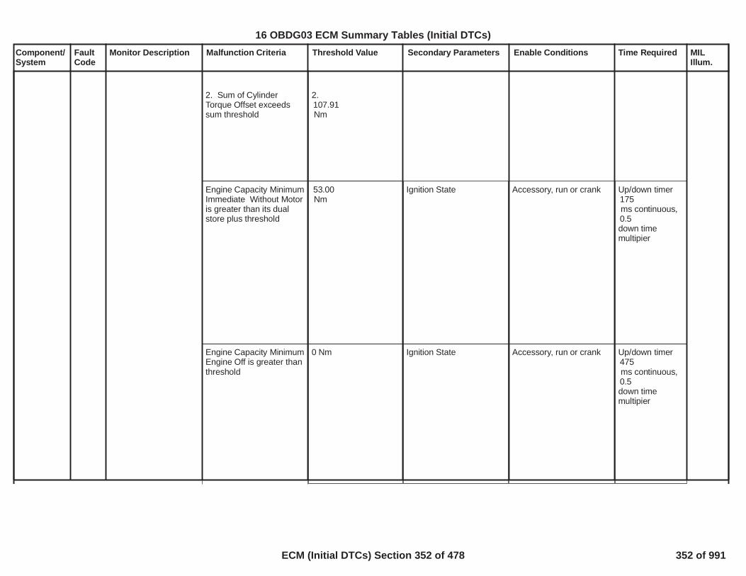
Component/System
FaultCode
Monitor Description Malfunction Criteria Threshold Value Secondary Parameters Enable Conditions Time Required MILIllum.
2. Sum of CylinderTorque Offset exceedssum threshold
2.107.91Nm
Engine Capacity MinimumImmediate Without Motoris greater than its dualstore plus threshold
53.00Nm
Ignition State Accessory, run or crank Up/down timer175ms continuous,0.5down timemultipier
Engine Capacity MinimumEngine Off is greater thanthreshold
0 Nm Ignition State Accessory, run or crank Up/down timer475ms continuous,0.5down timemultipier
16 OBDG03 ECM Summary Tables (Initial DTCs)
ECM (Initial DTCs) Section 352 of 478 352 of 991

Component/System
FaultCode
Monitor Description Malfunction Criteria Threshold Value Secondary Parameters Enable Conditions Time Required MILIllum.
Engine Capacity MinimumEngine ImmediateWithout Motor is greaterthan threshold
0 Nm Ignition State Accessory, run or crank Up/down timer2,048ms continuous,0.5down timemultipier
Commanded ImmediateEngine Request is greaterthan its redundantcalculation plus threshold
107.91Nm
Ignition State Accessory, run or crank Up/down timer2,048ms continuous,0.5down timemultipier
Engine Speed LoresIntake Firing (eventbased) calculation doesnot equal its redundantcalculation
N/A Engine speed greaterthan 0rpm
Up/down timer140ms continuous,0.5down timemultipier
16 OBDG03 ECM Summary Tables (Initial DTCs)
ECM (Initial DTCs) Section 353 of 478 353 of 991

Component/System
FaultCode
Monitor Description Malfunction Criteria Threshold Value Secondary Parameters Enable Conditions Time Required MILIllum.
Engine Speed LoresIntake Firing timing (eventbased) calculation doesnot equal its redundantcalculation
N/A Engine speed greaterthan 0rpm
Up/down timer140ms continuous,0.5down timemultipier
Idle speed controlcalculated predictedminimum torque requestexceeds calculated torquelimit
Table, f(Oil Temp,RPM). See supportingtables:P16F3_Speed ControlExternal Load f(OilTemp, RPM)+107.91Nm
Ignition State Accessory, run or crank Up/down timer175ms continuous,0.5down timemultipier
Idle speed controlcalculated predictedminimum torque withoutreserves exceedscalculated torque limit
Table, f(Oil Temp,RPM). See supportingtables:P16F3_Speed ControlExternal Load f(OilTemp, RPM)+
Ignition State Accessory, run or crank Up/down timer175ms continuous,0.5down timemultipier
16 OBDG03 ECM Summary Tables (Initial DTCs)
ECM (Initial DTCs) Section 354 of 478 354 of 991

Component/System
FaultCode
Monitor Description Malfunction Criteria Threshold Value Secondary Parameters Enable Conditions Time Required MILIllum.
107.91Nm
Difference between DriverRequested ImmediateTorque primary path andits secondary exceedsthreshold
1,429.54Nm
Ignition State Accessory, run or crank Up/down timer2,048ms continuous,0.5down timemultipier
Driver Immediate Requestis less than its redundantcalculation minusthreshold
1,429.54Nm
Ignition State Accessory, run or crank Up/down timer475ms continuous,0.5down timemultipier
Commanded ImmediateRequest is greater than itsredundant calculation plusthreshold
1,429.54Nm
Ignition State Accessory, run or crank Up/down timer2,048ms continuous,0.5down time
16 OBDG03 ECM Summary Tables (Initial DTCs)
ECM (Initial DTCs) Section 355 of 478 355 of 991

Component/System
FaultCode
Monitor Description Malfunction Criteria Threshold Value Secondary Parameters Enable Conditions Time Required MILIllum.
OR
Commanded ImmediateRequest is less than itsredundant calculationminus threshold
multipier
Commanded ImmediateResponse Type is set toInactive
N/A Ignition State Accessory, run or crank Up/down timer2,048ms continuous,0.5down timemultipier
Difference betweenCruise Axle TorqueArbitrated Request andCruise Axle TorqueRequest exceedsthreshold
178.69Nm
Cruise has been engagedfor more than4.00seconds
Up/down timer2,048ms continuous,0.5down timemultipier
16 OBDG03 ECM Summary Tables (Initial DTCs)
ECM (Initial DTCs) Section 356 of 478 356 of 991
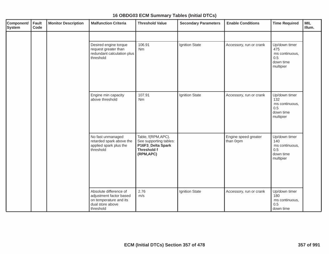
Component/System
FaultCode
Monitor Description Malfunction Criteria Threshold Value Secondary Parameters Enable Conditions Time Required MILIllum.
Desired engine torquerequest greater thanredundant calculation plusthreshold
106.91Nm
Ignition State Accessory, run or crank Up/down timer475ms continuous,0.5down timemultipier
Engine min capacityabove threshold
107.91Nm
Ignition State Accessory, run or crank Up/down timer132ms continuous,0.5down timemultipier
No fast unmanagedretarded spark above theapplied spark plus thethreshold
Table, f(RPM,APC).See supporting tables:P16F3_Delta SparkThreshold f(RPM,APC)
Engine speed greaterthan 0rpm
Up/down timer140ms continuous,0.5down timemultipier
Absolute difference ofadjustment factor basedon temperature and itsdual store abovethreshold
2.76m/s
Ignition State Accessory, run or crank Up/down timer180ms continuous,0.5down time
16 OBDG03 ECM Summary Tables (Initial DTCs)
ECM (Initial DTCs) Section 357 of 478 357 of 991

Component/System
FaultCode
Monitor Description Malfunction Criteria Threshold Value Secondary Parameters Enable Conditions Time Required MILIllum.
multipier
1. Absolute difference ofredundant calculatedengine speed abovethreshold
2,139RPM
Engine speed greaterthan 0 RPM
Up/down timer140ms continuous,0.5down timemultipier
After throttle bladepressure and its dualstore do not match
N/A Ignition State Accessory, run or crank Up/down timer175ms continuous,0.5down timemultipier
Speed Control'sPreditcted TorqueRequest and its dual storedo not match
N/A Ignition State Accessory, run or crank Up/down timer175ms continuous,0.5down timemultipier
16 OBDG03 ECM Summary Tables (Initial DTCs)
ECM (Initial DTCs) Section 358 of 478 358 of 991

Component/System
FaultCode
Monitor Description Malfunction Criteria Threshold Value Secondary Parameters Enable Conditions Time Required MILIllum.
Engine oil temperatureand its dual store do notmatch
N/A Ignition State Accessory, run or crank Up/down timer420ms continuous,0.5down timemultipier
Desired throttle positiongreater than redundantcalculation plus threshold
10.00percent
Ignition State Accessory, run or crank Up/down timer175ms continuous,0.5down timemultipier
Absolute difference of therate limited pre-throttlepressure and itsredundant calculationgreater than threshold
0.06kpa
Ignition State Accessory, run or crank Up/down timer175ms continuous,0.5down timemultipier
Throttle desired torqueabove desired torque plusthreshold
107.91Nm
Ignition State Accessory, run or crank Up/down timer475ms continuous,0.5down timemultipier
16 OBDG03 ECM Summary Tables (Initial DTCs)
ECM (Initial DTCs) Section 359 of 478 359 of 991

Component/System
FaultCode
Monitor Description Malfunction Criteria Threshold Value Secondary Parameters Enable Conditions Time Required MILIllum.
Desired filtered throttletorque exceeds thethreshold plus the higherof desired throttle torqueor modeled throttle torque
107.91Nm
Ignition State Accessory, run or crank Up/down timer475ms continuous,0.5down timemultipier
Torque feedbackproportional term is out ofallowable range or its dualstore copy does notmatch
High Threshold
53.95Nm
Low Threshold
-53.95Nm
Ignition State Accessory, run or crank Up/down timer475ms continuous,0.5down timemultipier
Torque feedback integralterm magnitude or rate of
High Threshold Ignition State Accessory, run or crank Up/down timer475
16 OBDG03 ECM Summary Tables (Initial DTCs)
ECM (Initial DTCs) Section 360 of 478 360 of 991

Component/System
FaultCode
Monitor Description Malfunction Criteria Threshold Value Secondary Parameters Enable Conditions Time Required MILIllum.
change is out of allowablerange or its dual storecopy do not match
101.16Nm
Low Threshold
-107.91Nm
Rate of changethreshold
6.74Nm/loop
ms continuous,0.5down timemultipier
Difference of Final Torquefeedback proportionalplus integral term and itsredundant calculation isout of bounds given bythreshold range
High Threshold
107.91Nm
Low Threshold
- 107.91Nm
Ignition State Accessory, run or crank Up/down timer475ms continuous,0.5down timemultipier
16 OBDG03 ECM Summary Tables (Initial DTCs)
ECM (Initial DTCs) Section 361 of 478 361 of 991

Component/System
FaultCode
Monitor Description Malfunction Criteria Threshold Value Secondary Parameters Enable Conditions Time Required MILIllum.
Difference of torquedesired throttle area andits redundant calculationis out of bounds given bythreshold range
High Threshold
%0.50
Low Threshold- %0.50
Ignition State Accessory, run or crank Up/down timer475ms continuous,0.5down timemultipier
Difference of torquemodel coefficients and itsredundant calculation isout of bounds given bythreshold range
High ThresholdLow0.0003074
Threshold - 0.0003074
Ignition State Accessory, run or crank Up/down timer175ms continuous,0.5down timemultipier
Difference of base frictiontorque and its redundantcalculation is out ofbounds given by thresholdrange
High Threshold
107.91Nm
Low Threshold
- 107.91Nm
Ignition State Accessory, run or crank Up/down timer475ms continuous,0.5down timemultipier
16 OBDG03 ECM Summary Tables (Initial DTCs)
ECM (Initial DTCs) Section 362 of 478 362 of 991

Component/System
FaultCode
Monitor Description Malfunction Criteria Threshold Value Secondary Parameters Enable Conditions Time Required MILIllum.
Accessory drive frictiontorque is out of boundsgiven by threshold range
High Threshold
107.91Nm
Low Threshold
0.00Nm
Ignition State Accessory, run or crank Up/down timer475ms continuous,0.5down timemultipier
AC friction torque isgreater than commandedby AC control software orless than threshold limit
High Threshold
39.00Nm
Low Threshold
0.00Nm
Ignition State Accessory, run or crank Up/down timer475ms continuous,0.5down timemultipier
Difference of Oiltemperature delta frictiontorque and its redundant
High Threshold
107.91
Ignition State Accessory, run or crank Up/down timer2,048ms continuous,
16 OBDG03 ECM Summary Tables (Initial DTCs)
ECM (Initial DTCs) Section 363 of 478 363 of 991

Component/System
FaultCode
Monitor Description Malfunction Criteria Threshold Value Secondary Parameters Enable Conditions Time Required MILIllum.
calculation is out ofbounds given by thresholdrange
Nm
Low Threshold
- 107.91Nm
0.5down timemultipier
Generator friction torqueis out of bounds given bythreshold range
High Threshold
107.91Nm
Low Threshold
0.00Nm
Ignition State Accessory, run or crank Up/down timer475ms continuous,0.5down timemultipier
Absolute differencebetween theSupercharger frictiontorque and its redundantcalculation greater thanthreshold
107.91Nm
Ignition State Accessory, run or crank Up/down timer475ms continuous,0.5down timemultipier
16 OBDG03 ECM Summary Tables (Initial DTCs)
ECM (Initial DTCs) Section 364 of 478 364 of 991

Component/System
FaultCode
Monitor Description Malfunction Criteria Threshold Value Secondary Parameters Enable Conditions Time Required MILIllum.
Filtered Torque errormagnitude or its increaserate of change is out ofallowable range or its dualstore copy do not match
High Threshold
107.91Nm
Low Threshold
-107.91Nm
Rate of changethreshold
6.74Nm/loop
Engine speed >0rpmMAF, MAP and BaroDTCs are false
Up/down timer475ms continuous,0.5down timemultipier
Torque errorcompensation is out ofbounds given by thresholdrange
High Threshold
107.91Nm
Low Threshold
0.00Nm
Ignition State Accessory, run or crank Up/down timer475ms continuous,0.5down timemultipier
16 OBDG03 ECM Summary Tables (Initial DTCs)
ECM (Initial DTCs) Section 365 of 478 365 of 991

Component/System
FaultCode
Monitor Description Malfunction Criteria Threshold Value Secondary Parameters Enable Conditions Time Required MILIllum.
Delta Torque Barocompensation is out ofbounds given by thresholdrange
High Threshold
4.25Nm
Low Threshold
-3.91Nm
Ignition State Accessory, run or crank Up/down timer175ms continuous,0.5down timemultipier
1. Difference of reservetorque value and itsredundant calculationexceed threshold
OR
2. Reserve request doesnot agree with operatingconditions or Difference offinal predicted torque andits redundant calculationexeed threshold
OR
3. Rate of change ofreserve torque exceedsthreshold, increasingdirection only
OR
4. Reserve engine torque
1. 106.91Nm
2. N/A
3. 106.91Nm
4. 106.91Nm
3. & 4.:Ignition State
1. & 2.:Torque reserve (conditionwhen spark controlgreater than optimum toallow fast transitions fortorque disturbances) >107.91Nm
3. & 4.:Accessory, run or crank
Up/down timer475ms continuous,0.5down timemultipier
16 OBDG03 ECM Summary Tables (Initial DTCs)
ECM (Initial DTCs) Section 366 of 478 366 of 991

Component/System
FaultCode
Monitor Description Malfunction Criteria Threshold Value Secondary Parameters Enable Conditions Time Required MILIllum.
above allowable capacitythreshold
Engine Vacuum and itsdual store do not match
N/A Ignition State Accessory, run or crank Up/down timer175ms continuous,0.5down timemultipier
Absolute difference of thecalculated Intake ManifoldPressure during engineevent versus during timeevent is greater thanthreshold
Table, f(DesiredEngine Torque). Seesupporting tables:P16F3_Delta MAPThreshold f(DesiredEngine Torque)
Engine speed >0rpm Up/down timer140ms continuous,0.5down timemultipier
Min. Axle Torque Capacityis greater than threshold
0.00Nm
Ignition State Accessory, run or crank Up/down timer175ms continuous,0.5down timemultipier
Driver Predicted Requestis greater than itsredundant calculation plusthreshold
1,429.54Nm
Ignition State Accessory, run or crank Up/down timer475ms continuous,0.5
16 OBDG03 ECM Summary Tables (Initial DTCs)
ECM (Initial DTCs) Section 367 of 478 367 of 991

Component/System
FaultCode
Monitor Description Malfunction Criteria Threshold Value Secondary Parameters Enable Conditions Time Required MILIllum.
OR
Driver Predicted Requestis less than its redundantcalculation minusthreshold
down timemultipier
Cold Delta Friction Torqueand its dual store do notmatch
N/A Ignition State Accessory, run or crank Up/down timer175ms continuous,0.5down timemultipier
Predicted torque for zeropedal determination isgreater than calculatedlimit.
Table, f(Oil Temp,RPM). See supportingtables: Speed ControlExternal Load f(OilTemp, RPM) +107.91Nm
Ignition State Accessory, run or crank Up/down timer175ms continuous,0.5down timemultipier
16 OBDG03 ECM Summary Tables (Initial DTCs)
ECM (Initial DTCs) Section 368 of 478 368 of 991

Component/System
FaultCode
Monitor Description Malfunction Criteria Threshold Value Secondary Parameters Enable Conditions Time Required MILIllum.
Commanded PredictedAxle Torque and its dualstore do not match
1 Nm Ignition State Accessory, run or crank Up/down timer475ms continuous,0.5down timemultipier
Steady State EstimatedEngine Torque and itsdual store are not equal
N/A AFM not changing fromActive to Inactive andpreload torque notchanging and one loopafter React command
Engine speed >0rpm
Up/down timer1,988ms continuous,0.5down timemultipier
Difference of Weightingfactor for number ofcylinders fueled and itsredundant calculation isabove threshold
0.26 Engine run flag = TRUE >10.00s
Up/down timer175ms continuous,0.5down timemultipier
Difference of minimumspark advance limit and
22.52degrees
Ignition State Accessory, run or crank Up/down timer140
16 OBDG03 ECM Summary Tables (Initial DTCs)
ECM (Initial DTCs) Section 369 of 478 369 of 991

Component/System
FaultCode
Monitor Description Malfunction Criteria Threshold Value Secondary Parameters Enable Conditions Time Required MILIllum.
its redundant calculationis out of bounds given bythreshold range
ms continuous,0.5down timemultipier
Difference of commandedspark advance andadjusted delivered is outof bounds given bythreshold range
22.52degrees
Engine speed >0rpm Up/down timer140ms continuous,0.5down timemultipier
Absolute differencebetween EstimatedEngine Torque and itsdual store are above athreshold
107.91Nm
Engine speed >0rpm Up/down timer475ms continuous,0.5down timemultipier
Absolute differencebetween EstimatedEngine Torque withoutreductions due to torquecontrol and its dual storeare above a threshold
107.91Nm
Engine speed >0rpm Up/down timer475ms continuous,0.5down timemultipier
16 OBDG03 ECM Summary Tables (Initial DTCs)
ECM (Initial DTCs) Section 370 of 478 370 of 991

Component/System
FaultCode
Monitor Description Malfunction Criteria Threshold Value Secondary Parameters Enable Conditions Time Required MILIllum.
Difference of desiredspark advance formanaged torque and itsredundant calculation isout of bounds given bythreshold range
22.52degrees
Torque reserve (conditionwhen spark controlgreater than optimum toallow fast transitions fortorque disturbances) >107.91Nm
Up/down timer440ms continuous,0.5down timemultipier
Absolute difference ofEngine Capacity MinimumRunning Immediate BrakeTorque Excluding CylinderSensitivity and itsredundant calculation isout of bounds given bythreshold range
107.91Nm
Engine speed >0rpm Up/down timer175ms continuous,0.5down timemultipier
One step aheadcalculation of air-per-cylinder greater than twostep ahead calculation bythreshold for time
Threshold:Dynamically calculatedbased on currentengine conditionsFault Pending
Engine speed >650rpm
Up/down timer440ms continuous,0.5down time
16 OBDG03 ECM Summary Tables (Initial DTCs)
ECM (Initial DTCs) Section 371 of 478 371 of 991

Component/System
FaultCode
Monitor Description Malfunction Criteria Threshold Value Secondary Parameters Enable Conditions Time Required MILIllum.
Threshold:
100ms
multipier
Rate limited cruise axletorque request and itsdual store do not matchwithin a threshold
178.69Nm
Ignition State Accessory, run or crank Up/down timer163ms continuous,0.5down timemultipier
1. Absolute difference ofCalculated acceleratorpedal positioncompensated for carpetlearn and error conditionsand its redundantcalculation is out ofbounds given by thresholdrange
OR
2. Absolute difference ofCalculated acceleratorpedal positioncompensated for carpetlearn and error conditionsand its dual store do notequal
1.5.00%
2.N/A
3.N/A
Ignition State Accessory, run or crank Up/down timer475ms continuous,0.5down timemultipier
16 OBDG03 ECM Summary Tables (Initial DTCs)
ECM (Initial DTCs) Section 372 of 478 372 of 991

Component/System
FaultCode
Monitor Description Malfunction Criteria Threshold Value Secondary Parameters Enable Conditions Time Required MILIllum.
OR
3. Absolute difference ofCalculated acceleratorpedal position and its dualstore do not equal
Commanded axle torqueis greater than itsredundant calculation bythreshold
1,429.54Nm
Ignition State Accessory, run or crank Up/down timer475ms continuous,0.5down timemultipier
Commanded axle torqueis less than its redundantcalculation by threshold
2,144.31Nm
Ignition State Accessory, run or crank Up/down timer475ms continuous,0.5down timemultipier
Preload timer and itsredundant calculation donot equal
N/A Ignition State Accessory, run or crank Up/down timer2,048ms continuous,0.5
16 OBDG03 ECM Summary Tables (Initial DTCs)
ECM (Initial DTCs) Section 373 of 478 373 of 991

Component/System
FaultCode
Monitor Description Malfunction Criteria Threshold Value Secondary Parameters Enable Conditions Time Required MILIllum.
AFM apps only down timemultipier
AC friction torque isgreater than commandedby AC control software
39.00Nm
Ignition State Accessory, run or crank Up/down timer2,048ms continuous,0.5down timemultipier
Engine Speed LoresIntake Firing (time based)calculation does not equalits redundant calculation
N/A Engine speed >0rpm Up/down timer175ms continuous,0.5down timemultipier
Absolute difference of thecalculated spark offset forequivalence ratio and itsredundant cacluation isgreater than a threshold
22.52degrees
Engine speed >0rpm Up/down timer140ms continuous,0.5down timemultipier
Transmission TorqueRequest cacluations donot equal their dual stores
N/A Run or Crank = TRUE >s0.50
/16 32counts;25.0msec/count
16 OBDG03 ECM Summary Tables (Initial DTCs)
ECM (Initial DTCs) Section 374 of 478 374 of 991

Component/System
FaultCode
Monitor Description Malfunction Criteria Threshold Value Secondary Parameters Enable Conditions Time Required MILIllum.
Absolute difference of thepredicted motor torqueACS and its redundantcacluation is greater thana threshold
0.01 Nm Up/down timer2,048ms continuous,0.5down timemultipier
Absolute difference ofmaximum throttle areaand its redundantcacluation is greater thana threshold
15 mm2 Up/down timer180ms continuous,0.5down timemultipier
Absolute difference ofDesired TIAP and itsredundant cacluation isgreater than a threshold
kPa5.00 Up/down timer475ms continuous,0.5down timemultipier
Pedal learns and theirredundant calculation donot equal
Ignition State Accessory, run or crank Up/down timer475ms continuous,0.5down timemultipier
Throttle learns and theirredundant calculation donot equal
Ignition State Accessory, run or crank Up/down timer475ms continuous,0.5down timemultipier
16 OBDG03 ECM Summary Tables (Initial DTCs)
ECM (Initial DTCs) Section 375 of 478 375 of 991

Component/System
FaultCode
Monitor Description Malfunction Criteria Threshold Value Secondary Parameters Enable Conditions Time Required MILIllum.
Desired Throttle Positionand its redundantcalculation do not equal
Ignition State Accessory, run or crank Up/down timer475ms continuous,0.5down timemultipier
16 OBDG03 ECM Summary Tables (Initial DTCs)
ECM (Initial DTCs) Section 376 of 478 376 of 991

Component/System
FaultCode
Monitor Description Malfunction Criteria Threshold Value Secondary Parameters Enable Conditions Time Required MILIllum.
Transmission SurgeSolenoidCircuit Open
P171A Detects when the surgeaccumulator controlcircuit is failed open
HWIO fault status = Failed Open Ignition voltage volts6.41 fail count32out of sa mple40
count
Frequency12.5ms
Type B,2 Trips
379
16 OBDG03 ECM Summary Tables (Initial DTCs)
ECM (Initial DTCs) Section 377 of 478 377 of 991
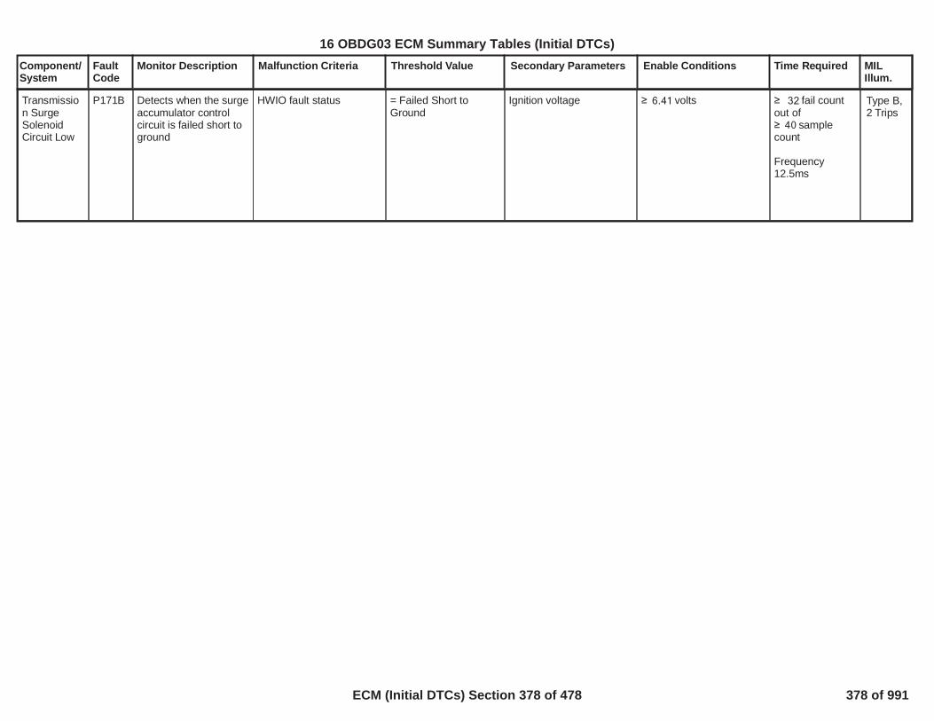
Component/System
FaultCode
Monitor Description Malfunction Criteria Threshold Value Secondary Parameters Enable Conditions Time Required MILIllum.
Transmission SurgeSolenoidCircuit Low
P171B Detects when the surgeaccumulator controlcircuit is failed short toground
HWIO fault status = Failed Short toGround
Ignition voltage volts6.41 fail count32out of sample40
count
Frequency12.5ms
Type B,2 Trips
380
16 OBDG03 ECM Summary Tables (Initial DTCs)
ECM (Initial DTCs) Section 378 of 478 378 of 991

Component/System
FaultCode
Monitor Description Malfunction Criteria Threshold Value Secondary Parameters Enable Conditions Time Required MILIllum.
Transmission SurgeSolenoidCircuit High
P171C Detects when the surgeaccumulator controlcircuit is failed short topower
HWIO fault status = Failed Short toPower
Ignition voltage volts6.41 fail count out6of sa mple count8
Frequency12.5ms
Type B,2 Trips
381
16 OBDG03 ECM Summary Tables (Initial DTCs)
ECM (Initial DTCs) Section 379 of 478 379 of 991

Component/System
FaultCode
Monitor Description Malfunction Criteria Threshold Value Secondary Parameters Enable Conditions Time Required MILIllum.
Transmission SurgeAccumulatorSystemPerformance
P171D Detects when the surgeaccumulator system isnot capable ofsupplying adaquatehydraulic pressureduring the autostart.The diagnostic willmonitor transmissionclutch slip during theautostart event as theprimary malfunctioncriteria.
Transmission turbinespeed is greater thanpredicted turbine speedduring autostart event
P171D predictedturbine speed error
Refer to "TransmissionSupporting Tables" fordetails
PRNDL state defaulted
Transmission shift leverposition
Propulsion system active
Ignition voltageIgnition voltage
Transmission fluid tempTransmission fluid temp
Hybrid stateAutoStop duration min
During autostop Enginespeed was
****************************If above conditions aremet then the followingmust occur:
Turbine speed
Engine speed
Hydraulic pressure delaytime
If above conditions aremet then increment time-out timer.Time-out timer
Note: The initial fail
= False
= Forward range A
= True
volts9.00volts31.99
°C0.00°C110.00
= Engine offseconds1.20
rpm5.00
rpm13.00
rpm450.00
P171D hydraulicpressure delay
Refer to "TransmissionSupporting Tables" fordetails
seconds0.38
counts12(initial fail count)Frequency=12.5ms
Once the abovecounts areachieved thenincrement thefinal fail counteronce. The finalfail counter canonly incrementonce perautostart event
counts (final3fail counter)
If above counteris greater thanthreshold thenreport DTCfailed.
Frequency =12.5ms
Type B,2 Trips
382
16 OBDG03 ECM Summary Tables (Initial DTCs)
ECM (Initial DTCs) Section 380 of 478 380 of 991

Component/System
FaultCode
Monitor Description Malfunction Criteria Threshold Value Secondary Parameters Enable Conditions Time Required MILIllum.
counter must achieve it'sfail threshold in less thanthe time-out time.
*****************************If vehicle is launchedthen:
Transmission Ratio
Trans Ratio band (1st gr)Trans Ratio band (1st gr)
Trans Ratio band (2-6)Trans Ratio band (2-6)
Valid transmission ratioachieved time
OR
If vehicle is not launchedbut autostart occurs then:
Turbine speed
Turbine speed less thenabove threshold for
Note: During an autostartevent the lack of hydraulicpressure will result inmomentary clutch slip inthe C1234 clutch. Afterthe clutch slip event, themain transmission pumpand clutch will gaincapacity, clutch slip will go
=P171D transmissionforward gear ratios
Refer to "TransmissionSupporting Tables" fordetails
pct1.12pct0.88
pct1.07pct0.93
seconds0.50
rpm5.00
seconds0.50
383
16 OBDG03 ECM Summary Tables (Initial DTCs)
ECM (Initial DTCs) Section 381 of 478 381 of 991

Component/System
FaultCode
Monitor Description Malfunction Criteria Threshold Value Secondary Parameters Enable Conditions Time Required MILIllum.
to zero. If the vehicle islaunching (moving) then avalid transmission ratiocan be achieved. Or if thebrake is continuallyapplied and an autostartoccurs naturally, then noratio can be measured. Inthis case turbine speedwill return to near zerorpm.*****************************
DTCs not set CrankSensor_FATransmission OutputShaft Angular VelocityValidityTransmission TurbineAngular Velocity ValidityTransmission OilTemperature ValidityP171AP171BP171CU0101P182EP1915
384
16 OBDG03 ECM Summary Tables (Initial DTCs)
ECM (Initial DTCs) Section 382 of 478 382 of 991

Component/System
FaultCode
Monitor Description Malfunction Criteria Threshold Value Secondary Parameters Enable Conditions Time Required MILIllum.
Fuel LevelSensor 2Performance
(For use onvehicles withmechanicaltransferpump dualfuel tanks)
P2066 This DTC will detect afuel sender stuck inrange in the secondaryfuel tank.
******************************Fuel Level in Primary andSecondary Tanks Remainin an Unreadable Rangetoo Long******************************This subtest is used
If fuel volume in primarytank isand fuel volume insecondary tank isand remains in thiscondition forof fuel consumed by theengine.
OR******************************Fuel Level is in aReadable Range for bothPrimary and SecondaryTanks too Long******************************This subtest is not used
Volume in primary tank isand volume in secondarytank isand remains in thiscondition for
OR******************************Distance Traveled withouta Secondary Fuel LevelChange
liters25.5
< liters8.3
liters19.9
< liters26
> liters9
seconds3,630
Engine Running
No active DTCs: VehicleSpeedSensor_FA
250 ms / sample Type B,2 Trips
385
16 OBDG03 ECM Summary Tables (Initial DTCs)
ECM (Initial DTCs) Section 383 of 478 383 of 991

Component/System
FaultCode
Monitor Description Malfunction Criteria Threshold Value Secondary Parameters Enable Conditions Time Required MILIllum.
******************************If the vehicle is driven withthe fuel consumed by theengine ofwithout the secondary fuellevel changing by liters,3then the sender must bestuck.
liters22
Volume in secondary tank liters8.7
386
16 OBDG03 ECM Summary Tables (Initial DTCs)
ECM (Initial DTCs) Section 384 of 478 384 of 991

Component/System
FaultCode
Monitor Description Malfunction Criteria Threshold Value Secondary Parameters Enable Conditions Time Required MILIllum.
Fuel LevelSensor 2Circuit LowVoltage
(For use onvehicles withdual fueltanks)
P2067 This DTC will detect afuel sender stuck out ofrange low in thesecondary fuel tank.
Fuel level Sender % of 5Vrange < %10
failures out100of samples125
100 ms / sample
Type B,2 Trips
387
16 OBDG03 ECM Summary Tables (Initial DTCs)
ECM (Initial DTCs) Section 385 of 478 385 of 991

Component/System
FaultCode
Monitor Description Malfunction Criteria Threshold Value Secondary Parameters Enable Conditions Time Required MILIllum.
Fuel LevelSensor 2Circuit HighVoltage
(For use onvehicles withdual fueltanks)
P2068 This DTC will detect afuel sender stuck out ofrange low in thesecondary fuel tank.
Fuel level Sender % of 5Vrange > %60
failures out100of samples125
100 ms / sample
Type B,2 Trips
388
16 OBDG03 ECM Summary Tables (Initial DTCs)
ECM (Initial DTCs) Section 386 of 478 386 of 991

Component/System
FaultCode
Monitor Description Malfunction Criteria Threshold Value Secondary Parameters Enable Conditions Time Required MILIllum.
IntakeCamshaftActuatorSolenoidCircuit Low–Bank 1
P2088 Diagnoses the VVTsystem high side drivercircuit for circuit faults.
The ECM detects that thecommanded state of thedriver and the actual stateof the control circuit donot match.
Short to ground: 0.5 to a voltage
source within theVehicle GroundVoltage Range relativeto PWRGND
System supply voltage
Output driver iscommanded on
Ignition switch is in crankor run position
> Volts11.00 100failures out of100samples
250 ms /sample,continuous
Type B,2 Trips
389
16 OBDG03 ECM Summary Tables (Initial DTCs)
ECM (Initial DTCs) Section 387 of 478 387 of 991
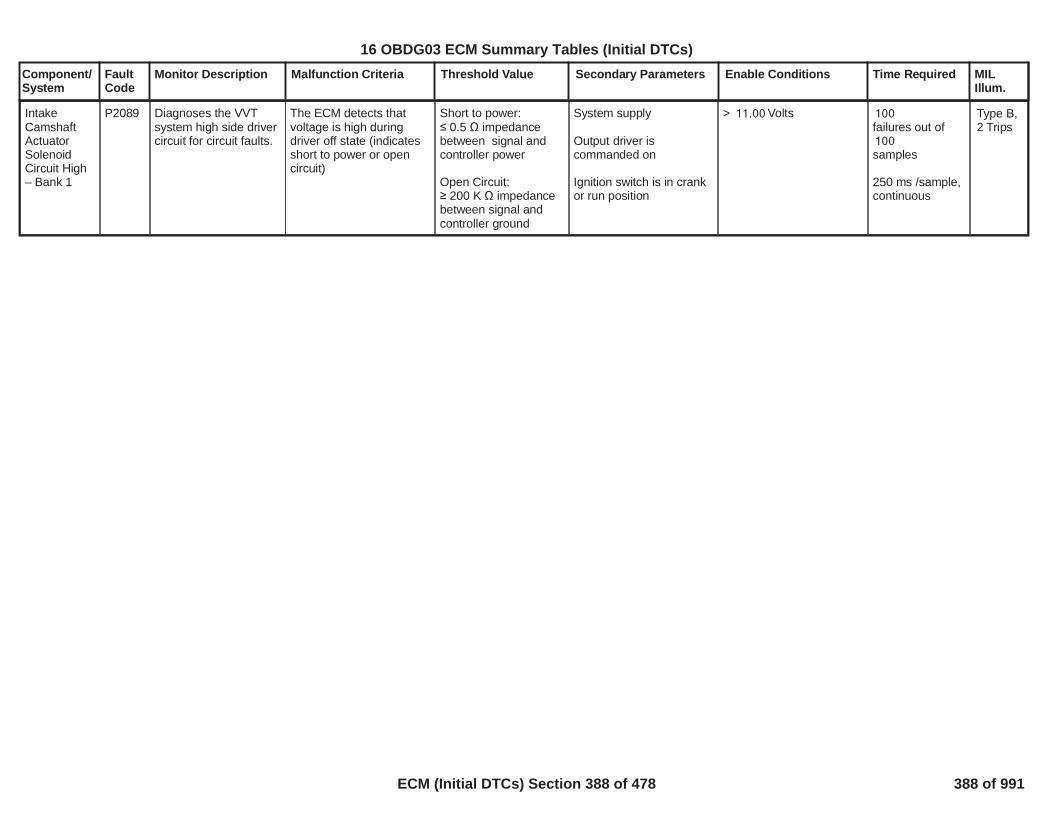
Component/System
FaultCode
Monitor Description Malfunction Criteria Threshold Value Secondary Parameters Enable Conditions Time Required MILIllum.
IntakeCamshaftActuatorSolenoidCircuit High– Bank 1
P2089 Diagnoses the VVTsystem high side drivercircuit for circuit faults.
The ECM detects thatvoltage is high duringdriver off state (indicatesshort to power or opencircuit)
Short to power: 0.5 impedance
between signal andcontroller power
Open Circuit: 200 K impedance
between signal andcontroller ground
System supply
Output driver iscommanded on
Ignition switch is in crankor run position
> Volts11.00 100failures out of100samples
250 ms /sample,continuous
Type B,2 Trips
390
16 OBDG03 ECM Summary Tables (Initial DTCs)
ECM (Initial DTCs) Section 388 of 478 388 of 991

Component/System
FaultCode
Monitor Description Malfunction Criteria Threshold Value Secondary Parameters Enable Conditions Time Required MILIllum.
ExhaustCamshaftActuatorSolenoidCircuit Low –Bank 1
P2090 Diagnoses the VVTsystem high side drivercircuit for circuit faults.
The ECM detects that thecommanded state of thedriver and the actual stateof the control circuit donot match.
Short to ground: 0.5 to a voltage
source within theVehicle GroundVoltage Range relativeto PWRGND
System supply voltage
Output driver iscommanded on
Ignition switch is in crankor run position
> Volts11.00 100failures out of100samples
250 ms /sample,continuous
Type B,2 Trips
391
16 OBDG03 ECM Summary Tables (Initial DTCs)
ECM (Initial DTCs) Section 389 of 478 389 of 991

Component/System
FaultCode
Monitor Description Malfunction Criteria Threshold Value Secondary Parameters Enable Conditions Time Required MILIllum.
ExhaustCamshaftActuatorSolenoidCircuit High– Bank 1
P2091 Diagnoses the VVTsystem high side drivercircuit for circuit faults.
The ECM detects thatvoltage is high duringdriver off state (indicatesshort to power or opencircuit)
Short to power: 0.5 impedance
between signal andcontroller power
Open Circuit: 200 K impedance
between signal andcontroller ground
System supply voltage
Output driver iscommanded on
Ignition switch is in crankor run position
> Volts11.00 100failures out of100samples
250 ms /sample,continuous
Type B,2 Trips
392
16 OBDG03 ECM Summary Tables (Initial DTCs)
ECM (Initial DTCs) Section 390 of 478 390 of 991

Component/System
FaultCode
Monitor Description Malfunction Criteria Threshold Value Secondary Parameters Enable Conditions Time Required MILIllum.
PostCatalyst FuelTrim SystemLow LimitBank 1 (TooRich)
P2096 Determines if the postcatalyst O2 sensorbased fuel controlsystem has utilized allor most of it's low limitauthority, indicating arich exhaust gascondition.Note: If the postcatalyst O2 voltage istoo rich, the postcatalyst O2 integraloffset control isdecreased. Thisresults in lean bias fuelcontrol in an attempt tocorrect the richcondition. A perfectlybalanced controlsystem (no rich or leanbias required) isrepresented by anintegral offset value of“0” and a post catalystO2 sensor that is withinit's optimal operatingrange (neither rich norlean). An integral offsetvalue < 0 is indicativeof the control systemreacting to a rich postcatalyst O2 sensor. Ifthe failure is such thatthe control systemutilizes all or most of itsavailable authority, thenP2096 will set.
Rich Fail counter
High Vapor Feature:The diagnostic is at risk ofreporting a false fail whenexcessively High Vapor(HV) conditions arepresent. This HVcondition is indicatedwhen the purge valve isopen AND percent vaporis >= % for >=18 5.0seconds.
Diagnosis resumes if thepurge valve is closed ORthe percent vapor is <=
% for >= seconds.14 5.0This was done tominimize disabling thediagnostic for longer thannecessary.
>= counts per300sample counts800
Note: Countersincrement at a rate of10 per second whenenable conditions aremet. If the fail countthreshold is reached, afail is reported and thediagnostic will notreport again until thenext trip. If the samplecount threshold isreached before a fail isreported, a pass isreported, the countersare reset to 0, andevaluation starts again.
The diagnostic is enabledduring:DecelerationIdleCruiseLight AccelerationHeavy Acceleration
Ambient Air PressureEngine AirFlowIntake Manifold PressureInduction Air TemperatureStart-up Coolant Temp.PTOIntrusive diag. fuel control
Long Term SecondaryFuel Trim Enabled(see "Long TermSecondary Fuel TrimEnable Criteria" inSupporting Tables)
High Vapor Conditions
No Fault Active for:
NoNoYesYesYes
>= kPa70>= g/s <=0.0 10,000.0>= kPa <=0 200>= deg. C <=-20 200>= deg. C-20Not ActiveNot Active
Not Present
AmbientAirDefaultAIR System FAEthanol CompositionSensor FAECT_Sensor_FAEGRValveCircuit_FAEGRValvePerformance_FAIAT_SensorFACamSensorAnyLocationFAEvapEmissionSystem_FAEvapFlowDuringNonPurge_FAFuelTankPressureSnsrCkt_FA
Frequency:ContinuousMonitoring in100ms loop.
Countersincrement whenenableconditions aremet. Whensample countthreshold isreached or failthreshold isreached,counters arereset to 0 andstart over.
Type B,2 Trips
393
16 OBDG03 ECM Summary Tables (Initial DTCs)
ECM (Initial DTCs) Section 391 of 478 391 of 991

Component/System
FaultCode
Monitor Description Malfunction Criteria Threshold Value Secondary Parameters Enable Conditions Time Required MILIllum.
The above general enableconditions must be truefor:
Minimum accumulatedcounts in each cellrequired before counterswill increment for that cell:DecelerationIdleCruiseLight AccelerationHeavy Acceleration
(Note: A value in any ofthe above operating"cells" that is an order ofmagnitude (or more)higher than other cells isan indication that thediagnostic is not capableof diagnosing in that cell).
For the cells identified as
EvapPurgeSolenoidCircuit_FAEvapSmallLeak_FAEvapVentSolenoidCircuit_FAFuelInjectorCircuit_FAMAF_SensorFAMAF_SensorTFTKOMAP_SensorFAMAP_EngineVacuumStatusEngineMisfireDetected_FAA/F Imbalance Bank1O2S_Bank_1_Sensor_1_FAO2S_Bank_1_Sensor_2_FA
> seconds2.0
2502500550250
394
16 OBDG03 ECM Summary Tables (Initial DTCs)
ECM (Initial DTCs) Section 392 of 478 392 of 991

Component/System
FaultCode
Monitor Description Malfunction Criteria Threshold Value Secondary Parameters Enable Conditions Time Required MILIllum.
enabled (i.e. thosecontaining a "Yes" at thebeginning of the EnableConditions column), thefail counter will incrementif the sample counterincrementsANDPost oxygen sensorcontrol integral offset (inmV) isDecelerationIdleCruiseLight AccelerationHeavy AccelerationANDPost O2 Voltage isDecelerationIdleCruiseLight AccelerationHeavy Acceleration
(Note: A value in any ofthe above operating"cells" that is greater than900mV is an indicationthat the diagnostic is notcapable of diagnosing inthat cell).
<=(control min.= )-90 -100(control min.= )-90 -100(control min.= )-502 -512(control min.= )-502 -512(control min.= )-502 -512
>mV775mV775mV775mV775mV775
395
16 OBDG03 ECM Summary Tables (Initial DTCs)
ECM (Initial DTCs) Section 393 of 478 393 of 991

Component/System
FaultCode
Monitor Description Malfunction Criteria Threshold Value Secondary Parameters Enable Conditions Time Required MILIllum.
PostCatalyst FuelTrim SystemHigh LimitBank 1 (TooLean)
P2097 Determines if the postcatalyst O2 sensorbased fuel controlsystem has utilized allor most of it's high limitauthority, indicating alean exhaust gascondition.Note: If the postcatalyst O2 voltage istoo lean, the postcatalyst O2 integraloffset control isincreased. This resultsin rich bias fuel controlin an attempt to correctthe lean condition. Aperfectly balancedcontrol system (no richor lean bias required) isrepresented by anintegral offset value of“0” and a post catalystO2 sensor that is withinit's optimal operatingrange (neither rich norlean). An integral offsetvalue > 0 is indicativeof the control systemreacting to a lean postcatalyst O2 sensor. Ifthe failure is such thatthe control systemutilizes all or most of itsavailable authority, thenP2097 will set.
Lean Fail counter
High Vapor Feature:The diagnostic is at risk ofreporting a false fail whenexcessively High Vapor(HV) conditions arepresent. This HVcondition is indicatedwhen the purge valve isopen AND percent vaporis >= % for >=18 5.0seconds.
Diagnosis resumes if thepurge valve is closed ORthe percent vapor is <=
% for >= seconds.14 5.0This was done tominimize disabling thediagnostic for longer thannecessary.
>= counts per300sample counts800
Note: Countersincrement at a rate of10 per second whenenable conditions aremet. If the fail countthreshold is reached, afail is reported and thediagnostic will notreport again until thenext trip. If the samplecount threshold isreached before a fail isreported, a pass isreported, the countersare reset to 0, andevaluation starts again.
Same as P2096 exceptfor the following:
For the cells identified asenabled (i.e. thosecontaining a "Yes" at thebeginning of the EnableConditions for P2096), thefail counter will incrementif the sample counterincrementsANDPost oxygen sensorcontrol integral offset (inmV) isDecelerationIdleCruiseLight AccelerationHeavy AccelerationANDPost O2 Voltage isDecelerationIdleCruiseLight AccelerationHeavy Acceleration
(Note: A value in any ofthe above operating"cells" that is less than100mV is an indicationthat the diagnostic is notcapable of diagnosing inthat cell).
>=(control max.= )38 100(control max.= )38 100(control max.= )825 900(control max.= )825 900(control max.= )825 900
<mV644mV644
mV1,000mV1,000mV1,000
Frequency:ContinuousMonitoring in100ms loop.
Countersincrement whenenableconditions aremet. Whensample countthreshold isreached or failthreshold isreached,counters arereset to 0 andstart over.
Type B,2 Trips
396
16 OBDG03 ECM Summary Tables (Initial DTCs)
ECM (Initial DTCs) Section 394 of 478 394 of 991

Component/System
FaultCode
Monitor Description Malfunction Criteria Threshold Value Secondary Parameters Enable Conditions Time Required MILIllum.
Difference betweenmeasured throttle positionand modeled throttleposition >
OR
Difference betweenmodeled throttle positionand measured throttleposition >
10.00percent
10.00percent
TPS minimum learn is notactive and Throttle isbeing Controlled and(Engine Running orIgnition Voltage > orIgnition Voltage > )
Ignition voltage failure isfalse (P1682)
Run/Crank voltage >6.41
Ignition voltage failure isfalse (P1682)
TPS minimum learn is notactive and Throttle isbeing Controlled
AND
((Engine Running ANDIgnition Voltage > )5.50OR Ignition Voltage >
)11.00
counts;1512.5 ms/count inthe primaryprocessor
ControlModuleThrottleActuatorPositionPerformance
P2101 1) Detect a throttlepositioning error2)Throttle control isdriving the throttle inthe incorrect direction3)Throttle controlexceeds the reducedpower limit
Type A,1 Trips
Throttle Position > 36.21percent
Powertrain Relay voltage> 6.41
TPS minimum learn isactive
counts;1112.5 ms/count inthe primaryprocessor
Throttle Position > 35.21percent
Powertrain Relay voltage> 6.41
Reduced Power is True
counts;1112.5 ms/count inthe primaryprocessor
397
16 OBDG03 ECM Summary Tables (Initial DTCs)
ECM (Initial DTCs) Section 395 of 478 395 of 991

Component/System
FaultCode
Monitor Description Malfunction Criteria Threshold Value Secondary Parameters Enable Conditions Time Required MILIllum.
AcceleratorPedalPosition(APP)Sensor 1 Lo
P2122 Detect a continuous orintermittent short oropen in the APP sensor#1 on Main processor
APP1 Voltage < 0.4625 Run/Crank voltage >6.41
No 5V reference error orfault for # 4 5V referencecircuit (P06A3)
/19 39counts or14counts
continuous; 12.5ms/count in themain processor
Type A,1 Trips
398
16 OBDG03 ECM Summary Tables (Initial DTCs)
ECM (Initial DTCs) Section 396 of 478 396 of 991

Component/System
FaultCode
Monitor Description Malfunction Criteria Threshold Value Secondary Parameters Enable Conditions Time Required MILIllum.
AcceleratorPedalPosition(APP)Sensor 1 Hi
P2123 Detect a continuous orintermittent short oropen in the APP sensor#1 on Main processor
APP1 Voltage > 4.7500 Run/Crank voltage >6.41
No 5V reference error orfault for # 4 5V referencecircuit (P06A3)
/19 39counts or14countscontinuous; 12.5ms/count in themain processor
Type A,1 Trips
399
16 OBDG03 ECM Summary Tables (Initial DTCs)
ECM (Initial DTCs) Section 397 of 478 397 of 991

Component/System
FaultCode
Monitor Description Malfunction Criteria Threshold Value Secondary Parameters Enable Conditions Time Required MILIllum.
AcceleratorPedalPosition(APP)Sensor 2 Lo
P2127 Detect a continuous orintermittent short oropen in the APP sensor#2 on Main processor
APP2 Voltage < 0.3250 Run/Crank voltage >6.41
No 5V reference error orfault for # 4 5V referencecircuit (P0697)
/19 39counts or14countscontinuous; 12.5ms/count in themain processor
Type A,1 Trips
400
16 OBDG03 ECM Summary Tables (Initial DTCs)
ECM (Initial DTCs) Section 398 of 478 398 of 991

Component/System
FaultCode
Monitor Description Malfunction Criteria Threshold Value Secondary Parameters Enable Conditions Time Required MILIllum.
AcceleratorPedalPosition(APP)Sensor 2 Hi
P2128 Detect a continuous orintermittent short oropen in the APP sensor#2 on Main processor
APP2 Voltage > 2.6000 Run/Crank voltage >6.41
No 5V reference error orfault for # 4 5V referencecircuit (P0697)
/19 39counts or14countscontinuous; 12.5ms/count in themain processor
Type A,1 Trips
401
16 OBDG03 ECM Summary Tables (Initial DTCs)
ECM (Initial DTCs) Section 399 of 478 399 of 991

Component/System
FaultCode
Monitor Description Malfunction Criteria Threshold Value Secondary Parameters Enable Conditions Time Required MILIllum.
Difference between TPS1displaced and TPS2displaced >
6.775% offset at min. throttleposition with a linearthreshold to9.746% at max. throttleposition
Run/Crank voltage >6.41
No TPS sensor faults(P0122, P0123, P0222,P0223)
No 5V reference error orfault for # 4 5V referencecircuit (P06A3)
/79 159counts or58countscontinuous;3.125 ms/countin the mainprocessor
ThrottlePosition (TP)Sensor 1-2Correlation
P2135 Detects a continuous orintermittent correlationfault between TPSsensors #1 and #2 onMain processor
Type A,1 Trips
Difference between(normalized min TPS1 )and (normalized minTPS2) >
5.000% Vref
Run/Crank voltage >6.41
No TPS sensor faults(P0122, P0123, P0222,P0223)
No 5V reference error orfault for # 4 5V referencecircuit (P06A3)
/79 159counts or58countscontinuous;3.125 ms/countin the mainprocessor
402
16 OBDG03 ECM Summary Tables (Initial DTCs)
ECM (Initial DTCs) Section 400 of 478 400 of 991

Component/System
FaultCode
Monitor Description Malfunction Criteria Threshold Value Secondary Parameters Enable Conditions Time Required MILIllum.
Difference between APP1displaced and APP2displaced >
5.000% offset at min. pedalposition with a linearthreshold to10.001% at max. pedalposition
Run/Crank voltage >6.41
No APP sensor faults(P2122, P2123,P2127,P2128)
No 5V reference errors orfaulst for # 3 & # 4 5Vreference circuits (P06A3,P0697)
/19 39counts
intermittent or15countscontinuous, 12.5ms/count in themain processor
AcceleratorPedalPosition(APP)Sensor 1-2Correlation
P2138 Detects a continuous orintermittent correlationfault between APPsensors #1 and #2 onMain processor
Type A,1 Trips
Difference between(normalized min APP1 )and (normalized minAPP2) >
5.000% Vref
Run/Crank voltage >6.41
No APP sensor faults(P2122, P2123,P2127,P2128)
No 5V reference errors orfaulst for # 3 & # 4 5Vreference circuits (P06A3,P0697)
/19 39counts
intermittent or15countscontinuous, 12.5ms/count in themain processor
403
16 OBDG03 ECM Summary Tables (Initial DTCs)
ECM (Initial DTCs) Section 401 of 478 401 of 991

Component/System
FaultCode
Monitor Description Malfunction Criteria Threshold Value Secondary Parameters Enable Conditions Time Required MILIllum.
Injector 1high sidecircuitshorted toground
P2147 This DTC DiagnosesInjector 1 high sidedriver circuit for circuitfaults.
Voltage high across HighSide Driver during Onstate indicates short toground
Short to Ground:25 amp >= throughHigh Side Driver
Battery VoltageEngine Run Time
>= Volts11>= Seconds5
P062B not FA or TFTK
10failures out of20samples
100 ms /sampleContinuous
Type A,1 Trips
404
16 OBDG03 ECM Summary Tables (Initial DTCs)
ECM (Initial DTCs) Section 402 of 478 402 of 991

Component/System
FaultCode
Monitor Description Malfunction Criteria Threshold Value Secondary Parameters Enable Conditions Time Required MILIllum.
Injector 1high sidecircuitshorted topower
P2148 This DTC DiagnosesInjector 1 high sidedriver circuit for circuitfaults.
Voltage low across Highside drive during off stateindicates short to power.
Short to Power:? 1 volt between signaland controller power
Battery VoltageEngine Run Time
>= Volts11>= Seconds5
P062B not FA or TFTK
10failures out of20samples
100 ms /sampleContinuous
Type A,1 Trips
405
<
16 OBDG03 ECM Summary Tables (Initial DTCs)
ECM (Initial DTCs) Section 403 of 478 403 of 991

Component/System
FaultCode
Monitor Description Malfunction Criteria Threshold Value Secondary Parameters Enable Conditions Time Required MILIllum.
Injector 2high sidecircuitshorted toground
P2150 This DTC DiagnosesInjector 2 high sidedriver circuit for circuitfaults.
Voltage high across HighSide Driver during Onstate indicates short toground
Short to Ground:25 amp >= throughHigh Side Driver
Battery VoltageEngine Run Time
>= Volts11>= Seconds5
P062B not FA or TFTK
10failures out of20samples
100 ms /sampleContinuous
Type A,1 Trips
406
16 OBDG03 ECM Summary Tables (Initial DTCs)
ECM (Initial DTCs) Section 404 of 478 404 of 991

Component/System
FaultCode
Monitor Description Malfunction Criteria Threshold Value Secondary Parameters Enable Conditions Time Required MILIllum.
Injector 2high sidecircuitshorted topower
P2151 This DTC DiagnosesInjector 2 high sidedriver circuit for circuitfaults.
Voltage low across Highside drive during off stateindicates short to power.
Short to Power:? 1 volt between signaland controller power
Battery VoltageEngine Run Time
>= Volts11>= Seconds5
P062B not FA or TFTK
10failures out of20samples
100 ms /sampleContinuous
Type A,1 Trips
407
<
16 OBDG03 ECM Summary Tables (Initial DTCs)
ECM (Initial DTCs) Section 405 of 478 405 of 991

Component/System
FaultCode
Monitor Description Malfunction Criteria Threshold Value Secondary Parameters Enable Conditions Time Required MILIllum.
Injector 3high sidecircuitshorted toground
P2153 This DTC DiagnosesInjector 3 high sidedriver circuit for circuitfaults.
Voltage high across HighSide Driver during Onstate indicates short toground
Short to Ground:25 amp >= throughHigh Side Driver
Battery VoltageEngine Run Time
>= Volts11>= Seconds5
P062B not FA or TFTK
10failures out of20samples
100 ms /sampleContinuous
Type A,1 Trips
408
16 OBDG03 ECM Summary Tables (Initial DTCs)
ECM (Initial DTCs) Section 406 of 478 406 of 991

Component/System
FaultCode
Monitor Description Malfunction Criteria Threshold Value Secondary Parameters Enable Conditions Time Required MILIllum.
Injector 3high sidecircuitshorted topower
P2154 This DTC DiagnosesInjector 3 high sidedriver circuit for circuitfaults.
Voltage low across Highside drive during off stateindicates short to power.
Short to Power:? 1 volt between signaland controller power
Battery VoltageEngine Run Time
>= Volts11>= Seconds5
P062B not FA or TFTK
10failures out of20samples
100 ms /sampleContinuous
Type A,1 Trips
409
<
16 OBDG03 ECM Summary Tables (Initial DTCs)
ECM (Initial DTCs) Section 407 of 478 407 of 991
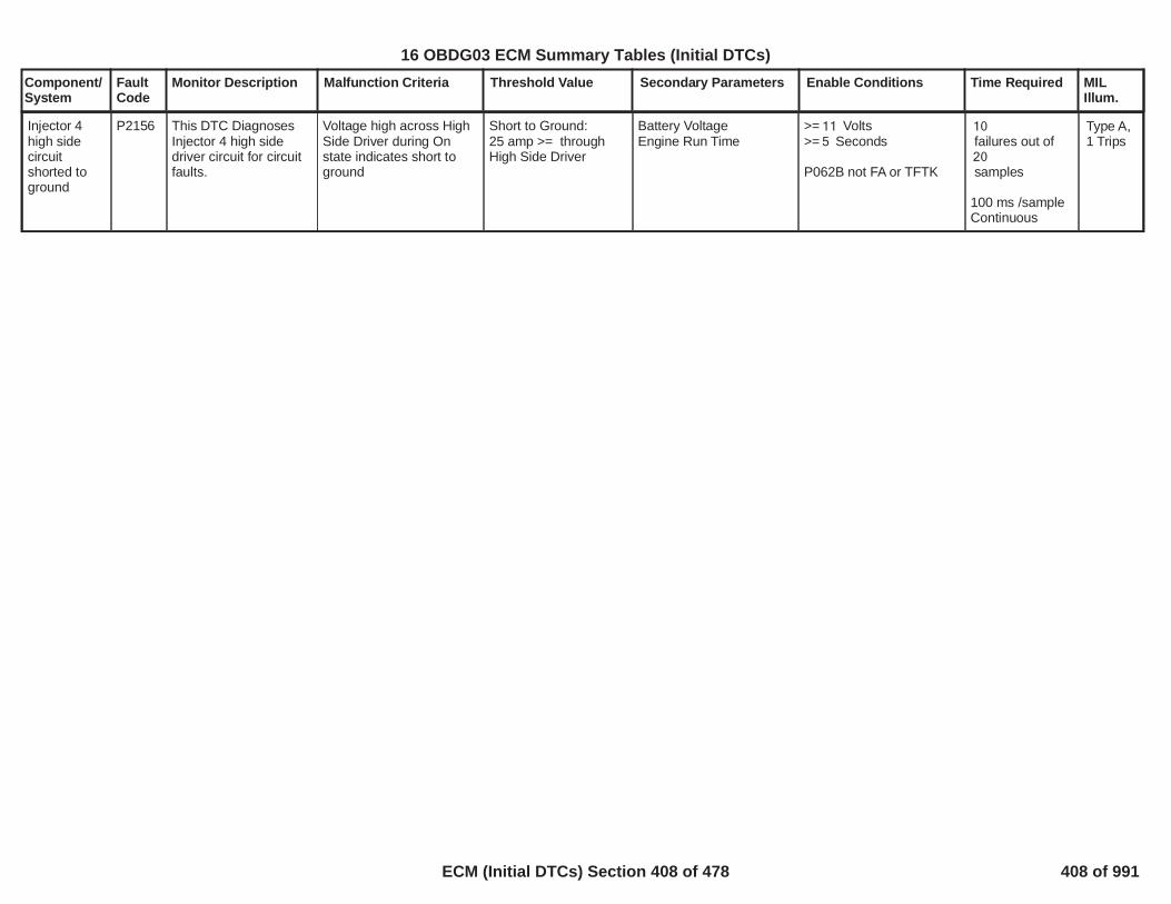
Component/System
FaultCode
Monitor Description Malfunction Criteria Threshold Value Secondary Parameters Enable Conditions Time Required MILIllum.
Injector 4high sidecircuitshorted toground
P2156 This DTC DiagnosesInjector 4 high sidedriver circuit for circuitfaults.
Voltage high across HighSide Driver during Onstate indicates short toground
Short to Ground:25 amp >= throughHigh Side Driver
Battery VoltageEngine Run Time
>= Volts11>= Seconds5
P062B not FA or TFTK
10failures out of20samples
100 ms /sampleContinuous
Type A,1 Trips
410
16 OBDG03 ECM Summary Tables (Initial DTCs)
ECM (Initial DTCs) Section 408 of 478 408 of 991
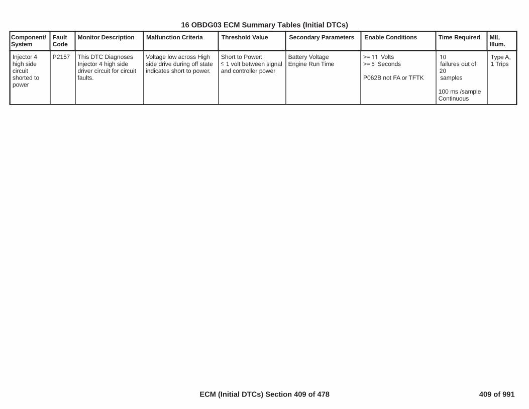
Component/System
FaultCode
Monitor Description Malfunction Criteria Threshold Value Secondary Parameters Enable Conditions Time Required MILIllum.
Injector 4high sidecircuitshorted topower
P2157 This DTC DiagnosesInjector 4 high sidedriver circuit for circuitfaults.
Voltage low across Highside drive during off stateindicates short to power.
Short to Power:? 1 volt between signaland controller power
Battery VoltageEngine Run Time
>= Volts11>= Seconds5
P062B not FA or TFTK
10failures out of20samples
100 ms /sampleContinuous
Type A,1 Trips
411
<
16 OBDG03 ECM Summary Tables (Initial DTCs)
ECM (Initial DTCs) Section 409 of 478 409 of 991

Component/System
FaultCode
Monitor Description Malfunction Criteria Threshold Value Secondary Parameters Enable Conditions Time Required MILIllum.
MinimumThrottlePosition NotLearned
P2176 TP sensors were not inthe minmum learnwindow after multipleattempts to learn theminimum.
During TPS min learn onthe Main processor, TPSVoltage >
AND
Number of learn attempts>
0.5670
10counts
Run/Crank voltage >6.41
TPS minimum learn isactive
No previous TPS minlearn values stored in longterm memory
2.0secs
Type A,1 Trips
412
16 OBDG03 ECM Summary Tables (Initial DTCs)
ECM (Initial DTCs) Section 410 of 478 410 of 991

Component/System
FaultCode
Monitor Description Malfunction Criteria Threshold Value Secondary Parameters Enable Conditions Time Required MILIllum.
Intake AirTemperatureSensor 1 / 2Correlation
P2199 Detects a differencebetween the IAT andIAT2 sensors
ABS (IAT - IAT2) > deg C55.0 Powertrain Relay Voltagefor a time
No Active DTCs:
>= Volts11.0>= seconds0.9
PowertrainRelayFault
failures out40of samples50
1 sample every100 msec
Type B,2 Trips
413
16 OBDG03 ECM Summary Tables (Initial DTCs)
ECM (Initial DTCs) Section 411 of 478 411 of 991

Component/System
FaultCode
Monitor Description Malfunction Criteria Threshold Value Secondary Parameters Enable Conditions Time Required MILIllum.
Bank 1 Air-Fuel RatioImbalance
P219A This monitordetermines if acylinder-to-cylinder air-fuel ratio imbalance ispresent on bank 1.
Filtered Ratio >
Note: The input to thismetric is the pre catalystoxygen sensor voltage.This voltage is used togenerate a Variancemetric that represents thestatistical variation of theO2 sensor voltage over agiven engine cycle. Thismetric is proportional tothe air-fuel ratioimbalance (variance ishigher with an imbalancethan without). Multiplesamples are collected inmaking a decision.
The observed Variance isdependant on enginespeed and load and soeach result is normalizedfor speed and load bycomparing it to a known"good system" result forthat speed and load, andgenerating a Ratio metric.
The Ratio metric iscalculated by selectingthe appropriate thresholdcalibration from a 17x17table (see SupportingTable
)P219A VarianceThreshold Bank1 Tableand subtracting it from themeasured Variance. Theresult is then divided by anormalizer calibration
0.40
If the diagnostic hasreported a failure onthe prior trip, theFiltered Ratio must fallbelow in order to0.35report a pass. Thisfeature prevents thediagnostic fromtoggling betweenfailing and passingwhen the Filtered Ratioremains near the initialfailure threshold of
.0.40
System Voltage
Fuel Level
Engine CoolantTemperature
Cumulative engine runtime
Diagnostic enabled at Idle(regardless of otheroperating conditions)
Engine speed range
Engine speed delta duringa short term sampleperiod
Mass Airflow (MAF) range
Cumulative delta MAFduring a short termsample period
Filtered MAF deltabetween samplesNote: first order lag filtercoefficient applied to MAF= 0.150
Air Per Cylinder (APC)
APC delta during shortterm sample period
Filtered APC delta
no lower than Volts10.0for more than 0.2seconds
> percent AND no10.0fuel level sensor fault
> deg. C-20
> seconds15.0
No
to RPM900 6,000
< RPM150
to g/s8 500
< g/s2
< g/s0.25
to mg/cylinder90 1,200
< mg/cylinder60
Minimum of 1test per trip, upto tests per6trip during RSRor FIR.
The front O2sensor voltage issampled onceper cylinderevent.Therefore, thetime required tocomplete asingle test (whenall enableconditions aremet) decreasesas engine speedincreases. Forexample, 16.50seconds of datais required at1000 rpm whiledouble this timeis required at500 rpm and halfthis time isrequired at 2000rpm. This data iscollected onlywhen enableconditions aremet, and as suchsignificantlymore operatingtime is requiredthan is indicatedabove.Generally, areport will be
Type A,1 Trips
414
16 OBDG03 ECM Summary Tables (Initial DTCs)
ECM (Initial DTCs) Section 412 of 478 412 of 991

Component/System
FaultCode
Monitor Description Malfunction Criteria Threshold Value Secondary Parameters Enable Conditions Time Required MILIllum.
from another 17 x 17 table(see Supporting Table
). ThisP219A NormalizerBank1 Tablequotient is then multipliedby a quality factorcalibration from a 17 x 17table (see SupportingTable
).P219A Quality FactorBank1 TableThis result is referred toas the Ratio. Note thatthe quality factor rangesbetween 0 and 1 andrepresents robustness tofalse diagnosis in thecurrent operating region.Regions with low qualityfactors are not used.
Finally, a EWMA filter isapplied to the Ratio metricto generate the FilteredRatio malfunction criteriametric. Generally, anormal system will resultin a negative FilteredRatio while a failingsystem will result in apositive Filtered Ratio.
The range of the FilteredRatio metric is applicationspecific since both theemissions sensitivity andrelationship betweenimbalance and theVariance metric areapplication specific.
Some applications may
between samplesNote: first order lag filtercoefficient applied to APC= 0.100
Spark Advance
Throttle Area (percent ofmax)
Intake Cam Phaser Angle
Exhaust Cam PhaserAngle
Quality Factor (QF)QF calibrations arelocated in a 17x17 lookuptable versus engine speedand load (see SupportingTable
).P219A Quality FactorBank1 TableQF values less than “1”indicate that we don’thave 4sigma/2sigmarobustness in that region.The quality of the data isdetermined via statisticalanalysis of Variance data.
Fuel Control StatusClosed Loop and LongTerm FT Enabled for:
Device ControlAIR pump
< percent2.00
to degrees5 55
to percent1 200
to degrees0 25
to degrees0 25
>= 0.99
>= seconds1.0(Please see "ClosedLoop EnableClarification" and "LongTerm FT Enable Criteria"in Supporting Tables)
Not activeNot on
made within 5minutes ofoperation.
For RSR or FIR,tests must12
complete beforethe diagnosticcan report.
415
16 OBDG03 ECM Summary Tables (Initial DTCs)
ECM (Initial DTCs) Section 413 of 478 413 of 991

Component/System
FaultCode
Monitor Description Malfunction Criteria Threshold Value Secondary Parameters Enable Conditions Time Required MILIllum.
need to command aunique cam phaser valuebefore performing theabove calculations sincecam phasing has beenshown to have an impacton overall signal quality.This application
thisDoes Not Usefeature.
CASE learnEGREVAPEngine OverSpeedProtectionIdle speed controlPTOInjector base pulse width
O2 learned htr resistance
Rapid Step Response(RSR):RSR will trigger if theRatio result from the lasttest isAND it exceeds the lastFiltered ratio by
Once triggered, thefiltered ratio is reset to:
Fast Initial Response(FIR):FIR will trigger when anNVM reset or code clearoccurs.Once triggered, thefiltered ratio is reset to:
No Fault Active for:
Not activeNot intrusiveNot intrusiveNot Active
NormalNot ActiveAbove min pulse limit
= Valid (the O2 heaterresistance has learnedsince NVM reset)
>= 0.40
>= 0.40
0.00
0.00
EngineMisfireDetected_FAMAP_SensorFAMAF_SensorFAECT_Sensor_FATPS_ThrottleAuthorityDefaultedFuelInjectorCircuit_FA
416
16 OBDG03 ECM Summary Tables (Initial DTCs)
ECM (Initial DTCs) Section 414 of 478 414 of 991

Component/System
FaultCode
Monitor Description Malfunction Criteria Threshold Value Secondary Parameters Enable Conditions Time Required MILIllum.
AIR System FAEvapExcessPurgePsbl_FACamSensorAnyLocationFAFuelTrimSystemB1_FAO2S_Bank_1_Sensor_1_FAO2S_Bank_1_Sensor_2_FAWRAF_Bank_1_FA
417
16 OBDG03 ECM Summary Tables (Initial DTCs)
ECM (Initial DTCs) Section 415 of 478 415 of 991

Component/System
FaultCode
Monitor Description Malfunction Criteria Threshold Value Secondary Parameters Enable Conditions Time Required MILIllum.
Difference between barosensor reading andestimated barowhen distance since lastestimated baro update
OR
Difference between barosensor reading andestimated barowhen distance since lastestimated baro update
> kPa15.0
<= miles0.06
> kPa20.0
> miles0.06
No Active DTCs: AmbPresSnsrCktFAECT_Sensor_Ckt_FAIAT_SensorFAMAF_SensorFAAfterThrottlePressureFATPS_FATPS_Performance_FAVehicleSpeedSensor_FATC_BoostPresSnsrFA
failures out320of samples400
1 sample every12.5 msec
BarometricPressure(BARO)SensorPerformance(single turbo)
P2227 Compares baro sensorto the calculated baroestimate (part throttlecalculation orunthrottled MAP)
Type B,2 Trips
Barometric PressureORBarometric Pressure
OR
ABS(Manifold Pressure -Baro Pressure)ANDABS(Turbocharger BoostPressure - ManifoldPressure)ANDABS(Turbocharger BoostPressure - Baro Pressure)
< kPa50.0
> kPa115.0
> kPa10.0
<= kPa10.0
> kPa10.0
Time between currentignition cycle and the lasttime the engine wasrunning
Engine is not rotating
No Active DTCs:
No Pending DTCs:
> seconds10.0
EngineModeNotRunTimerErrorMAP_SensorCircuitFAAAP_SnsrCktFAAAP2_SnsrCktFA
MAP_SensorCircuitFPAAP_SnsrCktFPAAP2_SnsrCktFP
failures out of4samples5
1 sample every12.5 msec
418
16 OBDG03 ECM Summary Tables (Initial DTCs)
ECM (Initial DTCs) Section 416 of 478 416 of 991
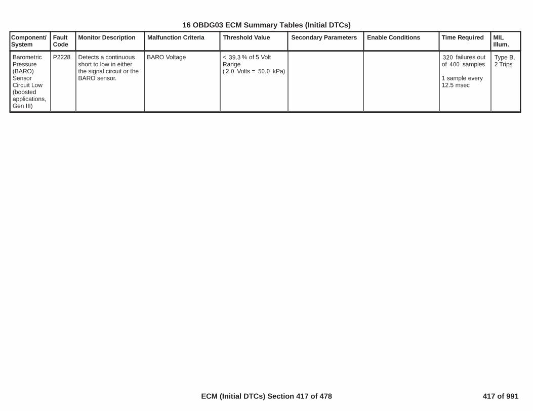
Component/System
FaultCode
Monitor Description Malfunction Criteria Threshold Value Secondary Parameters Enable Conditions Time Required MILIllum.
BarometricPressure(BARO)SensorCircuit Low(boostedapplications,Gen III)
P2228 Detects a continuousshort to low in eitherthe signal circuit or theBARO sensor.
BARO Voltage < % of 5 Volt39.3Range( Volts = kPa)2.0 50.0
failures out320of samples400
1 sample every12.5 msec
Type B,2 Trips
419
16 OBDG03 ECM Summary Tables (Initial DTCs)
ECM (Initial DTCs) Section 417 of 478 417 of 991

Component/System
FaultCode
Monitor Description Malfunction Criteria Threshold Value Secondary Parameters Enable Conditions Time Required MILIllum.
BarometricPressure(BARO)SensorCircuit High(boostedapplications,Gen III)
P2229 Detects an opensensor ground,continuous short tohigh or open in eitherthe signal circuit or theBARO sensor.
BARO Voltage > % of 5 Volt90.0Range( Volts =4.5 115.0kPa)
failures out320of samples400
1 sample every12.5 msec
Type B,2 Trips
420
16 OBDG03 ECM Summary Tables (Initial DTCs)
ECM (Initial DTCs) Section 418 of 478 418 of 991

Component/System
FaultCode
Monitor Description Malfunction Criteria Threshold Value Secondary Parameters Enable Conditions Time Required MILIllum.
BarometricPressure(BARO)SensorCircuitIntermittent
P2230 Detects a noisy orerratic barometricpressure input
String Length
Where:"String Length" = sum of"Diff" calculated over
And where:"Diff" = ABS(currentBARO reading - BAROreading from 12.5milliseconds previous)
> kPa100
consecutive BARO80samples
failures out of4samples5
Each sampletakes 1.0seconds
Type B,2 Trips
421
16 OBDG03 ECM Summary Tables (Initial DTCs)
ECM (Initial DTCs) Section 419 of 478 419 of 991

Component/System
FaultCode
Monitor Description Malfunction Criteria Threshold Value Secondary Parameters Enable Conditions Time Required MILIllum.
O2 SensorPumpingCurrentPerformanceBank 1
P223C This DTC determines ifthe O2 sensor pumpingcurrent has an incorrector out of range value
Fault condition presentwhen the pump current isin any of the fault regionswhen this test is enabledduring DFCO.
The three pumpcurrent fault regionsare:A) Pump current
> ma4.18
B) Pump current<= ma and0.10>= - ma0.10
C) Pump current< ma-0.10
The three fault regionshave individual X out ofY calibrations. Whenthe X out of Y isreached in any regionthis DTC is set.
Note: This DTC willdetect open circuitfaults to the Pumpcurrent, Ref Cellvoltage, Ref Groundand Trim circuits.
Note: A open circuit onthe Pump currentsignal may also set aP0131 DTC.
Note: A short to groundon the trim circuit canset P223C.
B1S1 DTC's Not activethis key cycle
Measure valid status(ASIC)
Controller status (ASIC)
Engine Run or Auto stop
**************************Heater Warm-up delay
ThenWRAF circuit diagnosticdelay (since heater Warm-up delay is complete)**************************WRAF Ref celltemperature
Test starts when time inDFCOTest stops when time inDFCO
P0135, P0030, P0031 orP0032.
= Valid
= Ready
= True
= Complete
>= seconds20.0
>= Deg C628
>= seconds5.0
> seconds12.0
Region A: 224failures out of
samples280
OR
Region B: 224failures out of
samples280
OR
Region C: 100failures out of
samples128
Sample rate is25 msec
Test enabledduring DFCO
Type B,2 Trips
422
16 OBDG03 ECM Summary Tables (Initial DTCs)
ECM (Initial DTCs) Section 420 of 478 420 of 991

Component/System
FaultCode
Monitor Description Malfunction Criteria Threshold Value Secondary Parameters Enable Conditions Time Required MILIllum.
O2 SensorReferenceResistanceOut OfRange Bank1
P223E This DTC determines ifthe O2 sensorreference cell has anincorrect or out ofrange resistance value.
Measured Reference celltemperature
< Deg C700OR> Deg C1,000.0
B1S1 DTC's Not activethis key cycle
Measure valid status(ASIC)
Controller status (ASIC)
Engine Run or Auto stop
**************************Heater Warm-up delayThen
WRAF circuit diagnosticdelay (since heater Warm-up delay is complete)Then
Delay after WRAF circuitdiagnostic delay**************************
P0135, P0030, P0031 orP0032
= Valid
= Ready
= True
= Complete
>= seconds20.0
>= seconds10.0
failures out128of samples160
Sample rate is25 msec
Continuous
Type B,2 Trips
423
16 OBDG03 ECM Summary Tables (Initial DTCs)
ECM (Initial DTCs) Section 421 of 478 421 of 991

Component/System
FaultCode
Monitor Description Malfunction Criteria Threshold Value Secondary Parameters Enable Conditions Time Required MILIllum.
Turbo/SuperChargerBypassValve -MechanicalTurbocharger withwastegate.Notsupercharger withmechanicalcompressor
P2261 Detect Stuck ClosedBypass Valve
When measuring timeaccumulated air massflow derivate boostpressure is high passfilteredwith filter frequency
A failure is detected whenAcc. Filtered Air MassFlow
or
Acc.Der.Filtered boostpressure
< Second,1.000
= Hz10.00
> g/s65.00
> kPa/s500.00
Diagnostic Enabled
Engine Speed
Bypass ValveCommanded OpenDuty Cycle
for at least
Pressure ratio over thecompressor RelativeLimit
Condition keep true for xseconds extra
Negative Transient Active:Relative Boost andPressure derivate
Hyst. Negative Transient:Relative Boost orPressure derivate
No Active DTCs:
True
>= rpm1,500
> %6.00
>= s0.250
> refer toP00C4_P2261_KtBSTD_r_SurgeLimin Supporting Tables
s0.80
>= kPa35.0<= kPa/s-250.0
< kPa0.0> kPa/s10.0
BSTR_b_TurboBypassCktFABSTR_b_BoostSnsrFAMAF_SensorFA
Failed tests out7of Tests10
25ms/ sample
Type B,2 Trips
424
16 OBDG03 ECM Summary Tables (Initial DTCs)
ECM (Initial DTCs) Section 422 of 478 422 of 991

Component/System
FaultCode
Monitor Description Malfunction Criteria Threshold Value Secondary Parameters Enable Conditions Time Required MILIllum.
O2 SensorSignal StuckLean Bank 1Sensor 2
P2270 This DTC determines ifthe post catalyst O2sensor is stuck in anormal lean voltagerange and thereby canno longer be used forpost oxygen sensorfuel control or forcatalyst monitoring.The diagnostic is anintrusive test (duringcoast) which increasesthe delivered fuel toachieve the requiredrich threshold.
Post O2 sensor signal
AND
The Accumulated massair flow monitored duringthe Stuck Lean VoltageTest
< mvolts825
> grams60
No Active DTC's
B1S2 DTC's Not activethis key cycle
System VoltageLearned heater resistance
ICAT MAT Burnoff delay
Green O2S Condition
TPS_ThrottleAuthorityDefaultedECT_Sensor_FAIAT_SensorFAMAF_SensorFAMAP_SensorFAAIR System FAFuelInjectorCircuit_FAFuelTrimSystemB1_FAFuelTrimSystemB2_FAEngineMisfireDetected_FAEthanol CompositionSensor FA
P013A, P013B, P013E,P013F, P2270 or P2271
> Volts10.0= Valid ( the heaterresistance has learnedsince NVM reset, seeenable conditions for"HO2S Heater ResistanceDTC's" )
= Not Valid
= Not Valid, See definitionofMultiple DTC Use_GreenSensor Delay Criteria -AirflowandMultiple DTC Use_GreenSensor Delay Criteria -Limitfor the following locations:B1S2, B2S2 (if applicable)in Supporting Tables tab.
Frequency:Once per tripNote: ifNaPOPD_b_ResetFastRespFunc= FALSE for thegiven Fuel BankORNaPOPD_b_RapidResponseActive = TRUE,multiple tests pertrip are allowed.
Type B,2 Trips
425
16 OBDG03 ECM Summary Tables (Initial DTCs)
ECM (Initial DTCs) Section 423 of 478 423 of 991

Component/System
FaultCode
Monitor Description Malfunction Criteria Threshold Value Secondary Parameters Enable Conditions Time Required MILIllum.
Low Fuel Condition DiagPedal position
Engine Airflow
Closed loop integralClosed Loop Active
EvapEthanol
Post fuel cell
Crankshaft Torque
EGR Intrusive diagnosticAll post sensor heaterdelaysO2S Heater (post sensor)on Time
Predicted Catalyst tempFuel State
=================All of the above met for atleast seconds, and0.0then check the following
Engine Speed to initiallyenable testEngine Speed range tokeep test enabled (after
= False<= %4.0
<= gps <=2 15
<= C/L Int <=0.85 1.07= TRUE(Please see “ClosedLoop EnableClarification” inSupporting Tables).
not in control of purgenot in estimate mode
= Enabled, refer toMultiple DTC Use -Block learn cells toenable Post oxygensensor testsfor additional info.
< Nm100.0
= not active
= not active
>= sec80.0
<= ºC <=500 850= DFCO possible
==================
<= RPM <=950 2,950
426
16 OBDG03 ECM Summary Tables (Initial DTCs)
ECM (Initial DTCs) Section 424 of 478 424 of 991

Component/System
FaultCode
Monitor Description Malfunction Criteria Threshold Value Secondary Parameters Enable Conditions Time Required MILIllum.
initially enabled)
Vehicle Speed to initiallyenable testVehicle Speed range tokeep test enabled (afterinitially enabled)=================All of the above met for atleast seconds, and2.0then the Force Cat Richintrusive stage isrequested.=================During Stuck Lean testthe following must stayTRUE or the test willabort:Commanded FuelCrankshaft Torque
<= RPM <=900 3,050
<= MPH <=40.4 77.7
<= MPH <=35.4 82.0
<= EQR <=0.96 1.08< Nm70.0
427
16 OBDG03 ECM Summary Tables (Initial DTCs)
ECM (Initial DTCs) Section 425 of 478 425 of 991

Component/System
FaultCode
Monitor Description Malfunction Criteria Threshold Value Secondary Parameters Enable Conditions Time Required MILIllum.
O2 SensorSignal StuckRich Bank 1Sensor 2
P2271 This DTC determines ifthe post catalyst O2sensor is stuck in anormal rich voltagerange and thereby canno longer be used forpost oxygen sensorfuel control or forcatalyst monitoring.The diagnostic is anintrusive test whichrequests the DFCOmode to achieve therequired lean threshold.
Post O2 sensor signal
AND
The Accumulated massair flow monitored duringthe Stuck Rich VoltageTest
> mvolts100
> grams25.0
No Active DTC's
B1S2 DTC's Not Activethis key cycle
System VoltageLearned heater resistance
ICAT MAT Burnoff delay
Green O2S Condition
TPS_ThrottleAuthorityDefaultedECT_Sensor_FAIAT_SensorFAMAF_SensorFAMAP_SensorFAAIR System FAFuelInjectorCircuit_FAFuelTrimSystemB1_FAFuelTrimSystemB2_FAEngineMisfireDetected_FAEthanol CompositionSensor FA
P013A, P013B, P013E,P013F or P2270
> Volts10.0= Valid ( the heaterresistance has learnedsince NVM reset, seeenable conditions for"HO2S Heater ResistanceDTC's" )
= Not Valid
= Not Valid, See definitionofMultiple DTC Use_GreenSensor Delay Criteria -AirflowandMultiple DTC Use_GreenSensor Delay Criteria -Limitfor the following locations:B1S2, B2S2 (if applicable)in Supporting Tables tab.
Frequency:Once per tripNote: ifNaPOPD_b_ResetFastRespFunc= FALSE for thegiven Fuel BankORNaPOPD_b_RapidResponseActive = TRUE,multiple tests pertrip are allowed.
Type B,2 Trips
428
16 OBDG03 ECM Summary Tables (Initial DTCs)
ECM (Initial DTCs) Section 426 of 478 426 of 991

Component/System
FaultCode
Monitor Description Malfunction Criteria Threshold Value Secondary Parameters Enable Conditions Time Required MILIllum.
Low Fuel Condition Diag
Fuel State
DTC's Passed
==================After above conditions aremet: DFCO mode iscontinued (wo driverinitiated pedal input).
= False
DFCO possible
= P2270= P013E= P013A
=================
429
16 OBDG03 ECM Summary Tables (Initial DTCs)
ECM (Initial DTCs) Section 427 of 478 427 of 991
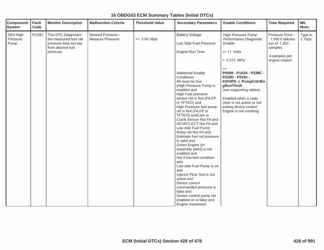
Component/System
FaultCode
Monitor Description Malfunction Criteria Threshold Value Secondary Parameters Enable Conditions Time Required MILIllum.
SIDI HighPressurePump
P228C This DTC Diagnosesthe measured fuel railpressure bias too lowfrom desired fuelpressure.
Desired Pressure -Measure Pressure >= Mpa3.00
Battery Voltage
Low Side Fuel Pressure
Engine Run Time
Additional EnableConditions:All must be true(High Pressure Pump isenabled andHigh Fuel pressuresensor ckt is Not (FA,FPor TFTKO) andHigh Pressure fuel pumpckt is Not (FA,FP orTFTKO) andCam orCrank Sensor Not FA andIAT,IAT2,ECT Not FA andLow side Fuel PumpRelay ckt Not FA andEstimate fuel rail pressureis valid andGreen Engine (Inassembly plant) is notenabled andNot if low fuel conditionandLow side Fuel Pump is onandInjector Flow Test is notactive andDevice controlcommanded pressure isfalse andDevice control pump cktenabled on is false andEngine movement
High Pressure PumpPerformance DiagnosticEnable
>= Volts11
> MPa0.275
>=P0089 - P163A - P228C -P228D - P0191 -KtFHPD_t_PumpCntrlEngRunThrsh(see supporting tables)
Enabled when a codeclear is not active or notexiting device controlEngine is not cranking
Pressure Error -0 failures1,000
out of 1,250samples
samples per4engine rotaion
Type A,1 Trips
430
16 OBDG03 ECM Summary Tables (Initial DTCs)
ECM (Initial DTCs) Section 428 of 478 428 of 991

Component/System
FaultCode
Monitor Description Malfunction Criteria Threshold Value Secondary Parameters Enable Conditions Time Required MILIllum.
detected is true andManufacturers enablecounter is 0)Flex Fuel Sensor Not FAIgnition voltage out ofcorrelation error(P1682)not active
Barometric PressureInlet Air TempFuel Temp
>= KPA70.0>= degC-10.0
<=Temp degC <=-10126
431
16 OBDG03 ECM Summary Tables (Initial DTCs)
ECM (Initial DTCs) Section 429 of 478 429 of 991

Component/System
FaultCode
Monitor Description Malfunction Criteria Threshold Value Secondary Parameters Enable Conditions Time Required MILIllum.
SIDI HighPressurePump
P228D This DTC Diagnosesthe measured fuel railpressure bias too highfrom desired fuelpressure
Desired Pressure -Measure Pressure
<= Mpa-4.00
Battery Voltage
Low Side Fuel Pressure
Engine Run Time
Additional EnableConditions:All must be true(High Pressure Pump isenabled andHigh Fuel pressuresensor ckt is Not (FA,FPor TFTKO) andHigh Pressure fuel pumpckt is Not (FA,FP orTFTKO) andCam or Crank Sensor NotFA andIAT,IAT2,ECT Not FA andLow side Fuel PumpRelay ckt Not FA andEstimate fuel rail pressureis valid andGreen Engine (Inassembly plant) is notenabled andNot if low fuel conditionandLow side Fuel Pump is onandInjector Flow Test is notactive andDevice control
High Pressure PumpPerformance DiagnosticEnable
>= Volts11
> MPa0.275
>=P0089 - P163A - P228C -P228D - P0191 -KtFHPD_t_PumpCntrlEngRunThrsh(see supporting tables)
Enabled when a codeclear is not active or notexiting device controlEngine is not cranking
Pressure Error -failures1,000
out of 1,250samples
samples per4engine rotaion
Type A,1 Trips
432
16 OBDG03 ECM Summary Tables (Initial DTCs)
ECM (Initial DTCs) Section 430 of 478 430 of 991

Component/System
FaultCode
Monitor Description Malfunction Criteria Threshold Value Secondary Parameters Enable Conditions Time Required MILIllum.
commanded pressure isfalse andDevice control pump cktenabled on is false andEngine movementdetected is trueandManufacturers enablecounter is 0)Flex Fuel Sensor Not FAIgnition voltage out ofcorrelation error(P1682)not active
Barometric PressureInlet Air TempFuel Temp
>= KPA70.0>= DegC-10.0
<= Temp degC <=-10126
433
16 OBDG03 ECM Summary Tables (Initial DTCs)
ECM (Initial DTCs) Section 431 of 478 431 of 991

Component/System
FaultCode
Monitor Description Malfunction Criteria Threshold Value Secondary Parameters Enable Conditions Time Required MILIllum.
IGNITIONCONTROL#1 CIRCUITLOW
P2300 Diagnoses Cylinder #1Ignition Control (EST)output driver circuit fora Short to Ground fault
The ECM detects that thecommanded state of thedriver and the actual stateof the control circuit donot match.
Voltage low during driverhigh state (indicatesshort-to-ground)
< 100 impedancebetween signal andcontroller ground
Engine running
Ignition Voltage > 11.0
Failures50out of
Samples63
100 msec rate
Type B,2 Trips
434
16 OBDG03 ECM Summary Tables (Initial DTCs)
ECM (Initial DTCs) Section 432 of 478 432 of 991

Component/System
FaultCode
Monitor Description Malfunction Criteria Threshold Value Secondary Parameters Enable Conditions Time Required MILIllum.
IGNITIONCONTROL#1 CIRCUITHigh
P2301 Diagnoses Cylinder #1Ignition Control (EST)output driver circuit fora Short to Power fault
The ECM detects that thecommanded state of thedriver and the actual stateof the control circuit donot match.
Voltage high during driverlow state (indicates short-to-power)
< 100 impedancebetween signal andcontroller power
Engine running
Ignition Voltage > Volts11.0
Failures50out of
Samples63
100 msec rate
Type B,2 Trips
435
16 OBDG03 ECM Summary Tables (Initial DTCs)
ECM (Initial DTCs) Section 433 of 478 433 of 991

Component/System
FaultCode
Monitor Description Malfunction Criteria Threshold Value Secondary Parameters Enable Conditions Time Required MILIllum.
IGNITIONCONTROL#2 CIRCUITLow
P2303 Diagnoses Cylinder #2Ignition Control (EST)output driver circuit fora Short to Ground fault
The ECM detects that thecommanded state of thedriver and the actual stateof the control circuit donot match.
Voltage low during driverhigh state (indicatesshort-to-ground)
< 100 impedancebetween signal andcontroller ground
Engine running
Ignition Voltage > Volts11.0
Failures50out of
Samples63
100 msec rate
Type B,2 Trips
436
16 OBDG03 ECM Summary Tables (Initial DTCs)
ECM (Initial DTCs) Section 434 of 478 434 of 991

Component/System
FaultCode
Monitor Description Malfunction Criteria Threshold Value Secondary Parameters Enable Conditions Time Required MILIllum.
IGNITIONCONTROL#2 CIRCUITHigh
P2304 Diagnoses Cylinder #2Ignition Control (EST)output driver circuit fora Short to Power fault
The ECM detects that thecommanded state of thedriver and the actual stateof the control circuit donot match.
Voltage high during driverlow state (indicates short-to-power)
< 100 impedancebetween signal andcontroller power
Engine running
Ignition Voltage > Volts11.0
Failures50out of
Samples63
100 msec rate
Type B,2 Trips
437
16 OBDG03 ECM Summary Tables (Initial DTCs)
ECM (Initial DTCs) Section 435 of 478 435 of 991
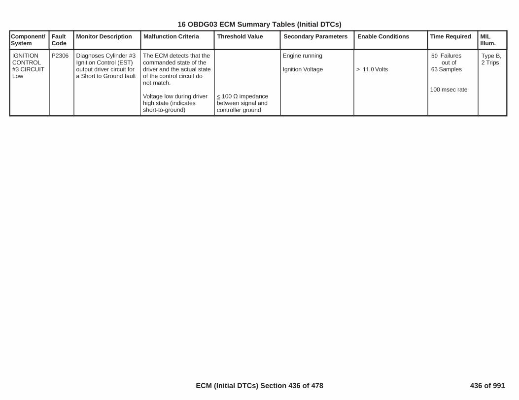
Component/System
FaultCode
Monitor Description Malfunction Criteria Threshold Value Secondary Parameters Enable Conditions Time Required MILIllum.
IGNITIONCONTROL#3 CIRCUITLow
P2306 Diagnoses Cylinder #3Ignition Control (EST)output driver circuit fora Short to Ground fault
The ECM detects that thecommanded state of thedriver and the actual stateof the control circuit donot match.
Voltage low during driverhigh state (indicatesshort-to-ground)
< 100 impedancebetween signal andcontroller ground
Engine running
Ignition Voltage > Volts11.0
Failures50out of
Samples63
100 msec rate
Type B,2 Trips
438
16 OBDG03 ECM Summary Tables (Initial DTCs)
ECM (Initial DTCs) Section 436 of 478 436 of 991

Component/System
FaultCode
Monitor Description Malfunction Criteria Threshold Value Secondary Parameters Enable Conditions Time Required MILIllum.
IGNITIONCONTROL#3 CIRCUITHigh
P2307 Diagnoses Cylinder #3Ignition Control (EST)output driver circuit fora Short to Power fault
The ECM detects that thecommanded state of thedriver and the actual stateof the control circuit donot match.
Voltage high during driverlow state (indicates short-to-power)
< 100 impedancebetween signal andcontroller power
Engine running
Ignition Voltage > Volts11.0
Failures50out of
Samples63
100 msec rate
Type B,2 Trips
439
16 OBDG03 ECM Summary Tables (Initial DTCs)
ECM (Initial DTCs) Section 437 of 478 437 of 991

Component/System
FaultCode
Monitor Description Malfunction Criteria Threshold Value Secondary Parameters Enable Conditions Time Required MILIllum.
IGNITIONCONTROL#4 CIRCUITLow
P2309 Diagnoses Cylinder #4Ignition Control (EST)output driver circuit fora Short to Ground fault
The ECM detects that thecommanded state of thedriver and the actual stateof the control circuit donot match.
Voltage low during driverhigh state (indicatesshort-to-ground)
< 100 impedancebetween signal andcontroller ground
Engine running
Ignition Voltage > Volts11.0
Failures50out of
Samples63
100 msec rate
Type B,2 Trips
440
16 OBDG03 ECM Summary Tables (Initial DTCs)
ECM (Initial DTCs) Section 438 of 478 438 of 991

Component/System
FaultCode
Monitor Description Malfunction Criteria Threshold Value Secondary Parameters Enable Conditions Time Required MILIllum.
IGNITIONCONTROL#4 CIRCUITHigh
P2310 Diagnoses Cylinder #4Ignition Control (EST)output driver circuit fora Short to Power fault
The ECM detects that thecommanded state of thedriver and the actual stateof the control circuit donot match.
Voltage high during driverlow state (indicates short-to-power)
< 100 impedancebetween signal andcontroller power
Engine running
Ignition Voltage > Volts11.0
Failures50out of
Samples63
100 msec rate
Type B,2 Trips
441
16 OBDG03 ECM Summary Tables (Initial DTCs)
ECM (Initial DTCs) Section 439 of 478 439 of 991

Component/System
FaultCode
Monitor Description Malfunction Criteria Threshold Value Secondary Parameters Enable Conditions Time Required MILIllum.
Transmission ControlTorqueRequestCircuit
P2544 Determines if thetorque request from theTCM is valid
Protect error - SerialCommunication message2’s complement not equal($189/$199)
ORRolling count error - SerialCommunication message($189/$199) rolling countindex value
OR
Range Error - SerialCommunication message- ($189/$199) TCMRequested TorqueIncrease
OR
Multi-transition error -Trans torque interventiontype request change
Message <> two'scomplement ofmessage
Message <> previousmessage rolling countvalue + one
> Nm450
Requested torqueintervention typetoggles from notincreasing request toincreasing request
Diagnostic Status
Power Mode
Ignition Voltage
Engine Running
Run/Crank Active
No Serial communicationloss to TCM (U0101)
Enabled
= Run
> volts6.41
= True
> Sec0.50
No loss ofcommunication
>= failures16out of 20samples.
Performed onevery receivedmessage
>= 6Rolling counterrors out of 10samples.
Performed onevery receivedmessage
>= range6errors out of 10samples.
Performed onevery receivedmessage
>= multi-4transitions out of5 samples.Performed every200 msec
Type B,2 Trips
442
16 OBDG03 ECM Summary Tables (Initial DTCs)
ECM (Initial DTCs) Section 440 of 478 440 of 991

Component/System
FaultCode
Monitor Description Malfunction Criteria Threshold Value Secondary Parameters Enable Conditions Time Required MILIllum.
Engine HoodSwitchPerformance
P257D This DTC monitors thehood switch rationality
Hood Switch position is inan invalid position.
Type of Switch:CeHSWR_e_Enumerated
With a discrete typeswitch the hood switchreading is invalid when
With a percentage typeswitch the hood switchreading is invalid in theseranges
With a resistance typeswitch the hood switchreading is invalid in theseranges
With an enumerated typeswitch the hood switchreading is invalid in theseranges
Hood Switch 1 andHood Switch 2 are inthe same state(States not equal isproper function)
% to %93.00 82.70or
% to %70.70 52.80or
% to %27.00 16.70
Ohms to9,578.00Ohms8,858.00
orOhms to3,733.00Ohms2,509.00
orOhms to490.00Ohms463.00
1281 Ohms to1404 Ohms
The diagnostic is enabled
Enabled when Run/Crankis active only,otherwise Run/Crank isnot used as an enable
= (1 indicates enabled)1
= (1 indicates Run/1Crank active enabled)
failed80sampleswithin total100samples
Diagnostic runsin the 12.5 msloop
Type B,2 Trips
443
16 OBDG03 ECM Summary Tables (Initial DTCs)
ECM (Initial DTCs) Section 441 of 478 441 of 991

Component/System
FaultCode
Monitor Description Malfunction Criteria Threshold Value Secondary Parameters Enable Conditions Time Required MILIllum.
Engine HoodSwitch Shortto Ground /Low Voltage
P257E This DTC monitors thehood switch for a shortto ground or lowvoltage condition
Hood Switch positionreading is outsidean expected bounds for
Type of Switch:CeHSWR_e_Enumerated
With a discrete typeswitch the bounds are
With a percentage typeswitch the bound is hoodswitch reading
With a resistance typeswitch the bound is hoodswitch reading
With an enumerated typeswitch the bound is hoodswitch reading
Hood Switch 1 andHood Switch 2 are inthe same state(States not equal isproper function)
<= %16.70
<= Ohms463.00
<= 325 Ohms
The diagnostic is enabled
Enabled when Run/Crankis active only,otherwise Run/Crank isnot used as an enable
= (1 indicates enabled)1
= (1 indicates Run/1Crank active enabled)
failed80sampleswithin total100samples
Diagnostic runsin the 12.5 msloop
Type B,2 Trips
444
16 OBDG03 ECM Summary Tables (Initial DTCs)
ECM (Initial DTCs) Section 442 of 478 442 of 991

Component/System
FaultCode
Monitor Description Malfunction Criteria Threshold Value Secondary Parameters Enable Conditions Time Required MILIllum.
Engine HoodSwitch Shortto Voltage /High Voltage
P257F This DTC monitors thehood switch for a shortto voltage or highvoltage condition
Hood Switch positionreading is outside anexpected bounds for
Type of Switch:CeHSWR_e_Enumerated
With a discrete typeswitch the bounds are
With a percentage typeswitch the bound is hoodswitch reading
With a resistance typeswitch the bound is hoodswitch reading
With an enumerated typeswitch the bound is hoodswitch reading
Hood Switch 1 andHood Switch 2 are inthe same state(States not equal isproper function)
>= %93.00
>= Ohms9,578.00
>= 3620 Ohms
The diagnostic is enabled
Enabled when Run/Crankis active only,otherwise Run/Crank isnot used as an enable
= (1 indicates enabled)1
= (1 indicates Run/1Crank active enabled)
failed80sampleswithin total100samples
Diagnostic runsin the 12.5 msloop
Type B,2 Trips
445
16 OBDG03 ECM Summary Tables (Initial DTCs)
ECM (Initial DTCs) Section 443 of 478 443 of 991

Component/System
FaultCode
Monitor Description Malfunction Criteria Threshold Value Secondary Parameters Enable Conditions Time Required MILIllum.
ControlModulePower OffTimerPerformance
P262B This DTC determines ifthe hardware timerdoes not initialize orcount properly. Thereare two tests to ensureproper functioning ofthe timer: Count UpTest (CUT) and RangeTest (RaTe).
Count Up Test (CUT):Verifies that the HWIOtimer is counting upwith the properincrement.
Range Test (RaTe):When the run/crank isnot active both thehardware and mirrortimers are started. Thetimers are comparedwhen module shutdownis initiated or run/crankbecomes active.
Count Up Test:
Time difference betweenthe current read and theprevious read of the timer
Range Test:
The variation of the HWIOtimer and mirror timer is
> seconds1.50
> %.0.25
Count Up Test:failures out of4samples20
1 sec / sample
Continuous whilerun/crank is notactive and untilcontrollershutdown isinitiated.
Range Test:Once per tripwhen controllershutdown isinitiated or run/crank becomesactive.
Type B,2 Trips
446
16 OBDG03 ECM Summary Tables (Initial DTCs)
ECM (Initial DTCs) Section 444 of 478 444 of 991

Component/System
FaultCode
Monitor Description Malfunction Criteria Threshold Value Secondary Parameters Enable Conditions Time Required MILIllum.
Fuel Pump"A" LowFlow /Performance
P2635 This DTC detectsdegradation in theperformance of theSIDI electronicallyregulated fuel system
Filtered fuel rail pressureerror
<= Low Threshold( see SupportingCalibration tab)
OR
>= High Threshold( see SupportingCalibration tab)
( tabulated result:function of desired fuelrail pressure and fuelflow rate)
a] Fu Rail Pres SnsrCircuit Low Fault Active(DTC P018C)
b] Fu Rail Pres SnsrCircuit High Fault Active(DTC P018D)
c] Fu Rail Pres Snsr PerfFault Active ( DTCP018B)
d] Fu Pump Circuit LowFault Active ( DTC P0231)
e] Fu Pump Circuit HighFault Active ( DTC P0232)
f] Fu Pump Circuit OpenFault Active (DTC P023F)
g] Reference VoltageFault Status (DTCP0641)
h] Fu Pump Driver ControlModule OvertemperatureFault Active (DTC P1255)
j] Barometric PressureSignal Valid (PPEI $4C1)
k] Engine run time
l] Emissions Fuel LevelLow (PPEI $3FB)
m] Fu Pump ControlEnabled
a] <> TRUE
b] <> TRUE
c] <> TRUE
d] <> TRUE
e] <> TRUE
f] <> TRUE
g] <> Active This Key
h] <> TRUE
j] == TRUE(for absolute fuel pressuresensor)
k] >= 30 sec
l] <> TRUE
m] == TRUE
1 sample /12.5 millisec
Type B,2 Trips
447
16 OBDG03 ECM Summary Tables (Initial DTCs)
ECM (Initial DTCs) Section 445 of 478 445 of 991

Component/System
FaultCode
Monitor Description Malfunction Criteria Threshold Value Secondary Parameters Enable Conditions Time Required MILIllum.
n] Fu Pump Control state
p] System Voltage
q] Fuel flow rate
r] Fuel Pressure ControlSystem
n] == Normal
p] 11V< System V <32V
q1] > 0.047 gram/secANDq2] <= Max allowed fuelflow rate (function ofdesired pressure andsystem voltage)(typically11-50 gram/sec)
r1] Not responding tooverperformance due topressure buildup duringDeceleration Fuel Cut OffORr2] Not responding to adecreasing desired fuelpres commnad
448
16 OBDG03 ECM Summary Tables (Initial DTCs)
ECM (Initial DTCs) Section 446 of 478 446 of 991

Component/System
FaultCode
Monitor Description Malfunction Criteria Threshold Value Secondary Parameters Enable Conditions Time Required MILIllum.
MalfunctionIndicatorLamp (MIL)ControlCircuit(ODM) Low
P263A Diagnoses themalfunction indicatorlamp control low sidedriver circuit for circuitfaults.
Voltage low during driveroff state (indicates short-to-ground)
Short to ground: 0.5 impedance
between signal andcontroller ground
Run/Crank Voltage
Remote Vehicle Start isnot active
Voltage volts11.00 failures out of1samples1
50 ms / sample
Type B,No MIL
NO MIL
Note: Incertaincontrollers P0650may alsoset (MILControlOpenCircuit)
449
16 OBDG03 ECM Summary Tables (Initial DTCs)
ECM (Initial DTCs) Section 447 of 478 447 of 991

Component/System
FaultCode
Monitor Description Malfunction Criteria Threshold Value Secondary Parameters Enable Conditions Time Required MILIllum.
MalfunctionIndicatorLamp (MIL)ControlCircuit(ODM) High
P263B Diagnoses themalfunction indicatorlamp control low sidedriver circuit for circuitfaults.
Voltage high during driveron state (indicates shortto power)
Short to power: 0.5 impedance
between signal andcontroller power
Run/Crank Voltage
Remote Vehicle Start isnot active
Voltage volts11.00 failures out of4samples5
50 ms / sample
Type B,No MIL
NO MIL
450
16 OBDG03 ECM Summary Tables (Initial DTCs)
ECM (Initial DTCs) Section 448 of 478 448 of 991

Component/System
FaultCode
Monitor Description Malfunction Criteria Threshold Value Secondary Parameters Enable Conditions Time Required MILIllum.
DC/DCConverterActuatorVoltageSensorCircuit 1 LowVoltage
P3051 Diagnoses the DC/DCConverter ActuatorVoltage Sensor Circuit1 forshort to ground faults.
DC/DC ConverterActuator Voltage RawValue 1
< Volt1 Diagnostic enabled
Run/Crank or Accessory
TRUE
TRUE
failed640samples out of
samples in8006.25 ms loop
Type B,2 Trips
451
16 OBDG03 ECM Summary Tables (Initial DTCs)
ECM (Initial DTCs) Section 449 of 478 449 of 991

Component/System
FaultCode
Monitor Description Malfunction Criteria Threshold Value Secondary Parameters Enable Conditions Time Required MILIllum.
DC/DCConverterActuatorVoltageSensorCircuit 2 LowVoltage
P3052 Diagnoses the DC/DCConverter ActuatorVoltage Sensor Circuit2 forshort to ground faults.
DC/DC ConverterActuator Voltage RawValue 2
< Volt1 Diagnostic enabled
Run/Crank or Accessory
TRUE
TRUE
failed640samples out of
samples in8006.25 ms loop
Type B,2 Trips
452
16 OBDG03 ECM Summary Tables (Initial DTCs)
ECM (Initial DTCs) Section 450 of 478 450 of 991

Component/System
FaultCode
Monitor Description Malfunction Criteria Threshold Value Secondary Parameters Enable Conditions Time Required MILIllum.
DC/DCConverterActuatorVoltageSensorCircuit 1High Voltage
P3053 Diagnoses the DC/DCConverter ActuatorVoltage Sensor Circuit1 forshort to battery faults.
DC/DC ConverterActuator Voltage RawValue 1
> Volt28 Diagnostic enabled
Run/Crank or Accessory
TRUE
TRUE
failed640samples out of
samples in8006.25 ms loop
Type B,2 Trips
453
16 OBDG03 ECM Summary Tables (Initial DTCs)
ECM (Initial DTCs) Section 451 of 478 451 of 991

Component/System
FaultCode
Monitor Description Malfunction Criteria Threshold Value Secondary Parameters Enable Conditions Time Required MILIllum.
DC/DCConverterActuatorVoltageSensorCircuit 2High Voltage
P3054 Diagnoses the DC/DCConverter ActuatorVoltage Sensor Circuit2 forshort to battery faults.
DC/DC ConverterActuator Voltage RawValue 2
> Volt28 Diagnostic enabled
Run/Crank or Accessory
TRUE
TRUE
failed640samples out of
samples in8006.25 ms loop
Type B,2 Trips
454
16 OBDG03 ECM Summary Tables (Initial DTCs)
ECM (Initial DTCs) Section 452 of 478 452 of 991

Component/System
FaultCode
Monitor Description Malfunction Criteria Threshold Value Secondary Parameters Enable Conditions Time Required MILIllum.
Bypass Mode:Absolute value of voltagedifference between DC/DC Converter ActuatorVoltage Raw Value 1 andECM Run/Crank
> Volt1 Diagnostic enabled
Run/Crank or Accessory
Engine runningOR
Engine stopped
TRUE
TRUE
for > loops in 6.25160ms loopfor > loops in 6.25160ms loop
failed640samples out of
samples in800a 6.25 ms loop
DC/DCConverterActuatorVoltage 1Performance
P3055 Detects DC/DCConverter ActuatorVoltage 1 Performanceissues
Type B,2 Trips
Stabilize Mode- Auto-Cranking:Absolute value of voltagedifference between DC/DC Converter ActuatorVoltage Raw Value 1 andECM Run/Crank
> Volt1 Diagnostic enabled
Run/Crank or Accessory
Engine auto-cranking
TRUE
TRUE
for > loops in 6.25 ms0loop
failed16samples out of
samples in a326.25 ms loop
Stablize Mode-Auto-Cranking Events:Number of failed auto-cranking events exceedsthreshold
> failed auto-2cranking events
Diagnostic enabled
Run/Crank or Accessory
Engine auto-cranking
TRUE
TRUE
has occurred
failed auto-2crank events outof consecutive3auto-crankevents
455
16 OBDG03 ECM Summary Tables (Initial DTCs)
ECM (Initial DTCs) Section 453 of 478 453 of 991

Component/System
FaultCode
Monitor Description Malfunction Criteria Threshold Value Secondary Parameters Enable Conditions Time Required MILIllum.
Bypass Mode:Absolute value of voltagedifference between DC/DC Converter ActuatorVoltage Raw Value 2 andECM Run/Crank
> Volt1 Diagnostic enabled
Run/Crank or Accessory
Engine runningOR
Engine stopped
TRUE
TRUE
for > loops in 6.25 ms160loopfor > loops in 6.25 ms160loop
failed640samples out of
samples in800a 6.25 ms loop
DC/DCConverterActuatorVoltage 2Performance
P3056 Detects DC/DCConverter ActuatorVoltage 2 Performanceissues
Type B,2 Trips
Stabilize Mode- Auto-Cranking:Absolute value of voltagedifference between DC/DC Converter ActuatorVoltage Raw Value 2 andECM Run/Crank
> Volt1 Diagnostic enabled
Run/Crank or Accessory
Engine auto-cranking
TRUE
TRUE
for > loops in 6.25 ms0loop
failed16samples out of
samples in a326.25 ms loop
Stablize Mode-Auto-Cranking Events:Number of failed auto-cranking events exceedsthreshold
> failed auto-2cranking events
Diagnostic enabled
Run/Crank or Accessory
Engine auto-cranking
TRUE
TRUE
has occurred
failed auto-2crank events outof consecutive3auto-crankevents
456
16 OBDG03 ECM Summary Tables (Initial DTCs)
ECM (Initial DTCs) Section 454 of 478 454 of 991

Component/System
FaultCode
Monitor Description Malfunction Criteria Threshold Value Secondary Parameters Enable Conditions Time Required MILIllum.
DC/DCConverterIgnitionSwitch Run/StartPositionCiruit HighVoltage
P305B Diagnoses the DC/DCConverter IgnitionSwitch Run/StartPosition circuit forcircuit high faults
DC/DC Converter IgnitionSwitch Run/Start Position
<> ECM IgnitionSwitch Run/StartPosition
Diagnostic enabled
Run/Crank
Accessory
TRUE
FALSE
TRUE
failed320samples out of
samples400
Type B,2 Trips
457
16 OBDG03 ECM Summary Tables (Initial DTCs)
ECM (Initial DTCs) Section 455 of 478 455 of 991

Component/System
FaultCode
Monitor Description Malfunction Criteria Threshold Value Secondary Parameters Enable Conditions Time Required MILIllum.
DC/DCConverterIgnitionSwitch Run/StartPositionCiruit LowVoltage
P305C Diagnoses the DC/DCConverter Switch Run/Start Position circuit forcircuit low faults
DC/DC Converter IgnitionSwitch Run/Start Position
<> ECM IgnitionSwitch Run/StartPosition
Diagnostic enabled
Run/Crank
Accessory
TRUE
TRUE
TRUE
failed640samples out of
samples800
Type B,2 Trips
458
16 OBDG03 ECM Summary Tables (Initial DTCs)
ECM (Initial DTCs) Section 456 of 478 456 of 991

Component/System
FaultCode
Monitor Description Malfunction Criteria Threshold Value Secondary Parameters Enable Conditions Time Required MILIllum.
DC/DCConverterCrankControlCircuit HighVoltage
P305D Diagnoses the DC/DCConverter CrankControl Circuit forcircuit high faults
DC/DC Converter CrankControl
<> ECM Crank Control Diagnostic enabled
Run/Crank
ECM Crank Control
TRUE
TRUE
FALSE
failed640samples out of
samples800
Type B,2 Trips
459
16 OBDG03 ECM Summary Tables (Initial DTCs)
ECM (Initial DTCs) Section 457 of 478 457 of 991

Component/System
FaultCode
Monitor Description Malfunction Criteria Threshold Value Secondary Parameters Enable Conditions Time Required MILIllum.
DC/DCConverterCrankControlCircuit LowVoltage
P305E Diagnoses the DC/DCConverter CrankControl Circuit forcircuit low faults
DC/DC Converter CrankControl
<> ECM Crank Control Diagnostic enabled
Run/Crank or Accessory
ECM Crank Control
TRUE
TRUE
TRUE
failed24samples out of
samples32
Type B,2 Trips
460
16 OBDG03 ECM Summary Tables (Initial DTCs)
ECM (Initial DTCs) Section 458 of 478 458 of 991

Component/System
FaultCode
Monitor Description Malfunction Criteria Threshold Value Secondary Parameters Enable Conditions Time Required MILIllum.
ControlModuleCommunication Bus A Off
U0073 This DTC monitors fora BUS A off condition
Bus off failures exceeds
before the sample time ofis reached
counts5(equivalent to 0.06seconds)
seconds0.81
General Enable Criteria:
U0073
Normal CAN transmissionon Bus A
Device Control
High Voltage VirtualNetwork Management
Ignition Voltage Criteria:
Run/Crank Ignitionvoltage
Power Mode
Off Cycle Enable Criteria:
KeCAND_b_OffKeyCycleDiagEnbl
Ignition Accessory LineandBattery Voltage
General Enable Criteriaand either Ignition VoltageCriteria or Off CycleEnable Criteria met for >
seconds3.0000
CAN hardware is busOFF for
Not Active on Current KeyCycle
Enabled
Not Active
Not Active
> Volts6.41
= run
= 0( 1 indicates enabled)
= Active
> Volts11.00
> seconds0.1625
Diagnostic runsin 12.5 ms loop
Type B,2 Trips
461
16 OBDG03 ECM Summary Tables (Initial DTCs)
ECM (Initial DTCs) Section 459 of 478 459 of 991

Component/System
FaultCode
Monitor Description Malfunction Criteria Threshold Value Secondary Parameters Enable Conditions Time Required MILIllum.
ControlModuleCommunication Bus B Off
U0074 This DTC monitors fora BUS B off condition
Bus off failures exceeds
before the sample time ofis reached
counts5(equivalent to 0.06seconds)
seconds0.81
General Enable Criteria:
U0074
Normal CAN transmissionon Bus B
Device Control
High Voltage VirtualNetwork Management
Ignition Voltage Criteria:
Run/Crank Ignitionvoltage
Power Mode
Off Cycle Enable Criteria:
KeCAND_b_OffKeyCycleDiagEnbl
Ignition Accessory LineandBattery Voltage
General Enable Criteriaand either Ignition VoltageCriteria or Off CycleEnable Criteria met for >
seconds3.0000
CAN hardware is busOFF for
Not Active on Current KeyCycle
Enabled
Not Active
Not Active
> Volts6.41
= run
= 0(1 indicates enabled)
= Active
> Volts11.00
> seconds0.1625
Diagnostic runsin 12.5 ms loop
Type B,2 Trips
462
16 OBDG03 ECM Summary Tables (Initial DTCs)
ECM (Initial DTCs) Section 460 of 478 460 of 991

Component/System
FaultCode
Monitor Description Malfunction Criteria Threshold Value Secondary Parameters Enable Conditions Time Required MILIllum.
LostCommunication With TCM
U0101 This DTC monitors fora loss ofcommunication with thetransmission controlmodule
Message is not receivedfrom controller for
Message $0AB
Message $0BD
Message $0C7
Message $0F9
Message $189
Message $199
Message $19D
Message $1AF
Message $1BE
Message $1BF
Message $1F5
Message $4C9
seconds10.0
seconds10.0
seconds10.0
seconds10.0
seconds10.0
seconds10.0
seconds10.0
seconds10.0
seconds10.0
seconds10.0
seconds10.0
seconds10.0
General Enable Criteria:
U0073
Normal CAN transmissionon Bus A
Device Control
High Voltage VirtualNetwork Management
Ignition Voltage Criteria:
Run/Crank Ignitionvoltage
Power Mode
Off Cycle Enable Criteria:
KeCAND_b_OffKeyCycleDiagEnbl
Ignition Accessory LineandBattery Voltage
General Enable Criteriaand either Ignition VoltageCriteria or Off CycleEnable Criteria met for >
seconds3.0000
Power Mode is inaccessory or run or crankand High Voltage VirtualNetwork Management is
Not Active on Current KeyCycle
Enabled
Not Active
Not Active
> Volts6.41
= run
= 0(1 indicates enabled)
= Active
> Volts11.00
Diagnostic runsin 12.5 ms loop
Type B,2 Trips
463
16 OBDG03 ECM Summary Tables (Initial DTCs)
ECM (Initial DTCs) Section 461 of 478 461 of 991

Component/System
FaultCode
Monitor Description Malfunction Criteria Threshold Value Secondary Parameters Enable Conditions Time Required MILIllum.
not active for
U0101
TCM
> seconds0.4000
Not Active on Current KeyCycle
is present on the bus
464
16 OBDG03 ECM Summary Tables (Initial DTCs)
ECM (Initial DTCs) Section 462 of 478 462 of 991

Component/System
FaultCode
Monitor Description Malfunction Criteria Threshold Value Secondary Parameters Enable Conditions Time Required MILIllum.
LostCommunication WithCruiseControlModule
U0104 This DTC monitors fora loss ofcommunication with theCruise Control Module.
Message is not receivedfrom controller for
Message $2CB
Message $2CD
seconds10.0
seconds10.0
General Enable Criteria:
U0073
Normal CAN transmissionon Bus A
Device Control
High Voltage VirtualNetwork Management
Ignition Voltage Criteria:
Run/Crank Ignitionvoltage
Power Mode
Off Cycle Enable Criteria:
KeCAND_b_OffKeyCycleDiagEnbl
Ignition Accessory LineandBattery Voltage
General Enable Criteriaand either Ignition VoltageCriteria or Off CycleEnable Criteria met for >
seconds3.0000
Power Mode is inaccessory or run or crankand High Voltage Virtual
Not Active on Current KeyCycle
Enabled
Not Active
Not Active
> Volts6.41
= run
= 0(1 indicates enabled)
= Active
> Volts11.00
Diagnostic runsin 12.5 ms loop
Type C,No SVS
465
16 OBDG03 ECM Summary Tables (Initial DTCs)
ECM (Initial DTCs) Section 463 of 478 463 of 991

Component/System
FaultCode
Monitor Description Malfunction Criteria Threshold Value Secondary Parameters Enable Conditions Time Required MILIllum.
Network Management isnot active for
U0104
Cruise Control Module
> seconds0.4000
Not Active on Current KeyCycle
is present on the bus
466
16 OBDG03 ECM Summary Tables (Initial DTCs)
ECM (Initial DTCs) Section 464 of 478 464 of 991

Component/System
FaultCode
Monitor Description Malfunction Criteria Threshold Value Secondary Parameters Enable Conditions Time Required MILIllum.
LostCommunication With Anti-Lock BrakeSystem(ABS)ControlModule
U0121 This DTC monitors fora loss ofcommunication with theAnti-Lock BrakeSystem (ABS) ControlModule (Non-OBDModule ID 243).
Message is not receivedfrom controller for
Message $0C1
Message $0C5
Message $0D1
Message $1C6
Message $1C7
Message $1E9
Message $2F1
Message $2F9
seconds10.0
seconds10.0
seconds10.0
seconds10.0
seconds10.0
seconds10.0
seconds10.0
seconds10.0
General Enable Criteria:
U0073
Normal CAN transmissionon Bus A
Device Control
High Voltage VirtualNetwork Management
Ignition Voltage Criteria:
Run/Crank Ignitionvoltage
Power Mode
Off Cycle Enable Criteria:
KeCAND_b_OffKeyCycleDiagEnbl
Ignition Accessory LineandBattery Voltage
General Enable Criteriaand either Ignition VoltageCriteria or Off CycleEnable Criteria met for >
seconds3.0000
Power Mode is inaccessory or run or crankand High Voltage Virtual
Not Active on Current KeyCycle
Enabled
Not Active
Not Active
> Volts6.41
= run
= 0(1 indicates enabled)
= Active
> Volts11.00
Diagnostic runsin 12.5 ms loop
Type C,No SVS"SpecialType C"
467
16 OBDG03 ECM Summary Tables (Initial DTCs)
ECM (Initial DTCs) Section 465 of 478 465 of 991

Component/System
FaultCode
Monitor Description Malfunction Criteria Threshold Value Secondary Parameters Enable Conditions Time Required MILIllum.
Network Management isnot active for
U0121
Anti-Lock Brake SystemControl Module
> seconds0.4000
Not Active on Current KeyCycle
is present on the bus
468
16 OBDG03 ECM Summary Tables (Initial DTCs)
ECM (Initial DTCs) Section 466 of 478 466 of 991

Component/System
FaultCode
Monitor Description Malfunction Criteria Threshold Value Secondary Parameters Enable Conditions Time Required MILIllum.
LostCommunication WithBody ControlModule
U0140 This DTC monitors fora loss ofcommunication with theBody Control Module.
Message is not receivedfrom controller for
Message $0F1
Message $12A
Message $1E1
Message $1F1
Message $1F3
Message $3C9
Message $3CB
Message $3F1
Message $451
Message $4D7
Message $4E1
Message $4E9
seconds10.0
seconds10.0
seconds10.0
seconds10.0
seconds10.0
seconds10.0
seconds10.0
seconds10.0
seconds10.0
seconds10.0
seconds10.0
seconds10.0
General Enable Criteria:
U0073
Normal CAN transmissionon Bus A
Device Control
High Voltage VirtualNetwork Management
Ignition Voltage Criteria:
Run/Crank Ignitionvoltage
Power Mode
Off Cycle Enable Criteria:
KeCAND_b_OffKeyCycleDiagEnbl
Ignition Accessory LineandBattery Voltage
General Enable Criteriaand either Ignition VoltageCriteria or Off CycleEnable Criteria met for >
seconds3.0000
Power Mode is inaccessory or run or crankand High Voltage VirtualNetwork Management isnot active for
Not Active on Current KeyCycle
Enabled
Not Active
Not Active
> Volts6.41
= run
= 0(1 indicates enabled)
= Active
> Volts11.00
> seconds0.4000
Diagnostic runsin 12.5 ms loop
Type C,No SVS"SpecialType C"
469
16 OBDG03 ECM Summary Tables (Initial DTCs)
ECM (Initial DTCs) Section 467 of 478 467 of 991

Component/System
FaultCode
Monitor Description Malfunction Criteria Threshold Value Secondary Parameters Enable Conditions Time Required MILIllum.
U0140
Body Control Module
Not Active on Current KeyCycle
is present on the bus
470
16 OBDG03 ECM Summary Tables (Initial DTCs)
ECM (Initial DTCs) Section 468 of 478 468 of 991

Component/System
FaultCode
Monitor Description Malfunction Criteria Threshold Value Secondary Parameters Enable Conditions Time Required MILIllum.
LostCommunication WithBatteryMonitorModule
U01B0 This DTC monitors fora loss ofcommunication with theBattery Monitor Moduleon LIN bus
Message is not receivedfrom controller for ECMhas lost communicationover the LIN bus withBattery Monitor Modulefor >= counts3
The following criteria havebeen enabled for
Power Mode
Run/Crank Voltage
>= seconds5.00
=Run
>= Volts11.00
Between 100msand 175ms dueto rate of LINcommunicationto BatteryMonitor Module.
Type B,2 Trips
471
16 OBDG03 ECM Summary Tables (Initial DTCs)
ECM (Initial DTCs) Section 469 of 478 469 of 991

Component/System
FaultCode
Monitor Description Malfunction Criteria Threshold Value Secondary Parameters Enable Conditions Time Required MILIllum.
ControlModuleCommunication LIN Bus 1Off
U1501 This DTC monitors fora LIN bus off condition
LIN bus off failures >= counts3.00 The following criteria havebeen enabled for
Power Mode
Run/Crank Voltage
>= seconds5.00
=Run
>= Volts11.00
Dependent onbus loading.
Type B,2 Trips
472
16 OBDG03 ECM Summary Tables (Initial DTCs)
ECM (Initial DTCs) Section 470 of 478 470 of 991

Component/System
FaultCode
Monitor Description Malfunction Criteria Threshold Value Secondary Parameters Enable Conditions Time Required MILIllum.
LIN Bus 1LostCommunication withDevice 0(Shutter 1)
U1510 This DTC monitors fora loss ofcommunication on theLIN bus with Shutter 1
ECM has lostcommunication over theLIN bus with Device 0 /Shutter 1 for >= counts3.00
The following criteria havebeen enabled for
Power Mode
Run/Crank Voltage
>= seconds5.00
=Run
>= Volts11.00
LIN buscommunicationexecutes in500ms loop
Type B,2 Trips
473
16 OBDG03 ECM Summary Tables (Initial DTCs)
ECM (Initial DTCs) Section 471 of 478 471 of 991
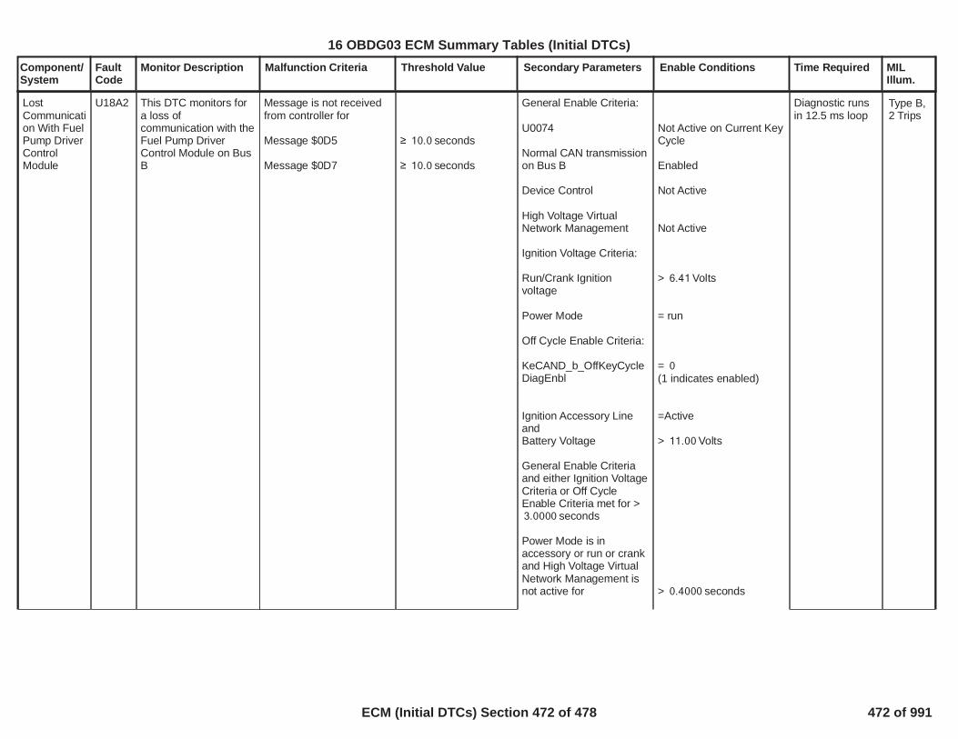
Component/System
FaultCode
Monitor Description Malfunction Criteria Threshold Value Secondary Parameters Enable Conditions Time Required MILIllum.
LostCommunication With FuelPump DriverControlModule
U18A2 This DTC monitors fora loss ofcommunication with theFuel Pump DriverControl Module on BusB
Message is not receivedfrom controller for
Message $0D5
Message $0D7
seconds10.0
seconds10.0
General Enable Criteria:
U0074
Normal CAN transmissionon Bus B
Device Control
High Voltage VirtualNetwork Management
Ignition Voltage Criteria:
Run/Crank Ignitionvoltage
Power Mode
Off Cycle Enable Criteria:
KeCAND_b_OffKeyCycleDiagEnbl
Ignition Accessory LineandBattery Voltage
General Enable Criteriaand either Ignition VoltageCriteria or Off CycleEnable Criteria met for >
seconds3.0000
Power Mode is inaccessory or run or crankand High Voltage VirtualNetwork Management isnot active for
Not Active on Current KeyCycle
Enabled
Not Active
Not Active
> Volts6.41
= run
= 0(1 indicates enabled)
=Active
> Volts11.00
> seconds0.4000
Diagnostic runsin 12.5 ms loop
Type B,2 Trips
474
16 OBDG03 ECM Summary Tables (Initial DTCs)
ECM (Initial DTCs) Section 472 of 478 472 of 991

Component/System
FaultCode
Monitor Description Malfunction Criteria Threshold Value Secondary Parameters Enable Conditions Time Required MILIllum.
U18A2
Fuel Pump Driver ControlModule
Not Active on Current KeyCycle
is present on the bus
475
16 OBDG03 ECM Summary Tables (Initial DTCs)
ECM (Initial DTCs) Section 473 of 478 473 of 991

Component/System
FaultCode
Monitor Description Malfunction Criteria Threshold Value Secondary Parameters Enable Conditions Time Required MILIllum.
LostCommunication With DC/DCConverterControlModule onBus B
U18A7 This DTC monitors fora loss ofcommunication with theDC/DC ConverterControl Module on BusB
Message is not receivedfrom controller for
Message $0A0
Message $1D2
seconds10.0
seconds10.0
General Enable Criteria:
U0074
Normal CAN transmissionon Bus B
Device Control
High Voltage VirtualNetwork Management
Ignition Voltage Criteria:
Run/Crank Ignitionvoltage
Power Mode
Off Cycle Enable Criteria:
KeCAND_b_OffKeyCycleDiagEnbl
Ignition Accessory LineandBattery Voltage
General Enable Criteriaand either Ignition VoltageCriteria or Off CycleEnable Criteria met for >
seconds3.0000
Power Mode is inaccessory or run or crankand High Voltage VirtualNetwork Management isnot active for
Not Active on Current KeyCycle
Enabled
Not Active
Not Active
> Volts6.41
= run
= 0(1 indicates enabled)
=Active
> Volts11.00
> seconds0.4000
Diagnostic runsin 12.5 ms loop
Type B,2 Trips
476
16 OBDG03 ECM Summary Tables (Initial DTCs)
ECM (Initial DTCs) Section 474 of 478 474 of 991

Component/System
FaultCode
Monitor Description Malfunction Criteria Threshold Value Secondary Parameters Enable Conditions Time Required MILIllum.
U18A7
DC/DC Converter ControlModule
Not Active on Current KeyCycle
is present on the bus
477
16 OBDG03 ECM Summary Tables (Initial DTCs)
ECM (Initial DTCs) Section 475 of 478 475 of 991

Component/System
FaultCode
Monitor Description Malfunction Criteria Threshold Value Secondary Parameters Enable Conditions Time Required MILIllum.
LostCommunication with FrontObjectDetectionControlModule
U216A This DTC monitors fora loss ofcommunication with theFront Object DetectionControl Module.
Messages are notreceived from controllerfor
Message $2CB
Message $2CD
Message $2CF
Message $370
seconds10.0
seconds10.0
seconds10.0
seconds10.0
General Enable Criteria:
U0073
Normal CAN transmissionon Bus A
Device Control
High Voltage VirtualNetwork Management
Ignition Voltage Criteria:
Run/Crank Ignitionvoltage
Power Mode
Off Cycle Enable Criteria:
KeCAND_b_OffKeyCycleDiagEnbl
Ignition Accessory Line
andBattery Voltage
General Enable Criteriaand either Ignition VoltageCriteria or Off CycleEnable Criteria met for >
seconds3.0000Power Mode is inaccessory or run or crankand High Voltage VirtualNetwork Management isnot active for
Not Active on Current KeyCycle
Enabled
Not Active
Not Active
> Volts6.41
= run
= 0(1 indicates enabled)
= Active
> Volts11.00
> seconds0.4000
Diagnostic runsin 12.5 ms loop
Type C,No SVS
478
16 OBDG03 ECM Summary Tables (Initial DTCs)
ECM (Initial DTCs) Section 476 of 478 476 of 991
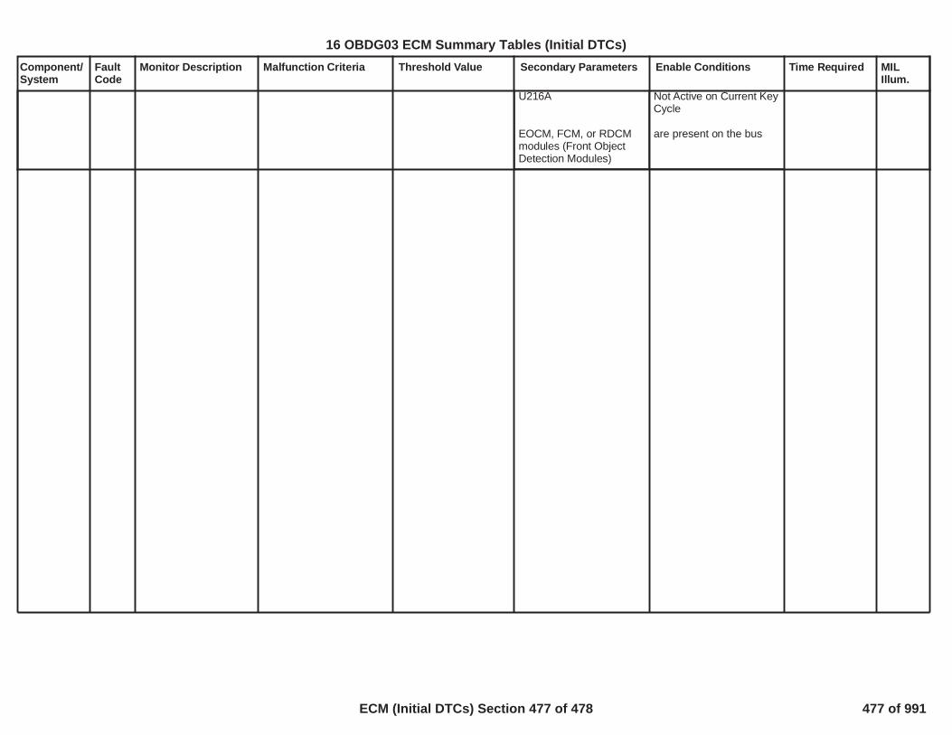
Component/System
FaultCode
Monitor Description Malfunction Criteria Threshold Value Secondary Parameters Enable Conditions Time Required MILIllum.
U216A
EOCM, FCM, or RDCMmodules (Front ObjectDetection Modules)
Not Active on Current KeyCycle
are present on the bus
479
16 OBDG03 ECM Summary Tables (Initial DTCs)
ECM (Initial DTCs) Section 477 of 478 477 of 991

Component/System
FaultCode
Monitor Description Malfunction Criteria Threshold Value Secondary Parameters Enable Conditions Time Required MILIllum.
Fuel PumpDriverControlModule LostCommunication withECM/PCM
U2616 To detect lost serialdata communicationfrom the power drivercontroller to the ECM
Timer - Fuel SystemControl message CAN$0D9 not received( FPPM Received SerialData CommunicationStatus)
t > 10 s( Fu Pmp Pwr Modsmart device reportsFaulted, Not Faulted orIndeterminate)
a) FPPM configurationKeFRPR_e_ChassisFuelPresSysTypeb) Fault statedetermination enabledc) Run_Crank statusd) FPPM Control StatusAlive Rolling Count resulte) FPPM Diagnosticfeedback receivedf) System Voltage
a) ==CeFRPR_e_ECM_FPPM_Sysb) == TRUEc) == Actived) == Valide) == TRUEf) 9v < Sys Voltage > 32v
64 failures / 80samples
1 sample / 12.5millisec
Type B,2 Trips
480
16 OBDG03 ECM Summary Tables (Initial DTCs)
ECM (Initial DTCs) Section 478 of 478 478 of 991

Component/System
FaultCode
Monitor Description Malfunction Criteria Threshold Value Secondary Parameters Enable Conditions Time Required MILIllum.
ManifoldAbsolutePressureSensorCircuit Low
P0107 Detects a continuousshort to low or open ineither the signal circuitor the MAP sensor.
MAP Voltage < % of 5 Volt3.0Range(This is equal to 0.15Volts or kPa)3.5
Continuous failures out320of samples400
1 sample every12.5 msec
Type B,2 Trips
1
16 OBDG03 ECM Summary Tables (Unique DTCs)
ECM (Unique DTCs) Section 1 of 224 479 of 991

Component/System
FaultCode
Monitor Description Malfunction Criteria Threshold Value Secondary Parameters Enable Conditions Time Required MILIllum.
ManifoldAbsolutePressureSensorCircuit High
P0108 Detects an opensensor ground orcontinuous short tohigh in either the signalcircuit or the MAPsensor.
MAP Voltage > % of 5 Volt90.0Range(This is equal to 4.50Volts, or kPa)115.0
Continuous failures out320of samples400
1 sample every12.5 msec
Type B,2 Trips
2
16 OBDG03 ECM Summary Tables (Unique DTCs)
ECM (Unique DTCs) Section 2 of 224 480 of 991

Component/System
FaultCode
Monitor Description Malfunction Criteria Threshold Value Secondary Parameters Enable Conditions Time Required MILIllum.
Injector 1Open Circuit- (PFI)
P0201 This DTC DiagnosesInjector 1 low sidedriver circuit for circuitfaults.
Voltage low during driveroff state indicates short-to-ground or open circuit
Open circuit:? 200 K ? impedancebetween signal andcontroller ground
Powertrain Relay Voltagewithin range for a duration
Engine Running
>= Volts11>= Seconds1
>= Seconds0
20failures out of25samples
100 ms /sampleContinuous
Type B,2 Trips
Note: Incertaincontrollers P0261may alsoset(Injector1 ShorttoGround)
3
16 OBDG03 ECM Summary Tables (Unique DTCs)
ECM (Unique DTCs) Section 3 of 224 481 of 991

Component/System
FaultCode
Monitor Description Malfunction Criteria Threshold Value Secondary Parameters Enable Conditions Time Required MILIllum.
Injector 2Open Circuit- (PFI)
P0202 This DTC DiagnosesInjector 2 low sidedriver circuit for circuitfaults.
Voltage low during driveroff state indicates short-to-ground or open circuit
Open circuit:? 200 K ? impedancebetween signal andcontroller ground
Powertrain Relay Voltagewithin range for a duration
Engine Running
>= Volts11>= Seconds1
>= Seconds0
20failures out of25samples
100 ms /sampleContinuous
Type B,2 Trips
Note: Incertaincontrollers P0264may alsoset(Injector2 ShorttoGround)
4
>
16 OBDG03 ECM Summary Tables (Unique DTCs)
ECM (Unique DTCs) Section 4 of 224 482 of 991

Component/System
FaultCode
Monitor Description Malfunction Criteria Threshold Value Secondary Parameters Enable Conditions Time Required MILIllum.
Injector 3Open Circuit- (PFI)
P0203 This DTC DiagnosesInjector 3 low sidedriver circuit for circuitfaults.
Voltage low during driveroff state indicates short-to-ground or open circuit
Open circuit:? 200 K ? impedancebetween signal andcontroller ground
Powertrain Relay Voltagewithin range for a duration
Engine Running
>= Volts11>= Seconds1
>= Seconds0
20failures out of25samples
100 ms /sampleContinuous
Type B,2 Trips
Note: Incertaincontrollers P0267may alsoset(Injector3 ShorttoGround)
5
>
16 OBDG03 ECM Summary Tables (Unique DTCs)
ECM (Unique DTCs) Section 5 of 224 483 of 991

Component/System
FaultCode
Monitor Description Malfunction Criteria Threshold Value Secondary Parameters Enable Conditions Time Required MILIllum.
Injector 4Open Circuit- (PFI)
P0204 This DTC DiagnosesInjector 4 low sidedriver circuit for circuitfaults.
Voltage low during driveroff state indicates short-to-ground or open circuit
Open circuit:? 200 K ? impedancebetween signal andcontroller ground
Powertrain Relay Voltagewithin range for a duration
Engine Running
>= Volts11>= Seconds1
>= Seconds0
20failures out of25samples
100 ms /sampleContinuous
Type B,2 Trips
Note: Incertaincontrollers P0270may alsoset(Injector4 ShorttoGround)
6
>
16 OBDG03 ECM Summary Tables (Unique DTCs)
ECM (Unique DTCs) Section 6 of 224 484 of 991

Component/System
FaultCode
Monitor Description Malfunction Criteria Threshold Value Secondary Parameters Enable Conditions Time Required MILIllum.
Injector 1Low sidecircuitshorted toground (PFI)
P0261 This DTC DiagnosesInjector 1 low sidedriver circuit for circuitfaults.
Voltage low during driveroff state indicates short-to-ground or open circuit
Short to ground:? 0.5 ? impedancebetween signal andcontroller ground
Powertrain Relay Voltagewithin range for a duration
Engine Running
>= Volts11>= Seconds1
>= Seconds0
20failures out of25samples
100 ms /sampleContinuous
Type B,2 Trips
Note: Incertaincontrollers P0201may alsoset(Injector1 OpenCircuit)
7
16 OBDG03 ECM Summary Tables (Unique DTCs)
ECM (Unique DTCs) Section 7 of 224 485 of 991

Component/System
FaultCode
Monitor Description Malfunction Criteria Threshold Value Secondary Parameters Enable Conditions Time Required MILIllum.
Injector 1Low sidecircuitshorted topower (PFI)
P0262 This DTC DiagnosesInjector 1 low sidedriver circuit for circuitfaults.
Voltage high during driveron state indicates short topower
Short to power:? 0.5 ? impedancebetween signal andcontroller power
Powertrain Relay Voltagewithin range for a duration
Engine Running
>= Volts11>= Seconds1
>= Seconds0
20failures out of25samples
100 ms /sampleContinuous
Type B,2 Trips
8
<
16 OBDG03 ECM Summary Tables (Unique DTCs)
ECM (Unique DTCs) Section 8 of 224 486 of 991

Component/System
FaultCode
Monitor Description Malfunction Criteria Threshold Value Secondary Parameters Enable Conditions Time Required MILIllum.
Injector 2Low sidecircuitshorted toground (PFI)
P0264 This DTC DiagnosesInjector 2 low sidedriver circuit for circuitfaults.
Voltage low during driveroff state indicates short-to-ground or open circuit
Short to ground:? 0.5 ? impedancebetween signal andcontroller ground
Powertrain Relay Voltagewithin range for a duration
Engine Running
>= Volts11>= Seconds1
>= Seconds0
20failures out of25samples
100 ms /sampleContinuous
Type B,2 Trips
Note: Incertaincontrollers P0202may alsoset(Injector2 OpenCircuit)
9
<
16 OBDG03 ECM Summary Tables (Unique DTCs)
ECM (Unique DTCs) Section 9 of 224 487 of 991

Component/System
FaultCode
Monitor Description Malfunction Criteria Threshold Value Secondary Parameters Enable Conditions Time Required MILIllum.
Injector 2Low sidecircuitshorted topower (PFI)
P0265 This DTC DiagnosesInjector 2 low sidedriver circuit for circuitfaults.
Voltage high during driveron state indicates short topower
Short to power:? 0.5 ? impedancebetween signal andcontroller power
Powertrain Relay Voltagewithin range for a duration
Engine Running
>= Volts11>= Seconds1
>= Seconds0
20failures out of25samples
100 ms /sampleContinuous
Type B,2 Trips
10
<
16 OBDG03 ECM Summary Tables (Unique DTCs)
ECM (Unique DTCs) Section 10 of 224 488 of 991

Component/System
FaultCode
Monitor Description Malfunction Criteria Threshold Value Secondary Parameters Enable Conditions Time Required MILIllum.
Injector 3Low sidecircuitshorted toground (PFI)
P0267 This DTC DiagnosesInjector 3 low sidedriver circuit for circuitfaults.
Voltage low during driveroff state indicates short-to-ground or open circuit
Short to ground:? 0.5 ? impedancebetween signal andcontroller ground
Powertrain Relay Voltagewithin range for a duration
Engine Running
>= Volts11>= Seconds1
>= Seconds0
20failures out of25samples
100 ms /sampleContinuous
Type B,2 Trips
Note: Incertaincontrollers P0203may alsoset(Injector3 OpenCircuit)
11
<
16 OBDG03 ECM Summary Tables (Unique DTCs)
ECM (Unique DTCs) Section 11 of 224 489 of 991

Component/System
FaultCode
Monitor Description Malfunction Criteria Threshold Value Secondary Parameters Enable Conditions Time Required MILIllum.
Injector 3Low sidecircuitshorted topower (PFI)
P0268 This DTC DiagnosesInjector 3 low sidedriver circuit for circuitfaults.
Voltage high during driveron state indicates short topower
Short to power:? 0.5 ? impedancebetween signal andcontroller power
Powertrain Relay Voltagewithin range for a duration
Engine Running
>= Volts11>= Seconds1
>= Seconds0
20failures out of25samples
100 ms /sampleContinuous
Type B,2 Trips
12
<
16 OBDG03 ECM Summary Tables (Unique DTCs)
ECM (Unique DTCs) Section 12 of 224 490 of 991

Component/System
FaultCode
Monitor Description Malfunction Criteria Threshold Value Secondary Parameters Enable Conditions Time Required MILIllum.
Injector 4Low sidecircuitshorted toground (PFI)
P0270 This DTC DiagnosesInjector 4 low sidedriver circuit for circuitfaults.
Voltage low during driveroff state indicates short-to-ground or open circuit
Short to ground:? 0.5 ? impedancebetween signal andcontroller ground
Powertrain Relay Voltagewithin range for a duration
Engine Running
>= Volts11>= Seconds1
>= Seconds0
20failures out of25samples
100 ms /sampleContinuous
Type B,2 Trips
Note: Incertaincontrollers P0204may alsoset(Injector4 OpenCircuit)
13
<
16 OBDG03 ECM Summary Tables (Unique DTCs)
ECM (Unique DTCs) Section 13 of 224 491 of 991

Component/System
FaultCode
Monitor Description Malfunction Criteria Threshold Value Secondary Parameters Enable Conditions Time Required MILIllum.
Injector 4Low sidecircuitshorted topower (PFI)
P0271 This DTC DiagnosesInjector 4 low sidedriver circuit for circuitfaults.
Voltage high during driveron state indicates short topower
Short to power:? 0.5 ? impedancebetween signal andcontroller power
Powertrain Relay Voltagewithin range for a duration
Engine Running
>= Volts11>= Seconds1
>= Seconds0
20failures out of25samples
100 ms /sampleContinuous
Type B,2 Trips
14
<
16 OBDG03 ECM Summary Tables (Unique DTCs)
ECM (Unique DTCs) Section 14 of 224 492 of 991

Component/System
FaultCode
Monitor Description Malfunction Criteria Threshold Value Secondary Parameters Enable Conditions Time Required MILIllum.
SecondaryAIR IncorrectAirflow (forsingle valvesystems)
P0411 Detects an insufficientflow condition.This testis run during Phase 1(AIR pumpcommanded On, ValvecommandedOpen).Leaksdownstream of thevalve are detected viaan evaluation ofaverage pressure errorand average “StringLength”(SL) – a termthat represents theabsolute pressure deltaaccumulated every6.25ms, then averagedover the duration of thetest. Low SL values areindicative ofdownstream leaks orblockages.
Average Pressure Erroror
OR the followingString Length (SL) Test:
Average Pressure Erroror
andthe Average String Length
NOTE: Average PressureError is the averagedifference between thepredicted pressure andthe measured pressure
> kPa5.0< kPa-4.9
> kPa1.0< kPa-1.0
<P0411 SL ThresholdBank 1 Table
BAROInlet Air TempCoolant TempEngine off timeSystem VoltageMAP notEngine SpeedMAF not
SL Stability time
SL RPM range
No active DTCs:
> kPa60> deg C-10.0> deg C <-10.0 80.0> seconds3,600.0> Volts <10.0 32.0< kPa for sec20 2.0< RPM5,000> gm/s for sec50 3.0
> seconds Bank 15.0> seconds Bank 25.0
< RPM or >6,000 6,500
AIRSystemPressureSensor FAAIRValveControlCircuit FAAIRPumpControlCircuitFAMAF_SensorFAAmbientAirDefaultIAT_SensorFAECT_Sensor_FAEngineMisfireDetected_FACatalystSysEfficiencyLoB1_FACatalystSysEfficiencyLoB2_FAP0606IgnitionOutputDriver_FAFuelInjectorCircuit_FA
Phase 1Conditional testweight > 7.0seconds
Total 'StringLength'accumulationtime:> sec10.0Bank1> sec10.0Bank2
Frequency: Onceper trip when AIRpumpcommanded On
Conditional testweight iscalculated bymultiplying thefollowingFactors:
,
P0411 Phase 1Baro TestWeight Factor
,
P0411 Phase 1MAF TestWeight Factor
,
P0411 Phase 1System VoltTest WeightFactorP0411 Phase 1Amb Temp TestWeight Factor(see SupportingTables)
Type B,2 Trips
15
16 OBDG03 ECM Summary Tables (Unique DTCs)
ECM (Unique DTCs) Section 15 of 224 493 of 991

Component/System
FaultCode
Monitor Description Malfunction Criteria Threshold Value Secondary Parameters Enable Conditions Time Required MILIllum.
SecondaryAIR SolenoidControlCircuit Open
P0412 Diagnoses theSecondary AIRSolenoid Control LowSide Driver circuit forcircuit faults
Voltage low during driveroff state (indicates opencircuit)
Open Circuit:>= 200K Ohmsimpedance betweensignal and controllerground
Powertrain Relay Voltage >= volts11.00 failures out20of samples25
250ms / sample
Type B,2 Trips
Note: IncertaincontrollersP041Fmay alsoset(Secondary AIRsolenoidcontrolcircuitlowvoltage)
16
16 OBDG03 ECM Summary Tables (Unique DTCs)
ECM (Unique DTCs) Section 16 of 224 494 of 991

Component/System
FaultCode
Monitor Description Malfunction Criteria Threshold Value Secondary Parameters Enable Conditions Time Required MILIllum.
SecondaryAIR PumpControlCircuit Open
P0418 Diagnoses theSecondary AIR PumpControl Low SideDriver circuit for circuitfaults
Voltage low during driveroff state (indicates opencircuit)
Open Circuit:>= 200K Ohmsimpedance betweensignal and controllerground
Powertrain relay Voltage >= volts11.00 failures out20of samples25
250ms / sample
Type B,2 Trips
Note: Incertaincontrollers P2257may alsoset(Secondary AIRPumpControlCircuitLowVoltage)
17
16 OBDG03 ECM Summary Tables (Unique DTCs)
ECM (Unique DTCs) Section 17 of 224 495 of 991

Component/System
FaultCode
Monitor Description Malfunction Criteria Threshold Value Secondary Parameters Enable Conditions Time Required MILIllum.
SecondaryAIR SolenoidControlCircuit LowVoltage
P041F Diagnoses theSecondary AIRSolenoid Control LowSide Driver circuit forcircuit faults
Voltage low during driveroff state (indicates short-to-ground)
Short to ground:<= 0.5 Ohmsimpedance betweensignal and controllerground
Powertrain relay Voltage >= volts11.00 failures out20of samples25
250ms / sample
Type B,2 Trips
Note: Incertaincontrollers P0412may alsoset(Secondary AIRsolenoidcontrolcircuitOpen)
18
16 OBDG03 ECM Summary Tables (Unique DTCs)
ECM (Unique DTCs) Section 18 of 224 496 of 991

Component/System
FaultCode
Monitor Description Malfunction Criteria Threshold Value Secondary Parameters Enable Conditions Time Required MILIllum.
SecondaryAIR SolenoidControlCircuit HighVoltage
P044F Diagnoses theSecondary AIRSolenoid Control LowSide Driver circuit forcircuit faults
Voltage high during driveron state (indicates short-to-power)
Short to power:<= 0.5 Ohmsimpedance betweensignal and controllerpower
Powertrain relay Voltage >= volts11.00 failures out20of samples25
250ms / sample
Type B,2 Trips
19
16 OBDG03 ECM Summary Tables (Unique DTCs)
ECM (Unique DTCs) Section 19 of 224 497 of 991

Component/System
FaultCode
Monitor Description Malfunction Criteria Threshold Value Secondary Parameters Enable Conditions Time Required MILIllum.
Cooling Fan2 RelayControlCircuit Open(ODM)
P0481 Diagnoses the coolingfan 2 relay control lowside driver circuit forcircuit faults
Voltage low during driveroff state (indicates opencircuit)
Open Circuit: 200 K impedance
between signal andcontroller ground
Powertrain Relay Voltage Voltage volts11.00 failures out of50samples63
100 ms / sample
Type B,2 Trips
Note: Incertaincontrollers P0693may alsoset (Fan2 ShorttoGround)
20
16 OBDG03 ECM Summary Tables (Unique DTCs)
ECM (Unique DTCs) Section 20 of 224 498 of 991

Component/System
FaultCode
Monitor Description Malfunction Criteria Threshold Value Secondary Parameters Enable Conditions Time Required MILIllum.
IntakeManifoldTuning (IMT)ValveSolenoidControlCircuit Bank1
P0660 Diagnoses the IntakeManifold Tuning (IMT)Valve low side drivercircuit for circuit faults
Voltage low during driveroff state (indicates opencircuit)
Open Circuit: >= 200KOhms impedancebetween signal andcontroller ground
Powertrain Relay VoltageEngine Speed
>= Volts11.00>= RPM400
failures out40of samples50
1 sample every12.5 msec
Type B,2 Trips
Note incertaincontrollers P0661may alsoset(IntakeManifoldTuning(IMT)ValveSolenoidControlCircuitLowVoltageBank 1)
21
16 OBDG03 ECM Summary Tables (Unique DTCs)
ECM (Unique DTCs) Section 21 of 224 499 of 991

Component/System
FaultCode
Monitor Description Malfunction Criteria Threshold Value Secondary Parameters Enable Conditions Time Required MILIllum.
IntakeManifoldTuning (IMT)ValveSolenoidControlCircuit LowVoltageBank 1
P0661 Diagnoses the IntakeManifold Tuning (IMT)Valve low side drivercircuit for circuit faults
Voltage low during driveroff state (indicates short-to-ground or open circuit)
Short to ground: <= 0.5Ohms impedancebetween signal andcontroller ground
Open Circuit: >= 200KOhms impedancebetween signal andcontroller ground
Powertrain Relay VoltageEngine Speed
>= Volts11.00>= RPM400
failures out40of samples50
1 sample every12.5 msec
Type B,2 Trips
Note incertaincontrollers P0660may alsoset(IntakeManifoldTuning(IMT)ValveSolenoidControlCircuitBank 1)
22
16 OBDG03 ECM Summary Tables (Unique DTCs)
ECM (Unique DTCs) Section 22 of 224 500 of 991

Component/System
FaultCode
Monitor Description Malfunction Criteria Threshold Value Secondary Parameters Enable Conditions Time Required MILIllum.
IntakeManifoldTuning (IMT)ValveSolenoidControlCircuit HighVoltageBank 1
P0662 Diagnoses the IntakeManifold Tuning (IMT)Valve low side drivercircuit for circuit faults
Voltage low during driveron state (indicates short-to-power)
Short to power: <= 0.5Ohms impedancebetween signal andcontroller power
Powertrain Relay VoltageEngine Speed
>= Volts11.00>= RPM400
failures out40of samples50
1 sample every12.5 msec
Type B,2 Trips
23
16 OBDG03 ECM Summary Tables (Unique DTCs)
ECM (Unique DTCs) Section 23 of 224 501 of 991
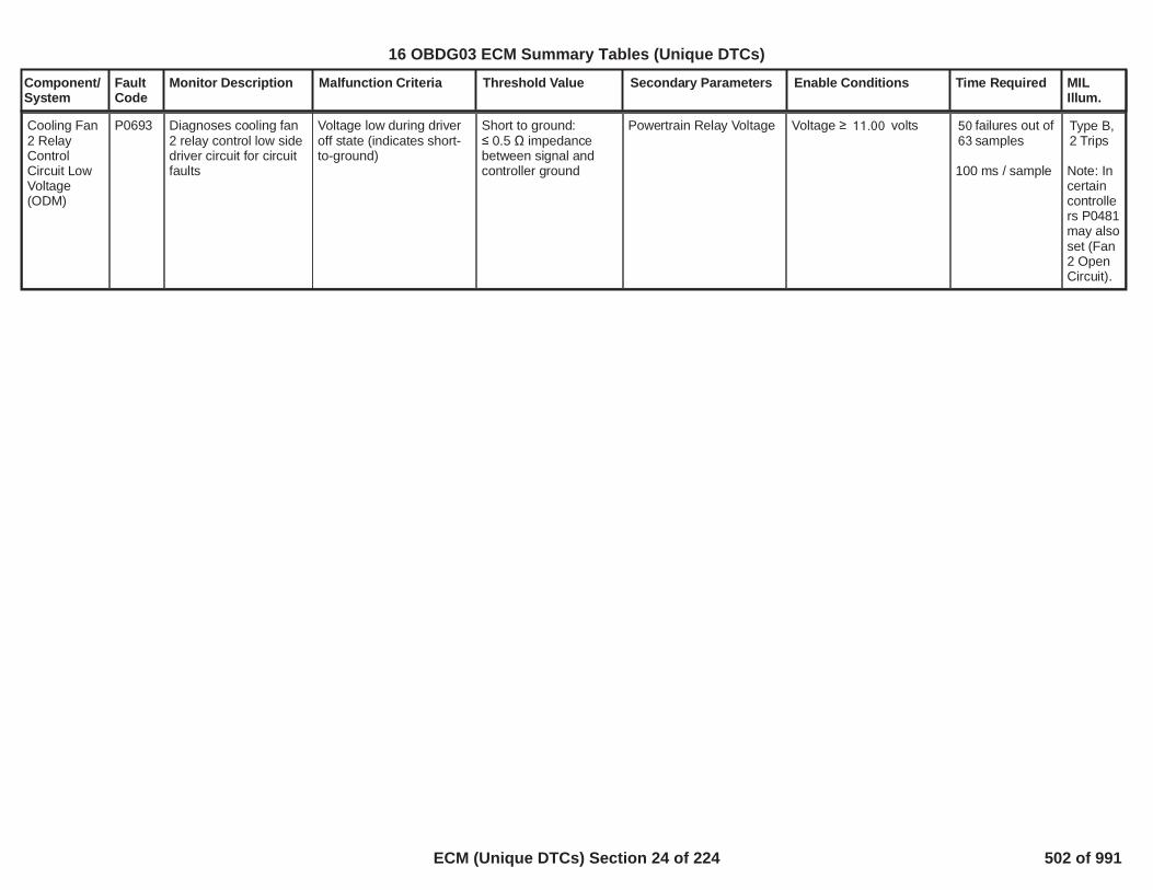
Component/System
FaultCode
Monitor Description Malfunction Criteria Threshold Value Secondary Parameters Enable Conditions Time Required MILIllum.
Cooling Fan2 RelayControlCircuit LowVoltage(ODM)
P0693 Diagnoses cooling fan2 relay control low sidedriver circuit for circuitfaults
Voltage low during driveroff state (indicates short-to-ground)
Short to ground: 0.5 impedance
between signal andcontroller ground
Powertrain Relay Voltage Voltage volts11.00 failures out of50samples63
100 ms / sample
Type B,2 Trips
Note: Incertaincontrollers P0481may alsoset (Fan2 OpenCircuit).
24
16 OBDG03 ECM Summary Tables (Unique DTCs)
ECM (Unique DTCs) Section 24 of 224 502 of 991

Component/System
FaultCode
Monitor Description Malfunction Criteria Threshold Value Secondary Parameters Enable Conditions Time Required MILIllum.
Cooling Fan2 RelayControlCircuit HighVoltage(ODM)
P0694 Diagnoses the coolingfan 2 relay control lowside driver circuit forcircuit faults
Voltage high during driveron state (indicates shortto power)
Short to power: 0.5 impedance
between signal andcontroller power
Powertrain Relay Voltage Voltage volts11.00 failures out of50samples63
100 ms / sample
Type B,2 Trips
25
16 OBDG03 ECM Summary Tables (Unique DTCs)
ECM (Unique DTCs) Section 25 of 224 503 of 991

Component/System
FaultCode
Monitor Description Malfunction Criteria Threshold Value Secondary Parameters Enable Conditions Time Required MILIllum.
IntakeManifoldTuning (IMT)Valve StuckOpen
P2070 Detects an IntakeManifold Tuning Valvethat is stuck in the openposition
Time after the closecommand without theIntake Manifold TuningValve reaching the closedposition >= seconds5.00
Intake Manifold TuningValve is commandedclosed
No Active DTCs: P0660P0661P0662P2077P2078
failures out320of samples400
1 sample every12.5 msec
Type B,2 Trips
26
16 OBDG03 ECM Summary Tables (Unique DTCs)
ECM (Unique DTCs) Section 26 of 224 504 of 991

Component/System
FaultCode
Monitor Description Malfunction Criteria Threshold Value Secondary Parameters Enable Conditions Time Required MILIllum.
IntakeManifoldTuning (IMT)Valve StuckClosed
P2071 Detects an IntakeManifold Tuning Valvethat is stuck in theclosed position
Time after the opencommand without theIntake Manifold TuningValve reaching the openposition >= seconds5.00
Intake Manifold TuningValve is commandedclosed
No Active DTCs: P0660P0661P0662P2077P2078
failures out320of samples400
1 sample every12.5 msec
Type B,2 Trips
27
16 OBDG03 ECM Summary Tables (Unique DTCs)
ECM (Unique DTCs) Section 27 of 224 505 of 991
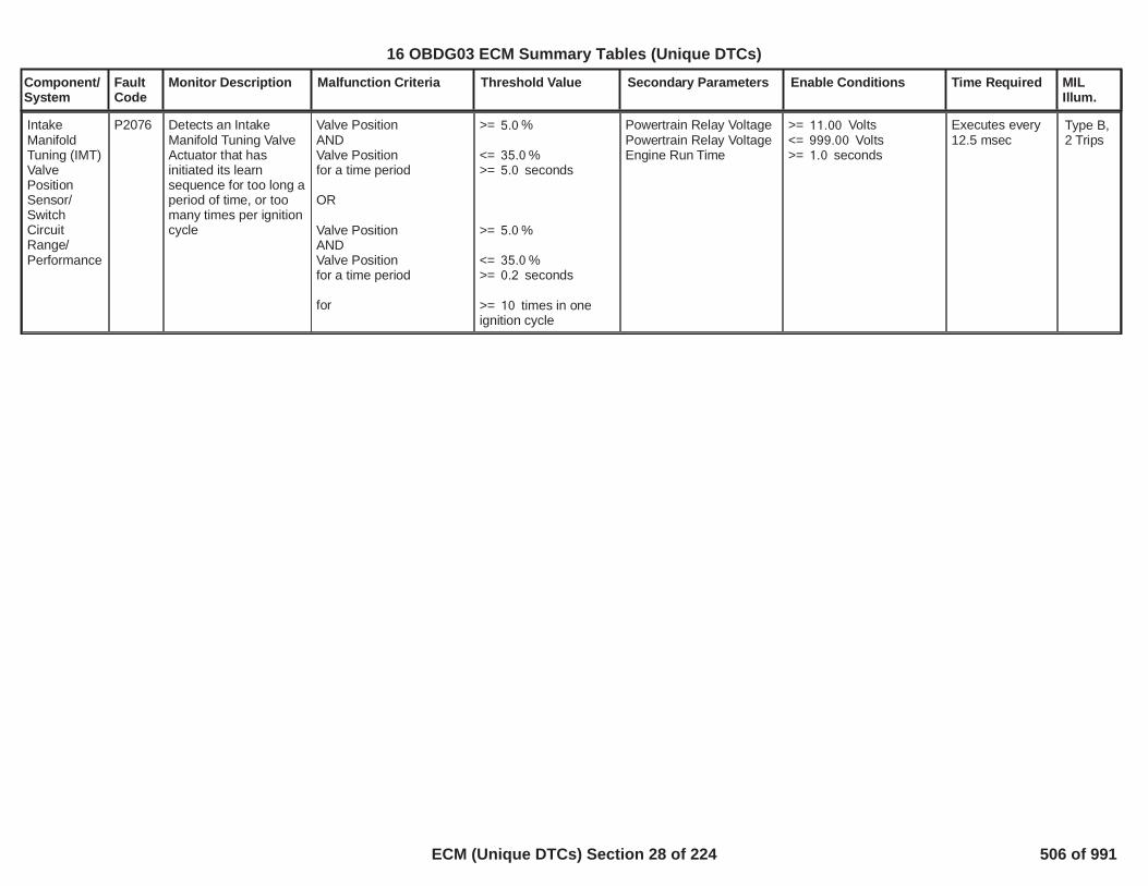
Component/System
FaultCode
Monitor Description Malfunction Criteria Threshold Value Secondary Parameters Enable Conditions Time Required MILIllum.
IntakeManifoldTuning (IMT)ValvePositionSensor/SwitchCircuitRange/Performance
P2076 Detects an IntakeManifold Tuning ValveActuator that hasinitiated its learnsequence for too long aperiod of time, or toomany times per ignitioncycle
Valve PositionANDValve Positionfor a time period
OR
Valve PositionANDValve Positionfor a time period
for
>= %5.0
<= %35.0>= seconds5.0
>= %5.0
<= %35.0>= seconds0.2
>= times in one10ignition cycle
Powertrain Relay VoltagePowertrain Relay VoltageEngine Run Time
>= Volts11.00<= Volts999.00>= seconds1.0
Executes every12.5 msec
Type B,2 Trips
28
16 OBDG03 ECM Summary Tables (Unique DTCs)
ECM (Unique DTCs) Section 28 of 224 506 of 991

Component/System
FaultCode
Monitor Description Malfunction Criteria Threshold Value Secondary Parameters Enable Conditions Time Required MILIllum.
IntakeManifoldTuning (IMT)ValvePositionSensor/SwitchCircuit Low
P2077 Detects a continuousopen or short to low inthe Intake ManifoldTuning Valve PositionSensor circuit
Valve Position >= %95.0 Continuous failures out320of samples400
1 sample every12.5 msec
Type B,2 Trips
29
16 OBDG03 ECM Summary Tables (Unique DTCs)
ECM (Unique DTCs) Section 29 of 224 507 of 991

Component/System
FaultCode
Monitor Description Malfunction Criteria Threshold Value Secondary Parameters Enable Conditions Time Required MILIllum.
IntakeManifoldTuning (IMT)ValvePositionSensor/SwitchCircuit High
P2078 Detects a continuousshort to high in theIntake Manifold TuningValve Position Sensorcircuit
Valve Position <= %5.0 Continuous failures out320of samples400
1 sample every12.5 msec
Type B,2 Trips
30
16 OBDG03 ECM Summary Tables (Unique DTCs)
ECM (Unique DTCs) Section 30 of 224 508 of 991

Component/System
FaultCode
Monitor Description Malfunction Criteria Threshold Value Secondary Parameters Enable Conditions Time Required MILIllum.
BarometricPressure(BARO)SensorCircuit Low(non-boostedapplications)
P2228 Detects a continuousshort to low or open ineither the signal circuitor the BARO sensor.
BARO Voltage < % of 5 Volt40.0Range( Volts = kPa)2.0 50.9
failures out320of samples400
1 sample every12.5 msec
Type B,2 Trips
31
16 OBDG03 ECM Summary Tables (Unique DTCs)
ECM (Unique DTCs) Section 31 of 224 509 of 991

Component/System
FaultCode
Monitor Description Malfunction Criteria Threshold Value Secondary Parameters Enable Conditions Time Required MILIllum.
BarometricPressure(BARO)SensorCircuit High(non-boostedapplications)
P2229 Detects an opensensor ground orcontinuous short tohigh in either the signalcircuit or the BAROsensor.
BARO Voltage > % of 5 Volt90.0Range( Volts =4.5 115.0kPa)
failures out320of samples400
1 sample every12.5 msec
Type B,2 Trips
32
16 OBDG03 ECM Summary Tables (Unique DTCs)
ECM (Unique DTCs) Section 32 of 224 510 of 991
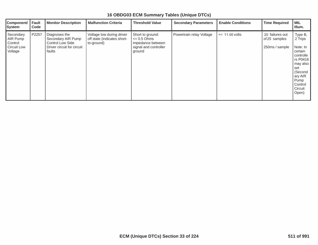
Component/System
FaultCode
Monitor Description Malfunction Criteria Threshold Value Secondary Parameters Enable Conditions Time Required MILIllum.
SecondaryAIR PumpControlCircuit LowVoltage
P2257 Diagnoses theSecondary AIR PumpControl Low SideDriver circuit for circuitfaults
Voltage low during driveroff state (indicates short-to-ground)
Short to ground:<= 0.5 Ohmsimpedance betweensignal and controllerground
Powertrain relay Voltage >= volts11.00 failures out20of samples25
250ms / sample
Type B,2 Trips
Note: Incertaincontrollers P0418may alsoset(Secondary AIRPumpControlCircuitOpen)
33
16 OBDG03 ECM Summary Tables (Unique DTCs)
ECM (Unique DTCs) Section 33 of 224 511 of 991

Component/System
FaultCode
Monitor Description Malfunction Criteria Threshold Value Secondary Parameters Enable Conditions Time Required MILIllum.
SecondaryAIR PumpControlCircuit HighVoltage
P2258 Diagnoses theSecondary AIR PumpControl Low SideDriver circuit for circuitfaults
Voltage high during driveron state (indicates short-to-power)
Short to power:<= 0.5 Ohmsimpedance betweensignal and controllerpower
Powertrain relay Voltage >= volts11.00 failures out20of samples25
250ms / sample
Type B,2 Trips
34
16 OBDG03 ECM Summary Tables (Unique DTCs)
ECM (Unique DTCs) Section 34 of 224 512 of 991

Component/System
FaultCode
Monitor Description Malfunction Criteria Threshold Value Secondary Parameters Enable Conditions Time Required MILIllum.
SecondaryAIR SystemPressureSensorCircuit Bank1
P2430 This DTC detects astuck in range pressuresensor signal when theAIR pump iscommanded on.
Average Pressure Error
ANDSignal Variation
< kPa0.50
< kPa1.00
BAROInlet Air TempCoolant TempEngine off timeSystem VoltageMAP notEngine SpeedMAF not
No active DTCs:
> kPa60> deg C-10.0> deg C <-10.0 80.0> seconds3,600.0> Volts <10.0 32.0< kPa for sec20 2.0< RPM5,000> gm/s for sec50 3.0
AIRValveControlCircuit FAAIRPumpControlCircuitFAP2432P2437P2433P2438P0606
Stuck in rangecumulative time> seconds5.0
Frequency: Onceper trip when SAIpump iscommanded On
Type B,2 Trips
35
16 OBDG03 ECM Summary Tables (Unique DTCs)
ECM (Unique DTCs) Section 35 of 224 513 of 991

Component/System
FaultCode
Monitor Description Malfunction Criteria Threshold Value Secondary Parameters Enable Conditions Time Required MILIllum.
SecondaryAIR SystemPressureSensorPerformanceBank 1
P2431 This DTC detects askewed pressuresensor signal via acomparison of the AIRpressure sensor signaland estimated BARO,as well as anevaluation of the qualityof the comparison.
Difference between AIRpressure sensor andBARO (PumpCommanded Off)or
OR
Difference between AIRpressure sensor andBARO (PumpCommanded On)
> kPa15.0
< kPa-15.0
> kPa50.0
BAROInlet Air TempCoolant TempEngine off timeSystem VoltageMAP notEngine SpeedMAF not
Transfer Case not in 4WDLowRun/crank active
No active DTCs:
> kPa60> deg C-10.0> deg C <-10.0 80.0> seconds3,600.0> Volts <10.0 32.0< kPa for sec20 2.0< RPM5,000> gm/s for sec50 3.0
AIRValveControlCircuit FAAIRPumpControlCircuitFAP2432P2437P2433P2438MAF_SensorFAEngineMisfireDetected_FAP0606
Skewed sensorcumulative testweight > 30.0seconds
Continuous6.25ms loop
Skewed sensorcumulatative testweight is basedon distance fromthe last Baroupdate. SeeP2431_P2436Baro SkewedSensor WeightFactortable.
Type B,2 Trips
36
16 OBDG03 ECM Summary Tables (Unique DTCs)
ECM (Unique DTCs) Section 36 of 224 514 of 991
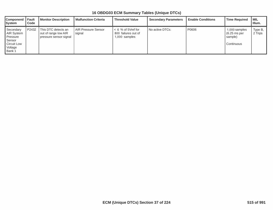
Component/System
FaultCode
Monitor Description Malfunction Criteria Threshold Value Secondary Parameters Enable Conditions Time Required MILIllum.
SecondaryAIR SystemPressureSensorCircuit LowVoltageBank 1
P2432 This DTC detects anout of range low AIRpressure sensor signal
AIR Pressure Sensorsignal
< % of 5Vref for6failures out of800
samples1,000
No active DTCs: P0606 samples1,000(6.25 ms persample)
Continuous
Type B,2 Trips
37
16 OBDG03 ECM Summary Tables (Unique DTCs)
ECM (Unique DTCs) Section 37 of 224 515 of 991

Component/System
FaultCode
Monitor Description Malfunction Criteria Threshold Value Secondary Parameters Enable Conditions Time Required MILIllum.
SecondaryAIR SystemPressureSensorCircuit HiVoltageBank 1
P2433 This DTC detects anout of range high AIRpressure sensor signal
AIR Pressure Sensorsignal
> % of 5Vref for94failures out of800
samples1,000
No active DTCs: P0606 samples1,000(6.25 ms persample)
Continuous
Type B,2 Trips
38
16 OBDG03 ECM Summary Tables (Unique DTCs)
ECM (Unique DTCs) Section 38 of 224 516 of 991

Component/System
FaultCode
Monitor Description Malfunction Criteria Threshold Value Secondary Parameters Enable Conditions Time Required MILIllum.
SecondaryAIR SystemShut-offValve StuckOpen (forsingle valvesystems)
P2440 This DTC detects if oneor both of the AIRsystem control valvesis stuck openThis testis run during Phase 2(Pump commandedOn, valve commandedclosed)
Average Pressure Error
or
<P2440 Bank 1 ValvePressure Error
table
> kPa32
BAROInlet Air TempCoolant TempEngine off timeSystem VoltageMAP notEngine SpeedMAF notStability Time
AIR diagnostic Phase 1passed
No active DTCs:
> kPa60> deg C-10.0> deg C <-10.0 80.0> seconds3,600.0> Volts <10.0 32.0< kPa for sec20 2.0< RPM5,000> gm/s for sec50 3.0> seconds0.5
AIRSystemPressureSensor FAAIRValveControlCircuit FAAIRPumpControlCircuitFAMAF_SensorFAAmbientAirDefaultIAT_SensorFAECT_Sensor_FAEngineMisfireDetected_FACatalystSysEfficiencyLoB1_FACatalystSysEfficiencyLoB2_FAP0606IgnitionOutputDriver_FAFuelInjectorCircuit_FA
Phase 2Conditional testweight > sec1.5
Frequency:Once per tripwhen AIR pumpcommanded On
Conditional testweight iscalculated bymultiplying thefollowingFactors:
,
P2440 Phase 2Baro TestWeight Factor
,
P2440 Phase 2MAF TestWeight Factor
,
P2440 Phase 2System VoltTest WeightFactorP2440 Phase 2Amb Temp TestWeight Factor(see SupportingTables)
Type B,2 Trips
39
16 OBDG03 ECM Summary Tables (Unique DTCs)
ECM (Unique DTCs) Section 39 of 224 517 of 991

Component/System
FaultCode
Monitor Description Malfunction Criteria Threshold Value Secondary Parameters Enable Conditions Time Required MILIllum.
SecondaryAIR SystemPump StuckOn (forsingle valvesystems)
P2444 This DTC detects if theSAI pump is stuck On.This test is run duringPhase 3 (Pumpcommanded Off, valvecommanded closed)
Average Pressure Error
or
>P2444 Bank 1 PumpPressure Error
table
< kPa-32
BAROInlet Air TempCoolant TempEngine off timeSystem VoltageMAP notEngine SpeedMAF notStability Time
AIR diagnostic Phase 1passedAIR diagnostic Phase 2passed
No active DTCs:
> kPa60> deg C-10.0> deg C <-10.0 80.0> seconds3,600.0> Volts <10.0 32.0< kPa for > sec20 2.0< RPM5,000> gm/s for > sec50 3.0> seconds4.0
Phase 3 cumulatative testweight is based on thedistance from the lastBaro update. SeeP2431_P2436 BaroSkewed Sensor WeightFactortable.
AIRSystemPressureSensor FAAIRValveControlCircuit FAAIRPumpControlCircuitFAMAF_SensorFAAmbientAirDefaultIAT_SensorFAECT_Sensor_FAEngineMisfireDetected_FACatalystSysEfficiencyLoB1_FACatalystSysEfficiencyLoB2_FAP0606IgnitionOutputDriver_FAFuelInjectorCircuit_FA
Phase 3Cumlatative testweight > sec.2.0
Frequency: Onceper trip when AIRpump iscommanded On
Type A,1 Trips
40
16 OBDG03 ECM Summary Tables (Unique DTCs)
ECM (Unique DTCs) Section 40 of 224 518 of 991

Component/System
FaultCode
Monitor Description Malfunction Criteria Threshold Value Secondary Parameters Enable Conditions Time Required MILIllum.
Brake PedalPositionSensorCircuitIntermittent/Erratic
P057E detects noisy / erraticouput for brake pedalposition sensor
If x of y samples areobserved above failurethreshold, default brakepedal position to zeropercent and set DTC
25.00 Brake Pedal PositionSensor CircuitIntermittent / ErraticDiagnostic Enable
1.00 /10.00
counts16.00
MIL:Type A,1 Trips
1
16 OBDG03 ECM Summary Tables (Unique DTCs)
ECM (Unique DTCs) Section 41 of 224 519 of 991

Component/System
FaultCode
Monitor Description Malfunction Criteria Threshold Value Secondary Parameters Enable Conditions Time Required MILIllum.
CruiseControlMulti-FunctionInput BCircuit
P0589 Detect when cruisecontrol multi-functionswitch circuit B(analog) voltage is inan illegal range
Cruise Control analogcircuit B voltage must bein an "illegal range" or"between ranges" forgreater than a calibratableperiod of time for cruiseswitch states that arereceived over serial data
CAN cruise switchdiagnostic enable in ECM
1.00 fail continuouslyfor greater than0.500seconds
Type C,No SVS,specialtype C
2
16 OBDG03 ECM Summary Tables (Unique DTCs)
ECM (Unique DTCs) Section 42 of 224 520 of 991

Component/System
FaultCode
Monitor Description Malfunction Criteria Threshold Value Secondary Parameters Enable Conditions Time Required MILIllum.
CruiseControlMulti-FunctionInput BCircuit Low
P0592 detects short to groundfailure for cruise multi-function switch circuit B
Cruise Control analogcircuit B voltage must bein an "Open Short ToGround" for greater than acalibratable period of timefor cruise switch statesthat are received overserial data
CAN cruise switchdiagnostic enable in ECM
1.00 fail continuouslyfor greater than2.00seconds
Type C,No SVS,specialtype C
3
16 OBDG03 ECM Summary Tables (Unique DTCs)
ECM (Unique DTCs) Section 43 of 224 521 of 991

Component/System
FaultCode
Monitor Description Malfunction Criteria Threshold Value Secondary Parameters Enable Conditions Time Required MILIllum.
CruiseControlMulti-FunctionInput BCircuit High
P0593 Cruise Control analogcircuit B voltage must bein an "Short To Power" forgreater than a calibratableperiod of time for cruiseswitch states that arereceived over serial data
CAN cruise switchdiagnostic enable in ECM
1.00 fail continuouslyfor greater than2.00seconds
Type C,No SVS, specialtype C
4
16 OBDG03 ECM Summary Tables (Unique DTCs)
ECM (Unique DTCs) Section 44 of 224 522 of 991

Component/System
FaultCode
Monitor Description Malfunction Criteria Threshold Value Secondary Parameters Enable Conditions Time Required MILIllum.
Fuel PumpControlModule(FPCM)RequestedMILIllumination
P069E Monitors the FPCM MILrequest line todetermine when theFPCM has detected aMIL illuminating fault.
Fuel Pump ControlModule Emissions-Related DTC set
Time since power-up 3seconds
Continuous Type A,No MIL
5
16 OBDG03 ECM Summary Tables (Unique DTCs)
ECM (Unique DTCs) Section 45 of 224 523 of 991

Component/System
FaultCode
Monitor Description Malfunction Criteria Threshold Value Secondary Parameters Enable Conditions Time Required MILIllum.
Stop-StartCapacitorTemperatureSensorCircuit High
P105B Indicates that thecapacitor temperatureis out of range - low
Stop-Start capacitortemperature value < deg C-60.0
No active DTCs
Diagnostic reporting isenabled when thefollowing two steps finish:
(A) LIN bus wake up
Then,
(B) ESCM wake up delay
Afterwards, this diagnosticruns continuously.
U135C, U1347, P1066
= TRUE
> sec0.50
failure out of10samples14
500ms cycletime
continuous
Type B,2 Trips
6
16 OBDG03 ECM Summary Tables (Unique DTCs)
ECM (Unique DTCs) Section 46 of 224 524 of 991
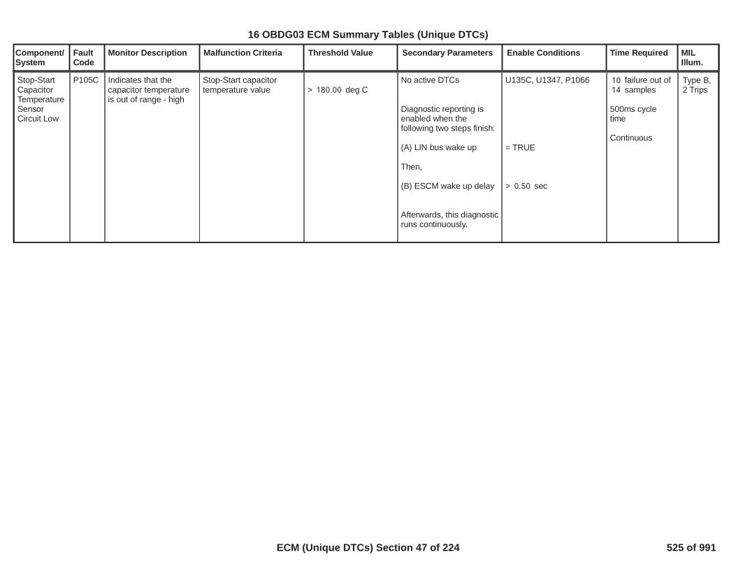
Component/System
FaultCode
Monitor Description Malfunction Criteria Threshold Value Secondary Parameters Enable Conditions Time Required MILIllum.
Stop-StartCapacitorTemperatureSensorCircuit Low
P105C Indicates that thecapacitor temperatureis out of range - high
Stop-Start capacitortemperature value > deg C180.00
No active DTCs
Diagnostic reporting isenabled when thefollowing two steps finish:
(A) LIN bus wake up
Then,
(B) ESCM wake up delay
Afterwards, this diagnosticruns continuously.
U135C, U1347, P1066
= TRUE
> sec0.50
failure out of10samples14
500ms cycletime
Continuous
Type B,2 Trips
7
16 OBDG03 ECM Summary Tables (Unique DTCs)
ECM (Unique DTCs) Section 47 of 224 525 of 991

Component/System
FaultCode
Monitor Description Malfunction Criteria Threshold Value Secondary Parameters Enable Conditions Time Required MILIllum.
Stop-StartCapacitorTemperatureSensor NotPlausible
P105D Indicates that thecapacitor temperatureis not rational/plausible
Absolute value oftemperature differencebetween capacitor andDCDC converter
AND
Absolute value oftemperature differencebetween capacitor andcapacitor switch (K2)
> deg C15.00
> deg C15.00
No active DTCs
Diagnostic reporting isenabled when thefollowing three stepsfinish:
(A) ECM off time
Then,
(B) LIN bus wake up
Then,
(C) ESCM wake up delay
Note: This is not acontinuous diagnositc. Itruns once at LIN buswake up, after ECM offtime is large enough.
U135C, U1347, P1066
> sec28,800
= TRUE
> sec0.50
Wake up testonly.
Fault is set atfirst detection.
Type B,2 Trips
8
16 OBDG03 ECM Summary Tables (Unique DTCs)
ECM (Unique DTCs) Section 48 of 224 526 of 991

Component/System
FaultCode
Monitor Description Malfunction Criteria Threshold Value Secondary Parameters Enable Conditions Time Required MILIllum.
Stop-StartCapacitorControlModuleDCDCConverterTemperatureSensorCircuit High
P105E Indicates that theDCDC convertertemperature is out ofrange - low
DCDC convertertemperature < deg C-50.00
No active DTCs
Diagnostic reporting isenabled when thefollowing two steps finish:
(A) LIN bus wake up
Then,
(B) ESCM wake up delay
Afterwards, thisdiagnostic runscontinuously.
U135C, U1347, P1066
= TRUE
> sec0.50
failure out of10samples14
500ms cycletime
continuous
Type B,2 Trips
9
16 OBDG03 ECM Summary Tables (Unique DTCs)
ECM (Unique DTCs) Section 49 of 224 527 of 991

Component/System
FaultCode
Monitor Description Malfunction Criteria Threshold Value Secondary Parameters Enable Conditions Time Required MILIllum.
Stop-StartCapacitorControlModule DC/DCConverterTemperatureSensorCircuit Low
P105F Indicates that theDCDC convertertemperature is out ofrange - high
DCDC convertertemperature > deg C160.00
No active DTCs
Diagnostic reporting isenabled when thefollowing two steps finish:
(A) LIN bus wake up
Then,
(B) ESCM wake up delay
Afterwards, thisdiagnostic runscontinuously.
U135C, U1347, P1066
= TRUE
> sec0.50
failure out of10samples14
500ms cycletime
continuous
Type B,2 Trips
10
16 OBDG03 ECM Summary Tables (Unique DTCs)
ECM (Unique DTCs) Section 50 of 224 528 of 991

Component/System
FaultCode
Monitor Description Malfunction Criteria Threshold Value Secondary Parameters Enable Conditions Time Required MILIllum.
Stop-StartCapacitorControlModule DC/DCConverterTemperatureSensor NotPlausible
P1060 Indicates that theDCDC convertertemperature is notrational/plausible
The absolute value oftemperature differencebetween DCDC converterand capacitor.
AND
The absolute value oftemperature differencebetween DCDC converterand capacitor switch (K2).
> deg C15.00
> deg C15.00
No active DTCs
Diagnostic reporting isenabled when thefollowing three stepsfinish:
(A) ECM off time
Then,
(B) LIN bus wake up
Then,
(C) ESCM wake up delay
Note: This is not acontinuous diagnositc. Itruns once at LIN buswake up, after ECM offtime is large enough.
U135C, U1347, P1066
> sec28,800
= TRUE
> sec0.50
Wake up testonly.
Fault is set atfirst detection.
Type B,2 Trips
11
16 OBDG03 ECM Summary Tables (Unique DTCs)
ECM (Unique DTCs) Section 51 of 224 529 of 991

Component/System
FaultCode
Monitor Description Malfunction Criteria Threshold Value Secondary Parameters Enable Conditions Time Required MILIllum.
Stop-StartCapacitorSecondarySwitchTemperatureSensorCircuit High
P1061 Indicates that thecapacitor switch (K2)temperature is out ofrange - low
Capacitor switch (K2)temperature < deg C-50.00
No active DTCs
Diagnostic reporting isenabled when thefollowing two steps finish:
(A) LIN bus wake up
Then,(B) ESCM wake up delay
Afterwards, thisdiagnostic runscontinuously.
U135C, U1347, P1066
= TRUE
> sec0.50
failure out of10samples14
500ms cycletime
continuous
Type B,2 Trips
12
16 OBDG03 ECM Summary Tables (Unique DTCs)
ECM (Unique DTCs) Section 52 of 224 530 of 991

Component/System
FaultCode
Monitor Description Malfunction Criteria Threshold Value Secondary Parameters Enable Conditions Time Required MILIllum.
Stop-StartCapacitorSecondarySwitchTemperatureSensorCircuit Low
P1062 Indicates that thecapacitor switch (K2)temperature is out ofrange - high
The capacitor switch (K2)temperature > deg C160.00
No active DTCs
Diagnostic reporting isenabled when thefollowing two steps finish:
(A) LIN bus wake up
Then,(B) ESCM wake up delay
Afterwards, thisdiagnostic runscontinuously.
U135C, U1347, P1066
= TRUE
> sec0.50
failure counts10out of 14samples
500ms cycletime
continuous
Type B,2 Trips
13
16 OBDG03 ECM Summary Tables (Unique DTCs)
ECM (Unique DTCs) Section 53 of 224 531 of 991

Component/System
FaultCode
Monitor Description Malfunction Criteria Threshold Value Secondary Parameters Enable Conditions Time Required MILIllum.
Stop-StartCapacitorSecondarySwitchTemperatureSensor NotPlausible
P1063 Indicates that theCapacitor Switch (K2)Temperature SensorNot Rational/Plausible
The absolute value oftemperature differencebetween the capacitorswitch (K2) and thecapacitor.
AND
The absolute value oftempeature differencebetween the capacitorswitch (K2) and DCDCconverter.
> deg C15.00
> deg C15.00
No active DTCs
Diagnostic reporting isenabled when thefollowing three stepsfinish:
(A) ECM off time
Then,
(B) LIN bus wake up
Then,
(C) ESCM wake up delay
Note: This is not acontinuous diagnositc. Itruns once at LIN buswake up, after ECM offtime is large enough.
U135C, U1347, P1066
> sec28,800
= TRUE
> sec0.50
Wake up testonly.
Fault is set atfirst detection.
Type B,2 Trips
14
16 OBDG03 ECM Summary Tables (Unique DTCs)
ECM (Unique DTCs) Section 54 of 224 532 of 991

Component/System
FaultCode
Monitor Description Malfunction Criteria Threshold Value Secondary Parameters Enable Conditions Time Required MILIllum.
SystemVoltage LowDuring StartAssist
P1064 This DTC indicates thatthe system voltage islow during a start whenassist is expected
The diagnostic method isselected from method (A)or (B) below.
The two methods are:Method (A) =CeUCCD_e_UseGrdORMethod (B) =CeUCCD_e_UseDeltaVlt
The method used on thisapplication is
*********************
Method (A) -The average systemvoltage during an assistedauto start is
Method (B) -The average systemvoltage delta during anassisted auto start is
=CeUCCD_e_UseDeltaVlt*********************
<= V9.00
> V3.00
No active DTCs
Low Fuel Condition DiagFuel Level Data Fault
(ECTOROBD Coolant EnableCriteria
Auto start is commandedfrom an auto stop state
U135C, U1347, P105B,P105C, P105D, P105E,P105F, P1060, P1061,P1062, P1063, P1066,P1067, P1068, P1069,P106A, P106B, P106C,P106E, P106F, P1070,P1071, P1072, P1073,P1074, P1075, P1076,P1077, P1078, P1079,P107A, P107B, P107C,P107E, P107F, P1080,P1081, P108A, P108B,P108C, P108D, P108E,P108F, P1090, P1091,ECT_Sensor_Ckt_FAECT_Sensor_Perf_FA
= FALSE= FALSE
> Deg C30.00
= TRUE)
= TRUE
Diagnostic runswhen auto startis commanedfrom an autostop state.
Minimum autostop time > 1.00sec
The test resultaverage iscalculated usingdata from auto3start events.
Type B,2 Trips
15
16 OBDG03 ECM Summary Tables (Unique DTCs)
ECM (Unique DTCs) Section 55 of 224 533 of 991

Component/System
FaultCode
Monitor Description Malfunction Criteria Threshold Value Secondary Parameters Enable Conditions Time Required MILIllum.
Stop-StartCapacitorControlModuleChargingCurrentPerformance
P1065 This DTC indicates thatthe capacitor voltage isnot charged to theexpected voltage targetwhile the engine isrunning
The diagnostic measuresthe capacitor voltage andcompares it to acalibration value that isspecific to the deratinglevel .
*****************************Derating level 0Capacitor temperature
Capacitor voltagethreshold to arm the autostart
*****************************Derating level 1Capacitor temperature
Capacitor voltagethreshold
*****************************Derating level 2Capacitor temperature
Capacitor voltagethreshold
*****************************
deg C <-40.0capacitor temperature< deg C55.0
<= Refer toP1065_UCAP_Arm_Autostart_Thresh_Derating_Zeroin the SupportingTables tab.
deg C =<55.0capacitor temperature< deg C61.0
<= V2.70
deg C =<61.0capacitor temperature< deg C73.0
<= V2.20
No active DTCs
(ECTOROBD Coolant EnableCriteria
Engine run
No change of thecapacitor derating levelduring the test
Capacitor temperature
Delay period beforeaccumulating fails (allowstime for caps to charge)
U135C, U1347, P105B,P105C, P105D, P105E,P105F, P1060, P1061,P1062, P1063, P1066,P1067, P1068, P1069,P106A, P106B, P106C,P106E, P106F, P1070,P1071, P1072, P1073,P1074, P1075, P1076,P1077, P1078, P1079,P107A, P107B, P107C,P107E, P107F, P1080,P1081, P108A, P108B,P108C, P108D, P108E,P108F, P1090, P1091,ECT_Sensor_Ckt_FAECT_Sensor_Perf_FA
> Deg C30.00
= TRUE)
= TRUE
= TRUE
deg C < capacitor-40.0temperature < deg C73.0
= seconds10.0
failures out320of samples400
500ms cycletime
Continuouslyruns whenenableconditions aremet.
Type B,2 Trips
16
16 OBDG03 ECM Summary Tables (Unique DTCs)
ECM (Unique DTCs) Section 56 of 224 534 of 991

Component/System
FaultCode
Monitor Description Malfunction Criteria Threshold Value Secondary Parameters Enable Conditions Time Required MILIllum.
Stop-StartCapacitorControlModuleStatusMessageCounterIncorrect
P1066 This DTC indicates thatan error is detected onthe Alive RollingCounter (ARC) in theLIN frame data
If one or more of thefollowing Alive RollingCounter (ARC) errors inLIN frames from thecapacitor control modulehas matured, P1066 isset:
ARC error counts forUCAP Current Statusframe
OR
ARC error counts forUCAP TemperatureStatus frame
OR
ARC error counts forUCAP Temperature Faultframe
OR
ARC error counts forUCAP Part Number frame
>= failures10ouf of samples10
>= failures10out of samples10
>= failures10out of samles10
>= failures10out of samples10
Diagnostic reporting isenabled when thefollowing conditions aremet:
(A) LIN bus wake up
Then,
(B) Diagnostic delay
(C) Powertrain RelayVoltage
(D) Run/Crank IgnitionVoltage
= TRUE
>= sec3.00
>= V11.00
>= V11.00
Executes in 12.5ms loop
Continuously
Type A,1 Trips
17
16 OBDG03 ECM Summary Tables (Unique DTCs)
ECM (Unique DTCs) Section 57 of 224 535 of 991

Component/System
FaultCode
Monitor Description Malfunction Criteria Threshold Value Secondary Parameters Enable Conditions Time Required MILIllum.
The ground switch (K1)current is out of range < -1330 amps
OR> 1330 amps
No active DTCs
Diagnostic reporting isenabled when thefollowing three stepsfinish:
(A) LIN bus wake up
Then,
(B) ESCM wake up delay
Then,
(C) Fault maturity delayexpires, and the next validLIN frame has beenreceived; or wheneverfault state from ESCMchanges its value
Afterwards, thisdiagnostic runscontinuously.
U135C, U1347, P1066
= TRUE
> sec0.50
> sec0.51
Test cycle time is5ms
Error countincreases by 10if an error isdetected, up to amaximum valueof 200.
Error countdecreases by 1 ifno error isdetected,minimum value0.
Fault is set whenerror count = 200(100ms faultmaturity)
Fault is removedwhen error count= 0.(1 sec healingtime)
Stop-StartCapacitorControlModulePerformance
P1067 This DTC Indicates oneor more of the followingfaults have occured:Case 1: The groundswitch (K1) currentsensor is faulty.Case 2: The capacitorswitch (K2) currentsensor is faulty.Case 3: The onboardvoltages indicate afaulty voltage regulator.Case 4: The analoginput circuits are faulty.Case 5: The capacitorvoltage sensor is stuckat maximum.
Type B,2 Trips
The ground switch (K2)current is out of range < -1330 amps
OR> 1330 amps
No active DTCs
Diagnostic reporting isenabled when thefollowing three stepsfinish:
(A) LIN bus wake up
Then,
U135C, U1347, P1066
= TRUE
Test cycle time is5ms
Error countincreases by 10if an error isdetected, up to amaximum valueof 200.
Error count
18
16 OBDG03 ECM Summary Tables (Unique DTCs)
ECM (Unique DTCs) Section 58 of 224 536 of 991

Component/System
FaultCode
Monitor Description Malfunction Criteria Threshold Value Secondary Parameters Enable Conditions Time Required MILIllum.
(B) ESCM wake up delay
Then,
(C) Fault maturity delayexpires, and the next validLIN frame has beenreceived; or wheneverfault state from ESCMchanges its value
Afterwards, thisdiagnostic runscontinuously.
> sec0.50
> sec0.51
decreases by 1 ifno error isdetected,minimum value0.
Fault is set whenerror count = 200(100ms faultmaturity)
Fault is removedwhen error count= 0.(1 sec healingtime)
Internal Power Supplies2.5 V Reference5.0 V Linear regulator
15.0 V Boost regulatorare not functional or out ofrange.
Correct range is:2.5 V +/- 0.1%5.0 V +/- 0.2 V
15.0 V +/- 1.0 V
No active DTCs
Diagnostic reporting isenabled when thefollowing three stepsfinish:
(A) LIN bus wake up
Then,
(B) ESCM wake up delay
Then,
(C) Fault maturity delayexpires, and the next validLIN frame has beenreceived; ; or wheneverfault state from ESCMchanges its value
U135C, U1347, P1066
= TRUE
> sec0.50
> sec0.51
Test cycle time is5ms
Error countincreases by 100if an error isdetected, up to amaximum valueof 200.
Error countdecreases by 1 ifno error isdetected,minimum value0.
Fault is set whenerror count = 200(10 ms faultmaturity)
Fault is removed
19
16 OBDG03 ECM Summary Tables (Unique DTCs)
ECM (Unique DTCs) Section 59 of 224 537 of 991

Component/System
FaultCode
Monitor Description Malfunction Criteria Threshold Value Secondary Parameters Enable Conditions Time Required MILIllum.
Afterwards, thisdiagnostic runscontinuously.
when error count= 0.(1 sec healingtime)
The analog input circuitsare faulty:
Measured 2.5V Referencevoltage of out of range,which is a indicator thatthe analog inputs to A/Dconverter are faulty
<2.23 VOR> 2.78 V
No active DTCs
Diagnostic reporting isenabled when thefollowing three stepsfinish:
(A) LIN bus wake up
Then,
(B) ESCM wake up delay
Then,
(C) Fault maturity delayexpires, and the next validLIN frame has beenreceived; or wheneverfault state from ESCMchanges its value
Afterwards, this diagnosticruns when the followingconditions are met:
Internal Power Supplies
DCDC
U135C, U1347, P1066
= TRUE
> sec0.50
> sec0.51
= OK
= Not active
Test cycle time is5ms
Error countincreases by 20if an error isdetected, up to amaximum valueof 200.
Error countdecreases by 1 ifno error isdetected,minimum value0.
Fault is set whenerror count = 200(50ms faultmaturity)
Fault is removedwhen error count= 0.(1 sec healingtime)
The measured capacitorvoltage >=5.86 V
No active DTCs
Diagnostic reporting isenabled when thefollowing three steps
U135C, U1347, P1066 Test cycle time is10ms
Error countincreases by 10if an error is
20
16 OBDG03 ECM Summary Tables (Unique DTCs)
ECM (Unique DTCs) Section 60 of 224 538 of 991

Component/System
FaultCode
Monitor Description Malfunction Criteria Threshold Value Secondary Parameters Enable Conditions Time Required MILIllum.
finish:
(A) LIN bus wake up
Then,
(B) ESCM wake up delay
Then,
(C) Fault maturity delayexpires, and the next validLIN frame has beenreceived; or wheneverfault state from ESCMchanges its value
Afterwards, thisdiagnostic runscontinuously.
= TRUE
> sec0.50
> sec0.51
detected, up to amaximum valueof 100.
Error countdecreases by 1 ifno error isdetected,minimum value0.
Fault is set whenerror count = 100(100ms faultmaturity)
Fault is removedwhen error count= 0.(1 sec healingtime)
21
16 OBDG03 ECM Summary Tables (Unique DTCs)
ECM (Unique DTCs) Section 61 of 224 539 of 991

Component/System
FaultCode
Monitor Description Malfunction Criteria Threshold Value Secondary Parameters Enable Conditions Time Required MILIllum.
Stop-StartCapacitorDeteriorated
P1068 This DTC Indicates theend of life of thecapacitor.
Capacitance
OR
Equivalent serialresistance (ESR)
OR
Number of consecutivecycles in which one of thecapacitor cells has avoltage 0.6V lower thanthe other.
< 480 Farads
> 3.6 milliion Ohm
= 10 times
No active DTCs
Diagnostic reporting isenabled when thefollowing three stepsfinish:
(A) LIN bus wake up
Then,
(B) ESCM wake up delay
Then,
(C) Fault maturity delayexpires, and the next validLIN frame has beenreceived; or wheneverfault state from ESCMchanges its value
Note: This is notcontinuous diagnostic.
U135C, U1347, P1066
= TRUE
> sec0.50
> sec0.10
The capacitanceand ESR arecalculated duringstate of healthdetermination.Fault is set afterfirst detection.
Cell voltagedifference iscalculated afterESCM wake up.Fault is set after10 consecutivedetections.
This is apersistent faultthat can only beremoved byservice.
Type B,2 Trips
22
16 OBDG03 ECM Summary Tables (Unique DTCs)
ECM (Unique DTCs) Section 62 of 224 540 of 991

Component/System
FaultCode
Monitor Description Malfunction Criteria Threshold Value Secondary Parameters Enable Conditions Time Required MILIllum.
Stop-StartCapacitorVoltage High
P1069 This DTC indicates thatthe capacitor is overvoltage.
capacitor voltage > 5.8 V No active DTCs
Diagnostic reporting isenabled when thefollowing three stepsfinish:
(A) LIN bus wake up
Then,
(B) ESCM wake up delay
Then,
(C) Fault maturity delayexpires, and the next validLIN frame has beenreceived; or wheneverfault state from ESCMchanges its value
Afterwards, thisdiagnostic runscontinuously.
U135C, U1347, P1066
= TRUE
> sec0.50
> sec0.51
Test cycle time10ms
Error countincreases by 2 ifan error isdetected, up to amaximum valueof 100.
Error countdecreases by 1 ifno error isdetected,minimum value0.
Fault is set whenerror count = 100(500ms faultmaturity)
Fault is removedwhen error count= 0.(1 sec healingtime)
Type B,2 Trips
23
16 OBDG03 ECM Summary Tables (Unique DTCs)
ECM (Unique DTCs) Section 63 of 224 541 of 991

Component/System
FaultCode
Monitor Description Malfunction Criteria Threshold Value Secondary Parameters Enable Conditions Time Required MILIllum.
Stop-StartCapacitorControlModuleBatteryNegativeCircuit Driver"A" and "B"Stuck Open
P106A This DTC indicates thatthe ground swith (K1) isin a high impendancestate
Voltage drop across theground switch (K1) whencurrent > 550 amps
OR
Voltage drop across theground switch (K1) whencurrent > 550 amps
OR
Voltage drop across theground switch (K1) whencurrent <= 550 amps
OR
Voltage drop across theground switch (K1) whencurrent <= 550 amps
<-0.8 V
> 0.8 V
<-0.4 V
> 0.4V
No active DTCs
Diagnostic reporting isenabled when thefollowing three stepsfinish:
(A) LIN bus wake up
Then,(B) ESCM wake up delay
Then,(C) Fault maturity delayexpires, and the next validLIN frame has beenreceived; or wheneverfault state from ESCMchanges its value
Afterwards, thisdiagnostic runs when thefolloiwng conditions aremet:
Capacitor switch (K2)open
Ground switch (K1) closeis commanded
U135C, U1347, P1066
= TRUE
> sec0.50
> sec1.01
= TRUE
= TRUE
Test cycle time is10ms.
Error countincreases by 1 ifan error isdetected, up to amaximum of 100.
Error countdecreases by 1 ifno error isdetected, up to aminimum of 0.
Fault is set whenerror count =100.(1 sec faultmaturity)
Fault is removedwhen error count= 0.(1 sec healingtime)
Type A,1 Trips
24
16 OBDG03 ECM Summary Tables (Unique DTCs)
ECM (Unique DTCs) Section 64 of 224 542 of 991

Component/System
FaultCode
Monitor Description Malfunction Criteria Threshold Value Secondary Parameters Enable Conditions Time Required MILIllum.
Stop-StartCapacitorControlModuleGroundSwitches "A"or "B" StuckOpen
P106B Indicates that bothbanks of ground switch(K1) stuck open,cannot be closed
The ground switch (K1)flip-flop state.
Note: flip-flop is a basichardware componentused by software tocommand the switch toopen or close.
K1 driver voltage bank A
K1 driver voltage bank B
= stuck open
< 10.46 V
< 10.46 V
No active DTCs
Diagnostic reporting isenabled when thefollowing three stepsfinish:
(A) LIN bus wake up
Then,(B) ESCM wake up delay
Then,(C) Fault maturity delayexpires, and the next validLIN frame has beenreceived; or wheneverfault state from ESCMchanges its value
Afterwards, thisdiagnostic runs when thefollowing conditions aremet:
Ground switch iscommanded to close
U135C, U1347, P1066
= TRUE
> sec0.50
> sec0.05
= TRUE
Test cycle time is5ms.
Error countincreases by 20if an error isdetected, up to amaximum of 200.
Error countdecreases by 1 ifno error isdetected, up to aminimum of 0.
Fault is set whenerror count =200.(50ms faultmaturity)
Fault is removedwhen error count= 0.(1 sec healingtime)
Type B,2 Trips
25
16 OBDG03 ECM Summary Tables (Unique DTCs)
ECM (Unique DTCs) Section 65 of 224 543 of 991

Component/System
FaultCode
Monitor Description Malfunction Criteria Threshold Value Secondary Parameters Enable Conditions Time Required MILIllum.
Stop-StartCapacitorControlModuleChargePumpPerformance
P106D Indicates that thecharge pump (internalsafety supply voltage)does not work correctly.
The Internal safety supplyvoltage < 11.23 V
No active DTCs
Diagnostic reporting isenabled when thefollowing three stepsfinish:
(A) LIN bus wake up
Then,
(B) ESCM wake up delay
Then,
(C) Fault maturity delayexpires, and the next validLIN frame has beenreceived; or wheneverfault state from ESCMchanges its value
Afterwards, this diagnosticruns when the followingconditions are met, onceper drive cyle:
Capacitor voltage
Authorization to supportstart
U135C, U1347, P1066
= TRUE
> sec0.50
> sec1.10
> = 4.7V
= FALSE
Tested once perdriving cycle.
Needs enablingfrom SW: enable- wait 500ms -diagnose during500 ms - disable.
Test cycle time10 ms.
Error countincreases by 10if an errordetection occursup to a maximumof 100.
Error countdecreases by 1 ifno errordetection occursup to a minimumof 0.
Fault is set whenerror count =100.(100ms faultmaturity)
Fault can only beremoved in thenext wake up, orby LIN message.
Type B,2 Trips
26
16 OBDG03 ECM Summary Tables (Unique DTCs)
ECM (Unique DTCs) Section 66 of 224 544 of 991

Component/System
FaultCode
Monitor Description Malfunction Criteria Threshold Value Secondary Parameters Enable Conditions Time Required MILIllum.
Stop-StartCapacitorControlModuleState ofHealthUnkown
P106E This DTC indiates thatthe capacitor controlmodule state of healthhas not beendetermined
The ESCM state of health Has not beendetermined.
No active DTCs
Diagnostic reporting isenabled when thefollowing three stepsfinish:
(A) LIN bus wake up
Then,
(B) ESCM wake up delay
Then,
(C) Fault maturity delayexpires, and the next validLIN frame has beenreceived; or wheneverfault state from ESCMchanges its value
Note: This diagnostic runsonce per trip.
U135C, U1347, P1066
= TRUE
> Sec0.50
> sec10.00
Once per trip. Type B,2 Trips
27
16 OBDG03 ECM Summary Tables (Unique DTCs)
ECM (Unique DTCs) Section 67 of 224 545 of 991

Component/System
FaultCode
Monitor Description Malfunction Criteria Threshold Value Secondary Parameters Enable Conditions Time Required MILIllum.
Stop-StartCapacitorControlModule SelfTestIncomplete
P106F This DTC indicates thatthe self test of thecapacitor controlmodule has not beenperformed/completedfor multiple drivingcycles
Consecutive drivingcycles in which the self-test has not beenperformed/completed
>=11 drive cyclesNo active DTCs
Diagnostic reporting isenabled when thefollowing three stepsfinish:
(A) LIN bus wake up
Then,
(B) ESCM wake up delay
Then,
(C) Fault maturity delayexpires, and the next validLIN frame has beenreceived; or wheneverfault state from ESCMchanges its value
Note: This diagnostic runsat wake up usinginformation from previouspower down.
U135C, U1347, P1066
= TRUE
> sec0.50
> 0.03
Wake up testonly.
Fault is set afterfirst detection.
Fault can behealed if the selftest isperformed/completedwithout errors inthe last drivingcycle.
Type B,2 Trips
28
16 OBDG03 ECM Summary Tables (Unique DTCs)
ECM (Unique DTCs) Section 68 of 224 546 of 991

Component/System
FaultCode
Monitor Description Malfunction Criteria Threshold Value Secondary Parameters Enable Conditions Time Required MILIllum.
The capacitor voltageincrease rate after 5s ofcharge
<20 mV/sNo active DTCs
Diagnostic reporting isenabled when thefollowing three stepsfinish:
(A) LIN bus wake up
Then,
(B) ESCM wake up delay
Then,
(C) Fault maturity delayexpires, and the next validLIN frame has beenreceived; or wheneverfault state from ESCMchanges its value
Note:This diagnostic runs atevery charge when thefollowing conditions aremet:
DCDC charging
Capacitor voltage
U135C, U1347, P1066
= TRUE
> sec0.50
> sec5.00
= Active
> 0.5 V
First 5 secondsof each charge.
Fault is set afterfirst detetion.
Once Fault isset, it will persistin the samedriving cycle,and inhibit use ofDCDC.
Fault will beremoved in thenext wake up orby LIN message.
Stop-StartCapacitorOutputCircuit
P1070 This DTC indicates thatthe capacitor voltageoutput line isdisconnected or theDCDC is defective.
Type A,1 Trips
Capacitor output voltage
Capacitor (dual cell) midpoint voltage
< 0.5 V
> 0.8 V
No active DTCs
Diagnostic reporting isenabled when thefollowing three stepsfinish:
(A) LIN bus wake up
U135C, U1347, P1066
= TRUE
Test cycle time is5ms.
Error countincreases by 10if an errordetection occursup to a maximum
29
16 OBDG03 ECM Summary Tables (Unique DTCs)
ECM (Unique DTCs) Section 69 of 224 547 of 991

Component/System
FaultCode
Monitor Description Malfunction Criteria Threshold Value Secondary Parameters Enable Conditions Time Required MILIllum.
Then,
(B) ESCM wake up delay
Then,
(C) Fault maturity delayexpires, and the next validLIN frame has beenreceived; or wheneverfault state from ESCMchanges its value
Afterwards, this diagnosticruns continuously.
> sec0.50
> sec5.00
of 100.
Error countdecreases by 1 ifno errordetection occursup to a minimumof 0.
Fault is set whenerror count =100.(50ms faultmaturity)
Fault is removedwhen error count= 0.(1 sec healingtime)
The difference betweenthe following items (A)and (B)
(A) the sum of 3 Capacitorvoltage samples (sampledwith a 10ms reccurenceafter DCDC startscharging)
(B) the Capacitor voltagesampled before startingthe charge multiplied by 3
> 2.7 V No active DTCs
Diagnostic reporting isenabled when thefollowing three stepsfinish:
(A) LIN bus wake up
Then,(B) ESCM wake up delay
Then,(C) Fault maturity delayexpires, and the next validLIN frame has beenreceived; or wheneverfault state from ESCM
U135C, U1347, P1066
= TRUE
> sec0.50
> sec5.00
First 30ms everytime DCDCcharging isactive.
Fault is set afterfirst detetion.
Once Fault isset, it will persistin the samedriving cycle,and inhibit use ofDCDC.
Fault will beremoved in thenext wake up orby LIN message
30
16 OBDG03 ECM Summary Tables (Unique DTCs)
ECM (Unique DTCs) Section 70 of 224 548 of 991

Component/System
FaultCode
Monitor Description Malfunction Criteria Threshold Value Secondary Parameters Enable Conditions Time Required MILIllum.
changes its value
Note: This diagnostic runsat every charge, when thefollowing conditions met:
DCDC charging = Active
31
16 OBDG03 ECM Summary Tables (Unique DTCs)
ECM (Unique DTCs) Section 71 of 224 549 of 991

Component/System
FaultCode
Monitor Description Malfunction Criteria Threshold Value Secondary Parameters Enable Conditions Time Required MILIllum.
Stop-StartCapacitorControlModuleRead OnlyMemoryPerformance
P1071 This DTC indicates afailure of the ROM(flash programmemory)
The calculated checksumacross the ROM memorydoesn't match the storedchecksum computedduring the build of thesoftware.
checksum does notmatch.
No active DTCs
Diagnostic reporting isenabled when thefollowing three stepsfinish:
(A) LIN bus wake up
Then,
(B) ESCM wake up delay
Then,
(C) Fault maturity delayexpires, and the next validLIN frame has beenreceived; or wheneverfault state from ESCMchanges its value
Afterwards, this diagnosticruns continuously.
U135C, U1347, P1066
= TRUE
> sec0.50
sec0.01
10ms cycle timeto scan a portionof ROM.
The wholememory isscanned in lessthan 2.6seconds.
If fault isdetected,perform a resetup to apredefinednumber of times(5 times).
if this numberhas expired go toa Fail Safe Statethat can only beleft by ECUpowerdown
Note: in Fail SafeState, LINcommunicationis on, K1 isclosed, DCDC isoff.
Fault can only beremoved in nextwake up or byLIN message.
Type B,2 Trips
32
16 OBDG03 ECM Summary Tables (Unique DTCs)
ECM (Unique DTCs) Section 72 of 224 550 of 991

Component/System
FaultCode
Monitor Description Malfunction Criteria Threshold Value Secondary Parameters Enable Conditions Time Required MILIllum.
Stop-StartCapacitorControlModuleRandomAccessMemoryPerformance
P1072 This DTC indicates afailure of the RAM.
An error is detected whiletesting the RAM.
RAM memory cell isstuck at high or low
No active DTCs
Diagnostic reporting isenabled when thefollowing three stepsfinish:
(A) LIN bus wake up
Then,
(B) ESCM wake up delay
Then,
(C) Fault maturity delayexpires, and the next validLIN frame has beenreceived. or wheneverfault state from ESCMchanges its value
Afterwards, this diagnosticruns continuously.
U135C, U1347, P1066
= TRUE
> sec0.50
> Sec0.01
10ms cycle timeto scan a portionof RAM.
The wholememory isscanned in lessthan 2.6seconds.
Fault is detectedwhen one of thecells is notfunctioningcorrectly.
If fault isdetected,perform a resetup to apredefinednumber of times(5 times).
If this numberhas expired go toa Fail Safe Statethat can only beleft by ECUPowerdown
Note: in Fail SafeState, LINcommunicationis on, K1 isclosed, DCDC isoff.
Fault can onlyremoved in nextwake up or by
Type B,2 Trips
33
16 OBDG03 ECM Summary Tables (Unique DTCs)
ECM (Unique DTCs) Section 73 of 224 551 of 991

Component/System
FaultCode
Monitor Description Malfunction Criteria Threshold Value Secondary Parameters Enable Conditions Time Required MILIllum.
LIN message.
34
16 OBDG03 ECM Summary Tables (Unique DTCs)
ECM (Unique DTCs) Section 74 of 224 552 of 991

Component/System
FaultCode
Monitor Description Malfunction Criteria Threshold Value Secondary Parameters Enable Conditions Time Required MILIllum.
Stop-StartCapacitorControlModule LongTermMemoryPerformance
P1073 Indicates a failure ofthe EPROM.
CRC checksumcalculation of the nonvolatile memory blocks
The calculated CRCdoesn't match thestored CRC
No active DTCs
Diagnostic reporting isenabled when thefollowing three stepsfinish:
(A) LIN bus wake up
Then,
(B) ESCM wake up delay
Then,
(C) Fault maturity delayexpires, and the next validLIN frame has beenreceived; or wheneverfault state from ESCMchanges its value
Note: diagnostic runs atcontrol module wake up.
U135C, U1347, P1066
= TRUE
> sec0.50
> sec0.10
EEPROM isscanned atcontrol modulewake up. Fault isset at firstdetection.
Fault can only beremoved in nextwake up, or byLIN message.
Type B,2 Trips
35
16 OBDG03 ECM Summary Tables (Unique DTCs)
ECM (Unique DTCs) Section 75 of 224 553 of 991
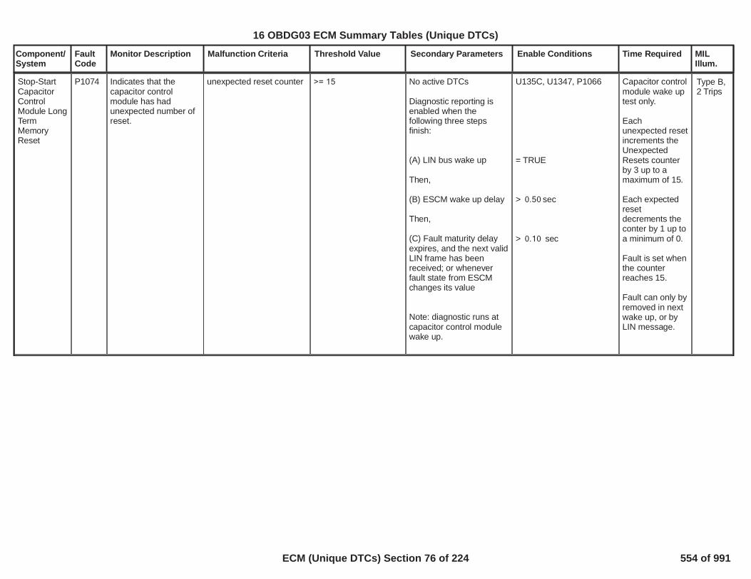
Component/System
FaultCode
Monitor Description Malfunction Criteria Threshold Value Secondary Parameters Enable Conditions Time Required MILIllum.
Stop-StartCapacitorControlModule LongTermMemoryReset
P1074 Indicates that thecapacitor controlmodule has hadunexpected number ofreset.
unexpected reset counter >= 15 No active DTCs
Diagnostic reporting isenabled when thefollowing three stepsfinish:
(A) LIN bus wake up
Then,
(B) ESCM wake up delay
Then,
(C) Fault maturity delayexpires, and the next validLIN frame has beenreceived; or wheneverfault state from ESCMchanges its value
Note: diagnostic runs atcapacitor control modulewake up.
U135C, U1347, P1066
= TRUE
> sec0.50
> sec0.10
Capacitor controlmodule wake uptest only.
Eachunexpected resetincrements theUnexpectedResets counterby 3 up to amaximum of 15.
Each expectedresetdecrements theconter by 1 up toa minimum of 0.
Fault is set whenthe counterreaches 15.
Fault can only byremoved in nextwake up, or byLIN message.
Type B,2 Trips
36
16 OBDG03 ECM Summary Tables (Unique DTCs)
ECM (Unique DTCs) Section 76 of 224 554 of 991

Component/System
FaultCode
Monitor Description Malfunction Criteria Threshold Value Secondary Parameters Enable Conditions Time Required MILIllum.
Voltage increase rate ofthe capacitor after 5seconds of charge
<10 mV/s No active DTCs
Diagnostic reporting isenabled when thefollowing three stepsfinish:
(A) LIN bus wake up
Then,
(B) ESCM wake up delay
Then,
(C) Fault maturity delayexpires, and the next validLIN frame has beenreceived; or wheneverfault state from ESCMchanges its value
Afterwards, this diagnosticruns when the followingconditions are met:
DCDC charging
Charging current
U135C, U1347, P1066
= TRUE
> sec0.50
> sec0.03
= active
>40 Amps
Detection isdone in the first 5seconds at eachcharge.
Fault is set atfirst detection.
Fault can only beremoved at nextwake up, or byLIN message.
Start-StopCapacitorSenseCircuit Low
P1075 Indicates that thecapacitor middle pointline is in an open circuitstate or there is a shortto GND or the capacitoris defective.
Type A,1 Trips
The capacitor (dual cell)mid point voltage beforestarting balance
The capacitor (dual cell)mid point voltage afterstarting balance.
Note: balance is to make
<0.1 V
>0.8 V
No active DTCs
Diagnostic reporting isenabled when thefollowing three stepsfinish:
(A) LIN bus wake up
U135C, U1347, P1066
= TRUE
Detect after eachbalance ofcapacitor cells.
Fault is set atfirst detection.
Once set, thisfault will inhibit
37
16 OBDG03 ECM Summary Tables (Unique DTCs)
ECM (Unique DTCs) Section 77 of 224 555 of 991

Component/System
FaultCode
Monitor Description Malfunction Criteria Threshold Value Secondary Parameters Enable Conditions Time Required MILIllum.
the capacitor voltageequally distributed to thetwo cells.
Then,
(B) ESCM wake up delay
Then,
(C) Fault maturity delayexpires, and the next validLIN frame has beenreceived; or wheneverfault state from ESCMchanges its value
Then,this diagnostic runs aftereach balance.
> sec0.50
> sec0.03
further cellsbalancing.
Fault can only beremoved in thenext wake up orby LIN message.
38
16 OBDG03 ECM Summary Tables (Unique DTCs)
ECM (Unique DTCs) Section 78 of 224 556 of 991

Component/System
FaultCode
Monitor Description Malfunction Criteria Threshold Value Secondary Parameters Enable Conditions Time Required MILIllum.
Start-StopCapacitorSenseCircuit High
P1076 Indicates that thecapacitor middle pointline shows highvoltage.
Capacitor mid point linevoltage > 4.8 V
No active DTCs
Diagnostic reporting isenabled when thefollowing three stepsfinish:
(A) LIN bus wake up
Then,(B) ESCM wake up delay
Then,(C) Fault maturity delayexpires, and the next validLIN frame has beenreceived; or wheneverfault state from ESCMchanges its value
Afterwards, this diagnosticruns continuously.
U135C, U1347, P1066
= TRUE
> sec0.50
> sec2.10
Test cycle time is100ms.
Error countincreases by 1 ifan error isdetected, up to amaximum of 20.
Error countdecreases by 1 ifno error isdetected, up to aminimum of 0.
Fault is set whenerror count = 20.(2 sec faultmaturity)
Fault is removedwhen error count= 0.(2 sec healingtime)
Type A,1 Trips
39
16 OBDG03 ECM Summary Tables (Unique DTCs)
ECM (Unique DTCs) Section 79 of 224 557 of 991

Component/System
FaultCode
Monitor Description Malfunction Criteria Threshold Value Secondary Parameters Enable Conditions Time Required MILIllum.
Stop-StartCapacitorControlModule LINSystemVoltage Low
P1077 Indicates that the LINsupply voltage is toolow.
LIN supply voltage < 9.12V No active DTCs
Diagnostic reporting isenabled when thefollowing steps (A)~(D)finish:
(A) LIN bus wake up
Then,(B) ESCM wake up delay
Then,(C) Engine run time
Then,(D) Fault maturity delaytime expires, and the nextvalid LIN frame has beenreceived; or wheneverfault state from ESCMchanges its value
Afterwards, this diagnosticruns when the followingconditions met:
Ground switch (K1)
Capactor switch (K2)
Engine run time aftereach auto stop event
U135C, U1347, P1066
= TRUE
> sec0.50
> sec2.0
> sec5.00
= Closed
= Open
> sec2.0
Test cycle time is10ms.
Error countincreases by 2 ifan error isdetected, up to amaximum of 100.
Error countdecreases by 1 ifno error isdetected up to aminimum of 0.
Fault is set whenerror count =100.(500ms faultmaturity)
Fault is removedwhen error count= 0.(1 sec healingtime)
Type B,2 Trips
40
16 OBDG03 ECM Summary Tables (Unique DTCs)
ECM (Unique DTCs) Section 80 of 224 558 of 991

Component/System
FaultCode
Monitor Description Malfunction Criteria Threshold Value Secondary Parameters Enable Conditions Time Required MILIllum.
Stop-StartCapacitorControlModule LINSystemVoltage High
P1078 Indicates that the LINsupply voltage is toohigh.
LIN supply voltage >17.16V No active DTCs
Diagnostic reporting isenabled when thefollowing three stepsfinish:
(A) LIN bus wake up
Then,(B) ESCM wake up delay
Then,(C) Fault maturity delayexpires, and the next validLIN frame has beenreceived; or wheneverfault state from ESCMchanges its value
Afterwards, this diagnosticruns when the followingconditions are met:
Ground switch (K1)
Capactor switch (K2)
U135C, U1347, P1066
= TRUE
> sec0.50
> sec5.00
= Closed
= Open
Test cycle time is10ms.
Error countincreases by 2 ifan error isdetected up to amaximum of 100.
Error countdecreases by 1 ifno error isdetected up to aminimum of 0.
Fault is set whenerror count =100.(500ms faultmaturity)
Fault is removedwhen error count= 0. (1 sechealing time)
Type B,2 Trips
41
16 OBDG03 ECM Summary Tables (Unique DTCs)
ECM (Unique DTCs) Section 81 of 224 559 of 991

Component/System
FaultCode
Monitor Description Malfunction Criteria Threshold Value Secondary Parameters Enable Conditions Time Required MILIllum.
Stop-StartCapacitorControlModule LINSystemVoltagePerformance
P1079 Indicates that thedifference between thereceived referencevoltage and themeasured LIN supplyvotlage is too high.
The absolute value ofdifference of the followingtwo items (A) and (B):
(A) measured LIN supplyvoltage
(B) received engine runcrank voltage from LINmessage
> 2.5VNo active DTCs
Diagnostic reporting isenabled when thefollowing steps (A)~(D)finish:
(A) LIN bus wake up
Then,(B) ESCM wake up delay
Then,(C) Engine Mode Run
Then,(D) Fault maturity delaytime expires, and the nextvalid LIN frame has beenreceived; or wheneverfault state from ESCMchanges its value
Afterwards, this diagnosticruns when the followingconditions are met:
Ground switch (K1)
Capactor switch (K2)
Engine run time aftereach auto stop event
U135C, U1347, P1066
= TRUE
> sec0.50
> sec2.0
> sec5.00
= Closed
= Open
> sec2.0
Test cycle time is100ms.
Error countincreases by 2 ifan error isdetected, up to amaximum of 10.
Error countdecreases by 1 ifno error isdetected up to aminimum of 0.
Fault is set whenerror count = 10.(500ms faultmaturity)
Fault is removedwhen error count= 0.(1 sec healingtime)
Type B,2 Trips
42
16 OBDG03 ECM Summary Tables (Unique DTCs)
ECM (Unique DTCs) Section 82 of 224 560 of 991
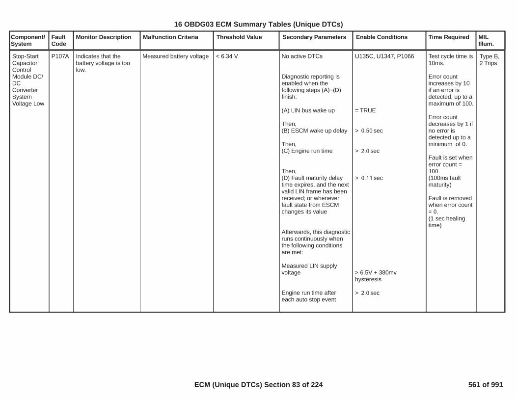
Component/System
FaultCode
Monitor Description Malfunction Criteria Threshold Value Secondary Parameters Enable Conditions Time Required MILIllum.
Stop-StartCapacitorControlModule DC/DCConverterSystemVoltage Low
P107A Indicates that thebattery voltage is toolow.
Measured battery voltage < 6.34 V No active DTCs
Diagnostic reporting isenabled when thefollowing steps (A)~(D)finish:
(A) LIN bus wake up
Then,(B) ESCM wake up delay
Then,(C) Engine run time
Then,(D) Fault maturity delaytime expires, and the nextvalid LIN frame has beenreceived; or wheneverfault state from ESCMchanges its value
Afterwards, this diagnosticruns continuously whenthe following conditionsare met:
Measured LIN supplyvoltage
Engine run time aftereach auto stop event
U135C, U1347, P1066
= TRUE
> sec0.50
> sec2.0
> sec0.11
> 6.5V + 380mvhysteresis
> sec2.0
Test cycle time is10ms.
Error countincreases by 10if an error isdetected, up to amaximum of 100.
Error countdecreases by 1 ifno error isdetected up to aminimum of 0.
Fault is set whenerror count =100.(100ms faultmaturity)
Fault is removedwhen error count= 0.(1 sec healingtime)
Type B,2 Trips
43
16 OBDG03 ECM Summary Tables (Unique DTCs)
ECM (Unique DTCs) Section 83 of 224 561 of 991

Component/System
FaultCode
Monitor Description Malfunction Criteria Threshold Value Secondary Parameters Enable Conditions Time Required MILIllum.
Stop-StartCapacitorControlModule DC/DCConverterSystemVoltage High
P107B Indicates that thebattery voltage is toohigh.
Measured battery voltage > 17.06V No active DTCs
Diagnostic reporting isenabled when thefollowing three stepsfinish:
(A) LIN bus wake up
Then,(B) ESCM wake up delay
Then,(C) Fault maturity delayexpires, and the next validLIN frame has beenreceived; or wheneverfault state from ESCMchanges its value
Afterwards, this diagnosticruns continuously whenthe following conditionsare met:
Measured LIN supplyvoltage
U135C, U1347, P1066
= TRUE
> sec0.50
> sec0.11
> 6.5V + 380mvhysteresis
Test cycle time is10ms.
Error countincreases by 10if an errordetection occursup to a maximumof 100.
Error countdecreases by 1 ifno errordetection occursup to a minimumof 0.
Fault is set whenerror count =100.(100ms faultmaturity)
Fault is removedwhen error count= 0.(1 sec healingtime).
Type B,2 Trips
44
16 OBDG03 ECM Summary Tables (Unique DTCs)
ECM (Unique DTCs) Section 84 of 224 562 of 991

Component/System
FaultCode
Monitor Description Malfunction Criteria Threshold Value Secondary Parameters Enable Conditions Time Required MILIllum.
Stop-StartCapacitorControlModule DC/DCConverterSupplyVoltageCircuitPerformance
P107C Indicates that thedifference between thereceived reference andthe measured value ofthe battery voltage istoo high.
The absolute value ofdifference between thefollowing two items (A)and (B):
(A) Mesured batteryvoltage
(B) Received engine runcrank voltage
> 2.5VNo active DTCs
Diagnostic reporting isenabled when thefollowing steps (A)~(D)finish:
(A) LIN bus wake up
Then,(B) ESCM wake up delay
Then,(C) Engine run time
Then,(D) Fault maturity delaytime expires, and the nextvalid LIN frame has beenreceived; or wheneverfault state from ESCMchanges its value
Afterwards, this diagnosticruns when the followingconditions are met:
Ground swith (K1)
Capacitor switch (K2)
Engine run time aftereach auto stop event
U135C, U1347, P1066
= TRUE
> sec0.50
> sec2.0
> sec5.00
= closed
= open
> sec2.0
Test cycle time is100ms.
Error countincreases by 2 ifan error isdetected up to amaximum of 10.
Error countdecreases by 1 ifno error isdetected up to aminimum of 0.
Fault is set whenerror count = 10.(500ms faultmaturity)
Fault is removedwhen error count= 0.(1 sec healingtime)
Type B,2 Trips
45
16 OBDG03 ECM Summary Tables (Unique DTCs)
ECM (Unique DTCs) Section 85 of 224 563 of 991

Component/System
FaultCode
Monitor Description Malfunction Criteria Threshold Value Secondary Parameters Enable Conditions Time Required MILIllum.
Stop-StartControlModuleBackupSystemVoltage Low
P107D Indicates that theexternal safe supplyvoltage is too low.
measured external safesupply voltage < 62% of the measured
battery voltage
No active DTCs
Diagnostic reporting isenabled when thefollowing steps (A)~(D)finish:
(A) LIN bus wake up
Then,(B) ESCM wake up delay
Then,(C) Engine run time
Then,(D) Fault maturity delaytime expires, and the nextvalid LIN frame has beenreceived; or wheneverfault state from ESCMchanges its value
Afterwards, this diagnosticruns continuously whenthe following conditionsare met:
Measured LIN supplyvoltage
Engine run time aftereach auto stop event
U135C, U1347, P1066
= TRUE
> sec0.50
> sec2.0
> sec0.60
> 6.5V + 380mvhysteresis
> sec2.0
Test cycle time is100ms.
Error countincreases by 2 ifan error isdetected, up to amaximum of 10.
Error countdecreases by 1 ifno error isdetected, up to aminimum of 0.
Fault is set whenerror count = 10.(500ms faultmaturity)
Fault is removedwhen error count= 0.(1sec healingtime)
Type B,2 Trips
46
16 OBDG03 ECM Summary Tables (Unique DTCs)
ECM (Unique DTCs) Section 86 of 224 564 of 991

Component/System
FaultCode
Monitor Description Malfunction Criteria Threshold Value Secondary Parameters Enable Conditions Time Required MILIllum.
Stop-StartControlModuleBackupSystemVoltage High
P107E Indicates that theexternal safe supplyvoltage is too high.
Measured external safesupply voltage > 17.16 V
No active DTCs
Diagnostic reporting isenabled when thefollowing three stepsfinish:
(A) LIN bus wake up
Then,(B) ESCM wake up delay
Then,(C) Fault maturity delayexpires, and the next validLIN frame has beenreceived; or wheneverfault state from ESCMchanges its value
Aftterwards, thisdiagnostic runs when thefollowing conditions aremet:
Ground switch (K1)
Capacitor switch (K2)
U135C, U1347, P1066
= TRUE
> sec0.50
> sec5.00
= close
= open
Test cycle time is100ms.
Error countincreases by 2 ifan error isdetected, up to amaximum of 10.
Error countdecreases by 1 ifno error isdetected, up to aminimum of 0.
Fault is set whenerror count = 10.(500ms faultmaturity)
Fault is removedwhen error count= 0.(1 sec healingtime)
Type B,2 Trips
47
16 OBDG03 ECM Summary Tables (Unique DTCs)
ECM (Unique DTCs) Section 87 of 224 565 of 991

Component/System
FaultCode
Monitor Description Malfunction Criteria Threshold Value Secondary Parameters Enable Conditions Time Required MILIllum.
Stop-StartControlModuleBackupSystemVoltagePerformance
P107F Indicates that thedifference between thereceived reference andthe measured value ofthe external safesupply voltage is toohigh.
Absolute value ofdifference of the followingtwo items (A) and (B):
(A) measured extrnal safesupply voltage
(B) received engine runcrank voltage
> 2.5 VNo active DTCs
Diagnostic reporting isenabled when thefollowing steps (A)~(D)finish:
(A) LIN bus wake up
Then,(B) ESCM wake up delay
Then,(C) Engine run time
Then,(D) Fault maturity delaytime expires, and the nextvalid LIN frame has beenreceived; or wheneverfault state from ESCMchanges its value
Afterwards,this diagnostic runs whenthe following conditionsare met:
Ground switch (K1)
Capacitor switch (K2)
Engine run time aftereach auto stop event
U135C, U1347, P1066
= TRUE
> sec0.50
> sec2.0
> sec5.00
= close
= open
> sec2.0
Test cycle time is100ms.
Error countincreases by 2 ifan error isdetected, up to amaximum of 10.
Error countdecreases by 1 ifno error isdetected, up to aminimum of 0.
Fault is set whenerror count = 10.(500ms faultmaturity)
Fault is removedwhen error count= 0.(1 sec healingtime)
Type B,2 Trips
48
16 OBDG03 ECM Summary Tables (Unique DTCs)
ECM (Unique DTCs) Section 88 of 224 566 of 991

Component/System
FaultCode
Monitor Description Malfunction Criteria Threshold Value Secondary Parameters Enable Conditions Time Required MILIllum.
Stop-StartCapacitorControlModuleBatteryNegativeCircuit Driver"A" Low
P1080 Indicates that theground switch (K1)bank A driver is stuck atopen when should beclosed
Gound switch (K1) bank Agate voltage is low.
Note: the gate voltage isto assure that the switchstays closed whencommanded.
< 10.5VNo active DTCs
Diagnostic reporting isenabled when thefollowing three stepsfinish:
(A) LIN bus wake up
Then,(B) ESCM wake up delay
Then,(C) Fault maturity delayexpires, and the next validLIN frame has beenreceived; or wheneverfault state from ESCMchanges its value
Afterwards, this diagnosticruns when the followingconditions are met:
Measured LIN supplyvoltage
Ground switch (K1) iscommanded to closeaccording to flip-flopoutput
U135C, U1347, P1066
= TRUE
> sec0.50
> sec0.50
> 6.5V+380 mv hysteresis
= TRUE
Test cycle time is5ms.
Error countincreases by 2 ifan errordetection occursup to a maximumof 200.
Error countdecreases by 1 ifno errordetection occursup to a minimumof 0.
Fault is set whenerror count =200.(500ms faultmaturity)
Fault is removedwhen error count= 0.(1 sec healingtime)
Type A,1 Trips
49
16 OBDG03 ECM Summary Tables (Unique DTCs)
ECM (Unique DTCs) Section 89 of 224 567 of 991

Component/System
FaultCode
Monitor Description Malfunction Criteria Threshold Value Secondary Parameters Enable Conditions Time Required MILIllum.
Stop-StartCapacitorControlModuleBatteryNegativeCircuit Driver"A" High
P1081 Indicates that theground switch (K1)bank A driver is stuck atclosed when should beopen
Ground switch (K1) bankA gate voltage > 2.0 V
No active DTCs
Diagnostic reporting isenabled when thefollowing three stepsfinish:
(A) LIN bus wake up
Then,(B) ESCM wake up delay
Then,(C) Fault maturity delayexpires, and the next validLIN frame has beenreceived; or wheneverfault state from ESCMchanges its value
Afterwards, this diagnosticruns when the followingconditions are met:
Ground switch (K1) iscommaned to openaccording to flip-flopoutput
U135C, U1347, P1066
= TRUE
> sec0.50
> sec0.05
= TRUE
Test cycle time is5ms.
Error countincreases by 20if an errordetection occursup to a maximumof 200.
Error countdecreases by 1 ifno errordetection occursup to a minimumof 0.
Fault is set whenerror count =200.(500ms faultmaturity)
Fault is removedwhen error count= 0.(1 sec healingtime)
Type A,1 Trips
50
16 OBDG03 ECM Summary Tables (Unique DTCs)
ECM (Unique DTCs) Section 90 of 224 568 of 991

Component/System
FaultCode
Monitor Description Malfunction Criteria Threshold Value Secondary Parameters Enable Conditions Time Required MILIllum.
Stop-StartCapacitorControlModuleBatteryNegativeCircuit Driver"A"-"B" NotPlausible
P108A Indicates that thedifference between theground switch (K1)bank A gate voltageand bank B gatevoltage is too high.
The absolute value ofdifference between thefollowing two items (A)and (B)
(A) K1A gate voltage(B) K1B gate voltage
> 2.0 VNo active DTCs
Diagnostic reporting isenabled when thefollowing three stepsfinish:
(A) LIN bus wake up
Then,(B) ESCM wake up delay
Then,(C) Fault maturity delayexpires, and the next validLIN frame has beenreceived; or wheneverfault state from ESCMchanges its value
Afterwards, this diagnosticruns continuously
U135C, U1347, P1066
= TRUE
> sec0.50
> sec5.00
Test cycle time is100ms.
Error countincreases by 2 ifan errordetection occursup to a maximumof 10.
Error countdecreases by 1 ifno errordetection occursup to a minimumof 0.
Fault is set whenerror count = 10.(500ms faultmaturity)
Fault is removedwhen error count= 0.(1 sec healingtime)
Type B,2 Trips
51
16 OBDG03 ECM Summary Tables (Unique DTCs)
ECM (Unique DTCs) Section 91 of 224 569 of 991

Component/System
FaultCode
Monitor Description Malfunction Criteria Threshold Value Secondary Parameters Enable Conditions Time Required MILIllum.
Stop-StartCapacitorControlModuleBatteryNegativeCircuit Driver"B" Low
P108B Indicates that theground switch (K1)bank B driver is stuckat open when shouldbe closed
Gound switch (K1) bank Bgate voltage <10.5 V
No active DTCs
Diagnostic reporting isenabled when thefollowing three stepsfinish:
(A) LIN bus wake up
Then,(B) ESCM wake up delay
Then,(C) Fault maturity delayexpires, and the next validLIN frame has beenreceived.
Afterwards, this diagnosticruns when the followingconditions are met:
Measured LIN supplyvoltage
Ground switch (K1) iscommanded to closeaccording to flip-flopoutput
U135C, U1347, P1066
= TRUE
> sec0.50
> sec0.50
>6.5V+380mv hysteresis
= TRUE
Test cycle time is5ms.
Error countincreases by 2 ifan errordetection occursup to a maximumof 200.
Error countdecreases by 1 ifno errordetection occursup to a minimumof 0.
Fault is set whenerror count =200.(500ms faultmaturity)
Fault is removedwhen error count= 0.(1 sec healingtime)
Type A,1 Trips
52
16 OBDG03 ECM Summary Tables (Unique DTCs)
ECM (Unique DTCs) Section 92 of 224 570 of 991

Component/System
FaultCode
Monitor Description Malfunction Criteria Threshold Value Secondary Parameters Enable Conditions Time Required MILIllum.
Stop-StartCapacitorControlModuleBatteryNegativeCircuit Driver"B" High
P108C Indicates that theground switch (K1)bank B is stuck atclosed when should beopen
Ground switch (K1) bankB gate voltage >2.0 V
No active DTCs
Diagnostic reporting isenabled when thefollowing three stepsfinish:
(A) LIN bus wake up
Then,(B) ESCM wake up delay
Then,(C) Fault maturity delayexpires, and the next validLIN frame has beenreceived.
Afterwards, this diagnosticruns when the followingconditions are met:
Ground switch (K1) iscommanded to closeaccording to flip-flopoutput
U135C, U1347, P1066
= TRUE
> sec0.50
> sec0.05
= TRUE
Test cycle time is5ms.
Error countincreases by 20if an errordetection occursup to a maximumof 200.
Error countdecreases by 1 ifno errordetection occursup to a minimumof 0.
Fault is set whenerror count =200.(500ms faultmaturity)
Fault is removedwhen error count= 0.(1 sec healingtime)
Type A,1 Trips
53
16 OBDG03 ECM Summary Tables (Unique DTCs)
ECM (Unique DTCs) Section 93 of 224 571 of 991

Component/System
FaultCode
Monitor Description Malfunction Criteria Threshold Value Secondary Parameters Enable Conditions Time Required MILIllum.
DCDC does not stopcharging when requsted
Charging current >10A
No active DTCs
Diagnostic reporting isenabled when thefollowing three stepsfinish:
(A) LIN bus wake up
Then,(B) ESCM wake up delay
Then,(C) Fault maturity delayexpires, and the next validLIN frame has beenreceived; or wheneverfault state from ESCMchanges its value
Afterwards, this diagnosticruns when the followingconditions are met:
DCDC disabledORDCDC discharging
U135C, U1347, P1066
= TRUE
> sec0.50
> sec15.00
= TRUE
= TRUE
Test cycle time is10ms.
Error countincreases by 1 ifan errordetection occursup to a maximumof 200.
Error countdecreases by 2 ifno errordetection occursup to a minimumof 0.
Fault is set whenerror count =200.(500ms faultmaturity)
Fault is removedwhen error count= 0.(1 sec healingtime)
Stop-StartCapacitorControlModule DC/DCConverterDischargingPerformance
P108D Indicates that one ormore of the followingfaults have occurred:Case 1) DCDC doesnot stop charging whenrequested;Case 2) DCDC isunable to discharge thecapacitor
Type A,1 Trips
54
16 OBDG03 ECM Summary Tables (Unique DTCs)
ECM (Unique DTCs) Section 94 of 224 572 of 991

Component/System
FaultCode
Monitor Description Malfunction Criteria Threshold Value Secondary Parameters Enable Conditions Time Required MILIllum.
DCDC is unable todischarge the capacitor:
Capacitor voltagedecrease rate < 6 mv/second
in first 15 secdischarging time
No active DTCs
Diagnostic reporting isenabled when thefollowing three stepsfinish:
(A) LIN bus wake up
Then,(B) ESCM wake up delay
Then,(C) Fault maturity delayexpires, and the next validLIN frame has beenreceived; or wheneverfault state from ESCMchanges its value
Afterwards, this diagnosticruns when the followingconditions are met:
DCDC discharging
Capacitor voltage
U135C, U1347, P1066
= TRUE
> sec0.50
> sec15.00
= TRUE
> 0.5 V
Detect duringfirst 15 secondsot discharging.
Fault is set afterfirst detection.
Fault can only beremoved in thenext wake up, orby LIN message.
55
16 OBDG03 ECM Summary Tables (Unique DTCs)
ECM (Unique DTCs) Section 95 of 224 573 of 991
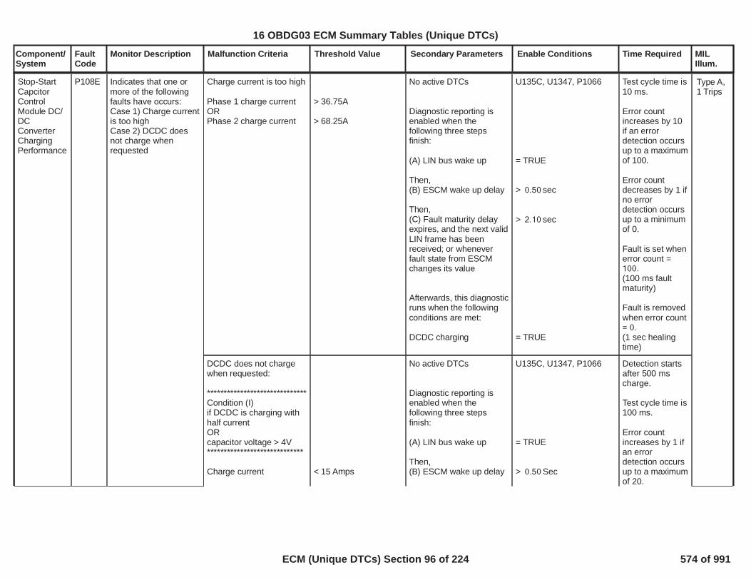
Component/System
FaultCode
Monitor Description Malfunction Criteria Threshold Value Secondary Parameters Enable Conditions Time Required MILIllum.
Charge current is too high
Phase 1 charge currentORPhase 2 charge current
> 36.75A
> 68.25A
No active DTCs
Diagnostic reporting isenabled when thefollowing three stepsfinish:
(A) LIN bus wake up
Then,(B) ESCM wake up delay
Then,(C) Fault maturity delayexpires, and the next validLIN frame has beenreceived; or wheneverfault state from ESCMchanges its value
Afterwards, this diagnosticruns when the followingconditions are met:
DCDC charging
U135C, U1347, P1066
= TRUE
> sec0.50
> sec2.10
= TRUE
Test cycle time is10 ms.
Error countincreases by 10if an errordetection occursup to a maximumof 100.
Error countdecreases by 1 ifno errordetection occursup to a minimumof 0.
Fault is set whenerror count =100.(100 ms faultmaturity)
Fault is removedwhen error count= 0.(1 sec healingtime)
Stop-StartCapcitorControlModule DC/DCConverterChargingPerformance
P108E Indicates that one ormore of the followingfaults have occurs:Case 1) Charge currentis too highCase 2) DCDC doesnot charge whenrequested
Type A,1 Trips
DCDC does not chargewhen requested:
******************************Condition (I)if DCDC is charging withhalf currentORcapacitor voltage > 4V*****************************
Charge current < 15 Amps
No active DTCs
Diagnostic reporting isenabled when thefollowing three stepsfinish:
(A) LIN bus wake up
Then,(B) ESCM wake up delay
U135C, U1347, P1066
= TRUE
> Sec0.50
Detection startsafter 500 mscharge.
Test cycle time is100 ms.
Error countincreases by 1 ifan errordetection occursup to a maximumof 20.
56
16 OBDG03 ECM Summary Tables (Unique DTCs)
ECM (Unique DTCs) Section 96 of 224 574 of 991

Component/System
FaultCode
Monitor Description Malfunction Criteria Threshold Value Secondary Parameters Enable Conditions Time Required MILIllum.
******************************Condtion (II)if DCDC is charging withfull currentANDcapacitor voltage <= 4 V******************************
Charge current < 30 Amps
Then,(C) Fault maturity delayexpires, and the next validLIN frame has beenreceived.
Note: After intial timedelay, diagnostic runs ifthe following conditionssatisfy:
DCDC charging
DCDC charging time
> sec2.10
= TRUE
>= 500 ms
Error countdecreases by 1 ifno errordetection occursup to a minimumof 0.
Fault is set whenerror count = 20.
Fault is removedwhen error count= 0.
57
16 OBDG03 ECM Summary Tables (Unique DTCs)
ECM (Unique DTCs) Section 97 of 224 575 of 991

Component/System
FaultCode
Monitor Description Malfunction Criteria Threshold Value Secondary Parameters Enable Conditions Time Required MILIllum.
Unable to switch over tocapacitor swith (K2)during self test if either (A)or (B) is TRUE:
(A) Hardware currentcomparator output stuckat passive.And, the measuredbattery voltage
Note: hardware currentcomparator is used toautomatically provoke aswitch if the currentflowing through theground switch (K2) isgreater than a threshold.
(B) Hardware voltagecomparator is stuck atpassive.And, the measuredbattery voltage
Note: hardware voltagecomparator is used toautomatically provoke aswitch if the batteryvoltage is less than athreshold.
< 13.3 V
>= 13.3 V
No active DTCs
Diagnostic reporting isenabled when thefollowing steps finish:
(A) LIN bus wake up
Then,(B) ESCM wake up delay
Then,(C) Fault maturity delayexpires, and the next validLIN frame has beenreceived; or wheneverfault state from ESCMchanges its value
And,(D) Fault is detecedfollowing previous drivecycle during powerdownself test.
Note: This is notcontinuous diagnostic.
U135C, U1347, P1066
= TRUE
> sec0.50
> sec0.10
Detect duringpart two of theself testprocedure only ifthere was noswitch in thedrving cycle.
Self testprocedure isperformed at theend of the drivecycle afterESCM is not inworking state,i.e. no LINcommnication.Self test lasts for130 seconds.
Fault is set afterfirst detection.
Fault can only beremoved in thefollowing drivingcycle when selftest runs again.
Stop-StartCapacitorControlModule SelfTest Failed
P108F Indicates that one oremore of the followingfaults have occurred:Case 1) Unable toswitch over to capacitorswitch (K2) during selftest;Case 2) An unintendedswitchover to capacitorswitch (K2) during selftest;Case 3) Capacitorswitch (K2) is in a highimpedance state ordiode mode during selftest;
Type A,1 Trips
Uintended switchover tocapacitor switch (K2)during self test if either (A)or (B) is TRUE:
(A) Hardware currentcomparator output isalways triggerred.And, the measured
No active DTCs
Diagnostic reporting isenabled when thefollowing steps finish:
(A) LIN bus wake up
U135C, U1347, P1066
= TRUE
Detect duringpart one of theself testprocedure.
Self testprocedure isperformed at theend of the drive
16 OBDG03 ECM Summary Tables (Unique DTCs)
ECM (Unique DTCs) Section 98 of 224 576 of 991
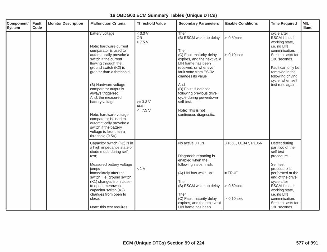
Component/System
FaultCode
Monitor Description Malfunction Criteria Threshold Value Secondary Parameters Enable Conditions Time Required MILIllum.
battery voltage
Note: hardware currentcomparator is used toautomatically provoke aswitch if the currentflowing through theground switch (K2) isgreater than a threshold.
(B) Hardware voltagecomparator output isalways triggerred.And, the measuredbattery voltage
Note: hardware voltagecomparator is used toautomatically provoke aswitch if the batteryvoltage is less than athreshold (9.5V)
< 3.3 VOR> 7.5 V
>= 3.3 VAND<= 7.5 V
Then,(B) ESCM wake up delay
Then,(C) Fault maturity delayexpires, and the next validLIN frame has beenreceived; or wheneverfault state from ESCMchanges its value
And,(D) Fault is detecedfollowing previous drivecycle during powerdownself test.
Note: This is notcontinuous diagnostic.
> sec0.50
> sec0.10
cycle afterESCM is not inworking state,i.e. no LINcommnication.Self test lasts for130 seconds.
Fault can only beremoved in thefollowing drivingcycle when selftest runs again.
Capacitor switch (K2) is ina high impedance state ordiode mode during selftest;
Measured battery voltagejumpsimmediately after theswitch, i.e. ground switch(K1) changes from closeto open, meanwhilecapacitor switch (K2)changes from open toclose.
Note: this test requires
< 1 V
No active DTCs
Diagnostic reporting isenabled when thefollowing steps finish:
(A) LIN bus wake up
Then,(B) ESCM wake up delay
Then,(C) Fault maturity delayexpires, and the next validLIN frame has been
U135C, U1347, P1066
= TRUE
> sec0.50
> sec0.10
Detect duringpart two of theself testprocedure.
Self testprocedure isperformed at theend of the drivecycle afterESCM is not inworking state,i.e. no LINcommnication.Self test lasts for130 seconds.
16 OBDG03 ECM Summary Tables (Unique DTCs)
ECM (Unique DTCs) Section 99 of 224 577 of 991

Component/System
FaultCode
Monitor Description Malfunction Criteria Threshold Value Secondary Parameters Enable Conditions Time Required MILIllum.
that measured capacitorvoltage > 2.0 V
received; or wheneverfault state from ESCMchanges its value
And,(D) Fault is detecedfollowing previous drivecycle during powerdownself test.
Fault can only beremoved in thefollowing drivingcycle when selftest runs again.
16 OBDG03 ECM Summary Tables (Unique DTCs)
ECM (Unique DTCs) Section 100 of 224 578 of 991

Component/System
FaultCode
Monitor Description Malfunction Criteria Threshold Value Secondary Parameters Enable Conditions Time Required MILIllum.
Stop-StartCapacitorControlModuleInternalCircuitryPerformance
P1090 Indicates a powerinterconnection defecton control board/powerboard
Measured 2.5V referencevoltage <2.18V
OR>2.83V
No active DTCs
Diagnostic reporting isenabled when thefollowing three stepsfinish:
(A) LIN bus wake up
Then,(B) ESCM wake up delay
Then,(C) Fault maturity delayexpires, and the next validLIN frame has beenreceived; or wheneverfault state from ESCMchanges its value
Afterwards, this diagnosticruns when the followingconditions are met:
Internal power supply
DCDC charging ORdischarging
U135C, U1347, P1066
= TRUE
> sec0.50
> sec0.51
= OK
= TRUE
Test cycle time is10ms.
Error countincreases by 2 ifan errordetection occursup to a maximumof 100.
Error countdecreases by 1 ifno errordetection occursup to a minimumof 0.
Fault is set whenerror count =100.(500ms faultmaturity)
Fault is removedwhen error count= 0.(1 sec healingtime)
Type A,1 Trips
61
16 OBDG03 ECM Summary Tables (Unique DTCs)
ECM (Unique DTCs) Section 101 of 224 579 of 991

Component/System
FaultCode
Monitor Description Malfunction Criteria Threshold Value Secondary Parameters Enable Conditions Time Required MILIllum.
Ground switch (K1)current measurement
AND
Capcitor switch currentmeasurement
< -120 Amps
> 60Amps
No active DTCs
Diagnostic reporting isenabled when thefollowing three stepsfinish:
(A) LIN bus wake up
Then,(B) ESCM wake up delay
Then,(C) Fault maturity delayexpires, and the next validLIN frame has beenreceived; or wheneverfault state from ESCMchanges its value.
Afterwards, this diagnosticruns when the followingconditions are met:
Capacitor switch (K2)closed
U135C, U1347, P1066
= TRUE
> sec0.50
> sec0.03
= TRUE
Test cycle time is1ms.
Error countincreases by 10if an errordetection occursup to a maximumof 100.
Error countdecreases by 1 ifno errordetection occursup to a minimumof 0.
Fault is set whenerror count =100.(10ms faultmaturity)
Fault is removedwhen error count= 0.(100ms healingtime)
Stop-StartCapacitorControlModuleSwitchDeteriorated
P1091 Indicates one or moreof the following faultshave occurred:Case 1) Ground switch(K1) is in short circuitwhen it should be openCase 2) Capacitorswitch (K2) is in a highimpedance or in diodemode when it shouldbe closed.Case 3) Capacitorswitch (K2) closecommand does notclose K2 whenrequired.Case 4) Capacitorcontrol module hasreached its end of life.
Type A,1 Trips
Measured ground switch(K1) current
AND
Measured capacitorswitch (K2) current
> 40A
< 30A
No active DTCs
Diagnostic reporting isenabled when thefollowing three stepsfinish:
(A) LIN bus wake up
Then,(B) ESCM wake up delay
U135C, U1347, P1066
= TRUE
> sec0.50
Test cycle time is1ms.
Error countincreases by 10if an errordetection occursup to a maximumof 100.
Error countdecreases by 1 ifno error
62
16 OBDG03 ECM Summary Tables (Unique DTCs)
ECM (Unique DTCs) Section 102 of 224 580 of 991

Component/System
FaultCode
Monitor Description Malfunction Criteria Threshold Value Secondary Parameters Enable Conditions Time Required MILIllum.
Then,(C) Fault maturity delayexpires, and the next validLIN frame has beenreceived; or wheneverfault state from ESCMchanges its value
Afterwards, this diagnosticruns when the followingconditions are met:
Capacitor switch (K2)
> sec0.03
= Closed
detection occursup to a minimumof 0.
Fault is set whenerror count =100.(10 ms faultmaturity)
Fault is removedwhen error count= 0.(100ms healingtime)
Capacitor switch (K2)stuck at open when itshould be closed
n.a. No active DTCs
Diagnostic reporting isenabled when thefollowing three stepsfinish:
(A) LIN bus wake up
Then,(B) Diagnostic delay
Then,(C) Fault maturity delayexpires, and the next validLIN frame has beenreceived; or wheneverfault state from ESCMchanges its value
Afterwards, this diagnosticruns when the followingconditions are met:
U135C, U1347, P1066
= TRUE
> sec0.50
> sec0.03
Test cycle time is10ms.
Error countincreases by 34if an errordetection occursup to a maximumof 102.
Error countdecreases by 1 ifno errordetection occursup to a minimumof 0.
Fault is set whenerror count =102.(30ms faultmaturity)
Fault is removedwhen error count
63
16 OBDG03 ECM Summary Tables (Unique DTCs)
ECM (Unique DTCs) Section 103 of 224 581 of 991

Component/System
FaultCode
Monitor Description Malfunction Criteria Threshold Value Secondary Parameters Enable Conditions Time Required MILIllum.
Capacitor switch (K2) iscommanded to close,according to flip-flopoutput = TRUE
= 0.(1.2 sec healingtime)
Number of switchbacksbetween ground switch(K1) and capacitor switch(K2)
> 2 million times No active DTCs
Diagnostic reporting isenabled when thefollowing three stepsfinish:
(A) LIN bus wake up
Then,(B) ESCM wake up delay
Then,(C) Fault maturity delayexpires, and the next validLIN frame has beenreceived; or wheneverfault state from ESCMchanges its value
Afterwards, this diagnosticruns continuously.
U135C, U1347, P1066
= TRUE
> sec0.50
> sec0.03
Detect afterevery switch-back.
Fault is set afterfirst detection.
This fault ispermament, canonly be removedby service tool.
64
16 OBDG03 ECM Summary Tables (Unique DTCs)
ECM (Unique DTCs) Section 104 of 224 582 of 991
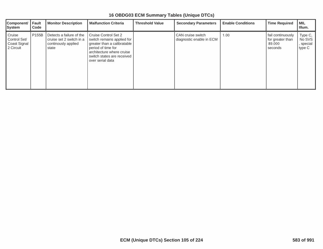
Component/System
FaultCode
Monitor Description Malfunction Criteria Threshold Value Secondary Parameters Enable Conditions Time Required MILIllum.
CruiseControl Set/Coast Signal2 Circuit
P155B Detects a failure of thecruise set 2 switch in acontinously appliedstate
Cruise Control Set 2switch remains applied forgreater than a calibratableperiod of time forarchitecture where cruiseswitch states are receivedover serial data
CAN cruise switchdiagnostic enable in ECM
1.00 fail continuouslyfor greater than89.000seconds
Type C,No SVS, specialtype C
65
16 OBDG03 ECM Summary Tables (Unique DTCs)
ECM (Unique DTCs) Section 105 of 224 583 of 991
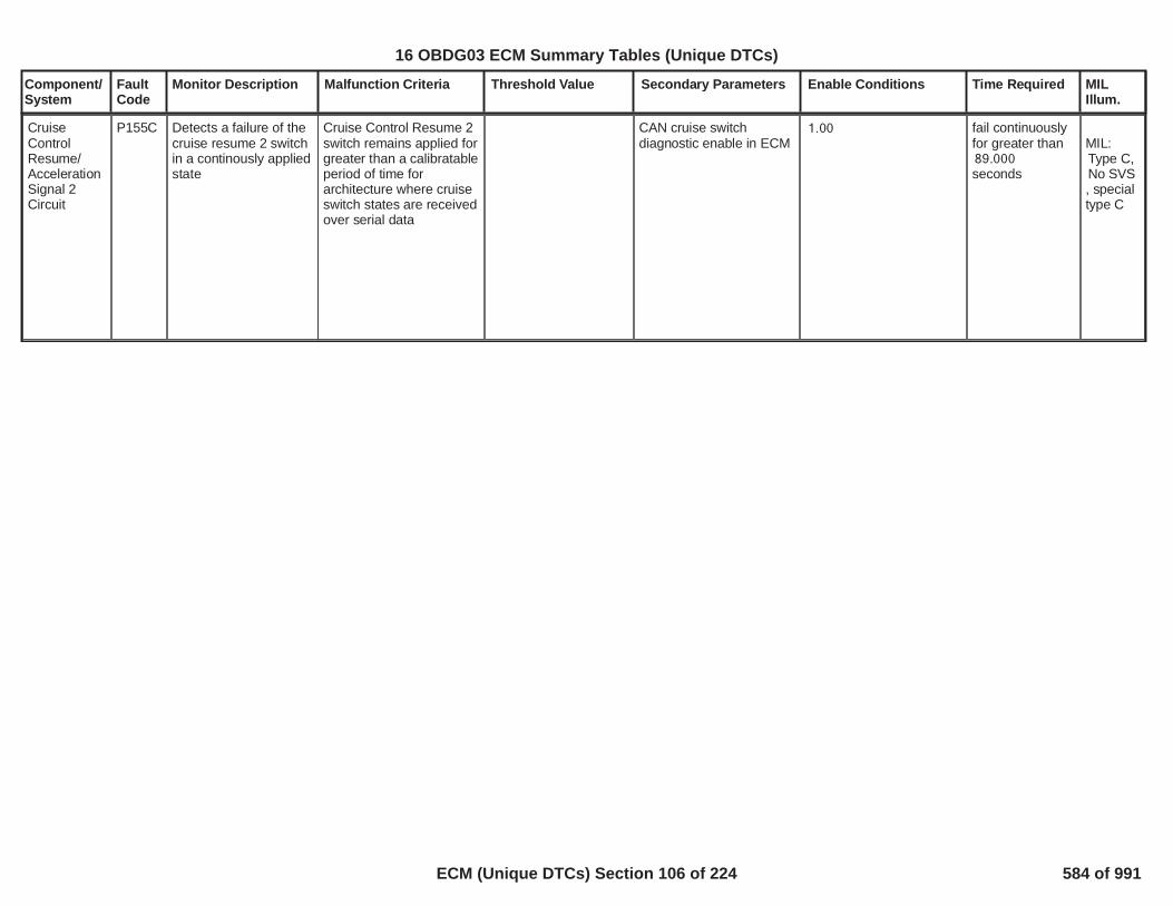
Component/System
FaultCode
Monitor Description Malfunction Criteria Threshold Value Secondary Parameters Enable Conditions Time Required MILIllum.
CruiseControlResume/AccelerationSignal 2Circuit
P155C Detects a failure of thecruise resume 2 switchin a continously appliedstate
Cruise Control Resume 2switch remains applied forgreater than a calibratableperiod of time forarchitecture where cruiseswitch states are receivedover serial data
CAN cruise switchdiagnostic enable in ECM
1.00 fail continuouslyfor greater than89.000seconds
MIL:Type C,No SVS, specialtype C
66
16 OBDG03 ECM Summary Tables (Unique DTCs)
ECM (Unique DTCs) Section 106 of 224 584 of 991

Component/System
FaultCode
Monitor Description Malfunction Criteria Threshold Value Secondary Parameters Enable Conditions Time Required MILIllum.
AnalogMode SwitchCircuit Low
P159F This DTC will detect ananalog mode switchinput that is too low outof range. For button type
Normal_Button
Analog Mode Switch lowvoltage threshold % of 5Vrange
For button typeEnhanced_Button
Analog Mode Switch lowvoltage threshold % of 5Vrange
For button typeMulitple_Button
Analog Mode Switch lowvoltage threshold % of 5Vrange
< %24.30
< %24.30
< %21.20
Vehicle mode analogswitch button type
=CeDMDG_e_Enhanced_Button
failures out200of samples250
25 ms / sample
Type B,2 Trips
67
16 OBDG03 ECM Summary Tables (Unique DTCs)
ECM (Unique DTCs) Section 107 of 224 585 of 991

Component/System
FaultCode
Monitor Description Malfunction Criteria Threshold Value Secondary Parameters Enable Conditions Time Required MILIllum.
AnalogMode SwitchCircuit High
P15A0 This DTC will detect ananalog mode switchinput that is too highout of range.
For button typeNormal_Button
Analog Mode Switch highvoltage threshold % of 5Vrange
For button typeEnhanced_Button
Analog Mode Switch highvoltage threshold % of 5Vrange
For button typeMulitple_Button
Analog Mode Switch highvoltage threshold % of 5Vrange
>= %94.10
>= %94.10
>= %95.30
Vehicle mode analogswitch button type
=CeDMDG_e_Enhanced_Button
failures out200of samples250
25 ms / sample
Type B,2 Trips
68
16 OBDG03 ECM Summary Tables (Unique DTCs)
ECM (Unique DTCs) Section 108 of 224 586 of 991

Component/System
FaultCode
Monitor Description Malfunction Criteria Threshold Value Secondary Parameters Enable Conditions Time Required MILIllum.
AnalogMode SwitchPerformance
P15A1 This DTC will detect ananalog mode switchinput that is in anindeterminate range.
For button typeNormal_Button
Analog Mode Switchindeterminate region % of5V range
For button typeEnhanced_Button
Analog Mode Switchindeterminate regions %of 5V range
For button typeMulitple_Button
Analog Mode Switchindeterminate regions %of 5V range
% % of 5 volts66.80< %72.80
% % of 5 volts63.50< %65.50
% % of 5 volts83.50< %85.50
% % of 5 volts52.90< %54.10
% % of 5 volts74.10< %75.30
% % of 5 volts87.50< %88.60
Vehicle mode analogswitch button type
=CeDMDG_e_Enhanced_Button
failures out200of samples250
25 ms / sample
Type B,2 Trips
69
16 OBDG03 ECM Summary Tables (Unique DTCs)
ECM (Unique DTCs) Section 109 of 224 587 of 991

Component/System
FaultCode
Monitor Description Malfunction Criteria Threshold Value Secondary Parameters Enable Conditions Time Required MILIllum.
Auto StartStop SelectSwitchSignalCircuit
IncludeONLY forstart stopconventionalhybridapplications
P15A3 For start stopconventional hybridapplications, thisdiagnoses the autostart stop select signalcircuit (BCM to ECMRolling Count check).
Rolling count valuereceived from BCM doesnot match expected value
= TRUE Engine SpeedEngine Speed
Engine speed betweenmin/max for
Vehicle Speedfor
RPM200RPM7,500
seconds5.0
MPH318.14 seconds5.0
> error counts3for > 10.0seconds
100 ms / sample
Type B,2 Trips
70
16 OBDG03 ECM Summary Tables (Unique DTCs)
ECM (Unique DTCs) Section 110 of 224 588 of 991

Component/System
FaultCode
Monitor Description Malfunction Criteria Threshold Value Secondary Parameters Enable Conditions Time Required MILIllum.
LostCommunication With FuelPumpControlModule
U0109 This DTC monitors fora loss ofcommunication with thefuel pump controlmodule
Message is not receivedfrom controller for
Message $1EB
Message $4D9
seconds12.0
seconds12.0
General Enable Criteria:
U0073
Normal CAN transmissionon Bus A
Device Control
High Voltage VirtualNetwork Management
Ignition Voltage Criteria:
Run/Crank Ignitionvoltage
Power Mode
Off Cycle Enable Criteria:
KeCAND_b_OffKeyCycleDiagEnbl
Ignition Accessory LineandBattery Voltage
General Enable Criteriaand either Ignition VoltageCriteria or Off CycleEnable Criteria met for >
seconds3.0000
Power Mode is inaccessory or run or crankand High Voltage VirtualNetwork Management is
Not Active on Current KeyCycle
Enabled
Not Active
Not Active
> Volts6.41
= run
= 0( 1 indicates enabled)
= Active
> Volts11.00
Diagnostic runsin 12.5 ms loop
Type B,2 Trips
71
16 OBDG03 ECM Summary Tables (Unique DTCs)
ECM (Unique DTCs) Section 111 of 224 589 of 991

Component/System
FaultCode
Monitor Description Malfunction Criteria Threshold Value Secondary Parameters Enable Conditions Time Required MILIllum.
not active for
U0109
Fuel Pump ControlModule
> seconds0.4000
Not Active on Current KeyCycle
is present on the bus
72
16 OBDG03 ECM Summary Tables (Unique DTCs)
ECM (Unique DTCs) Section 112 of 224 590 of 991

Component/System
FaultCode
Monitor Description Malfunction Criteria Threshold Value Secondary Parameters Enable Conditions Time Required MILIllum.
ControlModuleCommunication LIN Bus 3Off
U1347 This DTC monitors fora LIN bus 3 offcondition
LIN bus off failures >= counts3.00 The following criteria havebeen enabled for
Power Mode
Run/Crank Voltage
>= milliseconds400.00
=Run
>= Volts11.00
Dependent onbus loading.
Type A,1 Trips
73
16 OBDG03 ECM Summary Tables (Unique DTCs)
ECM (Unique DTCs) Section 113 of 224 591 of 991

Component/System
FaultCode
Monitor Description Malfunction Criteria Threshold Value Secondary Parameters Enable Conditions Time Required MILIllum.
LIN Bus 3Loss ofCommunication with Stop-Start ControlModule(UltraCap)
U135C This DTC monitors fora loss ofcommunication on theLIN bus 3 withUltraCap Module
ECM has lostcommunication over theLIN bus 3 with theUltraCap Module for >= counts3.00
The following criteria havebeen enabled for
Power Mode
Run/Crank Voltage
>= milliseconds400.00
=Run
>= Volts11.00
LIN buscommunicationexecutes in500ms loop
Type A,1 Trips
74
16 OBDG03 ECM Summary Tables (Unique DTCs)
ECM (Unique DTCs) Section 114 of 224 592 of 991
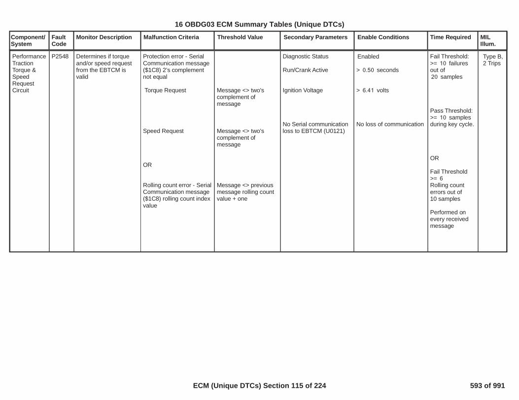
Component/System
FaultCode
Monitor Description Malfunction Criteria Threshold Value Secondary Parameters Enable Conditions Time Required MILIllum.
PerformanceTractionTorque &SpeedRequestCircuit
P2548 Determines if torqueand/or speed requestfrom the EBTCM isvalid
Protection error - SerialCommunication message($1C8) 2’s complementnot equal
Torque Request
Speed Request
OR
Rolling count error - SerialCommunication message($1C8) rolling count indexvalue
Message <> two'scomplement ofmessage
Message <> two'scomplement ofmessage
Message <> previousmessage rolling countvalue + one
Diagnostic Status
Run/Crank Active
Ignition Voltage
No Serial communicationloss to EBTCM (U0121)
Enabled
> seconds0.50
> volts6.41
No loss of communication
Fail Threshold:>= failures10out of
samples20
Pass Threshold:>= samples10during key cycle.
OR
Fail Threshold>= 6Rolling counterrors out of10 samples
Performed onevery receivedmessage
Type B,2 Trips
1
16 OBDG03 ECM Summary Tables (Unique DTCs)
ECM (Unique DTCs) Section 115 of 224 593 of 991

Component/System
FaultCode
Monitor Description Malfunction Criteria Threshold Value Secondary Parameters Enable Conditions Time Required MILIllum.
SENT FuelRailTemperatureSensor 1Circuit LowFault
P0182 This DTC diagnoseSENT fuel railtemperature sensor 1out of range low
Fuel Temperature Sensor1 SENT digital read value
< 145
No Fault Active on
No Fault Pending on
Fuel Temperature SensorOut of Range DiagnosticEnabled
Enabled when a codeclear is not active or notexiting device control
SENT CommunicationFault Active (P16E4,P16E5)
SENT Intenal Error FaultActive (P126E)
Fuel Temperature SensorSENT Message ErrorFault Active (P128C)
SENT Intenal Error FaultPending (P126E)
Fuel Temperature SensorSENT Message ErrorFault Pending (P128C)
50.00failures out of62.00samples100 ms perSampleContinuous
Type B,2 Trips
1
16 OBDG03 ECM Summary Tables (Unique DTCs)
ECM (Unique DTCs) Section 116 of 224 594 of 991

Component/System
FaultCode
Monitor Description Malfunction Criteria Threshold Value Secondary Parameters Enable Conditions Time Required MILIllum.
SENT FuelRailTemperatureSensor 1Circuit HighFault
P0183 This DTC diagnoseSENT fuel railtemperature sensor 1out of range high
Fuel Temperature Sensor1 SENT digital read value
> 1,865
No Fault Active on
No Fault Pending
Fuel Temperature SensorOut of Range DiagnosticEnabled
Enabled when a codeclear is not active or notexiting device control
SENT CommunicationFault Active (P16E4,P16E5)
SENT Intenal Error FaultActive (P126E)
Fuel Temperature SensorSENT Message ErrorFault Active (P128C)
SENT Intenal Error FaultPending (P126E)
Fuel Temperature SensorSENT Message ErrorFault Pending (P128C)
50.00failures out of62.00samples100 ms perSampleContinuous
Type B,2 Trips
2
16 OBDG03 ECM Summary Tables (Unique DTCs)
ECM (Unique DTCs) Section 117 of 224 595 of 991

Component/System
FaultCode
Monitor Description Malfunction Criteria Threshold Value Secondary Parameters Enable Conditions Time Required MILIllum.
SENT FuelRailTemperatureSensor 2Circuit LowFault
P0187 This DTC diagnoseSENT fuel railtemperature sensor 2out of range low
Fuel Temperature Sensor1 SENT digital read value
< 145.00
No Fault Active on
No Fault Pending
Fuel Temperature SensorOut of Range DiagnosticEnabled
Enabled when a codeclear is not active or notexiting device control
SENT CommunicationFault Active (P16E4,P16E5)
SENT Intenal Error FaultActive (P126F)
Fuel Temperature SensorSENT Message ErrorFault Active (P128D)
SENT Intenal Error FaultPending (P126F)
Fuel Temperature SensorSENT Message ErrorFault Pending (P128D)
50.00failures out of62.00samples100 ms perSampleContinuous
Type B,2 Trips
3
16 OBDG03 ECM Summary Tables (Unique DTCs)
ECM (Unique DTCs) Section 118 of 224 596 of 991

Component/System
FaultCode
Monitor Description Malfunction Criteria Threshold Value Secondary Parameters Enable Conditions Time Required MILIllum.
SENT FuelRailTemperatureSensor 2Circuit HighFault
P0188 This DTC diagnoseSENT fuel railtemperature sensor 2out of range low
Fuel Temperature Sensor1 SENT digital read value
> 1,865.00
No Fault Active on
No Fault Pending
Fuel Temperature SensorOut of Range DiagnosticEnabled
Enabled when a codeclear is not active or notexiting device control
SENT CommunicationFault Active (P16E4,P16E5)SENT Intenal Error FaultActive (P126F)
Fuel Temperature SensorSENT Message ErrorFault Active (P128D)
SENT Intenal Error FaultPending (P126F)
Fuel Temperature SensorSENT Message ErrorFault Pending (P128D)
50.00failures out of62.00samples100 ms perSampleContinuous
Type B,2 Trips
4
16 OBDG03 ECM Summary Tables (Unique DTCs)
ECM (Unique DTCs) Section 119 of 224 597 of 991

Component/System
FaultCode
Monitor Description Malfunction Criteria Threshold Value Secondary Parameters Enable Conditions Time Required MILIllum.
SIDI HighPressureSensorPerformance- DualSensor
P0191 The DTC Diagnoses askewed fuel rail sensor1 via a comparison ofsensor 2 continuouslywhen the engine isrunning and thecommanded pressureis steady
Primary sensor (P1) vs.Secondary sensor (P2)performance rationality
((Low Limit failFiltered Fuel ControlError )
OR
(High Limit Fail:Filtered Fuel ControlError))
AND
(FIltered Absolute deltabetween sensor1 andsensor2
<=P0191 -KtFHPD_cmp_DPS_FailLoThrsh (Dualsensors)(See supporting table)
>=P0191 -KtFHPD_cmp_DPS_FailHiThrsh (DualSensors)(see Supporting table)
>= mpa1.00
Note:fuel control error iscalcuated based on thesqureroot of senor1divided by sensor2,this value is filter toensure proper failuredetection.
Absolute deltabetween sensor1 andsensor2 value is filterto ensure proper failuredetection.
Commanded Pressurerate of change (increasingor dercresing)
for a period of time
Fuel pump temperature
Desired pressure
Dual SENT PressureSensor Equipped
SIDI High PressureSensor PerformanceDiagnostic Enabled
< mpa0.70
>= seconds1.25
<= degC1,000
>= mpa-1.00
Enabled when a codeclear is not active or notexiting device control
Filter FuelControl Errorterm andAbsolute deltabetween sensor1and sensor2exceed Low orHigh Fail limit fora duration >=
seconds1.50
This is diagnosticruns Continuous
Type A,1 Trips
5
16 OBDG03 ECM Summary Tables (Unique DTCs)
ECM (Unique DTCs) Section 120 of 224 598 of 991

Component/System
FaultCode
Monitor Description Malfunction Criteria Threshold Value Secondary Parameters Enable Conditions Time Required MILIllum.
Fuel LevelSensor 1Performance
(For use onvehicles witha single fueltank)
P0461 This DTC will detect afuel sender stuck inrange in the primaryfuel tank.
Delta fuel volume changeover liters of fuel20.6consumed by the engine.
< liters3 Engine Running
No active DTCs: VehicleSpeedSensor_FA
250 ms / sample Type B,2 Trips
6
16 OBDG03 ECM Summary Tables (Unique DTCs)
ECM (Unique DTCs) Section 121 of 224 599 of 991

Component/System
FaultCode
Monitor Description Malfunction Criteria Threshold Value Secondary Parameters Enable Conditions Time Required MILIllum.
Transmission OutputSpeedSensor(TOSS)
P0502 No activity in the TOSScircuit
TOSS Raw Speed RPM60 Engine Torque
Minimum Throttle opening
Engine Speed
Ignition voltage
PTO
EngineTorqureInaccurate
P0503
N-M 54.0 8,191.8
%8.0
RPM 1,500 6,500
Volts 9.0 32.00
not active
KeETQC_b_MinTransRemedial = TRUE:MSFR_b_EngMisfDtctd_FA,MAFR_b_MAF_SnsrTFTKO,MAPR_b_MAP_SnsrTFTKO
KeETQC_b_MinTransRemedial = FALSE:FULR_b_FuelInjCkt_TFTKO,MAFR_b_MAF_SnsrTFTKO, XOYR_b_SecurityFlt,
Not failed this key cycle
sec4.5 Type A,1 Trips
7
16 OBDG03 ECM Summary Tables (Unique DTCs)
ECM (Unique DTCs) Section 122 of 224 600 of 991

Component/System
FaultCode
Monitor Description Malfunction Criteria Threshold Value Secondary Parameters Enable Conditions Time Required MILIllum.
Transmission OutputSpeedSensor(TOSS)
P0503 TOSS SignalIntermittent
Loop-to-Loop change inTOSS
RPM350 Raw Output SpeedOutput
Speed changeTime sincetransfer case rangechange
Ignition voltage
Engine Speed
Vehicle Speed
PTO
> RPM for 300 2.0sec RPM for 150
sec2.0 sec6.0
Volts 9.0 32.00
RPM 200 7,500for seconds5.0
MPH for 511.99 5.0sec
not active
sec3.3 Type A,1 Trips
8
16 OBDG03 ECM Summary Tables (Unique DTCs)
ECM (Unique DTCs) Section 123 of 224 601 of 991

Component/System
FaultCode
Monitor Description Malfunction Criteria Threshold Value Secondary Parameters Enable Conditions Time Required MILIllum.
Clutch PedalPositionSensorCircuitRange /Performance
P0806 Detects if Clutch PedalPosition Sensor isStuck in a rangeindicative of a vehicleNOT in gear, when thevehicle is determined tobe in gear. Geardetermination is madeby verifying that theratio of engine RPMversus TransmissionOutput Speed (N/TOS)represents a valid gear.
Filtered Clutch PedalPosition Errorwhen the vehicle isdetermined to be in gear
> %4 N/TOS Ratio:
Transfer Case:
Vehicle speed:
Engine Torque:
Clutch Pedal Position:
OR
No Active DTCs:
Must match actual gear(i.e. vehicle in gear)
Not in 4WD Low range
> MPH4.3
>P0806EngTorqueThresholdTable(see Supporting Tables)
<P0806ResidualErrEnableLowTable(see Supporting Tables)>P0806ResidualErrEnableHighTable(see Supporting Tables)
ClutchPstnSnsrCktHi FAClutchPstnSnsrCktLo FACrankSensor_FATransmission OutputShaft Angular VelocityValidityVehicleSpeedSensor_FA
25 ms loopContinuous
Type A,1 Trips
9
16 OBDG03 ECM Summary Tables (Unique DTCs)
ECM (Unique DTCs) Section 124 of 224 602 of 991

Component/System
FaultCode
Monitor Description Malfunction Criteria Threshold Value Secondary Parameters Enable Conditions Time Required MILIllum.
Clutch PedalPositionSensorCircuit Low
P0807 Detects ContinuousCircuit Out-of-RangeLow or Open
Clutch Position SensorCircuit
for
< % of Vref4
counts out of200 250samples
Engine Not CrankingSystem Voltage > Volts9.0
25 ms loopContinuous
Type A,1 Trips
10
16 OBDG03 ECM Summary Tables (Unique DTCs)
ECM (Unique DTCs) Section 125 of 224 603 of 991

Component/System
FaultCode
Monitor Description Malfunction Criteria Threshold Value Secondary Parameters Enable Conditions Time Required MILIllum.
Clutch PedalPositionSensorCircuit High
P0808 Detects ContinuousCircuit Out-of-RangeHigh
Clutch Position SensorCircuit
for
> % of Vref96
counts out of200 250samples
Engine Not CrankingSystem Voltage > Volts9.0
25 ms loopContinuous
Type A,1 Trips
11
16 OBDG03 ECM Summary Tables (Unique DTCs)
ECM (Unique DTCs) Section 126 of 224 604 of 991
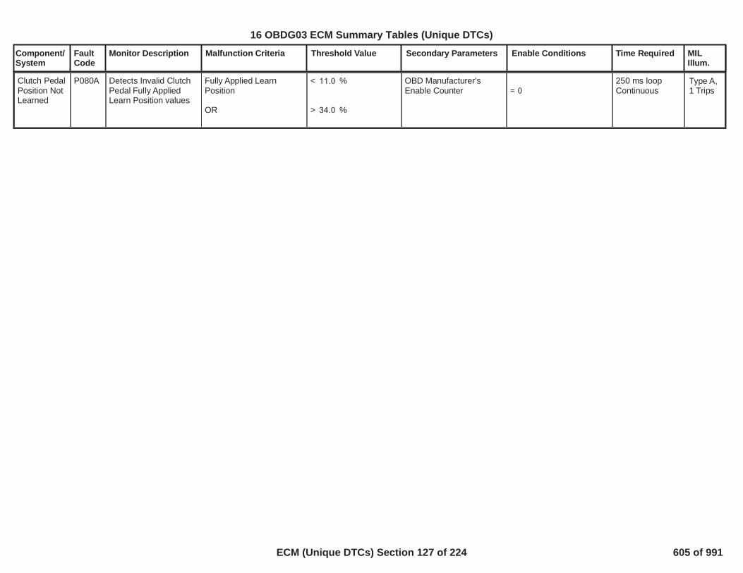
Component/System
FaultCode
Monitor Description Malfunction Criteria Threshold Value Secondary Parameters Enable Conditions Time Required MILIllum.
Clutch PedalPosition NotLearned
P080A Detects Invalid ClutchPedal Fully AppliedLearn Position values
Fully Applied LearnPosition
OR
< %11.0
> %34.0
OBD Manufacturer'sEnable Counter = 0
250 ms loopContinuous
Type A,1 Trips
12
16 OBDG03 ECM Summary Tables (Unique DTCs)
ECM (Unique DTCs) Section 127 of 224 605 of 991

Component/System
FaultCode
Monitor Description Malfunction Criteria Threshold Value Secondary Parameters Enable Conditions Time Required MILIllum.
SIDI HighPressureRailTemperatureSensorPerformance
P111F This DTC DiagnosesFuel Temperaturesensors rationality bycomparing Primarysensor (T1) vs.Secondary sensor (T2)
Fuel Temperature Error(Absolute delta betweensensor1 and sensor2)
> degC20.00
No Fault Active on
No Fault Pending on
Fuel Temperature SensorEquipped
SENT Fuel temperatureRationality DiagnosticsEnabled
Enabled when a codeclear is not active or notexiting device control
Temperature sensors 1out of range Low or HighFault Active (P0182,P0182)
Temperature sensors 2out of range Low or High(P0187, P0188)
SENT CommunicationFault Active (P16E4,P16E5)
SENT Intenal Error FaultActive (P126E, P126F)
Fuel Temperature SensorSENT Message ErrorFault Active (P128C,P128D)
SENT CommunicationFault Pending (P16E4,P16E5)
Fuel Temperature SensorSENT Message ErrorFault Pending (P128C,P128D)
100.00failures out of125.00samples
100 ms perSampleContinuous
Type B,2 Trips
13
16 OBDG03 ECM Summary Tables (Unique DTCs)
ECM (Unique DTCs) Section 128 of 224 606 of 991

Component/System
FaultCode
Monitor Description Malfunction Criteria Threshold Value Secondary Parameters Enable Conditions Time Required MILIllum.
SENT FuelRailTemperatureSensor 1Internal Fault- Error Code
P126E This DTC Diagnosesthe SENT FuelTemperature Sensor 1internal failure
Fuel Temperature Sensor1 SENT digital read value
>= 4,089.00
No Fault Active on
No Fault Pending on
Fuel Temperature SensorEquipped
Fuel temperature ErrorCode DIagnosticEnabled
Enabled when a codeclear is not active or notexiting device control
SENT CommunicationFault Active (P16E4,P16E5)
Fuel Temperature SensorSENT Message ErrorFault Active (P128C)
Fuel Temperature SensorSENT Message ErrorFault Pending (P128C)
50.00failures out of62.00samples
100 ms perSampleContinuous
Type B,2 Trips
14
16 OBDG03 ECM Summary Tables (Unique DTCs)
ECM (Unique DTCs) Section 129 of 224 607 of 991

Component/System
FaultCode
Monitor Description Malfunction Criteria Threshold Value Secondary Parameters Enable Conditions Time Required MILIllum.
SENT FuelRailTemperatureSensor 2Internal Fault- Error Code
P126F This DTC Diagnosesthe SENT FuelTemperature Sensor 2internal failure
Fuel Temperature Sensor2 SENT digital read value
>=4,089.00
No Fault Active on
No Fault Pending on
Fuel Temperature SensorEquipped
Fuel temperature ErrorCode DIagnosticEnabled
Enabled when a codeclear is not active or notexiting device control
SENT CommunicationFault Active (P16E4,P16E5)
Fuel Temperature SensorSENT Message Error(P128D)
Fuel Temperature SensorSENT Message ErrorFault Pending (P128D)
50.00failures out of62.00samples100 ms perSampleContinuous
Type B,2 Trips
15
16 OBDG03 ECM Summary Tables (Unique DTCs)
ECM (Unique DTCs) Section 130 of 224 608 of 991

Component/System
FaultCode
Monitor Description Malfunction Criteria Threshold Value Secondary Parameters Enable Conditions Time Required MILIllum.
SENT FuelRailPressureSensor 1InternalPerformance
P128A This DTC diagnosesthe internal error withinthe sensor (i.e. Brokenwire bond internal tothe SENT Sensor)
Digital pressure sesnor 1value
>= 4,089
Not Fault Pending
Enabled when a codeclear is not active or notexiting device control
SENT Fuel Rail PressureSensor InternalPerformance Enable
Dual SENT PressureSensor Equipped
P16E4P16E5P128F
Time BasedMode 400failures out of
samples5006.25 ms perSampleContinuous
Type A,1 Trips
16
16 OBDG03 ECM Summary Tables (Unique DTCs)
ECM (Unique DTCs) Section 131 of 224 609 of 991

Component/System
FaultCode
Monitor Description Malfunction Criteria Threshold Value Secondary Parameters Enable Conditions Time Required MILIllum.
SENT FuelRailPressureSensor 2InternalPerformance
P128B This DTC diagnosesthe internal error withinthe sensor (i.e. Brokenwire bond internal tothe SENT Sensor)
Digital pressure sesnor 2value
>= 4,089
Not Fault Pending
Enabled when a codeclear is not active or notexiting device control
SENT Fuel Rail PressureSensor InternalPerformance Enable
Dual SENT PressureSensor Equipped
P16E4P16E5P128F
Time BasedMode 400failures out of
samples5006.25 ms perSampleContinuous
Type A,1 Trips
17
16 OBDG03 ECM Summary Tables (Unique DTCs)
ECM (Unique DTCs) Section 132 of 224 610 of 991

Component/System
FaultCode
Monitor Description Malfunction Criteria Threshold Value Secondary Parameters Enable Conditions Time Required MILIllum.
SENT FuelRailPressure&Temperature SensorTemperature1 MessageIncorrect
P128C This DTC diagnosesthe the communicationerrors on thetemperature 1 serialdata channel
Type B,2 Trips
18
16 OBDG03 ECM Summary Tables (Unique DTCs)
ECM (Unique DTCs) Section 133 of 224 611 of 991

Component/System
FaultCode
Monitor Description Malfunction Criteria Threshold Value Secondary Parameters Enable Conditions Time Required MILIllum.
SENT FuelRailPressure &TemperatureSensorTemperature2 MessageIncorrect
P128D This DTC diagnosesthe the communicationerrors on thetemperature 2 serialdata channel
Type B,2 Trips
19
16 OBDG03 ECM Summary Tables (Unique DTCs)
ECM (Unique DTCs) Section 134 of 224 612 of 991

Component/System
FaultCode
Monitor Description Malfunction Criteria Threshold Value Secondary Parameters Enable Conditions Time Required MILIllum.
SENT FuelRailPressure &TemperatureSensorPressureMessageIncorrect
P128F This DTC diagnosesthe SENT signalwaveform fordiscrepancies (i.e. toomny pulse, too fewpulse, clock shift)
SENT HWIO Determinesmessage fault (i.e.toomny pulse, too few pulse,clock shift)
Message Age
= true
> ms1.94 SENT power up delay
No Fault Active on
Dual SENT PressureSensor Equipped
SENT signal waveformDiagnostics Enabled
>= seconds0.00
Enabled when a codeclear is not active or notexiting device control
P16E4P16E5
400failures out of500samples
6.5 ms persampleContinuous
Type A,1 Trips
20
16 OBDG03 ECM Summary Tables (Unique DTCs)
ECM (Unique DTCs) Section 135 of 224 613 of 991

Component/System
FaultCode
Monitor Description Malfunction Criteria Threshold Value Secondary Parameters Enable Conditions Time Required MILIllum.
SENT FuelRailPressure &TemperatureSensorCommunication Circuit 3Low Voltage
P16E4 This DTC diagnosesthe SENT signalshorted low
The number pulses on theSENT signal line
SENT Signal Line State
<= 35
= Low
SENT power up delay
Dual SENT PressureSensor Equipped
SENT SensorCommunication CircuitLow/High DiagnosticEnabled
>= seconds0.00
Enabled when a codeclear is not active or notexiting device control
400failures out of500samples
6.5 ms persampleContinuous
Type A,1 Trips
21
16 OBDG03 ECM Summary Tables (Unique DTCs)
ECM (Unique DTCs) Section 136 of 224 614 of 991

Component/System
FaultCode
Monitor Description Malfunction Criteria Threshold Value Secondary Parameters Enable Conditions Time Required MILIllum.
SENT FuelRailPressure &TemperatureSensorCommunication Circuit 3High Voltage
P16E5 This DTC diagnosesthe SENT signalshorted High
The number pulses on theSENT signal line
SENT Signal Line State
<= 35
= High
SENT power up delay
Dual SENT PressureSensor EquippedSENT SensorCommunication CircuitLow/High DiagnosticEnabled
>= seconds0.00
Enabled when a codeclear is not active or notexiting device control
400failures out of500samples
6.5 ms persample
Continuous
Type A,1 Trips
22
16 OBDG03 ECM Summary Tables (Unique DTCs)
ECM (Unique DTCs) Section 137 of 224 615 of 991

Component/System
FaultCode
Monitor Description Malfunction Criteria Threshold Value Secondary Parameters Enable Conditions Time Required MILIllum.
This function detects aserial communicationsfault based upon thedetection of missing orinvalid (receive) messagewithin the main processorbefore receiving a validmessage.
Run/Crank voltage >6.41
/39399countscontinuous; 12.5ms /count in theECM mainprocessor
ControlModuleSerialPeripheralInterfaceBus 1
P16F0 This DTC detectsintermitent andcontinuous invalid SPImessages.
Type A,1 Trips
This function detects aserial communicationsfault based upon thedetection of missing orinvalid (receive) messagewithin the main processorafter receiving a validmessage.
Run/Crank voltage >6.41
159/399
countscontinuous; 12.5ms /count in theECM mainprocessor
23
16 OBDG03 ECM Summary Tables (Unique DTCs)
ECM (Unique DTCs) Section 138 of 224 616 of 991

Component/System
FaultCode
Monitor Description Malfunction Criteria Threshold Value Secondary Parameters Enable Conditions Time Required MILIllum.
Mass AirFlow ASupplyVoltageControlCircuit
P121A Diagnoses the Mass AirFlow Power SupplyCircuit low side drivercircuit for circuit faults
Voltage low during driveroff state (indicates opencircuit)
Open Circuit: >= 200KOhms impedancebetween signal andcontroller ground
Mass Air Flow Power iscommanded on
Powertrain Relay Voltage >= Volts11.0
failures out40of samples50
1 sample every100 msec
Type B,2 Trips
Note: IncertaincontrollersP121Bmay alsoset(MassAir FlowA SupplyVoltageControlCircuitLow)
1
16 OBDG03 ECM Summary Tables (Unique DTCs)
ECM (Unique DTCs) Section 139 of 224 617 of 991

Component/System
FaultCode
Monitor Description Malfunction Criteria Threshold Value Secondary Parameters Enable Conditions Time Required MILIllum.
Mass AirFlow ASupplyVoltageControlCircuit Low
P121B Diagnoses the Mass AirFlow Power SupplyCircuit low side drivercircuit for circuit faults
Voltage low during driveroff state (indicates short-to-ground or open circuit)
Short to ground: <= 0.5Ohms impedancebetween signal andcontroller ground
Open Circuit: >= 200KOhms impedancebetween signal andcontroller ground
Mass Air Flow Power iscommanded on
Powertrain Relay Voltage >= Volts11.0
failures out40of samples50
1 sample every100 msec
Type B,2 Trips
Note: IncertaincontrollersP121Amay alsoset(MassAir FlowA SupplyVoltageControlCircuit)
2
16 OBDG03 ECM Summary Tables (Unique DTCs)
ECM (Unique DTCs) Section 140 of 224 618 of 991

Component/System
FaultCode
Monitor Description Malfunction Criteria Threshold Value Secondary Parameters Enable Conditions Time Required MILIllum.
Mass AirFlow ASupplyVoltageControlCircuit High
P121C Diagnoses the Mass AirFlow Power SupplyCircuit low side drivercircuit for circuit faults
Voltage low during driveron state (indicates short-to-power)
Short to power: <= 0.5Ohms impedancebetween signal andcontroller power
Mass Air Flow Power iscommanded off
Powertrain Relay Voltage >= Volts11.0
failures out40of samples50
1 sample every100 msec
Type B,2 Trips
3
16 OBDG03 ECM Summary Tables (Unique DTCs)
ECM (Unique DTCs) Section 141 of 224 619 of 991

Component/System
FaultCode
Monitor Description Malfunction Criteria Threshold Value Secondary Parameters Enable Conditions Time Required MILIllum.
HO2SHeaterResistanceBank 1Sensor 1
P0053 Detects an oxygensensor heater havingan incorrect or out ofrange resistance value.
Heater Resistanceoutside of the expectedrange of
< ohms <3.6 10.3 No Active DTC's
Coolant – IAT EngineSoak TimeCoolant TempIgnition VoltageEngine Run time
ECT_Sensor_FAP262BIAT_SensorFA< ºC8.0> seconds28,800
< ºC <-30.0 125.0< volts32.0< seconds0.05
Once per validcold start
Type B,2 Trips
1
16 OBDG03 ECM Summary Tables (Unique DTCs)
ECM (Unique DTCs) Section 142 of 224 620 of 991
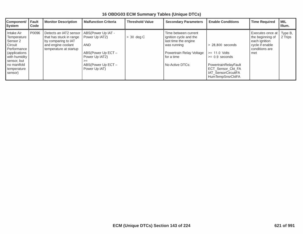
Component/System
FaultCode
Monitor Description Malfunction Criteria Threshold Value Secondary Parameters Enable Conditions Time Required MILIllum.
Intake AirTemperatureSensor 2CircuitPerformance(applicationswith humiditysensor, butno manifoldtemperaturesensor)
P0096 Detects an IAT2 sensorthat has stuck in rangeby comparing to IATand engine coolanttemperature at startup
ABS(Power Up IAT -Power Up IAT2)
AND
ABS(Power Up ECT –Power Up IAT2)>=ABS(Power Up ECT –Power Up IAT)
> deg C30Time between currentignition cycle and thelast time the enginewas running
Powertrain Relay Voltagefor a time
No Active DTCs:
> seconds28,800
>= Volts11.0>= seconds0.9
PowertrainRelayFaultECT_Sensor_Ckt_FAIAT_SensorCircuitFAHumTempSnsrCktFA
Executes once atthe beginning ofeach ignitioncycle if enableconditions aremet
Type B,2 Trips
2
16 OBDG03 ECM Summary Tables (Unique DTCs)
ECM (Unique DTCs) Section 143 of 224 621 of 991

Component/System
FaultCode
Monitor Description Malfunction Criteria Threshold Value Secondary Parameters Enable Conditions Time Required MILIllum.
RadiatorCoolantTempSensorCircuit LowVoltage
P00B3 This DTC detects ashort to ground in theRCT signal circuit orthe RCT sensor.
RCT Resistance(@ 150ºC)
< Ohms42 Engine run timeORIAT min
> seconds10.0
°C70.3
failures out of5samples10
1 sec/ sampleContinuous
Type B,2 Trips
3
16 OBDG03 ECM Summary Tables (Unique DTCs)
ECM (Unique DTCs) Section 144 of 224 622 of 991

Component/System
FaultCode
Monitor Description Malfunction Criteria Threshold Value Secondary Parameters Enable Conditions Time Required MILIllum.
RadiatorCoolantTempSensorCircuit HighVoltage
P00B4 Circuit ContinuityThis DTC detects ashort to high or open inthe RCT signal circuitor the RCT sensor.
RCT Resistance(@ -60ºC)
> Ohms320,000 Engine run timeORIAT min
> seconds60.0
°C-7.0
failures out of5samples10
1 sec/ sampleContinuous
Type B,2 Trips
4
16 OBDG03 ECM Summary Tables (Unique DTCs)
ECM (Unique DTCs) Section 145 of 224 623 of 991

Component/System
FaultCode
Monitor Description Malfunction Criteria Threshold Value Secondary Parameters Enable Conditions Time Required MILIllum.
EngineCoolant FlowInsufficient
P00B7 This DTC detects aInsufficient FlowCondition (i.e.. StuckClosed Thermostat)
Engine Coolant Temp(ECT) is greater than
Deg C and Difference117between ECT and RCT isgreater than Deg C.30When above is present formore than seconds, fail5counts start.
No Active DTC's
Engine run timeAND
Engine Coolant Temp
THMR_RCT_Sensor_Ckt_FATHMR_ECT_Sensor_Ckt_FA
> seconds300
> Deg C99.5
failures out of30samples60
1 sec/ sampleContinuous
Type B,2 Trips
5
16 OBDG03 ECM Summary Tables (Unique DTCs)
ECM (Unique DTCs) Section 146 of 224 624 of 991

Component/System
FaultCode
Monitor Description Malfunction Criteria Threshold Value Secondary Parameters Enable Conditions Time Required MILIllum.
Mass AirFlow SystemPerformance(naturallyaspirated)
P0101 Determines if the MAFsensor is stuck withinthe normal operatingrange
Filtered Throttle ModelErrorANDABS(Measured Flow –Modeled Air Flow) FilteredANDABS(Measured MAP –MAP Model 2) Filtered
<= kPa*(g/s)300
> grams/sec12.0
> kPa25.0
Engine SpeedEngine SpeedCoolant TempCoolant TempIntake Air TempIntake Air Temp
Minimum total weightfactor (all factorsmultiplied together)
See Residual WeightFactor tables.
No Active DTCs:-
>= RPM575<= RPM6,400>= Deg C-7<= Deg C129>= Deg C-20<= Deg C125
>= 0.50
Filtered Throttle ModelError multiplied byP0101, P0106, P0121,P012B, P0236, P1101:TPS Residual WeightFactor based on RPM
Modeled Air Flow Errormultiplied byP0101, P0106, P010B,P0121, P012B, P0236,P1101: MAF1 ResidualWeight Factor based onRPMandP0101, P0106, P010B,P0121, P012B, P0236,P1101: MAF1 ResidualWeight Factor based onMAF Est
MAP Model 2 Errormultiplied byP0101, P0106, P0121,P012B, P0236, P1101:MAP2 Residual WeightFactor based on RPM
MAP_SensorCircuitFA
Continuous
Calculation areperformed every12.5 msec
Type B,2 Trips
6
16 OBDG03 ECM Summary Tables (Unique DTCs)
ECM (Unique DTCs) Section 147 of 224 625 of 991

Component/System
FaultCode
Monitor Description Malfunction Criteria Threshold Value Secondary Parameters Enable Conditions Time Required MILIllum.
No Pending DTCs:
EGRValvePerformance_FAMAF_SensorCircuitFACrankSensor_FAECT_Sensor_FAIAT_SensorFA
EGRValve_FPECT_Sensor_Ckt_FPIAT_SensorCircuitFP
7
16 OBDG03 ECM Summary Tables (Unique DTCs)
ECM (Unique DTCs) Section 148 of 224 626 of 991

Component/System
FaultCode
Monitor Description Malfunction Criteria Threshold Value Secondary Parameters Enable Conditions Time Required MILIllum.
Filtered Throttle ModelErrorANDABS(Measured MAP –MAP Model 1) FilteredANDABS(Measured MAP –MAP Model 2) Filtered
<= kPa*(g/s)300
> kPa25.0
> kPa25.0
Engine SpeedEngine SpeedCoolant TempCoolant TempIntake Air TempIntake Air Temp
Minimum total weightfactor (all factorsmultiplied together)
See Residual WeightFactor tables.
No Active DTCs:
No Pending DTCs:
>= RPM575<= RPM6,400>= Deg C-7<= Deg C129>= Deg C-20<= Deg C125
>= 0.50
Filtered Throttle ModelError multiplied byP0101, P0106, P0121,P012B, P0236, P1101:TPS Residual WeightFactor based on RPM
MAP Model 1 Errormultiplied byP0101, P0106, P0121,P012B, P0236, P1101:MAP1 Residual WeightFactor based on RPM
MAP Model 2 Errormultiplied byP0101, P0106, P0121,P012B, P0236, P1101:MAP2 Residual WeightFactor based on RPM
MAP_SensorCircuitFAEGRValvePerformance_FAMAF_SensorCircuitFACrankSensor_FAECT_Sensor_FAIAT_SensorFA
EGRValve_FPECT_Sensor_Ckt_FP
Continuous
Calculations areperformed every12.5 msec
ManifoldAbsolutePressureSensorPerformance(naturallyaspirated)
P0106 Determines if the MAPsensor is stuck withinthe normal operatingrange
Type B,2 Trips
8
16 OBDG03 ECM Summary Tables (Unique DTCs)
ECM (Unique DTCs) Section 149 of 224 627 of 991

Component/System
FaultCode
Monitor Description Malfunction Criteria Threshold Value Secondary Parameters Enable Conditions Time Required MILIllum.
IAT_SensorCircuitFP
Manifold PressureORManifold Pressure
< kPa50.0
> kPa115.0
Time between currentignition cycle and the lasttime the engine wasrunning
Engine is not rotating
No Active DTCs:
No Pending DTCs:
> seconds409.6
EngineModeNotRunTimerErrorMAP_SensorCircuitFAAAP_SnsrCktFA
MAP_SensorCircuitFPAAP_SnsrCktFP
failures out999of samples5
1 sample every12.5 msec
9
16 OBDG03 ECM Summary Tables (Unique DTCs)
ECM (Unique DTCs) Section 150 of 224 628 of 991
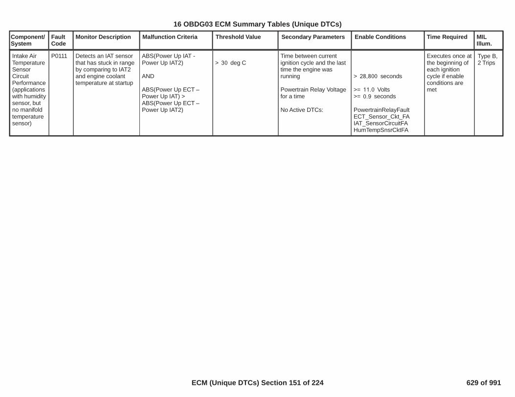
Component/System
FaultCode
Monitor Description Malfunction Criteria Threshold Value Secondary Parameters Enable Conditions Time Required MILIllum.
Intake AirTemperatureSensorCircuitPerformance(applicationswith humiditysensor, butno manifoldtemperaturesensor)
P0111 Detects an IAT sensorthat has stuck in rangeby comparing to IAT2and engine coolanttemperature at startup
ABS(Power Up IAT -Power Up IAT2)
AND
ABS(Power Up ECT –Power Up IAT) >ABS(Power Up ECT –Power Up IAT2)
> deg C30Time between currentignition cycle and the lasttime the engine wasrunning
Powertrain Relay Voltagefor a time
No Active DTCs:
> seconds28,800
>= Volts11.0>= seconds0.9
PowertrainRelayFaultECT_Sensor_Ckt_FAIAT_SensorCircuitFAHumTempSnsrCktFA
Executes once atthe beginning ofeach ignitioncycle if enableconditions aremet
Type B,2 Trips
10
16 OBDG03 ECM Summary Tables (Unique DTCs)
ECM (Unique DTCs) Section 151 of 224 629 of 991

Component/System
FaultCode
Monitor Description Malfunction Criteria Threshold Value Secondary Parameters Enable Conditions Time Required MILIllum.
ThrottlePositionSensorPerformance(naturallyaspirated)
P0121 Determines if theThrottle PositionSensor input is stuckwithin the normaloperating range
Filtered Throttle ModelErrorANDABS(Measured Flow –Modeled Air Flow) FilteredANDABS(Measured MAP –MAP Model 2) Filtered
> kPa*(g/s)300
> grams/sec12.0
<= kPa25.0
Engine SpeedEngine SpeedCoolant TempCoolant TempIntake Air TempIntake Air Temp
Minimum total weightfactor (all factorsmultiplied together)
See Residual WeightFactor tables.
No Active DTCs:
No Pending DTCs:
>= RPM575<= RPM6,400> Deg C-7< Deg C129> Deg C-20< Deg C125
>= 0.50
Filtered Throttle ModelError multiplied byP0101, P0106, P0121,P012B, P0236, P1101:TPS Residual WeightFactor based on RPM
Modeled Air Flow Errormultiplied byP0101, P0106, P010B,P0121, P012B, P0236,P1101: MAF1 ResidualWeight Factor based onRPMandP0101, P0106, P010B,P0121, P012B, P0236,P1101: MAF1 ResidualWeight Factor based onMAF Est
MAP_SensorCircuitFAEGRValvePerformance_FAMAF_SensorCircuitFACrankSensor_FAECT_Sensor_FAIAT_SensorFA
EGRValve_FP
Continuous
Calculation areperformed every12.5 msec
Type B,2 Trips
11
16 OBDG03 ECM Summary Tables (Unique DTCs)
ECM (Unique DTCs) Section 152 of 224 630 of 991
Component/System
FaultCode
Monitor Description Malfunction Criteria Threshold Value Secondary Parameters Enable Conditions Time Required MILIllum.
ECT_Sensor_Ckt_FPIAT_SensorCircuitFP
12
16 OBDG03 ECM Summary Tables (Unique DTCs)
ECM (Unique DTCs) Section 153 of 224 631 of 991

Component/System
FaultCode
Monitor Description Malfunction Criteria Threshold Value Secondary Parameters Enable Conditions Time Required MILIllum.
O2S CircuitLow VoltageBank 1Sensor 1
P0131 This DTC determines ifthe O2 sensor circuit isshorted to low.
Oxygen Sensor Signal < mVolts40.0 No Active DTC's
AIR intrusive testFuel intrusive testIdle intrusive testEGR intrusive testSystem VoltageEGR Device ControlIdle Device ControlFuel Device ControlAIR Device ControlLow Fuel Condition DiagEquivalence RatioAir Per CylinderFuel Control StateClosed Loop Active
All Fuel Injectors foractive CylindersFuel ConditionFuel State
TPS_ThrottleAuthorityDefaultedMAP_SensorFAAIR System FAEthanol CompositionSensor FAEvapPurgeSolenoidCircuit_FAEvapFlowDuringNonPurge_FAEvapVentSolenoidCircuit_FAEvapSmallLeak_FAEvapEmissionSystem_FAFuelTankPressureSnsrCkt_FAFuelInjectorCircuit_FA= Not active= Not active= Not active= Not active> Volts10.0= Not active= Not active= Not active= Not active= False
< ratio <0.9912 1.0098< mgram <120 500
= Closed Loop= TRUE(Please see “ClosedLoop EnableClarification” inSupporting Tables).
Enabled (On)Ethanol <= %87DFCO not active
failures out285of samples350
Frequency:Continuous in100 milli -second loop
Type B,2 Trips
13
16 OBDG03 ECM Summary Tables (Unique DTCs)
ECM (Unique DTCs) Section 154 of 224 632 of 991

Component/System
FaultCode
Monitor Description Malfunction Criteria Threshold Value Secondary Parameters Enable Conditions Time Required MILIllum.
All of the above met for > seconds5.0
14
16 OBDG03 ECM Summary Tables (Unique DTCs)
ECM (Unique DTCs) Section 155 of 224 633 of 991

Component/System
FaultCode
Monitor Description Malfunction Criteria Threshold Value Secondary Parameters Enable Conditions Time Required MILIllum.
O2S CircuitHigh VoltageBank 1Sensor 1
P0132 This DTC determines ifthe O2 sensor circuit isshorted to high.
Oxygen Sensor Signal > mvolts1,050 No Active DTC's
System VoltageAFM StatusHeater Warm-up delayEngine Run TimeEngine Run Accum
Low Fuel Condition Diag
Initial delay after OpenTest Criteria met (coldstart condition)
Initial delay after OpenTest Criteria met (not coldstart condition)
Equivalence Ratio
All of the above met for
TPS_ThrottleAuthorityDefaultedMAF_SensorFAMAP_SensorFAEvapExcessPurgePsbl_FAFuelInjectorCircuit_FAEthanol CompositionSensor FAAIR System FA
> Volts10.0= All Cylinders active= Complete> seconds5.0> seconds30.0
= False
> seconds when45.0engine soak time >
seconds28,800
> seconds when45.0engine soak time <=
seconds28,800
<=ratio<=0.9912 1.0098
> seconds5.0
failures out100of samples125
Frequency:Continuous in100 milli -second loop
Type B,2 Trips
15
16 OBDG03 ECM Summary Tables (Unique DTCs)
ECM (Unique DTCs) Section 156 of 224 634 of 991

Component/System
FaultCode
Monitor Description Malfunction Criteria Threshold Value Secondary Parameters Enable Conditions Time Required MILIllum.
O2S SlowResponseBank 1Sensor 1)(For use withESPD andw/o WRAF
P0133 This DTC determines ifthe O2 sensorresponse time isdegraded.
Fault condition presentwhen the averageresponse time iscaluclated over the testtime, and compared to thethreshold.
OR
Slope Time L/R Switches
OR
Slope Time R/L Switches
Refer to
in
P0133_O2S SlowResponse Bank 1Sensor 1 "Pass/FailThreshold table"the Supporting Tablestab
< 5
< 5
The test averages thesignal response timeover seconds60.0when the signal istransitioning between
mvolts and325 600mvolts. An averagerich to lean time andlean to rich time areeach calculatedseparately.
No Active DTC's
Bank 1 Sensor 1DTC's not active
System VoltageEGR Device ControlIdle Device ControlFuel Device ControlAIR Device ControlLow Fuel Condition DiagGreen O2S Condition
TPS_ThrottleAuthorityDefaultedMAP_SensorFAIAT_SensorFAECT_Sensor_FAAmbientAirDefaultMAF_SensorFAEvapPurgeSolenoidCircuit_FAEvapFlowDuringNonPurge_FAEvapVentSolenoidCircuit_FAEvapSmallLeak_FAEvapEmissionSystem_FAFuelTankPressureSnsrCkt_FAFuelInjectorCircuit_FAAIR System FAEthanol CompositionSensor FAEngineMisfireDetected_FA
P0131, P0132, P0134
> Volts10.0= Not active= Not active= Not active= Not active= False= Not Valid, See definitionofMultiple DTC Use_GreenSensor Delay Criteria -AirflowandMultiple DTC Use_GreenSensor Delay Criteria -Limit
Sample time isseconds60
Frequency:Once per trip
Type B,2 Trips
16 OBDG03 ECM Summary Tables (Unique DTCs)
ECM (Unique DTCs) Section 157 of 224 635 of 991

Component/System
FaultCode
Monitor Description Malfunction Criteria Threshold Value Secondary Parameters Enable Conditions Time Required MILIllum.
O2 Heater on forLearned Htr resistance
Engine CoolantIATEngine run Accum
Time since any AFMstatus changeTime since Purge On toOff changeTime since Purge Off toOn change
Engine airflowEngine speedFuel ConditionBaroAir Per Cylinder
Fuel Control StateClosed Loop Active
LTM (Block Learn) fuelcell
Transient Fuel Mass
for the following locations:B1S1, B2S1 (if applicable)in Supporting Tables tab.
>= seconds40= Valid ( the heaterresistance has learnedsince NVM reset, seeenable conditions for"HO2S Heater ResistanceDTC's" )> ºC62> ºC-40> seconds30
> seconds2.0
> seconds0.0
> seconds1.5
<=grams/second<=10 40<= RPM <=1,000 3,500
< % Ethanol87> kpa70>= mGrams200
= Closed Loop= TRUE(Please see “ClosedLoop EnableClarification” inSupporting Tables).
= Enabled, refer toMultiple DTC Use -Response Cell EnableTablefor additional info.
<= mgrams100.0
16 OBDG03 ECM Summary Tables (Unique DTCs)
ECM (Unique DTCs) Section 158 of 224 636 of 991

Component/System
FaultCode
Monitor Description Malfunction Criteria Threshold Value Secondary Parameters Enable Conditions Time Required MILIllum.
BaroFuel Control StateFuel StateCommanded ProportionalGain
==================All of the above met for
= Not Defaultednot = Power EnrichmentDFCO not active
>= %0.0
==================> seconds3.0
16 OBDG03 ECM Summary Tables (Unique DTCs)
ECM (Unique DTCs) Section 159 of 224 637 of 991

Component/System
FaultCode
Monitor Description Malfunction Criteria Threshold Value Secondary Parameters Enable Conditions Time Required MILIllum.
O2 SensorDelayedResponseRich to LeanBank 1Sensor 1)(For use w/oWRAF
P015A This DTC determines ifthe pre catalyst O2sensor has an initialdelayed response to anA/F change from Richto Lean. The diagnosticis an intrusive testwhich runs in a DFCOmode to achieve therequired response.
The EWMA of the Pre O2sensor normalized R2Ltime delay value. TheEWMA caluclation uses a
coefficient.0.25
OR
[The Accumulated timemonitored during the R2LDelayed Response Test(Gross failure).
AND
Pre O2 sensor voltage is
> EWMA (sec)0.5
>= Seconds1.5
> mvolts550
No Active DTC's
System VoltageEGR Device ControlIdle Device ControlFuel Device ControlAIR Device ControlLow Fuel Condition Diag
Green O2S Condition
TPS_ThrottleAuthorityDefaultedECT_Sensor_FAIAT_SensorFAMAF_SensorFAMAP_SensorFAAIR System FAFuelInjectorCircuit_FAFuelTrimSystemB1_FAFuelTrimSystemB2_FAEngineMisfireDetected_FAEthanol CompositionSensor FAEvapPurgeSolenoidCircuit_FAEvapFlowDuringNonPurge_FAEvapVentSolenoidCircuit_FAEvapSmallLeak_FAEvapEmissionSystem_FAFuelTankPressureSnsrCkt_FAAmbientAirDefault
P0131, P0132, P013A,P013B, P013E, P013F,P2270, P2271
> Volts10.0= Not active= Not active= Not active= Not active= False
= Not Valid, See definitionof
Frequency:Once per tripNote: ifNaESPD_b_FastInitRespIsActive= TRUE for thegiven Fuel BankORNaESPD_b_RapidResponseIsActive = TRUE,multiple tests pertrip are allowed
Type A,1 TripsEWMA
19
16 OBDG03 ECM Summary Tables (Unique DTCs)
ECM (Unique DTCs) Section 160 of 224 638 of 991

Component/System
FaultCode
Monitor Description Malfunction Criteria Threshold Value Secondary Parameters Enable Conditions Time Required MILIllum.
O2 Heater (pre sensor) onLearned Htr resistance
Engine CoolantIATEngine run Accum
Engine Speed to initiallyenable testEngine Speed range tokeep test enabled (afterinitially enabled)
Engine AirflowVehicle Speed to initiallyenable testVehicle Speed range tokeep test enabled (afterinitially enabled)
Closed loop integralClosed Loop Active
Multiple DTC Use_GreenSensor Delay Criteria -AirflowandMultiple DTC Use_GreenSensor Delay Criteria -Limitfor the following locations:B1S1, B2S1 (if applicable)in Supporting Tables tab.
>= seconds40= Valid ( the heaterresistance has learnedsince NVM reset, seeenable conditions for"HO2S Heater ResistanceDTC's" )
> ºC62> ºC-40> seconds30
<= RPM <=1,250 2,600
<= RPM <=1,100 2,750
<= gps <=3 11
<= MPH <=34.2 74.6
<= MPH <=31.7 82.0
<= C/L Int <=0.85 1.07= TRUE(Please see “ClosedLoop Enable
20
16 OBDG03 ECM Summary Tables (Unique DTCs)
ECM (Unique DTCs) Section 161 of 224 639 of 991

Component/System
FaultCode
Monitor Description Malfunction Criteria Threshold Value Secondary Parameters Enable Conditions Time Required MILIllum.
EvapEthanolBaroPost fuel cell
EGR Intrusive diagnosticAll post sensor heaterdelaysO2S Heater (post sensor)on TimePredicted Catalyst tempFuel State
===================All of the above met for atleast seconds, and3.0then the Force Cat Richintrusive stage isrequested.===================
Pre O2S voltage B1S1 atend of Cat Rich stageFuel StateNumber of fueledcylinders
===================After above conditions aremet: DFCO Mode isentered (wo driverinitiated pedal input).
Clarification” inSupporting Tables).
not in control of purgenot in estimate mode> kpa70= enabled
= not active
= not active
>= sec60.0<= ºC <=600 850
= DFCO possible
==================
==================
>= mvolts690= DFCO active
<= cylinders3
==================
21
16 OBDG03 ECM Summary Tables (Unique DTCs)
ECM (Unique DTCs) Section 162 of 224 640 of 991

Component/System
FaultCode
Monitor Description Malfunction Criteria Threshold Value Secondary Parameters Enable Conditions Time Required MILIllum.
O2 SensorDelayedResponseLean to RichBank 1Sensor 1)(For use w/oWRAF
P015B This DTC determines ifthe pre catalyst O2sensor has an initialdelayed response to anA/F change from Leanto Rich. The diagnosticis an intrusive testwhich runs in anenriched fuel mode toachieve the requiredresponse.
The EWMA of the Pre O2sensor normalized L2Rtime delay value. TheEWMA caluclation uses a
coefficient.0.25
OR
[The Accumulated timemonitored during the L2RDelayed Response Test(Gross failure).
AND
Pre O2 sensor voltage is
OR
At end of Cat Rich stagethe Pre O2 sensor outputis
> EWMA (sec)0.5
>= Seconds1.5
< mvolts350
< mvolts690
No Active DTC's
P015A test is completeand
System VoltageEGR Device ControlIdle Device ControlFuel Device ControlAIR Device ControlLow Fuel Condition Diag
Green O2S Condition
TPS_ThrottleAuthorityDefaultedECT_Sensor_FAIAT_SensorFAMAF_SensorFAMAP_SensorFAAIR System FAFuelInjectorCircuit_FAFuelTrimSystemB1_FAFuelTrimSystemB2_FAEngineMisfireDetected_FAEthanol CompositionSensor FAEvapPurgeSolenoidCircuit_FAEvapFlowDuringNonPurge_FAEvapVentSolenoidCircuit_FAEvapSmallLeak_FAEvapEmissionSystem_FAFuelTankPressureSnsrCkt_FAAmbientAirDefault
P0131, P0132, P013A,P013B, P013E, P013F,P015A, P2270, P2271
= Passed
> Volts10.0= Not active= Not active= Not active= Not active= False
= Not Valid, See definitionof
Frequency:Once per tripNote: ifNaESPD_b_FastInitRespIsActive= TRUE for thegiven Fuel BankORNaESPD_b_RapidResponseIsActive = TRUE,multiple tests pertrip are allowed
Type A,1 TripsEWMA
22
16 OBDG03 ECM Summary Tables (Unique DTCs)
ECM (Unique DTCs) Section 163 of 224 641 of 991
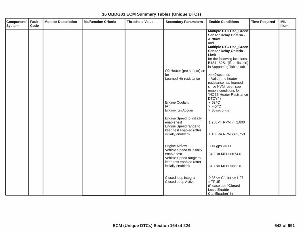
Component/System
FaultCode
Monitor Description Malfunction Criteria Threshold Value Secondary Parameters Enable Conditions Time Required MILIllum.
O2 Heater (pre sensor) onforLearned Htr resistance
Engine CoolantIATEngine run Accum
Engine Speed to initiallyenable testEngine Speed range tokeep test enabled (afterinitially enabled)
Engine AirflowVehicle Speed to initiallyenable testVehicle Speed range tokeep test enabled (afterinitially enabled)
Closed loop integralClosed Loop Active
Multiple DTC Use_GreenSensor Delay Criteria -AirflowandMultiple DTC Use_GreenSensor Delay Criteria -Limitfor the following locations:B1S1, B2S1 (if applicable)in Supporting Tables tab.
>= seconds40= Valid ( the heaterresistance has learnedsince NVM reset, seeenable conditions for"HO2S Heater ResistanceDTC's" )> ºC62> ºC-40> seconds30
<= RPM <=1,250 2,600
<= RPM <=1,100 2,750
<= gps <=3 11
<= MPH <=34.2 74.6
<= MPH <=31.7 82.0
<= C/L Int <=0.85 1.07= TRUE(Please see “ClosedLoop EnableClarification” in
23
16 OBDG03 ECM Summary Tables (Unique DTCs)
ECM (Unique DTCs) Section 164 of 224 642 of 991

Component/System
FaultCode
Monitor Description Malfunction Criteria Threshold Value Secondary Parameters Enable Conditions Time Required MILIllum.
EvapEthanolBaroPost fuel cellEGR Intrusive diagnosticAll post sensor heaterdelaysO2S Heater (post sensor)on Time
Predicted Catalyst tempFuel StateNumber of fueledcylinders
================When above conditionsare met: Fuel Enrichmode is entered.
================
During this test: EngineAirflow must staybetween:and the delta EngineAirflow over 12.5msecmust be :
Supporting Tables).
not in control of purgenot in estimate mode> kpa70= enabled= not active
= not active
>= sec60.0
<= ºC <=600 850= DFCO inhibit
>= cylinders1
==================
==================
<= gps <=0 10
<= gps5.0
24
16 OBDG03 ECM Summary Tables (Unique DTCs)
ECM (Unique DTCs) Section 165 of 224 643 of 991

Component/System
FaultCode
Monitor Description Malfunction Criteria Threshold Value Secondary Parameters Enable Conditions Time Required MILIllum.
ThermostatHeaterControlOpen Circuit
P0597 Diagnoses the T-statHeater low side drivercircuit for circuit faults.
Voltage low during driveroff state (indicates opencircuit)
Open Circuit: 200 K impedance
between signal andcontroller ground.
Run Crank Ignition inRange
Engine not crankingRun Crank active
== Above is true and ==
Last Open Circuit Test
= True
= True= True
===================
= not Indeterminate
failures out of15samples30
1 sec/ sample
Continuous
Type B,2 TripsNote: Incertiancontrollers P0598may alsoset
25
16 OBDG03 ECM Summary Tables (Unique DTCs)
ECM (Unique DTCs) Section 166 of 224 644 of 991

Component/System
FaultCode
Monitor Description Malfunction Criteria Threshold Value Secondary Parameters Enable Conditions Time Required MILIllum.
ThermostatHeaterControlCircuit Low
P0598 Diagnoses the T-statHeater low side drivercircuit for circuit faults.
Voltage low during driveroff state (indicates short-to-ground)
Short to ground: 0.5 impedance
between signal andcontroller ground
Run Crank Ignition inRange
Engine not crankingRun Crank active
== Above is true and ==
Last Ground Short CircuitTest
= True
= True= True
================
= not Indeterminate
failures out of15samples30
1 sec/ sample
Continuous
Type B,2 TripsNote: Incertiancontrollers P0597may alsoset
26
16 OBDG03 ECM Summary Tables (Unique DTCs)
ECM (Unique DTCs) Section 167 of 224 645 of 991

Component/System
FaultCode
Monitor Description Malfunction Criteria Threshold Value Secondary Parameters Enable Conditions Time Required MILIllum.
ThermostatHeaterControlCircuit High
P0599 Diagnoses the T-statHeater low side drivercircuit for circuit faults.
Voltage high during driveron state (indicates shortto power)
Short to power: 0.5 impedance
between signal andcontroller power.
Run Crank Ignition inRange
Engine not crankingRun Crank active
== Above is true and ==
Last Power Short CircuitTest
= True
= True= True
==================
= not Indeterminate
failures out of15samples30
1 sec/ sample
Continuous
Type B,2 Trips
27
16 OBDG03 ECM Summary Tables (Unique DTCs)
ECM (Unique DTCs) Section 168 of 224 646 of 991

Component/System
FaultCode
Monitor Description Malfunction Criteria Threshold Value Secondary Parameters Enable Conditions Time Required MILIllum.
Inlet AirflowSystemPerformance(naturallyaspirated)
P1101 Determines if there aremultiple air inductionproblems affectingairflow and/or manifoldpressure.
Filtered Throttle ModelError
AND
ABS(Measured Flow –Modeled Air Flow) FilteredORABS(Measured MAP –MAP Model 1) Filtered
AND
ABS(Measured MAP –MAP Model 2) Filtered
<= kPa*(g/s)300
> grams/sec12.0
> kPa )25.0
> kPa25.0
Engine SpeedEngine SpeedCoolant TempCoolant TempIntake Air TempIntake Air Temp
Minimum total weightfactor (all factorsmultiplied together)
See Residual WeightFactor tables.
>= RPM575<= RPM6,400> Deg C-7< Deg C129> Deg C-20< Deg C125
>= 0.50
Filtered Throttle ModelError multiplied byP0101, P0106, P0121,P012B, P0236, P1101:TPS Residual WeightFactor based on RPM
Modeled Air Flow Errormultiplied byP0101, P0106, P010B,P0121, P012B, P0236,P1101: MAF1 ResidualWeight Factor based onRPMandP0101, P0106, P010B,P0121, P012B, P0236,P1101: MAF1 ResidualWeight Factor based onMAF Est
MAP Model 1 Errormultiplied byP0101, P0106, P0121,P012B, P0236, P1101:MAP1 Residual WeightFactor based on RPM
MAP Model 2 Errormultiplied by
Continuous
Calculation areperformed every12.5 msec
Type B,2 Trips
28
16 OBDG03 ECM Summary Tables (Unique DTCs)
ECM (Unique DTCs) Section 169 of 224 647 of 991

Component/System
FaultCode
Monitor Description Malfunction Criteria Threshold Value Secondary Parameters Enable Conditions Time Required MILIllum.
No Active DTCs:
No Pending DTCs:
P0101, P0106, P0121,P012B, P0236, P1101:MAP2 Residual WeightFactor based on RPM
MAP_SensorCircuitFAEGRValvePerformance_FAMAF_SensorCircuitFACrankSensor_FAECT_Sensor_FAIAT_SensorFA
EGRValve_FPECT_Sensor_Ckt_FPIAT_SensorCircuitFP
29
16 OBDG03 ECM Summary Tables (Unique DTCs)
ECM (Unique DTCs) Section 170 of 224 648 of 991

Component/System
FaultCode
Monitor Description Malfunction Criteria Threshold Value Secondary Parameters Enable Conditions Time Required MILIllum.
EngineCoolantTemperatureSensor NotPlausible)(TSRD
P111E This DTC detects adifference betweenECT and two othertemp sensors after asoak condition.
Sensor usagedefinitions:
Sensor1 =CeECTD_e_ECT_Snsr(Sensor1 is the tempsensor most impacted bythe block heater (ifequipped))
Sensor2 =CeECTD_e_RCT_Snsr
Sensor3 =CeECTD_e_IAT_Snsr
===================
A failure will be reported ifany of the following occur:
1) Sensor1 power upabsolute temp differenceto Sensor2 and Sensor3is(Sensor1 fast fail) .
2) Sensor1 power uptemp is greater thanSensor2 and Sensor3 inthis range:(and a block heater hasnot been detected)
3) Sensor1 power uptemp is lower thanSensor2 and Sensor3 bythis amount:
4) Sensor1 power uptemp is Sensor2 and
ºC60.0
and < ºC15.8 60.0
Deg ºC15.8
No Active DTC's
Engine Off Soak TimePropulsion Off Soak TimeNon-volatile memoryinitization
Test complete this tripTest aborted this tripTest disabled this tripAmbientLowFuelCondition Diag
==================Block Heater detection isenabled when either ofthe following occurs:
1) Sensor1 power uptemp is greater thanSensor2 and Sensor3 inthis range:
2) Cranking time
==================Block Heater is detected
VehicleSpeedSensor_FAIAT_SensorCircuitFATHMR_RCT_Sensor_Ckt_FAECT_Sensor_Ckt_FAEngineModeNotRunTimerErrorEngineModeNotRunTimer_FAOAT_PtEstFiltFAOAT_PtEstRawFAPSAR_PropSysInactveCrs_FADRER_DiagSystemDsbl
> seconds25,200> seconds0
= Not occurred
= False= False= False ºC-7
= False
==================
ºC and <15.8ºC60.0
< Seconds10.0
==================
1 failure to setDTC
1 sec/ sample
Once per validcold start
Type B,2 Trips
30
16 OBDG03 ECM Summary Tables (Unique DTCs)
ECM (Unique DTCs) Section 171 of 224 649 of 991

Component/System
FaultCode
Monitor Description Malfunction Criteria Threshold Value Secondary Parameters Enable Conditions Time Required MILIllum.
Sensor3 by ºC and15.8the time spent crankingthe engine without startingis seconds with the10.0LowFuelConditionDiag = False
and diagnostic is abortedwhen 1) or 2) occurs.
1a) IAT monitoring isenabled after the followingVehicle drive constraints1b) Drive time
1c) Vehicle speed
1d) Additional Vehicledrive time is provided to1b when Vehicle speed isbelow 1c as follows:
1e) IAT drops from powerup IAT
2a) ECT monitoring isenabled after engine startin the following engine runtime window
2b) Sensor1 tempderivative during the testis:
2c) Consectutive samplesof 2b) being true are:
==================Diagnostic is abortedwhen 3) or 4) occurs:
3) Engine run time withvehicle speed below 1b
4) Engine off time (i.e.auto stop) during Blockheater detection
> Seconds with400
> MPH and14.9
times the seconds0.50with vehicle speed below1b
ºC5.0
<= seconds <=5.0 60.0
< ºC/sec-0.10
samples4
===================
Seconds1,800
Seconds180.0
31
16 OBDG03 ECM Summary Tables (Unique DTCs)
ECM (Unique DTCs) Section 172 of 224 650 of 991

Component/System
FaultCode
Monitor Description Malfunction Criteria Threshold Value Secondary Parameters Enable Conditions Time Required MILIllum.
RadiatorCoolantTemperatureSensor NotPlausible)(TSRD
P112F This DTC detects adifference betweenRCT and two othertemp sensors after asoak condition.
Sensor usagedefinitions:
Sensor1 =CeECTD_e_ECT_Snsr(Sensor1 is the tempsensor most impacted bythe block heater (ifequipped))
Sensor2 =CeECTD_e_RCT_Snsr
Sensor3 =CeECTD_e_IAT_Snsr
===================
A failure will be reported if(based on the abovecalibrations):
1) Sensor2 (if RCT isSensor2 )power upabsolute temp differenceto Sensor1 and Sensor3is:
OR (based on usage)
2) Sensor3 (if RCT isSensor3) power upabsolute temp differenceto Sensor1 and Sensor2is:
ºC15.8
ºC15.8
No Active DTC's
Engine Off Soak TimePropulsion Off Soak TimeNon-volatile memoryinitization
Test complete this tripTest aborted this tripTest disabled this tripAmbientLowFuelCondition Diag
VehicleSpeedSensor_FAIAT_SensorCircuitFATHMR_RCT_Sensor_Ckt_FAECT_Sensor_Ckt_FAEngineModeNotRunTimerErrorEngineModeNotRunTimer_FAOAT_PtEstFiltFAOAT_PtEstRawFAPSAR_PropSysInactveCrs_FADRER_DiagSystemDsbl
> seconds25,200> seconds0
= Not occurred
= False= False= False ºC-7
= False
1 failure to setDTC
1 sec/ sample
Once per validcold start
Type B,2 Trips
32
16 OBDG03 ECM Summary Tables (Unique DTCs)
ECM (Unique DTCs) Section 173 of 224 651 of 991

Component/System
FaultCode
Monitor Description Malfunction Criteria Threshold Value Secondary Parameters Enable Conditions Time Required MILIllum.
TransferCase SpeedSensorOutput(TCSS)
P2160 No activity in the TCSSSignal circuit
TCSS Raw Speed RPM50 Engine Torque
Throttle Position
Transmission gear
Garage Shift
PTO
EngineTorqureInaccurate
N-M 60.0 8,191.8
% 8 99
Not in Park or Neutral
Not active
Not activeNot a hybrid vehicle
FALSE
sec5.0 Type B,2 Trips
33
16 OBDG03 ECM Summary Tables (Unique DTCs)
ECM (Unique DTCs) Section 174 of 224 652 of 991

Component/System
FaultCode
Monitor Description Malfunction Criteria Threshold Value Secondary Parameters Enable Conditions Time Required MILIllum.
TransferCase SpeedSensorOutput(TCSS)
P2161 TCSS Circuit SignalIntermittent
TCSS Loop-to-Loopspeed decreaseORTCSS Loop-to-Loopspeed increase
RPM475
RPM225
Engine Speed
TCSS Speed
Transmission gear
Garage Shift
PTO
P2160
RPM1,000
> 0
Not in Park or Neutral
Not active
Not active
CrankSensor_FA =FALSE
Not Fault Active
sec4.0 Type B,2 Trips
34
16 OBDG03 ECM Summary Tables (Unique DTCs)
ECM (Unique DTCs) Section 175 of 224 653 of 991

Component/System
FaultCode
Monitor Description Malfunction Criteria Threshold Value Secondary Parameters Enable Conditions Time Required MILIllum.
CoolingSystemPerformance
P2181 This DTC detectsthermostat malfunction(i.e. stuck open)
This diagnostic can becalibrated to fail in one oftwo methods based onthe following calibration.This application has beencalibrated as a Type .1
Type 0 - Airflow Method:Engine Coolant Temp(ECT) is commandedtemperature minus 18Deg C and normalizedratio is than .0.00When above is present formore than seconds, fail5counts start.== Ratio Definition:===Current temp differencebetween ECT and RCTminus PwrUp differencedivided by total airgrams.Note: Minimum totalairgrams is grams.100.0
Type 1 - Energy Method:Engine Coolant Temp(ECT) is commandedtemperature minus 18Deg C and normalizedratio is than .1.10When above is present formore than seconds, fail5counts start.== Ratio Definition:===Current temp differencebetween ECT and RCTminus PwrUp differencedivided by predictedenergy.
No Active DTC's
Engine not run time
Engine run time
Fuel ConditionECT at Power UpIAT minT-Stat Heater duty cyclecommanded
Type 0: Airflow range toaccumulate
Type 1: Minumum energyto enable
MAF_SensorFAIAT_SensorFATHMR_RCT_Sensor_Ckt_FATHMR_ECT_Sensor_Ckt_FATHMR_AHV_FA
seconds25,200
Time 90 1,800seconds
Ethanol %87 ECT °C-10.0 75.0
°C IAT °C.-7 52
%20
Airflow gps8.0 30.0
kJ500.0
failures out of30samples90
1 sec/ sample
Once per ignitionkey cycle
Type B,2 Trips
35
16 OBDG03 ECM Summary Tables (Unique DTCs)
ECM (Unique DTCs) Section 176 of 224 654 of 991

Component/System
FaultCode
Monitor Description Malfunction Criteria Threshold Value Secondary Parameters Enable Conditions Time Required MILIllum.
Difference between barosensor reading andestimated barowhen distance since lastestimated baro update
OR
Difference between barosensor reading andestimated barowhen distance since lastestimated baro update
> kPa15.0
<= miles1.24
> kPa20.0
> miles1.24
No Active DTCs: AmbPresSnsrCktFAECT_Sensor_Ckt_FAIAT_SensorFAMAF_SensorFAAfterThrottlePressureFATPS_FATPS_Performance_FAVehicleSpeedSensor_FA
failures out320of samples400
1 sample every12.5 msec
BarometricPressure(BARO)SensorPerformance(naturallyaspirated)
P2227 Compares baro sensorto the calculated baroestimate (part throttlecalculation orunthrottled MAP)
Type B,2 Trips
Barometric PressureORBarometric Pressure
< kPa50.0
> kPa115.0
Time between currentignition cycle and the lasttime the engine wasrunning
Engine is not rotating
No Active DTCs:
No Pending DTCs:
> seconds409.6
EngineModeNotRunTimerErrorMAP_SensorCircuitFAAAP_SnsrCktFA
MAP_SensorCircuitFPAAP_SnsrCktFP
failures out999of samples5
1 sample every12.5 msec
36
16 OBDG03 ECM Summary Tables (Unique DTCs)
ECM (Unique DTCs) Section 177 of 224 655 of 991

Component/System
FaultCode
Monitor Description Malfunction Criteria Threshold Value Secondary Parameters Enable Conditions Time Required MILIllum.
BarometricPressure(BARO)SensorCircuit Low(non-boostedapplications,Gen III)
P2228 Detects a continuousshort to low in eitherthe signal circuit or theBARO sensor.
BARO Voltage < % of 5 Volt40.0Range( Volts = kPa)2.0 50.9
failures out320of samples400
1 sample every12.5 msec
Type B,2 Trips
37
16 OBDG03 ECM Summary Tables (Unique DTCs)
ECM (Unique DTCs) Section 178 of 224 656 of 991

Component/System
FaultCode
Monitor Description Malfunction Criteria Threshold Value Secondary Parameters Enable Conditions Time Required MILIllum.
BarometricPressure(BARO)SensorCircuit High(non-boostedapplications,Gen III)
P2229 Detects an opensensor ground,continuous short tohigh or open in eitherthe signal circuit or theBARO sensor.
BARO Voltage > % of 5 Volt90.0Range( Volts =4.5 115.0kPa)
failures out320of samples400
1 sample every12.5 msec
Type B,2 Trips
38
16 OBDG03 ECM Summary Tables (Unique DTCs)
ECM (Unique DTCs) Section 179 of 224 657 of 991

Component/System
FaultCode
Monitor Description Malfunction Criteria Threshold Value Secondary Parameters Enable Conditions Time Required MILIllum.
Four WheelDrive LowSwitchCircuit
P2771 Fail Case 1:Continuous Open(Stuck Off) in the FourWheel Drive LowSwitch CircuitFail Case2: Ground (Stuck On)in the Four Wheel DriveLow Switch Circuit
4WD Low SwitchTransfer case gear ratio
4WD Low SwitchTransfer case gear ratio
= TRUEand5.700 8.000
= FALSEand0.700 1.550
Engine Torque
Engine Speed
Ignition voltage
Throttle position
TransmissionTemperature
Engine Run time
Vehicle Speed
TPS_FAVehicleSpeedSensor_FA
EngineTorqureInaccurate
Transmission gear
P0502, P0503, P0722,P0723, P215C, P2160,P2161, U0101
Clutch
Transmission Input SpeedSignal
N-M 30.0 8,191.8
RPM 1,000 5,500
Volts 9.0 32.00
% 3.0 99.0
ºC -40.0 130.0
>= Sec10.0
>= Mph5.00
FalseFalse
FALSE
Not in Park, Reverse, orNeutral
Not Fault Active
Engaged (Manualtransmission only)
Valid (Automatictransmission only)
2.0sec7.0sec
Type B,2 Trips
39
16 OBDG03 ECM Summary Tables (Unique DTCs)
ECM (Unique DTCs) Section 180 of 224 658 of 991

Component/System
FaultCode
Monitor Description Malfunction Criteria Threshold Value Secondary Parameters Enable Conditions Time Required MILIllum.
TransferCase ControlModuleTransferCaseCommandStateRationality -4wd highcommandnot 4wd highratio
P279A Monitor measurestransfer case gear ratiois 4wd low ratio orneutral ratio while thetransfer case controlmodule command stateis 4wd high.
measured transfer caseratio is 4wd high ratioANDmeasured transfer caseratio calculation updated
(measured transfer caseratio = transmissionoutput speed / transfercase output speed)
= FALSE
= TRUE
transfer case contolmodule transfer casecommand state
weighted fail count
measured transfer caseratio is 4wd high ratio setto TRUEANDmeasured tranfer caseratio calculation updatedset to TRUE
transfer case outputspeed sensorconfiguration =CeFWDD_e_UseTCSS
= 4wd high
=P279A P279B P279CTransfer Case ControlModule Transfer CaseCommand StateRationality (weightingfactor)(see supproting table)
measured transfer caseratio >=P279A Transfer CaseControl Module TransferCase Command StateRationality (margin oferror low)(see supporting table)ANDmeasured transfer caseratio <=P279A Transfer CaseControl Module TransferCase Command StateRationality (margin oferror high)(see supporting table)
transfer case outputspeed sensorconfiguration =CeFWDD_e_UseTCSS
= FALSE
weighted failcount >= out of5sample count >=280(12.5milleseconds percount)
Type B,2 Trips
40
16 OBDG03 ECM Summary Tables (Unique DTCs)
ECM (Unique DTCs) Section 181 of 224 659 of 991

Component/System
FaultCode
Monitor Description Malfunction Criteria Threshold Value Secondary Parameters Enable Conditions Time Required MILIllum.
P0502 fault activeANDP0503 fault activeANDP0722 fault activeANDP0723 fault activeANDP2160 fault activeANDP2616 fault active
vehicle drive wheel typeconfigurationNOTCeFWDG_e_No_AWD_Or_FWDAND NOTCeFWDG_e_Versatrak_AWDAND NOTCeFWDG_e_FWD_AWD_SingleSpd
= FALSE
= FALSE
= FALSE
= FALSE
= FALSE
vehicle drive wheel typeconfiguration =CeFWDR_e_FWD_ECM_TCM_TCCM
41
16 OBDG03 ECM Summary Tables (Unique DTCs)
ECM (Unique DTCs) Section 182 of 224 660 of 991

Component/System
FaultCode
Monitor Description Malfunction Criteria Threshold Value Secondary Parameters Enable Conditions Time Required MILIllum.
TransferCase ControlModuleTransferCaseCommandStateRationality -4wd lowcommandnot 4wd lowratio
P279B Monitor measurestransfer case gear ratiois 4wd high ratio orneutral ratio while thetransfer case controlmodule command stateis 4wd low.
measured transfer caseratio is 4wd low ratioANDmeasured transfer caseratio calculation updated
(measured transfer caseratio = transmissionoutput speed / transfercase output speed)
= FALSE
= TRUE
transfer case contolmodule transfer casecommand state
weighted fail count
measured transfer caseratio is 4wd low ratio setto TRUEANDmeasured tranfer caseratio calculation updatedset to TRUE
transfer case outputspeed sensorconfiguration =CeFWDD_e_UseTCSS
= 4wd low
=P279A P279B P279CTransfer Case ControlModule Transfer CaseCommand StateRationality (weightingfactor)(see supproting table)
measured transfer caseratio >=P279A Transfer CaseControl Module TransferCase Command StateRationality (margin oferror low)(see supporting table)ANDmeasured transfer caseratio <=P279A Transfer CaseControl Module TransferCase Command StateRationality (margin oferror high)(see supporting table)
transfer case outputspeed sensorconfiguration =CeFWDD_e_UseTCSS
= FALSE
weighted failcount >= out of5sample count >=280(12.5milleseconds percount)
Type B,2 Trips
42
16 OBDG03 ECM Summary Tables (Unique DTCs)
ECM (Unique DTCs) Section 183 of 224 661 of 991

Component/System
FaultCode
Monitor Description Malfunction Criteria Threshold Value Secondary Parameters Enable Conditions Time Required MILIllum.
P0502 fault activeANDP0503 fault activeANDP0722 fault activeANDP0723 fault activeANDP2160 fault activeANDP2616 fault active
vehicle drive wheel typeconfigurationNOTCeFWDG_e_No_AWD_Or_FWDAND NOTCeFWDG_e_Versatrak_AWDAND NOTCeFWDG_e_FWD_AWD_SingleSpd
= FALSE
= FALSE
= FALSE
= FALSE
= FALSE
vehicle drive wheel typeconfiguration =CeFWDR_e_FWD_ECM_TCM_TCCM
43
16 OBDG03 ECM Summary Tables (Unique DTCs)
ECM (Unique DTCs) Section 184 of 224 662 of 991

Component/System
FaultCode
Monitor Description Malfunction Criteria Threshold Value Secondary Parameters Enable Conditions Time Required MILIllum.
TransferCase ControlModuleTransferCaseCommandStateRationality -4wd neutralcommandnot 4wdneutral ratio
P279C Monitor measurestransfer case gear ratiois 4wd high ratio or 4wdlow ratio while thetransfer case controlmodule command stateis 4wd neutral.
measured transfer caseratio is 4wd neutral ratioANDmeasured transfer caseratio calculation updated
(measured transfer caseratio = transmissionoutput speed / transfercase output speed)
= FALSE
= TRUE
transfer case contolmodule transfer casecommand state
weighted fail count
measured transfer caseratio is 4wd neutral ratioset to TRUEANDmeasured tranfer caseratio calculation updatedset to TRUEwhenratio check 1ANDratio check 2
= 4wd neutral
=P279A P279B P279CTransfer Case ControlModule Transfer CaseCommand StateRationality (weightingfactor)(see supproting table)
ratio check 1:measured transfer caseratio >=P279C Transfer CaseControl Module TransferCase Command StateRationality (margin oferror high 1)(see supporting table)ORmeasured transfer caseratio <=P279C Transfer CaseControl Module TransferCase Command StateRationality (margin oferror low 1)
ratio check 2measured transfer caseratio >=
weighted failcount >= out of5sample count >=280(12.5milleseconds percount)
Type A,1 Trips
44
16 OBDG03 ECM Summary Tables (Unique DTCs)
ECM (Unique DTCs) Section 185 of 224 663 of 991

Component/System
FaultCode
Monitor Description Malfunction Criteria Threshold Value Secondary Parameters Enable Conditions Time Required MILIllum.
transfer case outputspeed sensorconfiguration =CeFWDD_e_UseTCSS
P0502 fault activeANDP0503 fault activeANDP0722 fault activeANDP0723 fault activeANDP2160 fault activeANDP2616 fault active
vehicle drive wheel typeconfigurationNOTCeFWDG_e_No_AWD_Or_FWDAND NOTCeFWDG_e_Versatrak_AWDAND NOTCeFWDG_e_FWD_AWD_SingleSpd
P279C Transfer CaseControl Module TransferCase Command StateRationality (margin oferror high 2)(see supporting table)ORmeasured transfer caseratio <=P279C Transfer CaseControl Module TransferCase Command StateRationality (margin oferror low 2)
transfer case outputspeed sensorconfiguration =CeFWDD_e_UseTCSS
= FALSE
= FALSE
= FALSE
= FALSE
= FALSE
= FALSE
vehicle drive wheel typeconfiguration =CeFWDR_e_FWD_ECM_TCM_TCCM
45
16 OBDG03 ECM Summary Tables (Unique DTCs)
ECM (Unique DTCs) Section 186 of 224 664 of 991

Component/System
FaultCode
Monitor Description Malfunction Criteria Threshold Value Secondary Parameters Enable Conditions Time Required MILIllum.
neutral rationality enabled
= 1
46
16 OBDG03 ECM Summary Tables (Unique DTCs)
ECM (Unique DTCs) Section 187 of 224 665 of 991

Component/System
FaultCode
Monitor Description Malfunction Criteria Threshold Value Secondary Parameters Enable Conditions Time Required MILIllum.
LostCommunication WithTransferCase ControlModule
U0102 This DTC monitors fora loss ofcommunication with thetransfer case controlmodule
Message is not receivedfrom controller for
Message $1CB
Message $1CC
seconds10.0
seconds10.0
General Enable Criteria:
U0073
Normal CAN transmissionon Bus A
Device Control
High Voltage VirtualNetwork Management
Ignition Voltage Criteria:
Run/Crank Ignitionvoltage
Power Mode
Off Cycle Enable Criteria:
KeCAND_b_OffKeyCycleDiagEnbl
Ignition Accessory LineandBattery Voltage
General Enable Criteriaand either Ignition VoltageCriteria or Off CycleEnable Criteria met for >
seconds3.0000
Power Mode is inaccessory or run or crankand High Voltage VirtualNetwork Management is
Not Active on Current KeyCycle
Enabled
Not Active
Not Active
> Volts6.41
= run
= 1(1 indicates enabled)
= Active
> Volts11.00
Diagnostic runsin 12.5 ms loop
Type C,No SVS"SpecialType C"
47
16 OBDG03 ECM Summary Tables (Unique DTCs)
ECM (Unique DTCs) Section 188 of 224 666 of 991

Component/System
FaultCode
Monitor Description Malfunction Criteria Threshold Value Secondary Parameters Enable Conditions Time Required MILIllum.
not active for
U0102
TCCM
> seconds0.4000
Not Active on Current KeyCycle
is present on the bus
48
16 OBDG03 ECM Summary Tables (Unique DTCs)
ECM (Unique DTCs) Section 189 of 224 667 of 991

Component/System
FaultCode
Monitor Description Malfunction Criteria Threshold Value Secondary Parameters Enable Conditions Time Required MILIllum.
BatteryMonitorModuleCurrentMonitoringPerformance(BatteryMonitorModule, non-IBSM)
P058B Determines that theBattery Monitor ModuleCurrent Monitoring isfunctioning properly bycomparing it to areference currentsensor directlyconnected to, andmeasured by ECM.
The absolute value of thedifference between theBattery Monitor Modulecurrent and the ECMmeasured referencecurrent is greater thanthreshold value.
>= Amp22.00 Diagnostic Enabled
P118C
P118D
Run/Crank or Accessory
Hybrid Starter Status
TRUE
Not FA or TFTKO
Not FA or TFTKO
TRUE
<> Engine Starting orEngine Stopping for
counts40.00
failures160.00out of 200.00samples
25 ms/samplecontinuous
Type B,2 Trips
1
16 OBDG03 ECM Summary Tables (Unique DTCs)
ECM (Unique DTCs) Section 190 of 224 668 of 991

Component/System
FaultCode
Monitor Description Malfunction Criteria Threshold Value Secondary Parameters Enable Conditions Time Required MILIllum.
BatteryMonitorModuleVoltageMonitoringPerformance(BatteryMonitorModule, non-IBSM)
P058D Determines that theBattery Monitor ModuleVoltage Monitoring isfunctioning properly bycomparing it to areference batteryvoltage directlymeasured by ECM.
The absolute value of thedifference between theBattery Monitor Modulevoltage and the ECMmeasured referencevoltage is greater thanthreshold value.
>= Volt2.00 Diagnostic Enabled
PT Relay
Run/Crank or Accessory
Hybrid Starter Status
TRUE
Not FA or TFTKO
TRUE
<> Engine Starting orEngine Stopping for
counts40.00
failures160.00out of 200.00samples
25 ms/samplecontinuous
Type B,2 Trips
2
16 OBDG03 ECM Summary Tables (Unique DTCs)
ECM (Unique DTCs) Section 191 of 224 669 of 991

Component/System
FaultCode
Monitor Description Malfunction Criteria Threshold Value Secondary Parameters Enable Conditions Time Required MILIllum.
BatteryCurrentSensor ACircuit Low(BatteryMonitorModule, non-IBSM)
P118C Detects a continuousshort to ground or openin the Battery CurrentSensor A signal.
Battery Current Sensor Ais less than threshold.
Amp-400.00 Diagnostic Enabled
Run/Crank or Accessory
TRUE
TRUE
failures160.00out of 200.00samples
25 ms/samplecontinuous
Type B,2 Trips
3
16 OBDG03 ECM Summary Tables (Unique DTCs)
ECM (Unique DTCs) Section 192 of 224 670 of 991

Component/System
FaultCode
Monitor Description Malfunction Criteria Threshold Value Secondary Parameters Enable Conditions Time Required MILIllum.
BatteryCurrentSensor ACircuit High(BatteryMonitorModule, non-IBSM)
P118D Detects a continuousshort to power in theBattery Current SensorA signal.
Battery Current Sensor Ais greater than threshold.
Amp150.00 Diagnostic Enabled
Run/Crank or Accessory
TRUE
TRUE
failures160.00out of 200.00samples
25 ms/samplecontinuous
Type B,2 Trips
4
16 OBDG03 ECM Summary Tables (Unique DTCs)
ECM (Unique DTCs) Section 193 of 224 671 of 991

Component/System
FaultCode
Monitor Description Malfunction Criteria Threshold Value Secondary Parameters Enable Conditions Time Required MILIllum.
ChassisControlModule 1RequestedMILIllumination
P26C8 Monitors the ChassisContol Module 1 MILrequest line todetermine when theChassis ControlModule 1 has detecteda MIL illuminating fault.
Chassis Control Module 1Emissions-Related DTCset
Time since power-up 3seconds
Continuous Type A,No MIL
5
16 OBDG03 ECM Summary Tables (Unique DTCs)
ECM (Unique DTCs) Section 194 of 224 672 of 991

Component/System
FaultCode
Monitor Description Malfunction Criteria Threshold Value Secondary Parameters Enable Conditions Time Required MILIllum.
ECM measured batteryvoltage is less thanthreshold for presentauto-start event.
Volt8.90 Diagnostic Enabled
Hybrid Starter Status
TRUE
= Engine Starting forcounts0.00
failures out5.00of samples10.00taken duringauto-start event.
6.25 ms/sample
Dual BatteryControlModulePerformance(BatteryMonitorModule, non-IBSM)
P305F Determines that theDual Battery ControlModule is functioningproperly by detectingwhether the batteryvoltage, as directlymeasured by ECM, fellbelow a threshold for nconsecutive auto-startevents, where eachauto-start event hadthe threshold exceededfor m number ofsamples.
Type A,1 Trips
Exceeded consecutivenumber of auto-startevents where PresentAuto-Start Eventmalfunction criteria wasmet.
auto-start events2.00 Diagnostic Enabled TRUE auto-start2.00events out of3.00
6
16 OBDG03 ECM Summary Tables (Unique DTCs)
ECM (Unique DTCs) Section 195 of 224 673 of 991

Component/System
FaultCode
Monitor Description Malfunction Criteria Threshold Value Secondary Parameters Enable Conditions Time Required MILIllum.
LostCommunication WithChassisControlModule A
U012A This DTC monitors fora loss ofcommunication with theChassis ControlModule A.
Message is not receivedfrom controller for
Message $4DB seconds10.0
General Enable Criteria:
U0073
Normal CAN transmissionon Bus A
Device Control
High Voltage VirtualNetwork Management
Ignition Voltage Criteria:
Run/Crank Ignitionvoltage
Power Mode
Off Cycle Enable Criteria:
KeCAND_b_OffKeyCycleDiagEnbl
Ignition Accessory Line
andBattery Voltage
General Enable Criteriaand either Ignition VoltageCriteria or Off CycleEnable Criteria met for >
seconds3.0000Power Mode is inaccessory or run or crankand High Voltage VirtualNetwork Management isnot active for
Not Active on Current KeyCycle
Enabled
Not Active
Not Active
> Volts6.41
= run
= 1(1 indicates enabled)
= Active
> Volts11.00
> seconds0.4000
Diagnostic runsin 12.5 ms loop
Type B,2 Trips
16 OBDG03 ECM Summary Tables (Unique DTCs)
ECM (Unique DTCs) Section 196 of 224 674 of 991

Component/System
FaultCode
Monitor Description Malfunction Criteria Threshold Value Secondary Parameters Enable Conditions Time Required MILIllum.
U012A
CHCM A
Not Active on Current KeyCycle
is present on the bus
16 OBDG03 ECM Summary Tables (Unique DTCs)
ECM (Unique DTCs) Section 197 of 224 675 of 991

Component/System
FaultCode
Monitor Description Malfunction Criteria Threshold Value Secondary Parameters Enable Conditions Time Required MILIllum.
O2S CircuitInsufficientActivity Bank1 Sensor 2)(For SingleBankExhaustOnly
P0140 This DTC determines ifthe O2 sensor circuit isopen.
Oxygen Sensor Signal > mvolts1,700 No Active DTC's
System VoltageAFM StatusHeater Warm-up delayEngine Run TimeEngine Run AccumFuel Condition
TPS_ThrottleAuthorityDefaultedMAF_SensorFAEthanol CompositionSensor FA
< Volts <10.0 32.0= All Cylinders active= Complete> seconds5> seconds150 % Ethanol87
failures out200of samples.250
Frequency:Continuous 100msec loop
Type B,2 Trips
16 OBDG03 ECM Summary Tables (Unique DTCs)
ECM (Unique DTCs) Section 198 of 224 676 of 991

Component/System
FaultCode
Monitor Description Malfunction Criteria Threshold Value Secondary Parameters Enable Conditions Time Required MILIllum.
FuelCompositionSensorCircuit Low
P0178 Detects Out of RangeLow Frequency Signal
The ethanol sensor isdesigned to measureethanol concentrationsfrom E0 (50Hz) to E100(150Hz), with aspecified accuracy of5% ethanol (i.e. 5Hz).Therefore, values lessthan 45Hz or greaterthan 155Hz areconsidered as faults.
Flex Fuel Sensor OutputFrequency
< Hertz45 Powertrain Relay > Volts11.0 failures out50of samples63100 ms loopContinuous
Type B,2 Trips
16 OBDG03 ECM Summary Tables (Unique DTCs)
ECM (Unique DTCs) Section 199 of 224 677 of 991

Component/System
FaultCode
Monitor Description Malfunction Criteria Threshold Value Secondary Parameters Enable Conditions Time Required MILIllum.
FuelCompositionSensorCircuit High
P0179 Detects Out of RangeHigh Frequency Signal
The ethanol sensor isdesigned to measureethanol concentrationsfrom E0 (50Hz) to E100(150Hz), with aspecified accuracy of5% ethanol (i.e. 5Hz).Therefore, values lessthan 45Hz or greaterthan 155Hz areconsidered as faults.
Flex Fuel Sensor OutputFrequency
> Hertz <=155 185 Powertrain Relay > Volts11.0 failures out50of samples63100 ms loopContinuous
Type B,2 Trips
16 OBDG03 ECM Summary Tables (Unique DTCs)
ECM (Unique DTCs) Section 200 of 224 678 of 991

Component/System
FaultCode
Monitor Description Malfunction Criteria Threshold Value Secondary Parameters Enable Conditions Time Required MILIllum.
CatalystSystem LowEfficiencyBank 1
P0420 NOTE: The informationcontained belowapplies to applicationsthat use the IdleCatalyst MonitorAlgorithm
The catalyst washcoatcontains Cerium Oxide.Cerium Oxide reactswith NO and O2 duringlean A/F excursions tostore the excessoxygen (I.e. CeriumOxidation). During richA/F excursions, CeriumOxide reacts with COand H2 to release thisstored oxygen (I.e.Cerium Reduction).This is referred to asthe Oxygen StorageCapacity, or OSC.CatMon’s strategy is to“measure” the OSC ofthe catalyst throughforced Lean and RichA/F excursions
Normalized Ratio OSCValue CalculationInformation andDefinitions =1. Raw OSCCalculation = (post catO2 Resp time - pre catO2 Resp time)2. BestFailing OSCvalue from a calibrationtable (based on tempand exhaust gas flow)
Normalized Ratio OSCValue(EWMA filtered)
< 0.35 There must be a valid idleperiod. The criteria are:
Driver must be off theaccel pedal. This checksthat the final accel pedalposition (comprehendingdeadband and hysteresis)is essentially zero.
Idle Speed ControlSystem Is Active
Vehicle Speed
Engine speed
Engine run time
Tests attempted this trip
The catalyst diagnostichas not yet completed forthe current trip.
Catalyst Idle ConditionsMet Criteria is satifiedwhich includes theGeneral Enable met andthe Valid Idle Period
< MPH1.24
> RPM for a1,100minimum of seconds25since end of last idleperiod.
>P0420_P0430_CatmonMinEngineRunTimeToEnableThis is a function ofCoolant Temperature,please see "SupportingTables" for details.
< 255
1 test attemptedper valid idleperiod
Minimum of 1test per trip
Maximum of8tests per trip
Frequency:Fueling Related :12.5 ms
OSCMeasurements:100 ms
Temp Prediction:12.5ms
Type A,1 Trips
16 OBDG03 ECM Summary Tables (Unique DTCs)
ECM (Unique DTCs) Section 201 of 224 679 of 991

Component/System
FaultCode
Monitor Description Malfunction Criteria Threshold Value Secondary Parameters Enable Conditions Time Required MILIllum.
3. WorstPassing OSCvalue (based on tempand exhaust gas flow)
Normalized RatioCalculation = (1-2) /(3-2)
A Normalized Ratio of 1essentially represents agood part and a ratio of0 essentially representsa very bad part.TheCatalyst MonitoringTest is done during idle.Several conditionsmust be meet in orderto execute this test.These conditions andtheir related values arelisted in the secondaryparameters area of thisdocument.
Refer to theP0420_WorstPassingOSCTableB1andP0420_BestFailingOSCTableB1table in the SupportingTables tab for details
Criteria met, as well as:
Green Converter Delay
Induction Air
Intrusive test(s):FueltrimPost O2EVAPEGR
Other vehicle functions:
Power Take OffRunCrank VoltageEthanol Estimation
ECT
Barometric Pressure
Idle Time before goingintrusive is
Idle time is incremented ifVehicle speed
Short Term Fuel Trim
Not Active
> ° C-20< ° C250
Not Active
Not Active> Volts10.90NOT in Progress
> ° C50< ° C130
> KPA70
< Seconds50
< MPH and the1.24drivers foot is off accelpedal and the idle speedcontrol system is active asidentified in the Valid IdlePeriod Criteria section.
> 0.90< 1.30
16 OBDG03 ECM Summary Tables (Unique DTCs)
ECM (Unique DTCs) Section 202 of 224 680 of 991

Component/System
FaultCode
Monitor Description Malfunction Criteria Threshold Value Secondary Parameters Enable Conditions Time Required MILIllum.
Predicted catalyst temp
AND
Engine Airflow
for at least
with a closed throttle time
Also, in order to incrementthe WarmedUpEventscounter, either the vehiclespeed must exceed thevehicle speed cal or thedriver must NOT be offthe accel pedal as statedin the Valid Idle Period
> degC600.00
>P0420_P0430_CatmonMinAirflowForWarmCatalystDetermination
table (g/s)(refer to "SupportingTables" tab)(Based on engine coolantat the time theWarmedUpEvents counterresets to 0.)
seconds28
< seconds120consecutively (closedthrottle considerationinvolves having the driveroff the accel pedal asstated in the Valid IdlePeriod Criteria Section) .
16 OBDG03 ECM Summary Tables (Unique DTCs)
ECM (Unique DTCs) Section 203 of 224 681 of 991
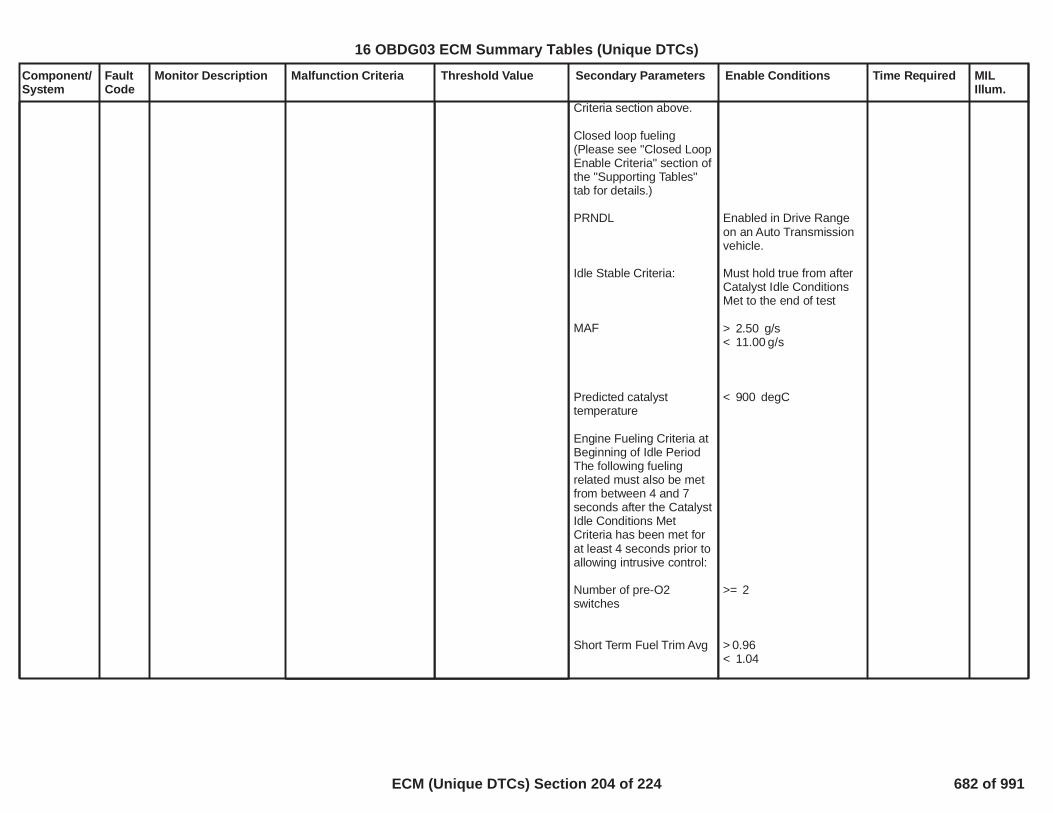
Component/System
FaultCode
Monitor Description Malfunction Criteria Threshold Value Secondary Parameters Enable Conditions Time Required MILIllum.
Criteria section above.
Closed loop fueling(Please see "Closed LoopEnable Criteria" section ofthe "Supporting Tables"tab for details.)
PRNDL
Idle Stable Criteria:
MAF
Predicted catalysttemperature
Engine Fueling Criteria atBeginning of Idle PeriodThe following fuelingrelated must also be metfrom between 4 and 7seconds after the CatalystIdle Conditions MetCriteria has been met forat least 4 seconds prior toallowing intrusive control:
Number of pre-O2switches
Short Term Fuel Trim Avg
Enabled in Drive Rangeon an Auto Transmissionvehicle.
Must hold true from afterCatalyst Idle ConditionsMet to the end of test
> g/s2.50< g/s11.00
< degC900
>= 2
> 0.96< 1.04
16 OBDG03 ECM Summary Tables (Unique DTCs)
ECM (Unique DTCs) Section 204 of 224 682 of 991
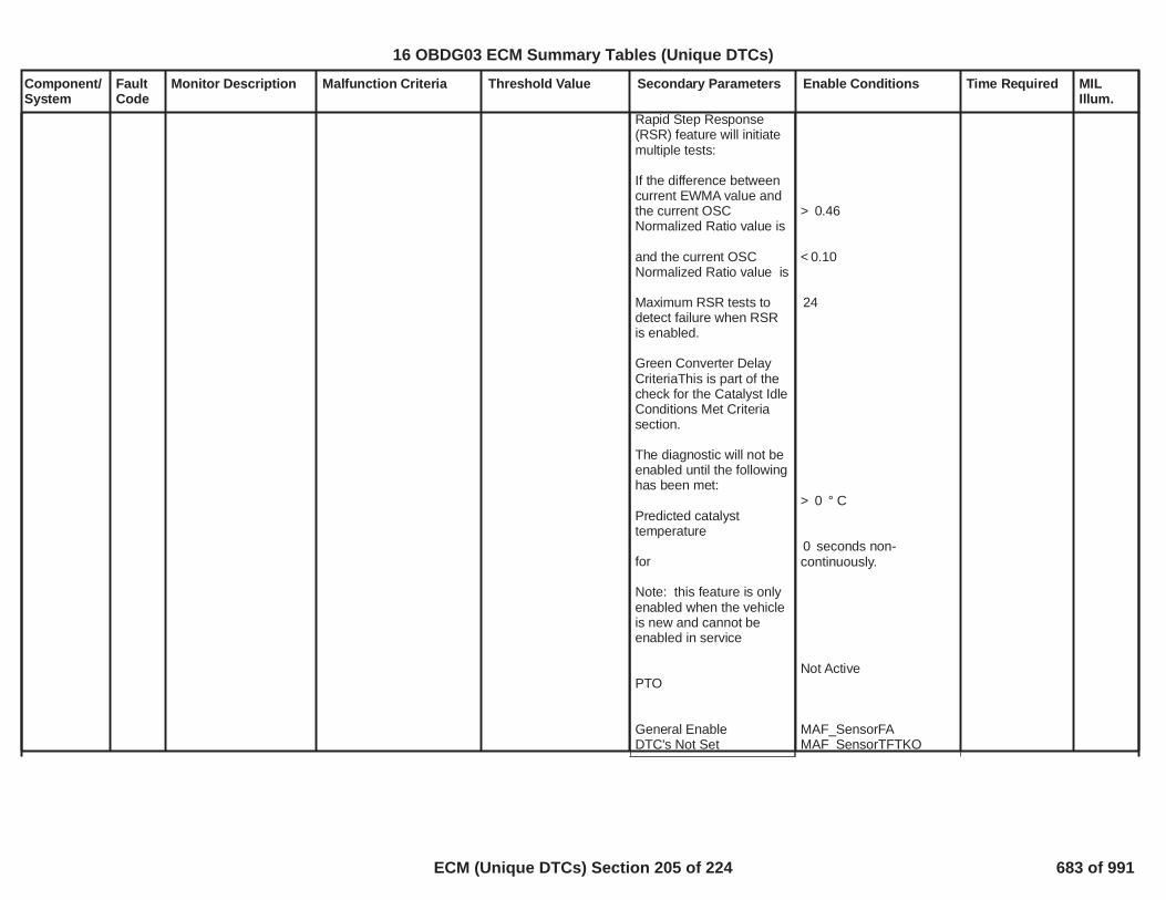
Component/System
FaultCode
Monitor Description Malfunction Criteria Threshold Value Secondary Parameters Enable Conditions Time Required MILIllum.
Rapid Step Response(RSR) feature will initiatemultiple tests:
If the difference betweencurrent EWMA value andthe current OSCNormalized Ratio value is
and the current OSCNormalized Ratio value is
Maximum RSR tests todetect failure when RSRis enabled.
Green Converter DelayCriteriaThis is part of thecheck for the Catalyst IdleConditions Met Criteriasection.
The diagnostic will not beenabled until the followinghas been met:
Predicted catalysttemperature
for
Note: this feature is onlyenabled when the vehicleis new and cannot beenabled in service
PTO
General EnableDTC's Not Set
> 0.46
< 0.10
24
> ° C0
seconds non-0continuously.
Not Active
MAF_SensorFAMAF_SensorTFTKO
16 OBDG03 ECM Summary Tables (Unique DTCs)
ECM (Unique DTCs) Section 205 of 224 683 of 991

Component/System
FaultCode
Monitor Description Malfunction Criteria Threshold Value Secondary Parameters Enable Conditions Time Required MILIllum.
AmbPresDfltdStatusIAT_SensorCircuitFAIAT_SensorCircuitTFTKOECT_Sensor_FAO2S_Bank_1_Sensor_1_FAO2S_Bank_1_Sensor_2_FAO2S_Bank_2_Sensor_1_FAO2S_Bank_2_Sensor_2_FAFuelTrimSystemB1_FAFuelTrimSystemB1_TFTKOFuelTrimSystemB2_FAFuelTrimSystemB2_TFTKOEngineMisfireDetected_FAEvapPurgeSolenoidCircuit_FAIAC_SystemRPM_FAEGRValvePerformance_FAEGRValveCircuit_FACamSensorAnyLocationFACrankSensor_FATPS_Performance_FAEnginePowerLimited
16 OBDG03 ECM Summary Tables (Unique DTCs)
ECM (Unique DTCs) Section 206 of 224 684 of 991

Component/System
FaultCode
Monitor Description Malfunction Criteria Threshold Value Secondary Parameters Enable Conditions Time Required MILIllum.
FuelConductivityOut OfRange(water infuel)
P2269 Detects the presenceof High ConductivityFuel (e.g. water in fuel)via a specific range ofsensor frequency.High conductivity in thefuel causes asignificant upward shiftin the sensor's outputfrequency.
Flex Fuel Sensor OutputFrequency
> Hertz185 Powertrain Relay > Volts11.0 failures out50of samples63100 ms loopContinuous
Type B,2 Trips
16 OBDG03 ECM Summary Tables (Unique DTCs)
ECM (Unique DTCs) Section 207 of 224 685 of 991

Component/System
FaultCode
Monitor Description Malfunction Criteria Threshold Value Secondary Parameters Enable Conditions Time Required MILIllum.
O2SensorCircuitRange /PerformanceBank 1Sensor 1
P2A00 This DTC determines ifthe O2 sensor voltageis not meeting thevoltage criteria toenable closed loopfueling.
===================Closed Loop O2S readyflag
A) O2S signal must beTo set Closed Loop readyflag
===================Closed Loop O2S readyflag
B) Once set to ready O2Scannot be
forThen set Closed Loopready flag
===================
===============
= False
< mvolts1,250
= True
===============
= True
> mvolts1,250
> seconds5.0= False
================
No Active DTC's
System VoltageEngine SpeedEngine AirflowEngine CoolantEngine Metal OvertempActiveConverter OvertempActiveFuel StateAFM StatusPredicted Exhaust Temp(B1S1)Engine run timeFuel Enrichment
All of the above met for
TPS_ThrottleAuthorityDefaultedMAP_SensorFAECT_Sensor_FAFuelInjectorCircuit_FAP0131, P0151P0132, P0152
< Volts <10.0 32.0 RPM 500 3,400 gps 3.2 30.0
ºC68.0
= False= FalseDFCO not active= All Cylinders active
ºC0.0> seconds100= Not Active
> seconds5
failures out200of samples.250
Frequency:Continuous 100msec loop
Type B,2 Trips
16 OBDG03 ECM Summary Tables (Unique DTCs)
ECM (Unique DTCs) Section 208 of 224 686 of 991

Component/System
FaultCode
Monitor Description Malfunction Criteria Threshold Value Secondary Parameters Enable Conditions Time Required MILIllum.
RadiatorCoolantTemp -EngineCoolantTemp (ECT)Correlation(DCRD)
P00B6 This DTC detects adifference betweenECT and RCT after asoak condition.
A failure will be reported ifany of the following occur:
1) Absolute differencebetween ECT at power up& RCT at power up is anIAT based threshold tablelookup value(fast fail).
2) Absolute differencebetween ECT at power up& RCT at power up is > by
ºC and a block20.0heater has not beendetected.
3) ECT at power up >RCT at power up by 20.0ºC and the time spentcranking the enginewithout starting is greaterthan or equal to 10.0seconds with theLowFuelConditionDiag
See the table named:P00B6_Fail if powerup ECT exceeds RCTby these valuesin the Supportingtables section
= False
No Active DTC's
Engine Off Soak TimePropulsion Off Soak TimeNon-volatile memoryinitization
Test complete this tripTest aborted this tripIATLowFuelCondition Diag
==================Block Heater detection isenabled when either ofthe following occurs:
1) ECT at power up > IATat power up by2) Cranking time
==================Block Heater is detectedand diagnostic is abortedwhen 1) or 2) occurs.
1a) Vehicle drive time
1b) Vehicle speed
1c) Additional Vehicledrive time is provided to1a when Vehicle speed is
VehicleSpeedSensor_FAIAT_SensorCircuitFATHMR_RCT_Sensor_Ckt_FATHMR_ECT_Sensor_Ckt_FAIgnitionOffTimeValidTimeSinceEngineRunningValid> seconds28,800> seconds0
= Not occurred
= False= False ºC-7
= False
==================
> ºC20.0< Seconds10.0
==================
> Seconds with60
> MPH and14.9
times the seconds0.00with vehicle speed below
1 failure500 msec/sampleOnce per validcold start
Type B,2 Trips
1
16 OBDG03 ECM Summary Tables (Unique DTCs)
ECM (Unique DTCs) Section 209 of 224 687 of 991
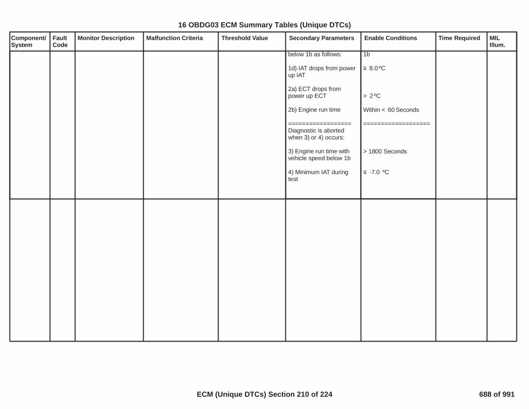
Component/System
FaultCode
Monitor Description Malfunction Criteria Threshold Value Secondary Parameters Enable Conditions Time Required MILIllum.
below 1b as follows:
1d) IAT drops from powerup IAT
2a) ECT drops frompower up ECT
2b) Engine run time
==================Diagnostic is abortedwhen 3) or 4) occurs:
3) Engine run time withvehicle speed below 1b
4) Minimum IAT duringtest
1b
ºC8.0
> ºC2
Within < Seconds60
===================
> 1800 Seconds
ºC-7.0
2
16 OBDG03 ECM Summary Tables (Unique DTCs)
ECM (Unique DTCs) Section 210 of 224 688 of 991

Component/System
FaultCode
Monitor Description Malfunction Criteria Threshold Value Secondary Parameters Enable Conditions Time Required MILIllum.
Turbocharger BoostPressureSensorCircuit Low
P0237 Detects a continuousshort to low or open ineither the signal circuitor the turbochargerboost pressure sensor.
Turbocharger BoostPressure Voltage < % of 5 Volt17.0
Range(This is equal to 0.85Volts, or kPa)49.6
failures out320of samples400
1 sample every12.5 msec
Type B,2 Trips
3
16 OBDG03 ECM Summary Tables (Unique DTCs)
ECM (Unique DTCs) Section 211 of 224 689 of 991
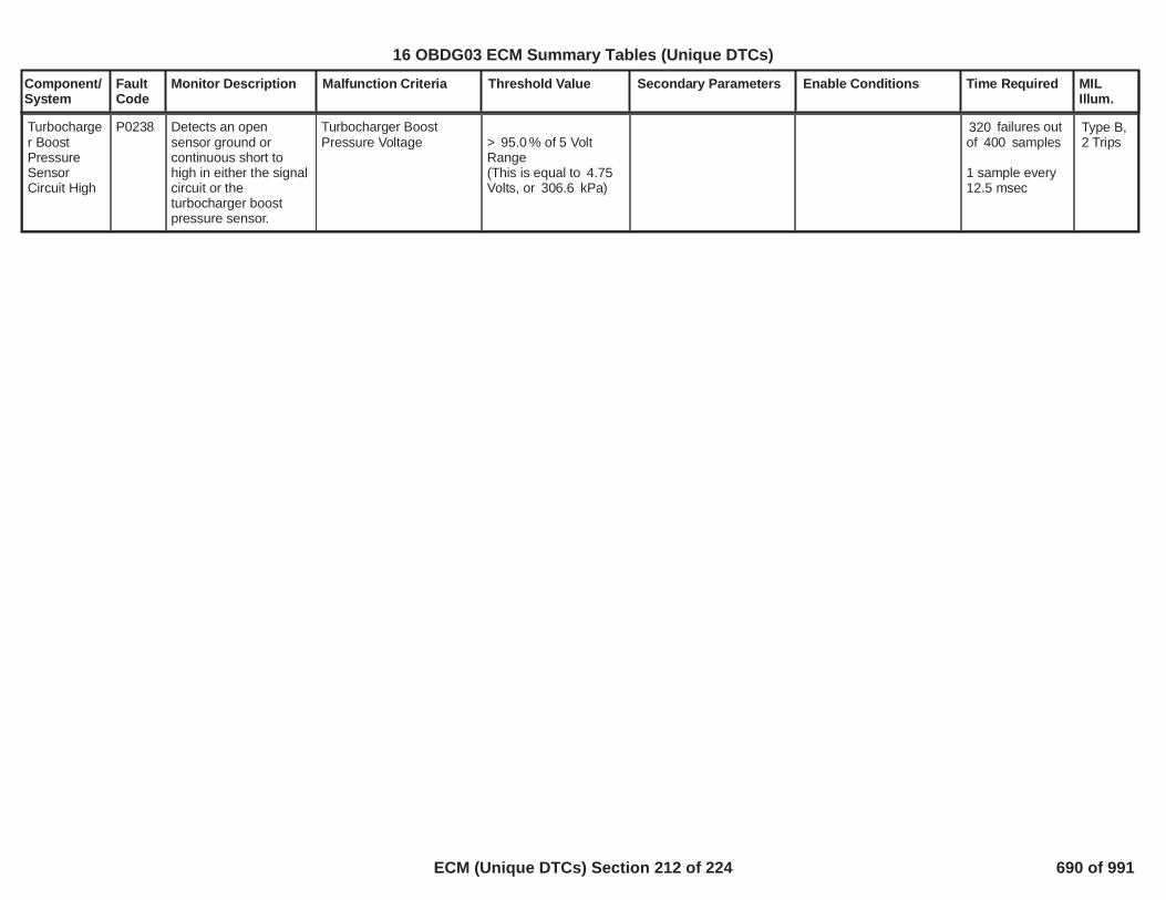
Component/System
FaultCode
Monitor Description Malfunction Criteria Threshold Value Secondary Parameters Enable Conditions Time Required MILIllum.
Turbocharger BoostPressureSensorCircuit High
P0238 Detects an opensensor ground orcontinuous short tohigh in either the signalcircuit or theturbocharger boostpressure sensor.
Turbocharger BoostPressure Voltage > % of 5 Volt95.0
Range(This is equal to 4.75Volts, or kPa)306.6
failures out320of samples400
1 sample every12.5 msec
Type B,2 Trips
4
16 OBDG03 ECM Summary Tables (Unique DTCs)
ECM (Unique DTCs) Section 212 of 224 690 of 991

Component/System
FaultCode
Monitor Description Malfunction Criteria Threshold Value Secondary Parameters Enable Conditions Time Required MILIllum.
BarometricPressure(BARO)SensorCircuit Low(boostedapplications)
P2228 Detects a continuousshort to low or open ineither the signal circuitor the BARO sensor.
BARO Voltage < % of 5 Volt40.0Range( Volts = kPa)2.0 50.9
failures out320of samples400
1 sample every12.5 msec
Type B,2 Trips
5
16 OBDG03 ECM Summary Tables (Unique DTCs)
ECM (Unique DTCs) Section 213 of 224 691 of 991

Component/System
FaultCode
Monitor Description Malfunction Criteria Threshold Value Secondary Parameters Enable Conditions Time Required MILIllum.
BarometricPressure(BARO)SensorCircuit High(boostedapplications)
P2229 Detects an opensensor ground orcontinuous short tohigh in either the signalcircuit or the BAROsensor.
BARO Voltage > % of 5 Volt90.0Range( Volts =4.5 115.0kPa)
failures out320of samples400
1 sample every12.5 msec
Type B,2 Trips
6
16 OBDG03 ECM Summary Tables (Unique DTCs)
ECM (Unique DTCs) Section 214 of 224 692 of 991

Component/System
FaultCode
Monitor Description Malfunction Criteria Threshold Value Secondary Parameters Enable Conditions Time Required MILIllum.
Intake AirPressureMeasurement System -MultipleSensorCorrelation(naturallyaspiratedwith TIAP/Baro sensor)
P00C7 Detects aninconsistency betweenpressure sensors in theinduction system inwhich a particularsensor cannot beidentified as the failedsensor
ABS(Manifold Pressure -Baro Pressure) > kPa10.0
Time between currentignition cycle and the lasttime the engine wasrunning
Engine is not rotating
Manifold PressureManifold PressureBaro PressureBaro Pressure
No Active DTCs:
No Pending DTCs:
> seconds10.0
>= kPa50.0<= kPa115.0>= kPa50.0<= kPa115.0
EngineModeNotRunTimerErrorMAP_SensorFAAAP_SnsrFA
MAP_SensorCircuitFPAAP_SnsrCktFP
failures out of4samples5
1 sample every12.5 msec
Type B,2 Trips
1
16 OBDG03 ECM Summary Tables (Unique DTCs)
ECM (Unique DTCs) Section 215 of 224 693 of 991

Component/System
FaultCode
Monitor Description Malfunction Criteria Threshold Value Secondary Parameters Enable Conditions Time Required MILIllum.
HybridPowertrainControlModule(HPC)RequestedMILIllumination
P0AC4 Monitors the HPC MILrequest line todetermine when theHPC has detected aMIL illuminating fault.
HPC Emissions-RelatedDTC set
Time since power-up 3seconds
Continuous Type A,No MIL
1
16 OBDG03 ECM Summary Tables (Unique DTCs)
ECM (Unique DTCs) Section 216 of 224 694 of 991

Component/System
FaultCode
Monitor Description Malfunction Criteria Threshold Value Secondary Parameters Enable Conditions Time Required MILIllum.
HybridControlTorqueRequestCircuit
P15F2 Determines if torquerequest from the HCPis valid
1. Serial Communication2’s complement not equalfor message $181 forStrong Hybrid or MildHybrid Applications
OR
2. Serial Communicationrolling count value shallbe + 1 from previous$181 message for StrongHybrid or Mild HybridApplications
Message <> 2'scomplement of EngineTorque Signal
and if Mild Hybrid:
Message <> 2'scomplement of MotorTorque Signal
OR
Message rolling countvalue <> previousmessage rolling countvalue plus one
Secondary High SpeedBus is Present and NoSerial communication lossto HCP (U1817)
Run Crank Active
Ingintion Voltage
No Serial communicationloss to HCP (U1817)
Hybrid Type = Mildor Strong
If Mild Hybrid Only:Torque source type =Crankshaft Torque
No loss ofcommunication
>= Sec0.50
> 6.41
= Mild
= Crankshaft Torque
1.>= Protect10errors out of 16samples
OR
2.>= 10Rolling count
errors out ofsamples16
Pass diagnosticif samples >=16
Performed everyreceivedmessage
Type A,1 Trips
2
16 OBDG03 ECM Summary Tables (Unique DTCs)
ECM (Unique DTCs) Section 217 of 224 695 of 991

Component/System
FaultCode
Monitor Description Malfunction Criteria Threshold Value Secondary Parameters Enable Conditions Time Required MILIllum.
Driver MotorTorqueDeliveredCircuit
P15F4 Determines if torquearchieved from BCP isvalid
1. Serial Communication2’s complement not equalfor message $0BF forMildHybrid Applications
OR
2. Serial Communicationrolling count value shallbe + 1 from previous$0BF message for MildHybridApplications
Message <> 2'scomplement of MotorTorque Signal
OR
Message rolling countvalue <> previousmessage rolling countvalue plus one
Secondary High SpeedBus is Present and NoSerial communication lossto BCP (U1817)
Run Crank Active
Low Voltage not Present
No loss ofCommunication
>= 0.50
> 6.41
1. >= Protect10errors out of 16samples
OR
2. >= 10Rolling counterrors out of 16samples
Executes in a12.5ms loop
Type A,1 Trip
3
16 OBDG03 ECM Summary Tables (Unique DTCs)
ECM (Unique DTCs) Section 218 of 224 696 of 991

Component/System
FaultCode
Monitor Description Malfunction Criteria Threshold Value Secondary Parameters Enable Conditions Time Required MILIllum.
HybridControlSpeedRequestCircuit
P15F9 Determines if torquerequest from the HCPis valid
1. Serial Communication2’s complement not equalfor message $281
OR
2. Serial Communicationrolling count value shallbe + 1 from previous$281 message
Message <> 2'scomplement ofmessage
Message rolling countvalue <> previousmessage rolling countvalue plus one
Secondary High SpeedBus is Present
No Serial communicationloss to HCP (U1817)
Run Crank Active >= Sec0.50
>= 10.00PasswordProtect errorsout of 16.00samples
OR
>= Rolling10.00count errors outof samples16.00
Pass diagnosticif samples >=16.00
Performed every12.5 msec
Type B,2 Trips
4
16 OBDG03 ECM Summary Tables (Unique DTCs)
ECM (Unique DTCs) Section 219 of 224 697 of 991

Component/System
FaultCode
Monitor Description Malfunction Criteria Threshold Value Secondary Parameters Enable Conditions Time Required MILIllum.
Brake PedalPositionSensorSignalMessageCounterIncorrect
P15FB Detects rolling count orprotection value errorsin Chassis Brake PedalPosition EmissionsRelated serial datasignal
If x of y rolling count /protection value faultsoccur, default brake pedalpositiion to zero forduration of fault
Chassis Brake PedalPosition EmissionsRelated Serial Data ErrorDiagnostic Enable
1.00 10.00/16.00counts
Type A,1 Trips
5
16 OBDG03 ECM Summary Tables (Unique DTCs)
ECM (Unique DTCs) Section 220 of 224 698 of 991

Component/System
FaultCode
Monitor Description Malfunction Criteria Threshold Value Secondary Parameters Enable Conditions Time Required MILIllum.
LostCommunication WithHybridPowertrainControlModule
U0293 This DTC monitors fora loss ofcommunication with theHybrid PowertrainControl Module.
Message is not receivedfrom controller for
Message $0B4
Message $0D3
Message $164
Message $186
Message $1DF
Message $3C1
seconds10.0
seconds10.0
seconds10.0
seconds0.5
seconds10.0
seconds10.0
General Enable Criteria:
U0073
Normal CAN transmissionon Bus A
Device Control
High Voltage VirtualNetwork Management
Ignition Voltage Criteria:
Run/Crank Ignitionvoltage
Power Mode
Off Cycle Enable Criteria:
KeCAND_b_OffKeyCycleDiagEnbl
Ignition Accessory LineandBattery Voltage
General Enable Criteriaand either Ignition VoltageCriteria or Off CycleEnable Criteria met for >
seconds3.0000
Power Mode is inaccessory or run or crankand High Voltage VirtualNetwork Management is
Not Active on Current KeyCycle
Enabled
Not Active
Not Active
> Volts6.41
= run
= 1(1 indicates enabled)
= Active
> Volts11.00
Diagnostic runsin 12.5 ms loop
Type A,1 Trips
6
16 OBDG03 ECM Summary Tables (Unique DTCs)
ECM (Unique DTCs) Section 221 of 224 699 of 991

Component/System
FaultCode
Monitor Description Malfunction Criteria Threshold Value Secondary Parameters Enable Conditions Time Required MILIllum.
not active for
U0293
Hybrid Powertrain ControlModule
> seconds0.4000
Not Active on Current KeyCycle
is present on the bus
7
16 OBDG03 ECM Summary Tables (Unique DTCs)
ECM (Unique DTCs) Section 222 of 224 700 of 991

Component/System
FaultCode
Monitor Description Malfunction Criteria Threshold Value Secondary Parameters Enable Conditions Time Required MILIllum.
LostCommunication WithHybridPowertrainControlModule onBus B
U1817 This DTC monitors fora loss ofcommunication with theHybrid PowertrainControl Module on BusB
Message is not receivedfrom controller for
Message $0A7
Message $0A9
Message $181
Message $1D3
Message $1D7
Message $1E3
Message $281
Message $291
seconds10.0
seconds10.0
seconds0.5
seconds10.0
seconds10.0
seconds10.0
seconds10.0
seconds10.0
General Enable Criteria:
U0074
Normal CAN transmissionon Bus B
Device Control
High Voltage VirtualNetwork Management
Ignition Voltage Criteria:
Run/Crank Ignitionvoltage
Power Mode
Off Cycle Enable Criteria:
KeCAND_b_OffKeyCycleDiagEnbl
Ignition Accessory LineandBattery Voltage
General Enable Criteriaand either Ignition VoltageCriteria or Off CycleEnable Criteria met for >3.0000seconds
Not Active on Current KeyCycle
Enabled
Not Active
Not Active
> Volts6.41
= run
= 1(1 indicates enabled)
= Active
> Volts11.00
Diagnostic runsin 12.5 ms loop
Type A,1 Trips
8
16 OBDG03 ECM Summary Tables (Unique DTCs)
ECM (Unique DTCs) Section 223 of 224 701 of 991

Component/System
FaultCode
Monitor Description Malfunction Criteria Threshold Value Secondary Parameters Enable Conditions Time Required MILIllum.
Power Mode is inaccessory or run or crankand High Voltage VirtualNetwork Management isnot active for
U1817
Hybrid Powertrain ControlModule
> seconds0.4000
Not Active on Current KeyCycle
is present on the bus
9
16 OBDG03 ECM Summary Tables (Unique DTCs)
ECM (Unique DTCs) Section 224 of 224 702 of 991

Engine run time greater thanClosed Loop Enable Clarification -KtFSTA_t_ClosedLoopAutostartKtFSTA_t_ClosedLoopAutostart
(HYBRID ONLY)
AutoStart CoolantX1 X2 X3 X4 X5 X6 X7 X8 X9 X10 X11Close Loop Enable TimeY1 Y2 Y3 Y4 Y5 Y6 Y7 Y8 Y9 Y10 Y11
andClosed Loop Enable Clarification -KtFSTA_t_ClosedLoopTimeKtFSTA_t_ClosedLoopTime
Start-Up CoolantX1 X2 X3 X4 X5 X6 X7 X8 X9 X10 X11Close Loop Enable TimeY1 Y2 Y3 Y4 Y5 Y6 Y7 Y8 Y9 Y10 Y11
and pre converter 02 sensor voltage lessthanClosed Loop Enable Clarification -KfFCLP_U_O2ReadyThrshLoKfFULC_U_O2_SensorReadyThrshLo(Switching Sensor)
Voltage< XXXXmilliVoltsforClosed Loop Enable Clarification -KcFULC_O2_SensorReadyEventsKcFULC_O2_SensorReadyEvents(Switching Sensor)
Time (events * 12.5 milliseconds)> XXXXeventsorClosed Loop Enable Clarification -KeWRSC_T_HtrCntrlCLKeWRSC_T_HtrCntrlCL(WRAF Sensor)andClosed Loop Enable Clarification -KeWRSI_T_PumpCurrentEnableKeWRSI_T_PumpCurrentEnable(WRAF Sensor)andCOSC (Converter Oxygen Storage Control) not
481
16 OBDG03 Closed Loop Enable Clarification: Calibration values are in the Supporting Tables
Closed Loop Enable Clarification 1 of 4 703 of 991

enabledandConsumed AirFuel Ratio is stoichiometry i.e. not in componentprotectionandPOPD or Catalyst Diagnostic not intrusiveandTurbo Scavenging Mode notenabledandAll cylinders whose valves are active also have their injectorsenabledandO2S_Bank_ 1_TFTKOO2S_Bank_ 2_TFTKOFuelInjectorCircuit_FACylDeacSystemTFTKOO2S_Bank_ 1_TFTKO, O2S_Bank_ 2_TFTKO, FuelInjectorCircuit_FA andCylnderDeacDriverTFTKO = False
Long Term FT Enable Criteria
Closed Loop Enable andCoolant greater thanClosed Loop Enable Clarification -KfFCLL_T_AdaptiveLoCoolantKfFCLL_T_AdaptiveLoCoolant
Coolant> XXXXCelciusor less thanClosed Loop Enable Clarification -KfFCLL_T_AdaptiveHiCoolantKfFCLL_T_AdaptiveHiCoolant
Coolant< XXXXCelciusandClosed Loop Enable Clarification -KtFCLL_p_AdaptiveLowMAP_LimitKtFCLL_p_AdaptiveLowMAP_Limit
Barometric PressureX1 X2 X3 X4 X5 X6 X7 X8 X9Manifold Air PressureY1 Y2 Y3 Y4 Y5 Y6 Y7 Y8 Y9
482
16 OBDG03 Closed Loop Enable Clarification: Calibration values are in the Supporting Tables
Closed Loop Enable Clarification 2 of 4 704 of 991

andTPS_ThrottleAuthorityDefaultedTPS_ThrottleAuthorityDefaulted =FalseandFlex Fuel Estimate Algorithm is not activeandExcessive fuel vapors boiling off from the engine oil algorithm (BOFR) is notenabledandCatalyst or EVAP large leak test notintrusive
Secondary Fuel Trim EnableCriteria
Closed Loop Enable andClosed Loop Enable Clarification -KfFCLP_U_O2ReadyThrshLoKfFCLP_U_O2ReadyThrshLo
Voltage< XXXXmilliVoltsforClosed Loop Enable Clarification -KcFCLP_Cnt_O2RdyCyclesThrshKcFCLP_Cnt_O2RdyCyclesThrsh
Time (events * 12.5 milliseconds)> XXXXevents
Long Term Secondary Fuel TrimEnable Criteria
Closed Loop Enable Clarification -KtFCLP_t_PostIntglDisableTimeKtFCLP_t_PostIntglDisableTime
Start-Up CoolantX1 X2 X3 X4 X5 X6 X7 X8 X9 X10 X11Post Integral Enable TimeY1 Y2 Y3 Y4 Y5 Y6 Y7 Y8 Y9 Y10 Y11
PlusClosed Loop Enable Clarification -KtFCLP_t_PostIntglRampInTimeKtFCLP_t_PostIntglRampInTime
483
16 OBDG03 Closed Loop Enable Clarification: Calibration values are in the Supporting Tables
Closed Loop Enable Clarification 3 of 4 705 of 991
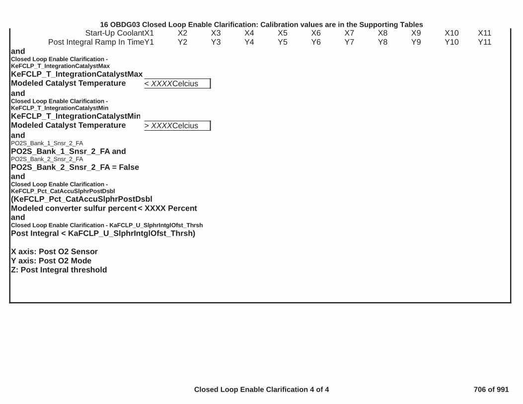
Start-Up CoolantX1 X2 X3 X4 X5 X6 X7 X8 X9 X10 X11Post Integral Ramp In TimeY1 Y2 Y3 Y4 Y5 Y6 Y7 Y8 Y9 Y10 Y11
andClosed Loop Enable Clarification -KeFCLP_T_IntegrationCatalystMaxKeFCLP_T_IntegrationCatalystMaxModeled Catalyst Temperature < XXXXCelciusandClosed Loop Enable Clarification -KeFCLP_T_IntegrationCatalystMinKeFCLP_T_IntegrationCatalystMinModeled Catalyst Temperature > XXXXCelciusandPO2S_Bank_1_Snsr_2_FAPO2S_Bank_1_Snsr_2_FA andPO2S_Bank_2_Snsr_2_FAPO2S_Bank_2_Snsr_2_FA = FalseandClosed Loop Enable Clarification -KeFCLP_Pct_CatAccuSlphrPostDsbl(KeFCLP_Pct_CatAccuSlphrPostDsblModeled converter sulfur percent< XXXX PercentandClosed Loop Enable Clarification - KaFCLP_U_SlphrIntglOfst_ThrshPost Integral < KaFCLP_U_SlphrIntglOfst_Thrsh)
X axis: Post O2 SensorY axis: Post O2 ModeZ: Post Integral threshold
484
16 OBDG03 Closed Loop Enable Clarification: Calibration values are in the Supporting Tables
Closed Loop Enable Clarification 4 of 4 706 of 991

OBD Coolant enableStarting in 11.15A software GM has created a coordinated signal within the ECM that serves as a master enable for diagnostics/controls thatuse coolant as an enable condition. Controls and diagnostics may choose to enable prior to this calculated signal, but calibrating beyond theOBD limit will not function because of this signal. This enable condition is also put on the CAN bus for other modules to consume as well.
KeTHMG_b_elecstatequipd = for this application0
For mechanical thermostat applications (KeTHMG_b_elecstatequipd = 0)OBD Coolant Enable Temp = P0128 Primary target temp – Calibratable offset (0-32) – 1OBD Coolant Enable Temp = - – 169.5 0.0
OBD Coolant Enable Temp = 68.5
For E-stat applications (KeTHMG_b_elecstatequipd = 1)
OBD Coolant Enable Temp = Max(Min(ECT Control Temp) – Primary Warm up delta, Min primary P0128 target) – Calibratable offset (0-32)– 1OBD Coolant Enable Temp = Max(Min(KaTHMC_T_TMS_EngCoolReq) - KaECTR_T_CTR_WrmUpDeltaTemp[0],KaECTR_T_CTR_WrmUpTargetMin[0]) - KeECTR_T_CTR_GlblMinOffst – 1OBD Coolant Enable Temp = Max( - , ) - – 190.5 19.0 69.5 0.0
OBD Coolant Enable Temp = 70.5
485
16 OBDG03 OBD Coolant Enable Criteria (OBD Coolant Enable Criteria)
OBD Coolant Enable Criteria 1 of 1 707 of 991

********************************************************************************************************************************************************************************************************************************************************************
Exhaust Cam Phsr Enable
Exhaust Cam Phsr Enable = TRUE if:
DTCs not set:CrankSensor_TFTKOCamSnsrExhTFTKOCamLctnExhFA
AND
diagnostic has executed and passedCamLctnExhFA
AND
Cam edge locations have been learned
AND
[ Intake Cam Phsr Enable = TRUEORIntake Park Position is Retarded ( ) ]TRUE
AND
[ = TRUECatalyst Warmup EnabledANDEngine RPM > 900.00ANDEngine Run Time > sec ]P0011_P0021_P05CC_P05CD_P0014_P0024_P05CE_P05CF_ColdStartEngRunning
OR
[ Engine is running and engine power is requested
16 OBDG03 Dilution Definitions
Dilution Definitions 1 of 8 708 of 991
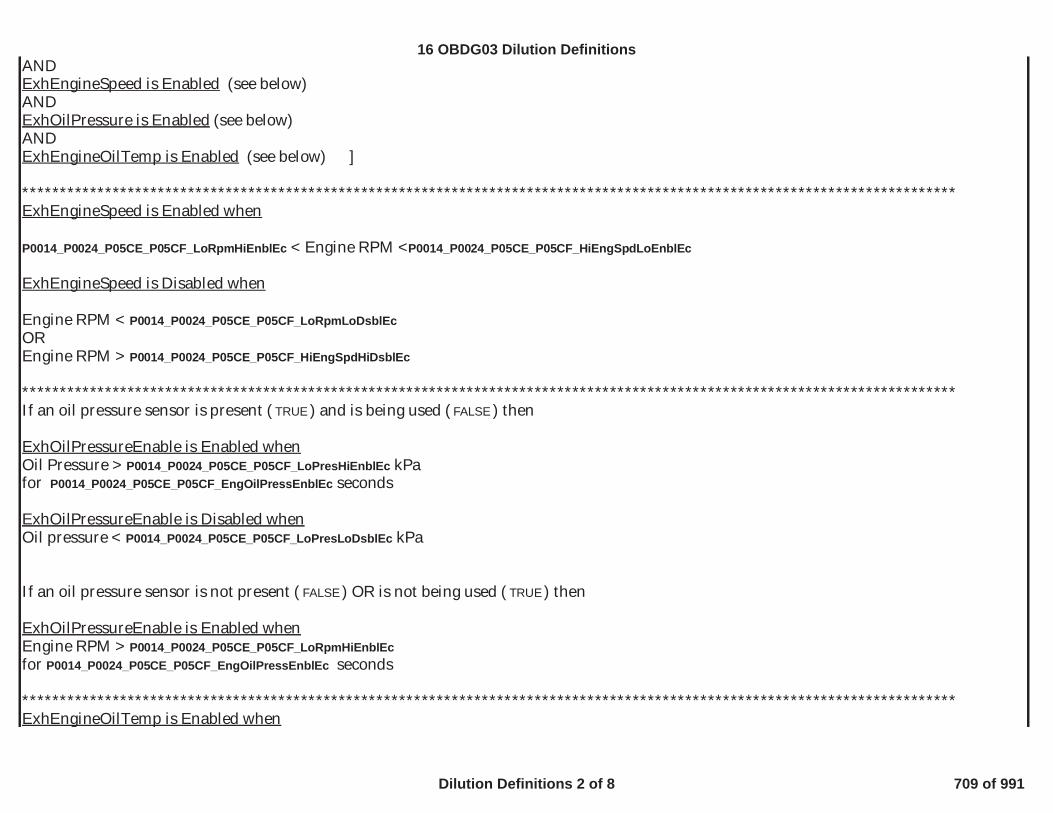
ANDExhEngineSpeed is Enabled (see below)ANDExhOilPressure is Enabled (see below)ANDExhEngineOilTemp is Enabled (see below) ]
****************************************************************************************************************************ExhEngineSpeed is Enabled when
< Engine RPM <P0014_P0024_P05CE_P05CF_LoRpmHiEnblEc P0014_P0024_P05CE_P05CF_HiEngSpdLoEnblEc
ExhEngineSpeed is Disabled when
Engine RPM < P0014_P0024_P05CE_P05CF_LoRpmLoDsblEcOREngine RPM > P0014_P0024_P05CE_P05CF_HiEngSpdHiDsblEc
****************************************************************************************************************************If an oil pressure sensor is present ( ) and is being used ( ) thenTRUE FALSE
ExhOilPressureEnable is Enabled whenOil Pressure > kPaP0014_P0024_P05CE_P05CF_LoPresHiEnblEcfor secondsP0014_P0024_P05CE_P05CF_EngOilPressEnblEc
ExhOilPressureEnable is Disabled whenOil pressure < kPaP0014_P0024_P05CE_P05CF_LoPresLoDsblEc
If an oil pressure sensor is not present ( ) OR is not being used ( ) thenFALSE TRUE
ExhOilPressureEnable is Enabled whenEngine RPM > P0014_P0024_P05CE_P05CF_LoRpmHiEnblEcfor secondsP0014_P0024_P05CE_P05CF_EngOilPressEnblEc
****************************************************************************************************************************ExhEngineOilTemp is Enabled when
16 OBDG03 Dilution Definitions
Dilution Definitions 2 of 8 709 of 991

< Engine Oil Temp < deg C-35.00 135.00
ExhEngineOilTemp is Disabled whenEngine Oil Temp < deg C-38.00OREngine Oil Temp > deg C140.00
************************************************************************************************************************************************************************************************************************************************************
Intake Cam Phsr Enable
Intake Cam Phsr Enable = TRUE if:
DTCs not set:CrankSensor_TFTKOCamSnsrIntTFTKOCamLctnIntFA
AND
has executed and passedCamLctnIntFA
AND
Cam edge locations have been learned
AND
[ = TRUECatalyst Warmup EnabledANDEngine RPM > 900.00ANDEngine Run Time > sec]P0011_P0021_P05CC_P05CD_P0014_P0024_P05CE_P05CF_ColdStartEngRunning
OR
16 OBDG03 Dilution Definitions
Dilution Definitions 3 of 8 710 of 991

[ Engine is running and engine power is requestedANDIntEngineSpeed is EnabledANDIntOilPressure is EnabledANDIntEngineOilTemp is Enabled ]
********************************************************************************************************IntEngineSpeed is Enabled when
< Engine RPM <P0011_P0021_P05CC_P05CD_LoRpmHiEnblIc P0011_P0021_P05CC_P05CD_HiEngSpdLoEnblIc
IntEngineSpeed is Disabled when
Engine RPM < P0011_P0021_P05CC_P05CD_LoRpmLoDsblIcOREngine RPM > P0011_P0021_P05CC_P05CD_HiEngSpdHiDsblIc
********************************************************************************************************If an oil pressure sensor is present ( ) and is being used ( ) thenTRUE FALSE
IntOilPressureEnable is Enabled whenOil Pressure > kPaP0011_P0021_P05CC_P05CD_LoPresHiEnblIcfor secondsP0011_P0021_P05CC_P05CD_EngOilPressEnblIc
IntOilPressureEnable is Disabled whenOil pressure < P0011_P0021_P05CC_P05CD_LoPresLoDsblIc
If an oil pressure sensor is not present ( ) or is not being used ( ) thenFALSE TRUE
IntOilPressureEnable is Enabled whenEngine RPM > P0011_P0021_P05CC_P05CD_LoRpmHiEnblIcfor secondsP0011_P0021_P05CC_P05CD_EngOilPressEnblIc
********************************************************************************************************IntEngineOilTemp is Enabled when
16 OBDG03 Dilution Definitions
Dilution Definitions 4 of 8 711 of 991

< Engine Oil Temp < deg C-35.00 135.00
IntEngineOilTemp is Disabled whenEngine Oil Temp < deg C-38.00OREngine Oil Temp > deg C140.00
****************************************************************************************************************************************************************************************************************************************************************ReducedEngineCapacityMode_Enable
REDUCED CAPACITY CONTROL ENABLE CONDITIONS:Conditions below must be met for >= seconds before cylinder deactivation will begin in regular mode0.3
Neutral Idle Mode (NI) operational checks:Allowed in NI ( )FALSETime NI mode shall be active >= seconds1.0Vehicle Speed for NI
< mph to Enter0.0> mph to Exit0.0
PRNDL position in NI = False (For details see Supporting Tables)VCE_PRNDL_NI_DisablesEngine RPM lower limit for NI > rpm475Transmission gear for NI = FALSE (For details see Supporting Tables)VCE_TransGear_DisablesNITorque based AFM entry conditions: NI Mode ActiveIndicated Torque < minus NmVCE_NormalMode_MaxTorque_Gr5 10.0 (Function of Gear: VCE_NormalMode_MaxTorque_Gr1 - Gr8,for details see Supporting Tables)
Normal Mode operational checks:Engine running (based on engine off time)
Maximum of or > seconds (For details see Supporting Tables)30.0 VCE_StartUpDelayTimeEngine RPM
> + RPM ANDVCE_EngineRPM_LowerLmt 50< - RPM (For details see Supporting Tables)VCE_EngineRPM_UpperLmt 200
Vehicle Speed (in Gear) >= mph11.2Vehicle Speed (P/N) <= mph5.0Vehicle Speed based on PRNDL < VCE_VehicleSpeed_PRNDL_Enable
16 OBDG03 Dilution Definitions
Dilution Definitions 5 of 8 712 of 991

Engine RPM PRNDL Feature is (When TRUE, will enable AFM only if transmission is not in a defaulted state)TRUEEngine coolant (deac) >= and <= deg C40 241Ignition voltage >= volts11.0Engine Oil Temperature >= and <= deg C20 128Engine Oil Pressure >= and <= KPa200 780Oil pump intrusive test = FALSE (refer to P06DD and P06DE)Oil aeration present: Aeration enabled by engine RPM > for second(s), disabled by engine RPM < for second(s)3,100 10 3,000 50
= FALSECatalyst Warmup EnabledPOPD: Not activeDeceleration Fuel Cut Off: Not activeFuel shut off (FSO) delay: Not active >= second(s)3Green Engine mode: Not activePedal Position < pct48Brake booster vacuum >= KPa0Transmission gear = FALSE (For details see Supporting Tables)VCE_TransGear_DisablesGear Shift: not currently in progress4WD State: not = 4 low rangeTime since last AFM mode event >= second(s)3After exiting AFM mode for max time, must be in all cylinder mode for >= second(s)60Tip in Bump: Not activeAFM is disabled at high percent ethanol: Ethanol concentration > % disables AFM. Once disabled, ethanol concentration must be < % to95 90re-enableIf feature is enabled, AFM is allowed only when percent ethanol learn is not in progress: Feature is FALSEAFIM diagnostic status: Not activeA/C clutch transition: Not currently in progressETC power management mode: Not activeHeater performance: Not in heater perforamance mode
Torque based AFM entry conditions:ECO Mode Active: Indicated Torque < minusVCE_ECOMode_MaxTorque_Gr5 VCE_ECOMode_EnableTorqueHyst
(Function of Gear: VCE_ECOMode_MaxTorque_Gr1 - Gr8, For details see Supporting Tables)
Normal Mode: Indicated Torque < minusVCE_NormalMode_MaxTorque_Gr5 VCE_NormalMode_EnableTorqueHyst (Function of Gear: VCE_NormalMode_MaxTorque_Gr1 - Gr8, For details see Supporting Tables)
IF DEACTIVATED, ANY OF THE CONDITIONS BELOW WILL FORCE CYLINDER REACTIVATION:If deactivation mode is active for >= seconds480
16 OBDG03 Dilution Definitions
Dilution Definitions 6 of 8 713 of 991

then reactivation will occur if: >= seconds600Deac mode active orDelta vacuum > or < kPa5 -5Vehicle Speed for NI exit < Kph0ETC Power management mode: ActiveConverter overtemp protect: ActiveHot coolant mode: ActiveEngine running = FalseEngine overspeed protection: ActiveEngine metal overtemp protect: ActiveCat. temp low: ActiveFour Wheel Drive: In low rangeEngine misfire: DetectedHeater performance: ActivePOPD Intrusive tests: Active (see P2270-P2273, P013A-P014B)
Torque based AFM exit conditions:ECO Mode Active: Indicated Torque < VCE_ECOMode_MaxTorque_Gr5
(Function of Gear: VCE_ECOMode_MaxTorque_Gr1 - Gr8, For details see Supporting Tables)
Normal Mode: Indicated Torque < VCE_NormalMode_MaxTorque_Gr5 (Function of Gear: VCE_NormalMode_MaxTorque_Gr1 - Gr8, For details see Supporting Tables)
Engine Vacuum: (For details see Supporting Tables)VCE_MinVacReducedTorqModeIgnition voltage < volts11Engine coolant < or > Deg C36 245Vehicle speed < mph6.2Brake booster vacuum < kPa0Engine oil temperature < or > Deg C18 130Pedal Position > %50Piston Protection: Active
No active DTC's for control enable:Fault Bundles:Catalyst Warmup EnabledEngOilPressureSensorFAEnginePowerLimitedCrankSensor_TFTKO
16 OBDG03 Dilution Definitions
Dilution Definitions 7 of 8 714 of 991

EngineTorqueEstInaccurateVehicleSpeedSensorErrorECT_Sensor_FABrakeBoosterVacuumValidIAT_SensorFACylDeacDriverFaultCylDeacAllDriverFaultMAP_EngineVacuumStatusPowertrainRelayFaultCamSensorAnyLctnTFTKOOilPmpStuckHighVCER_TorqueSecurityFourWheelDriveLowStateInvalid
16 OBDG03 Dilution Definitions
Dilution Definitions 8 of 8 715 of 991
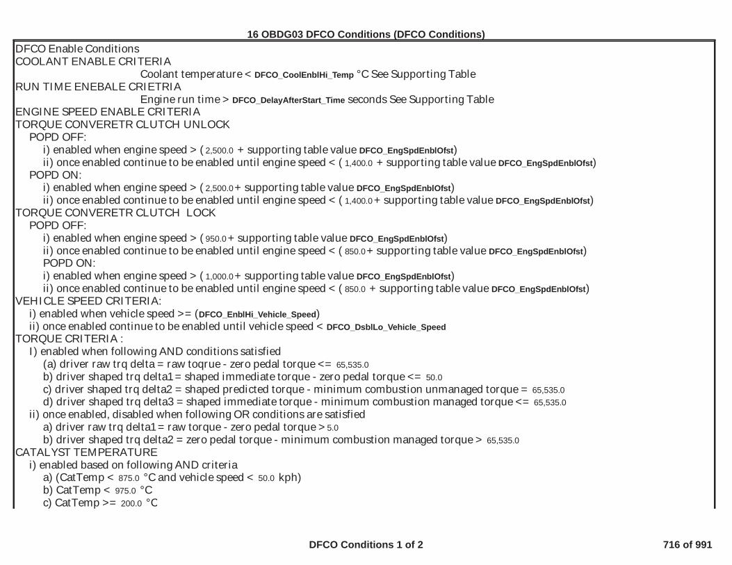
DFCO Enable ConditionsCOOLANT ENABLE CRITERIA
Coolant temperature < °C See Supporting TableDFCO_CoolEnblHi_TempRUN TIME ENEBALE CRIETRIA
Engine run time > seconds See Supporting TableDFCO_DelayAfterStart_TimeENGINE SPEED ENABLE CRITERIATORQUE CONVERETR CLUTCH UNLOCK
POPD OFF:i) enabled when engine speed > ( + supporting table value )2,500.0 DFCO_EngSpdEnblOfstii) once enabled continue to be enabled until engine speed < ( + supporting table value )1,400.0 DFCO_EngSpdEnblOfst
POPD ON:i) enabled when engine speed > ( + supporting table value )2,500.0 DFCO_EngSpdEnblOfstii) once enabled continue to be enabled until engine speed < ( + supporting table value )1,400.0 DFCO_EngSpdEnblOfst
TORQUE CONVERETR CLUTCH LOCKPOPD OFF:
i) enabled when engine speed > ( + supporting table value )950.0 DFCO_EngSpdEnblOfstii) once enabled continue to be enabled until engine speed < ( + supporting table value )850.0 DFCO_EngSpdEnblOfstPOPD ON:i) enabled when engine speed > ( + supporting table value )1,000.0 DFCO_EngSpdEnblOfstii) once enabled continue to be enabled until engine speed < ( + supporting table value )850.0 DFCO_EngSpdEnblOfst
VEHICLE SPEED CRITERIA:i) enabled when vehicle speed >= ( )DFCO_EnblHi_Vehicle_Speedii) once enabled continue to be enabled until vehicle speed < DFCO_DsblLo_Vehicle_Speed
TORQUE CRITERIA :I) enabled when following AND conditions satisfied
(a) driver raw trq delta = raw toqrue - zero pedal torque <= 65,535.0b) driver shaped trq delta1 = shaped immediate torque - zero pedal torque <= 50.0c) driver shaped trq delta2 = shaped predicted torque - minimum combustion unmanaged torque = 65,535.0d) driver shaped trq delta3 = shaped immediate torque - minimum combustion managed torque <= 65,535.0
ii) once enabled, disabled when following OR conditions are satisfieda) driver raw trq delta1 = raw torque - zero pedal torque > 5.0b) driver shaped trq delta2 = zero pedal torque - minimum combustion managed torque > 65,535.0
CATALYST TEMPERATUREi) enabled based on following AND criteria
a) (CatTemp < °C and vehicle speed < kph)875.0 50.0b) CatTemp < °C975.0c) CatTemp >= °C200.0
494
16 OBDG03 DFCO Conditions (DFCO Conditions)
DFCO Conditions 1 of 2 716 of 991

d) CatalystWarmupEnabled = FALSEii) once enabled, disabled when following OR conditions are met
OTHER CONDITIONS:a) Transmission is not about to unlockb) Engine not about to stallc) Transmission is not shifting if already not in DFCOd) POPD or EOSD
1) POPD requesting DFCO or neither requesting DFCO OFF nor inhibit DFCO2) EOSD not active
e) EVAP does not inhibit DFCOf) O2 response test is not inhibiting DFCO eventg) Throttle is not in default mode
495
16 OBDG03 DFCO Conditions (DFCO Conditions)
DFCO Conditions 2 of 2 717 of 991

Initial Supporting table - Multiple DTC Use - Block learn cells to enable Post oxygen sensor testsOBD GROUP:OBD GROUP: GGMX TESTTEST GROUP: G
Description: KaPOPD_PostCellEnbl - A table of adaptive (Block Learn) cells in which to enable the post oxygen sensor tests.
Notes: Note: When Table column headings match the calibration value below it, that individual cell is enabled.The cell numbers in the table are defined as:
CeFADR_e_Cell00_PurgOnAirMode5 = 0,CeFADR_e_Cell01_PurgOnAirMode4 = 1,CeFADR_e_Cell02_PurgOnAirMode3 = 2,CeFADR_e_Cell03_PurgOnAirMode2 = 3,CeFADR_e_Cell04_PurgOnAirMode1 = 4,CeFADR_e_Cell05_PurgOnAirMode0 = 5,CeFADR_e_Cell06_PurgOnIdle = 6,CeFADR_e_Cell07_PurgOnDecel = 7,CeFADR_e_Cell08_PurgOffAirMode5 = 8,CeFADR_e_Cell09_PurgOffAirMode4 = 9,CeFADR_e_Cell10_PurgOffAirMode3 = 10,CeFADR_e_Cell11_PurgOffAirMode2 = 11,CeFADR_e_Cell12_PurgOffAirMode1 = 12,CeFADR_e_Cell13_PurgOffAirMode0 = 13,CeFADR_e_Cell14_PurgOffIdle = 14,CeFADR_e_Cell15_PurgOffDecel = 15
y/x 0 1 2 3 4 5 6 7 8 9 10 11 12 13 14 151 7 7 7 7 7 7 7 7 15 15 15 15 15 15 15 15
496
16 OBDG03 Initial Supporting Tables
Initial Supporting Tables 1 of 191 718 of 991

Initial Supporting table - Multiple DTC Use_Green Sensor Delay Criteria - AirflowOBD GROUP:OBD GROUP: G TESTTEST GROUP: G IN4, FED---BIN4EMISSIONS STDS: Bin
Description: This Calibration is the airflow (in gps) above which the green airflow is acculmulated to expire the condition.
Notes: Used for: P0133, P013A, P013B, P013C, P013D, P013E, P013F, P014A, P014B, P0153, P015A, P015B, P015C, P015D, P1133, P1153, P2270, P2271, P2272 and P2273. Thespecific diagnostic (from summary table) will not be enabled until the next ignition cycle after the airflow criteria below (by sensor location) has been met:
y/x 1
1 22
497
16 OBDG03 Initial Supporting Tables
Initial Supporting Tables 2 of 191 719 of 991

Initial Supporting table - Multiple DTC Use_Green Sensor Delay Criteria - LimitOBD GROUP:OBD GROUP: GGMXO TESTTEST GROUP: G L---BIN4, FED---BIN4EMISSIONS STDS: Bin
Description: This Calibration is the acculmulated airflow (in grams) limit above which the green condition is expired
Notes: Used for: P0133, P013A, P013B, P013C, P013D, P013E, P013F, P014A, P014B, P0153, P015A, P015B, P015C, P015D, P1133, P1153, P2270, P2271, P2272 and P2273. Note:This feature is only enabled when the vehicle is new and cannot be enabled in service
y/x CiOXYR_O2_Bank1_Sensor1 CiOXYR_O2_Bank1_Sensor2 CiOXYR_O2_Bank2_Sensor1 CiOXYR_O2_Bank2_Sensor21 120,000 120,000 120,000 120,000
498
16 OBDG03 Initial Supporting Tables
Initial Supporting Tables 3 of 191 720 of 991

Initial Supporting table - P0011_CamPosErrorLimIc1OBD GROUP:OBD GROUP: TESTTEST GROUP: G AL---BIN4, FED---BIN4EMISSIONS STDS: Bin 4
Description: P0011 - Cam Position Error Limit for performance diagnostic
Notes: KtPHSD_phi_CamPosErrorLimIc1
y/x -40 -28 -16 -4 8 20 32 44 56 68 80 92 104 116 128 140 152
400 6.0 6.0 6.0 6.0 6.0 6.0 6.0 6.0 6.0 6.0 6.0 6.0 6.0 6.0 6.0 6.0 6.0
800 6.0 6.0 6.0 6.0 6.0 6.0 6.0 6.0 6.0 6.0 6.0 6.0 6.0 6.0 6.0 6.0 6.0
1,200 6.0 6.0 6.0 6.0 6.0 6.0 6.0 6.0 6.0 6.0 6.0 6.0 6.0 6.0 6.0 6.0 6.0
1,600 6.0 6.0 6.0 6.0 6.0 6.0 6.0 6.0 6.0 6.0 6.0 6.0 6.0 6.0 6.0 6.0 6.0
2,000 6.0 6.0 6.0 6.0 6.0 6.0 6.0 6.0 6.0 6.0 6.0 6.0 6.0 6.0 6.0 6.0 6.0
2,400 6.0 6.0 6.0 6.0 6.0 6.0 6.0 6.0 6.0 6.0 6.0 6.0 6.0 6.0 6.0 6.0 6.0
2,800 6.0 6.0 6.0 6.0 6.0 6.0 6.0 6.0 6.0 6.0 6.0 6.0 6.0 6.0 6.0 6.0 6.0
3,200 6.0 6.0 6.0 6.0 6.0 6.0 6.0 6.0 6.0 6.0 6.0 6.0 6.0 6.0 6.0 6.0 6.0
3,600 6.0 6.0 6.0 6.0 6.0 6.0 6.0 6.0 6.0 6.0 6.0 6.0 6.0 6.0 6.0 6.0 6.0
4,000 6.0 6.0 6.0 6.0 6.0 6.0 6.0 6.0 6.0 6.0 6.0 6.0 6.0 6.0 6.0 6.0 6.0
4,400 6.0 6.0 6.0 6.0 6.0 6.0 6.0 6.0 6.0 6.0 6.0 6.0 6.0 6.0 6.0 6.0 6.0
4,800 6.0 6.0 6.0 6.0 6.0 6.0 6.0 6.0 6.0 6.0 6.0 6.0 6.0 6.0 6.0 6.0 6.0
5,200 6.0 6.0 6.0 6.0 6.0 6.0 6.0 6.0 6.0 6.0 6.0 6.0 6.0 6.0 6.0 6.0 6.0
5,600 6.0 6.0 6.0 6.0 6.0 6.0 6.0 6.0 6.0 6.0 6.0 6.0 6.0 6.0 6.0 6.0 6.0
6,000 6.0 6.0 6.0 6.0 6.0 6.0 6.0 6.0 6.0 6.0 6.0 6.0 6.0 6.0 6.0 6.0 6.0
6,400 6.0 6.0 6.0 6.0 6.0 6.0 6.0 6.0 6.0 6.0 6.0 6.0 6.0 6.0 6.0 6.0 6.0
6,800 6.0 6.0 6.0 6.0 6.0 6.0 6.0 6.0 6.0 6.0 6.0 6.0 6.0 6.0 6.0 6.0 6.0
499
16 OBDG03 Initial Supporting Tables
Initial Supporting Tables 4 of 191 721 of 991

Initial Supporting table - P0011_P0021_P05CC_P05CD_EngOilPressEnblIcOBD GROUP:OBD GROUP: TESTTEST GROUP: G ED---BIN4EMISSIONS STDS: Bin 4
Description: Delay time before the oil pressure enable flag is set assuming all the oil pressure enable criteria are met
Notes: KtPHSC_t_EngOilPressEnblIc
y/x -40 -28 -16 -4 8 20 32 44 56 68 80 92 104 116 128 140 152
1 6 6 6 4 4 3 3 2 1 1 1 1 1 1 1 1 1
500
16 OBDG03 Initial Supporting Tables
Initial Supporting Tables 5 of 191 722 of 991

Initial Supporting table - P0011_P0021_P05CC_P05CD_HiEngSpdHiDsblIcOBD GROUP:OBD GROUP: TESTTEST GROUP: GGMXT02 CAL---BIN4, FED---BIN4EMISSIONS STDS: 4
Description: Intake cam is disabled when engine speed exceeds this value
Notes: KtPHSC_n_HiEngSpdHiDsblIc
y/x -40 -28 -16 -4 8 20 32 44 56 68 80 92 104 116 128 140 152
1 8,000 8,000 8,000 8,000 8,000 8,000 8,000 8,000 8,000 8,000 8,000 8,000 8,000 8,000 8,000 8,000 8,000
501
16 OBDG03 Initial Supporting Tables
Initial Supporting Tables 6 of 191 723 of 991

Initial Supporting table - P0011_P0021_P05CC_P05CD_HiEngSpdLoEnblIcOBD GROUP:OBD GROUP: TESTTEST GROUP: G --BIN4, FED---BIN4EMISSIONS STDS: Bin 4
Description: Intake cam is enabled when engine speed remains below this value
Notes: KtPHSC_n_HiEngSpdLoEnblIc
y/x -40 -28 -16 -4 8 20 32 44 56 68 80 92 104 116 128 140 1521 7,800 7,800 7,800 7,800 7,800 7,800 7,800 7,800 7,800 7,800 7,800 7,800 7,800 7,800 7,800 7,800 7,800
502
16 OBDG03 Initial Supporting Tables
Initial Supporting Tables 7 of 191 724 of 991

Initial Supporting table - P0011_P0021_P05CC_P05CD_LoPresHiEnblIcOBD GROUP:OBD GROUP: TESTTEST GROUP: GGMXT02.0 4
Description: Intake cam is enabled when oil pressure exceeds this value
Notes: KtPHSC_p_LoPresHiEnblEc
y/x -40 -28 -16 -4 8 20 32 44 56 68 80 92 104 116 128 140 152
1 100 100 100 100 100 100 100 100 100 100 100 100 100 100 100 100 100
503
16 OBDG03 Initial Supporting Tables
Initial Supporting Tables 8 of 191 725 of 991

Initial Supporting table - P0011_P0021_P05CC_P05CD_LoPresLoDsblIcOBD GROUP:OBD GROUP: TESTTEST GROUP: G 4
Description: Intake cam is disabled when oil pressure falls below this value
Notes: KtPHSC_p_LoPresLoDsblIc
y/x -40 -28 -16 -4 8 20 32 44 56 68 80 92 104 116 128 140 152
1 100 100 100 100 100 100 100 100 100 100 100 100 100 100 100 100 100
504
16 OBDG03 Initial Supporting Tables
Initial Supporting Tables 9 of 191 726 of 991

Initial Supporting table - P0011_P0021_P05CC_P05CD_LoRpmHiEnblIcOBD GROUP:OBD GROUP: TESTTEST GROUP: G --BIN4, FED---BIN4EMISSIONS STDS: Bin 4
Description: Intake cam is enabled when engine speed exceeds this value.
Notes: KtPHSC_n_LoRpmHiEnblIc
y/x -40 -28 -16 -4 8 20 32 44 56 68 80 92 104 116 128 140 1521 400 400 400 400 450 450 450 450 450 450 450 450 450 1,200 1,400 1,650 7,600
505
16 OBDG03 Initial Supporting Tables
Initial Supporting Tables 10 of 191 727 of 991

Initial Supporting table - P0011_P0021_P05CC_P05CD_LoRpmLoDsblIcOBD GROUP:OBD GROUP: TESTTEST GROUP: GGMXT
Description: Intake cam is disabled when engine speed is below this value.
Notes: KtPHSC_n_LoRpmLoDsblIc
y/x -40 -28 -16 -4 8 20 32 44 56 68 80 92 104 116 128 140 1521 300 300 300 300 350 350 350 350 350 350 350 350 350 1,100 1,300 1,550 7,500
506
16 OBDG03 Initial Supporting Tables
Initial Supporting Tables 11 of 191 728 of 991

Initial Supporting table - P0011_P0021_P05CC_P05CD_P0014_P0024_P05CE_P05CF_ColdStartEngRunningOBD GROUP:OBD GROUP: TESTTEST GROUP: G IN4, FED---BIN4EMISSIONS STDS: Bin 4
Description: Engine running time must be greater than this threshold during a cold start to enable cam phasing
Notes: KtPHSR_t_ColdStartEngRunning
y/x -40 -28 -16 -4 8 20 32 44 56 68 80 92 104 116 128 140 152
1 24 24 18 4 4 3 3 3 3 3 3 2 2 2 2 2 2
507
16 OBDG03 Initial Supporting Tables
Initial Supporting Tables 12 of 191 729 of 991

Initial Supporting table - P0011_P05CC_StablePositionTimeIc1OBD GROUP:OBD GROUP: TESTTEST GROUP: G ---BIN4, FED---BIN4EMISSIONS STDS: Bin 4
Description: P0011 - Delay after transient move
Notes: KtPHSD_t_StablePositionTimeIc1
y/x -40 -28 -16 -4 8 20 32 44 56 68 80 92 104 116 128 140 152
400 100.0 80.0 6.0 3.0 3.0 3.0 3.0 3.0 3.0 3.0 3.0 3.0 3.0 3.0 3.0 3.0 3.0
800 100.0 80.0 6.0 3.0 3.0 3.0 3.0 3.0 3.0 3.0 3.0 3.0 3.0 3.0 3.0 3.0 3.0
1,200 100.0 80.0 6.0 3.0 3.0 3.0 3.0 3.0 3.0 3.0 3.0 3.0 3.0 3.0 3.0 3.0 3.0
1,600 100.0 80.0 6.0 3.0 3.0 3.0 3.0 3.0 3.0 3.0 3.0 3.0 3.0 3.0 3.0 3.0 3.0
2,000 100.0 80.0 6.0 3.0 3.0 3.0 3.0 3.0 3.0 3.0 3.0 3.0 3.0 3.0 3.0 3.0 3.0
2,400 100.0 80.0 6.0 3.0 3.0 3.0 3.0 3.0 3.0 3.0 3.0 3.0 3.0 3.0 3.0 3.0 3.0
2,800 100.0 80.0 6.0 3.0 3.0 3.0 3.0 3.0 3.0 3.0 3.0 3.0 3.0 3.0 3.0 3.0 3.0
3,200 100.0 80.0 6.0 3.0 3.0 3.0 3.0 3.0 3.0 3.0 3.0 3.0 3.0 3.0 3.0 3.0 3.0
3,600 100.0 80.0 6.0 3.0 3.0 3.0 3.0 3.0 3.0 3.0 3.0 3.0 3.0 3.0 3.0 3.0 3.0
4,000 100.0 80.0 6.0 3.0 3.0 3.0 3.0 3.0 3.0 3.0 3.0 3.0 3.0 3.0 3.0 3.0 3.0
4,400 100.0 80.0 6.0 3.0 3.0 3.0 3.0 3.0 3.0 3.0 3.0 3.0 3.0 3.0 3.0 3.0 3.0
4,800 100.0 80.0 6.0 3.0 3.0 3.0 3.0 3.0 3.0 3.0 3.0 3.0 3.0 3.0 3.0 3.0 3.0
5,200 100.0 80.0 6.0 3.0 3.0 3.0 3.0 3.0 3.0 3.0 3.0 3.0 3.0 3.0 3.0 3.0 3.0
5,600 100.0 80.0 6.0 3.0 3.0 3.0 3.0 3.0 3.0 3.0 3.0 3.0 3.0 3.0 3.0 3.0 3.0
6,000 100.0 80.0 6.0 3.0 3.0 3.0 3.0 3.0 3.0 3.0 3.0 3.0 3.0 3.0 3.0 3.0 3.0
6,400 100.0 80.0 6.0 3.0 3.0 3.0 3.0 3.0 3.0 3.0 3.0 3.0 3.0 3.0 3.0 3.0 3.0
6,800 100.0 80.0 6.0 3.0 3.0 3.0 3.0 3.0 3.0 3.0 3.0 3.0 3.0 3.0 3.0 3.0 3.0
508
16 OBDG03 Initial Supporting Tables
Initial Supporting Tables 13 of 191 730 of 991

Initial Supporting table - P0014_CamPosErrorLimEc1OBD GROUP:OBD GROUP: TESTTEST GROUP: G ---BIN4, FED---BIN4EMISSIONS STDS: Bin 4
Description: P0014 - Cam Position Error Limit for performance diagnostic
Notes: KtPHSD_phi_CamPosErrorLimEc1
y/x -40 -28 -16 -4 8 20 32 44 56 68 80 92 104 116 128 140 152
400 6.0 6.0 6.0 6.0 6.0 6.0 6.0 6.0 6.0 6.0 6.0 6.0 6.0 6.0 6.0 6.0 6.0
800 6.0 6.0 6.0 6.0 6.0 6.0 6.0 6.0 6.0 6.0 6.0 6.0 6.0 6.0 6.0 6.0 6.0
1,200 6.0 6.0 6.0 6.0 6.0 6.0 6.0 6.0 6.0 6.0 6.0 6.0 6.0 6.0 6.0 6.0 6.0
1,600 6.0 6.0 6.0 6.0 6.0 6.0 6.0 6.0 6.0 6.0 6.0 6.0 6.0 6.0 6.0 6.0 6.0
2,000 6.0 6.0 6.0 6.0 6.0 6.0 6.0 6.0 6.0 6.0 6.0 6.0 6.0 6.0 6.0 6.0 6.0
2,400 6.0 6.0 6.0 6.0 6.0 6.0 6.0 6.0 6.0 6.0 6.0 6.0 6.0 6.0 6.0 6.0 6.0
2,800 6.0 6.0 6.0 6.0 6.0 6.0 6.0 6.0 6.0 6.0 6.0 6.0 6.0 6.0 6.0 6.0 6.0
3,200 6.0 6.0 6.0 6.0 6.0 6.0 6.0 6.0 6.0 6.0 6.0 6.0 6.0 6.0 6.0 6.0 6.0
3,600 6.0 6.0 6.0 6.0 6.0 6.0 6.0 6.0 6.0 6.0 6.0 6.0 6.0 6.0 6.0 6.0 6.0
4,000 6.0 6.0 6.0 6.0 6.0 6.0 6.0 6.0 6.0 6.0 6.0 6.0 6.0 6.0 6.0 6.0 6.0
4,400 6.0 6.0 6.0 6.0 6.0 6.0 6.0 6.0 6.0 6.0 6.0 6.0 6.0 6.0 6.0 6.0 6.0
4,800 6.0 6.0 6.0 6.0 6.0 6.0 6.0 6.0 6.0 6.0 6.0 6.0 6.0 6.0 6.0 6.0 6.0
5,200 6.0 6.0 6.0 6.0 6.0 6.0 6.0 6.0 6.0 6.0 6.0 6.0 6.0 6.0 6.0 6.0 6.0
5,600 6.0 6.0 6.0 6.0 6.0 6.0 6.0 6.0 6.0 6.0 6.0 6.0 6.0 6.0 6.0 6.0 6.0
6,000 6.0 6.0 6.0 6.0 6.0 6.0 6.0 6.0 6.0 6.0 6.0 6.0 6.0 6.0 6.0 6.0 6.0
6,400 6.0 6.0 6.0 6.0 6.0 6.0 6.0 6.0 6.0 6.0 6.0 6.0 6.0 6.0 6.0 6.0 6.0
6,800 6.0 6.0 6.0 6.0 6.0 6.0 6.0 6.0 6.0 6.0 6.0 6.0 6.0 6.0 6.0 6.0 6.0
509
16 OBDG03 Initial Supporting Tables
Initial Supporting Tables 14 of 191 731 of 991

Initial Supporting table - P0014_P0024_P05CE_P05CF_EngOilPressEnblEcOBD GROUP:OBD GROUP: TESTTEST GROUP: G BIN4, FED---BIN4EMISSIONS STDS: Bin 4
Description: Delay time before the oil pressure enable flag is set assuming all the oil pressure enable criteria are met
Notes: KtPHSC_t_EngOilPressEnblEc
y/x -40 -28 -16 -4 8 20 32 44 56 68 80 92 104 116 128 140 152
1 6 6 6 4 4 3 3 2 1 1 1 1 1 1 1 1 1
510
16 OBDG03 Initial Supporting Tables
Initial Supporting Tables 15 of 191 732 of 991

Initial Supporting table - P0014_P0024_P05CE_P05CF_HiEngSpdHiDsblEcOBD GROUP:OBD GROUP: TESTTEST GROUP: G IN4, FED---BIN4EMISSIONS STDS: Bin 4
Description: Exhaust cam is disabled when engine speed exceeds this value
Notes: KtPHSC_n_HiEngSpdHiDsblEc
y/x -40 -28 -16 -4 8 20 32 44 56 68 80 92 104 116 128 140 152
1 8,000 8,000 8,000 8,000 8,000 8,000 8,000 8,000 8,000 8,000 8,000 8,000 8,000 8,000 8,000 8,000 8,000
511
16 OBDG03 Initial Supporting Tables
Initial Supporting Tables 16 of 191 733 of 991
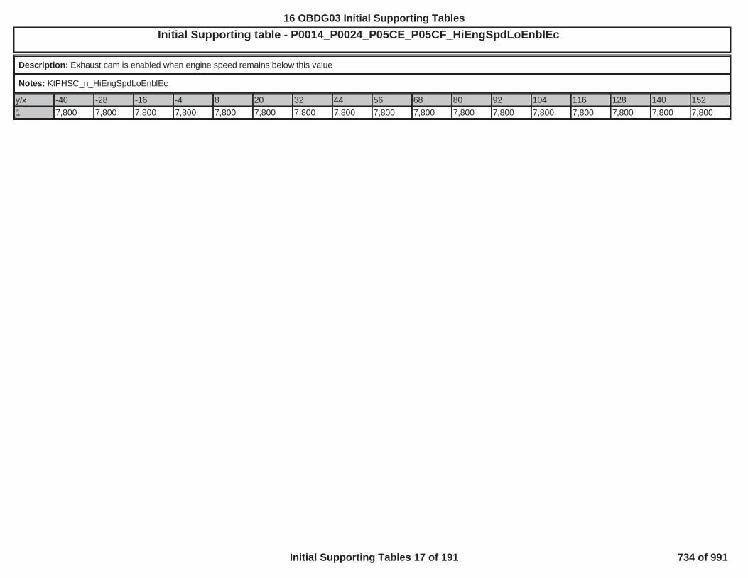
Initial Supporting table - P0014_P0024_P05CE_P05CF_HiEngSpdLoEnblEcOBD GROUP:OBD GROUP: TESTTEST GROUP: G --BIN4, FED---BIN4EMISSIONS STDS: Bin 4
Description: Exhaust cam is enabled when engine speed remains below this value
Notes: KtPHSC_n_HiEngSpdLoEnblEc
y/x -40 -28 -16 -4 8 20 32 44 56 68 80 92 104 116 128 140 1521 7,800 7,800 7,800 7,800 7,800 7,800 7,800 7,800 7,800 7,800 7,800 7,800 7,800 7,800 7,800 7,800 7,800
512
16 OBDG03 Initial Supporting Tables
Initial Supporting Tables 17 of 191 734 of 991

Initial Supporting table - P0014_P0024_P05CE_P05CF_LoPresHiEnblEcOBD GROUP:OBD GROUP: TESTTEST GROUP: GGMXT0 IN4, FED---BIN4EMISSIONS STDS: Bin 4
Description: Exhaust cam is enabled when oil pressure exceeds this value
Notes: KtPHSC_p_LoPresHiEnblIc
y/x -40 -28 -16 -4 8 20 32 44 56 68 80 92 104 116 128 140 152
1 100 100 100 100 100 100 100 100 100 100 100 100 100 100 100 100 100
513
16 OBDG03 Initial Supporting Tables
Initial Supporting Tables 18 of 191 735 of 991

Initial Supporting table - P0014_P0024_P05CE_P05CF_LoPresLoDsblEcOBD GROUP:OBD GROUP: TESTTEST GROUP: G FED---BIN4EMISSIONS STDS: Bin 4
Description: Exhaust cam is disabled when oil pressure falls below this value
Notes: KtPHSC_p_LoPresLoDsblEc
y/x -40 -28 -16 -4 8 20 32 44 56 68 80 92 104 116 128 140 152
1 100 100 100 100 100 100 100 100 100 100 100 100 100 100 100 100 100
514
16 OBDG03 Initial Supporting Tables
Initial Supporting Tables 19 of 191 736 of 991

Initial Supporting table - P0014_P0024_P05CE_P05CF_LoRpmHiEnblEcOBD GROUP:OBD GROUP: TESTTEST GROUP: G 4, FED---BIN4EMISSIONS STDS: Bin 4
Description: Exhaust cam is enabled when engine speed exceeds this value.
Notes: KtPHSC_n_LoRpmHiEnblEc
y/x -40 -28 -16 -4 8 20 32 44 56 68 80 92 104 116 128 140 1521 400 400 400 400 450 450 450 450 450 450 450 450 450 1,200 1,400 1,650 7,600
515
16 OBDG03 Initial Supporting Tables
Initial Supporting Tables 20 of 191 737 of 991

Initial Supporting table - P0014_P0024_P05CE_P05CF_LoRpmLoDsblEcOBD GROUP:OBD GROUP: TESTTEST GROUP: G 4, FED---BIN4EMISSIONS STDS: Bin 4
Description: Exhaust cam is disabled when engine speed is below this value.
Notes: KtPHSC_n_LoRpmLoDsblEc
y/x -40 -28 -16 -4 8 20 32 44 56 68 80 92 104 116 128 140 1521 300 300 300 300 350 350 350 350 350 350 350 350 350 1,100 1,300 1,550 7,500
516
16 OBDG03 Initial Supporting Tables
Initial Supporting Tables 21 of 191 738 of 991

Initial Supporting table - P0014_P05CE_StablePositionTimeEc1OBD GROUP:OBD GROUP: TESTTEST GROUP: G -BIN4, FED---BIN4EMISSIONS STDS: Bin 4
Description: P0014 - Delay after transient move
Notes: KtPHSD_t_StablePositionTimeEc1
y/x -40 -28 -16 -4 8 20 32 44 56 68 80 92 104 116 128 140 152
400 100.0 80.0 6.0 3.0 3.0 3.0 3.0 3.0 3.0 3.0 3.0 3.0 3.0 3.0 3.0 3.0 3.0
800 100.0 80.0 6.0 3.0 3.0 3.0 3.0 3.0 3.0 3.0 3.0 3.0 3.0 3.0 3.0 3.0 3.0
1,200 100.0 80.0 6.0 3.0 3.0 3.0 3.0 3.0 3.0 3.0 3.0 3.0 3.0 3.0 3.0 3.0 3.0
1,600 100.0 80.0 6.0 3.0 3.0 3.0 3.0 3.0 3.0 3.0 3.0 3.0 3.0 3.0 3.0 3.0 3.0
2,000 100.0 80.0 6.0 3.0 3.0 3.0 3.0 3.0 3.0 3.0 3.0 3.0 3.0 3.0 3.0 3.0 3.0
2,400 100.0 80.0 6.0 3.0 3.0 3.0 3.0 3.0 3.0 3.0 3.0 3.0 3.0 3.0 3.0 3.0 3.0
2,800 100.0 80.0 6.0 3.0 3.0 3.0 3.0 3.0 3.0 3.0 3.0 3.0 3.0 3.0 3.0 3.0 3.0
3,200 100.0 80.0 6.0 3.0 3.0 3.0 3.0 3.0 3.0 3.0 3.0 3.0 3.0 3.0 3.0 3.0 3.0
3,600 100.0 80.0 6.0 3.0 3.0 3.0 3.0 3.0 3.0 3.0 3.0 3.0 3.0 3.0 3.0 3.0 3.0
4,000 100.0 80.0 6.0 3.0 3.0 3.0 3.0 3.0 3.0 3.0 3.0 3.0 3.0 3.0 3.0 3.0 3.0
4,400 100.0 80.0 6.0 3.0 3.0 3.0 3.0 3.0 3.0 3.0 3.0 3.0 3.0 3.0 3.0 3.0 3.0
4,800 100.0 80.0 6.0 3.0 3.0 3.0 3.0 3.0 3.0 3.0 3.0 3.0 3.0 3.0 3.0 3.0 3.0
5,200 100.0 80.0 6.0 3.0 3.0 3.0 3.0 3.0 3.0 3.0 3.0 3.0 3.0 3.0 3.0 3.0 3.0
5,600 100.0 80.0 6.0 3.0 3.0 3.0 3.0 3.0 3.0 3.0 3.0 3.0 3.0 3.0 3.0 3.0 3.0
6,000 100.0 80.0 6.0 3.0 3.0 3.0 3.0 3.0 3.0 3.0 3.0 3.0 3.0 3.0 3.0 3.0 3.0
6,400 100.0 80.0 6.0 3.0 3.0 3.0 3.0 3.0 3.0 3.0 3.0 3.0 3.0 3.0 3.0 3.0 3.0
6,800 100.0 80.0 6.0 3.0 3.0 3.0 3.0 3.0 3.0 3.0 3.0 3.0 3.0 3.0 3.0 3.0 3.0
517
16 OBDG03 Initial Supporting Tables
Initial Supporting Tables 22 of 191 739 of 991

Initial Supporting table - P0016, P0017, P0018, P0019: Cam Correlation Oil Temperature ThresholdOBD GROUP:OBD GROUP: TESTTEST GROUP: G , FED---BIN4EMISSIONS STDS: Bin 4
Description: P0016_P0017_P0018_P0019 Cam Correlation Oil Temperature Threshold
Notes: KtEPSI_t_RtnHomeDlyLmt
y/x -40 -28 -16 -4 8 20 32 44 56 68 80 92 104 116 128 140 1521 300.0 300.0 160.0 18.0 18.0 18.0 18.0 10.0 3.0 3.0 3.0 3.0 3.0 3.0 3.0 3.0 3.0
518
16 OBDG03 Initial Supporting Tables
Initial Supporting Tables 23 of 191 740 of 991

Initial Supporting table - P0071: OAT Performance Drive Equilibrium Engine OffOBD GROUP:OBD GROUP: TESTTEST GROUP: G DS: Bin 4
Description: OAT Performance Diagnostic counter increment for determining OAT-IAT equilibrium for engine off (for hybrid applications)
Notes:
y/x 0.0 5.0 10.0 15.0 20.0 25.0 30.0 50.0 80.0
1.0 0.0 1.0 2.0 3.0 4.0 5.0 6.0 7.0 8.0
519
16 OBDG03 Initial Supporting Tables
Initial Supporting Tables 24 of 191 741 of 991

Initial Supporting table - P0071: OAT Performance Drive Equilibrium Engine RunningOBD GROUP: D2UB LTGOBD GROUP: GGMXOBDG03 FED---BIN4EMISSIONS STDS: Bin 4
Description: OAT Performance Diagnostic counter increment for determining OAT-IAT equilibrium for engine running
Notes:
y/x 0.0 5.0 10.0 15.0 20.0 25.0 30.0 50.0 80.01.0 1.0 2.0 3.0 4.0 5.0 6.0 7.0 8.0 9.05.0 -5.0 -2.0 -1.0 0.0 1.0 2.0 3.0 4.0 5.010.0 -4.0 -1.0 0.0 0.0 1.0 2.0 3.0 4.0 5.020.0 -2.0 -1.0 0.0 0.0 1.0 2.0 3.0 4.0 5.030.0 -1.0 0.0 0.0 1.0 2.0 3.0 4.0 5.0 6.040.0 0.0 0.0 0.0 1.0 2.0 3.0 4.0 5.0 6.050.0 0.0 0.0 1.0 2.0 3.0 4.0 5.0 6.0 7.060.0 0.0 1.0 2.0 3.0 4.0 5.0 6.0 7.0 8.070.0 1.0 2.0 3.0 4.0 5.0 6.0 7.0 8.0 9.0
520
16 OBDG03 Initial Supporting Tables
Initial Supporting Tables 25 of 191 742 of 991

Initial Supporting table - P00C4_P2261_KtBSTD_r_SurgeLimOBD GROUP:OBD GROUP: TESTTEST GROUP: GG N4, FED---BIN4EMISSIONS STDS: Bin 4
Description: Turbo compressor bypass valve diagnosis surge area limit.
Notes: X-Axis: KnBSTD_dm_AirFlowBP - Air FLow
y/x 0.00 38.09 76.63 100.00 143.52 189.111.0 1.000 1.500 2.444 2.700 3.100 3.412
521
16 OBDG03 Initial Supporting Tables
Initial Supporting Tables 26 of 191 743 of 991

Initial Supporting table - P0101, P0106, P010B, P0121, P0236, P1101: Turbocharger Intake Flow Rationality Diagnostic Failure Matrix4, FED---BIN4EMISSIONS STDS: Bin 4
Description: Turbocharger Intake Flow Rationality Diagnostic Failure Matrix
Notes: This table describes combinations of individual model failures that will set P0101, P0106, P010B, P0121, P0236 and P1101 on turbocharged applications.
y/x 1 2 3 4 5 6 7 8 91 MAF Model MAP1 Model MAP2 Model MAP3 Model TIAP1 Model TPS Model TIAP Correlation TIAP Correlation DTC Set2 Failed Failed Failed Failed Failed Failed Failed Valid3 F F F F F F F F No DTC4 F F F F F F F T No DTC5 F F F F F F T F No DTC6 F F F F F F T T No DTC7 F F F F F T F F No DTC8 F F F F F T F T No DTC9 F F F F F T T F No DTC10 F F F F F T T T No DTC11 F F F F T F F F No DTC12 F F F F T F F T No DTC13 F F F F T F T F No DTC14 F F F F T F T T No DTC15 F F F F T T F F P110116 F F F F T T F T P012117 F F F F T T T F P110118 F F F F T T T T P023619 F F F T F F F F P110120 F F F T F F F T P110121 F F F T F F T F P110122 F F F T F F T T P110123 F F F T F T F F P110124 F F F T F T F T P110125 F F F T F T T F P110126 F F F T F T T T P110127 F F F T T F F F P110128 F F F T T F F T P110129 F F F T T F T F P110130 F F F T T F T T P110131 F F F T T T F F P110132 F F F T T T F T P110133 F F F T T T T F P110134 F F F T T T T T P1101
522
16 OBDG03 Initial Supporting Tables
Initial Supporting Tables 27 of 191 744 of 991

Initial Supporting table - P0101, P0106, P010B, P0121, P0236, P1101: Turbocharger Intake Flow Rationality Diagnostic Failure MatrixOBD GROUP:OBD GROUP: TESTTEST GROUP: G FED---BIN4EMISSIONS STDS: Bin 435 F F T F F F F F P110136 F F T F F F F T P110137 F F T F F F T F P110138 F F T F F F T T P110139 F F T F F T F F P110140 F F T F F T F T P110141 F F T F F T T F P110142 F F T F F T T T P110143 F F T F T F F F P110144 F F T F T F F T P110145 F F T F T F T F P110146 F F T F T F T T P110147 F F T F T T F F P110148 F F T F T T F T P110149 F F T F T T T F P110150 F F T F T T T T P110151 F F T T F F F F P110152 F F T T F F F T P110153 F F T T F F T F P110154 F F T T F F T T P110155 F F T T F T F F P110156 F F T T F T F T P110157 F F T T F T T F P110158 F F T T F T T T P110159 F F T T T F F F No DTC60 F F T T T F F T No DTC61 F F T T T F T F No DTC62 F F T T T F T T No DTC63 F F T T T T F F P110164 F F T T T T F T P110165 F F T T T T T F P110166 F F T T T T T T P110167 F T F F F F F F P110168 F T F F F F F T P110169 F T F F F F T F P110170 F T F F F F T T P023671 F T F F F T F F P110172 F T F F F T F T P0121
523
16 OBDG03 Initial Supporting Tables
Initial Supporting Tables 28 of 191 745 of 991

Initial Supporting table - P0101, P0106, P010B, P0121, P0236, P1101: Turbocharger Intake Flow Rationality Diagnostic Failure MatrixOBD GROUP:OBD GROUP: TESTTEST GROUP: G DS: Bin 473 F T F F F T T F P110174 F T F F F T T T P023675 F T F F T F F F P110176 F T F F T F F T P110177 F T F F T F T F P110178 F T F F T F T T P023679 F T F F T T F F P110180 F T F F T T F T P012181 F T F F T T T F P110182 F T F F T T T T P023683 F T F T F F F F P110184 F T F T F F F T P110185 F T F T F F T F P110186 F T F T F F T T P110187 F T F T F T F F P110188 F T F T F T F T P110189 F T F T F T T F P110190 F T F T F T T T P110191 F T F T T F F F P110192 F T F T T F F T P110193 F T F T T F T F P110194 F T F T T F T T P110195 F T F T T T F F P110196 F T F T T T F T P110197 F T F T T T T F P110198 F T F T T T T T P110199 F T T F F F F F P1101100 F T T F F F F T P1101101 F T T F F F T F P1101102 F T T F F F T T P1101103 F T T F F T F F P1101104 F T T F F T F T P1101105 F T T F F T T F P1101106 F T T F F T T T P1101107 F T T F T F F F P1101108 F T T F T F F T P1101109 F T T F T F T F P1101110 F T T F T F T T P1101
524
16 OBDG03 Initial Supporting Tables
Initial Supporting Tables 29 of 191 746 of 991

Initial Supporting table - P0101, P0106, P010B, P0121, P0236, P1101: Turbocharger Intake Flow Rationality Diagnostic Failure MatrixOBD GROUP:OBD GROUP: TESTTEST GROUP: G TDS: Bin 4111 F T T F T T F F P1101112 F T T F T T F T P1101113 F T T F T T T F P1101114 F T T F T T T T P1101115 F T T T F F F F P0106116 F T T T F F F T P0106117 F T T T F F T F P0106118 F T T T F F T T P0106119 F T T T F T F F P1101120 F T T T F T F T P1101121 F T T T F T T F P1101122 F T T T F T T T P1101123 F T T T T F F F P1101124 F T T T T F F T P1101125 F T T T T F T F P1101126 F T T T T F T T P1101127 F T T T T T F F P1101128 F T T T T T F T P1101129 F T T T T T T F P1101130 F T T T T T T T P1101131 T F F F F F F F P1101132 T F F F F F F T P1101133 T F F F F F T F P1101134 T F F F F F T T P0236135 T F F F F T F F P1101136 T F F F F T F T P0121137 T F F F F T T F P1101138 T F F F F T T T P0236139 T F F F T F F F P1101140 T F F F T F F T P1101141 T F F F T F T F P1101142 T F F F T F T T P0236143 T F F F T T F F P1101144 T F F F T T F T P0121145 T F F F T T T F P1101146 T F F F T T T T P0236147 T F F T F F F F P1101148 T F F T F F F T P1101
525
16 OBDG03 Initial Supporting Tables
Initial Supporting Tables 30 of 191 747 of 991

Initial Supporting table - P0101, P0106, P010B, P0121, P0236, P1101: Turbocharger Intake Flow Rationality Diagnostic Failure MatrixOBD GROUP:OBD GROUP: TESTTEST GROUP: G 4, FED---BIN4EMISSIONS STDS: Bin 4
149 T F F T F F T F P1101150 T F F T F F T T P1101151 T F F T F T F F P1101152 T F F T F T F T P1101153 T F F T F T T F P1101154 T F F T F T T T P1101155 T F F T T F F F P1101156 T F F T T F F T P1101157 T F F T T F T F P1101158 T F F T T F T T P1101159 T F F T T T F F P1101160 T F F T T T F T P1101161 T F F T T T T F P1101162 T F F T T T T T P1101163 T F T F F F F F P1101164 T F T F F F F T P1101165 T F T F F F T F P1101166 T F T F F F T T P1101167 T F T F F T F F P1101168 T F T F F T F T P1101169 T F T F F T T F P1101170 T F T F F T T T P1101171 T F T F T F F F P1101172 T F T F T F F T P1101173 T F T F T F T F P1101174 T F T F T F T T P1101175 T F T F T T F F P1101176 T F T F T T F T P1101177 T F T F T T T F P1101178 T F T F T T T T P1101179 T F T T F F F F P1101180 T F T T F F F T P1101181 T F T T F F T F P1101182 T F T T F F T T P1101183 T F T T F T F F P1101184 T F T T F T F T P1101185 T F T T F T T F P1101186 T F T T F T T T P1101
526
16 OBDG03 Initial Supporting Tables
Initial Supporting Tables 31 of 191 748 of 991

Initial Supporting table - P0101, P0106, P010B, P0121, P0236, P1101: Turbocharger Intake Flow Rationality Diagnostic Failure MatrixOBD GROUP:OBD GROUP: TESTTEST GROUP: G BIN4, FED---BIN4EMISSIONS STDS: Bin 4187 T F T T T F F F P0101 or P010B188 T F T T T F F T P0101 or P010B189 T F T T T F T F P0101 or P010B190 T F T T T F T T P0101 or P010B191 T F T T T T F F P1101192 T F T T T T F T P1101193 T F T T T T T F P1101194 T F T T T T T T P1101195 T T F F F F F F P1101196 T T F F F F F T P1101197 T T F F F F T F P1101198 T T F F F F T T P0236199 T T F F F T F F P1101200 T T F F F T F T P0121201 T T F F F T T F P1101202 T T F F F T T T P0236203 T T F F T F F F P1101204 T T F F T F F T P1101205 T T F F T F T F P1101206 T T F F T F T T P0236207 T T F F T T F F P1101208 T T F F T T F T P0121209 T T F F T T T F P1101210 T T F F T T T T P0236211 T T F T F F F F P1101212 T T F T F F F T P1101213 T T F T F F T F P1101214 T T F T F F T T P1101215 T T F T F T F F P1101216 T T F T F T F T P1101217 T T F T F T T F P1101218 T T F T F T T T P1101219 T T F T T F F F P1101220 T T F T T F F T P1101221 T T F T T F T F P1101222 T T F T T F T T P1101223 T T F T T T F F P1101224 T T F T T T F T P1101
527
16 OBDG03 Initial Supporting Tables
Initial Supporting Tables 32 of 191 749 of 991

Initial Supporting table - P0101, P0106, P010B, P0121, P0236, P1101: Turbocharger Intake Flow Rationality Diagnostic Failure MatrixOBD GROUP:OBD GROUP: TESTTEST GROUP: G FED---BIN4EMISSIONS STDS: Bin 4225 T T F T T T T F P1101226 T T F T T T T T P1101227 T T T F F F F F P1101228 T T T F F F F T P1101229 T T T F F F T F P1101230 T T T F F F T T P1101231 T T T F F T F F P1101232 T T T F F T F T P1101233 T T T F F T T F P1101234 T T T F F T T T P1101235 T T T F T F F F P1101236 T T T F T F F T P1101237 T T T F T F T F P1101238 T T T F T F T T P1101239 T T T F T T F F P1101240 T T T F T T F T P1101241 T T T F T T T F P1101242 T T T F T T T T P1101243 T T T T F F F F P1101244 T T T T F F F T P1101245 T T T T F F T F P1101246 T T T T F F T T P1101247 T T T T F T F F P1101248 T T T T F T F T P1101249 T T T T F T T F P1101250 T T T T F T T T P1101251 T T T T T F F F P1101252 T T T T T F F T P1101253 T T T T T F T F P1101254 T T T T T F T T P1101255 T T T T T T F F P1101256 T T T T T T F T P1101257 T T T T T T T F P1101258 T T T T T T T T P1101
528
16 OBDG03 Initial Supporting Tables
Initial Supporting Tables 33 of 191 750 of 991

Initial Supporting table - P0101, P0106, P0121, P012B, P0236, P1101: MAP1 Residual Weight Factor based on RPMOBD GROUP:OBD GROUP: TESTTEST GROUP: G -BIN4, FED---BIN4EMISSIONS STDS: Bin 4
Description: P0101_P0106_P0121_P012B_P0236_P1101 MAP1 Residual Weight Factor based on RPM
Notes:
y/x 0 400 800 1,200 1,600 2,000 2,400 2,800 3,200 3,600 4,000 4,400 4,800 5,200 5,600 6,000 6,200
1 1.000 1.000 1.000 1.000 1.000 1.000 1.000 1.000 1.000 1.000 1.000 1.000 1.000 1.000 1.000 1.000 1.000
529
16 OBDG03 Initial Supporting Tables
Initial Supporting Tables 34 of 191 751 of 991

Initial Supporting table - P0101, P0106, P0121, P012B, P0236, P1101: MAP2 Residual Weight Factor based on RPMOBD GROUP:OBD GROUP: TESTTEST GROUP: G FED---BIN4EMISSIONS STDS: Bin 4
Description: P0101_P0106_P0121_P012B_P0236_P1101 MAP2 Residual Weight Factor based on RPM
Notes:
y/x 0 400 800 1,200 1,600 2,000 2,400 2,800 3,200 3,600 4,000 4,400 4,800 5,200 5,600 6,000 6,2001 1.000 1.000 1.000 1.000 0.857 0.896 0.800 0.999 1.000 0.950 0.950 0.950 0.950 0.950 0.950 0.950 0.950
530
16 OBDG03 Initial Supporting Tables
Initial Supporting Tables 35 of 191 752 of 991

Initial Supporting table - P0101, P0106, P0121, P012B, P0236, P1101: MAP3 Residual Weight Factor based on RPMOBD GROUP:OBD GROUP: G TESTTEST GROUP: G BIN4, FED---BIN4EMISSIONS STDS: Bin 4
Description: P0101_P0106_P0121_P012B_P0236_P1101 MAP3 Residual Weight Factor based on RPM
Notes:
y/x 0 400 800 1,200 1,600 2,000 2,400 2,800 3,200 3,600 4,000 4,400 4,800 5,200 5,600 6,000 6,200
1 1.000 1.000 1.000 1.000 0.864 0.889 0.800 1.000 1.000 0.880 0.880 0.880 0.880 0.880 0.880 0.880 0.880
531
16 OBDG03 Initial Supporting Tables
Initial Supporting Tables 36 of 191 753 of 991

Initial Supporting table - P0101, P0106, P0121, P012B, P0236, P1101: TPS Residual Weight Factor based on RPMOBD GROUP:OBD GROUP: TESTTEST GROUP: G 4, FED---BIN4EMISSIONS STDS: Bin 4
Description: P0101_P0106_P0121_P012B_P0236_P1101 TPS Residual Weight Factor based on RPM
Notes:
y/x 0 400 800 1,200 1,600 2,000 2,400 2,800 3,200 3,600 4,000 4,400 4,800 5,200 5,600 6,000 6,200
1 1.000 1.000 1.000 1.000 1.000 1.000 1.000 1.000 1.000 1.000 1.000 1.000 1.000 1.000 1.000 1.000 1.000
532
16 OBDG03 Initial Supporting Tables
Initial Supporting Tables 37 of 191 754 of 991

Initial Supporting table - P0101, P0106, P0121, P0236, P1101: TIAP Residual Weight Factor based on RPMOBD GROUP:OBD GROUP: TESTTEST GROUP: G --BIN4, FED---BIN4EMISSIONS STDS: Bin 4
Description: P0101_P0106_P0121_P0236_P1101 TIAP Residual Weight Factor based on RPM
Notes:
y/x 0 400 800 1,200 1,600 2,000 2,400 2,800 3,200 3,600 4,000 4,400 4,800 5,200 5,600 6,000 6,2001 1.000 0.700 0.600 1.000 1.000 0.990 0.900 0.947 0.928 0.800 0.800 0.800 0.800 0.800 0.800 0.800 0.800
533
16 OBDG03 Initial Supporting Tables
Initial Supporting Tables 38 of 191 755 of 991

Initial Supporting table - P0101, P0106, P0121, P0236, P1101: TIAP-Baro Correlation Max Air FlowOBD GROUP:OBD GROUP: TESTTEST GROUP: G IN4, FED---BIN4EMISSIONS STDS: Bin 4
Description: P0101_P0106_P0121_P0236_P1101 TIAP-Baro Correlation Max Air Flow
Notes:
y/x 1,000 1,750 2,500 3,250 4,000 4,750 5,500 6,250 7,000
1 13.0 13.0 13.0 16.0 20.0 24.0 28.0 31.0 32.0
534
16 OBDG03 Initial Supporting Tables
Initial Supporting Tables 39 of 191 756 of 991

Initial Supporting table - P0101, P0106, P0121, P0236, P1101: TIAP-Baro Correlation Max MAPOBD GROUP:OBD GROUP: TESTTEST GROUP: G BIN4, FED---BIN4EMISSIONS STDS: Bin 4
Description: P0101_P0106_P0121_P0236_P1101 TIAP-Baro Correlation Max MAP
Notes:
y/x 1,000 1,750 2,500 3,250 4,000 4,750 5,500 6,250 7,000
1 70.0 70.0 70.0 70.0 70.0 70.0 70.0 70.0 70.0
535
16 OBDG03 Initial Supporting Tables
Initial Supporting Tables 40 of 191 757 of 991

Initial Supporting table - P0101, P0106, P0121, P0236, P1101: TIAP-Baro Correlation OffsetOBD GROUP:OBD GROUP: GGMXO TESTTEST GROUP: G , FED---BIN4EMISSIONS STDS: Bin 4
Description: P0101_P0106_P0121_P0236_P1101 TIAP-Baro Correlation Offset
Notes:
y/x 1,000 1,750 2,500 3,250 4,000 4,750 5,500 6,250 7,000
1 0.0 1.5 3.5 6.0 9.0 12.0 16.0 20.0 25.0
536
16 OBDG03 Initial Supporting Tables
Initial Supporting Tables 41 of 191 758 of 991

Initial Supporting table - P0101, P0106, P0121, P0236, P1101: TIAP-MAP Correlation Min Air FlowOBD GROUP:OBD GROUP: TESTTEST GROUP: GGM --BIN4, FED---BIN4EMISSIONS STDS: Bin 4
Description: P0101_P0106_P0121_P0236_P1101 TIAP-MAP Correlation Min Air Flow
Notes:
y/x 1,000 1,750 2,500 3,250 4,000 4,750 5,500 6,250 7,0001 17.0 43.0 92.0 120.0 164.0 189.0 195.0 189.0 192.0
537
16 OBDG03 Initial Supporting Tables
Initial Supporting Tables 42 of 191 759 of 991

Initial Supporting table - P0101, P0106, P0121, P0236, P1101: TIAP-MAP Correlation Min MAPOBD GROUP:OBD GROUP: G TESTTEST GROUP: G IN4, FED---BIN4EMISSIONS STDS: Bin 4
Description: P0101_P0106_P0121_P0236_P1101 TIAP-MAP Correlation Min MAP
Notes:
y/x 1,000 1,750 2,500 3,250 4,000 4,750 5,500 6,250 7,000
1 110.0 152.0 212.2 213.0 221.0 206.0 192.0 166.0 166.0
538
16 OBDG03 Initial Supporting Tables
Initial Supporting Tables 43 of 191 760 of 991
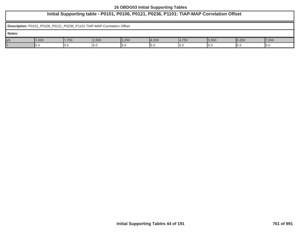
Initial Supporting table - P0101, P0106, P0121, P0236, P1101: TIAP-MAP Correlation OffsetOBD GROUP:OBD GROUP: TESTTEST GROUP: G L---BIN4, FED---BIN4EMISSIONS STDS: Bin 4
Description: P0101_P0106_P0121_P0236_P1101 TIAP-MAP Correlation Offset
Notes:
y/x 1,000 1,750 2,500 3,250 4,000 4,750 5,500 6,250 7,000
1 5.0 5.0 5.0 5.0 5.0 5.0 5.0 5.0 5.0
539
16 OBDG03 Initial Supporting Tables
Initial Supporting Tables 44 of 191 761 of 991

Initial Supporting table - P0234_KtBSTD_p_CntrlDevNegLimOBD GROUP:OBD GROUP: TESTTEST GROUP: G BIN4, FED---BIN4EMISSIONS STDS: Bin 4
Description: Negative boost pressure control deviation fail limit.
Notes: X-Axis: KnBSTD_p_CntrlDevDiagDsrdBP - Boost pressureY-Axis: KnBSTD_n_CntrlDevDiagEngSpdBP - Engine speed
y/x 5.00 50.00 100.00 120.00 140.00 160.00 180.00 200.00 250.00 300.00
1,000 -100.00 -100.00 -100.00 -100.00 -100.00 -100.00 -100.00 -100.00 -100.00 -100.00
1,500 -100.00 -80.00 -80.00 -80.00 -80.00 -80.00 -80.00 -80.00 -80.00 -80.00
2,000 -100.00 -30.00 -30.00 -30.00 -30.00 -30.00 -30.00 -30.00 -30.00 -30.00
2,500 -100.00 -30.00 -30.00 -30.00 -30.00 -30.00 -30.00 -30.00 -30.00 -30.00
3,000 -100.00 -30.00 -30.00 -30.00 -30.00 -30.00 -30.00 -30.00 -30.00 -30.00
3,500 -100.00 -30.00 -30.00 -30.00 -30.00 -30.00 -30.00 -30.00 -30.00 -30.00
4,000 -100.00 -30.00 -30.00 -30.00 -30.00 -30.00 -30.00 -30.00 -30.00 -30.00
4,500 -100.00 -30.00 -30.00 -30.00 -30.00 -30.00 -30.00 -30.00 -30.00 -30.00
5,000 -100.00 -30.00 -30.00 -30.00 -30.00 -30.00 -30.00 -30.00 -30.00 -30.00
6,000 -100.00 -30.00 -30.00 -30.00 -30.00 -30.00 -30.00 -30.00 -30.00 -30.00
540
16 OBDG03 Initial Supporting Tables
Initial Supporting Tables 45 of 191 762 of 991

Initial Supporting table - P0234_P0299_KtBSTD_p_CntrlDevAmbAirCorrOBD GROUP:OBD GROUP: GG TESTTEST GROUP: G -BIN4, FED---BIN4EMISSIONS STDS: Bin 4
Description: Additative offset on boost pressure control deviation fail limit.
Notes: X-Axis: KnBSTD_p_CntrlDevDiagAmbCorrBP - Ambient Air PressureY-Axis: KnBSTD_n_CntrlDevDiagAmbCorrBP - Engine Speed
y/x 60.00 70.00 80.00 90.00 100.00 110.001,500 130.00 130.00 130.00 130.00 130.00 130.002,500 125.00 120.00 90.00 55.00 0.00 0.003,000 115.00 105.00 75.00 35.00 0.00 0.004,000 65.00 60.00 50.00 25.00 0.00 0.005,000 30.00 25.00 20.00 10.00 0.00 0.006,000 0.00 0.00 0.00 0.00 0.00 0.00
541
16 OBDG03 Initial Supporting Tables
Initial Supporting Tables 46 of 191 763 of 991

Initial Supporting table - P0234_P0299_KtBSTD_t_CntrlDevEnblDelayOBD GROUP:OBD GROUP: GGMXOBDG0LTG TESTTEST GROUP: GGM AL---BIN4, FED---BIN4EMISSIONS STDS: Bin 4
Description: Timer to stabilize enable conditions for over and underboost diagnosis.
Notes: X-Axis: KnBSTD_n_CntrlDevDiagEngSpdBP - Engine Speed
y/x 1,000 1,500 2,000 2,500 3,000 3,500 4,000 4,500 5,000 6,000
1 1.7500 1.5000 1.3750 1.1250 1.0000 0.8750 0.7500 0.6250 0.5000 0.5000
542
16 OBDG03 Initial Supporting Tables
Initial Supporting Tables 47 of 191 764 of 991

Initial Supporting table - P0299_KtBSTD_p_CntrlDevPosLimOBD GROUP:OBD GROUP: TESTTEST GROUP: G --BIN4, FED---BIN4EMISSIONS STDS: Bin 4
Description: Positive boost pressure control deviation fail limit.
Notes: X-Axis: KnBSTD_p_CntrlDevDiagDsrdBP - Boost pressureY-Axis: KnBSTD_n_CntrlDevDiagEngSpdBP - Engine speed
y/x 5.00 50.00 100.00 120.00 140.00 160.00 180.00 200.00 250.00 300.001,000 100.00 100.00 100.00 100.00 100.00 100.00 100.00 100.00 100.00 100.001,500 100.00 80.00 80.00 80.00 80.00 80.00 80.00 80.00 80.00 130.002,000 100.00 80.00 80.00 75.00 40.00 40.00 40.00 50.00 80.00 120.002,500 100.00 80.00 80.00 75.00 40.00 40.00 40.00 40.00 60.00 90.003,000 100.00 80.00 80.00 75.00 40.00 40.00 40.00 40.00 40.00 80.003,500 100.00 50.00 50.00 50.00 40.00 40.00 40.00 40.00 40.00 80.004,000 100.00 30.00 30.00 30.00 30.00 30.00 30.00 30.00 40.00 80.004,500 100.00 30.00 30.00 30.00 30.00 30.00 30.00 30.00 40.00 80.005,000 100.00 30.00 30.00 30.00 30.00 30.00 30.00 30.00 40.00 80.006,000 100.00 30.00 30.00 30.00 30.00 30.00 30.00 30.00 40.00 80.00
543
16 OBDG03 Initial Supporting Tables
Initial Supporting Tables 48 of 191 765 of 991

Initial Supporting table - VCE_ECOMode_EnableTorqueHystOBD GROUP:OBD GROUP: GGM TESTTEST GROUP: GG IN4, FED---BIN4EMISSIONS STDS: Bin 4
Description: Entry threshold for torque based VCE mode selection when eco mode is active. VCE will be enabled for torque if the torque request is less than the max VCE torque minusthis calibration in Nm.
Notes: P3400: KaVCEC_M_EcoRedTrqEnterThrsh
VCE_ECOMode_EnableTorqueHyst - Part 1
y/x CeTGRR_e_TransGr1 CeTGRR_e_TransGr2 CeTGRR_e_TransGr3 CeTGRR_e_TransGr4 CeTGRR_e_TransGr5 CeTGRR_e_TransGr6 CeTGRR_e_TransGrEVT1
1 10 10 10 10 10 10 10
VCE_ECOMode_EnableTorqueHyst - Part 2
y/x CeTGRR_e_TransGrEVT2
CeTGRR_e_TransGrNeut
CeTGRR_e_TransGrRvrs
CeTGRR_e_TransGrPark
CeTGRR_e_TransGr7 CeTGRR_e_TransGr8
1 10 10 10 10 10 10
544
16 OBDG03 Initial Supporting Tables
Initial Supporting Tables 49 of 191 766 of 991

Initial Supporting table - VCE_ECOMode_MaxTorque_Gr5OBD GROUP:OBD GROUP: GG TESTTEST GROUP: G L---BIN4, FED---BIN4EMISSIONS STDS: Bin 4
Description: CeTGRR_e_TransGr5 maximum indicated torque (Nm) allowed in VCE mode when Eco Mode is active. Function of engine speed.
Notes: For P3400: KaVCEC_M_EcoRedTrqMaxIndThrsh
VCE_ECOMode_MaxTorque_Gr5 - Part 1
y/x 500 600 700 800 900 1,000 1,100 1,200 1,300 1,400 1,500 1,600 1,7001 8,192 8,192 8,192 8,192 8,192 8,192 8,192 8,192 8,192 8,192 8,192 8,192 8,192
VCE_ECOMode_MaxTorque_Gr5 - Part 2
y/x 1,800 1,900 2,000 2,100 2,200 2,300 2,400 2,500 2,600 2,700 2,800 2,900 3,0001 8,192 8,192 8,192 8,192 8,192 8,192 8,192 8,192 8,192 8,192 8,192 8,192 8,192
545
16 OBDG03 Initial Supporting Tables
Initial Supporting Tables 50 of 191 767 of 991

Initial Supporting table - VCE_EngineRPM_LowerLmtOBD GROUP:OBD GROUP: TESTTEST GROUP: G --BIN4, FED---BIN4EMISSIONS STDS: Bin 4
Description: Engine speed lower limit for AFM
Notes: For P3400: KaVCEC_n_EngineSpeedLowerLimit with axis defined by gear state. In VCE mode, engine speed less than this will force an exit. In non-VCE mode, engine speedgreater than this plus hysteresis enables VCE mode.
VCE_EngineRPM_LowerLmt - Part 1
y/x CeTGRR_e_TransGr1 CeTGRR_e_TransGr2 CeTGRR_e_TransGr3 CeTGRR_e_TransGr4 CeTGRR_e_TransGr5 CeTGRR_e_TransGr6 CeTGRR_e_TransGrEVT1
1 800 800 800 800 800 800 800
VCE_EngineRPM_LowerLmt - Part 2
y/x CeTGRR_e_TransGrEVT2
CeTGRR_e_TransGrNeut
CeTGRR_e_TransGrRvrs
CeTGRR_e_TransGrPark
CeTGRR_e_TransGr7 CeTGRR_e_TransGr8
1 800 800 800 800 800 800
546
16 OBDG03 Initial Supporting Tables
Initial Supporting Tables 51 of 191 768 of 991

Initial Supporting table - VCE_EngineRPM_UpperLmtOBD GROUP:OBD GROUP: TESTTEST GROUP: G --BIN4, FED---BIN4EMISSIONS STDS: Bin 4
Description: Engine speed upper limit for AFM
Notes: For P3400: KaVCEC_n_EngineSpeedUpperLimit: with axis defined by gear state. In VCE mode,engine speed greater than this will force an exit. In non-VCE mode, engine speedless than this minus hysteresis enables VCE mode.
VCE_EngineRPM_UpperLmt - Part 1
y/x CeTGRR_e_TransGr1 CeTGRR_e_TransGr2 CeTGRR_e_TransGr3 CeTGRR_e_TransGr4 CeTGRR_e_TransGr5 CeTGRR_e_TransGr6 CeTGRR_e_TransGrEVT1
1 3,100 3,100 3,100 3,100 3,100 3,100 3,100
VCE_EngineRPM_UpperLmt - Part 2
y/x CeTGRR_e_TransGrEVT2
CeTGRR_e_TransGrNeut
CeTGRR_e_TransGrRvrs
CeTGRR_e_TransGrPark
CeTGRR_e_TransGr7 CeTGRR_e_TransGr8
1 3,100 3,100 3,100 3,100 3,100 3,100
547
16 OBDG03 Initial Supporting Tables
Initial Supporting Tables 52 of 191 769 of 991

Initial Supporting table - VCE_MinVacReducedTorqModeOBD GROUP:OBD GROUP: GGMXOBDG TESTTEST GROUP: G 4, FED---BIN4EMISSIONS STDS: Bin 4
Description: Minimum Vacuum allowed in VCE mode
Notes: For P3400: KtVCEC_p_MinVacReducedTrqMode
VCE_MinVacReducedTorqMode - Part 1
y/x 500 600 700 800 900 1,000 1,100 1,200 1,3001 8.0 8.0 8.0 8.0 8.0 8.0 8.0 8.0 8.0
VCE_MinVacReducedTorqMode - Part 2
y/x 1,400 1,500 1,600 1,700 1,800 1,900 2,000 2,100 2,2001 7.0 6.0 6.0 6.0 6.0 6.0 6.0 6.0 6.0
VCE_MinVacReducedTorqMode - Part 3
y/x 2,300 2,400 2,500 2,600 2,700 2,800 2,900 3,0001 6.0 6.0 6.0 6.0 6.0 6.0 6.0 6.0
548
16 OBDG03 Initial Supporting Tables
Initial Supporting Tables 53 of 191 770 of 991

Initial Supporting table - VCE_NormalMode_EnableTorqueHystOBD GROUP:OBD GROUP: TESTTEST GROUP: G -BIN4, FED---BIN4EMISSIONS STDS: Bin 4
Description: Entry threshold for torque based VCE mode selection when eco mode is NOT active. VCE will be enabled for torque if the torque request is less than the max VCE torqueminus this calibration in Nm.
Notes: For P3400: KaVCEC_M_RedTrqEnterThrsh
VCE_NormalMode_EnableTorqueHyst - Part 1
y/x CeTGRR_e_TransGr1 CeTGRR_e_TransGr2 CeTGRR_e_TransGr3 CeTGRR_e_TransGr4 CeTGRR_e_TransGr5 CeTGRR_e_TransGr6 CeTGRR_e_TransGrEVT1
1 8 8 8 8 8 8 8
VCE_NormalMode_EnableTorqueHyst - Part 2
y/x CeTGRR_e_TransGrEVT2
CeTGRR_e_TransGrNeut
CeTGRR_e_TransGrRvrs
CeTGRR_e_TransGrPark
CeTGRR_e_TransGr7 CeTGRR_e_TransGr8
1 8 8 8 8 8 8
549
16 OBDG03 Initial Supporting Tables
Initial Supporting Tables 54 of 191 771 of 991
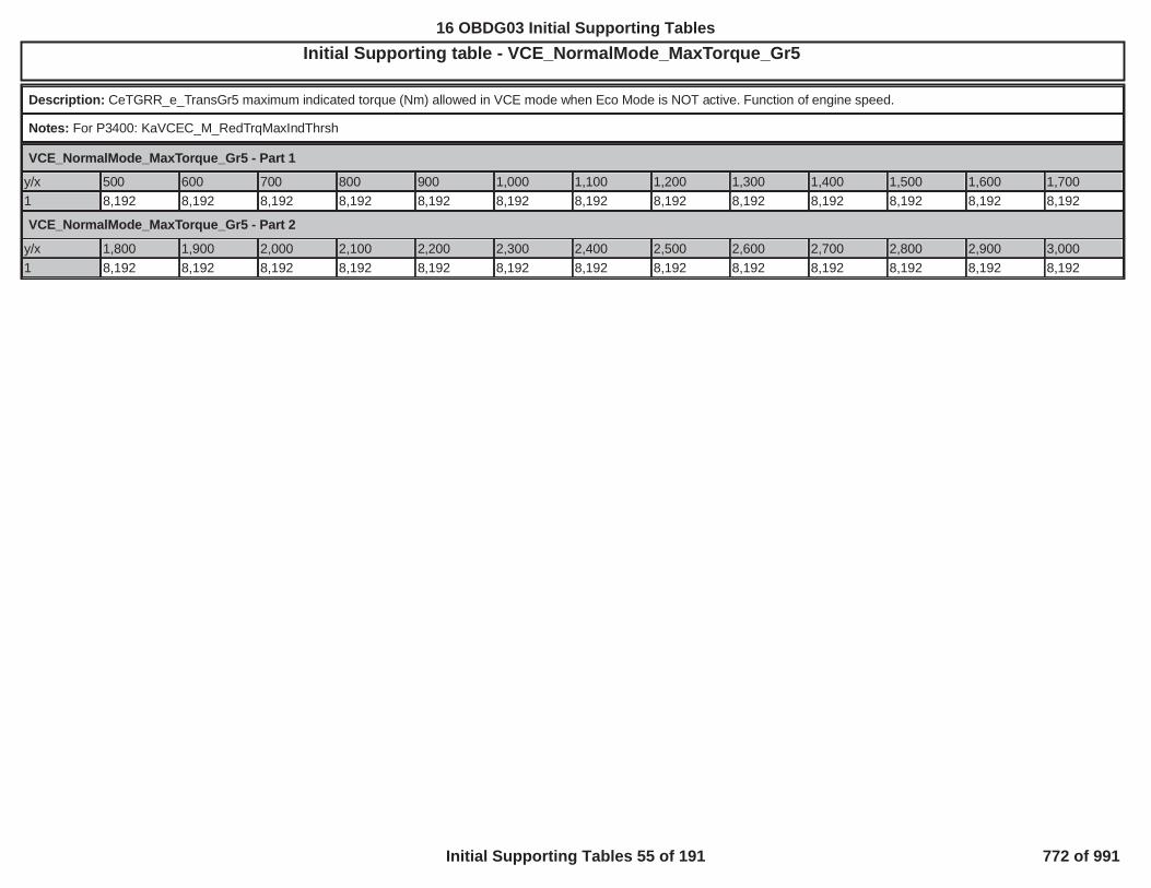
Initial Supporting table - VCE_NormalMode_MaxTorque_Gr5OBD GROUP:OBD GROUP: GGMXOBDG TESTTEST GROUP: GGMXT02.0 ---BIN4, FED---BIN4EMISSIONS STDS: Bin 4
Description: CeTGRR_e_TransGr5 maximum indicated torque (Nm) allowed in VCE mode when Eco Mode is NOT active. Function of engine speed.
Notes: For P3400: KaVCEC_M_RedTrqMaxIndThrsh
VCE_NormalMode_MaxTorque_Gr5 - Part 1
y/x 500 600 700 800 900 1,000 1,100 1,200 1,300 1,400 1,500 1,600 1,7001 8,192 8,192 8,192 8,192 8,192 8,192 8,192 8,192 8,192 8,192 8,192 8,192 8,192
VCE_NormalMode_MaxTorque_Gr5 - Part 2
y/x 1,800 1,900 2,000 2,100 2,200 2,300 2,400 2,500 2,600 2,700 2,800 2,900 3,0001 8,192 8,192 8,192 8,192 8,192 8,192 8,192 8,192 8,192 8,192 8,192 8,192 8,192
550
16 OBDG03 Initial Supporting Tables
Initial Supporting Tables 55 of 191 772 of 991

Initial Supporting table - VCE_PRNDL_NI_DisablesOBD GROUP:OBD GROUP: TESTTEST GROUP: G EM---BIN4, FED---BIN4EMISSIONS STDS: Bin 4
Description: Disables VCE mode in certain PRNDL positions when Neutral Idle Overrides (AFM at Idle) are active.
Notes: For P3400: KaVCEC_b_DisabledForPRNDL_NI
y/x 1 2 3 4 5 6 7 8 9 10 11 12 13 14 15 16 17 18 19 201 TRUE TRUE TRUE TRUE TRUE TRUE TRUE TRUE TRUE TRUE TRUE TRUE TRUE TRUE TRUE TRUE TRUE TRUE TRUE TRUE
551
16 OBDG03 Initial Supporting Tables
Initial Supporting Tables 56 of 191 773 of 991

Initial Supporting table - VCE_StartUpDelayTimeOBD GROUP:OBD GROUP: TESTTEST GROUP: G L---BIN4, FED---BIN4EMISSIONS STDS: Bin 4
Description: Engine running enablement based on an engine off time
Notes: For P3400: KtVCEC_t_StartupDelayTime with axis a function of engine mode not running time (VeEMDC_t_EngModeNotRun)
y/x 0 5 10 30 60 100 120 140 160 180 240 300 360 420 600 700 800
1 20 20 20 20 20 20 20 20 20 20 20 20 20 20 20 20 20
552
16 OBDG03 Initial Supporting Tables
Initial Supporting Tables 57 of 191 774 of 991

Initial Supporting table - VCE_TransGear_DisablesOBD GROUP:OBD GROUP: TESTTEST GROUP: GGMXT 4, FED---BIN4EMISSIONS STDS: Bin 4
Description: Disables VCE mode for specific transmission gear state.
Notes: For P3400: KaVCEC_b_DisableForTransGr See VCE_TransGear_Axis supporting table for axis definition
y/x 1 2 3 4 5 6 7 8 9 10 11 12 131 TRUE TRUE FALSE FALSE FALSE FALSE TRUE TRUE TRUE TRUE TRUE TRUE TRUE
553
16 OBDG03 Initial Supporting Tables
Initial Supporting Tables 58 of 191 775 of 991

Initial Supporting table - VCE_TransGear_DisablesNIOBD GROUP:OBD GROUP: TESTTEST GROUP: GG --BIN4, FED---BIN4EMISSIONS STDS: Bin 4
Description: Disables VCE mode for specific transmission gear state when in Neutral Idle
Notes: For P3400: KaVCEC_b_DisableForTransGrNI See VCE_TransGear_Axis supporting table for axis definition
y/x 1 2 3 4 5 6 7 8 9 10 11 12 131 TRUE TRUE TRUE TRUE TRUE TRUE TRUE TRUE TRUE TRUE TRUE TRUE TRUE
554
16 OBDG03 Initial Supporting Tables
Initial Supporting Tables 59 of 191 776 of 991

Initial Supporting table - VCE_VehicleSpeed_PRNDL_EnableOBD GROUP:OBD GROUP: TESTTEST GROUP: G ---BIN4, FED---BIN4EMISSIONS STDS: Bin 4
Description: This disables VCE mode in certain PRNDL positions when vehicle speed is equal to or above this cal.
Notes: For P3400: KaVCEC_v_DisabledForPRNDL See VCE_PRNDL_Axis supporting table for axis definition
y/x 1 2 3 4 5 6 7 8 9 10 11 12 13 14 15 16 17 18 19 201 318 318 318 318 318 318 0 0 0 0 0 0 0 0 0 0 0 0 0 0
555
16 OBDG03 Initial Supporting Tables
Initial Supporting Tables 60 of 191 777 of 991
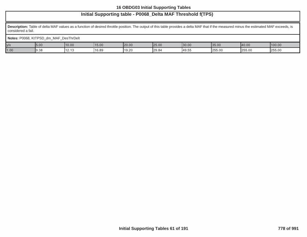
Initial Supporting table - P0068_Delta MAF Threshold f(TPS)OBD GROUP:OBD GROUP: TESTTEST GROUP: G ---BIN4, FED---BIN4EMISSIONS STDS: Bin 4
Description: Table of delta MAF values as a function of desired throttle position. The output of this table provides a delta MAF that if the measured minus the estimated MAF exceeds, isconsidered a fail.
Notes: P0068, KtTPSD_dm_MAF_DesThrDelt
y/x 5.00 10.00 15.00 20.00 25.00 30.00 35.00 40.00 100.00
1.00 9.38 12.13 16.89 19.20 29.84 49.55 255.00 255.00 255.00
556
16 OBDG03 Initial Supporting Tables
Initial Supporting Tables 61 of 191 778 of 991

Initial Supporting table - P0068_Delta MAP Threshold f(TPS)OBD GROUP:OBD GROUP: G TESTTEST GROUP: GGMXT -BIN4, FED---BIN4EMISSIONS STDS: Bin 4
Description: Table of delta MAP values as a function of desired throttle position. The output of this table provides a delta MAP that if the measured minus the estimated MAP exceeds, isconsidered a fail.
Notes: P0068, KtTPSD_p_MAP_DesThrDelt
y/x 5.00 10.00 15.00 20.00 25.00 30.00 35.00 40.00 100.001.00 37.45 44.08 46.55 45.54 46.96 41.86 255.00 255.00 255.00
557
16 OBDG03 Initial Supporting Tables
Initial Supporting Tables 62 of 191 779 of 991

Initial Supporting table - P0068_Maximum MAF f(RPM)OBD GROUP:OBD GROUP: TESTTEST GROUP: G L---BIN4, FED---BIN4EMISSIONS STDS: Bin 4
Description: Table of maximum MAF values vs. engine speed. This is the maximum MAF the engine can see under all ambient conditions.
Notes: P0068, KtTPSD_dm_MaxMAF_VsRPM
y/x 600.00 1,400.00 2,200.00 3,000.00 3,800.00 4,600.00 5,400.00 6,200.00 7,000.001.00 17.90 39.19 63.43 80.91 112.92 138.31 168.70 174.20 176.70
558
16 OBDG03 Initial Supporting Tables
Initial Supporting Tables 63 of 191 780 of 991

Initial Supporting table - P0068_Maximum MAF f(Volts)OBD GROUP:OBD GROUP: G TESTTEST GROUP: G L---BIN4, FED---BIN4EMISSIONS STDS: Bin 4
Description: Table of maximum MAF values vs. system voltage. The output of the air meter is clamped to lower values as system voltage drops off.
Notes: P0068, KtTPSD_dm_MaxMAF_VsVoltage
y/x 6.00 7.00 8.00 9.00 10.00 11.00 12.00 13.00 14.001.00 6.50 25.00 65.00 140.00 260.00 300.00 300.70 300.70 300.70
559
16 OBDG03 Initial Supporting Tables
Initial Supporting Tables 64 of 191 781 of 991

Initial Supporting table - P0101, P0106, P010B, P0121, P012B, P0236, P1101: MAF1 Residual Weight Factor based on MAF EstOBD GROUP:OBD GROUP: GGMXOBD TESTTEST GROUP: GGMXT BIN4, FED---BIN4EMISSIONS STDS: Bin 4
Description: P0101_P0106_P010B_P0121_P012B_P0236_P1101 MAF1 Residual Weight Factor based on MAF Est
Notes:
y/x 0 15 30 45 60 75 90 105 120 135 150 165 180 195 210 230 2501 1 1 1 1 1 1 1 1 1 1 1 1 1 1 1 1 1
560
16 OBDG03 Initial Supporting Tables
Initial Supporting Tables 65 of 191 782 of 991

Initial Supporting table - P0101, P0106, P010B, P0121, P012B, P0236, P1101: MAF1 Residual Weight Factor based on RPMOBD GROUP:OBD GROUP: TESTTEST GROUP: G CAL---BIN4, FED---BIN4EMISSIONS STDS:4
Description: P0101_P0106_P010B_P0121_P012B_P0236_P1101 MAF1 Residual Weight Factor based on RPM
Notes:
y/x 0 400 800 1,200 1,600 2,000 2,400 2,800 3,200 3,600 4,000 4,400 4,800 5,200 5,600 6,000 6,200
1 1 1 1 1 1 1 1 1 1 1 1 1 1 1 1 1 1
561
16 OBDG03 Initial Supporting Tables
Initial Supporting Tables 66 of 191 783 of 991

Initial Supporting table - P0116_Fail if power up ECT exceeds IAT by these valuesOBD GROUP:OBD GROUP: TESTTEST GROUP: GGM L---BIN4, FED---BIN4EMISSIONS STDS: Bin 4
Description: KtECTD_T_HSC_FastFailTempDiff
Notes: X axis is IAT Temperature at Power up (° C), Z axis is the Fast Failure temp difference (° C)
y/x -40 -28 -16 -4 8 20 32 44 56 68 80 92 104 116 128 140 152
1 80 80 80 60 60 40 40 30 30 30 30 30 30 30 30 30 30
562
16 OBDG03 Initial Supporting Tables
Initial Supporting Tables 67 of 191 784 of 991

Initial Supporting table - P0128_Maximum Accumulated Energy for Start-up ECT conditions - AlternateOBD GROUP:OBD GROUP: TESTTEST GROUP: G --BIN4, FED---BIN4EMISSIONS STDS: Bin 4
Description: KtECTR_E_CTR_WrmUpEnrgyLimTest1
Notes: Z axis is the cooling system energy failure threshold (kJ), X axis is ECT Temperature at Power up (° C), (Deluxe version)
y/x -20 -5 10 30 45 60 75
1 8,600 7,400 6,200 4,600 3,400 2,200 2,200
563
16 OBDG03 Initial Supporting Tables
Initial Supporting Tables 68 of 191 785 of 991

Initial Supporting table - P0128_Maximum Accumulated Energy for Start-up ECT conditions - PrimaryOBD GROUP:OBD GROUP: TESTTEST GROUP: GGM ---BIN4, FED---BIN4EMISSIONS STDS: Bin 4
Description: KtECTR_E_CTR_WrmUpEnrgyLimTest0
Notes: Z axis is the cooling system energy failure threshold (kJ), X axis is ECT Temperature at Power up (° C) , (Deluxe version)
y/x -20 -5 10 30 45 60 75
1 8,600 8,600 7,400 5,800 4,600 3,400 2,200
564
16 OBDG03 Initial Supporting Tables
Initial Supporting Tables 69 of 191 786 of 991

Initial Supporting table - P0606_Last Seed Timeout f(Loop Time)OBD GROUP:OBD GROUP: TESTTEST GROUP: GG L---BIN4, FED---BIN4EMISSIONS STDS: Bin 4
Description: The max time for the Last Seed Timeout as a function of operating loop time sequence.
Notes: P0606, KaPISD_t_LastSeedTimeout[x]
y/x CePISR_e_6p25msSeq CePISR_e_12p5msSeq CePISR_e_25msSeq CePISR_e_LORES_C1 0.175 0.175 0.175 409.594
565
16 OBDG03 Initial Supporting Tables
Initial Supporting Tables 70 of 191 787 of 991

Initial Supporting table - P0606_PSW Sequence Fail f(Loop Time)OBD GROUP:OBD GROUP: TESTTEST GROUP: G BIN4, FED---BIN4EMISSIONS STDS: Bin 4
Description: Fail threshold for PSW per operating loop.
Notes: P0606, KaPISD_Cnt_SequenceFail[x]
y/x CePISR_e_6p25msSeq CePISR_e_12p5msSeq CePISR_e_25msSeq CePISR_e_LORES_C1 3 3 3 3
566
16 OBDG03 Initial Supporting Tables
Initial Supporting Tables 71 of 191 788 of 991

Initial Supporting table - P0606_PSW Sequence Sample f(Loop Time)OBD GROUP:OBD GROUP: TESTTEST GROUP: G --BIN4, FED---BIN4EMISSIONS STDS: Bin 4
Description: Sample threshold for PSW per operating loop.
Notes: P0606, KaPISD_Cnt_SequenceSmpl[x]
y/x CePISR_e_6p25msSeq CePISR_e_12p5msSeq CePISR_e_25msSeq CePISR_e_LORES_C1 4 4 4 4
567
16 OBDG03 Initial Supporting Tables
Initial Supporting Tables 72 of 191 789 of 991

Initial Supporting table - P1682_PT Relay Pull-in Run/Crank Voltage f(IAT)OBD GROUP:OBD GROUP: TESTTEST GROUP: G 4, FED---BIN4EMISSIONS STDS: Bin 4
Description: The Run/Crank voltages required to pull in the PT relay as a function of induction air temperature.
Notes: P1682, KtEROR_U_PT_RelayPullInEnbl
y/x 23.00 85.00 95.00 105.00 125.00
1.00 7.00 8.70 9.00 9.20 10.00
568
16 OBDG03 Initial Supporting Tables
Initial Supporting Tables 73 of 191 790 of 991

Initial Supporting table - P16F3_Delta MAP Threshold f(Desired Engine Torque)OBD GROUP:OBD GROUP: TESTTEST GROUP: G E--BIN4, FED---BIN4EMISSIONS STDS: Bin 4
Description: Engine Sync based and Time based delta pressure threshold above which Torque Security error is reported.
Notes: P16F3, KtMAPI_p_ES_TB_MAP_DeltaThresh
y/x 0.00 50.00 100.00 150.00 200.00 300.00
1.00 37.45 37.45 37.45 37.45 37.45 37.45
569
16 OBDG03 Initial Supporting Tables
Initial Supporting Tables 74 of 191 791 of 991

Initial Supporting table - P16F3_Delta Spark Threshold f(RPM,APC)OBD GROUP:OBD GROUP: TESTTEST GROUP: G --BIN4, FED---BIN4EMISSIONS STDS: Bin 4
Description: Threshold for determining when the difference between commanded spark and applied spark exceeds the torque security requirement. It is a function of engine rpm and APC.
Notes: P16F3, KtSPRK_phi_DeltTorqueScrtyAdv
y/x 500.00 980.74 1,461.48 1,942.23 2,422.97 2,903.71 3,384.45 3,865.20 4,345.94 4,826.68 5,307.42 5,788.16 6,268.91 6,749.65 7,230.39 7,711.13 8,191.8880.00 125.00 52.69 44.70 42.08 45.31 51.31 55.84 57.95 55.66 51.81 51.00 48.47 43.27 31.38 29.86 29.86 29.86160.00 125.00 51.22 49.03 48.13 50.14 54.17 57.50 59.66 57.48 53.75 52.41 48.92 42.13 30.25 28.80 28.80 28.80240.00 125.00 49.41 49.95 50.94 53.69 56.53 59.06 61.09 59.09 55.61 53.17 48.66 40.92 29.20 27.81 27.81 27.81320.00 125.00 47.73 50.92 54.11 57.78 59.14 60.70 62.59 60.30 56.44 53.56 48.42 39.80 27.97 26.61 26.61 26.61400.00 125.00 45.98 49.36 52.08 59.36 60.86 62.45 64.17 61.08 56.23 53.55 48.22 38.75 26.63 25.25 25.25 25.25480.00 125.00 43.23 43.83 45.75 53.25 56.95 59.55 60.36 56.48 51.13 51.64 47.97 37.77 25.42 24.05 24.05 24.05560.00 125.00 39.16 38.47 40.80 48.22 52.20 54.77 55.09 51.53 46.75 47.41 44.53 36.16 24.31 22.94 22.94 22.94640.00 125.00 37.59 36.66 39.08 46.44 50.48 53.05 53.20 49.75 45.19 45.86 43.20 35.38 23.86 22.52 22.52 22.52720.00 125.00 37.59 36.66 39.08 46.44 50.48 53.05 53.20 49.75 45.19 45.86 43.20 35.38 23.86 22.52 22.52 22.52800.00 125.00 37.59 36.66 39.08 46.44 50.48 53.05 53.20 49.75 45.19 45.86 43.20 35.38 23.86 22.52 22.52 22.52880.00 125.00 37.59 36.66 39.08 46.44 50.48 53.05 53.20 49.75 45.19 45.86 43.20 35.38 23.86 22.52 22.52 22.52960.00 125.00 37.59 36.66 39.08 46.44 50.48 53.05 53.20 49.75 45.19 45.86 43.20 35.38 23.86 22.52 22.52 22.521,040.00 125.00 37.59 36.66 39.08 46.44 50.48 53.05 53.20 49.75 45.19 45.86 43.20 35.38 23.86 22.52 22.52 22.521,120.00 125.00 37.59 36.66 39.08 46.44 50.48 53.05 53.20 49.75 45.19 45.86 43.20 35.38 23.86 22.52 22.52 22.521,200.00 125.00 37.59 36.66 39.08 46.44 50.48 53.05 53.20 49.75 45.19 45.86 43.20 35.38 23.86 22.52 22.52 22.521,280.00 125.00 37.59 36.66 39.08 46.44 50.48 53.05 53.20 49.75 45.19 45.86 43.20 35.38 23.86 22.52 22.52 22.521,360.00 125.00 37.59 36.66 39.08 46.44 50.48 53.05 53.20 49.75 45.19 45.86 43.20 35.38 23.86 22.52 22.52 22.52
570
16 OBDG03 Initial Supporting Tables
Initial Supporting Tables 75 of 191 792 of 991
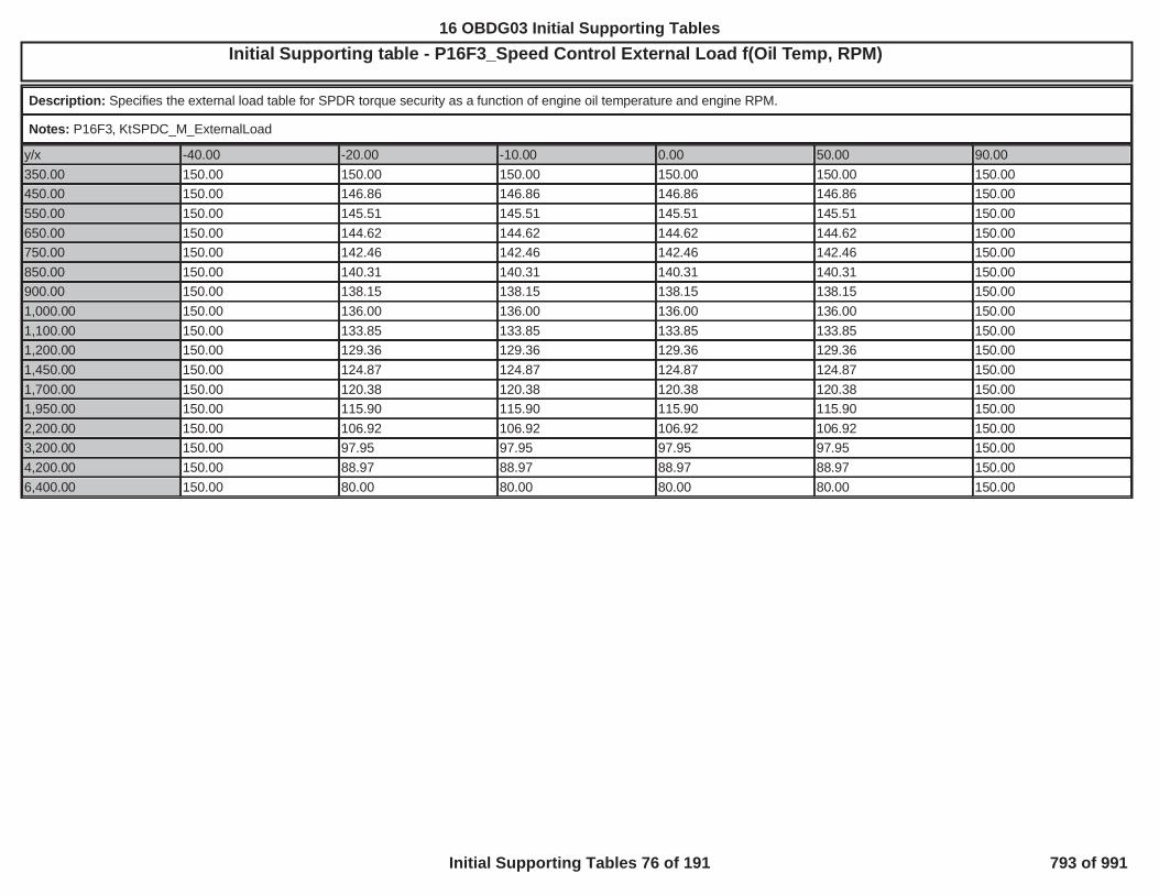
Initial Supporting table - P16F3_Speed Control External Load f(Oil Temp, RPM)OBD GROUP:OBD GROUP: TESTTEST GROUP: G -BIN4, FED---BIN4EMISSIONS STDS: Bin 4
Description: Specifies the external load table for SPDR torque security as a function of engine oil temperature and engine RPM.
Notes: P16F3, KtSPDC_M_ExternalLoad
y/x -40.00 -20.00 -10.00 0.00 50.00 90.00350.00 150.00 150.00 150.00 150.00 150.00 150.00450.00 150.00 146.86 146.86 146.86 146.86 150.00550.00 150.00 145.51 145.51 145.51 145.51 150.00650.00 150.00 144.62 144.62 144.62 144.62 150.00750.00 150.00 142.46 142.46 142.46 142.46 150.00850.00 150.00 140.31 140.31 140.31 140.31 150.00900.00 150.00 138.15 138.15 138.15 138.15 150.001,000.00 150.00 136.00 136.00 136.00 136.00 150.001,100.00 150.00 133.85 133.85 133.85 133.85 150.001,200.00 150.00 129.36 129.36 129.36 129.36 150.001,450.00 150.00 124.87 124.87 124.87 124.87 150.001,700.00 150.00 120.38 120.38 120.38 120.38 150.001,950.00 150.00 115.90 115.90 115.90 115.90 150.002,200.00 150.00 106.92 106.92 106.92 106.92 150.003,200.00 150.00 97.95 97.95 97.95 97.95 150.004,200.00 150.00 88.97 88.97 88.97 88.97 150.006,400.00 150.00 80.00 80.00 80.00 80.00 150.00
571
16 OBDG03 Initial Supporting Tables
Initial Supporting Tables 76 of 191 793 of 991

Initial Supporting table - 1st_FireAftrMisfr_AcelOBD GROUP:OBD GROUP: G TESTTEST GROUP: GG ---BIN4, FED---BIN4EMISSIONS STDS: Bin 4
Description: Multiplier for establishing the expected acceleration of the cylinder after the misfire
Notes: Used for P0300 - P0308, Cal Name: KtMSFD_K_dt_CylAftMsfr
y/x 600 800 1,000 1,200 1,600 2,000 2,400 2,800 3,000 3,500 4,000 4,500 5,000 5,500 6,000 6,500 7,000
2 0.60 0.70 0.80 0.70 0.70 0.80 0.80 0.80 0.80 0.80 0.80 0.80 0.80 0.80 0.80 0.80 0.80
8 0.60 0.70 0.80 0.70 0.70 0.80 0.80 0.80 0.80 0.80 0.80 0.80 0.80 0.80 0.80 0.80 0.80
12 0.70 0.70 0.70 0.70 0.70 0.70 0.70 0.70 0.70 0.70 0.70 0.70 0.70 0.70 0.70 0.70 0.70
16 0.50 0.60 0.60 0.60 0.70 0.70 0.70 0.70 0.70 0.70 0.70 0.70 0.60 0.50 0.60 0.50 0.60
20 0.30 0.30 0.30 0.50 0.75 0.80 0.80 0.80 0.80 0.80 0.80 0.80 0.60 0.50 0.50 0.50 0.50
24 0.00 0.00 0.00 0.30 0.50 0.65 0.70 0.70 0.50 0.65 0.70 0.50 0.50 0.50 0.50 0.50 0.50
30 0.00 0.00 0.00 0.00 0.00 0.30 0.40 0.40 0.40 0.40 0.40 0.40 0.40 0.40 0.40 0.50 0.50
40 0.00 0.00 0.00 0.00 0.00 0.00 0.20 0.20 0.20 0.20 0.20 0.20 0.25 0.30 0.30 0.50 0.50
60 0.00 0.00 0.00 0.00 0.00 0.00 0.00 0.00 0.00 0.00 0.00 0.00 0.25 0.30 0.30 0.50 0.50
572
16 OBDG03 Initial Supporting Tables
Initial Supporting Tables 77 of 191 794 of 991

Initial Supporting table - 1st_FireAftrMisfr_JerkOBD GROUP:OBD GROUP: GGMXOB TESTTEST GROUP: G 4
Description: Multiplier for establishing the expected Jerk of the cylinder after the misfire
Notes: Used for P0300 - P0308, Cal Name: KtMSFD_K_ddt_CylAftMsfr
y/x 600 800 1,000 1,200 1,600 2,000 2,400 2,800 3,000 3,500 4,000 4,500 5,000 5,500 6,000 6,500 7,0002 -0.70 -0.60 -0.60 -0.60 -0.60 -0.60 -0.60 -0.60 -0.60 -0.60 -0.60 -0.60 -0.60 -0.60 -0.60 -0.60 -0.608 -0.60 -0.60 -0.60 -0.60 -0.80 -0.70 -0.70 -0.70 -0.60 -0.60 -0.60 -0.60 -0.60 -0.60 -0.60 -0.60 -0.6012 -0.50 -0.60 -0.60 -0.60 -0.90 -0.90 -0.90 -0.90 -0.90 -0.90 -0.80 -0.70 -0.70 -0.60 -0.60 -0.60 -0.6016 -0.70 -0.80 -0.80 -0.80 -0.85 -0.85 -0.90 -0.90 -0.90 -0.90 -0.90 -0.90 -0.85 -0.75 -0.70 -0.70 -0.7020 -0.80 -0.80 -0.90 -0.80 -0.75 -0.90 -0.90 -0.90 -0.90 -0.90 -0.90 -1.00 -1.00 -1.00 -0.99 -0.80 -0.8024 -1.00 -1.00 -0.90 -0.85 -0.75 -0.90 -0.90 -0.90 -0.90 -0.90 -1.00 -1.00 -1.00 -1.00 -0.90 -0.90 -0.9030 -1.00 -1.00 -0.90 -0.85 -0.70 -0.90 -0.90 -0.85 -0.90 -1.00 -1.00 -1.00 -1.00 -1.00 -0.90 -1.00 -1.0040 -1.00 -1.00 -1.00 -1.00 -1.00 -1.00 -1.00 -0.85 -0.90 -1.00 -1.00 -1.00 -1.00 -1.00 -1.00 -1.00 -1.0060 -1.00 -1.00 -1.00 -1.00 -1.00 -1.00 -1.00 -1.00 -1.00 -1.00 -1.00 -1.00 -1.00 -1.00 -1.00 -1.00 -1.00
573
16 OBDG03 Initial Supporting Tables
Initial Supporting Tables 78 of 191 795 of 991

Initial Supporting table - Abnormal Cyl ModeOBD GROUP:OBD GROUP: TESTTEST GROUP: G L---BIN4, FED---BIN4EMISSIONS STDS: Bin 4
Description: Number of consecutive number of decelerating cylinders after the misfire that would be considered abnormal. (Cylinder Mode Equation)
Notes: Used for P0300-P0308. Cal Name: KaMSFD_Cnt_CylAbnormal
y/x 0 1 2 3 4 5 6 7 8
1 3.00 3.00 3.00 3.00 3.00 3.00 3.00 3.00 3.00
574
16 OBDG03 Initial Supporting Tables
Initial Supporting Tables 79 of 191 796 of 991

Initial Supporting table - Abnormal Rev ModeOBD GROUP:OBD GROUP: GG TESTTEST GROUP: G L---BIN4, FED---BIN4EMISSIONS STDS: Bin 4
Description: Abnormal Rev Mode Number of consecutive number of decelerating cylinders after the misfire that would be considered abnormal. (Rev Mode Equation)
Notes: Used for P0300-P0308. Cal Name: KaMSFD_Cnt_RevAbnormal
y/x 0 1 2 3 4 5 6 7 8
1 2.00 2.00 2.00 2.00 2.00 2.00 2.00 2.00 2.00
575
16 OBDG03 Initial Supporting Tables
Initial Supporting Tables 80 of 191 797 of 991

Initial Supporting table - Abnormal SCD ModeOBD GROUP:OBD GROUP: GGM TESTTEST GROUP: GG ---BIN4, FED---BIN4EMISSIONS STDS: Bin 4
Description: Number of consecutive number of decelerating cylinders after the misfire that would be considered abnormal. (SCD Mode Equation)
Notes: Used for P0300-P0308. Cal Name: KaMSFD_Cnt_SCD_CylAbnormal
y/x 0 1 2 3 4 5 6 7 8
1 2.00 2.00 2.00 2.00 2.00 2.00 2.00 2.00 2.00
576
16 OBDG03 Initial Supporting Tables
Initial Supporting Tables 81 of 191 798 of 991

Initial Supporting table - Bank_SCD_DecelOBD GROUP:OBD GROUP: TESTTEST GROUP: G -BIN4, FED---BIN4EMISSIONS STDS: Bin 4
Description: Mulitplier to SCD decel to account for different pattern of Paired cylinder misfire. Multipliers are a function of engine rpm and % engine Load.
Notes: Used for P0300 - P0308, Cal Name: KtMSFD_K_dt_MEDRES_Bank
y/x 400 550 700 800 900 1,000 1,200 1,400 1,6002 1.00 1.00 1.00 1.00 1.00 1.00 1.00 1.00 1.008 1.00 1.00 1.00 1.00 1.00 1.00 1.00 1.00 1.0012 1.00 1.00 1.00 1.00 1.00 1.00 1.00 1.00 1.0016 1.00 1.00 1.00 1.00 1.00 1.00 1.00 1.00 1.0020 1.00 1.00 1.00 1.00 1.00 1.00 1.00 1.00 1.0024 1.00 1.00 1.00 1.00 1.00 1.00 1.00 1.00 1.0030 1.00 1.00 1.00 1.00 1.00 1.00 1.00 1.00 1.0040 1.00 1.00 1.00 1.00 1.00 1.00 1.00 1.00 1.0060 1.00 1.00 1.00 1.00 1.00 1.00 1.00 1.00 1.00
577
16 OBDG03 Initial Supporting Tables
Initial Supporting Tables 82 of 191 799 of 991

Initial Supporting table - Bank_SCD_JerkOBD GROUP:OBD GROUP: TESTTEST GROUP: G -BIN4, FED---BIN4EMISSIONS STDS: Bin 4
Description: Mulitplier to Medres SCD jerk to account for different pattern of Paired cylinder misfire. Multipliers are a function of engine rpm and % engine Load.
Notes: Used for P0300 - P0308, Cal Name: KtMSFD_K_ddt_MEDRES_Bank
y/x 400 550 700 800 900 1,000 1,200 1,400 1,6002 1.00 1.00 1.00 1.00 1.00 1.00 1.00 1.00 1.008 1.00 1.00 1.00 1.00 1.00 1.00 1.00 1.00 1.0012 1.00 1.00 1.00 1.00 1.00 1.00 1.00 1.00 1.0016 1.00 1.00 1.00 1.00 1.00 1.00 1.00 1.00 1.0020 1.00 1.00 1.00 1.00 1.00 1.00 1.00 1.00 1.0024 1.00 1.00 1.00 1.00 1.00 1.00 1.00 1.00 1.0030 1.00 1.00 1.00 1.00 1.00 1.00 1.00 1.00 1.0040 1.00 1.00 1.00 1.00 1.00 1.00 1.00 1.00 1.0060 1.00 1.00 1.00 1.00 1.00 1.00 1.00 1.00 1.00
578
16 OBDG03 Initial Supporting Tables
Initial Supporting Tables 83 of 191 800 of 991

Initial Supporting table - BankCylModeDecelOBD GROUP:OBD GROUP: G TESTTEST GROUP: G EMIBIN4, FED---BIN4EMISSIONS STDS: Bin 4
Description: Mulitplier to Lores Decel to account for different pattern of Paired cylinder misfire. Multipliers are a function of engine rpm and % engine Load.
Notes: Used for P0300 - P0308, Cal Name: KtMSFD_K_dt_LORES_Bank
y/x 400 600 800 1,000 1,200 1,600 2,000 2,400 2,800 3,000 3,500 4,000 4,500 5,000 5,500 6,000 7,0002 5.00 5.00 15.00 15.00 15.00 15.00 15.00 15.00 15.00 15.00 15.00 15.00 15.00 15.00 15.00 15.00 15.008 4.00 4.50 15.00 15.00 15.00 15.00 15.00 15.00 15.00 15.00 15.00 15.00 15.00 15.00 15.00 15.00 15.0012 3.00 3.50 12.00 15.00 15.00 15.00 15.00 15.00 15.00 15.00 15.00 15.00 15.00 15.00 15.00 15.00 15.0016 2.80 3.00 11.00 15.00 15.00 15.00 15.00 15.00 15.00 15.00 15.00 15.00 15.00 15.00 15.00 15.00 15.0020 2.50 2.40 9.00 13.00 15.00 15.00 15.00 15.00 15.00 15.00 15.00 15.00 15.00 15.00 15.00 15.00 15.0024 2.00 2.00 7.00 10.00 15.00 15.00 15.00 15.00 15.00 15.00 15.00 15.00 15.00 15.00 15.00 15.00 15.0030 1.76 1.76 5.00 9.00 12.00 15.00 15.00 15.00 15.00 15.00 15.00 15.00 15.00 15.00 15.00 15.00 15.0040 1.67 1.67 3.33 6.00 8.00 15.00 15.00 15.00 15.00 15.00 15.00 15.00 15.00 15.00 15.00 15.00 15.0060 1.50 1.50 2.50 3.75 5.00 13.00 15.00 15.00 15.00 15.00 15.00 15.00 15.00 15.00 15.00 15.00 15.00
579
16 OBDG03 Initial Supporting Tables
Initial Supporting Tables 84 of 191 801 of 991

Initial Supporting table - BankCylModeJerkOBD GROUP:OBD GROUP: TESTTEST GROUP: G --BIN4, FED---BIN4EMISSIONS STDS: Bin 4
Description: Mulitplier to Lores Jerk to account for different pattern of Paired cylinder misfire. Multipliers are a function of engine rpm and % engine Load.
Notes: Used for P0300 - P0308, Cal Name: KtMSFD_K_ddt_LORES_Bank
y/x 400 600 800 1,000 1,200 1,600 2,000 2,400 2,800 3,000 3,500 4,000 4,500 5,000 5,500 6,000 7,000
2 3.75 6.00 15.00 15.00 15.00 15.00 15.00 15.00 15.00 15.00 15.00 15.00 15.00 15.00 15.00 15.00 15.00
8 3.00 3.00 10.00 15.00 15.00 15.00 15.00 15.00 15.00 15.00 15.00 15.00 15.00 15.00 15.00 15.00 15.00
12 2.00 2.00 8.00 12.00 15.00 15.00 15.00 15.00 15.00 15.00 15.00 15.00 15.00 15.00 15.00 15.00 15.00
16 1.50 1.50 5.00 8.50 15.00 15.00 15.00 15.00 15.00 15.00 15.00 15.00 15.00 15.00 15.00 15.00 15.00
20 1.50 1.50 3.00 7.00 14.00 15.00 15.00 15.00 15.00 15.00 15.00 15.00 15.00 15.00 15.00 15.00 15.00
24 1.50 1.50 2.00 6.00 10.00 15.00 15.00 15.00 15.00 15.00 15.00 15.00 15.00 15.00 15.00 15.00 15.00
30 1.50 1.50 1.50 4.00 8.00 15.00 15.00 15.00 15.00 15.00 15.00 15.00 15.00 15.00 15.00 15.00 15.00
40 1.50 1.50 1.50 3.00 5.00 15.00 15.00 15.00 15.00 15.00 15.00 15.00 15.00 15.00 15.00 15.00 15.00
60 1.50 1.50 1.50 2.00 3.00 7.00 13.00 15.00 15.00 15.00 15.00 15.00 15.00 15.00 15.00 15.00 15.00
580
16 OBDG03 Initial Supporting Tables
Initial Supporting Tables 85 of 191 802 of 991

Initial Supporting table - CalculatedPerfMaxEc1OBD GROUP:OBD GROUP: TESTTEST GROUP: G L---BIN4, FED---BIN4EMISSIONS STDS: Bin 4
Description:
Notes:
y/x 1 2 3 4 5 6 7 8 9 10 11 12 13 14 15 16 171 26.0 26.0 26.0 26.0 26.0 26.0 26.0 26.0 26.0 26.0 26.0 26.0 26.0 26.0 26.0 26.0 26.02 26.0 26.0 26.0 26.0 26.0 26.0 26.0 26.0 26.0 26.0 26.0 26.0 26.0 26.0 26.0 26.0 26.03 26.0 26.0 26.0 26.0 26.0 26.0 26.0 26.0 26.0 26.0 26.0 26.0 26.0 26.0 26.0 26.0 26.04 26.0 26.0 26.0 26.0 26.0 26.0 26.0 26.0 26.0 26.0 26.0 26.0 26.0 26.0 26.0 26.0 26.05 26.0 26.0 26.0 26.0 26.0 26.0 26.0 26.0 26.0 26.0 26.0 26.0 26.0 26.0 26.0 26.0 26.06 26.0 26.0 26.0 26.0 26.0 26.0 26.0 26.0 26.0 26.0 26.0 26.0 26.0 26.0 26.0 26.0 26.07 26.0 26.0 26.0 26.0 26.0 26.0 26.0 26.0 26.0 26.0 26.0 26.0 26.0 26.0 26.0 26.0 26.08 26.0 26.0 26.0 26.0 26.0 26.0 26.0 26.0 26.0 26.0 26.0 26.0 26.0 26.0 26.0 26.0 26.09 26.0 26.0 26.0 26.0 26.0 26.0 26.0 26.0 26.0 26.0 26.0 26.0 26.0 26.0 26.0 26.0 26.010 26.0 26.0 26.0 26.0 26.0 26.0 26.0 26.0 26.0 26.0 26.0 26.0 26.0 26.0 26.0 26.0 26.011 26.0 26.0 26.0 26.0 26.0 26.0 26.0 26.0 26.0 26.0 26.0 26.0 26.0 26.0 26.0 26.0 26.012 26.0 26.0 26.0 26.0 26.0 26.0 26.0 26.0 26.0 26.0 26.0 26.0 26.0 26.0 26.0 26.0 26.013 26.0 26.0 26.0 26.0 26.0 26.0 26.0 26.0 26.0 26.0 26.0 26.0 26.0 26.0 26.0 26.0 26.014 26.0 26.0 26.0 26.0 26.0 26.0 26.0 26.0 26.0 26.0 26.0 26.0 26.0 26.0 26.0 26.0 26.015 26.0 26.0 26.0 26.0 26.0 26.0 26.0 26.0 26.0 26.0 26.0 26.0 26.0 26.0 26.0 26.0 26.016 26.0 26.0 26.0 26.0 26.0 26.0 26.0 26.0 26.0 26.0 26.0 26.0 26.0 26.0 26.0 26.0 26.017 26.0 26.0 26.0 26.0 26.0 26.0 26.0 26.0 26.0 26.0 26.0 26.0 26.0 26.0 26.0 26.0 26.0
581
16 OBDG03 Initial Supporting Tables
Initial Supporting Tables 86 of 191 803 of 991

Initial Supporting table - CalculatedPerfMaxIc1OBD GROUP:OBD GROUP: TESTTEST GROUP: G IN4, FED---BIN4EMISSIONS STDS: Bin 4
Description:
Notes:
y/x 1 2 3 4 5 6 7 8 9 10 11 12 13 14 15 16 171 26.0 26.0 26.0 26.0 26.0 26.0 26.0 26.0 26.0 26.0 26.0 26.0 26.0 26.0 26.0 26.0 26.02 26.0 26.0 26.0 26.0 26.0 26.0 26.0 26.0 26.0 26.0 26.0 26.0 26.0 26.0 26.0 26.0 26.03 26.0 26.0 26.0 26.0 26.0 26.0 26.0 26.0 26.0 26.0 26.0 26.0 26.0 26.0 26.0 26.0 26.04 26.0 26.0 26.0 26.0 26.0 26.0 26.0 26.0 26.0 26.0 26.0 26.0 26.0 26.0 26.0 26.0 26.05 26.0 26.0 26.0 26.0 26.0 26.0 26.0 26.0 26.0 26.0 26.0 26.0 26.0 26.0 26.0 26.0 26.06 26.0 26.0 26.0 26.0 26.0 26.0 26.0 26.0 26.0 26.0 26.0 26.0 26.0 26.0 26.0 26.0 26.07 26.0 26.0 26.0 26.0 26.0 26.0 26.0 26.0 26.0 26.0 26.0 26.0 26.0 26.0 26.0 26.0 26.08 26.0 26.0 26.0 26.0 26.0 26.0 26.0 26.0 26.0 26.0 26.0 26.0 26.0 26.0 26.0 26.0 26.09 26.0 26.0 26.0 26.0 26.0 26.0 26.0 26.0 26.0 26.0 26.0 26.0 26.0 26.0 26.0 26.0 26.010 26.0 26.0 26.0 26.0 26.0 26.0 26.0 26.0 26.0 26.0 26.0 26.0 26.0 26.0 26.0 26.0 26.011 26.0 26.0 26.0 26.0 26.0 26.0 26.0 26.0 26.0 26.0 26.0 26.0 26.0 26.0 26.0 26.0 26.012 26.0 26.0 26.0 26.0 26.0 26.0 26.0 26.0 26.0 26.0 26.0 26.0 26.0 26.0 26.0 26.0 26.013 26.0 26.0 26.0 26.0 26.0 26.0 26.0 26.0 26.0 26.0 26.0 26.0 26.0 26.0 26.0 26.0 26.014 26.0 26.0 26.0 26.0 26.0 26.0 26.0 26.0 26.0 26.0 26.0 26.0 26.0 26.0 26.0 26.0 26.015 26.0 26.0 26.0 26.0 26.0 26.0 26.0 26.0 26.0 26.0 26.0 26.0 26.0 26.0 26.0 26.0 26.016 26.0 26.0 26.0 26.0 26.0 26.0 26.0 26.0 26.0 26.0 26.0 26.0 26.0 26.0 26.0 26.0 26.017 26.0 26.0 26.0 26.0 26.0 26.0 26.0 26.0 26.0 26.0 26.0 26.0 26.0 26.0 26.0 26.0 26.0
582
16 OBDG03 Initial Supporting Tables
Initial Supporting Tables 87 of 191 804 of 991

Initial Supporting table - Catalyst_Damage_Misfire_PercentageOBD GROUP:OBD GROUP: TESTTEST GROUP: G L---BIN4, FED---BIN4EMISSIONS STDS: Bin 4
Description: Catalyst Damaging Misfire Percentage" Table whenever secondary conditions are met.
Notes: Used for P0300-P0308. Cal Name: KtMSFD_Pct_CatalystMisfire
y/x 0 1,000 2,000 3,000 4,000 5,000 6,000 7,0000 22.5 22.5 22.5 20.0 16.7 14.3 9.0 5.010 22.5 22.5 20.0 16.7 11.1 10.0 6.3 4.720 22.5 20.0 16.7 12.5 9.0 7.1 5.0 4.730 20.0 16.7 12.5 10.0 6.3 5.0 4.7 4.740 16.7 12.5 7.7 6.3 5.0 4.7 4.7 4.750 12.5 10.0 6.3 5.0 4.7 4.7 4.7 4.760 10.0 6.3 5.0 4.7 4.7 4.7 4.7 4.770 6.3 5.0 4.7 4.7 4.7 4.7 4.7 4.780 5.0 4.7 4.7 4.7 4.7 4.7 4.7 4.790 4.7 4.7 4.7 4.7 4.7 4.7 4.7 4.7100 4.7 4.7 4.7 4.7 4.7 4.7 4.7 4.7
583
16 OBDG03 Initial Supporting Tables
Initial Supporting Tables 88 of 191 805 of 991

Initial Supporting table - ClyAfterAFM_DecelOBD GROUP:OBD GROUP: TESTTEST GROUP: G BIN4, FED---BIN4EMISSIONS STDS: Bin 4
Description: Mulitplier to Lores decel to account for different pattern of misfire after a deactivated cylider. Similar to the second cylinder of consecutive cylinder misfire. Multipliers are afunction of engine rpm and % engine Load.
Notes: Used for P0300 - P0308, Cal Name: KtMSFD_K_dt_LORES_PostDeac
y/x 800 1,000 1,200 1,600 2,000 2,400 2,600 3,000 3,5002 5.00 15.00 15.00 15.00 15.00 15.00 15.00 15.00 15.008 4.50 15.00 15.00 15.00 15.00 15.00 15.00 15.00 15.0012 3.50 15.00 15.00 15.00 15.00 15.00 15.00 15.00 15.0016 3.00 11.00 15.00 15.00 15.00 15.00 15.00 15.00 15.0020 2.50 15.00 15.00 15.00 15.00 15.00 15.00 15.00 15.0024 2.00 15.00 15.00 15.00 15.00 15.00 15.00 15.00 15.0030 1.88 13.00 15.00 15.00 15.00 15.00 15.00 15.00 15.0040 1.76 9.00 15.00 15.00 15.00 15.00 15.00 15.00 15.0060 1.50 4.00 6.50 15.00 15.00 15.00 15.00 15.00 15.00
584
16 OBDG03 Initial Supporting Tables
Initial Supporting Tables 89 of 191 806 of 991

Initial Supporting table - ClyBeforeAFM_JerkOBD GROUP:OBD GROUP: TESTTEST GROUP: GGMXT --BIN4, FED---BIN4EMISSIONS STDS: Bin 4
Description: Mulitplier to Lores decel to account for different pattern of misfire before a deactivated cylider, but after an active cylinder that follows an deactive cylinder on engine thatsupports cylinder deactivation in non even fire patterns.. Multipliers are a function of engine rpm and % engine Load.
Notes: KtMSFD_K_ddt_LORES_PreDeac KtMSFD_K_ddt_LORES_PreDeac
y/x 800 1,000 1,200 1,600 2,000 2,400 2,600 3,000 3,500
2 3.75 15.00 15.00 15.00 15.00 15.00 15.00 15.00 15.00
8 3.00 15.00 15.00 15.00 15.00 15.00 15.00 15.00 15.00
12 2.00 15.00 10.00 15.00 15.00 15.00 15.00 15.00 15.00
16 1.50 8.00 15.00 15.00 15.00 15.00 15.00 15.00 15.00
20 1.50 7.50 15.00 15.00 15.00 15.00 15.00 15.00 15.00
24 1.50 6.25 11.00 15.00 15.00 15.00 15.00 15.00 15.00
30 1.50 4.25 8.00 15.00 15.00 15.00 15.00 15.00 15.00
40 1.50 3.00 4.50 15.00 15.00 15.00 15.00 15.00 15.00
60 1.50 2.00 3.00 8.00 15.00 15.00 15.00 15.00 15.00
585
16 OBDG03 Initial Supporting Tables
Initial Supporting Tables 90 of 191 807 of 991

Initial Supporting table - ConsecCylModDecelOBD GROUP:OBD GROUP: TESTTEST GROUP: GGM L---BIN4, FED---BIN4EMISSIONS STDS: Bin 4
Description: Mulitplier to Lores decel to account for different pattern of the second cylinder of consecutive misfire. Multipliers are a function of engine rpm and % engine Load.
Notes: Used for P0300 - P0308, Cal Name: KtMSFD_K_dt_LORES_Consec
y/x 400 600 800 1,000 1,200 1,600 2,000 2,400 2,800 3,000 3,500 4,000 4,500 5,000 5,500 6,000 7,0002 2.00 2.00 2.00 2.00 2.00 2.00 2.00 2.00 2.00 2.00 2.00 2.00 2.00 2.00 2.25 2.50 2.508 1.50 1.50 1.45 1.25 1.10 1.10 1.25 1.50 1.35 1.25 1.25 1.25 1.25 1.25 1.50 1.80 2.0012 1.50 1.50 1.35 1.25 1.10 1.10 1.15 1.20 1.15 1.20 1.25 1.30 1.30 1.20 1.30 1.40 1.5016 1.40 1.40 1.25 1.35 1.20 1.20 1.15 1.00 1.20 1.25 1.30 1.35 1.40 1.35 1.30 1.40 1.5020 1.30 1.30 1.20 1.10 1.10 1.10 1.10 1.00 0.95 0.90 0.90 0.85 0.80 0.90 1.27 1.50 1.5024 1.20 1.20 1.10 1.10 1.00 1.00 1.00 1.00 1.00 1.00 0.90 0.70 0.75 0.80 1.00 1.30 1.3030 1.10 1.10 1.10 1.10 1.00 1.00 0.90 0.80 0.90 1.00 0.90 0.70 0.75 0.75 0.90 1.00 1.0040 1.10 1.10 1.10 1.10 1.00 1.00 0.95 0.85 0.95 1.00 1.00 0.90 0.85 0.85 1.00 1.00 1.0060 1.10 1.10 1.10 1.10 1.00 1.00 1.00 1.00 1.00 1.00 1.05 1.10 1.10 1.10 1.10 1.10 1.10
586
16 OBDG03 Initial Supporting Tables
Initial Supporting Tables 91 of 191 808 of 991

Initial Supporting table - ConsecCylModeJerkOBD GROUP:OBD GROUP: TESTTEST GROUP: G ---BIN4, FED---BIN4EMISSIONS STDS: Bin 4
Description: Mulitplier to Lores Jerk to account for different pattern of the second cylinder of consecutive misfire. Multipliers are a function of engine rpm and % engine Load.
Notes: Used for P0300 - P0308, Cal Name: KtMSFD_K_ddt_LORES_Consec
y/x 400 600 800 1,000 1,200 1,600 2,000 2,400 2,800 3,000 3,500 4,000 4,500 5,000 5,500 6,000 7,000
2 1 1 1 1 1 1 1 1 1 1 1 1 1 1 1 1 1
8 0 0 0 0 0 0 0 0 0 0 0 0 0 0 0 0 0
12 0 0 0 0 0 0 0 0 0 0 0 0 0 0 0 0 0
16 0 0 0 0 0 0 0 0 0 0 0 0 0 0 0 0 0
20 0 0 0 0 0 0 -1 -1 0 0 0 0 0 0 0 0 0
24 0 0 0 0 0 0 0 -1 -1 -1 0 0 0 0 0 0 0
30 0 0 0 0 0 0 0 -1 -1 -1 0 0 0 0 0 0 0
40 0 0 0 0 0 0 0 -1 -1 -1 0 0 0 0 0 0 0
60 0 0 0 0 0 0 0 0 0 -1 0 0 0 0 0 0 0
587
16 OBDG03 Initial Supporting Tables
Initial Supporting Tables 92 of 191 809 of 991
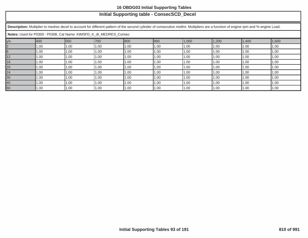
Initial Supporting table - ConsecSCD_DecelOBD GROUP:OBD GROUP: TESTTEST GROUP: G ---BIN4, FED---BIN4EMISSIONS STDS: Bin 4
Description: Mulitplier to medres decel to account for different pattern of the second cylinder of consecutive misfire. Multipliers are a function of engine rpm and % engine Load.
Notes: Used for P0300 - P0308, Cal Name: KtMSFD_K_dt_MEDRES_Consec
y/x 400 550 700 800 900 1,000 1,200 1,400 1,6002 1.00 1.00 1.00 1.00 1.00 1.00 1.00 1.00 1.008 1.00 1.00 1.00 1.00 1.00 1.00 1.00 1.00 1.0012 1.00 1.00 1.00 1.00 1.00 1.00 1.00 1.00 1.0016 1.00 1.00 1.00 1.00 1.00 1.00 1.00 1.00 1.0020 1.00 1.00 1.00 1.00 1.00 1.00 1.00 1.00 1.0024 1.00 1.00 1.00 1.00 1.00 1.00 1.00 1.00 1.0030 1.00 1.00 1.00 1.00 1.00 1.00 1.00 1.00 1.0040 1.00 1.00 1.00 1.00 1.00 1.00 1.00 1.00 1.0060 1.00 1.00 1.00 1.00 1.00 1.00 1.00 1.00 1.00
588
16 OBDG03 Initial Supporting Tables
Initial Supporting Tables 93 of 191 810 of 991

Initial Supporting table - ConsecSCD_JerkOBD GROUP:OBD GROUP: TESTTEST GROUP: GGMXT02.0100TEST GROUP: GGM L---BIN4, FED---BIN4EMISSIONS STDS: Bin 4
Description: Mulitplier to medres Jerk to account for different pattern of the second cylinder of consecutive misfire. Multipliers are a function of engine rpm and % engine Load.
Notes: Used for P0300 - P0308, Cal Name: KtMSFD_K_ddt_MEDRES_Consec
y/x 400 550 700 800 900 1,000 1,200 1,400 1,6002 1.00 1.00 1.00 1.00 1.00 1.00 1.00 1.00 1.008 1.00 1.00 1.00 1.00 1.00 1.00 1.00 1.00 1.0012 1.00 1.00 1.00 1.00 1.00 1.00 1.00 1.00 1.0016 1.00 1.00 1.00 1.00 1.00 1.00 1.00 1.00 1.0020 1.00 1.00 1.00 1.00 1.00 1.00 1.00 1.00 1.0024 1.00 1.00 1.00 1.00 1.00 1.00 1.00 1.00 1.0030 1.00 1.00 1.00 1.00 1.00 1.00 1.00 1.00 1.0040 1.00 1.00 1.00 1.00 1.00 1.00 1.00 1.00 1.0060 1.00 1.00 1.00 1.00 1.00 1.00 1.00 1.00 1.00
589
16 OBDG03 Initial Supporting Tables
Initial Supporting Tables 94 of 191 811 of 991

Initial Supporting table - CylAfterAFM_JerkOBD GROUP:OBD GROUP: G TESTTEST GROUP: G -BIN4, FED---BIN4EMISSIONS STDS: Bin 4
Description: Mulitplier to Lores Jerkl to account for different pattern of misfire after a deactivated cylider. Similar to the second cylinder of consecutive cylinder misfire. Multipliers are afunction of engine rpm and % engine Load.
Notes: Used for P0300 - P0308, Cal Name: KtMSFD_K_ddt_LORES_PostDeac
y/x 800 1,000 1,200 1,600 2,000 2,400 2,600 3,000 3,500
2 4 15 15 15 15 15 15 15 15
8 3 15 15 15 15 15 15 15 15
12 2 15 10 15 15 15 15 15 15
16 2 8 15 15 15 15 15 15 15
20 2 8 15 15 15 15 15 15 15
24 2 6 11 15 15 15 15 15 15
30 2 4 8 15 15 15 15 15 15
40 2 3 5 15 15 15 15 15 15
60 2 2 3 8 15 15 15 15 15
590
16 OBDG03 Initial Supporting Tables
Initial Supporting Tables 95 of 191 812 of 991

Initial Supporting table - CylBeforeAFM_DecelOBD GROUP:OBD GROUP: TESTTEST GROUP: G ---BIN4, FED---BIN4EMISSIONS STDS: Bin 4
Description: Mulitplier to Lores decel to account for different pattern of misfire before a deactivated cylider, but after an active cylinder that follows an deactive cylinder on engine thatsupports cylinder deactivation in non even fire patterns.. Multipliers are a function of engine rpm and % engine Load.
Notes: Used for P0300 - P0308, Cal Name: KtMSFD_K_dt_LORES_PreDeac
y/x 800 1,000 1,200 1,600 2,000 2,400 2,600 3,000 3,5002 5.00 15.00 15.00 15.00 15.00 15.00 15.00 15.00 15.008 4.50 15.00 15.00 15.00 15.00 15.00 15.00 15.00 15.0012 3.50 15.00 15.00 15.00 15.00 15.00 15.00 15.00 15.0016 3.00 11.00 15.00 15.00 15.00 15.00 15.00 15.00 15.0020 2.50 15.00 15.00 15.00 15.00 15.00 15.00 15.00 15.0024 2.00 15.00 15.00 15.00 15.00 15.00 15.00 15.00 15.0030 1.88 13.00 15.00 15.00 15.00 15.00 15.00 15.00 15.0040 1.76 9.00 15.00 15.00 15.00 15.00 15.00 15.00 15.0060 1.50 4.00 6.50 15.00 15.00 15.00 15.00 15.00 15.00
591
16 OBDG03 Initial Supporting Tables
Initial Supporting Tables 96 of 191 813 of 991

Initial Supporting table - CylModeDecelOBD GROUP:OBD GROUP: TESTTEST GROUP: GG EMISSIONS-BIN4, FED---BIN4EMISSIONS 4
Description: Crankshaft decel threshold. Thresholds are a function of rpm and % engine Load.
Notes: Used for P0300-P0308. Cal Name: KtMISF_CylinderMode
CylModeDecel - Part 1
y/x 400 500 600 700 800 900 1,000 1,100 1,200 1,400 1,600 1,800 2,0003 6,000 6,000 3,500 1,600 1,200 700 500 400 250 225 120 100 906 6,000 6,000 4,000 2,000 1,500 700 500 350 250 250 135 90 808 7,000 6,000 4,000 2,000 1,500 800 600 400 350 300 150 100 10010 8,000 7,000 4,000 2,400 1,500 900 750 600 450 400 200 125 11512 9,000 8,000 4,000 2,500 1,500 1,000 850 800 575 450 220 150 12514 10,000 9,000 4,500 2,500 2,000 1,300 1,000 900 650 475 235 165 13516 10,000 10,000 5,000 2,750 2,000 1,500 1,200 1,000 750 500 250 180 14018 11,000 11,000 5,500 3,000 2,000 1,800 1,400 1,100 850 530 300 190 14520 12,000 12,000 6,000 3,500 2,500 2,000 1,500 1,200 900 560 350 200 15022 13,000 13,000 7,000 4,000 2,750 2,100 1,600 1,300 950 600 400 250 16024 14,000 14,000 7,500 4,500 3,000 2,200 1,700 1,400 1,000 650 400 300 20026 15,000 15,000 8,000 5,000 3,500 2,400 1,850 1,500 1,250 700 450 350 23030 16,000 16,000 9,000 6,000 4,000 2,800 2,100 1,800 1,300 800 500 400 27540 17,000 17,000 11,000 7,500 5,500 3,500 2,800 2,500 1,400 1,025 630 450 30060 18,000 18,000 13,000 9,000 7,000 5,000 4,000 3,700 1,600 1,450 915 600 40078 20,000 20,000 15,000 10,500 8,500 6,500 5,000 4,800 1,800 1,800 1,150 750 50097 20,000 20,000 17,000 12,000 10,000 8,000 6,500 6,000 4,600 2,200 1,450 925 600
CylModeDecel - Part 2
y/x 2,200 2,400 2,600 2,800 3,000 3,500 4,000 4,500 5,000 5,500 6,000 6,500 7,0003 55 40 30 20 20 15 10 10 8 8 7 6 66 50 30 30 22 20 16 10 9 7 7 7 5 58 65 45 35 30 25 18 10 8 8 6 6 5 510 75 50 45 40 32 23 12 10 9 6 6 5 512 80 55 50 45 35 25 15 11 10 6 7 5 514 85 60 55 50 38 28 18 13 11 7 7 6 616 90 60 60 50 40 30 20 15 12 9 7 7 718 95 60 60 50 40 33 22 18 13 10 8 7 720 100 75 60 50 40 35 25 20 15 10 9 7 722 110 90 60 50 45 38 30 22 17 12 10 8 824 140 100 70 60 50 40 35 25 18 14 11 8 826 190 110 80 70 60 43 38 28 20 15 12 8 830 210 125 120 100 80 45 40 35 25 18 15 9 9
592
16 OBDG03 Initial Supporting Tables
Initial Supporting Tables 97 of 191 814 of 991
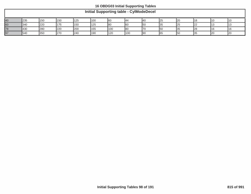
Initial Supporting table - CylModeDecelOBD GROUP:OBD GROUP: TESTTEST GROUP: G BIN4, FED---BIN4EMISSIONS STDS: Bin 440 235 150 150 125 100 60 44 40 25 20 18 10 1060 340 220 175 150 125 80 60 50 35 25 22 13 1378 430 280 220 200 155 100 80 70 50 35 28 16 1697 540 350 270 240 190 120 100 90 65 50 35 20 20
593
16 OBDG03 Initial Supporting Tables
Initial Supporting Tables 98 of 191 815 of 991

Initial Supporting table - CylModeJerkOBD GROUP:OBD GROUP: GGMXOB TESTTEST GROUP: G -BIN4, FED---BIN4EMISSIONS STDS: Bin 4
Description: Crankshaft jerk threshold. Thresholds are a function of rpm and % engine Load.
Notes: Used for P0300-P0308. Cal Name: KtMISF_ddt_CylinderMode
CylModeJerk - Part 1
y/x 400 500 600 700 800 900 1,000 1,100 1,200 1,400 1,600 1,800 2,0003 8,000 6,000 3,500 2,000 1,500 950 750 550 325 275 160 120 1006 8,000 7,000 4,000 2,400 1,900 1,300 900 700 500 325 250 175 1258 10,000 10,000 6,000 3,000 2,200 1,800 1,200 900 750 500 325 225 17510 12,000 12,000 8,000 4,000 2,800 2,200 1,600 1,400 900 600 400 275 21512 14,000 14,000 10,000 5,500 3,400 2,600 2,000 1,600 1,100 800 500 325 25014 16,000 16,000 12,000 7,000 4,000 3,000 2,400 2,000 1,400 850 600 375 30016 18,000 18,000 14,000 9,000 5,000 3,500 3,200 2,200 1,500 900 650 400 32518 20,000 20,000 16,000 10,500 6,000 4,000 3,800 2,400 1,800 1,100 750 435 35020 20,000 20,000 18,000 12,000 7,000 4,500 4,000 2,800 2,000 1,200 800 465 37522 20,000 20,000 20,000 14,000 8,000 5,000 4,400 3,200 2,300 1,250 850 500 40024 20,000 20,000 20,000 16,000 9,000 5,500 4,800 3,600 2,600 1,400 900 600 42526 20,000 20,000 20,000 18,000 10,000 6,000 5,500 4,000 3,000 1,500 1,000 650 48030 20,000 20,000 20,000 20,000 12,000 8,000 7,000 5,000 3,500 1,800 1,250 800 60040 20,000 20,000 20,000 20,000 14,000 10,000 9,000 6,500 4,000 2,400 1,500 975 75060 20,000 20,000 20,000 20,000 16,000 12,000 11,000 8,000 5,000 3,400 2,280 1,420 1,05078 20,000 20,000 20,000 20,000 18,000 14,000 13,000 10,000 7,000 4,400 3,000 1,800 1,33097 20,000 20,000 20,000 20,000 20,000 16,000 15,000 12,000 9,000 5,500 3,700 2,255 1,650
CylModeJerk - Part 2
y/x 2,200 2,400 2,600 2,800 3,000 3,500 4,000 4,500 5,000 5,500 6,000 6,500 7,0003 75 60 50 35 30 20 13 10 8 7 6 6 66 85 65 60 45 40 25 16 10 8 7 7 6 68 113 90 80 65 50 35 22 15 10 7 6 6 610 150 115 90 75 60 40 28 20 15 9 7 6 612 175 130 95 80 75 45 30 22 18 12 9 8 814 190 140 100 85 80 55 35 25 22 14 11 10 1016 200 150 110 90 85 60 38 28 23 16 14 11 1118 250 150 120 95 90 65 42 30 24 17 15 12 1220 275 175 135 100 95 70 47 32 25 18 16 12 1222 310 200 150 100 100 75 52 35 26 19 17 12 1224 350 250 180 125 115 80 55 38 27 20 18 13 1326 380 300 200 150 130 85 60 42 28 22 20 13 1330 420 350 250 250 185 95 65 55 35 25 22 14 14
594
16 OBDG03 Initial Supporting Tables
Initial Supporting Tables 99 of 191 816 of 991

Initial Supporting table - CylModeJerkOBD GROUP:OBD GROUP: TESTTEST GROUP: G -BIN4, FED---BIN4EMISSIONS STDS: Bin 440 555 420 300 300 225 120 75 65 45 35 25 15 1560 815 450 430 400 300 160 120 95 65 50 40 23 2378 1,045 780 550 520 400 225 150 120 80 65 50 28 2897 1,300 980 700 635 500 280 185 150 100 80 60 35 35
595
16 OBDG03 Initial Supporting Tables
Initial Supporting Tables 100 of 191 817 of 991

Initial Supporting table - EngineOverSpeedLimitOBD GROUP:OBD GROUP: TESTTEST GROUP: G IN4, FED---BIN4EMISSIONS STDS: Bin 4
Description: Engine OverSpeed Limit versus gear
Notes: Used for P0300-P0308. Cal Name: KaEOSC_n_EngOvrspdLimitGear
EngineOverSpeedLimit - Part 1
y/x CeTGRR_e_TransGr1 CeTGRR_e_TransGr2 CeTGRR_e_TransGr3 CeTGRR_e_TransGr4 CeTGRR_e_TransGr5 CeTGRR_e_TransGr6 CeTGRR_e_TransGrEVT1
1 6,900 6,900 6,900 6,900 6,900 6,900 6,900
EngineOverSpeedLimit - Part 2
y/x CeTGRR_e_TransGrEVT2
CeTGRR_e_TransGrNeut
CeTGRR_e_TransGrRvrs
CeTGRR_e_TransGrPark
CeTGRR_e_TransGr7 CeTGRR_e_TransGr8
1 6,900 4,000 6,900 4,000 6,900 6,900
596
16 OBDG03 Initial Supporting Tables
Initial Supporting Tables 101 of 191 818 of 991

Initial Supporting table - IdleCyl_DecelOBD GROUP:OBD GROUP: TESTTEST GROUP: G IN4, FED---BIN4EMISSIONS STDS: Bin 4
Description: Crankshaft decel threshold. Thresholds are a function of rpm and % engine Load.
Notes: Used for P0300-P0308. Cal Name: KtMSFD_dt_IdleCylinderMode
y/x 400 500 600 650 700 800 900 1,000 1,100 1,200 1,400 1,600 1,8003 6,000 6,000 3,500 2,550 1,600 1,200 700 500 400 300 250 150 1256 6,000 6,000 4,000 3,000 2,000 1,500 700 500 350 300 250 135 1008 7,000 6,000 4,000 3,000 2,000 1,500 800 600 400 350 235 150 10010 8,000 7,000 4,000 3,200 2,400 1,500 900 750 600 400 225 175 12512 9,000 8,000 4,000 3,250 2,500 1,500 1,000 850 700 450 250 200 15014 10,000 9,000 4,500 3,500 2,500 2,000 1,300 1,000 800 500 300 225 16516 10,000 10,000 5,000 3,875 2,750 2,000 1,500 1,200 900 550 350 250 18018 11,000 11,000 5,500 4,250 3,000 2,000 1,800 1,400 1,000 600 400 300 19020 12,000 12,000 6,000 4,750 3,500 2,500 2,000 1,500 1,100 700 450 350 20022 13,000 13,000 7,000 5,500 4,000 2,750 2,100 1,600 1,200 800 500 400 25024 14,000 14,000 7,500 6,000 4,500 3,000 2,200 1,700 1,300 1,000 600 400 30026 15,000 15,000 8,000 6,500 5,000 3,500 2,400 1,850 1,400 1,250 700 450 35028 15,500 15,500 8,500 7,000 5,500 3,750 2,600 1,975 1,600 1,275 750 475 37530 16,000 16,000 9,000 7,500 6,000 4,000 2,800 2,100 1,800 1,300 800 500 40032 16,200 16,200 9,400 7,850 6,300 4,300 2,940 2,240 1,940 1,320 845 526 41034 16,400 16,400 9,800 8,200 6,600 4,600 3,080 2,380 2,080 1,340 890 552 42036 16,600 16,600 10,200 8,550 6,900 4,900 3,220 2,520 2,220 1,360 935 578 430
597
16 OBDG03 Initial Supporting Tables
Initial Supporting Tables 102 of 191 819 of 991

Initial Supporting table - IdleCyl_JerkOBD GROUP:OBD GROUP: TESTTEST GROUP: G 4, FED---BIN4EMISSIONS STDS: Bin
Description: Crankshaft jerk threshold. Thresholds are a function of rpm and % engine Load.
Notes: Used for P0300-P0308. Cal Name: KtMSFD_ddt_IdleCylinderMode
y/x 400 500 600 650 700 800 900 1,000 1,100 1,200 1,400 1,600 1,8003 8,000 6,000 3,500 2,750 2,000 1,500 950 750 550 400 300 200 1506 8,000 7,000 4,000 3,200 2,400 1,800 1,100 900 700 500 300 200 1758 10,000 10,000 6,000 4,500 3,000 2,000 1,250 1,000 800 600 300 225 22510 12,000 12,000 8,000 6,000 4,000 2,500 1,300 1,100 900 700 300 250 25012 14,000 14,000 10,000 7,750 5,500 3,000 1,500 1,250 1,100 750 300 300 30014 16,000 16,000 12,000 9,500 7,000 4,000 2,000 1,500 1,300 800 350 350 35016 18,000 18,000 14,000 11,500 9,000 5,000 3,000 2,000 1,500 900 400 400 40018 20,000 20,000 16,000 13,250 10,500 6,000 4,000 3,000 2,000 1,000 500 450 43520 20,000 20,000 18,000 15,000 12,000 7,000 4,500 4,000 2,500 1,200 600 600 46522 20,000 20,000 20,000 17,000 14,000 8,000 5,000 4,400 3,000 1,400 750 750 50024 20,000 20,000 20,000 18,000 16,000 9,000 5,500 4,800 3,500 1,600 1,000 900 60026 20,000 20,000 20,000 19,000 18,000 10,000 6,000 5,500 4,000 2,000 1,250 1,000 65028 20,000 20,000 20,000 19,500 19,000 11,000 7,000 6,250 4,500 2,500 1,500 1,125 72530 20,000 20,000 20,000 20,000 20,000 12,000 8,000 7,000 5,000 3,000 1,800 1,250 80032 20,000 20,000 20,000 20,000 20,000 12,400 8,400 7,400 5,300 3,500 1,920 1,300 83534 20,000 20,000 20,000 20,000 20,000 12,800 8,800 7,800 5,600 3,700 2,040 1,350 87036 20,000 20,000 20,000 20,000 20,000 13,200 9,200 8,200 5,900 3,800 2,160 1,400 905
598
16 OBDG03 Initial Supporting Tables
Initial Supporting Tables 103 of 191 820 of 991
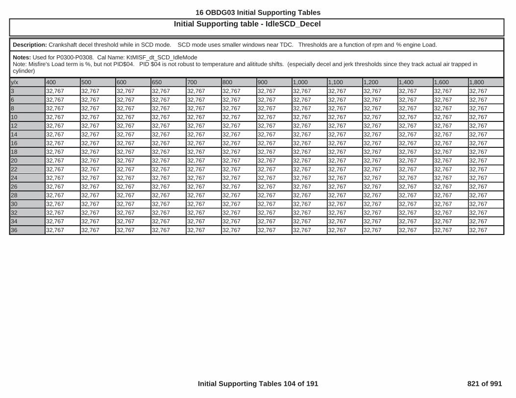
Initial Supporting table - IdleSCD_DecelOBD GROUP:OBD GROUP: TESTTEST GROUP: GG FED---BIN4EMISSIONS STDS: Bin 4
Description: Crankshaft decel threshold while in SCD mode. SCD mode uses smaller windows near TDC. Thresholds are a function of rpm and % engine Load.
Notes: Used for P0300-P0308. Cal Name: KtMISF_dt_SCD_IdleModeNote: Misfire's Load term is %, but not PID$04. PID $04 is not robust to temperature and alititude shifts. (especially decel and jerk thresholds since they track actual air trapped incylinder)
y/x 400 500 600 650 700 800 900 1,000 1,100 1,200 1,400 1,600 1,8003 32,767 32,767 32,767 32,767 32,767 32,767 32,767 32,767 32,767 32,767 32,767 32,767 32,7676 32,767 32,767 32,767 32,767 32,767 32,767 32,767 32,767 32,767 32,767 32,767 32,767 32,7678 32,767 32,767 32,767 32,767 32,767 32,767 32,767 32,767 32,767 32,767 32,767 32,767 32,76710 32,767 32,767 32,767 32,767 32,767 32,767 32,767 32,767 32,767 32,767 32,767 32,767 32,76712 32,767 32,767 32,767 32,767 32,767 32,767 32,767 32,767 32,767 32,767 32,767 32,767 32,76714 32,767 32,767 32,767 32,767 32,767 32,767 32,767 32,767 32,767 32,767 32,767 32,767 32,76716 32,767 32,767 32,767 32,767 32,767 32,767 32,767 32,767 32,767 32,767 32,767 32,767 32,76718 32,767 32,767 32,767 32,767 32,767 32,767 32,767 32,767 32,767 32,767 32,767 32,767 32,76720 32,767 32,767 32,767 32,767 32,767 32,767 32,767 32,767 32,767 32,767 32,767 32,767 32,76722 32,767 32,767 32,767 32,767 32,767 32,767 32,767 32,767 32,767 32,767 32,767 32,767 32,76724 32,767 32,767 32,767 32,767 32,767 32,767 32,767 32,767 32,767 32,767 32,767 32,767 32,76726 32,767 32,767 32,767 32,767 32,767 32,767 32,767 32,767 32,767 32,767 32,767 32,767 32,76728 32,767 32,767 32,767 32,767 32,767 32,767 32,767 32,767 32,767 32,767 32,767 32,767 32,76730 32,767 32,767 32,767 32,767 32,767 32,767 32,767 32,767 32,767 32,767 32,767 32,767 32,76732 32,767 32,767 32,767 32,767 32,767 32,767 32,767 32,767 32,767 32,767 32,767 32,767 32,76734 32,767 32,767 32,767 32,767 32,767 32,767 32,767 32,767 32,767 32,767 32,767 32,767 32,76736 32,767 32,767 32,767 32,767 32,767 32,767 32,767 32,767 32,767 32,767 32,767 32,767 32,767
599
16 OBDG03 Initial Supporting Tables
Initial Supporting Tables 104 of 191 821 of 991
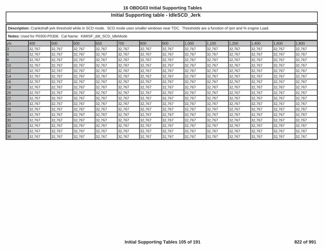
Initial Supporting table - IdleSCD_JerkOBD GROUP:OBD GROUP: TESTTEST GROUP: GG IN4, FED---BIN4EMISSIONS STDS: Bin 4
Description: Crankshaft jerk threshold while in SCD mode. SCD mode uses smaller windows near TDC. Thresholds are a function of rpm and % engine Load.
Notes: Used for P0300-P0308. Cal Name: KtMISF_ddt_SCD_IdleMode
y/x 400 500 600 650 700 800 900 1,000 1,100 1,200 1,400 1,600 1,8003 32,767 32,767 32,767 32,767 32,767 32,767 32,767 32,767 32,767 32,767 32,767 32,767 32,7676 32,767 32,767 32,767 32,767 32,767 32,767 32,767 32,767 32,767 32,767 32,767 32,767 32,7678 32,767 32,767 32,767 32,767 32,767 32,767 32,767 32,767 32,767 32,767 32,767 32,767 32,76710 32,767 32,767 32,767 32,767 32,767 32,767 32,767 32,767 32,767 32,767 32,767 32,767 32,76712 32,767 32,767 32,767 32,767 32,767 32,767 32,767 32,767 32,767 32,767 32,767 32,767 32,76714 32,767 32,767 32,767 32,767 32,767 32,767 32,767 32,767 32,767 32,767 32,767 32,767 32,76716 32,767 32,767 32,767 32,767 32,767 32,767 32,767 32,767 32,767 32,767 32,767 32,767 32,76718 32,767 32,767 32,767 32,767 32,767 32,767 32,767 32,767 32,767 32,767 32,767 32,767 32,76720 32,767 32,767 32,767 32,767 32,767 32,767 32,767 32,767 32,767 32,767 32,767 32,767 32,76722 32,767 32,767 32,767 32,767 32,767 32,767 32,767 32,767 32,767 32,767 32,767 32,767 32,76724 32,767 32,767 32,767 32,767 32,767 32,767 32,767 32,767 32,767 32,767 32,767 32,767 32,76726 32,767 32,767 32,767 32,767 32,767 32,767 32,767 32,767 32,767 32,767 32,767 32,767 32,76728 32,767 32,767 32,767 32,767 32,767 32,767 32,767 32,767 32,767 32,767 32,767 32,767 32,76730 32,767 32,767 32,767 32,767 32,767 32,767 32,767 32,767 32,767 32,767 32,767 32,767 32,76732 32,767 32,767 32,767 32,767 32,767 32,767 32,767 32,767 32,767 32,767 32,767 32,767 32,76734 32,767 32,767 32,767 32,767 32,767 32,767 32,767 32,767 32,767 32,767 32,767 32,767 32,76736 32,767 32,767 32,767 32,767 32,767 32,767 32,767 32,767 32,767 32,767 32,767 32,767 32,767
600
16 OBDG03 Initial Supporting Tables
Initial Supporting Tables 105 of 191 822 of 991

Initial Supporting table - Number of NormalsOBD GROUP:OBD GROUP: G TESTTEST GROUP: G -BIN4, FED---BIN4EMISSIONS STDS: Bin 4
Description: Number of Normals for the Driveline Ring FilterAfter a low level misfire, another misfire may not be detectable until driveline ringing ceases. If no ringing seen, stop filter early.
Notes: Used for P0300-P0308. Cal Name: KaMSFD_Cnt_NumOfNormalsFil
y/x 0 1 2 3 4 5 6 7 8
1 3.00 3.00 3.00 3.00 3.00 3.00 3.00 3.00 3.00
601
16 OBDG03 Initial Supporting Tables
Initial Supporting Tables 106 of 191 823 of 991

Initial Supporting table - P0089 - P163A - P228C - P228D - P0191 - KtFHPD_t_PumpCntrlEngRunThrshOBD GROUP:OBD GROUP: TESTTEST GROUP: G 4, FED---BIN4EMISSIONS STDS: Bin 4
Description: The High Pressure Control Performance Diagnostic and Pump Current Diagnostic will not run when the engine run time is below this timer following an engine start.
Notes:
y/x -30 -20 -10 0 10 20 80 100 110
1 120.0 120.0 120.0 120.0 120.0 120.0 120.0 120.0 120.0
602
16 OBDG03 Initial Supporting Tables
Initial Supporting Tables 107 of 191 824 of 991

Initial Supporting table - P00C6 - KtFHPC_p_HighPressStartOBD GROUP:OBD GROUP: TESTTEST GROUP: G ---BIN4, FED---BIN4EMISSIONS STDS: Bin 4
Description: This calibration is the minimum pressure in MPa that will exit High Pressure Start mode and allow fuel delivery
Notes:
y/x -40 -32 -24 -16 -8 0 8 16 20 24 32 40 48 64 80 96 1120 6.3 6.3 6.3 5.0 2.5 1.6 1.3 1.0 0.8 0.8 0.8 0.8 0.8 0.7 0.7 0.7 0.713 6.3 6.3 6.3 5.0 2.5 1.6 1.3 1.0 0.8 0.8 0.8 0.8 0.8 0.7 0.7 0.7 0.725 7.8 7.8 7.8 7.0 4.8 2.5 1.7 1.4 1.1 1.1 1.1 0.9 0.9 0.7 0.7 0.7 0.738 10.3 10.3 10.3 9.0 5.8 2.5 2.1 1.7 1.5 1.4 1.4 0.9 0.9 0.7 0.7 0.7 0.750 10.3 10.3 10.3 9.0 6.5 4.0 2.4 2.1 1.8 1.7 1.6 1.0 1.0 0.7 0.7 0.7 0.763 10.3 10.3 10.3 9.0 6.5 4.0 2.8 2.5 2.1 2.0 1.9 1.1 1.0 0.7 0.7 0.7 0.775 10.3 10.3 10.3 10.0 7.0 5.0 3.2 2.8 2.4 2.3 2.2 1.1 1.1 0.7 0.7 0.7 0.788 12.3 12.3 12.3 12.0 10.5 7.0 3.2 2.8 2.4 2.3 2.2 1.1 1.1 0.7 0.7 0.7 0.7100 12.3 12.3 12.3 12.0 10.5 7.0 3.2 2.8 2.4 2.3 2.2 1.1 1.1 0.7 0.7 0.7 0.7
603
16 OBDG03 Initial Supporting Tables
Initial Supporting Tables 108 of 191 825 of 991
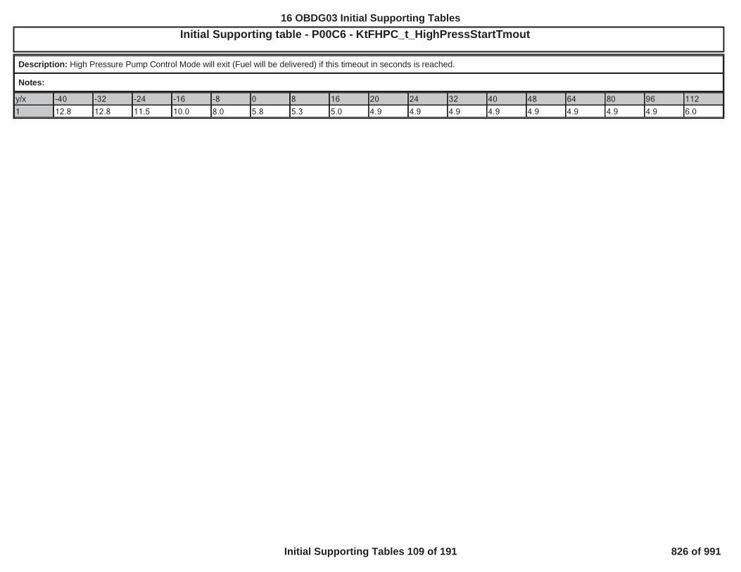
Initial Supporting table - P00C6 - KtFHPC_t_HighPressStartTmoutOBD GROUP:OBD GROUP: TESTTEST GROUP: G IN4, FED---BIN4EMISSIONS STDS: Bin 4
Description: High Pressure Pump Control Mode will exit (Fuel will be delivered) if this timeout in seconds is reached.
Notes:
y/x -40 -32 -24 -16 -8 0 8 16 20 24 32 40 48 64 80 96 112
1 12.8 12.8 11.5 10.0 8.0 5.8 5.3 5.0 4.9 4.9 4.9 4.9 4.9 4.9 4.9 4.9 6.0
604
16 OBDG03 Initial Supporting Tables
Initial Supporting Tables 109 of 191 826 of 991
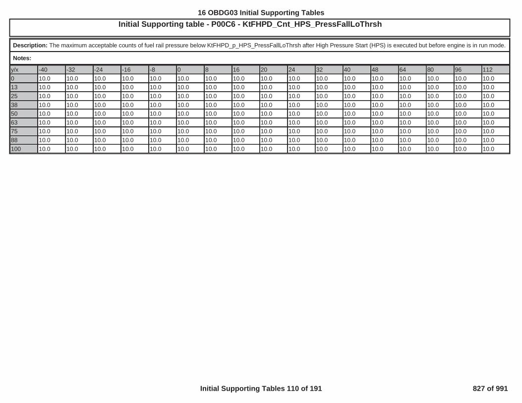
Initial Supporting table - P00C6 - KtFHPD_Cnt_HPS_PressFallLoThrshOBD GROUP:OBD GROUP: TESTTEST GROUP: GG IN4, FED---BIN4EMISSIONS STDS: Bin 4
Description: The maximum acceptable counts of fuel rail pressure below KtFHPD_p_HPS_PressFallLoThrsh after High Pressure Start (HPS) is executed but before engine is in run mode.
Notes:
y/x -40 -32 -24 -16 -8 0 8 16 20 24 32 40 48 64 80 96 1120 10.0 10.0 10.0 10.0 10.0 10.0 10.0 10.0 10.0 10.0 10.0 10.0 10.0 10.0 10.0 10.0 10.013 10.0 10.0 10.0 10.0 10.0 10.0 10.0 10.0 10.0 10.0 10.0 10.0 10.0 10.0 10.0 10.0 10.025 10.0 10.0 10.0 10.0 10.0 10.0 10.0 10.0 10.0 10.0 10.0 10.0 10.0 10.0 10.0 10.0 10.038 10.0 10.0 10.0 10.0 10.0 10.0 10.0 10.0 10.0 10.0 10.0 10.0 10.0 10.0 10.0 10.0 10.050 10.0 10.0 10.0 10.0 10.0 10.0 10.0 10.0 10.0 10.0 10.0 10.0 10.0 10.0 10.0 10.0 10.063 10.0 10.0 10.0 10.0 10.0 10.0 10.0 10.0 10.0 10.0 10.0 10.0 10.0 10.0 10.0 10.0 10.075 10.0 10.0 10.0 10.0 10.0 10.0 10.0 10.0 10.0 10.0 10.0 10.0 10.0 10.0 10.0 10.0 10.088 10.0 10.0 10.0 10.0 10.0 10.0 10.0 10.0 10.0 10.0 10.0 10.0 10.0 10.0 10.0 10.0 10.0100 10.0 10.0 10.0 10.0 10.0 10.0 10.0 10.0 10.0 10.0 10.0 10.0 10.0 10.0 10.0 10.0 10.0
605
16 OBDG03 Initial Supporting Tables
Initial Supporting Tables 110 of 191 827 of 991

Initial Supporting table - P00C6 - KtFHPD_p_HPS_PressFallLoThrshOBD GROUP:OBD GROUP: TESTTEST GROUP: G 4
Description: The minimum acceptable value of fuel rail pressure after High Pressure Start (HPS) is executed. This ensures the pressure does not fall off drastically after High PressureStart (HPS) is executed, but before engine is in run mode.
Notes: Axes are
y/x -40 -32 -24 -16 -8 0 8 16 20 24 32 40 48 64 80 96 1120 2.0 2.0 2.0 2.0 2.0 0.6 0.6 0.5 0.5 0.5 0.5 0.5 0.5 0.5 0.5 0.5 0.513 2.0 2.0 2.0 2.0 2.0 0.6 0.6 0.5 0.5 0.5 0.5 0.5 0.5 0.5 0.5 0.5 0.525 2.0 2.0 2.0 2.0 2.0 0.6 0.6 0.5 0.5 0.5 0.5 0.5 0.5 0.5 0.5 0.5 0.538 2.0 2.0 2.0 2.0 2.0 0.6 0.6 0.5 0.5 0.5 0.5 0.5 0.5 0.5 0.5 0.5 0.550 2.0 2.0 2.0 2.0 2.0 0.6 0.6 0.5 0.5 0.5 0.5 0.5 0.5 0.5 0.5 0.5 0.563 2.0 2.0 2.0 2.0 2.0 0.6 0.6 0.5 0.5 0.5 0.5 0.5 0.5 0.5 0.5 0.5 0.575 2.0 2.0 2.0 2.0 2.0 0.6 0.6 0.5 0.5 0.5 0.5 0.5 0.5 0.5 0.5 0.5 0.588 2.0 2.0 2.0 2.0 2.0 0.6 0.6 0.5 0.5 0.5 0.5 0.5 0.5 0.5 0.5 0.5 0.5100 2.0 2.0 2.0 2.0 2.0 0.6 0.6 0.5 0.5 0.5 0.5 0.5 0.5 0.5 0.5 0.5 0.5
606
16 OBDG03 Initial Supporting Tables
Initial Supporting Tables 111 of 191 828 of 991

Initial Supporting table - P0171_P0172_P0174_P0175 Long-Term Fuel Trim Cell UsageL---BIN4, FED---BIN4EMISSIONS STDS: Bin 4
Description: Identifies which Long Term Fuel Trim Cell I.D.s are used for diagnosis. Only cells identified as "CeFADD_e_NonSelectedCell" are not used for diagnosis.
Notes: DTCs: P0171, P0172, P0174, P0175; Calibration Name: KaFADD_e_SelectCellSet; Axis is Long Term Fuel Trim Cell I.D.
P0171_P0172_P0174_P0175 Long-Term Fuel Trim Cell Usage - Part 1
y/x CeFADR_e_Cell00_PurgOnAirMode5
CeFADR_e_Cell01_PurgOnAirMode4
CeFADR_e_Cell02_PurgOnAirMode3
CeFADR_e_Cell03_PurgOnAirMode2
1 CeFADD_e_SelectedPurgeCell CeFADD_e_SelectedPurgeCell CeFADD_e_SelectedPurgeCell CeFADD_e_SelectedPurgeCell
P0171_P0172_P0174_P0175 Long-Term Fuel Trim Cell Usage - Part 2
y/x CeFADR_e_Cell04_PurgOnAirMode1
CeFADR_e_Cell05_PurgOnAirMode0
CeFADR_e_Cell06_PurgOnIdle CeFADR_e_Cell07_PurgOnDecel
1 CeFADD_e_SelectedPurgeCell CeFADD_e_SelectedPurgeCell CeFADD_e_SelectedPurgeCell CeFADD_e_NonSelectedCell
P0171_P0172_P0174_P0175 Long-Term Fuel Trim Cell Usage - Part 3
y/x CeFADR_e_Cell08_PurgOffAirMode5
CeFADR_e_Cell09_PurgOffAirMode4
CeFADR_e_Cell10_PurgOffAirMode3
CeFADR_e_Cell11_PurgOffAirMode2
1 CeFADD_e_SelectedNonPurgeCell CeFADD_e_SelectedNonPurgeCell CeFADD_e_SelectedNonPurgeCell CeFADD_e_SelectedNonPurgeCell
P0171_P0172_P0174_P0175 Long-Term Fuel Trim Cell Usage - Part 4
y/x CeFADR_e_Cell12_PurgOffAirMode1
CeFADR_e_Cell13_PurgOffAirMode0
CeFADR_e_Cell14_PurgOffIdle CeFADR_e_Cell15_PurgOffDecel
1 CeFADD_e_SelectedNonPurgeCell CeFADD_e_SelectedNonPurgeCell CeFADD_e_SelectedNonPurgeCell CeFADD_e_NonSelectedCell
607
16 OBDG03 Initial Supporting Tables
Initial Supporting Tables 112 of 191 829 of 991

Initial Supporting table - P0191 - KtFHPD_Cnt_SnsPrfIdlePumpOffDlyOBD GROUP:OBD GROUP: G TESTTEST GROUP: G --BIN4, FED---BIN4EMISSIONS STDS: Bin 4
Description: The delay counter following the disabling of the high pressure pump used Only for the Sensor Performance Idle Test
Notes:
y/x 0 13 25 38 50 63 75 88 100
65 195.0 195.0 195.0 195.0 195.0 195.0 195.0 195.0 195.0
70 190.0 190.0 190.0 190.0 190.0 190.0 190.0 190.0 190.0
75 185.0 185.0 185.0 185.0 185.0 185.0 185.0 185.0 185.0
80 180.0 180.0 180.0 180.0 180.0 180.0 180.0 180.0 180.0
85 175.0 175.0 175.0 175.0 175.0 175.0 175.0 175.0 175.0
90 170.0 170.0 170.0 170.0 170.0 170.0 170.0 170.0 170.0
95 165.0 165.0 165.0 165.0 165.0 165.0 165.0 165.0 165.0
100 160.0 160.0 160.0 160.0 160.0 160.0 160.0 160.0 160.0
105 160.0 160.0 160.0 160.0 160.0 160.0 160.0 160.0 160.0
608
16 OBDG03 Initial Supporting Tables
Initial Supporting Tables 113 of 191 830 of 991

Initial Supporting table - P0191 - KtFHPD_t_SnsPrfStuckCrankTmoutOBD GROUP:OBD GROUP: TESTTEST GROUP: G BIN4, FED---BIN4EMISSIONS STDS: Bin 4
Description: The maximum crank time allowed before allowing the Sensor Performance Stuck Test to fail
Notes:
y/x -30 -20 -10 0 10 20 80 100 110
1 10.0 10.0 10.0 10.0 10.0 10.0 10.0 10.0 10.0
609
16 OBDG03 Initial Supporting Tables
Initial Supporting Tables 114 of 191 831 of 991

Initial Supporting table - P0234_KtBSTD_p_CntrlDevBasLimOBD GROUP:OBD GROUP: TESTTEST GROUP: G IN4, FED---BIN4EMISSIONS STDS: Bin 4
Description: Overboost in open loop diagnose failure limit.
Notes: X-Axis: KnBSTD_p_CntrlDevDiagAmbCorrBP - Ambient Air PressureY-Axis: KnBSTD_n_CntrlDevDiagAmbCorrBP - Engine Speed
y/x 60.0 70.0 80.0 90.0 100.0 110.01,500 90.000 90.000 80.000 70.000 60.000 60.0002,500 62.000 52.000 32.000 30.000 30.000 30.0003,000 42.000 25.000 10.000 10.000 10.000 10.0004,000 30.000 10.000 10.000 10.000 10.000 10.0005,000 30.000 10.000 10.000 10.000 10.000 10.0006,000 30.000 10.000 10.000 10.000 10.000 10.000
610
16 OBDG03 Initial Supporting Tables
Initial Supporting Tables 115 of 191 832 of 991

Initial Supporting table - P0299_KtBSTD_p_CntrlDevDsrdRtHiOBD GROUP:OBD GROUP: TESTTEST GROUP: GG --BIN4, FED---BIN4EMISSIONS STDS: Bin 4
Description: Allowed positive rate limit on desired boost pressure. In allowed kPa per 100 ms.
Notes: X-Axis: KnBSTD_n_CntrlDevDiagEngSpdBP - Engine Speed
y/x 1,000 1,500 2,000 2,500 3,000 3,500 4,000 4,500 5,000 6,000
1 2.000 2.500 2.700 2.900 3.000 3.000 3.100 3.200 3.500 4.000
611
16 OBDG03 Initial Supporting Tables
Initial Supporting Tables 116 of 191 833 of 991
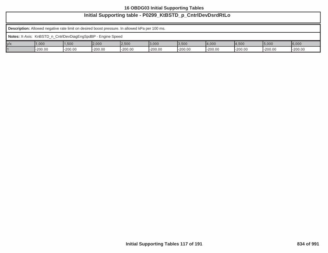
Initial Supporting table - P0299_KtBSTD_p_CntrlDevDsrdRtLoOBD GROUP:OBD GROUP: TESTTEST GROUP: G --BIN4, FED---BIN4EMISSIONS STDS: Bin 4
Description: Allowed negative rate limit on desired boost pressure. In allowed kPa per 100 ms.
Notes: X-Axis: KnBSTD_n_CntrlDevDiagEngSpdBP - Engine Speed
y/x 1,000 1,500 2,000 2,500 3,000 3,500 4,000 4,500 5,000 6,000
1 -200.00 -200.00 -200.00 -200.00 -200.00 -200.00 -200.00 -200.00 -200.00 -200.00
612
16 OBDG03 Initial Supporting Tables
Initial Supporting Tables 117 of 191 834 of 991

Initial Supporting table - P0324_PerCyl_ExcessiveKnock_ThresholdOBD GROUP:OBD GROUP: TESTTEST GROUP: G ---BIN4, FED---BIN4EMISSIONS STDS: Bin 4
Description: Fail threshold for the Knock Performance per-cylinder Excessive Knock Diagnostic
Notes: Used for P0324. Cal Name: KtKNKD_k_PerfCylFiltKnkIntThrsh. X-axis = Engine Speed (RPM), Diagnostic fails when VaKNKD_k_PerCylKnockIntFilt[cyl] >KtKNKD_k_PerfCylFiltKnkIntThrsh
y/x 500 1,000 1,500 2,000 2,500 3,000 3,500 4,000 4,500 5,000 5,500 6,000 6,500 7,000 7,500 8,000 8,5001 1.69 1.69 1.69 1.69 1.69 1.69 1.69 1.69 1.69 1.69 1.69 1.69 1.69 1.69 1.69 1.69 1.69
613
16 OBDG03 Initial Supporting Tables
Initial Supporting Tables 118 of 191 835 of 991

Initial Supporting table - P0325_P0330_OpenCktThrshMax (20 kHz)OBD GROUP:OBD GROUP: TESTTEST GROUP: G --BIN4, FED---BIN4EMISSIONS STDS: Bin 4
Description: Knock Open Circuit Diagnostic Maximum Threshold when using the 20 kHz method (see "OpenMethod" description)
Notes: Used for P0325 and P0330. Cal name: KtKNKD_k_OpenMax20K. x-axis = Engine Speed (RPM).
Diagnostic fails when the filtered diagnostic output is between the OpenCktThrshMin and OpenCktThrshMax:i.e.: KtKNKD_k_OpenMin20K < VaKNKD_k_OpenFiltIntensity < KtKNKD_k_OpenMax20K.
y/x 750 1,000 1,500 2,000 2,500 3,000 3,500 4,000 4,500 5,000 5,500 6,000 6,500 7,000 7,500 8,000 8,5001 8.0703 8.5195 8.5078 8.4121 8.4160 8.3320 8.4141 8.4141 8.7715 8.2207 8.0234 7.6289 7.2500 7.2500 7.2500 7.2500 7.2500
614
16 OBDG03 Initial Supporting Tables
Initial Supporting Tables 119 of 191 836 of 991

Initial Supporting table - P0325_P0330_OpenCktThrshMax (Normal Noise)OBD GROUP:OBD GROUP: G TESTTEST GROUP: G ---BIN4, FED---BIN4EMISSIONS STDS: Bin 4
Description: Knock Open Circuit Diagnostic Minimum Threshold when using the Normal Noise method (see "OpenMethod" description): When using the Normal Noise method (see"OpenMethod" description).
Notes: Used for P0325 and P0330. Cal name: KtKNKD_k_OpenMaxNN. x-axis = Engine Speed (RPM)
Diagnostic fails when the filtered diagnostic output is between the OpenCktThrshMin and OpenCktThrshMax:i.e.: KtKNKD_k_OpenMinNN < VaKNKD_k_OpenFiltIntensity < KtKNKD_k_OpenMaxNN.
y/x 2,700 2,900 3,000 3,250 3,500 3,750 4,000 4,250 4,500 4,750 5,000 5,500 6,000 6,500 7,000 7,500 8,5001 0.0000 0.0000 0.0000 0.0000 0.0000 0.0000 0.0000 0.0000 0.0000 0.0000 0.0000 0.0000 0.0000 0.0000 0.0000 0.0000 0.0000
615
16 OBDG03 Initial Supporting Tables
Initial Supporting Tables 120 of 191 837 of 991

Initial Supporting table - P0325_P0330_OpenCktThrshMin (20 kHz)OBD GROUP:OBD GROUP: TESTTEST GROUP: G --BIN4, FED---BIN4EMISSIONS STDS: Bin 4
Description: Knock Open Circuit Diagnostic Minimum Threshold when using the 20 kHz method (see "OpenMethod" description)
Notes: Used for P0325 and P0330. Cal name: KtKNKD_k_OpenMin20K. x-axis = Engine Speed (RPM)
Diagnostic fails when the filtered diagnostic output is between the OpenCktThrshMin and OpenCktThrshMax:i.e.: KtKNKD_k_OpenMin20K < VaKNKD_k_OpenFiltIntensity < KtKNKD_k_OpenMax20K.
y/x 750 1,000 1,500 2,000 2,500 3,000 3,500 4,000 4,500 5,000 5,500 6,000 6,500 7,000 7,500 8,000 8,5001 2.8887 3.0430 3.0410 2.9941 2.9902 2.9648 2.9961 2.9980 3.1523 2.9336 2.8887 2.7480 2.6309 2.6309 2.6309 2.6309 2.6309
616
16 OBDG03 Initial Supporting Tables
Initial Supporting Tables 121 of 191 838 of 991

Initial Supporting table - mP0325_P0330_OpenCktThrshMin (Nor al Noise)OBD GROUP:OBD GROUP: TESTTEST GROUP: G -BIN4, FED---BIN4EMISSIONS STDS: Bin 4
Description: Knock Open Circuit Diagnostic Minimum Threshold when using the Normal Noise method (see "OpenMethod" description): When using the Normal Noise method (see"OpenMethod" description).
Notes: Used for P0325 and P0330. Cal name: KtKNKD_k_OpenMinNN. x-axis = Engine Speed (RPM)
Diagnostic fails when the filtered diagnostic output is between the OpenCktThrshMin and OpenCktThrshMax:i.e.: KtKNKD_k_OpenMinNN < VaKNKD_k_OpenFiltIntensity < KtKNKD_k_OpenMaxNN.
y/x 2,700 2,900 3,000 3,250 3,500 3,750 4,000 4,250 4,500 4,750 5,000 5,500 6,000 6,500 7,000 7,500 8,5001 0.0000 0.0000 0.0000 0.0000 0.0000 0.0000 0.0000 0.0000 0.0000 0.0000 0.0000 0.0000 0.0000 0.0000 0.0000 0.0000 0.0000
617
16 OBDG03 Initial Supporting Tables
Initial Supporting Tables 122 of 191 839 of 991

Initial Supporting table - P0325_P0330_OpenMethod_2OBD GROUP:OBD GROUP: TESTTEST GROUP: GGMXT BIN4, FED---BIN4EMISSIONS STDS: Bin 4
Description: Defines which Knock Open Circuit Diagnostic method to use.
Notes: Used for P0325 and P0330. Cal name: KaKNKD_e_OpenMethod. x-axis = Engine Speed Index, 500 to 8500 (RPM) by 500 rpm increments.
Selects 1 of 3 available methods: "20kHz Method", "Normal Noise Method," or "None" (note: "None" = disabled at that rpm). The mode chosen dictates which set of threshold tables areused. Typically, either: A) the 20 kHz Method is used for all RPM or B) the 20 kHz Method is used for low/medium RPM and the Normal Noise Method is used for high RPM.
P0325_P0330_OpenMethod_2 - Part 1
y/x 0 1 2 3 41 CeKNKD_e_Open_20KHz CeKNKD_e_Open_20KHz CeKNKD_e_Open_20KHz CeKNKD_e_Open_20KHz CeKNKD_e_Open_20KHz
P0325_P0330_OpenMethod_2 - Part 2
y/x 5 6 7 8 91 CeKNKD_e_Open_20KHz CeKNKD_e_Open_20KHz CeKNKD_e_Open_20KHz CeKNKD_e_Open_20KHz CeKNKD_e_Open_20KHz
P0325_P0330_OpenMethod_2 - Part 3
y/x 10 11 12 13 141 CeKNKD_e_Open_20KHz CeKNKD_e_Open_20KHz CeKNKD_e_Open_20KHz CeKNKD_e_Open_20KHz CeKNKD_e_Open_20KHz
P0325_P0330_OpenMethod_2 - Part 4
y/x 15 161 CeKNKD_e_Open_20KHz CeKNKD_e_Open_20KHz
618
16 OBDG03 Initial Supporting Tables
Initial Supporting Tables 123 of 191 840 of 991

Initial Supporting table - P0326_P0331_AbnormalNoise_CylsEnabledOBD GROUP:OBD GROUP: TESTTEST GROUP: G -BIN4, FED---BIN4EMISSIONS STDS: Bin 4
Description: Specifies which cylinders will be used for the Abnormal Noise portion of the performance diagnostics (1 = cylinder used, 0 = cylinder not used)
Notes: Used for P0324, P0326 and P0331. Cal name: KaKNKD_b_PerfAbnIncludeCyl. x-axis = Cylinder number in firing order (i.e. Cyl 0 = first cylinder in firing order, Cyl 1 = secondcylinder in firing order....)
A cal value = 1 specifies the cylinder is used for the Abnormal Noise diagnostic. A cal value = 0 specifies the cylinder is not used. Only the first four values in the table are relavent for afour-cylinder engine and only the first six values in the table are relavent for a six-cylinder engine.
Typically, all cylinders are used. Cylinders are only excluded if the signal from that cylinder is weak and there is no separation between normal and faulted conditions (can occur if thesensor location results in poor signal-to-noise ratio for a given cylinder).
y/x 0 1 2 3 4 5 6 7
1 1 1 1 1 0 0 0 0
619
16 OBDG03 Initial Supporting Tables
Initial Supporting Tables 124 of 191 841 of 991
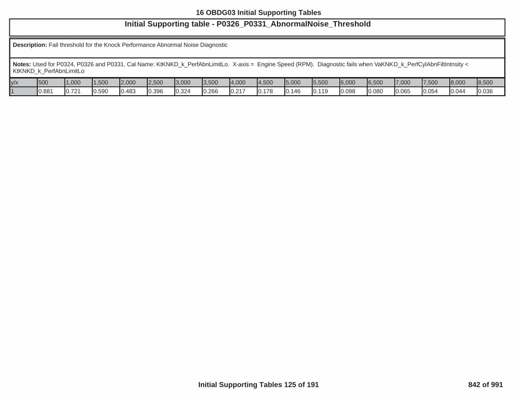
Initial Supporting table - P0326_P0331_AbnormalNoise_ThresholdOBD GROUP:OBD GROUP: L---BIN4, FED---BIN4EMISSIONS STDS: Bin
Description: Fail threshold for the Knock Performance Abnormal Noise Diagnostic
Notes: Used for P0324, P0326 and P0331. Cal Name: KtKNKD_k_PerfAbnLimitLo. X-axis = Engine Speed (RPM). Diagnostic fails when VaKNKD_k_PerfCylAbnFiltIntnsity <KtKNKD_k_PerfAbnLimitLo
y/x 500 1,000 1,500 2,000 2,500 3,000 3,500 4,000 4,500 5,000 5,500 6,000 6,500 7,000 7,500 8,000 8,5001 0.881 0.721 0.590 0.483 0.396 0.324 0.266 0.217 0.178 0.146 0.119 0.098 0.080 0.065 0.054 0.044 0.036
620
16 OBDG03 Initial Supporting Tables
Initial Supporting Tables 125 of 191 842 of 991

Initial Supporting table - P0442 Engine Off Time Before Vehicle Off Maximum as a Function of Estimated Ambient Temperature TableOBD GROUP: D2UB LTGOBD GROUP: GGMXOBDG03 --BIN4, FED---BIN4EMISSIONS STDS: Bin 4
Description: Data is Engine Off Time Before Vehicle Off Maximum Table (in seconds) and Axis is Estimated Ambient Coolant in Deg C
Notes: KtEONV_t_EngOffTimeBefVehOffMax
y/x -10 -4 1 7 13 18 24 29 35 41 46 52 58 63 69 74 801 44 44 44 44 68 82 105 153 320 480 480 480 480 480 480 480 480
621
16 OBDG03 Initial Supporting Tables
Initial Supporting Tables 126 of 191 843 of 991

Initial Supporting table - P0442 EONV Pressure Threshold (Pascals) TableOBD GROUP:OBD GROUP: TESTTEST GROUP: GG E--BIN4, FED---BIN4EMISSIONS STDS: Bin 4
Description: Data is EONV Pressure Threshold in Pascals, X axis (horizontal) is fuel level in % from 0 to 100 with step size 6.25, and Y axis (vertical) is temperature in deg C from -10 to80 with step size 5.625
Notes: KtEONV_p_PressureThreshold
y/x 1 2 3 4 5 6 7 8 9 10 11 12 13 14 15 16 171 -323.8 -323.8 -323.8 -323.8 -323.8 -323.8 -323.8 -323.8 -323.8 -323.8 -323.8 -323.8 -323.8 -323.8 -323.8 -323.8 -323.82 -323.8 -323.8 -323.8 -323.8 -323.8 -323.8 -323.8 -323.8 -323.8 -323.8 -323.8 -323.8 -323.8 -323.8 -323.8 -323.8 -323.83 -323.8 -323.8 -323.8 -323.8 -323.8 -323.8 -323.8 -323.8 -323.8 -323.8 -323.8 -323.8 -323.8 -323.8 -323.8 -323.8 -323.84 -323.8 -323.8 -323.8 -323.8 -323.8 -323.8 -323.8 -323.8 -323.8 -323.8 -323.8 -323.8 -323.8 -323.8 -323.8 -323.8 -323.85 -323.8 -323.8 -323.8 -323.8 -323.8 -323.8 -323.8 -323.8 -323.8 -323.8 -323.8 -323.8 -323.8 -323.8 -323.8 -323.8 -323.86 -323.8 -323.8 -323.8 -323.8 -323.8 -323.8 -323.8 -323.8 -323.8 -323.8 -323.8 -323.8 -323.8 -323.8 -323.8 -323.8 -323.87 -323.8 -323.8 -323.8 -323.8 -323.8 -323.8 -323.8 -323.8 -323.8 -323.8 -323.8 -323.8 -323.8 -323.8 -323.8 -323.8 -323.88 -323.8 -323.8 -323.8 -323.8 -323.8 -323.8 -323.8 -323.8 -323.8 -323.8 -323.8 -323.8 -323.8 -323.8 -323.8 -323.8 -323.89 -323.8 -323.8 -323.8 -323.8 -323.8 -323.8 -323.8 -323.8 -323.8 -323.8 -323.8 -323.8 -323.8 -323.8 -323.8 -323.8 -323.810 -323.8 -323.8 -323.8 -323.8 -323.8 -323.8 -323.8 -323.8 -323.8 -323.8 -323.8 -323.8 -323.8 -323.8 -323.8 -323.8 -323.811 -323.8 -323.8 -323.8 -323.8 -323.8 -323.8 -323.8 -323.8 -323.8 -323.8 -323.8 -323.8 -323.8 -323.8 -323.8 -323.8 -323.812 -323.8 -323.8 -323.8 -323.8 -323.8 -323.8 -323.8 -323.8 -323.8 -323.8 -323.8 -323.8 -323.8 -323.8 -323.8 -323.8 -323.813 -323.8 -323.8 -323.8 -323.8 -323.8 -323.8 -323.8 -323.8 -323.8 -323.8 -323.8 -323.8 -323.8 -323.8 -323.8 -323.8 -323.814 -323.8 -323.8 -323.8 -323.8 -323.8 -323.8 -323.8 -323.8 -323.8 -323.8 -323.8 -323.8 -323.8 -323.8 -323.8 -323.8 -323.815 -323.8 -323.8 -323.8 -323.8 -323.8 -323.8 -323.8 -323.8 -323.8 -323.8 -323.8 -323.8 -323.8 -323.8 -323.8 -323.8 -323.816 -323.8 -323.8 -323.8 -323.8 -323.8 -323.8 -323.8 -323.8 -323.8 -323.8 -323.8 -323.8 -323.8 -323.8 -323.8 -323.8 -323.817 -323.8 -323.8 -323.8 -323.8 -323.8 -323.8 -323.8 -323.8 -323.8 -323.8 -323.8 -323.8 -323.8 -323.8 -323.8 -323.8 -323.8
622
16 OBDG03 Initial Supporting Tables
Initial Supporting Tables 127 of 191 844 of 991

Initial Supporting table - P0442 Volatility Time as a Function of Estimate of Ambient TemperatureOBD GROUP:OBD GROUP: TESTTEST GROUP: G IN4, FED---BIN4EMISSIONS STDS: Bin 4
Description: Data is Volatility Time (in seconds) and Axis is Estimated Ambient Coolant in Deg C
Notes: KtEONV_t_VolatilityTimeMax
y/x -10 -4 1 7 13 18 24 29 35 41 46 52 58 63 69 74 801 30 30 45 60 80 120 220 300 400 400 400 400 400 400 400 400 400
623
16 OBDG03 Initial Supporting Tables
Initial Supporting Tables 128 of 191 845 of 991

Initial Supporting table - P0496 Purge Valve Leak Test Engine Vacuum Test Time (Cold Start) as a Function of Fuel Level TableOBD GROUP:OBD GROUP: TESTTEST GROUP: G IN4, FED---BIN4EMISSIONS STDS: Bin 4
Description: Data is Purge Valve Leak Test Engine Vacuum Test Time (in seconds) and Axis is Fuel Level in %
Notes: KtEVPD_t_PVLT_EngineVacTimeCold
y/x 0 6 12 19 25 31 37 44 50 56 62 69 75 81 87 94 1001 67 67 67 67 67 67 67 67 67 67 67 67 67 67 67 67 67
624
16 OBDG03 Initial Supporting Tables
Initial Supporting Tables 129 of 191 846 of 991

Initial Supporting table - P0521_LowMinOilPresFail - Two Stage Oil PumpOBD GROUP:OBD GROUP: TESTTEST GROUP: G 4, FED---BIN4EMISSIONS STDS: Bin 4
Description: Minimum expected oil presure readings
Notes: For P0521: KtLUBD_p_OP_SnsrMinOilPresFail with X Axis is defined by KnLUBD_n_OP_SnsrMinRPMAxs
y/x 1,000.0 1,500.0 2,000.0 2,500.0 3,000.0 3,500.0 4,000.0 4,500.0 5,000.0
1.0 125.1 188.7 197.2 211.4 224.3 231.3 237.2 244.4 250.0
625
16 OBDG03 Initial Supporting Tables
Initial Supporting Tables 130 of 191 847 of 991

Initial Supporting table - P0521_P06DD_P06DE_OP_HiStatePressureOBD GROUP:OBD GROUP: TESTTEST GROUP: G IN4, FED---BIN4EMISSIONS STDS: Bin 4
Description: Two Stage Oil Pump Oil Pressure in High State
Notes: For P0521, P06DD and P06DE: KtLUBD_p_OP_OilPresHighState with X Axis is defined by KnLUBD_n_OP_OilPresRPMAxs and Y Axis is defined byKnLUBD_T_OP_OilPresTempAxs
y/x 40.0 50.0 60.0 70.0 80.0 90.0 100.0 110.0 120.01,000.0 519.5 489.4 459.3 429.2 399.1 369.0 338.9 308.8 278.71,500.0 568.9 544.6 520.3 496.0 471.7 447.4 423.1 398.8 374.42,000.0 604.1 581.6 559.2 536.7 514.3 491.8 469.3 446.8 424.42,500.0 622.6 600.9 579.3 557.8 536.1 514.6 492.9 471.4 449.83,000.0 624.6 604.8 584.9 565.1 545.3 525.4 505.6 485.8 466.03,500.0 613.8 597.4 580.9 564.5 548.0 531.6 515.1 498.7 482.24,000.0 596.9 584.9 573.1 561.2 549.3 537.4 525.5 513.6 501.74,500.0 583.4 575.7 567.9 560.2 552.4 544.7 536.9 529.2 521.55,000.0 586.3 579.6 572.9 566.2 559.5 552.8 546.1 539.4 532.7
626
16 OBDG03 Initial Supporting Tables
Initial Supporting Tables 131 of 191 848 of 991

Initial Supporting table - P0606_Program Sequence Watch Enable f(Core, Loop Time)N4, FED---BIN4EMISSIONS STDS: Bin 4
Description: The enabling flags for the program sequence watch as a function of processor core and operating loop time sequence.
Notes: P0606, KaPISD_b_ProgSeqWatchEnbl
y/x CeTSKR_e_CPU CeTSKR_e_CPU2CePISR_e_6p25msSeq 1 1
CePISR_e_12p5msSeq 1 1
CePISR_e_25msSeq 1 1
CePISR_e_LORES_C 1 1
627
16 OBDG03 Initial Supporting Tables
Initial Supporting Tables 132 of 191 849 of 991

Initial Supporting table - P06B6_P06B7_OpenTestCktThrshMaxOBD GROUP:OBD GROUP: TESTTEST GROUP: G -BIN4, FED---BIN4EMISSIONS STDS: Bin 4
Description: Knock Open Circuit Minimum Threshold for Internal Circuit Diagnostic. Used only when the 20 kHz method is being used (see "OpenMethod" description). The Open TestCircuit ensures that the internal circuit used to generate the 20 kHz signal for the Open Circuit diags (P0325, P0330) is within range.
Notes: Used for P0325 and P0330. Cal name: KtKNKD_k_OpenTestCktMax. x-axis = Engine Speed (RPM).
Diagnostic fails when the filtered diagnostic output is between the OpenTestCktThrshMin and OpenTestCktThrshMax:i.e. KtKNKD_k_OpenTestCktMin < VaKNKD_k_OpenTestCktIntFilter < KtKNKD_k_OpenTestCktMax
y/x 750 1,000 1,500 2,000 2,500 3,000 3,500 4,000 4,500 5,000 5,500 6,000 6,500 7,000 7,500 8,000 8,5001 0.209 0.209 0.215 0.215 0.232 0.232 0.232 0.271 0.305 0.367 0.588 0.576 0.592 0.592 0.592 0.592 0.592
628
16 OBDG03 Initial Supporting Tables
Initial Supporting Tables 133 of 191 850 of 991
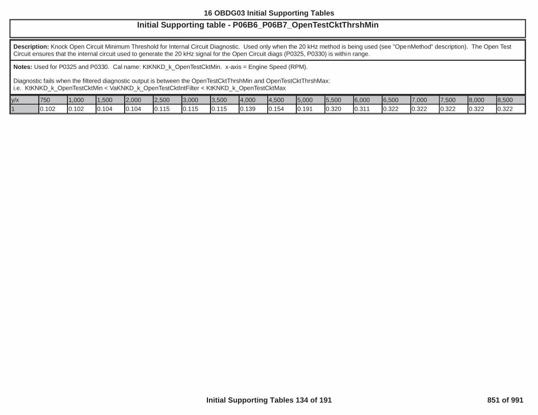
Initial Supporting table - P06B6_P06B7_OpenTestCktThrshMinOBD GROUP:OBD GROUP: TESTTEST GROUP: GG BIN4, FED---BIN4EMISSIONS STDS: Bin 4
Description: Knock Open Circuit Minimum Threshold for Internal Circuit Diagnostic. Used only when the 20 kHz method is being used (see "OpenMethod" description). The Open TestCircuit ensures that the internal circuit used to generate the 20 kHz signal for the Open Circuit diags (P0325, P0330) is within range.
Notes: Used for P0325 and P0330. Cal name: KtKNKD_k_OpenTestCktMin. x-axis = Engine Speed (RPM).
Diagnostic fails when the filtered diagnostic output is between the OpenTestCktThrshMin and OpenTestCktThrshMax:i.e. KtKNKD_k_OpenTestCktMin < VaKNKD_k_OpenTestCktIntFilter < KtKNKD_k_OpenTestCktMax
y/x 750 1,000 1,500 2,000 2,500 3,000 3,500 4,000 4,500 5,000 5,500 6,000 6,500 7,000 7,500 8,000 8,5001 0.102 0.102 0.104 0.104 0.115 0.115 0.115 0.139 0.154 0.191 0.320 0.311 0.322 0.322 0.322 0.322 0.322
629
16 OBDG03 Initial Supporting Tables
Initial Supporting Tables 134 of 191 851 of 991

Initial Supporting table - P06DD_P06DE_MaxEnableTorque_OPOBD GROUP:OBD GROUP: TESTTEST GROUP: G BIN4, FED---BIN4EMISSIONS STDS: Bin 4
Description: Two Stage Oil Pump Rationality Test Torque Max Enable Threshold
Notes: For P06DD and P06DE: KtLUBD_M_OP_InDiagEngTorqMax with X Axis is defined by KnLUBD_n_OP_InDiEngTorqMxRPMAxs
y/x 1,000.0 1,250.0 1,500.0 1,750.0 2,000.0 2,250.0 2,500.0 2,750.0 3,000.0
1.0 0.0 0.0 140.0 140.0 140.0 140.0 140.0 0.0 0.0
630
16 OBDG03 Initial Supporting Tables
Initial Supporting Tables 135 of 191 852 of 991

Initial Supporting table - P06DD_P06DE_MinEnableTorque_OPOBD GROUP:OBD GROUP: G TESTTEST GROUP: G L---BIN4, FED---BIN4EMISSIONS STDS: Bin
Description: Two Stage Oil Pump Rationality Test Torque Min Enable Threshold
Notes: For P06DD and P06DE: KtLUBD_M_OP_InDiagEngTorqMin with X Axis is defined by KnLUBD_n_OP_InDiEngTorqMnRPMAxs
y/x 1,000.0 1,250.0 1,500.0 1,750.0 2,000.0 2,250.0 2,500.0 2,750.0 3,000.0
1.0 0.0 0.0 20.0 20.0 20.0 20.0 20.0 0.0 0.0
631
16 OBDG03 Initial Supporting Tables
Initial Supporting Tables 136 of 191 853 of 991

Initial Supporting table - P06DD_P06DE_MinOilPressThreshOBD GROUP:OBD GROUP: TESTTEST GROUP: G BIN4, FED---BIN4EMISSIONS STDS: Bin 4
Description: Intrusive diagnostic minimum pressure limit that is a function of Engine Speed and Oil Temperature
Notes: For P06DD and P06DE: KtLUBD_p_InDiagMinPresThresh with X Axis is defined by KnLUBD_n_OP_OilPresRPMAxs and Y Axis is defined by KnLUBD_T_OP_OilPresTempAxs
y/x 40 50 60 70 80 90 100 110 1201,000 25 32 38 45 52 59 65 68 711,500 25 32 38 45 52 59 65 68 712,000 25 32 38 45 52 59 65 68 712,500 25 32 38 45 52 59 65 68 713,000 25 32 38 45 52 59 65 68 713,500 25 32 38 45 52 59 65 68 714,000 25 32 38 45 52 59 65 68 714,500 25 32 38 45 52 59 65 68 715,000 25 32 38 45 52 59 65 68 71
632
16 OBDG03 Initial Supporting Tables
Initial Supporting Tables 137 of 191 854 of 991
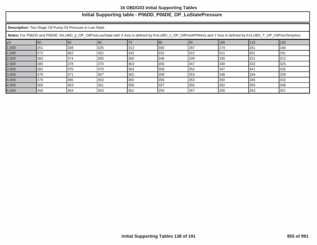
Initial Supporting table - P06DD_P06DE_OP_LoStatePressureOBD GROUP:OBD GROUP: TESTTEST GROUP: G -BIN4, FED---BIN4EMISSIONS STDS: Bin 4
Description: Two Stage Oil Pump Oil Pressure in Low State
Notes: For P06DD and P06DE: KtLUBD_p_OP_OilPresLowState with X Axis is defined by KnLUBD_n_OP_OilPresRPMAxs and Y Axis is defined by KnLUBD_T_OP_OilPresTempAxs
y/x 40 50 60 70 80 90 100 110 1201,000 351 338 325 313 300 287 274 261 2481,500 372 362 352 342 332 322 311 301 2912,000 383 374 365 356 348 339 330 321 3122,500 385 378 370 363 355 347 340 332 3253,000 382 376 370 364 358 352 347 341 3353,500 376 371 367 362 358 353 348 344 3394,000 370 366 363 360 356 353 350 346 3434,500 365 363 361 359 357 355 352 350 3485,000 366 364 363 361 359 357 355 353 351
633
16 OBDG03 Initial Supporting Tables
Initial Supporting Tables 138 of 191 855 of 991

Initial Supporting table - P06DD_P06DE_OP_StateChangeMinOBD GROUP:OBD GROUP: TESTTEST GROUP: G BIN4, FED---BIN4EMISSIONS STDS: Bin 4
Description: Minimum allowed pressure change on a Two Stage Oil Pump state change
Notes: For P06DD and P06DE: KtLUBD_p_OP_StateChangeMin with X Axis is defined by KnLUBD_n_OP_OilPresRPMAxs and Y Axis is defined by KnLUBD_T_OP_OilPresTempAxs
y/x 40.0 50.0 60.0 70.0 80.0 90.0 100.0 110.0 120.01,000.0 80.0 50.0 42.0 35.0 28.0 21.0 14.0 6.0 0.01,500.0 79.0 72.0 65.0 58.0 51.0 44.0 36.0 29.0 22.02,000.0 91.0 84.0 77.0 70.0 62.0 55.0 49.0 41.0 34.02,500.0 97.0 90.0 84.0 77.0 70.0 64.0 57.0 51.0 44.03,000.0 99.0 93.0 87.0 81.0 75.0 69.0 62.0 56.0 50.03,500.0 103.0 98.0 92.0 87.0 81.0 75.0 70.0 65.0 59.04,000.0 105.0 101.0 96.0 92.0 88.0 84.0 80.0 76.0 72.04,500.0 105.0 102.0 99.0 96.0 93.0 90.0 87.0 85.0 82.05,000.0 106.0 105.0 102.0 100.0 98.0 96.0 94.0 92.0 90.0
634
16 OBDG03 Initial Supporting Tables
Initial Supporting Tables 139 of 191 856 of 991

Initial Supporting table - P171D hydraulic pressure delayOBD GROUP:OBD GROUP: TESTTEST GROUP: G IN4, FED---BIN4EMISSIONS STDS: Bin 4
Description: Time to delay the initial x of y counter due to hydraulic transients. Thresholds are a function of transmission fluid temperature. Horizontal axis is transmission fluidtemperature (DegC) and table output is delay time (seconds).
Notes: KtTAPD_t_PERF_HydPresDelayTmr
y/x -40.00 0.00 20.00 30.00 40.00 50.00 60.00
1.00 0.09 0.09 0.08 0.08 0.08 0.08 0.08
635
16 OBDG03 Initial Supporting Tables
Initial Supporting Tables 140 of 191 857 of 991

Initial Supporting table - P171D predicted turbine speed errorOBD GROUP:OBD GROUP: TESTTEST GROUP: GGMX ---BIN4, FED---BIN4EMISSIONS STDS: Bin 4
Description: Predicted turbine speed vs actual turbine speed error. Thresholds are a function of engine speed and transmission fliud temperature. Diagnostic is considered failing abovethese values. Table vertical axis is engine speed (RPM), horizontal axis is transmission fluid temperature (DegC) and table output is predicted turbine speed error (RPM).
Notes: KtTAPD_n_PERF_TurbSpdFailThsh
y/x -40.00 0.00 10.00 20.00 40.00
0.00 350.00 350.00 350.00 350.00 350.00
500.00 350.00 350.00 350.00 350.00 350.00
1,100.00 350.00 350.00 350.00 350.00 350.00
1,500.00 350.00 350.00 350.00 350.00 350.00
2,500.00 350.00 350.00 350.00 350.00 350.00
636
16 OBDG03 Initial Supporting Tables
Initial Supporting Tables 141 of 191 858 of 991

Initial Supporting table - P171D transmission forward gear ratiosOBD GROUP:OBD GROUP: TESTTEST GROUP: G E4, FED---BIN4EMISSIONS STDS: Bin 4
Description: Transmission forward gear ratio's (1-6). These values represent the nominal forward gear ratios. These values are used along with the following calibrations to define thevalid ratio bands. Units are ratio.
KeCSSD_pct_RVT_1stHighMultKeCSSD_pct_RVT_1stLowMultKeCSSD_pct_RVT_HighMultKeCSSD_pct_RVT_LowMult
Notes: KaTAPD_r_TransRatios(x)
y/x 0.00 1.00 2.00 3.00 4.00 5.001.00 4.53 2.91 1.88 1.43 1.00 0.75
637
16 OBDG03 Initial Supporting Tables
Initial Supporting Tables 142 of 191 859 of 991

Initial Supporting table - P219A Normalizer Bank1 TableOBD GROUP:OBD GROUP: TESTTEST GROUP: G L---BIN4, FED---BIN4EMISSIONS STDS: Bin 4
Description: Bank 1 Normalizer table used in the calculation of the Ratio for the current sample period.
Notes: DTCs: P219A; Calibration Name: KtFABD_U_Normalizer1; Horizontal axis is RPM; Vertical Axis is Air Per Cylinder (APC) in mg/cylinder
y/x 250 500 750 1,000 1,250 1,500 1,750 2,000 2,250 2,500 2,750 3,000 3,500 4,000 4,500 5,000 6,00040 0.00 0.00 0.00 0.00 0.00 0.00 0.00 0.00 0.00 0.00 0.00 0.00 0.00 0.00 0.00 0.00 0.0080 0.00 0.00 0.00 0.00 0.00 0.00 0.00 0.00 0.00 0.00 0.00 0.00 0.00 0.00 0.00 0.00 0.00120 0.00 0.00 0.00 0.00 0.00 0.00 0.00 0.00 0.00 0.00 0.00 0.00 0.00 0.00 0.00 0.00 0.00160 0.00 0.00 0.00 0.00 0.00 0.00 0.00 0.00 0.00 0.00 0.00 0.00 0.00 0.00 0.00 0.00 0.00200 0.00 0.00 0.00 15.00 6.25 11.75 0.00 0.00 0.00 0.00 0.00 0.00 0.00 0.00 0.00 0.00 0.00240 0.00 0.00 0.00 0.00 45.00 52.00 41.50 13.75 13.50 17.00 17.50 0.00 3.00 0.00 0.00 0.00 0.00280 0.00 0.00 0.00 0.00 86.75 91.25 82.75 38.25 43.50 40.50 40.00 12.00 19.50 0.00 0.00 0.00 0.00320 0.00 0.00 0.00 0.00 149.00 106.50 92.75 55.00 67.00 63.25 59.50 34.00 41.50 0.00 0.00 0.00 0.00360 0.00 0.00 0.00 0.00 182.75 147.00 108.00 83.50 90.75 76.25 65.00 47.75 51.00 0.00 0.00 0.00 0.00400 0.00 0.00 0.00 0.00 217.75 182.25 146.00 115.00 109.25 96.50 78.50 70.00 51.00 0.00 0.00 0.00 0.00440 0.00 0.00 0.00 0.00 227.50 207.50 182.50 137.75 122.25 117.00 95.50 85.25 0.00 0.00 0.00 0.00 0.00480 0.00 0.00 0.00 0.00 245.25 241.00 213.75 158.50 142.50 123.00 109.50 0.00 0.00 0.00 0.00 0.00 0.00520 0.00 0.00 0.00 0.00 264.50 231.50 227.25 179.50 151.25 136.50 119.50 0.00 0.00 0.00 0.00 0.00 0.00560 0.00 0.00 0.00 0.00 0.00 0.00 0.00 0.00 0.00 0.00 0.00 0.00 0.00 0.00 0.00 0.00 0.00640 0.00 0.00 0.00 0.00 0.00 0.00 0.00 0.00 0.00 0.00 0.00 0.00 0.00 0.00 0.00 0.00 0.00720 0.00 0.00 0.00 0.00 0.00 0.00 0.00 0.00 0.00 0.00 0.00 0.00 0.00 0.00 0.00 0.00 0.00820 0.00 0.00 0.00 0.00 0.00 0.00 0.00 0.00 0.00 0.00 0.00 0.00 0.00 0.00 0.00 0.00 0.00
638
16 OBDG03 Initial Supporting Tables
Initial Supporting Tables 143 of 191 860 of 991

Initial Supporting table - P219A Quality Factor Bank1 TableOBD GROUP:OBD GROUP: TESTTEST GROUP: G --BIN4, FED---BIN4EMISSIONS STDS: Bin 4
Description: Bank 1 lookup table of Quality Factors used in the calculation of the Ratio for the current sample period
Notes: DTCs: P219A; Calibration Name: KtFABD_K_QualFactor1; Horizontal axis is RPM; Vertical Axis is Air Per Cylinder (APC) in mg/cylinder
y/x 250 500 750 1,000 1,250 1,500 1,750 2,000 2,250 2,500 2,750 3,000 3,500 4,000 4,500 5,000 6,00040 0.00 0.00 0.00 0.00 0.00 0.00 0.00 0.00 0.00 0.00 0.00 0.00 0.00 0.00 0.00 0.00 0.0080 0.00 0.00 0.00 0.00 0.00 0.00 0.00 0.00 0.00 0.00 0.00 0.00 0.00 0.00 0.00 0.00 0.00120 0.00 0.00 0.00 0.00 0.00 0.00 0.00 0.00 0.00 0.00 0.00 0.00 0.00 0.00 0.00 0.00 0.00160 0.00 0.00 0.00 0.00 0.00 0.00 0.00 0.00 0.00 0.00 0.00 0.00 0.00 0.00 0.00 0.00 0.00200 0.00 0.00 0.00 1.00 1.00 1.00 0.00 0.00 0.00 0.00 0.00 0.00 0.00 0.00 0.00 0.00 0.00240 0.00 0.00 0.00 0.00 1.00 1.00 1.00 1.00 1.00 1.00 1.00 0.00 1.00 0.00 0.00 0.00 0.00280 0.00 0.00 0.00 0.00 1.00 1.00 1.00 1.00 1.00 1.00 1.00 1.00 1.00 0.00 0.00 0.00 0.00320 0.00 0.00 0.00 0.00 1.00 1.00 1.00 1.00 1.00 1.00 1.00 1.00 1.00 0.00 0.00 0.00 0.00360 0.00 0.00 0.00 0.00 1.00 1.00 1.00 1.00 1.00 1.00 1.00 1.00 1.00 0.00 0.00 0.00 0.00400 0.00 0.00 0.00 0.00 1.00 1.00 1.00 1.00 1.00 1.00 1.00 1.00 1.00 0.00 0.00 0.00 0.00440 0.00 0.00 0.00 0.00 1.00 1.00 1.00 1.00 1.00 1.00 1.00 1.00 0.00 0.00 0.00 0.00 0.00480 0.00 0.00 0.00 0.00 1.00 1.00 1.00 1.00 1.00 1.00 1.00 0.00 0.00 0.00 0.00 0.00 0.00520 0.00 0.00 0.00 0.00 1.00 1.00 1.00 1.00 1.00 1.00 1.00 0.00 0.00 0.00 0.00 0.00 0.00560 0.00 0.00 0.00 0.00 0.00 0.00 0.00 0.00 0.00 0.00 0.00 0.00 0.00 0.00 0.00 0.00 0.00640 0.00 0.00 0.00 0.00 0.00 0.00 0.00 0.00 0.00 0.00 0.00 0.00 0.00 0.00 0.00 0.00 0.00720 0.00 0.00 0.00 0.00 0.00 0.00 0.00 0.00 0.00 0.00 0.00 0.00 0.00 0.00 0.00 0.00 0.00820 0.00 0.00 0.00 0.00 0.00 0.00 0.00 0.00 0.00 0.00 0.00 0.00 0.00 0.00 0.00 0.00 0.00
639
16 OBDG03 Initial Supporting Tables
Initial Supporting Tables 144 of 191 861 of 991

Initial Supporting table - P219A Variance Threshold Bank1 TableOBD GROUP:OBD GROUP: G TESTTEST GROUP: G E--BIN4, FED---BIN4EMISSIONS STDS: Bin 4
Description: Bank 1 lookup table of Variance metric used to calculate the Ratio for the current sample period
Notes: DTCs: P219A; Calibration Name: KtFABD_U_VarThresh1; Horizontal axis is RPM; Vertical Axis is Air Per Cylinder (APC) in mg/cylinder
y/x 250 500 750 1,000 1,250 1,500 1,750 2,000 2,250 2,500 2,750 3,000 3,500 4,000 4,500 5,000 6,00040 9,999.00 9,999.00 9,999.00 9,999.00 9,999.00 9,999.00 9,999.00 9,999.00 9,999.00 9,999.00 9,999.00 9,999.00 9,999.00 9,999.00 9,999.00 9,999.00 9,999.0080 9,999.00 9,999.00 9,999.00 9,999.00 9,999.00 9,999.00 9,999.00 9,999.00 9,999.00 9,999.00 9,999.00 9,999.00 9,999.00 9,999.00 9,999.00 9,999.00 9,999.00120 9,999.00 9,999.00 9,999.00 9,999.00 9,999.00 9,999.00 9,999.00 9,999.00 9,999.00 9,999.00 9,999.00 9,999.00 9,999.00 9,999.00 9,999.00 9,999.00 9,999.00160 9,999.00 9,999.00 9,999.00 9,999.00 9,999.00 9,999.00 9,999.00 9,999.00 9,999.00 9,999.00 9,999.00 9,999.00 9,999.00 9,999.00 9,999.00 9,999.00 9,999.00200 9,999.00 9,999.00 9,999.00 12.00 8.50 9.00 9,999.00 9,999.00 9,999.00 9,999.00 9,999.00 9,999.00 9,999.00 9,999.00 9,999.00 9,999.00 9,999.00240 9,999.00 9,999.00 9,999.00 9,999.00 12.75 13.50 7.75 20.00 7.25 8.00 6.75 9,999.00 7.75 9,999.00 9,999.00 9,999.00 9,999.00280 9,999.00 9,999.00 9,999.00 9,999.00 21.50 17.00 14.00 25.75 8.50 7.75 8.50 28.25 6.50 9,999.00 9,999.00 9,999.00 9,999.00320 9,999.00 9,999.00 9,999.00 9,999.00 20.25 25.50 14.75 33.00 14.00 13.00 11.00 26.00 11.50 9,999.00 9,999.00 9,999.00 9,999.00360 9,999.00 9,999.00 9,999.00 9,999.00 44.00 30.50 20.25 36.00 22.50 18.75 14.50 24.50 12.25 9,999.00 9,999.00 9,999.00 9,999.00400 9,999.00 9,999.00 9,999.00 9,999.00 40.25 34.00 32.50 38.50 27.00 19.50 16.25 22.00 11.00 9,999.00 9,999.00 9,999.00 9,999.00440 9,999.00 9,999.00 9,999.00 9,999.00 47.75 41.75 32.75 40.50 30.25 19.25 18.00 20.00 9,999.00 9,999.00 9,999.00 9,999.00 9,999.00480 9,999.00 9,999.00 9,999.00 9,999.00 45.50 35.00 37.00 49.50 24.00 22.50 18.25 9,999.00 9,999.00 9,999.00 9,999.00 9,999.00 9,999.00520 9,999.00 9,999.00 9,999.00 9,999.00 57.00 42.50 39.75 46.25 35.00 30.25 25.50 9,999.00 9,999.00 9,999.00 9,999.00 9,999.00 9,999.00560 9,999.00 9,999.00 9,999.00 9,999.00 9,999.00 9,999.00 9,999.00 9,999.00 9,999.00 9,999.00 0.00 0.00 0.00 0.00 0.00 0.00 0.00640 0.00 0.00 0.00 0.00 0.00 0.00 0.00 0.00 0.00 0.00 0.00 0.00 0.00 0.00 0.00 0.00 0.00720 0.00 0.00 0.00 0.00 0.00 0.00 0.00 0.00 0.00 0.00 0.00 0.00 0.00 0.00 0.00 0.00 0.00820 0.00 0.00 0.00 0.00 0.00 0.00 0.00 0.00 0.00 0.00 0.00 0.00 0.00 0.00 0.00 0.00 0.00
640
16 OBDG03 Initial Supporting Tables
Initial Supporting Tables 145 of 191 862 of 991
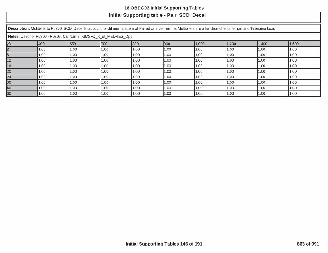
Initial Supporting table - Pair_SCD_DecelOBD GROUP:OBD GROUP: GG TESTTEST GROUP: G ---BIN4, FED---BIN4EMISSIONS STDS: Bin 4
Description: Mulitplier to P0300_SCD_Decel to account for different pattern of Paired cylinder misfire. Multipliers are a function of engine rpm and % engine Load.
Notes: Used for P0300 - P0308, Cal Name: KtMSFD_K_dt_MEDRES_Opp
y/x 400 550 700 800 900 1,000 1,200 1,400 1,6002 1.00 1.00 1.00 1.00 1.00 1.00 1.00 1.00 1.008 1.00 1.00 1.00 1.00 1.00 1.00 1.00 1.00 1.0012 1.00 1.00 1.00 1.00 1.00 1.00 1.00 1.00 1.0016 1.00 1.00 1.00 1.00 1.00 1.00 1.00 1.00 1.0020 1.00 1.00 1.00 1.00 1.00 1.00 1.00 1.00 1.0024 1.00 1.00 1.00 1.00 1.00 1.00 1.00 1.00 1.0030 1.00 1.00 1.00 1.00 1.00 1.00 1.00 1.00 1.0040 1.00 1.00 1.00 1.00 1.00 1.00 1.00 1.00 1.0060 1.00 1.00 1.00 1.00 1.00 1.00 1.00 1.00 1.00
641
16 OBDG03 Initial Supporting Tables
Initial Supporting Tables 146 of 191 863 of 991

Initial Supporting table - Pair_SCD_JerkOBD GROUP:OBD GROUP: TESTTEST GROUP: GG BIN4, FED---BIN4EMISSIONS STDS: Bin 4
Description: Mulitplier to P0300_SCD_Jerk to account for different pattern of Paired cylinder misfire. Multipliers are a function of engine rpm and % engine Load.
Notes: Used for P0300 - P0308, Cal Name: KtMSFD_K_ddt_MEDRES_Opp
y/x 400 550 700 800 900 1,000 1,200 1,400 1,6002 1.00 1.00 1.00 1.00 1.00 1.00 1.00 1.00 1.008 1.00 1.00 1.00 1.00 1.00 1.00 1.00 1.00 1.0012 1.00 1.00 1.00 1.00 1.00 1.00 1.00 1.00 1.0016 1.00 1.00 1.00 1.00 1.00 1.00 1.00 1.00 1.0020 1.00 1.00 1.00 1.00 1.00 1.00 1.00 1.00 1.0024 1.00 1.00 1.00 1.00 1.00 1.00 1.00 1.00 1.0030 1.00 1.00 1.00 1.00 1.00 1.00 1.00 1.00 1.0040 1.00 1.00 1.00 1.00 1.00 1.00 1.00 1.00 1.0060 1.00 1.00 1.00 1.00 1.00 1.00 1.00 1.00 1.00
642
16 OBDG03 Initial Supporting Tables
Initial Supporting Tables 147 of 191 864 of 991
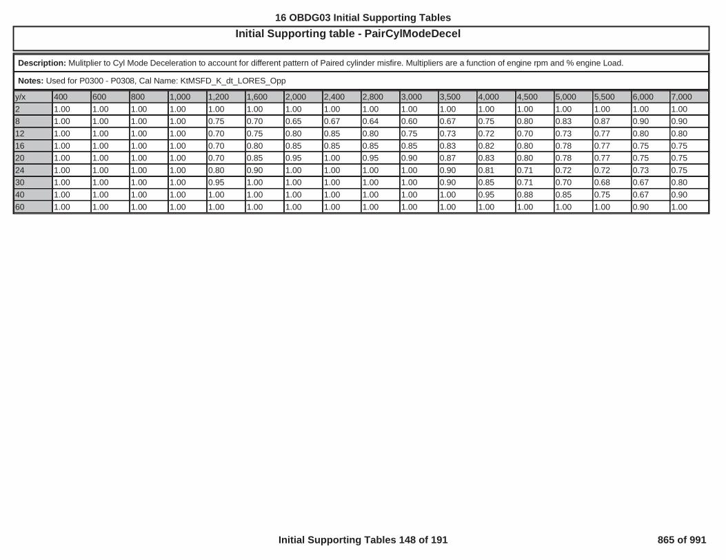
Initial Supporting table - PairCylModeDecelOBD GROUP:OBD GROUP: TESTTEST GROUP: GG ---BIN4, FED---BIN4EMISSIONS STDS: Bin 4
Description: Mulitplier to Cyl Mode Deceleration to account for different pattern of Paired cylinder misfire. Multipliers are a function of engine rpm and % engine Load.
Notes: Used for P0300 - P0308, Cal Name: KtMSFD_K_dt_LORES_Opp
y/x 400 600 800 1,000 1,200 1,600 2,000 2,400 2,800 3,000 3,500 4,000 4,500 5,000 5,500 6,000 7,0002 1.00 1.00 1.00 1.00 1.00 1.00 1.00 1.00 1.00 1.00 1.00 1.00 1.00 1.00 1.00 1.00 1.008 1.00 1.00 1.00 1.00 0.75 0.70 0.65 0.67 0.64 0.60 0.67 0.75 0.80 0.83 0.87 0.90 0.9012 1.00 1.00 1.00 1.00 0.70 0.75 0.80 0.85 0.80 0.75 0.73 0.72 0.70 0.73 0.77 0.80 0.8016 1.00 1.00 1.00 1.00 0.70 0.80 0.85 0.85 0.85 0.85 0.83 0.82 0.80 0.78 0.77 0.75 0.7520 1.00 1.00 1.00 1.00 0.70 0.85 0.95 1.00 0.95 0.90 0.87 0.83 0.80 0.78 0.77 0.75 0.7524 1.00 1.00 1.00 1.00 0.80 0.90 1.00 1.00 1.00 1.00 0.90 0.81 0.71 0.72 0.72 0.73 0.7530 1.00 1.00 1.00 1.00 0.95 1.00 1.00 1.00 1.00 1.00 0.90 0.85 0.71 0.70 0.68 0.67 0.8040 1.00 1.00 1.00 1.00 1.00 1.00 1.00 1.00 1.00 1.00 1.00 0.95 0.88 0.85 0.75 0.67 0.9060 1.00 1.00 1.00 1.00 1.00 1.00 1.00 1.00 1.00 1.00 1.00 1.00 1.00 1.00 1.00 0.90 1.00
643
16 OBDG03 Initial Supporting Tables
Initial Supporting Tables 148 of 191 865 of 991

Initial Supporting table - PairCylModeJerkOBD GROUP:OBD GROUP: GGMX TESTTEST GROUP: G IN4, FED---BIN4EMISSIONS STDS: Bin 4
Description: Mulitplier to P0300_CylModeJerk to account for different pattern of Paired cylinder misfire. Multipliers are a function of engine rpm and % engine Load.
Notes: Used for P0300 - P0308, Cal Name: KtMSFD_K_ddt_LORES_Opp
y/x 400 600 800 1,000 1,200 1,600 2,000 2,400 2,800 3,000 3,500 4,000 4,500 5,000 5,500 6,000 7,0002 1.33 1.33 1.20 1.20 1.00 1.00 1.00 1.00 1.00 1.00 1.00 1.00 1.00 1.00 1.00 1.00 1.008 1.00 1.00 1.00 1.00 1.00 0.90 0.70 0.67 0.70 0.70 0.73 0.77 0.80 0.83 0.90 0.90 1.0012 1.00 0.86 0.90 0.90 0.90 0.90 0.90 0.90 0.83 0.80 0.83 0.87 0.90 0.87 0.83 0.80 0.9016 1.00 0.80 0.94 0.85 0.90 0.95 1.00 1.00 1.00 1.00 0.98 0.97 0.95 0.90 0.85 0.80 0.9020 1.00 0.94 1.00 0.90 0.60 1.00 1.00 1.00 1.00 1.00 1.00 1.00 1.00 1.00 0.87 0.80 0.8024 1.00 1.00 1.00 1.00 0.65 1.00 1.00 1.00 1.00 1.00 1.00 1.00 1.00 1.00 0.95 0.90 0.9030 1.00 1.00 1.00 1.00 1.00 1.00 1.00 1.00 1.00 1.00 1.00 1.00 1.00 1.00 1.00 1.00 1.0040 1.00 1.00 1.00 1.00 1.00 1.00 1.00 1.00 1.00 1.00 1.00 1.00 1.00 1.00 1.00 1.00 1.1060 1.00 1.00 1.00 1.00 1.00 1.00 1.00 1.10 1.10 1.10 1.10 1.00 1.10 1.10 1.10 1.10 1.30
644
16 OBDG03 Initial Supporting Tables
Initial Supporting Tables 149 of 191 866 of 991

Initial Supporting table - Random_SCD_DecelOBD GROUP:OBD GROUP: TESTTEST GROUP: G 4, FED---BIN4EMISSIONS STDS: Bin 4
Description: Mulitplier to SCD_Decel to account for different pattern of light level misfire. Multipliers are a function of engine rpm and % engine Load.
Notes: Used for P0300 - P0308, Cal Name: KtMSFD_K_dt_MEDRES_Emiss
y/x 400 550 700 800 900 1,000 1,200 1,400 1,6002 1.00 1.00 1.00 1.00 1.00 1.00 1.00 1.00 1.008 1.00 1.00 1.00 1.00 1.00 1.00 1.00 1.00 1.0012 1.00 1.00 1.00 1.00 1.00 1.00 1.00 1.00 1.0016 1.00 1.00 1.00 1.00 1.00 1.00 1.00 1.00 1.0020 1.00 1.00 1.00 1.00 1.00 1.00 1.00 1.00 1.0024 1.00 1.00 1.00 1.00 1.00 1.00 1.00 1.00 1.0030 1.00 1.00 1.00 1.00 1.00 1.00 1.00 1.00 1.0040 1.00 1.00 1.00 1.00 1.00 1.00 1.00 1.00 1.0060 1.00 1.00 1.00 1.00 1.00 1.00 1.00 1.00 1.00
645
16 OBDG03 Initial Supporting Tables
Initial Supporting Tables 150 of 191 867 of 991

Initial Supporting table - Random_SCD_JerkOBD GROUP:OBD GROUP: TESTTEST GROUP: GG -BIN4, FED---BIN4EMISSIONS STDS: Bin 4
Description: Mulitplier to Random_SCD_Jerk to account for different pattern of light level misfire. Multipliers are a function of engine rpm and % engine Load.
Notes: Used for P0300 - P0308, Cal Name: KtMSFD_K_ddt_MEDRES_Emiss
y/x 400 550 700 800 900 1,000 1,200 1,400 1,6002 1.00 1.00 1.00 1.00 1.00 1.00 1.00 1.00 1.008 1.00 1.00 1.00 1.00 1.00 1.00 1.00 1.00 1.0012 1.00 1.00 1.00 1.00 1.00 1.00 1.00 1.00 1.0016 1.00 1.00 1.00 1.00 1.00 1.00 1.00 1.00 1.0020 1.00 1.00 1.00 1.00 1.00 1.00 1.00 1.00 1.0024 1.00 1.00 1.00 1.00 1.00 1.00 1.00 1.00 1.0030 1.00 1.00 1.00 1.00 1.00 1.00 1.00 1.00 1.0040 1.00 1.00 1.00 1.00 1.00 1.00 1.00 1.00 1.0060 1.00 1.00 1.00 1.00 1.00 1.00 1.00 1.00 1.00
646
16 OBDG03 Initial Supporting Tables
Initial Supporting Tables 151 of 191 868 of 991

Initial Supporting table - RandomAFM_DeclOBD GROUP:OBD GROUP: G TESTTEST GROUP: GG ---BIN4, FED---BIN4EMISSIONS STDS: Bin 4
Description: Mulitplier to Cylinder_Decel while in Cylnder Deactivation mode to account for different pattern of light level misfire. Multipliers are a function of engine rpm and % engineLoad.
Notes: Used for P0300 - P0308, Cal Name: KtMSFD_K_dt_LORES_AFM_Emiss
y/x 800 1,000 1,200 1,600 2,000 2,400 2,600 3,000 3,5002 5.00 15.00 15.00 15.00 15.00 15.00 15.00 15.00 15.008 4.50 15.00 15.00 15.00 15.00 15.00 15.00 15.00 15.0012 3.50 15.00 15.00 15.00 15.00 15.00 15.00 15.00 15.0016 3.00 11.00 15.00 15.00 15.00 15.00 15.00 15.00 15.0020 2.50 15.00 15.00 15.00 15.00 15.00 15.00 15.00 15.0024 2.00 15.00 15.00 15.00 15.00 15.00 15.00 15.00 15.0030 1.88 13.00 15.00 15.00 15.00 15.00 15.00 15.00 15.0040 1.76 9.00 15.00 15.00 15.00 15.00 15.00 15.00 15.0060 1.50 4.00 6.50 15.00 15.00 15.00 15.00 15.00 15.00
647
16 OBDG03 Initial Supporting Tables
Initial Supporting Tables 152 of 191 869 of 991

Initial Supporting table - RandomAFM_JerkOBD GROUP:OBD GROUP: TESTTEST GROUP: G L---BIN4, FED---BIN4EMISSIONS STDS: Bin 4
Description: Mulitplier to Cylinder_Jerk while in Cylnder Deactivation mode to account for different pattern of light level misfire. Multipliers are a function of engine rpm and % engine Load.
Notes: Used for P0300 - P0308, Cal Name: KtMSFD_K_ddt_LORES_AFM_Emiss
y/x 800 1,000 1,200 1,600 2,000 2,400 2,600 3,000 3,500
2 3.75 15.00 15.00 15.00 15.00 15.00 15.00 15.00 15.00
8 3.00 15.00 15.00 15.00 15.00 15.00 15.00 15.00 15.00
12 2.00 15.00 10.00 15.00 15.00 15.00 15.00 15.00 15.00
16 1.50 8.00 15.00 15.00 15.00 15.00 15.00 15.00 15.00
20 1.50 7.50 15.00 15.00 15.00 15.00 15.00 15.00 15.00
24 1.50 6.25 11.00 15.00 15.00 15.00 15.00 15.00 15.00
30 1.50 4.25 8.00 15.00 15.00 15.00 15.00 15.00 15.00
40 1.50 3.00 4.50 15.00 15.00 15.00 15.00 15.00 15.00
60 1.50 2.00 3.00 8.00 15.00 15.00 15.00 15.00 15.00
648
16 OBDG03 Initial Supporting Tables
Initial Supporting Tables 153 of 191 870 of 991

Initial Supporting table - RandomCylModDecelOBD GROUP:OBD GROUP: TESTTEST GROUP: G BIN4, FED---BIN4EMISSIONS STDS: Bin 4
Description: Multiplier to P0300_CylMode_Decel. account for different pattern of light level misfire. Multipliers are a function of engine rpm and % engine Load.
Notes: Used for P0300 - P0308. Cal Name: KtMSFD_K_dt_LORES_Emiss
y/x 400 600 800 1,000 1,200 1,600 2,000 2,400 2,800 3,000 3,500 4,000 4,500 5,000 5,500 6,000 7,0002 1.10 1.10 1.20 1.50 1.25 1.15 1.20 1.40 1.50 1.50 1.35 1.25 1.00 1.00 1.00 1.00 1.108 1.20 1.20 1.30 1.50 1.50 1.50 1.55 1.60 1.60 1.60 1.45 1.35 1.20 1.10 1.08 1.00 1.3012 1.50 1.50 1.50 1.50 1.60 1.67 1.75 1.80 1.70 1.60 1.60 1.53 1.50 1.46 1.42 1.38 1.4016 1.50 1.50 1.50 1.50 1.60 1.87 2.10 2.25 1.95 1.80 1.80 1.78 1.75 1.75 1.75 1.75 1.7720 1.40 1.40 1.40 1.50 2.00 2.20 2.40 2.75 2.25 2.00 1.90 1.80 1.60 1.65 1.68 1.70 1.7924 1.30 1.30 1.30 1.40 2.00 2.00 2.20 2.50 2.17 2.00 1.80 1.67 1.50 1.53 1.56 1.59 1.6330 1.20 1.20 1.20 1.30 2.00 2.00 2.10 2.25 2.08 2.00 1.60 1.60 1.45 1.45 1.44 1.45 1.4540 1.10 1.10 1.20 1.20 2.00 2.00 2.00 2.00 2.00 2.00 1.60 1.55 1.40 1.45 1.40 1.35 1.3560 1.10 1.10 1.10 1.20 1.50 1.50 1.50 1.60 1.70 1.80 1.50 1.40 1.40 1.35 1.30 1.25 1.25
649
16 OBDG03 Initial Supporting Tables
Initial Supporting Tables 154 of 191 871 of 991
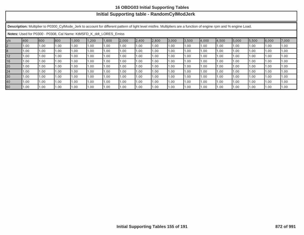
Initial Supporting table - RandomCylModJerkOBD GROUP:OBD GROUP: G TESTTEST GROUP: GG ---BIN4, FED---BIN4EMISSIONS STDS: Bin 4
Description: Multiplier to P0300_CylMode_Jerk to account for different pattern of light level misfire. Multipliers are a function of engine rpm and % engine Load.
Notes: Used for P0300 - P0308, Cal Name: KtMSFD_K_ddt_LORES_Emiss
y/x 400 600 800 1,000 1,200 1,600 2,000 2,400 2,800 3,000 3,500 4,000 4,500 5,000 5,500 6,000 7,000
2 1.00 1.00 1.00 1.00 1.00 1.00 1.00 1.00 1.00 1.00 1.00 1.00 1.00 1.00 1.00 1.00 1.00
8 1.00 1.00 1.00 1.00 1.00 1.00 1.00 1.00 1.00 1.00 1.00 1.00 1.00 1.00 1.00 1.00 1.00
12 1.00 1.00 1.00 1.00 1.00 1.00 1.00 1.00 1.00 1.00 1.00 1.00 1.00 1.00 1.00 1.00 1.00
16 1.00 1.00 1.00 1.00 1.00 1.00 1.00 1.00 1.00 1.00 1.00 1.00 1.00 1.00 1.00 1.00 1.00
20 1.00 1.00 1.00 1.00 1.00 1.00 1.00 1.00 1.00 1.00 1.00 1.00 1.00 1.00 1.00 1.00 1.00
24 1.00 1.00 1.00 1.00 1.00 1.00 1.00 1.00 1.00 1.00 1.00 1.00 1.00 1.00 1.00 1.00 1.00
30 1.00 1.00 1.00 1.00 1.00 1.00 1.00 1.00 1.00 1.00 1.00 1.00 1.00 1.00 1.00 1.00 1.00
40 1.00 1.00 1.00 1.00 1.00 1.00 1.00 1.00 1.00 1.00 1.00 1.00 1.00 1.00 1.00 1.00 1.00
60 1.00 1.00 1.00 1.00 1.00 1.00 1.00 1.00 1.00 1.00 1.00 1.00 1.00 1.00 1.00 1.00 1.00
650
16 OBDG03 Initial Supporting Tables
Initial Supporting Tables 155 of 191 872 of 991

Initial Supporting table - RandomRevModDeclOBD GROUP:OBD GROUP: TESTTEST GROUP: G IN4, FED---BIN4EMISSIONS STDS: Bin 4
Description: Mulitplier to P0300_RevMode_Decel to account for different pattern of light level misfire. Multipliers are a function of engine rpm and % engine Load.
Notes: Used for P0300 - P0308, Cal Name: KtMSFD_K_RevModeEmiss
y/x 3,000 3,500 4,000 4,500 5,000 5,500 6,000 7,000 8,000
2 1.00 1.00 1.00 1.00 1.00 1.00 1.00 1.00 1.00
8 1.00 1.00 1.00 1.00 1.00 1.00 1.00 1.00 1.00
12 1.00 1.00 1.00 1.00 1.00 1.00 1.00 1.00 1.00
16 1.00 1.00 1.00 1.00 1.00 1.00 1.00 1.00 1.00
20 1.00 1.00 1.00 1.00 1.00 1.00 1.00 1.00 1.00
24 1.00 1.00 1.00 1.00 1.00 1.00 1.00 1.00 1.00
30 1.00 1.00 1.00 1.00 1.00 1.00 1.00 1.00 1.00
40 1.00 1.00 1.00 1.00 1.00 1.00 1.00 1.00 1.00
60 1.00 1.00 1.00 1.00 1.00 1.00 1.00 1.00 1.00
651
16 OBDG03 Initial Supporting Tables
Initial Supporting Tables 156 of 191 873 of 991

Initial Supporting table - RepetSnapDecayAdjstOBD GROUP:OBD GROUP: TESTTEST GROUP: G IN4, FED---BIN4EMISSIONS STDS: Bin 4
Description: If misfire is present in consecutive engine cycles, this multiplier is applied to the misfire jerk threshold and compared to a crankshaft snap value after the misfire has takenplace.. Table lookup as a function of engine rpm.
Notes: Used for P0300 - P0308, Cal Name:KtMSFD_K_dddt_PostCylCnscMsfr
y/x 1,000 1,400 1,800 2,200 2,600 3,000 4,000 5,000 6,000
1 4.50 4.50 4.75 6.50 6.50 6.20 5.50 5.50 5.50
652
16 OBDG03 Initial Supporting Tables
Initial Supporting Tables 157 of 191 874 of 991

Initial Supporting table - RevMode_DecelOBD GROUP:OBD GROUP: TESTTEST GROUP: GG --BIN4, FED---BIN4EMISSIONS STDS: Bin 4
Description: Crankshaft decel threshold. Thresholds are a function of rpm and % engine Load.
Notes: Used for P0300-P0308. Cal Name: KtMISF_RevolutionMode
y/x 1,100 1,200 1,400 1,600 1,800 2,000 2,200 2,400 2,600 2,800 3,000 3,500 4,000 4,500 5,000 5,500 6,000 6,500 7,0003 32,767 32,767 32,767 32,767 32,767 32,767 32,767 32,767 32,767 32,767 32,767 32,767 32,767 32,767 32,767 32,767 32,767 32,767 32,7676 32,767 32,767 32,767 32,767 32,767 32,767 32,767 32,767 32,767 32,767 32,767 32,767 32,767 32,767 32,767 32,767 32,767 32,767 32,7678 32,767 32,767 32,767 32,767 32,767 32,767 32,767 32,767 32,767 32,767 32,767 32,767 32,767 32,767 32,767 32,767 32,767 32,767 32,76710 32,767 32,767 32,767 32,767 32,767 32,767 32,767 32,767 32,767 32,767 32,767 32,767 32,767 32,767 32,767 32,767 32,767 32,767 32,76712 32,767 32,767 32,767 32,767 32,767 32,767 32,767 32,767 32,767 32,767 32,767 32,767 32,767 32,767 32,767 32,767 32,767 32,767 32,76714 32,767 32,767 32,767 32,767 32,767 32,767 32,767 32,767 32,767 32,767 32,767 32,767 32,767 32,767 32,767 32,767 32,767 32,767 32,76716 32,767 32,767 32,767 32,767 32,767 32,767 32,767 32,767 32,767 32,767 32,767 32,767 32,767 32,767 32,767 32,767 32,767 32,767 32,76718 32,767 32,767 32,767 32,767 32,767 32,767 32,767 32,767 32,767 32,767 32,767 32,767 32,767 32,767 32,767 32,767 32,767 32,767 32,76720 32,767 32,767 32,767 32,767 32,767 32,767 32,767 32,767 32,767 32,767 32,767 32,767 32,767 32,767 32,767 32,767 32,767 32,767 32,76722 32,767 32,767 32,767 32,767 32,767 32,767 32,767 32,767 32,767 32,767 32,767 32,767 32,767 32,767 32,767 32,767 32,767 32,767 32,76724 32,767 32,767 32,767 32,767 32,767 32,767 32,767 32,767 32,767 32,767 32,767 32,767 32,767 32,767 32,767 32,767 32,767 32,767 32,76726 32,767 32,767 32,767 32,767 32,767 32,767 32,767 32,767 32,767 32,767 32,767 32,767 32,767 32,767 32,767 32,767 32,767 32,767 32,76730 32,767 32,767 32,767 32,767 32,767 32,767 32,767 32,767 32,767 32,767 32,767 32,767 32,767 32,767 32,767 32,767 32,767 32,767 32,76740 32,767 32,767 32,767 32,767 32,767 32,767 32,767 32,767 32,767 32,767 32,767 32,767 32,767 32,767 32,767 32,767 32,767 32,767 32,76760 32,767 32,767 32,767 32,767 32,767 32,767 32,767 32,767 32,767 32,767 32,767 32,767 32,767 32,767 32,767 32,767 32,767 32,767 32,76778 32,767 32,767 32,767 32,767 32,767 32,767 32,767 32,767 32,767 32,767 32,767 32,767 32,767 32,767 32,767 32,767 32,767 32,767 32,76797 32,767 32,767 32,767 32,767 32,767 32,767 32,767 32,767 32,767 32,767 32,767 32,767 32,767 32,767 32,767 32,767 32,767 32,767 32,767
653
16 OBDG03 Initial Supporting Tables
Initial Supporting Tables 158 of 191 875 of 991
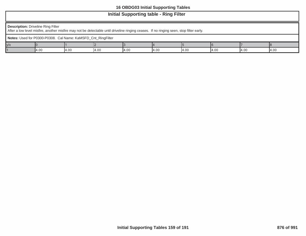
Initial Supporting table - Ring FilterTESTTEST GROUP: G -BIN4, FED---BIN4EMISSIONS STDS: Bin 4
Description: Driveline Ring FilterAfter a low level misfire, another misfire may not be detectable until driveline ringing ceases. If no ringing seen, stop filter early.
Notes: Used for P0300-P0308. Cal Name: KaMSFD_Cnt_RingFilter
y/x 0 1 2 3 4 5 6 7 8
1 4.00 4.00 4.00 4.00 4.00 4.00 4.00 4.00 4.00
654
16 OBDG03 Initial Supporting Tables
Initial Supporting Tables 159 of 191 876 of 991

Initial Supporting table - SCD_DecelOBD GROUP:OBD GROUP: TESTTEST GROUP: G --BIN4, FED---BIN4EMISSIONS STDS: Bin 4
Description: Crankshaft decel threshold. SCD mode uses smaller windows near TDC. Thresholds are a function of rpm and % engine Load.
Notes: Used for P0300-P0308. Cal Name: KtMISF_dt_SCD_OffIdleMode
y/x 400 500 600 700 800 900 1,000 1,100 1,200 1,400 1,600 1,800 2,0003 32,767 32,767 32,767 32,767 32,767 32,767 32,767 32,767 32,767 32,767 32,767 32,767 32,7676 32,767 32,767 32,767 32,767 32,767 32,767 32,767 32,767 32,767 32,767 32,767 32,767 32,7678 32,767 32,767 32,767 32,767 32,767 32,767 32,767 32,767 32,767 32,767 32,767 32,767 32,76710 32,767 32,767 32,767 32,767 32,767 32,767 32,767 32,767 32,767 32,767 32,767 32,767 32,76712 32,767 32,767 32,767 32,767 32,767 32,767 32,767 32,767 32,767 32,767 32,767 32,767 32,76714 32,767 32,767 32,767 32,767 32,767 32,767 32,767 32,767 32,767 32,767 32,767 32,767 32,76716 32,767 32,767 32,767 32,767 32,767 32,767 32,767 32,767 32,767 32,767 32,767 32,767 32,76718 32,767 32,767 32,767 32,767 32,767 32,767 32,767 32,767 32,767 32,767 32,767 32,767 32,76720 32,767 32,767 32,767 32,767 32,767 32,767 32,767 32,767 32,767 32,767 32,767 32,767 32,76722 32,767 32,767 32,767 32,767 32,767 32,767 32,767 32,767 32,767 32,767 32,767 32,767 32,76724 32,767 32,767 32,767 32,767 32,767 32,767 32,767 32,767 32,767 32,767 32,767 32,767 32,76726 32,767 32,767 32,767 32,767 32,767 32,767 32,767 32,767 32,767 32,767 32,767 32,767 32,76730 32,767 32,767 32,767 32,767 32,767 32,767 32,767 32,767 32,767 32,767 32,767 32,767 32,76740 32,767 32,767 32,767 32,767 32,767 32,767 32,767 32,767 32,767 32,767 32,767 32,767 32,76760 32,767 32,767 32,767 32,767 32,767 32,767 32,767 32,767 32,767 32,767 32,767 32,767 32,76778 32,767 32,767 32,767 32,767 32,767 32,767 32,767 32,767 32,767 32,767 32,767 32,767 32,76797 32,767 32,767 32,767 32,767 32,767 32,767 32,767 32,767 32,767 32,767 32,767 32,767 32,767
655
16 OBDG03 Initial Supporting Tables
Initial Supporting Tables 160 of 191 877 of 991

Initial Supporting table - SCD_JerkOBD GROUP:OBD GROUP: GG TESTTEST GROUP: G L---BIN4, FED---BIN4EMISSIONS STDS: Bin 4
Description: Crankshaft jerk threshold. SCD mode uses smaller windows near TDC. Thresholds are a function of rpm and % engine Load.
Notes: Used for P0300-P0308. Cal Name: KtMISF_ddt_SCD_OffIdleMode
y/x 400 500 600 700 800 900 1,000 1,100 1,200 1,400 1,600 1,800 2,0003 32,767 32,767 32,767 32,767 32,767 32,767 32,767 32,767 32,767 32,767 32,767 32,767 32,7676 32,767 32,767 32,767 32,767 32,767 32,767 32,767 32,767 32,767 32,767 32,767 32,767 32,7678 32,767 32,767 32,767 32,767 32,767 32,767 32,767 32,767 32,767 32,767 32,767 32,767 32,76710 32,767 32,767 32,767 32,767 32,767 32,767 32,767 32,767 32,767 32,767 32,767 32,767 32,76712 32,767 32,767 32,767 32,767 32,767 32,767 32,767 32,767 32,767 32,767 32,767 32,767 32,76714 32,767 32,767 32,767 32,767 32,767 32,767 32,767 32,767 32,767 32,767 32,767 32,767 32,76716 32,767 32,767 32,767 32,767 32,767 32,767 32,767 32,767 32,767 32,767 32,767 32,767 32,76718 32,767 32,767 32,767 32,767 32,767 32,767 32,767 32,767 32,767 32,767 32,767 32,767 32,76720 32,767 32,767 32,767 32,767 32,767 32,767 32,767 32,767 32,767 32,767 32,767 32,767 32,76722 32,767 32,767 32,767 32,767 32,767 32,767 32,767 32,767 32,767 32,767 32,767 32,767 32,76724 32,767 32,767 32,767 32,767 32,767 32,767 32,767 32,767 32,767 32,767 32,767 32,767 32,76726 32,767 32,767 32,767 32,767 32,767 32,767 32,767 32,767 32,767 32,767 32,767 32,767 32,76730 32,767 32,767 32,767 32,767 32,767 32,767 32,767 32,767 32,767 32,767 32,767 32,767 32,76740 32,767 32,767 32,767 32,767 32,767 32,767 32,767 32,767 32,767 32,767 32,767 32,767 32,76760 32,767 32,767 32,767 32,767 32,767 32,767 32,767 32,767 32,767 32,767 32,767 32,767 32,76778 32,767 32,767 32,767 32,767 32,767 32,767 32,767 32,767 32,767 32,767 32,767 32,767 32,76797 32,767 32,767 32,767 32,767 32,767 32,767 32,767 32,767 32,767 32,767 32,767 32,767 32,767
656
16 OBDG03 Initial Supporting Tables
Initial Supporting Tables 161 of 191 878 of 991

Initial Supporting table - SnapDecayAfterMisfireOBD GROUP:OBD GROUP: TESTTEST GROUP: G ---BIN4, FED---BIN4EMISSIONS STDS: Bin 4
Description: multiplier times the ddt_jerk value used used to detect misfire at that speed and load to see if size of disturbance has died down as expected of real misfire. Table lookup asa function of engine rpm and trans gear ratio.
Notes: Used for P0300 - P0308, Cal Name: KtMSFD_K_dddt_PostCylAft
y/x 1,000 1,400 1,800 2,200 2,600 3,000 4,000 5,000 6,0000 2.00 2.50 3.00 4.00 4.00 3.60 3.00 3.00 3.001 2.00 2.50 3.00 4.00 4.00 3.60 3.00 3.00 3.001 2.00 2.50 2.80 2.20 2.50 3.60 2.70 3.00 3.001 2.00 2.50 2.70 2.00 1.50 1.75 2.30 3.00 3.002 2.00 2.50 2.60 1.90 1.50 1.50 2.00 2.50 3.003 1.80 2.30 2.00 1.60 1.50 1.50 2.00 2.50 2.005 1.80 2.20 2.50 1.80 3.00 3.00 2.80 2.60 2.256 1.50 2.00 2.50 3.00 3.00 3.00 3.00 3.00 3.008 1.50 2.00 2.50 3.00 3.00 3.00 3.00 3.00 3.00
657
16 OBDG03 Initial Supporting Tables
Initial Supporting Tables 162 of 191 879 of 991

Initial Supporting table - TOSSRoughRoadThresOBD GROUP:OBD GROUP: TESTTEST GROUP: G L---BIN4, FED---BIN4EMISSIONS STDS: Bin 4
Description: Only used if Rough Road source = TOSS: dispersion value on Transmission Output Speed Sensor above which rough road is indicated present
Notes: Used for P0300-P0308. Cal Name: KtRRDI_a_RoughRoadThresh
y/x 600 800 1,000 1,200 1,400 1,600 1,800 2,000 2,200 2,400 2,600 2,800 3,000 3,500 4,000 4,500 5,000 5,500 6,000100 1.0 1.0 1.0 1.0 1.0 1.0 1.0 1.0 1.0 1.0 1.0 1.0 1.0 1.0 1.0 1.0 1.0 1.0 1.0200 1.0 1.0 1.0 1.0 1.0 1.0 1.0 1.0 1.0 1.0 1.0 1.0 1.0 1.0 1.0 1.0 1.0 1.0 1.0300 1.0 1.0 1.0 1.0 1.0 1.0 1.0 1.0 1.0 1.0 1.0 1.0 1.0 1.0 1.0 1.0 1.0 1.0 1.0400 1.0 1.0 1.0 1.0 1.0 1.0 1.0 1.0 1.0 1.0 1.0 1.0 1.0 1.0 1.0 1.0 1.0 1.0 1.0500 1.0 1.0 1.0 1.0 1.0 1.0 1.0 1.0 1.0 1.0 1.0 1.0 1.0 1.0 1.0 1.0 1.0 1.0 1.0600 1.0 1.0 1.0 1.0 1.0 1.0 1.0 1.0 1.0 1.0 1.0 1.0 1.0 1.0 1.0 1.0 1.0 1.0 1.0700 1.0 1.0 1.0 1.0 1.0 1.0 1.0 1.0 1.0 1.0 1.0 1.0 1.0 1.0 1.0 1.0 1.0 1.0 1.0800 1.0 1.0 1.0 1.0 1.0 1.0 1.0 1.0 1.0 1.0 1.0 1.0 1.0 1.0 1.0 1.0 1.0 1.0 1.0900 1.0 1.0 1.0 1.0 1.0 1.0 1.0 1.0 1.0 1.0 1.0 1.0 1.0 1.0 1.0 1.0 1.0 1.0 1.01,000 1.0 1.0 1.0 1.0 1.0 1.0 1.0 1.0 1.0 1.0 1.0 1.0 1.0 1.0 1.0 1.0 1.0 1.0 1.01,100 1.0 1.0 1.0 1.0 1.0 1.0 1.0 1.0 1.0 1.0 1.0 1.0 1.0 1.0 1.0 1.0 1.0 1.0 1.01,200 1.0 1.0 1.0 1.0 1.0 1.0 1.0 1.0 1.0 1.0 1.0 1.0 1.0 1.0 1.0 1.0 1.0 1.0 1.01,300 1.0 1.0 1.0 1.0 1.0 1.0 1.0 1.0 1.0 1.0 1.0 1.0 1.0 1.0 1.0 1.0 1.0 1.0 1.01,400 1.0 1.0 1.0 1.0 1.0 1.0 1.0 1.0 1.0 1.0 1.0 1.0 1.0 1.0 1.0 1.0 1.0 1.0 1.0
658
16 OBDG03 Initial Supporting Tables
Initial Supporting Tables 163 of 191 880 of 991

Initial Supporting table - WSSRoughRoadThresOBD GROUP:OBD GROUP: TESTTEST GROUP: G E-BIN4, FED---BIN4EMISSIONS STDS: Bin 4
Description: Only used if Wheel speed from ABS is used. If difference between wheel speed readings is larger than this limit, rough road is present
Notes: Used for P0300-P0308. Cal Name: KtRRDI_a_WhlSpdRoughRoadLim
y/x 0 12 24 36 48 60 72 85 97 109 121 133 145 157 169 181 1931 1.00 1.00 1.00 1.00 1.00 1.00 1.00 1.00 1.00 1.00 1.00 1.00 1.00 1.00 1.00 1.00 1.00
659
16 OBDG03 Initial Supporting Tables
Initial Supporting Tables 164 of 191 881 of 991

Initial Supporting table - ZeroTorqueEngLoadOBD GROUP:OBD GROUP: TESTTEST GROUP: G BIN4, FED---BIN4EMISSIONS STDS: Bin 4
Description: %air load that represents Zero Brake torque along the Neutral rev line. The Zero torque threshold is adjusted for Baro via P0300_ZeroTorqueBaro
Notes: Used for P0300-P0308. Cal Name: KtMISF_ZeroTorqSpd
ZeroTorqueEngLoad - Part 1
y/x 400 500 600 700 800 900 1,000 1,100 1,200 1,400 1,600 1,800 2,00065 -0.40 -0.70 -0.90 -1.05 -1.18 -1.30 -1.40 -1.50 -1.60 -1.75 -1.85 -1.90 -1.9575 -0.40 -0.70 -0.90 -1.05 -1.18 -1.30 -1.40 -1.50 -1.60 -1.75 -1.85 -1.90 -1.9585 -0.40 -0.70 -0.90 -1.05 -1.18 -1.30 -1.40 -1.50 -1.60 -1.75 -1.85 -1.90 -1.9595 -0.40 -0.70 -0.90 -1.05 -1.18 -1.30 -1.40 -1.50 -1.60 -1.75 -1.85 -1.90 -1.95105 -0.40 -0.70 -0.90 -1.05 -1.18 -1.30 -1.40 -1.50 -1.60 -1.75 -1.85 -1.90 -1.95
ZeroTorqueEngLoad - Part 2
y/x 2,200 2,400 2,600 2,800 3,000 3,500 4,000 4,500 5,000 5,500 6,000 6,500 7,00065 -1.98 -2.00 -2.00 -2.00 -2.00 -0.75 0.50 1.75 3.00 4.25 5.50 6.75 8.0075 -1.98 -2.00 -2.00 -2.00 -2.00 -0.75 0.50 1.75 3.00 4.25 5.50 6.75 8.0085 -1.98 -2.00 -2.00 -2.00 -2.00 -0.75 0.50 1.75 3.00 4.25 5.50 6.75 8.0095 -1.98 -2.00 -2.00 -2.00 -2.00 -0.75 0.50 1.75 3.00 4.25 5.50 6.75 8.00105 -1.98 -2.00 -2.00 -2.00 -2.00 -0.75 0.50 1.75 3.00 4.25 5.50 6.75 8.00
660
16 OBDG03 Initial Supporting Tables
Initial Supporting Tables 165 of 191 882 of 991

Initial Supporting table - Closed Loop Enable Clarification - KaFCLP_U_SlphrIntglOfst_ThrshOBD GROUP:OBD GROUP: TESTTEST GROUP: G AL---BIN4, FED---BIN4EMISSIONS STDS: Bin 4
Description: Integral Offset voltage thresholds (bank and cell specific cals) used with KeFCLP_Pct_CatAccuSlphrPostDsbl to check for sulphur poisoning.
Notes: millivolts
y/x CiOXYR_O2_PostCat1 CiOXYR_O2_PostCat2CiFCLP_Decel 2,048 2,048
CiFCLP_Idle 2,048 2,048
CiFCLP_Cruise 2,048 2,048
CiFCLP_LightAccel 2,048 2,048
CiFCLP_HeavyAccel 2,048 2,048
661
16 OBDG03 Initial Supporting Tables
Initial Supporting Tables 166 of 191 883 of 991

Initial Supporting table - Closed Loop Enable Clarification - KcFCLP_Cnt_O2RdyCyclesThrshOBD GROUP:OBD GROUP: TESTTEST GROUP: G -BIN4, FED---BIN4EMISSIONS STDS: Bin 4
Description: Number of post catalyst oxygen sensor samples which must be outside not ready window before post oxygen sensor is READY.
Notes: Time (events * 12.5 milliseconds)
y/x 1
1 80
662
16 OBDG03 Initial Supporting Tables
Initial Supporting Tables 167 of 191 884 of 991

Initial Supporting table - Closed Loop Enable Clarification - KcFULC_O2_SensorReadyEventsOBD GROUP:OBD GROUP: TESTTEST GROUP: G NS STDS: CAL---BIN4, FED--- 4
Description: Number of times an oxygen sensor value must be in range before declaring it ready
Notes: Time (events * 12.5 milliseconds)
y/x 1
1 2
663
16 OBDG03 Initial Supporting Tables
Initial Supporting Tables 168 of 191 885 of 991

Initial Supporting table - Closed Loop Enable Clarification - KeFCLP_Pct_CatAccuSlphrPostDsblOBD GROUP:OBD GROUP: TESTTEST GROUP: G L---BIN4, FED---BIN4EMISSIONS STDS: Bin 4
Description: Sulphur percent threshold above which post integral learning is disabled if the threshold criteria KaFCLP_U_SlphrIntglOfst_Thrsh is also met.
Notes: Percent
y/x 1
1 255
664
16 OBDG03 Initial Supporting Tables
Initial Supporting Tables 169 of 191 886 of 991
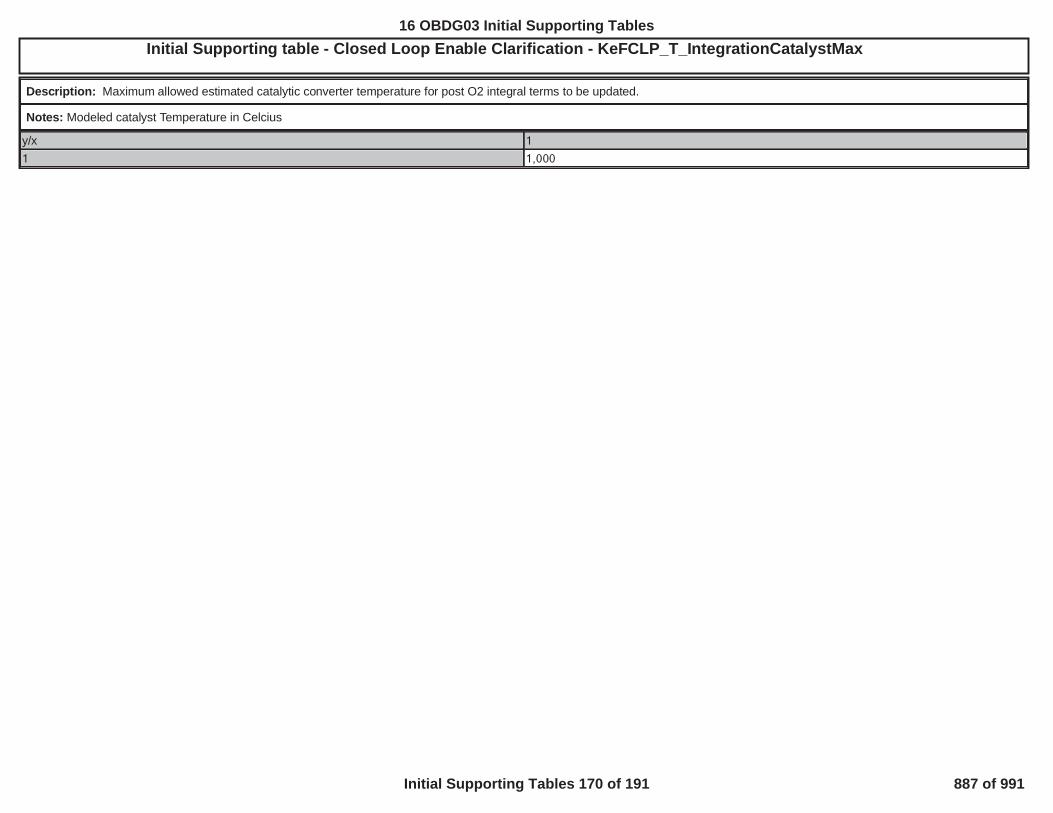
Initial Supporting table - Closed Loop Enable Clarification - KeFCLP_T_IntegrationCatalystMaxOBD GROUP:OBD GROUP: TESTTEST GROUP: G E-BIN4, FED---BIN4EMISSIONS STDS: Bin 4
Description: Maximum allowed estimated catalytic converter temperature for post O2 integral terms to be updated.
Notes: Modeled catalyst Temperature in Celcius
y/x 1
1 1,000
665
16 OBDG03 Initial Supporting Tables
Initial Supporting Tables 170 of 191 887 of 991

Initial Supporting table - Closed Loop Enable Clarification - KeFCLP_T_IntegrationCatalystMinOBD GROUP:OBD GROUP: TESTTEST GROUP: GG --BIN4, FED---BIN4EMISSIONS STDS: Bin 4
Description: Minimum allowed estimated catalytic converter temperature to begin using post O2 integration correction terms. Converter temperature must remain above this threshold toramp-in the post O2 integration adjustments. Once the ramp-in has started, a converter temperature below this threshold will freeze the ramp-in multiplier. Post O2 integration will not beallowed below this converter temperature
Notes: Modeled catalyst Temperature in Celcius
y/x 1
1 425
666
16 OBDG03 Initial Supporting Tables
Initial Supporting Tables 171 of 191 888 of 991

Initial Supporting table - Closed Loop Enable Clarification - KeWRSC_T_HtrCntrlCLIN4, FED---BIN4EMISSIONS STDS: Bin 4
Description: WRAF heater temperature enabling threshold for transition from Open Loop to Closed Loop
Notes: Degrees Celcius
y/x 1
1 628
667
16 OBDG03 Initial Supporting Tables
Initial Supporting Tables 172 of 191 889 of 991

Initial Supporting table - Closed Loop Enable Clarification - KeWRSI_T_PumpCurrentEnableOBD GROUP:OBD GROUP: G TESTTEST GROUP: G -BIN4, FED---BIN4EMISSIONS STDS: Bin 4
Description: WRAF heater temperature threshold for enabling the sensor pump current
Notes: Degrees Celcius
y/x 1
1 628
668
16 OBDG03 Initial Supporting Tables
Initial Supporting Tables 173 of 191 890 of 991

Initial Supporting table - Closed Loop Enable Clarification - KfFCLL_T_AdaptiveHiCoolantOBD GROUP:OBD GROUP: TESTTEST GROUP: G IN4, FED---BIN4EMISSIONS STDS: Bin 4
Description: LTM learning is inhibited if the engine coolant temperature is above this calibration.
Notes: Degrees Celcius
y/x 1
1 255
669
16 OBDG03 Initial Supporting Tables
Initial Supporting Tables 174 of 191 891 of 991
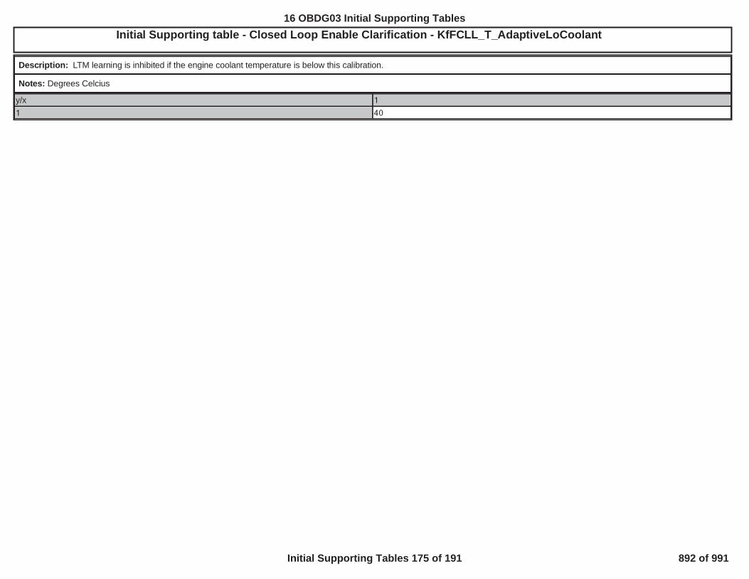
Initial Supporting table - Closed Loop Enable Clarification - KfFCLL_T_AdaptiveLoCoolantOBD GROUP:OBD GROUP: TESTTEST GROUP: G IN4, FED---BIN4EMISSIONS STDS: Bin 4
Description: LTM learning is inhibited if the engine coolant temperature is below this calibration.
Notes: Degrees Celcius
y/x 1
1 40
670
16 OBDG03 Initial Supporting Tables
Initial Supporting Tables 175 of 191 892 of 991

Initial Supporting table - Closed Loop Enable Clarification - KfFCLP_U_O2ReadyThrshLoEIN4, FED---BIN4EMISSIONS STDS: Bin 4
Description: Lower threshold defining not ready window for post oxygen sensor voltage.
Notes: Voltage in millivolts
y/x 1
1 1,100
671
16 OBDG03 Initial Supporting Tables
Initial Supporting Tables 176 of 191 893 of 991

Initial Supporting table - Closed Loop Enable Clarification - KtFCLL_p_AdaptiveLowMAP_LimitOBD GROUP:OBD GROUP: TESTTEST GROUP: GGMXT02 --BIN4, FED---BIN4EMISSIONS STDS: Bin 4
Description: KtFCLL_p_AdaptiveLowMAP_Limit
Notes: MAP in KPa
y/x 65 70 75 80 85 90 95 100 105
1 16.0 16.0 16.0 16.0 16.0 17.0 18.0 18.0 18.0
672
16 OBDG03 Initial Supporting Tables
Initial Supporting Tables 177 of 191 894 of 991

Initial Supporting table - Closed Loop Enable Clarification - KtFCLP_t_PostIntglDisableTimeOBD GROUP:OBD GROUP: TESTTEST GROUP: GG IN4, FED---BIN4EMISSIONS STDS: Bin 4
Description: Disable integral offset after engine start for this amount of time.
Notes: Time in seconds
y/x -40 -29 -18 -6 5 16 28 39 50 61 73 84 95 106 118 129 1401 100.0 100.0 100.0 100.0 100.0 100.0 100.0 100.0 100.0 80.0 60.0 50.0 50.0 50.0 50.0 50.0 50.0
673
16 OBDG03 Initial Supporting Tables
Initial Supporting Tables 178 of 191 895 of 991

Initial Supporting table - Closed Loop Enable Clarification - KtFCLP_t_PostIntglRampInTimeOBD GROUP:OBD GROUP: G TESTTEST GROUP: G IN4, FED---BIN4EMISSIONS STDS: Bin 4
Description: Time required to ramp integral offset to desired value.
Notes: Time in seconds
y/x -40 -29 -18 -6 5 16 28 39 50 61 73 84 95 106 118 129 1401 50.0 50.0 50.0 50.0 50.0 50.0 50.0 50.0 40.0 30.0 20.0 10.0 10.0 10.0 10.0 10.0 10.0
674
16 OBDG03 Initial Supporting Tables
Initial Supporting Tables 179 of 191 896 of 991

Initial Supporting table - Closed Loop Enable Clarification - KtFSTA_t_ClosedLoopAutostartOBD GROUP:OBD GROUP: TESTTEST GROUP: G ---BIN4, FED---BIN4EMISSIONS STDS: Bin 4
Description: Engine run time following an autostart, as a function of begin run coolant, which must be exceeded to enable CLOSED LOOP.
Notes: Time in seconds: Hybrid use Only
y/x -40 -28 -16 -4 8 20 32 44 56 68 80 92 104 116 128 140 152
1 300.0 300.0 230.0 90.0 80.0 32.0 32.0 32.0 0.0 0.0 0.0 0.0 0.0 0.0 0.0 0.0 0.0
675
16 OBDG03 Initial Supporting Tables
Initial Supporting Tables 180 of 191 897 of 991

Initial Supporting table - Closed Loop Enable Clarification - KtFSTA_t_ClosedLoopTimeOBD GROUP: D2UB LTGOBD GROUP: GGMXOBDG03 --BIN4, FED---BIN4EMISSIONS STDS: Bin 4
Description: Engine run time, as a function of startup coolant temperature, which must be exceeded to enable CLOSED LOOP.
Notes: Time in seconds
y/x -40 -28 -16 -4 8 20 32 44 56 68 80 92 104 116 128 140 152
1 300.0 300.0 230.0 90.0 80.0 32.0 32.0 32.0 32.0 32.0 0.0 0.0 0.0 0.0 0.0 0.0 0.0
676
16 OBDG03 Initial Supporting Tables
Initial Supporting Tables 181 of 191 898 of 991

Initial Supporting table - P050D_P1400_CatalystLightOffExtendedEngineRunTimeExitO ---BIN4, FED---BIN4EMISSIONS STDS: Bin 4
Description: Exit Catalyst Warm-up mode if Engine Run Time is greater than this value. This table is based on percent ethanol (x-axis) and catmon’s NormRatio_EWMA value (y-axis).The NormRatio_EWMA value determines the state of the catalyst. Typically, NormRatio_EWMA values below 0.35 (0 is bad and 1 is good) represent catalysts that have degraded. Theemission performance of these degraded catalysts can be improved by extending catalyst light off of GetE85R_Pct_FFS_CompAtEngFloat.
Notes: KtCSEC_t_ExtendedEngineExit. Used for both P050D and P1400.
y/x 0 25 50 75 100
0.000 45 45 45 45 45
0.125 45 45 45 45 45
0.250 45 45 45 45 45
0.375 45 45 45 45 45
0.500 22 22 28 33 33
0.625 22 22 28 33 33
0.750 22 22 28 33 33
0.875 22 22 28 33 33
1.000 22 22 28 33 33
677
16 OBDG03 Initial Supporting Tables
Initial Supporting Tables 182 of 191 899 of 991

Initial Supporting table - P1400_ColdStartDiagnosticDelayBasedOnEngineRunTimeOBD GR L---BIN4, FED---BIN4EMISSIONS STDS: Bin 4
Description: Quality weight-based on engine run time. This allows adjustment of the weighting factors at various engine run times in order to prevent the updating of the cumulative qualitytimer or to change the value of the average qualified residual energy calculation to prevent false Fails of the diagnostic under circumstances inappropriate to update the calculation of theaverage qualified residual value.
Notes: KtCSED_K_TimeWght - This is used for P1400.
y/x 0 3 3 4 5 10 15 20 30
1 0 0 1 1 1 1 1 1 1
678
16 OBDG03 Initial Supporting Tables
Initial Supporting Tables 183 of 191 900 of 991

Initial Supporting table - P1400_ColdStartDiagnosticDelayBasedOnEngineRunTimeCalAxisOBD GROUP:OBD GROUP: TESTTEST GROUP: GG -BIN4, FED---BIN4EMISSIONS STDS: Bin 4
Description: This is the x-axis for the KtCSED_K_TimeWght calibration table. Refer to the description for KtCSED_K_TimeWght for details.
Notes: KnCSED_t_TimeWght - This is used for P1400.
y/x 1 2 3 4 5 6 7 8 91 0 3 3 4 5 10 15 20 30
679
16 OBDG03 Initial Supporting Tables
Initial Supporting Tables 184 of 191 901 of 991

Initial Supporting table - P1400_EngineSpeedResidual_TableOBD GROUP:OBD GROUP: TESTTEST GROUP: G ---BIN4, FED---BIN4EMISSIONS STDS: Bin 4
Description: This 1x17 table of engine exhaust flow values is used to calculate both the desired and the actual engine exhaust flow based on desired and actual engine speed. The desiredengine exhaust flow is gathered from the desired engine speed (VeSPDR_n_EngDsrd). The value used for the actual engine exhaust flow is based on the actual engine RPM value.
Notes: KtCSED_dm_Exh - This is used for P1400
y/x 500 975 990 1,000 1,020 1,050 1,100 1,150 1,175 1,200 1,250 1,280 1,290 1,300 1,400 1,900 2,500
1 7 7 7 10 11 11 11 11 11 11 11 11 14 15 15 15 15
680
16 OBDG03 Initial Supporting Tables
Initial Supporting Tables 185 of 191 902 of 991

Initial Supporting table - P1400_SparkResidual_TableOBD GROUP:OBD GROUP: TESTTEST GROUP: G E-BIN4, FED---BIN4EMISSIONS STDS: Bin 4
Description: Predicted engine-out energy potential based on either the desired cold start spark advance value or the actual spark advance value. ExhEngyPerUnitMass calibration isused to calculate both desired exhaust energy and actual energy. The desired and actual exhaust energy per unit mass values areused in part to calculate the desired exhaust energy per unit time and actual exhaust energy per unit time. Both desired and actual go into the residual exhaust
energy per unit time calculation.
Notes: KtCSED_E_ExhEngyPerUnitMass
y/x -18 -8 -6 -4 0 4 6 10 20
1 1.25 1.25 1.25 1.19 1.19 1.06 0.63 0.63 0.63
681
16 OBDG03 Initial Supporting Tables
Initial Supporting Tables 186 of 191 903 of 991

Initial Supporting table - DFCO_CoolEnblHi_TempOBD GROUP:OBD GROUP: TESTTEST GROUP: GG -BIN4, FED---BIN4EMISSIONS STDS: Bin 4
Description:
Notes:
y/x -40 0 25
1 45.0 45.0 45.0
682
16 OBDG03 Initial Supporting Tables
Initial Supporting Tables 187 of 191 904 of 991

Initial Supporting table - DFCO_DelayAfterStart_TimeOBD GROUP:OBD GROUP: TESTTEST GROUP: GG BIN4, FED---BIN4EMISSIONS STDS: Bin 4
Description:
Notes:
y/x -30 -10 20 60 90
1 10.0 7.5 5.0 5.0 5.0
683
16 OBDG03 Initial Supporting Tables
Initial Supporting Tables 188 of 191 905 of 991

Initial Supporting table - DFCO_DsblLo_Vehicle_SpeedOBD GROUP:OBD GROUP: TESTTEST GROUP: G EL---BIN4, FED---BIN4EMISSIONS STDS: Bin 4
Description:
Notes:
y/x CeTCOR_e_NonEcoMode CeTCOR_e_EcoModeCeTGRR_e_TransGr1 20 20
CeTGRR_e_TransGr2 0 0
CeTGRR_e_TransGr3 0 0
CeTGRR_e_TransGr4 0 0
CeTGRR_e_TransGr5 0 0
CeTGRR_e_TransGr6 0 0
CeTGRR_e_TransGrEVT1 0 0
CeTGRR_e_TransGrEVT2 0 0
CeTGRR_e_TransGrNeut 0 0
CeTGRR_e_TransGrRvrs 0 0
CeTGRR_e_TransGrPark 0 0
CeTGRR_e_TransGr7 0 0
CeTGRR_e_TransGr8 0 0
684
16 OBDG03 Initial Supporting Tables
Initial Supporting Tables 189 of 191 906 of 991

Initial Supporting table - DFCO_EnblHi_Vehicle_SpeedOBD GROUP:OBD GROUP: G TESTTEST GROUP: G L---BIN4, FED---BIN4EMISSIONS STDS: Bin 4
Description:
Notes:
y/x CeTCOR_e_NonEcoMode CeTCOR_e_EcoModeCeTGRR_e_TransGr1 20.0 20.0
CeTGRR_e_TransGr2 20.0 20.0
CeTGRR_e_TransGr3 26.0 26.0
CeTGRR_e_TransGr4 20.0 20.0
CeTGRR_e_TransGr5 0.0 0.0
CeTGRR_e_TransGr6 0.0 0.0
CeTGRR_e_TransGrEVT1 0.0 0.0
CeTGRR_e_TransGrEVT2 0.0 0.0
CeTGRR_e_TransGrNeut 0.0 0.0
CeTGRR_e_TransGrRvrs 512.0 512.0
CeTGRR_e_TransGrPark 0.0 0.0
CeTGRR_e_TransGr7 0.0 0.0
CeTGRR_e_TransGr8 0.0 0.0
685
16 OBDG03 Initial Supporting Tables
Initial Supporting Tables 190 of 191 907 of 991

Initial Supporting table - DFCO_EngSpdEnblOfstOBD GROUP:OBD GROUP: TESTTEST GROUP: G ---BIN4, FED---BIN4EMISSIONS STDS: Bin 4
Description:
Notes:
y/x -1,750 -1,500 -1,250 -1,000 -750 -500 -300 -100 0
1 300 233 167 100 0 0 0 0 0
686
16 OBDG03 Initial Supporting Tables
Initial Supporting Tables 191 of 191 908 of 991

Initial Supporting table - P0411 Phase 1 Amb Temp Test Weight Factorn 4
Description: SAI Flow (Phase 1) Test ambient temperature weight factor.
Notes: DTC: P0411; Cal: KtAIRD_K_SAI_TstTempDsbld; Axis is Ambient (IAT) Temp (C).
y/x -30 -20 -10 0 10 20 30 40 50
1 0.0 0.0 0.0 0.5 1.0 1.0 1.0 1.0 1.0
41
16 OBDG03 Unique Supporting Tables
Unique Supporting Tables 1 of 38 909 of 991

Initial Supporting table - P0411 Phase 1 Baro Test Weight FactorP1427 EDS: Bin 4
Description: SAI Flow (Phase 1) Test baro weight factor.
Notes: DTC: P0411; Cal: KtAIRD_K_SAI_TstBaroDsbld; Axis is atmospheric pressure (kPa)
y/x 40 50 60 70 80 90 100 110 120
1 0.0 0.0 0.5 1.0 1.0 1.0 1.0 1.0 0.0
42
16 OBDG03 Unique Supporting Tables
Unique Supporting Tables 2 of 38 910 of 991
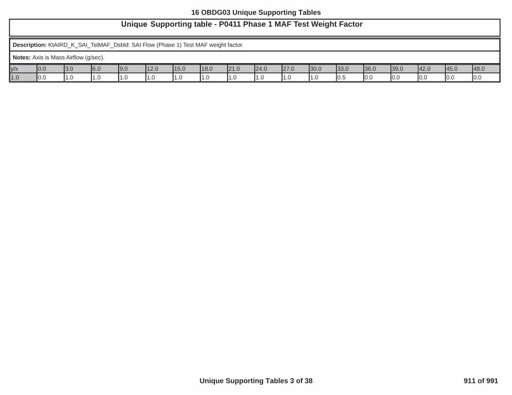
Initial Supporting table - P0411 Phase 1 MAF Test Weight FactorMXOBDG03P: 0700KPJP1427 4
Description: KtAIRD_K_SAI_TstMAF_Dsbld: SAI Flow (Phase 1) Test MAF weight factor.
Notes: Axis is Mass Airflow (g/sec).
y/x 0.0 3.0 6.0 9.0 12.0 15.0 18.0 21.0 24.0 27.0 30.0 33.0 36.0 39.0 42.0 45.0 48.01.0 0.0 1.0 1.0 1.0 1.0 1.0 1.0 1.0 1.0 1.0 1.0 0.5 0.0 0.0 0.0 0.0 0.0
43
16 OBDG03 Unique Supporting Tables
Unique Supporting Tables 3 of 38 911 of 991

Initial Supporting table - P0411 Phase 1 System Volt Test Weight FactorGMXOBDG03P: 0700KPJP1427 4
Description: SAI Flow (Phase 1) Test system voltage weight factor.
Notes: DTC: P0411; Cal: KtAIRD_K_SAI_TstVoltDsbld; Axis is system voltage (V).
y/x 5.0 6.0 7.0 8.0 9.0 10.0 11.0 12.0 13.0 14.0 15.0 16.0 17.0 18.0 19.0 20.0 21.01.0 0.0 0.0 0.0 0.0 0.0 0.5 0.8 1.0 1.0 1.0 1.0 1.0 0.8 0.5 0.5 0.5 0.5
44
16 OBDG03 Unique Supporting Tables
Unique Supporting Tables 4 of 38 912 of 991

Initial Supporting table - P0411 SL Threshold Bank 1 TableJP1427 4
Description: Bank 1 SAI Flow (Phase 1) Test Average String Length failure threshold versus MAF (g/sec).
Notes: DTCs: P0411; Cal: KtAIRD_dp_SAI_SL_ThrshBank1
y/x 0.0 3.0 6.0 9.0 12.0 15.0 18.0 21.0 24.0 27.0 30.0 33.0 36.0 39.0 42.0 45.0 48.01.0 20.0 20.0 20.0 20.0 20.0 20.0 20.0 20.0 20.0 20.0 20.0 20.0 20.0 20.0 20.0 20.0 20.0
45
16 OBDG03 Unique Supporting Tables
Unique Supporting Tables 5 of 38 913 of 991

Initial Supporting table - P2431_P2436 Baro Skewed Sensor Weight Factor4
Description: The AIR Pressure Sensor Test quality factor based on the distance traveled since the last unthrottled ambient pressure update.
Notes: DTCs: P2431 & P2436; Cal: KtAIRD_K_APPD_BaroQlty; P2436 is applicable on dual valve applications only. Axis is distance traveled from last Baro update in Km (1Km = 0.62Miles).
y/x 0.0 2.0 4.0 6.0 8.0 10.0 12.0 14.0 16.0 18.0 20.0 22.0 24.0 26.0 28.0 30.0 32.0
1.0 1.0 0.8 0.5 0.3 0.0 0.0 0.0 0.0 0.0 0.0 0.0 0.0 0.0 0.0 0.0 0.0 0.0
46
16 OBDG03 Unique Supporting Tables
Unique Supporting Tables 6 of 38 914 of 991

Initial Supporting table - P2440 Bank 1 Valve Pressure Error4
Description: Sensor 1 minimum average pressure error (kPa) threshold for the valve-shut (Phase 2) test .
Notes: DTCs: P2440; Cal: KaAIRD_p_VlvTstPresErrMin[CeAIRR_e_PresSnsrOne]; Axis is Conditional Test Weight Time in seconds.
y/x 0 1 2 3 4 5 6 7 8
1 -3.0 -3.0 -3.0 -3.0 -3.0 -3.0 -3.0 -3.0 -3.0
47
16 OBDG03 Unique Supporting Tables
Unique Supporting Tables 7 of 38 915 of 991

Initial Supporting table - P2440 Phase 2 Amb Temp Test Weight Factor4
Description: Ambient Temperature component of the conditional test weight for the valve-shut (Phase 2) test.
Notes: DTCs: P2440; Cal: KtAIRD_K_VlvTstTempDsbld; Axis is ambient temperature (IAT) in Deg C.
y/x -30 -20 -10 0 10 20 30 40 50
1 0.0 0.0 0.0 0.5 1.0 1.0 1.0 1.0 1.0
48
Unique16 OBDG03 Unique Supporting Tables
Unique Supporting Tables 8 of 38 916 of 991

Initial Supporting table - P2440 Phase 2 Baro Test Weight Factor4
Description: Ambient pressure component of the conditional test weight for the valve-shut (Phase 2) test .
Notes: DTCs: P2440; Cal: KtAIRD_K_VlvTstBaroDsbld; Axis is ambient pressure (kPa).
y/x 40 50 60 70 80 90 100 110 120
1 0.0 0.0 0.5 1.0 1.0 1.0 1.0 1.0 0.0
49
16 OBDG03 Unique Supporting Tables
Unique Supporting Tables 9 of 38 917 of 991

Initial Supporting table - P2440 Phase 2 MAF Test Weight Factor4
Description: Mass Airflow (MAF) component of the conditional test weight for the valve-shut (Phase 2) test.
Notes: DTCs: P2440; Cal: KtAIRD_K_VlvTstMAF_Dsbld; Axis is mass airflow (g/s).
y/x 0.0 3.0 6.0 9.0 12.0 15.0 18.0 21.0 24.0 27.0 30.0 33.0 36.0 39.0 42.0 45.0 48.01.0 0.0 1.0 1.0 1.0 1.0 1.0 1.0 1.0 1.0 1.0 1.0 0.5 0.0 0.0 0.0 0.0 0.0
50
16 OBDG03 Unique Supporting Tables
Unique Supporting Tables 10 of 38 918 of 991

Initial Supporting table - P2440 Phase 2 System Volt Test Weight Factor4
Description: System Voltage component of the conditional test weight for the valve-shut (Phase 2) test.
Notes: DTCs: P2440; Cal: KtAIRD_K_VlvTstVoltDsbld; Axis is system volts (V).
y/x 5.0 6.0 7.0 8.0 9.0 10.0 11.0 12.0 13.0 14.0 15.0 16.0 17.0 18.0 19.0 20.0 21.01.0 0.0 0.0 0.0 0.0 0.0 0.5 0.8 1.0 1.0 1.0 1.0 1.0 0.8 0.5 0.5 0.5 0.5
51
16 OBDG03 Unique Supporting Tables
Unique Supporting Tables 11 of 38 919 of 991

Initial Supporting table - P2444 Bank 1 Pump Pressure Error4
Description: Sensor 1 maximum average pressure error threshold for the pump-off (Phase 3) test.
Notes: DTCs: P2444; Cal: KaAIRD_p_PmpTstPresErrMax[CeAIRR_e_PresSnsrOne]; Axis is Conditional Test Weight Time in seconds.
y/x 0 1 2 3 4 5 6 7 8
1 2.0 2.0 2.0 2.0 2.0 2.0 2.0 2.0 2.0
52
16 OBDG03 Unique Supporting Tables
Unique Supporting Tables 12 of 38 920 of 991

Initial Supporting table - P1065_UCAP_Arm_Autostart_Thresh_Derating_Zero
Description: This is the minimum Cap voltage to arm an AutoStop-Start. When the charging diagnostic is enabled, and the Cap voltage is less than the table value a failure counter isincrementated. The axis of this table is capacitor state of health level (0 to 100%)
Notes:
y/x 0 13 25 38 50 63 75 88 1001 4.30 4.20 4.10 4.00 3.90 3.80 3.70 3.60 3.50
75
16 OBDG03 Unique Supporting Tables
Unique Supporting Tables 13 of 38 921 of 991
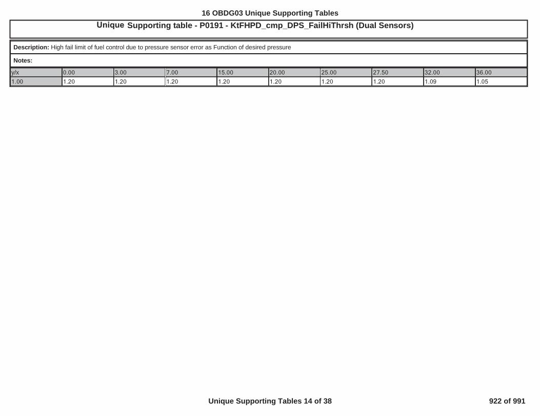
Initial Supporting table - P0191 - KtFHPD_cmp_DPS_FailHiThrsh (Dual Sensors)
Description: High fail limit of fuel control due to pressure sensor error as Function of desired pressure
Notes:
y/x 0.00 3.00 7.00 15.00 20.00 25.00 27.50 32.00 36.00
1.00 1.20 1.20 1.20 1.20 1.20 1.20 1.20 1.09 1.05
24
16 OBDG03 Unique Supporting Tables
Unique Supporting Tables 14 of 38 922 of 991

Initial Supporting table - P0191 - KtFHPD_cmp_DPS_FailLoThrsh (Dual sensors)4
Description: Low fail limit of fuel control due to pressure sensor error as Function of desired pressure
Notes:
y/x 0.00 3.00 7.00 15.00 20.00 25.00 27.50 32.00 36.00
1.00 0.75 0.75 0.75 0.75 0.79 0.82 0.86 0.92 0.95
25
4
16 OBDG03 Unique Supporting Tables
Unique Supporting Tables 15 of 38 923 of 991

Initial Supporting table - P0806 EngTorqueThreshold Table
Description: The diagnostic is inhibited if torque (NM) is less than this value. Prevents false fails in regions where false in-gear N/TOS ratios are possible due to low torque, where hightorque would otherwise cause slip and prevent a valid in-gear state.
Notes: DTCs: P0806; Calibration Name: KtMTCI_M_TorqueEnable; Axis label is Percent Clutch Pedal Position (%), where 0% = bottom of pedal travel. Calibration value units are torque(Newton-Meters).
y/x 0.00 6.25 12.50 18.75 25.00 31.25 37.50 43.75 50.00 56.25 62.50 68.75 75.00 81.25 87.50 93.75 100.001 10.0 13.8 17.8 21.5 25.3 29.3 33.0 0.0 0.0 0.0 0.0 0.0 0.0 0.0 0.0 0.0 0.0
26
16 OBDG03 Unique Supporting Tables
Unique Supporting Tables 16 of 38 924 of 991

Initial Supporting table - P0806 ResidualErrEnableHigh Table
Description: Represents the upper threshold of a deadband where the diagnostic will be inhibited to prevent false fails due to clutch slip that can falsely indicate a valid in-gear N/TOSratio. The lower threshold of the deadband is represented by the table "P0806 ResidualErrEnableLow Table". A lower threshold value that is greater than or equal to the upper threshold forthe same gear is an indication that this portion of the diagnostic's enable critera is ignored in that gear. Conversely if the lower threshold value is at or near 0% and the upper threshold forthe same gear is at or near 100%, then diagnosis is not enabled in that gear.
Notes: DTCs: P0806; Calibration Name: KaMTCI_Pct_ResidErrCalcEnbHigh; Axis identifies Gear, where "0" - "5" is gear 1 - 6, respectively; "6" is reverse or 7th gear, if equipped, and "7"is neutral. Calibration value units are Percent Clutch Pedal Position (%), where 0% = bottom of pedal travel.
y/x 0 1 2 3 4 5 6 71 0.0 0.0 0.0 0.0 0.0 0.0 0.0 0.0
27
16 OBDG03 Unique Supporting Tables
Unique Supporting Tables 17 of 38 925 of 991

Initial Supporting table - P0806 ResidualErrEnableLow Table
Description: Represents the lower threshold of a deadband where the diagnostic will be inhibited to prevent false fails due to clutch slip that can falsely indicate a valid in-gear N/TOS ratio.The upper threshold of the deadband is represented by the table "P0806 ResidualErrEnableHigh Table". An upper threshold value that is less than or equal to the lower threshold for thesame gear is an indication that this portion of the diagnostic's enable critera is ignored in that gear. Conversely if the lower threshold value is at or near 0% and the upper threshold for thesame gear is at or near 100%, then diagnosis is not enabled in that gear.
Notes: DTCs: P0806; Calibration Name: KaMTCI_Pct_ResidErrCalcEnbLow; Axis identifies Gear, where "0" - "5" is gear 1 - 6, respectively; "6" is reverse or 7th gear, if equipped, and "7"is neutral. Calibration value units are Percent Clutch Pedal Position (%), where 0% = bottom of pedal travel.
y/x 0 1 2 3 4 5 6 71 100.0 100.0 100.0 100.0 100.0 100.0 100.0 100.0
28
16 OBDG03 Unique Supporting Tables
Unique Supporting Tables 18 of 38 926 of 991

Initial Supporting table - Multiple DTC Use - Response Cell Enable Table4
Description: KaEOSD_RespCellEnbl - Block learn cells in which to enable the Oxygen Sensor Response test
Notes: Note: When Table column headings match the calibration value below it, that individual cell is enabled
Multiple DTC Use - Response Cell Enable Table - Part 1
y/x CeFADR_e_Cell00_PurgOnAirMode5
CeFADR_e_Cell01_PurgOnAirMode4
CeFADR_e_Cell02_PurgOnAirMode3
CeFADR_e_Cell03_PurgOnAirMode2
1 CeFADR_e_Cell00_PurgOnAirMode5
CeFADR_e_Cell00_PurgOnAirMode5
CeFADR_e_Cell00_PurgOnAirMode5
CeFADR_e_Cell00_PurgOnAirMode5
Multiple DTC Use - Response Cell Enable Table - Part 2
y/x CeFADR_e_Cell04_PurgOnAirMode1
CeFADR_e_Cell05_PurgOnAirMode0
CeFADR_e_Cell06_PurgOnIdle CeFADR_e_Cell07_PurgOnDecel
1 CeFADR_e_Cell00_PurgOnAirMode5
CeFADR_e_Cell00_PurgOnAirMode5
CeFADR_e_Cell00_PurgOnAirMode5
CeFADR_e_Cell00_PurgOnAirMode5
Multiple DTC Use - Response Cell Enable Table - Part 3
y/x CeFADR_e_Cell08_PurgOffAirMode5
CeFADR_e_Cell09_PurgOffAirMode4
CeFADR_e_Cell10_PurgOffAirMode3
CeFADR_e_Cell11_PurgOffAirMode2
1 CeFADR_e_Cell08_PurgOffAirMode5
CeFADR_e_Cell08_PurgOffAirMode5
CeFADR_e_Cell08_PurgOffAirMode5
CeFADR_e_Cell08_PurgOffAirMode5
Multiple DTC Use - Response Cell Enable Table - Part 4
y/x CeFADR_e_Cell12_PurgOffAirMode1
CeFADR_e_Cell13_PurgOffAirMode0
CeFADR_e_Cell14_PurgOffIdle CeFADR_e_Cell15_PurgOffDecel
1 CeFADR_e_Cell08_PurgOffAirMode5
CeFADR_e_Cell08_PurgOffAirMode5
CeFADR_e_Cell08_PurgOffAirMode5
CeFADR_e_Cell08_PurgOffAirMode5
49
16 OBDG03 Unique Supporting Tables
Unique Supporting Tables 19 of 38 927 of 991
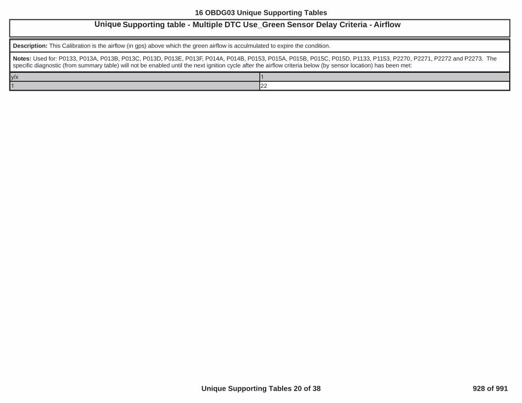
Initial Supporting table - Multiple DTC Use_Green Sensor Delay Criteria - Airflow4
Description: This Calibration is the airflow (in gps) above which the green airflow is acculmulated to expire the condition.
Notes: Used for: P0133, P013A, P013B, P013C, P013D, P013E, P013F, P014A, P014B, P0153, P015A, P015B, P015C, P015D, P1133, P1153, P2270, P2271, P2272 and P2273. Thespecific diagnostic (from summary table) will not be enabled until the next ignition cycle after the airflow criteria below (by sensor location) has been met:
y/x 1
1 22
50
16 OBDG03 Unique Supporting Tables
Unique Supporting Tables 20 of 38 928 of 991

Initial Supporting table - Multiple DTC Use_Green Sensor Delay Criteria - Limit4
Description: This Calibration is the acculmulated airflow (in grams) limit above which the green condition is expired
Notes: Used for: P0133, P013A, P013B, P013C, P013D, P013E, P013F, P014A, P014B, P0153, P015A, P015B, P015C, P015D, P1133, P1153, P2270, P2271, P2272 and P2273. Note:This feature is only enabled when the vehicle is new and cannot be enabled in service
y/x CiOXYR_O2_Bank1_Sensor1 CiOXYR_O2_Bank1_Sensor2 CiOXYR_O2_Bank2_Sensor1 CiOXYR_O2_Bank2_Sensor21 120,000 120,000 120,000 120,000
51
16 OBDG03 Unique Supporting Tables
Unique Supporting Tables 21 of 38 929 of 991

Initial Supporting table - P0101, P0106, P0121, P012B, P0236, P1101: MAP1 Residual Weight Factor based on RPM4
Description: P0101_P0106_P0121_P012B_P0236_P1101 MAP1 Residual Weight Factor based on RPM
Notes:
y/x 0 400 800 1,200 1,600 2,000 2,400 2,800 3,200 3,600 4,000 4,400 4,800 5,200 5,600 6,000 6,600
1 1.000 1.000 1.000 1.000 1.000 1.000 1.000 1.000 1.000 1.000 1.000 1.000 1.000 1.000 1.000 1.000 1.000
52
16 OBDG03 Unique Supporting Tables
Unique Supporting Tables 22 of 38 930 of 991

Initial Supporting table - P0101, P0106, P0121, P012B, P0236, P1101: MAP2 Residual Weight Factor based on RPM4
Description: P0101_P0106_P0121_P012B_P0236_P1101 MAP2 Residual Weight Factor based on RPM
Notes:
y/x 0 400 800 1,200 1,600 2,000 2,400 2,800 3,200 3,600 4,000 4,400 4,800 5,200 5,600 6,000 6,600
1 1.000 1.000 1.000 1.000 1.000 1.000 1.000 1.000 1.000 1.000 1.000 1.000 1.000 1.000 1.000 1.000 1.000
53
16 OBDG03 Unique Supporting Tables
Unique Supporting Tables 23 of 38 931 of 991

Initial Supporting table - P0101, P0106, P0121, P012B, P0236, P1101: TPS Residual Weight Factor based on RPM4
Description: P0101_P0106_P0121_P012B_P0236_P1101 TPS Residual Weight Factor based on RPM
Notes:
y/x 0 400 800 1,200 1,600 2,000 2,400 2,800 3,200 3,600 4,000 4,400 4,800 5,200 5,600 6,000 6,600
1 1.000 1.000 1.000 1.000 1.000 1.000 1.000 1.000 1.000 1.000 1.000 1.000 1.000 1.000 1.000 1.000 1.000
54
16 OBDG03 Unique Supporting Tables
Unique Supporting Tables 24 of 38 932 of 991

4
Description: P0101_P0106_P010B_P0121_P012B_P0236_P1101 MAF1 Residual Weight Factor based on MAF Est
Notes:
y/x 0 50 70 73 76 79 82 85 89 95 100 110 120 150 200 280 350
1 1 1 1 1 1 1 1 1 1 1 1 1 1 1 1 1 1
55
Unique table - P0101, P0106, P010B, P0121, P012B, P0236, P1101: MAF1 Residual Weight Factor based on MAF Est
16 OBDG03 Unique Supporting Tables
Unique Supporting Tables 25 of 38 933 of 991

Initial Supporting table - P0101, P0106, P010B, P0121, P012B, P0236, P1101: MAF1 Residual Weight Factor based on RPM4
Description: P0101_P0106_P010B_P0121_P012B_P0236_P1101 MAF1 Residual Weight Factor based on RPM
Notes:
y/x 0 400 800 1,200 1,600 2,000 2,400 2,800 3,200 3,600 4,000 4,400 4,800 5,200 5,600 6,000 6,600
1 1 1 1 1 1 1 1 1 1 1 1 1 1 1 1 1 1
56
16 OBDG03 Unique Supporting Tables
Unique Supporting Tables 26 of 38 934 of 991
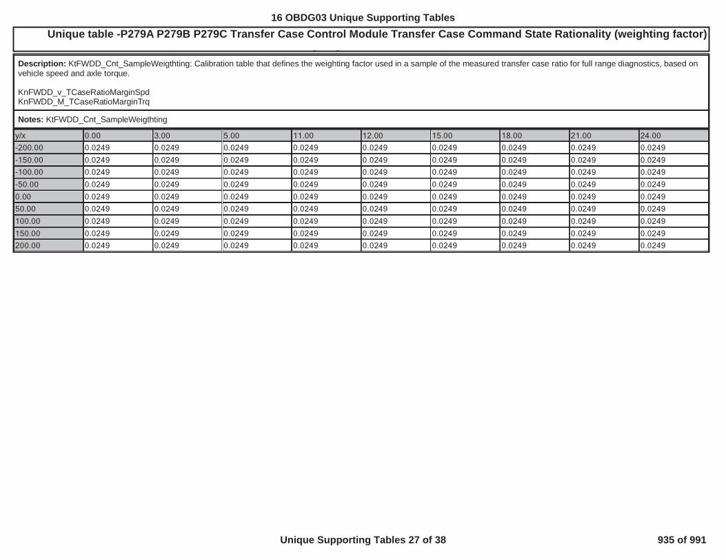
Unique table -P279A P279B P279C Transfer Case Control Module Transfer Case Command State Rationality (weighting factor) LCV_31xxN_MYOBD GROUP: GGMXOBDG03B4WD_QHR_QHE_Rev20_Pio TEST GRTEST GROUP: GGMXT02.0100 L---BIN4, FED---
Description: KtFWDD_Cnt_SampleWeigthting: Calibration table that defines the weighting factor used in a sample of the measured transfer case ratio for full range diagnostics, based onvehicle speed and axle torque.
KnFWDD_v_TCaseRatioMarginSpdKnFWDD_M_TCaseRatioMarginTrq
Notes: KtFWDD_Cnt_SampleWeigthting
y/x 0.00 3.00 5.00 11.00 12.00 15.00 18.00 21.00 24.00
-200.00 0.0249 0.0249 0.0249 0.0249 0.0249 0.0249 0.0249 0.0249 0.0249
-150.00 0.0249 0.0249 0.0249 0.0249 0.0249 0.0249 0.0249 0.0249 0.0249
-100.00 0.0249 0.0249 0.0249 0.0249 0.0249 0.0249 0.0249 0.0249 0.0249
-50.00 0.0249 0.0249 0.0249 0.0249 0.0249 0.0249 0.0249 0.0249 0.0249
0.00 0.0249 0.0249 0.0249 0.0249 0.0249 0.0249 0.0249 0.0249 0.0249
50.00 0.0249 0.0249 0.0249 0.0249 0.0249 0.0249 0.0249 0.0249 0.0249
100.00 0.0249 0.0249 0.0249 0.0249 0.0249 0.0249 0.0249 0.0249 0.0249
150.00 0.0249 0.0249 0.0249 0.0249 0.0249 0.0249 0.0249 0.0249 0.0249
200.00 0.0249 0.0249 0.0249 0.0249 0.0249 0.0249 0.0249 0.0249 0.0249
57
16 OBDG03 Unique Supporting Tables
Unique Supporting Tables 27 of 38 935 of 991

4
Description: LeFWDD_r_RatioHiBound_P279A = KeFWDD_r_TCaseHiRange + KtFWDD_r_TCaseHiRatioMargin
KnFWDD_v_TCaseRatioMarginSpdKnFWDD_M_TCaseRatioMarginTrq
Notes: LeFWDD_r_RatioHiBound_P279A
y/x 1.00 2.00 3.00 4.00 5.00 6.00 7.00 8.00 9.001.00 8.9999 8.9999 8.9999 1.3000 1.2000 1.1000 1.1000 1.1000 1.10002.00 8.9999 8.9999 8.9999 1.3000 1.2000 1.1000 1.1000 1.1000 1.10003.00 8.9999 8.9999 8.9999 1.3000 1.2000 1.1000 1.1000 1.1000 1.10004.00 8.9999 8.9999 8.9999 1.3000 1.2000 1.1000 1.1000 1.1000 1.10005.00 8.9999 8.9999 8.9999 1.3000 1.2000 1.1000 1.1000 1.1000 1.10006.00 8.9999 8.9999 8.9999 1.3000 1.2000 1.1000 1.1000 1.1000 1.10007.00 8.9999 8.9999 8.9999 1.3000 1.2000 1.1000 1.1000 1.1000 1.10008.00 8.9999 8.9999 8.9999 1.3000 1.2000 1.1000 1.1000 1.1000 1.10009.00 8.9999 8.9999 8.9999 1.3000 1.2000 1.1000 1.1000 1.1000 1.1000
58
Unique table - P279A Transfer Case Control Module Transfer Case Command State Rationality (margin of error high)
16 OBDG03 Unique Supporting Tables
Unique Supporting Tables 28 of 38 936 of 991

4
Description: LeFWDD_r_RatioLoBound_P279A = KeFWDD_r_TCaseHiRange - KtFWDD_r_TCaseHiRatioMargin
KnFWDD_v_TCaseRatioMarginSpdKnFWDD_M_TCaseRatioMarginTrq
Notes: LeFWDD_r_RatioLoBound_P279A
y/x 1 2 3 4 5 6 7 8 91 -7.00 -7.00 -7.00 0.70 0.80 0.90 0.90 0.90 0.902 -7.00 -7.00 -7.00 0.70 0.80 0.90 0.90 0.90 0.903 -7.00 -7.00 -7.00 0.70 0.80 0.90 0.90 0.90 0.904 -7.00 -7.00 -7.00 0.70 0.80 0.90 0.90 0.90 0.905 -7.00 -7.00 -7.00 0.70 0.80 0.90 0.90 0.90 0.906 -7.00 -7.00 -7.00 0.70 0.80 0.90 0.90 0.90 0.907 -7.00 -7.00 -7.00 0.70 0.80 0.90 0.90 0.90 0.908 -7.00 -7.00 -7.00 0.70 0.80 0.90 0.90 0.90 0.909 -7.00 -7.00 -7.00 0.70 0.80 0.90 0.90 0.90 0.90
59
Unique table - P279A Transfer Case Control Module Transfer Case Command State Rationality (margin of error low)
16 OBDG03 Unique Supporting Tables
Unique Supporting Tables 29 of 38 937 of 991

4
Description: LeFWDD_r_RatioHiBound_P279B = KeFWDD_r_TCaseLoRange + KtFWDD_r_TCaseLoRatioMargin
KnFWDD_v_TCaseRatioMarginSpdKnFWDD_M_TCaseRatioMarginTrq
Notes: LeFWDD_r_RatioHiBound_P279B
y/x 1.00 2.00 3.00 4.00 5.00 6.00 7.00 8.00 9.001.00 10.7098 10.7098 10.7098 3.0100 2.9099 2.8099 2.8099 2.8099 2.80992.00 10.7098 10.7098 10.7098 3.0100 2.9099 2.8099 2.8099 2.8099 2.80993.00 10.7098 10.7098 10.7098 3.0100 2.9099 2.8099 2.8099 2.8099 2.80994.00 10.7098 10.7098 10.7098 3.0100 2.9099 2.8099 2.8099 2.8099 2.80995.00 10.7098 10.7098 10.7098 3.0100 2.9099 2.8099 2.8099 2.8099 2.80996.00 10.7098 10.7098 10.7098 3.0100 2.9099 2.8099 2.8099 2.8099 2.80997.00 10.7098 10.7098 10.7098 3.0100 2.9099 2.8099 2.8099 2.8099 2.80998.00 10.7098 10.7098 10.7098 3.0100 2.9099 2.8099 2.8099 2.8099 2.80999.00 10.7098 10.7098 10.7098 3.0100 2.9099 2.8099 2.8099 2.8099 2.8099
60
Unique table - P279B Transfer Case Control Module Transfer Case Command State Rationality (margin of error high)
16 OBDG03 Unique Supporting Tables
Unique Supporting Tables 30 of 38 938 of 991

4
Description: LeFWDD_r_RatioLoBound_P279B = KeFWDD_r_TCaseLoRange - KtFWDD_r_TCaseLoRatioMargin
KnFWDD_v_TCaseRatioMarginSpdKnFWDD_M_TCaseRatioMarginTrq
Notes: LeFWDD_r_RatioLoBound_P279B
y/x 1.00 2.00 3.00 4.00 5.00 6.00 7.00 8.00 9.001.00 -5.2899 -5.2899 -5.2899 2.4099 2.5100 2.6100 2.6100 2.6100 2.61002.00 -5.2899 -5.2899 -5.2899 2.4099 2.5100 2.6100 2.6100 2.6100 2.61003.00 -5.2899 -5.2899 -5.2899 2.4099 2.5100 2.6100 2.6100 2.6100 2.61004.00 -5.2899 -5.2899 -5.2899 2.4099 2.5100 2.6100 2.6100 2.6100 2.61005.00 -5.2899 -5.2899 -5.2899 2.4099 2.5100 2.6100 2.6100 2.6100 2.61006.00 -5.2899 -5.2899 -5.2899 2.4099 2.5100 2.6100 2.6100 2.6100 2.61007.00 -5.2899 -5.2899 -5.2899 2.4099 2.5100 2.6100 2.6100 2.6100 2.61008.00 -5.2899 -5.2899 -5.2899 2.4099 2.5100 2.6100 2.6100 2.6100 2.61009.00 -5.2899 -5.2899 -5.2899 2.4099 2.5100 2.6100 2.6100 2.6100 2.6100
61
Unique table - P279B Transferr Case Co trol Module Transfer Case Command State Rationality (margin of error low)
16 OBDG03 Unique Supporting Tables
Unique Supporting Tables 31 of 38 939 of 991

4
Description: LeFWDD_r_RatioHiBound1_P279C = KeFWDD_r_TCaseHiRange + KtFWDD_r_TCaseNeutRatioMargin
KnFWDD_v_TCaseRatioMarginSpdKnFWDD_M_TCaseRatioMarginTrq
Notes: LeFWDD_r_RatioHiBound1_P279C
y/x 1.00 2.00 3.00 4.00 5.00 6.00 7.00 8.00 9.001.00 8.9999 8.9999 8.9999 2.0000 1.1000 1.1000 1.1000 1.1000 1.10002.00 8.9999 8.9999 8.9999 2.0000 2.0000 2.0000 1.5000 1.5000 1.50003.00 8.9999 8.9999 8.9999 3.0000 3.0000 3.0000 2.0000 2.0000 2.00004.00 8.9999 8.9999 8.9999 5.0000 5.0000 5.0000 3.0000 3.0000 3.00005.00 8.9999 8.9999 8.9999 8.9999 8.9999 8.9999 8.9999 8.9999 8.99996.00 8.9999 8.9999 8.9999 5.0000 5.0000 5.0000 3.0000 3.0000 3.00007.00 8.9999 8.9999 8.9999 3.0000 3.0000 3.0000 2.0000 2.0000 2.00008.00 8.9999 8.9999 8.9999 2.0000 2.0000 2.0000 1.5000 1.5000 1.50009.00 8.9999 8.9999 8.9999 2.0000 1.1000 1.1000 1.1000 1.1000 1.1000
62
Unique table - P279C Trransfer Case Control Module Transfer Case Command State Rationality (margin of error high 1)
16 OBDG03 Unique Supporting Tables
Unique Supporting Tables 32 of 38 940 of 991

4
Description: LeFWDD_r_RatioHiBound2_P279C = KeFWDD_r_TCaseLoRange + KtFWDD_r_TCaseNeutRatioMargin
KnFWDD_v_TCaseRatioMarginSpdKnFWDD_M_TCaseRatioMarginTrq
Notes: LeFWDD_r_RatioHiBound2_P279C
y/x 1.00 2.00 3.00 4.00 5.00 6.00 7.00 8.00 9.001.00 10.7098 10.7098 10.7098 3.7100 2.8099 2.8099 2.8099 2.8099 2.80992.00 10.7098 10.7098 10.7098 3.7100 3.7100 3.7100 3.2100 3.2100 3.21003.00 10.7098 10.7098 10.7098 4.7100 4.7100 4.7100 3.7100 3.7100 3.71004.00 10.7098 10.7098 10.7098 6.7100 6.7100 6.7100 4.7100 4.7100 4.71005.00 10.7098 10.7098 10.7098 10.7098 10.7098 10.7098 10.7098 10.7098 10.70986.00 10.7098 10.7098 10.7098 6.7100 6.7100 6.7100 4.7100 4.7100 4.71007.00 10.7098 10.7098 10.7098 4.7100 4.7100 4.7100 3.7100 3.7100 3.71008.00 10.7098 10.7098 10.7098 3.7100 3.7100 3.7100 3.2100 3.2100 3.21009.00 10.7098 10.7098 10.7098 3.7100 2.8099 2.8099 2.8099 2.8099 2.8099
63
Unique table - P279C Trransfer Case Control Module Transfer Case Command State Rationality (margin of error high 2)
16 OBDG03 Unique Supporting Tables
Unique Supporting Tables 33 of 38 941 of 991

4
Description: LeFWDD_r_RatioLoBound1_P279C = KeFWDD_r_TCaseHiRange - KtFWDD_r_TCaseNeutRatioMargin
KnFWDD_v_TCaseRatioMarginSpdKnFWDD_M_TCaseRatioMarginTrq
Notes: LeFWDD_r_RatioLoBound1_P279C
y/x 1.00 2.00 3.00 4.00 5.00 6.00 7.00 8.00 9.001.00 -6.9999 -6.9999 -6.9999 0.0000 0.9000 0.9000 0.9000 0.9000 0.90002.00 -6.9999 -6.9999 -6.9999 0.0000 0.0000 0.0000 0.5000 0.5000 0.50003.00 -6.9999 -6.9999 -6.9999 -1.0000 -1.0000 -1.0000 0.0000 0.0000 0.00004.00 -6.9999 -6.9999 -6.9999 -3.0000 -3.0000 -3.0000 -1.0000 -1.0000 -1.00005.00 -6.9999 -6.9999 -6.9999 -6.9999 -6.9999 -6.9999 -6.9999 -6.9999 -6.99996.00 -6.9999 -6.9999 -6.9999 -3.0000 -3.0000 -3.0000 -1.0000 -1.0000 -1.00007.00 -6.9999 -6.9999 -6.9999 -1.0000 -1.0000 -1.0000 0.0000 0.0000 0.00008.00 -6.9999 -6.9999 -6.9999 0.0000 0.0000 0.0000 0.5000 0.5000 0.50009.00 -6.9999 -6.9999 -6.9999 0.0000 0.9000 0.9000 0.9000 0.9000 0.9000
64
Unique table - P279C Transfer Case Control Module Transfer Case Command State Rationality (margin of error low 1)
16 OBDG03 Unique Supporting Tables
Unique Supporting Tables 34 of 38 942 of 991

4
Description: LeFWDD_r_RatioLoBound2_P279C = KeFWDD_r_TCaseLoRange - KtFWDD_r_TCaseNeutRatioMargin
KnFWDD_v_TCaseRatioMarginSpdKnFWDD_M_TCaseRatioMarginTrq
Notes: LeFWDD_r_RatioLoBound2_P279C
y/x 1.00 2.00 3.00 4.00 5.00 6.00 7.00 8.00 9.001.00 -5.2899 -5.2899 -5.2899 1.7100 2.6100 2.6100 2.6100 2.6100 2.61002.00 -5.2899 -5.2899 -5.2899 1.7100 1.7100 1.7100 2.2100 2.2100 2.21003.00 -5.2899 -5.2899 -5.2899 0.7100 0.7100 0.7100 1.7100 1.7100 1.71004.00 -5.2899 -5.2899 -5.2899 -1.2900 -1.2900 -1.2900 0.7100 0.7100 0.71005.00 -5.2899 -5.2899 -5.2899 -5.2899 -5.2899 -5.2899 -5.2899 -5.2899 -5.28996.00 -5.2899 -5.2899 -5.2899 -1.2900 -1.2900 -1.2900 0.7100 0.7100 0.71007.00 -5.2899 -5.2899 -5.2899 0.7100 0.7100 0.7100 1.7100 1.7100 1.71008.00 -5.2899 -5.2899 -5.2899 1.7100 1.7100 1.7100 2.2100 2.2100 2.21009.00 -5.2899 -5.2899 -5.2899 1.7100 2.6100 2.6100 2.6100 2.6100 2.6100
65
Unique Supporting table - P279C Transfer Case Control Module Transfer Case Command State Rationality (margin of error low 2)
16 OBDG03 Unique Supporting Tables
Unique Supporting Tables 35 of 38 943 of 991

Initial Supporting table - P0420_P0430_CatmonMinAirflowForWarmCatalystDetermination
Description: This is a 1x3 table with the axis being engine coolant temperature. The implementation of this cal value as a table also included some changes to the way that theWarmedUpEvents counter increments and resets. To summarize, whenever WarmedUpEvents resets to 0 (this could be either at startup, if the closed throttle time exceeds a cal value, or ifthe predicted exhaust temperature falls below the ExhWarmMin cal value), the appropriate MinAirflowToWrmupCat value is chosen from the table based on engine coolant at the time theWarmedUpEvents counter reset to 0. This cal value is used along with the min exhaust temp to increment the WarmedUpEvents counter.
Notes: KtCATD_dm_MinAirFlowToWrmCat - Used for P0420 and P0430. Axis is the engine coolant and the output is the minimum airflow required to warmup the catalyst.
y/x 0 45 90
1 10 9 8
16 OBDG03 Unique Supporting Tables
Unique Supporting Tables 36 of 38 944 of 991
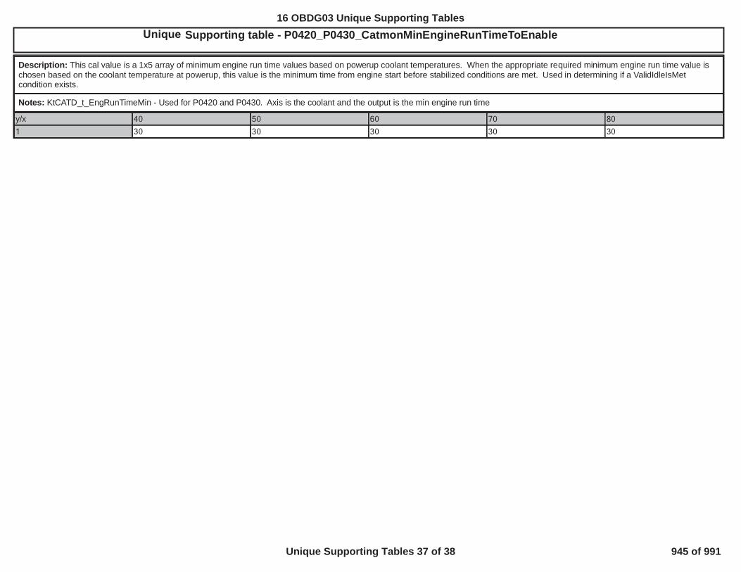
Initial Supporting table - P0420_P0430_CatmonMinEngineRunTimeToEnable4
Description: This cal value is a 1x5 array of minimum engine run time values based on powerup coolant temperatures. When the appropriate required minimum engine run time value ischosen based on the coolant temperature at powerup, this value is the minimum time from engine start before stabilized conditions are met. Used in determining if a ValidIdleIsMetcondition exists.
Notes: KtCATD_t_EngRunTimeMin - Used for P0420 and P0430. Axis is the coolant and the output is the min engine run time
y/x 40 50 60 70 80
1 30 30 30 30 30
16 OBDG03 Unique Supporting Tables
Unique Supporting Tables 37 of 38 945 of 991

Initial Supporting table - P00B6_Fail if power up ECT exceeds RCT by these values
Description: KtTHMD_T_DCRD_FastFailTempDiff
Notes: X axis is IAT Temperature at Power up (° C), Z axis is the Fast Failure temp difference (° C) The 17 X-axis breakpoints for the table below are (L to R) -40, -28, -16, -4, 8, 20, 32, 44,56, 68, 80, 92, 104, 116, 128, 140 and 152. Note: Remove for applications with single coolant sensor
y/x -40 -28 -16 -4 8 20 32 44 56 68 80 92 104 116 128 140 1521 80 80 80 60 60 40 40 30 30 30 30 30 30 30 30 30 30
7
16 OBDG03 Unique Supporting Tables
Unique Supporting Tables 38 of 38 946 of 991

Bundle Name: 5VoltReferenceB_FAP0651Bundle Name: 5VoltReferenceMAP_OOR_FltP0697Bundle Name: A/F Imbalance Bank1P219ABundle Name: AAP_SnsrCktFANaturally aspirated: P2228, P2229. Turbocharged: P0237, P0238Bundle Name: AAP_SnsrCktFPNaturally aspirated: P2228, P2229. Turbocharged: P0237, P0238Bundle Name: AAP_SnsrFANaturally Aspirated: P2227, P2228, P2229, P2230. Turbocharged: P0237, P0238.Bundle Name: AAP2_SnsrCktFAP2228, P2229Bundle Name: AAP2_SnsrCktFPP2228, P2229Bundle Name: AAP2_SnsrFAP2227, P2228, P2229, P2230Bundle Name: AcceleratorPedalFailureP2122, P2123, P2127, P2128, P2138, P0697, P06A3Bundle Name: AfterThrottlePressureFANaturally Aspirated or Turbocharged: P0106, P0107, P0108. Supercharged: P012B, P012C, P012D.Bundle Name: AIR System FAP0411, P2440, P2444Bundle Name: AmbientAirDefaultBaro Sensor Present: P2227, P2228, P2229, P2230. No Baro Sensor Present: P0101, P0102, P0103, P0106, P0107, P0108, P0111, P0112, P0113, P0114, P0121, P0122, P0123,P012B, P012C, P012D, P0222,P0223, P1221
Bundle Name: AmbPresDfltdStatusBaro Sensor Present: P2227, P2228, P2229, P2230. No Baro Sensor Present: P0101, P0102, P0103, P0106, P0107, P0108, P0111, P0112, P0113, P0114, P0121, P0122, P0123,P012B, P012C, P012D, P0222,P0223, P1221
Bundle Name: AmbPresSnsrCktFAP2228, P2229Bundle Name: AnyCamPhaser_FAP0010, P0011, P0013, P0014, P0020, P0021, P0023, P0024, P2088, P2089, P2090, P2091, P2092, P2093, P2094, P2095, P05CC, P05CD, P05CE, P05CF,
Bundle Name: AnyCamPhaser_TFTKOP0010, P0011, P0013, P0014, P0020, P0021, P0023, P0024, P2088, P2089, P2090, P2091, P2092, P2093, P2094, P2095, P05CC, P05CD, P05CE, P05CF,
16 OBDG03 Fault Bundle Definitions
Fault Bundle Definitions 1 of 9 947 of 991
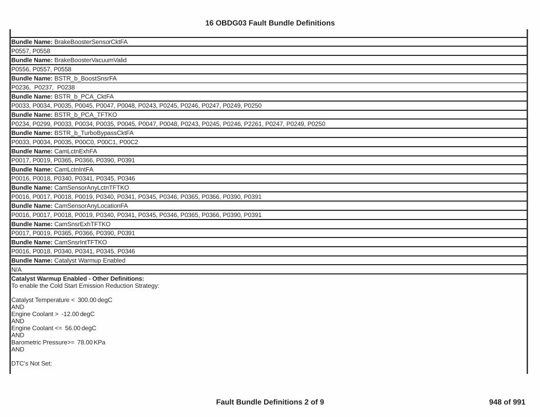
Bundle Name: BrakeBoosterSensorCktFAP0557, P0558Bundle Name: BrakeBoosterVacuumValidP0556, P0557, P0558Bundle Name: BSTR_b_BoostSnsrFAP0236, P0237, P0238Bundle Name: BSTR_b_PCA_CktFAP0033, P0034, P0035, P0045, P0047, P0048, P0243, P0245, P0246, P0247, P0249, P0250Bundle Name: BSTR_b_PCA_TFTKOP0234, P0299, P0033, P0034, P0035, P0045, P0047, P0048, P0243, P0245, P0246, P2261, P0247, P0249, P0250Bundle Name: BSTR_b_TurboBypassCktFAP0033, P0034, P0035, P00C0, P00C1, P00C2Bundle Name: CamLctnExhFAP0017, P0019, P0365, P0366, P0390, P0391Bundle Name: CamLctnIntFAP0016, P0018, P0340, P0341, P0345, P0346Bundle Name: CamSensorAnyLctnTFTKOP0016, P0017, P0018, P0019, P0340, P0341, P0345, P0346, P0365, P0366, P0390, P0391Bundle Name: CamSensorAnyLocationFAP0016, P0017, P0018, P0019, P0340, P0341, P0345, P0346, P0365, P0366, P0390, P0391Bundle Name: CamSnsrExhTFTKOP0017, P0019, P0365, P0366, P0390, P0391Bundle Name: CamSnsrIntTFTKOP0016, P0018, P0340, P0341, P0345, P0346Bundle Name: Catalyst Warmup EnabledN/ACatalyst Warmup Enabled - Other Definitions:To enable the Cold Start Emission Reduction Strategy:
Catalyst Temperature < degC300.00ANDEngine Coolant > degC-12.00ANDEngine Coolant <= degC56.00ANDBarometric Pressure>= KPa78.00AND
DTC's Not Set:
16 OBDG03 Fault Bundle Definitions
Fault Bundle Definitions 2 of 9 948 of 991

ECT_Sensor_FAMAP_SensorFA
The Cold Start Emission Reduction Strategy will remain active until:
Engine Run Time > This Extended Engine run time exit is a function of percent ethanol and Catmons NormRatioEWMA.P050D_P1400_CatalystLightOffExtendedEngineRunTimeExitRefer to "Supporting Tables" for details.
OR
Catalyst Temperature >= degC800.00ANDEngine Run Time >= seconds22.00
OR
Barometric Pressure < KPa78.00
Bundle Name: ClutchPstnSnsr FAP0806, P0807, P0808Bundle Name: CrankSensor_FAP0335, P0336Bundle Name: CrankSensor_TFTKOP0335, P0336Bundle Name: CylDeacAllDriverFaultP3401, P03403, P03404, P3409, P03411, P03412, P3417, P3419, P3420, P3425, P3427, P3428, P3433, P3435, P3436, P3441, P3443, P3444, P3449, P3451,P3452, P3457, P3459, P3460Bundle Name: CylDeacDriverFaultP3401, P03403, P03404, P3409, P03411, P03412, P3417, P3419, P3420, P3425, P3427, P3428, P3433, P3435, P3436, P3441, P3443, P3444, P3449, P3451,P3452, P3457, P3459, P3460Bundle Name: ECT_Sensor_Ckt_FAP0117, P0118Bundle Name: ECT_Sensor_Ckt_FPP0117, P0118Bundle Name: ECT_Sensor_Ckt_TFTKOP0117, P0118Bundle Name: ECT_Sensor_DefaultDetectedP0116, P0117, P0118, P0119, P111EBundle Name: ECT_Sensor_FAP0116, P0117, P0118, P0119, P0128, P111EBundle Name: ECT_Sensor_Perf_FAP0116, P111E
16 OBDG03 Fault Bundle Definitions
Fault Bundle Definitions 3 of 9 949 of 991

Bundle Name: EGRValve_FPP0405, P0406, P042EBundle Name: EGRValveCircuit_FAP0403, P0404, P0405, P0406, P0489, P0490Bundle Name: EGRValvePerformance_FAP0401, P042EBundle Name: EngineMisfireDetected_FAP0300, P0301, P0302, P0303, P0304, P0305, P0306, P0307, P0308Bundle Name: EngineModeNotRunTimer_FAP2610Bundle Name: EngineModeNotRunTimerErrorP2610Bundle Name: EnginePowerLimitedP0068, P00C8, P00C9, P00CA, P0090, P0091, P0092, P0122, P0123, P0191, P0192, P0193, P0222, P0223, P0601, P0604, P0606, P0697, P06A3, P06DB,P06D2, P06DE, P0A1D, P1104, P127A, P127C, P127D, P15F2, P160D, P160E, P1682, P16A0, P16A1, P16A2, P16A7, P16F3, P2100, P2101, P2102, P2103,P2122, P2123, P2127, P2128, P2135, P2138, P215B, P2176, P228C, P228D, U0073, U0074, U0293, U1817Bundle Name: EngineTorqueEstInaccurateEngineMisfireDetected_FA, FuelInjedtorCircuit_FA, FuelInjedtorCircuit_TFTKO, FuelTrimSystemB1_FA, FuelTrimSystemB2_FA, MAF_SensorTFTKO, MAP_SensorTFTKO,EGRValvePerformance_FA, P16F3EngineTorqueEstInaccurate - Other Definitions:P16F3 with GetXOYR_b_SecurityFlt (CeXOYR_e_MAPR_AfterThrotPresFlt, CeXOYR_e_MAPR_EngineVacuumFlt, CeXOYR_e_MAPR_IntkMnfdPresFlt,CeXOYR_e_MAFR_Ahead1vs2FinalFlt)Bundle Name: EngOilPressureSensorCktFAP0522, P0523Bundle Name: EngOilPressureSensorFAP0521, P0522, P0523Bundle Name: EngOilTempFAEngOilTempSensorCircuitFA, EngOilModeledTempValid, P16F3EngOilTempFA - Other Definitions:P16F3 with GetXOYR_b_SecurityFlt(CeXOYR_e_EOTR_SecurityFlt)Bundle Name: Ethanol Composition Sensor FAP0178, P0179, P2269Bundle Name: EvapEmissionSystem_FAP0455, P0446Bundle Name: EvapExcessPurgePsbl_FAELCP sealed/vented fuel system, P0442, P0455, P0458 OR Conventional fuel system, P0442, P0455, P0458, P0496Bundle Name: EvapFlowDuringNonPurge_FAP0496Bundle Name: EvapPurgeSolenoidCircuit_FA
16 OBDG03 Fault Bundle Definitions
Fault Bundle Definitions 4 of 9 950 of 991

P0443, P0458, P0459Bundle Name: EvapSmallLeak_FAP0442Bundle Name: EvapVentSolenoidCircuit_FAP0449, P0498, P0499Bundle Name: FHPR_b_FRP_SnsrCkt_FAP0192, P0193, P127C, P127D, P16E4, P16E5, P128A, P128B, 128FBundle Name: FHPR_b_FRP_SnsrCkt_TFTKOP0192, P0193, , P127C, P127D, P16E4, P16E5, P128A, P128B, 128FBundle Name: FHPR_b_PumpCkt_FAP0090, P0091, P0092, P00C8, P00C9, P00CABundle Name: FHPR_b_PumpCkt_TFTKOP0090, P0091, P0092, P00C8, P00C9, P00CABundle Name: FourWheelDriveLowStateInvalidP2771Bundle Name: FuelInjectorCircuit_FAPFI: P0201, P0202, P0203, P0204, P0205, P0206, P0207, P0208, P0261, P0264, P0267, P0270, P0273, P0276, P0279, P0282, P0262, P0265, P0268, P0271,P0274, P0277, P0280, P0283 SIDI: P0201, P0202, P0203, P0204, P0205, P0206, P0207, P0208, P0261, P0264, P0267, P0270, P0273, P0276, P0279, P0282, P0262,P0265, P0268, P0271, P0274, P0277, P0280, P0283, P2147, P2150, P2153, P2156, P216B, P216E, P217B, P217E, P2148, P2151, P2154, P2157, P216C,P216F, P217C, P217F, P1248, P1249, P124A, P124B, P124C, P124D, P124E, P124F
Bundle Name: FuelInjectorCircuit_TFTKOPFI: P0201, P0202, P0203, P0204, P0205, P0206, P0207, P0208, P0261, P0264, P0267, P0270, P0273, P0276, P0279, P0282, P0262, P0265, P0268, P0271,P0274, P0277, P0280, P0283 SIDI: P0201, P0202, P0203, P0204, P0205, P0206, P0207, P0208, P0261, P0264, P0267, P0270, P0273, P0276, P0279, P0282, P0262,P0265, P0268, P0271, P0274, P0277, P0280, P0283, P2147, P2150, P2153, P2156, P216B, P216E, P217B, P217E, P2148, P2151, P2154, P2157, P216C,P216F, P217C, P217F, P1248, P1249, P124A, P124B, P124C, P124D, P124E, P124F
Bundle Name: FuelPumpRlyCktFAP0627, P0628, P0629Bundle Name: FuelTankPressureSnsrCkt_FAP0452, P0453Bundle Name: FuelTrimSystemB1_FAP0171, P0172, P11E9 , P11EABundle Name: FuelTrimSystemB2_FAP0174, P0175, P11EB, P11ECBundle Name: HumTempSnsrCktFAP0097, P0098Bundle Name: IAC_SystemRPM_FAP0506, P0507Bundle Name: IAT_SensorCircuitFAP0112, P0113
16 OBDG03 Fault Bundle Definitions
Fault Bundle Definitions 5 of 9 951 of 991

Bundle Name: IAT_SensorCircuitFPP0112, P0113Bundle Name: IAT_SensorFAP0111, P0112, P0113, P0114Bundle Name: IAT_SensorTFTKOP0111, P0112, P0113, P0114Bundle Name: IgnitionOffTimeValidP2610Bundle Name: IgnitionOutputDriver_FAP0351, P0352, P0353, P0354, P0355, P0356, P0357, P0358, P2300, P2301, P2303, P2304, P2306, P2307, P2309, P2310, P2312, P2313, P2315, P2316,P2318, P2319, P2321, P2322
Bundle Name: MAF_SensorCircuitFAP0102, P0103, P010C, P010DBundle Name: MAF_SensorFAP0101, P0102, P0103, P010B, P010C, P010DBundle Name: MAF_SensorTFTKOP0101, P0102, P0103, P010B, P010C, P010DBundle Name: MAP_EngineVacuumStatusP0106, P0107, P0108 Fault Active OR P0107, P0108 Fault PendingBundle Name: MAP_SensorCircuitFAP0107, P0108Bundle Name: MAP_SensorCircuitFPP0107, P0108Bundle Name: MAP_SensorFAP0106, P0107, P0108Bundle Name: MAP_SensorTFTKOP0106, P0107, P0108Bundle Name: MnfdTempSensorCktFATurbocharged or Supercharged, with Humidity sensor: P00EA, P00EB. Turbocharged or Supercharged, without Humidity sensor: P0097, P0098. Naturally Aspirated: P0112, P0113.Bundle Name: MnfdTempSensorCktFPTurbocharged or Supercharged, with Humidity sensor: P00EA, P00EB. Turbocharged or Supercharged, without Humidity sensor: P0097, P0098. Naturally Aspirated: P0112, P0113.Bundle Name: MnfdTempSensorFATurbocharged or Supercharged, with Humidity sensor: P00E9, P00EA, P00EB, P00EC. Turbocharged or Supercharged, without Humidity sensor: P0096, P0097, P0098, P0099.Naturally Aspirated: P0111, P0112, P0113, P0114.Bundle Name: O2S_Bank_1_Sensor_1_FAP2A00, P0131, P0132, P0133, P0134, P0135, P0053, P1133, P015A, P015B, P0030Bundle Name: O2S_Bank_1_Sensor_2_FAP013A, P013B, P013E, P013F, P2270, P2271, P0137, P0138, P0140, P0141, P0054, P0036
16 OBDG03 Fault Bundle Definitions
Fault Bundle Definitions 6 of 9 952 of 991
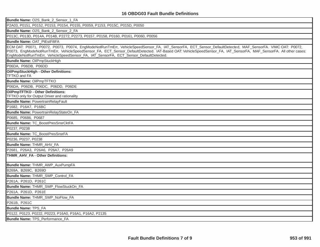
Bundle Name: O2S_Bank_2_Sensor_1_FAP2A03, P0151, P0152, P0153, P0154, P0155, P0059, P1153, P015C, P015D, P0050Bundle Name: O2S_Bank_2_Sensor_2_FAP013C, P013D, P014A, P014B, P2272, P2273, P0157, P0158, P0160, P0161, P0060, P0056Bundle Name: OAT_PtEstFiltFAECM OAT: P0071, P0072, P0073, P0074, EngModeNotRunTmErr, VehicleSpeedSensor_FA, IAT_SensorFA, ECT_Sensor_DefaultDetected, MAF_SensorFA. VIMC OAT: P0072,P0073, EngModeNotRunTmErr, VehicleSpeedSensor_FA, ECT_Sensor_DefaultDetected. IAT-Based OAT: VehicleSpeedSensor_FA, IAT_SensorFA, MAF_SensorFA. All other cases:EngModeNotRunTmErr, VehicleSpeedSensor_FA, IAT_SensorFA, ECT_Sensor_DefaultDetected.Bundle Name: OilPmpStuckHighP06DA, P06DB, P06DDOilPmpStuckHigh - Other Definitions:TFTKO and FABundle Name: OilPmpTFTKOP06DA, P06DB, P06DC, P06DD, P06DEOilPmpTFTKO - Other Definitions:TFTKO only for Output Driver and rationalityBundle Name: PowertrainRelayFaultP1682, P16A7, P16BCBundle Name: PowertrainRelayStateOn_FAP0685, P0686, P0687Bundle Name: TC_BoostPresSnsrCktFAP0237, P0238Bundle Name: TC_BoostPresSnsrFAP0236, P0237, P0238Bundle Name: THMR_AHV_FAP2681, P26A3, P26A6, P26A7, P26A9THMR_AHV_FA - Other Definitions:
Bundle Name: THMR_AWP_AuxPumpFAB269A, B269C, B269DBundle Name: THMR_SWP_Control_FAP261A, P261D, P261CBundle Name: THMR_SWP_FlowStuckOn_FAP261A, P261D, P261EBundle Name: THMR_SWP_NoFlow_FAP261B, P261CBundle Name: TPS_FAP0122, P0123, P0222, P0223, P16A0, P16A1, P16A2, P2135Bundle Name: TPS_Performance_FA
16 OBDG03 Fault Bundle Definitions
Fault Bundle Definitions 7 of 9 953 of 991

P0068, P0121, P1104, P2100, P2101, P2102, P2103Bundle Name: TPS_ThrottleAuthorityDefaultedP0068, P0122, P0123, P0222, P0223, P16F3, P16A0, P16A1, P16A2, P1104, P2100, P2101, P2102, P2103, P2135Bundle Name: Transmission Oil Temperature ValidityP0667, P0668, P0669, P0711, P0712, P0713Bundle Name: Transmission Output Shaft Angular Velocity ValidityP0722, P0723, P077C, P077DBundle Name: Transmission Turbine Angular Velocity ValidityP0716, P0717, P07BF, P07C0Bundle Name: TransmissionEngagedState_FAP1824, P182A, P182B, P182C, P182D, P182E, P182F, P1838, P1839, P1840, P1841, P18B5, P18B6, P18B7, P18B8, P18B9, P18BA, P18BB, P18BC, P18BD,P18BE, P18BF, P18C0, P18C1, P18C2, P18C3, P1915
Bundle Name: VCER_TorqueSecurityP16F3VCER_TorqueSecurity - Other Definitions:P16F3 with GetXOYR_b_SecurityFlt(CeXOYR_e_AFM_PreloadAreaFlt, CeXOYR_e_AFM_PreloadTimerFlt, CeXOYR_e_AFM_DualPreloadAreaFlt, CeXOYR_e_CDAR_SecurityFlt)Bundle Name: VehicleSpeedSensor_FAP0502, P0503, P0722, P0723Bundle Name: VehicleSpeedSensorErrorP0502, P0503, P0722, P0723Bundle Name: WRAF_Bank_1_FAP0131, P0132, P064D, P223C, P223EBundle Name: WRAF_Bank_2_FAP0151, P0152, P064E, P223D, P223F
16 OBDG03 Fault Bundle Definitions
Fault Bundle Definitions 8 of 9 954 of 991

Bundle Name: ClutchPstnSnsrCktHi FAP0808Bundle Name: ClutchPstnSnsrCktLo FAP0807Bundle Name: CrankSensor_FAP0335, P0336Bundle Name: Transmission Output Shaft Angular Velocity ValidityP0722, P0723, P077C, P077DBundle Name: VehicleSpeedSensor_FAP0502, P0503, P0722, P0723
29
16 OBDG03 Fault Bundle Definitions
Fault Bundle Definitions 9 of 9 955 of 991

Component/System
FaultCode
MonitorStrategy
DescriptionMalfunction
CriteriaThreshold
ValueSecondaryParameters
EnableConditions
TimeRequired
MILIllumination
Fuel RailPressure (FRP)SensorPerformance(rationality)
P018B This DTCdetects a fuelpressure sensorresponse stuckwithin the normaloperating range
Absolute value of fuelpressure change assensed during intrusivetest.
<= 30 kPa
1. FRP Circuit Low DTC(P018C) not active
Frequency:Continuous; 12.5ms loop.60 secondsbetween intrusivetests that pass
Intrusive testrequested if fuelsystem is clampedfor >= 5 seconds orfuel pressure errorvariance <=typically (0.3 to 0.6)(calculated over a2.5sec period);otherwise reportpass
DTC Type B2 trips
2. FRP Circuit High DTC(P018D) not active3. FuelPump Circuit Low DTC (P0231)
not active
Duration of intrusivetest is fuelingrelated (5 to 12seconds).
4. FuelPump Circuit High DTC(P0232)
not active
5. FuelPump Circuit Open DTC(P023F)
not active Intrusive test is runwhen fuel flow isbelow Max allowedfuel flow rate(Typical values inthe range of 11 to50 g/s)
6. Reference Voltage DTC (P0641) not active7. Fuel Pump Control Module DriverOver-temperature DTC (P064A)
not active
8. Control Module InternalPerformance DTC (P0606)
not active
9. Engine run time >=5 seconds10. Emissions fuel level(PPEI $3FB)
not low
11. Fuel pump control enabled12. Fuel pump control state normal or FRP
Rationality control13. Engine fuel flow > 0.047 g/s
16 OBDG03 Electronically Regulated Fuel System (ERFS) and no Active Grill Air Shutters
ERFS and no Active Grill Air Shutters Section 1 of 7 956 of 991

Component/System
FaultCode
MonitorStrategy
DescriptionMalfunction
CriteriaThreshold
ValueSecondaryParameters
EnableConditions
TimeRequired
MILIllumination
14. ECM fuel control system failure(PPEI $1ED)
failure has notoccurred
Fuel RailPressure (FRP)Sensor CircuitLow Voltage
P018C This DTCdetects if the fuelpressure sensorcircuit is shortedlow
FRP sensor voltage < 0.14 V
Ignition Run or Crank
72 failures out of 80samples
1 sample/12.5 ms
DTC Type B2 trips
Fuel RailPressure (FRP)Sensor CircuitHigh Voltage
P018D This DTCdetects if the fuelpressure sensorcircuit is shortedhigh
FRP sensor voltage > 4.86 V
Ignition Run or Crank
72 failures out of 80samples
1 sample/12.5 ms
DTC Type B2 trips
Fuel PumpControl CircuitLow Voltage
P0231 This DTCdetects if the fuelpump controlcircuit is shortedto low
Fuel Pump Current > 14.48A
Ignition Run or Crank
72 test failures in 80test samples if FuelPump Current<100A
DTC Type A1 trip
ORIgnition AccessoryOR 1 sample/12.5 msFuel Pump Control enabledANDIgnition Run/Crank Voltage 9V < voltage < 32V
Fuel PumpControl CircuitHigh Voltage
P0232 This DTCdetects if the fuelpump controlcircuit is shortedto high
Voltage measured at fuelpump circuit
> 3.86 V Commanded fuel pump output 0% duty cycle (off) 36 test failures in 40test samples;1 sample/12.5ms
DTC Type B2 trips
Fuel pump control enable False Pass/Faildetermination madeonly once per trip
Time that above conditions are met >=4.0 secondsFuel PumpControl Circuit(Open)
P023F This DTCdetects if the fuelpump controlcircuit is open
Fuel Pump Current <=0.5A
Ignition Run or Crank
72 test failures in 80test samples;1 sample/12.5ms
DTC Type A1 trip
AND ORFuel Pump Duty Cycle >20% Ignition Accessory
ORFuel Pump Control enabled
16 OBDG03 Electronically Regulated Fuel System (ERFS) and no Active Grill Air Shutters
ERFS and no Active Grill Air Shutters Section 2 of 7 957 of 991

Component/System
FaultCode
MonitorStrategy
DescriptionMalfunction
CriteriaThreshold
ValueSecondaryParameters
EnableConditions
TimeRequired
MILIllumination
ANDIgnition Run/Crank Voltage 9V < voltage < 32V
Fuel SystemControl ModuleEnable ControlCircuit
P025A This DTCdetects if there isa fault in the fuelpump controlenable circuit
PPEI (PPEI (PowertrainPlatform ElectricalInterface) Fuel SystemRequest ($1ED)
Fuel Pump ControlModule Enable ControlCircuit
Ignition Run or Crank
72 failures out of 80samples
1 sample/12.5 ms
DTC Type A1 trip
ANDPPEI Fuel System Request ($1ED) valid
Control ModuleRead OnlyMemory (ROM)
P0601 This DTC will bestored if anysoftware orcalibration checksum is incorrect
Calculated Checksum(CRC16)
stored checksum forany of the parts (boot,software, applicationcalibration, systemcalibration)
Ignition Run or Crank
1 failure if it occursduring the first ROMtest of the ignitioncycle, otherwise 5failures
DTC Type A1 trip
OR Frequency:Runs continuouslyin the background
Ignition AccessoryORFuel Pump Control enabled
Control ModuleNot Programmed
P0602 Indicates that theFSCM needs tobe programmed
This DTC is set viacalibration, when
KeMEMD_b_NoStartCal = TRUEIgnition Run or Crank
Runs once at powerup
DTC Type A1 trip
ORIgnition AccessoryORFuel Pump Control enabled
Control ModuleLong TermMemory Reset
P0603 Non-volatilememorychecksum errorat controllerpower-up
Checksum at power-up checksum atpower-down
Ignition Run or Crank
1 failure
Frequency:Once at power-up
DTC Type A1 trip
ORIgnition AccessoryORFuel Pump Control enabled
Control ModuleRandom AccessMemory (RAM)
P0604 Indicates thatcontrol module isunable tocorrectly writeand read data toand from RAM
Data read Data written
Ignition Run or Crank
1 failure if it occursduring the first RAMtest of the ignitioncycle, otherwise 5failures
DTC Type A1 trip
16 OBDG03 Electronically Regulated Fuel System (ERFS) and no Active Grill Air Shutters
ERFS and no Active Grill Air Shutters Section 3 of 7 958 of 991

Component/System
FaultCode
MonitorStrategy
DescriptionMalfunction
CriteriaThreshold
ValueSecondaryParameters
EnableConditions
TimeRequired
MILIllumination
OR Frequency:Ignition Accessory Runs continuously
in the background.ORFuel Pump Control enabled
Control ModuleInternalPerformance
1. MainProcessorConfigurationRegister Test
P0606
1. For all I/O configurationregister faults:
•Register contents Incorrect value. Ignition Run or Crank
Tests 1 and 21 failureFrequency:Continuously(12.5ms)
DTC Type A1 trip
ORIgnition AccessoryORFuel Pump Control enabled
2. Processorclock test
2. For Processor ClockFault: •EElatch flag in EEPROM.OR
0x5A5A
1. For all I/O configuration registerfaults:•KeMEMD_b_ProcFltCfgRegEnbl TRUE
Test 33 failures out of 15samples
1 sample/12.5 ms• RAM latch flag. 0x5A 2. For Processor Clock Fault:
•KeMEMD_b_ProcFltCLKDiagEnbl TRUE
3. Externalwatchdog test
3. For External WatchdogFault:• Software control of fuelpump driver
Control Lost
3. For External Watchdog Fault:•KeFRPD_b_FPExtWDogDiagEnbl
TRUE3. For External Watchdog Fault:•Control Module ROM(P0601)
not active3. For External Watchdog Fault:•Control Module RAM(P0604)
not activeControl ModuleLong TermMemory(EEPROM)Performance
P062F Indicates that theNVM Error flaghas not beencleared
Last EEPROM write Did not complete
Ignition Run or Crank
1 test failureOnce on controllerpower-up
DTC Type B2 trips
ORIgnition AccessoryORFuel Pump Control enabled
This DTCindicates theFSCM hasdetected aninternalprocessor faultor externalwatchdog fault(PID 2032discriminates thesource of thefault )
16 OBDG03 Electronically Regulated Fuel System (ERFS) and no Active Grill Air Shutters
ERFS and no Active Grill Air Shutters Section 4 of 7 959 of 991

Component/System
FaultCode
MonitorStrategy
DescriptionMalfunction
CriteriaThreshold
ValueSecondaryParameters
EnableConditions
TimeRequired
MILIllumination
5Volt ReferenceCircuit (ShortHigh/Low/Out ofRange)
P0641 Detectscontinuous shortor out of rangeon the #1 5Vsensor referencecircuit
Reference voltageANDOutput
>= 0.5V
inactive
Ignition Run or Crank 15 failures out of20 samples
1 sample/12.5 ms
DTC Type A1 trip
ORReference voltageANDOutput
>= 5.5V
activeORReference voltage ANDOutput
<= 4.5V
activeORReference voltage > 105% nominal (i.e.,
5.25V)OR<95% nominal(i.e., 4.75V)
Fuel PumpControl Module -Driver Over-temperature 1
P064A
Pump Driver Temp > 150C Ignition Run or Crank
DTC Type B2 trips
ORIgnition AccessoryORFuel Pump Control enabledKeFRPD_b_FPOverTempDiagEnbl TRUEIgnition Run/Crank 9V<voltage<32V
Ignition 1 SwitchCircuit LowVoltage
P2534 This DTCdetects if theIgnition1 Switchcircuit is shortedto low or open
Ignition 1 voltage <= 6 V Engine Running 180 failures out of200 samples
1 sample/25.0 ms
DTC Type A1 trip
Ignition 1 SwitchCircuit HighVoltage
P2535 Detects if theIgnition1 Switchcircuit is shortedto vehicle supplyvoltage
Ignition 1 voltage > 11.7 V Ignition Run_Crank terminal Off 180 failures out of200 samples
1 sample/25.0 ms
DTC Type A1 trip
This DTCdetects if aninternal fuelpump driverovertemperaturecondition existsunder normaloperatingconditions
3 failures out of 15samples
1 sample/12.5 ms
16 OBDG03 Electronically Regulated Fuel System (ERFS) and no Active Grill Air Shutters
ERFS and no Active Grill Air Shutters Section 5 of 7 960 of 991
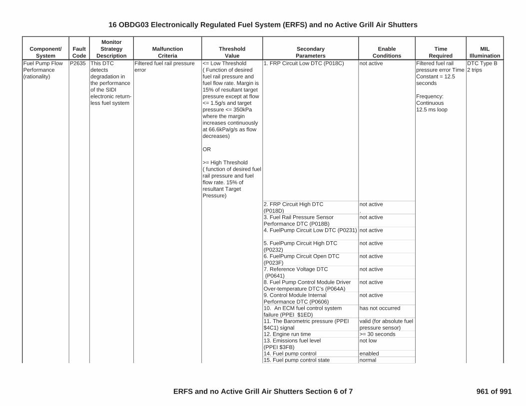
Component/System
FaultCode
MonitorStrategy
DescriptionMalfunction
CriteriaThreshold
ValueSecondaryParameters
EnableConditions
TimeRequired
MILIllumination
Fuel Pump FlowPerformance(rationality)
P2635 This DTCdetectsdegradation inthe performanceof the SIDIelectronic return-less fuel system
Filtered fuel rail pressureerror
<= Low Threshold( Function of desiredfuel rail pressure andfuel flow rate. Margin is15% of resultant targetpressure except at flow<= 1.5g/s and targetpressure <= 350kPawhere the marginincreases continuouslyat 66.6kPa/g/s as flowdecreases)
OR
>= High Threshold( function of desired fuelrail pressure and fuelflow rate. 15% ofresultant TargetPressure)
1. FRP Circuit Low DTC (P018C) not active Filtered fuel railpressure error TimeConstant = 12.5seconds
Frequency:Continuous12.5 ms loop
DTC Type B2 trips
2. FRP Circuit High DTC(P018D)
not active.
3. Fuel Rail Pressure SensorPerformance DTC (P018B)
not active
4. FuelPump Circuit Low DTC (P0231) not active
5. FuelPump Circuit High DTC(P0232)
not active
6. FuelPump Circuit Open DTC(P023F)
not active
7. Reference Voltage DTC(P0641)
not active
8. Fuel Pump Control Module DriverOver-temperature DTC’s (P064A)
not active
9. Control Module InternalPerformance DTC (P0606)
not active
10. An ECM fuel control systemfailure (PPEI $1ED)
has not occurred
11. The Barometric pressure (PPEI$4C1) signal
valid (for absolute fuelpressure sensor)
12. Engine run time >= 30 seconds13. Emissions fuel level(PPEI $3FB)
not low
14. Fuel pump control enabled15. Fuel pump control state normal
16 OBDG03 Electronically Regulated Fuel System (ERFS) and no Active Grill Air Shutters
ERFS and no Active Grill Air Shutters Section 6 of 7 961 of 991

Component/System
FaultCode
MonitorStrategy
DescriptionMalfunction
CriteriaThreshold
ValueSecondaryParameters
EnableConditions
TimeRequired
MILIllumination
16. Battery Voltage 11V<=voltage=<32V17. Fuel flow rate( See Supporting Tables tab )
> 0.047 g/sAND
<= Max allowed fuelflow rate as a functionof desired railpressure & Vbatt(Typical values in therange of 11 to 50 g/s)
18. Fuel Pressure Control System Is not responding toan over-pressurizationdue to pressure buildduring DFCO or adecreasing desiredpressure command.
Control ModuleCommunicationBus “A” Off
U0073 Detects that aCAN serial databus shortedcondition hasoccurred to forcethe CAN devicedriver to enter abus-off state
Bus Status Off Power mode Run/Crank 5 failures out of 5samples ( 5seconds)
DTC Type B2 trips
LostCommunicationWith ECM/PCM“A”
U0100 Detects thatCAN serial datacommunicationhas been lostwith the ECM
Message $0C9 Undetected 1. Power mode Run/Crank 12 failures out of 12samples (12seconds)
DTC Type B2 trips
2. Ignition Run/Crank Voltage 11V<voltage<32V3. U0073 not active
16 OBDG03 Electronically Regulated Fuel System (ERFS) and no Active Grill Air Shutters
ERFS and no Active Grill Air Shutters Section 7 of 7 962 of 991

Component/System
FaultCode
MonitorStrategy
DescriptionMalfunction
CriteriaThreshold
ValueSecondaryParameters
EnableConditions
TimeRequired
MILIllumination
Fuel RailPressure (FRP)SensorPerformance(rationality)
P018B This DTCdetects a fuelpressure sensorresponse stuckwithin the normaloperating range
Absolute value of fuelpressure change assensed during intrusivetest.
<= 30 kPa
1. FRP Circuit Low DTC(P018C) not active
Frequency:Continuous; 12.5ms loop.60 secondsbetween intrusivetests that pass
Intrusive testrequested if fuelsystem is clampedfor >= 5 seconds orfuel pressure errorvariance <=typically (0.3 to 0.6)(calculated over a2.5sec period);otherwise reportpass
DTC Type B2 trips
2. FRP Circuit High DTC(P018D) not active3. FuelPump Circuit Low DTC (P0231)
not active
Duration of intrusivetest is fuelingrelated (5 to 12seconds).
4. FuelPump Circuit High DTC(P0232)
not active
5. FuelPump Circuit Open DTC(P023F)
not active Intrusive test is runwhen fuel flow isbelow Max allowedfuel flow rate(Typical values inthe range of 11 to50 g/s)
6. Reference Voltage DTC (P0641) not active7. Fuel Pump Control Module DriverOver-temperature DTC (P064A)
not active
8. Control Module InternalPerformance DTC (P0606)
not active
9. Engine run time >=5 seconds10. Emissions fuel level(PPEI $3FB)
not low
11. Fuel pump control enabled12. Fuel pump control state normal or FRP
Rationality control13. Engine fuel flow > 0.047 g/s
16 OBDG03 Electronically Regulated Fuel System (ERFS) and standard or optional Active Grill Air Shutters
ERFS and standard or optional Active Grill Air Shutters Section 1 of 8 963 of 991

Component/System
FaultCode
MonitorStrategy
DescriptionMalfunction
CriteriaThreshold
ValueSecondaryParameters
EnableConditions
TimeRequired
MILIllumination
14. ECM fuel control system failure(PPEI $1ED)
failure has notoccurred
Fuel RailPressure (FRP)Sensor CircuitLow Voltage
P018C This DTCdetects if the fuelpressure sensorcircuit is shortedlow
FRP sensor voltage < 0.14 V
Ignition Run or Crank
72 failures out of 80samples
1 sample/12.5 ms
DTC Type B2 trips
Fuel RailPressure (FRP)Sensor CircuitHigh Voltage
P018D This DTCdetects if the fuelpressure sensorcircuit is shortedhigh
FRP sensor voltage > 4.86 V
Ignition Run or Crank
72 failures out of 80samples
1 sample/12.5 ms
DTC Type B2 trips
Fuel PumpControl CircuitLow Voltage
P0231 This DTCdetects if the fuelpump controlcircuit is shortedto low
Fuel Pump Current > 14.48A
Ignition Run or Crank
72 test failures in 80test samples if FuelPump Current<100A
DTC Type A1 trip
ORIgnition AccessoryOR 1 sample/12.5 msFuel Pump Control enabledANDIgnition Run/Crank Voltage 9V < voltage < 32V
Fuel PumpControl CircuitHigh Voltage
P0232 This DTCdetects if the fuelpump controlcircuit is shortedto high
Voltage measured at fuelpump circuit
> 3.86 V Commanded fuel pump output 0% duty cycle (off) 36 test failures in 40test samples;1 sample/12.5ms
DTC Type B2 trips
Fuel pump control enable False Pass/Faildetermination madeonly once per trip
Time that above conditions are met >=4.0 secondsFuel PumpControl Circuit(Open)
P023F This DTCdetects if the fuelpump controlcircuit is open
Fuel Pump Current <=0.5A
Ignition Run or Crank
72 test failures in 80test samples;1 sample/12.5ms
DTC Type A1 trip
AND ORFuel Pump Duty Cycle >20% Ignition Accessory
ORFuel Pump Control enabled
16 OBDG03 Electronically Regulated Fuel System (ERFS) and standard or optional Active Grill Air Shutters
ERFS and standard or optional Active Grill Air Shutters Section 2 of 8 964 of 991

Component/System
FaultCode
MonitorStrategy
DescriptionMalfunction
CriteriaThreshold
ValueSecondaryParameters
EnableConditions
TimeRequired
MILIllumination
ANDIgnition Run/Crank Voltage 9V < voltage < 32V
Fuel SystemControl ModuleEnable ControlCircuit
P025A This DTCdetects if there isa fault in the fuelpump controlenable circuit
PPEI (PPEI (PowertrainPlatform ElectricalInterface) Fuel SystemRequest ($1ED)
Fuel Pump ControlModule Enable ControlCircuit
Ignition Run or Crank
72 failures out of 80samples
1 sample/12.5 ms
DTC Type A1 trip
ANDPPEI Fuel System Request ($1ED) valid
Active Grill AirShutter "A"Performance-Stuck/ Off(Functionality)
P059F Comparecommandedshutter positionto sensedposition
Failure to achievecommanded position
Two (2) consecutiveintrusive tests fail toachieve commandedposition.
Intrusive tests aretriggered immediatelyfollowing any failure toachieve a commandedposition.
1. Power mode Run/Crank Frequency:1 sample afterevery shuttermovement.
Intrusive testrequested if shuttermovement iscommanded andposition feedbackdiffers after 19.5seconds; otherwisereport pass.
Duration of intrusivetest is shuttermovement related(40 to 120 seconds)
DTC Type B2 trips
2. Shutter Control Enabled3. Ignition Run/Crank Voltage 11V < voltage < 32V
Control ModuleRead OnlyMemory (ROM)
P0601 This DTC will bestored if anysoftware orcalibration checksum is incorrect
Calculated Checksum(CRC16)
stored checksum forany of the parts (boot,software, applicationcalibration, systemcalibration)
Ignition Run or Crank
1 failure if it occursduring the first ROMtest of the ignitioncycle, otherwise 5failures
DTC Type A1 trip
OR Frequency:Runs continuouslyin the background
Ignition AccessoryORFuel Pump Control enabled
16 OBDG03 Electronically Regulated Fuel System (ERFS) and standard or optional Active Grill Air Shutters
ERFS and standard or optional Active Grill Air Shutters Section 3 of 8 965 of 991

Component/System
FaultCode
MonitorStrategy
DescriptionMalfunction
CriteriaThreshold
ValueSecondaryParameters
EnableConditions
TimeRequired
MILIllumination
Control ModuleNot Programmed
P0602 Indicates that theFSCM needs tobe programmed
This DTC is set viacalibration, when
KeMEMD_b_NoStartCal = TRUEIgnition Run or Crank
Runs once at powerup
DTC Type A1 trip
ORIgnition AccessoryORFuel Pump Control enabled
Control ModuleLong TermMemory Reset
P0603 Non-volatilememorychecksum errorat controllerpower-up
Checksum at power-up checksum atpower-down
Ignition Run or Crank
1 failure
Frequency:Once at power-up
DTC Type A1 trip
ORIgnition AccessoryORFuel Pump Control enabled
Control ModuleRandom AccessMemory (RAM)
P0604 Indicates thatcontrol module isunable tocorrectly writeand read data toand from RAM
Data read Data written
Ignition Run or Crank
1 failure if it occursduring the first RAMtest of the ignitioncycle, otherwise 5failures
DTC Type A1 trip
OR Frequency:Ignition Accessory Runs continuously
in the background.ORFuel Pump Control enabled
Control ModuleInternalPerformance
1. MainProcessorConfigurationRegister Test
P0606
1. For all I/O configurationregister faults:
•Register contents Incorrect value. Ignition Run or Crank
Tests 1 and 21 failureFrequency:Continuously(12.5ms)
DTC Type A1 trip
ORIgnition AccessoryORFuel Pump Control enabled
This DTCindicates theFSCM hasdetected aninternalprocessor faultor externalwatchdog fault(PID 2032discriminates thesource of thefault )
16 OBDG03 Electronically Regulated Fuel System (ERFS) and standard or optional Active Grill Air Shutters
ERFS and standard or optional Active Grill Air Shutters Section 4 of 8 966 of 991

Component/System
FaultCode
MonitorStrategy
DescriptionMalfunction
CriteriaThreshold
ValueSecondaryParameters
EnableConditions
TimeRequired
MILIllumination
2. Processorclock test
2. For Processor ClockFault: •EElatch flag in EEPROM.OR
0x5A5A
1. For all I/O configuration registerfaults:•KeMEMD_b_ProcFltCfgRegEnbl TRUE
Test 33 failures out of 15samples
1 sample/12.5 ms• RAM latch flag. 0x5A 2. For Processor Clock Fault:
•KeMEMD_b_ProcFltCLKDiagEnbl TRUE
3. Externalwatchdog test
3. For External WatchdogFault:• Software control of fuelpump driver
Control Lost
3. For External Watchdog Fault:•KeFRPD_b_FPExtWDogDiagEnbl
TRUE3. For External Watchdog Fault:•Control Module ROM(P0601)
not active3. For External Watchdog Fault:•Control Module RAM(P0604)
not activeControl ModuleLong TermMemory(EEPROM)Performance
P062F Indicates that theNVM Error flaghas not beencleared
Last EEPROM write Did not complete
Ignition Run or Crank
1 test failureOnce on controllerpower-up
DTC Type B2 trips
ORIgnition AccessoryORFuel Pump Control enabled
5Volt ReferenceCircuit (ShortHigh/Low/Out ofRange)
P0641 Detectscontinuous shortor out of rangeon the #1 5Vsensor referencecircuit
Reference voltageANDOutput
>= 0.5V
inactive
Ignition Run or Crank 15 failures out of20 samples
1 sample/12.5 ms
DTC Type A1 trip
ORReference voltageANDOutput
>= 5.5V
activeORReference voltage ANDOutput
<= 4.5V
activeORReference voltage > 105% nominal (i.e.,
5.25V)OR<95% nominal(i.e., 4.75V)
16 OBDG03 Electronically Regulated Fuel System (ERFS) and standard or optional Active Grill Air Shutters
ERFS and standard or optional Active Grill Air Shutters Section 5 of 8 967 of 991

Component/System
FaultCode
MonitorStrategy
DescriptionMalfunction
CriteriaThreshold
ValueSecondaryParameters
EnableConditions
TimeRequired
MILIllumination
Fuel PumpControl Module -Driver Over-temperature 1
P064A
Pump Driver Temp > 150C Ignition Run or Crank
DTC Type B2 trips
ORIgnition AccessoryORFuel Pump Control enabledKeFRPD_b_FPOverTempDiagEnbl TRUEIgnition Run/Crank 9V<voltage<32V
Active Grille AirShutter Actuator 1Signal MessageCounter Incorrect
P151E Detects loss ofcommunicationcondition hasoccurredbetween ECUand deviceActive Grill AirShutter "A"actuator
PWM Message Undetected 1. Power mode Run/Crank Frequency: 100ms
150 failures out of167 samples
DTC Type B2 trips
2. Ignition Run/Crank Voltage 11V < voltage < 32V
Ignition 1 SwitchCircuit LowVoltage
P2534 This DTCdetects if theIgnition1 Switchcircuit is shortedto low or open
Ignition 1 voltage <= 6 V Engine Running 180 failures out of200 samples
1 sample/25.0 ms
DTC Type A1 trip
Ignition 1 SwitchCircuit HighVoltage
P2535 Detects if theIgnition1 Switchcircuit is shortedto vehicle supplyvoltage
Ignition 1 voltage > 11.7 V Ignition Run_Crank terminal Off 180 failures out of200 samples
1 sample/25.0 ms
DTC Type A1 trip
This DTCdetects if aninternal fuelpump driverovertemperaturecondition existsunder normaloperatingconditions
3 failures out of 15samples
1 sample/12.5 ms
16 OBDG03 Electronically Regulated Fuel System (ERFS) and standard or optional Active Grill Air Shutters
ERFS and standard or optional Active Grill Air Shutters Section 6 of 8 968 of 991

Component/System
FaultCode
MonitorStrategy
DescriptionMalfunction
CriteriaThreshold
ValueSecondaryParameters
EnableConditions
TimeRequired
MILIllumination
Fuel Pump FlowPerformance(rationality)
P2635 This DTCdetectsdegradation inthe performanceof the SIDIelectronic return-less fuel system
Filtered fuel rail pressureerror
<= Low Threshold( Function of desiredfuel rail pressure andfuel flow rate. Margin is15% of resultant targetpressure except at flow<= 1.5g/s and targetpressure <= 350kPawhere the marginincreases continuouslyat 66.6kPa/g/s as flowdecreases)
OR
>= High Threshold( function of desired fuelrail pressure and fuelflow rate. 15% ofresultant TargetPressure)
1. FRP Circuit Low DTC (P018C) not active Filtered fuel railpressure error TimeConstant = 12.5seconds
Frequency:Continuous12.5 ms loop
DTC Type B2 trips
2. FRP Circuit High DTC(P018D)
not active.
3. Fuel Rail Pressure SensorPerformance DTC (P018B)
not active
4. FuelPump Circuit Low DTC (P0231) not active
5. FuelPump Circuit High DTC(P0232)
not active
6. FuelPump Circuit Open DTC(P023F)
not active
7. Reference Voltage DTC(P0641)
not active
8. Fuel Pump Control Module DriverOver-temperature DTC’s (P064A)
not active
9. Control Module InternalPerformance DTC (P0606)
not active
10. An ECM fuel control systemfailure (PPEI $1ED)
has not occurred
11. The Barometric pressure (PPEI$4C1) signal
valid (for absolute fuelpressure sensor)
12. Engine run time >= 30 seconds13. Emissions fuel level(PPEI $3FB)
not low
14. Fuel pump control enabled15. Fuel pump control state normal
16 OBDG03 Electronically Regulated Fuel System (ERFS) and standard or optional Active Grill Air Shutters
ERFS and standard or optional Active Grill Air Shutters Section 7 of 8 969 of 991

Component/System
FaultCode
MonitorStrategy
DescriptionMalfunction
CriteriaThreshold
ValueSecondaryParameters
EnableConditions
TimeRequired
MILIllumination
16. Battery Voltage 11V<=voltage=<32V17. Fuel flow rate( See Supporting Tables tab )
> 0.047 g/sAND
<= Max allowed fuelflow rate as a functionof desired railpressure & Vbatt(Typical values in therange of 11 to 50 g/s)
18. Fuel Pressure Control System Is not responding toan over-pressurizationdue to pressure buildduring DFCO or adecreasing desiredpressure command.
Control ModuleCommunicationBus “A” Off
U0073 Detects that aCAN serial databus shortedcondition hasoccurred to forcethe CAN devicedriver to enter abus-off state
Bus Status Off Power mode Run/Crank 5 failures out of 5samples ( 5seconds)
DTC Type B2 trips
LostCommunicationWith ECM/PCM“A”
U0100 Detects thatCAN serial datacommunicationhas been lostwith the ECM
Message $0C9 Undetected 1. Power mode Run/Crank 12 failures out of 12samples (12seconds)
DTC Type B2 trips
2. Ignition Run/Crank Voltage 11V<voltage<32V3. U0073 not active
16 OBDG03 Electronically Regulated Fuel System (ERFS) and standard or optional Active Grill Air Shutters
ERFS and standard or optional Active Grill Air Shutters Section 8 of 8 970 of 991

P2635-Fuel Pump Performance Maximum Fuel Flow map ( grams / s )
X-axis= Desired Fuel Pressure ( kiloPascals)Y-axis= Battery voltage ( volts )
200 250 300 350 400 450 500 550 6004.5 17.5 17.5 17.5 17.5 17.5 14.8594 11.7344 8.67188 5.66406
6 17.5 17.5 17.5 17.5 17.5 14.8594 11.7344 8.67188 5.664067.5 17.5 17.5 17.5 17.5 17.5 14.8594 11.7344 8.67188 5.66406
9 17.5 17.5 17.5 17.5 17.5 14.8594 11.7344 8.67188 5.6640610.5 17.5 17.5 17.5 17.5 17.5 14.8594 11.7344 8.67188 5.66406
12 17.5 17.5 17.5 17.5 17.5 17.5 17.5 15.8438 12.765613.5 17.5 17.5 17.5 17.5 17.5 17.5 17.5 17.5 17.5
15 17.5 17.5 17.5 17.5 17.5 17.5 17.5 17.5 17.516.5 17.5 17.5 17.5 17.5 17.5 17.5 17.5 17.5 17.5
18 17.5 17.5 17.5 17.5 17.5 17.5 17.5 17.5 17.519.5 17.5 17.5 17.5 17.5 17.5 17.5 17.5 17.5 17.5
21 17.5 17.5 17.5 17.5 17.5 17.5 17.5 17.5 17.522.5 17.5 17.5 17.5 17.5 17.5 17.5 17.5 17.5 17.5
24 17.5 17.5 17.5 17.5 17.5 17.5 17.5 17.5 17.525.5 17.5 17.5 17.5 17.5 17.5 17.5 17.5 17.5 17.5
27 17.5 17.5 17.5 17.5 17.5 17.5 17.5 17.5 17.528.5 17.5 17.5 17.5 17.5 17.5 17.5 17.5 17.5 17.5
P2635-Fuel Pump Performance Filtered Pressure Error Fault Threshold High map ( kiloPascals )
X-axis= Target Fuel Pressure ( kiloPascals)Y-axis= Fuel Flow ( grams / s )
200 250 300 350 400 450 500 550 6000 30 37.5 45 52.5 60 67.5 75 82.5 90
1.5 30 37.5 45 52.5 60 67.5 75 82.5 903 30 37.5 45 52.5 60 67.5 75 82.5 90
4.5 30 37.5 45 52.5 60 67.5 75 82.5 90
16 OBDG03 Diagnostic Supporting Tables - ERFS
Diagnostic Supporting Tables - ERFS 1 of 7 971 of 991

P2635-Fuel Pump Performance Filtered Pressure Error Fault Threshold High map ( kiloPascals ) Continued….
X-axis= Target Fuel Pressure ( kiloPascals)Y-axis= Fuel Flow ( grams / s )
200 250 300 350 400 450 500 550 6006 30 37.5 45 52.5 60 67.5 75 82.5 90
7.5 30 37.5 45 52.5 60 67.5 75 82.5 909 30 37.5 45 52.5 60 67.5 75 82.5 90
10.5 30 37.5 45 52.5 60 67.5 75 82.5 9012 30 37.5 45 52.5 60 67.5 75 82.5 90
13.5 30 37.5 45 52.5 60 67.5 75 82.5 9015 30 37.5 45 52.5 60 67.5 75 82.5 90
16.5 30 37.5 45 52.5 60 67.5 75 82.5 9018 30 37.5 45 52.5 60 67.5 75 82.5 90
19.5 30 37.5 45 52.5 60 67.5 75 82.5 9021 30 37.5 45 52.5 60 67.5 75 82.5 90
22.5 30 37.5 45 52.5 60 67.5 75 82.5 9024 30 37.5 45 52.5 60 67.5 75 82.5 90
25.5 30 37.5 45 52.5 60 67.5 75 82.5 9027 30 37.5 45 52.5 60 67.5 75 82.5 90
28.5 30 37.5 45 52.5 60 67.5 75 82.5 9030 30 37.5 45 52.5 60 67.5 75 82.5 90
31.5 30 37.5 45 52.5 60 67.5 75 82.5 9033 30 37.5 45 52.5 60 67.5 75 82.5 90
34.5 30 37.5 45 52.5 60 67.5 75 82.5 9036 30 37.5 45 52.5 60 67.5 75 82.5 90
37.5 30 37.5 45 52.5 60 67.5 75 82.5 9039 30 37.5 45 52.5 60 67.5 75 82.5 90
40.5 30 37.5 45 52.5 60 67.5 75 82.5 9042 30 37.5 45 52.5 60 67.5 75 82.5 90
43.5 30 37.5 45 52.5 60 67.5 75 82.5 90
16 OBDG03 Diagnostic Supporting Tables - ERFS
Diagnostic Supporting Tables - ERFS 2 of 7 972 of 991

P2635-Fuel Pump Performance Filtered Pressure Error Fault Threshold High map ( kiloPascals ) Continued….
X-axis= Target Fuel Pressure ( kiloPascals)Y-axis= Fuel Flow ( grams / s )
200 250 300 350 400 450 500 550 60045 30 37.5 45 52.5 60 67.5 75 82.5 90
46.5 30 37.5 45 52.5 60 67.5 75 82.5 9048 30 37.5 45 52.5 60 67.5 75 82.5 90
P2635-Fuel Pump Performance Filtered Pressure Error Fault RePass Threshold High map ( kiloPascals )
X-axis= Target Fuel Pressure ( kiloPascals)Y-axis= Fuel Flow ( grams / s )
200 250 300 350 400 450 500 550 6000 25.5 31.875 38.25 44.625 51 57.375 63.75 70.125 76.5
1.5 25.5 31.875 38.25 44.625 51 57.375 63.75 70.125 76.53 25.5 31.875 38.25 44.625 51 57.375 63.75 70.125 76.5
4.5 25.5 31.875 38.25 44.625 51 57.375 63.75 70.125 76.56 25.5 31.875 38.25 44.625 51 57.375 63.75 70.125 76.5
7.5 25.5 31.875 38.25 44.625 51 57.375 63.75 70.125 76.59 25.5 31.875 38.25 44.625 51 57.375 63.75 70.125 76.5
10.5 25.5 31.875 38.25 44.625 51 57.375 63.75 70.125 76.512 25.5 31.875 38.25 44.625 51 57.375 63.75 70.125 76.5
13.5 25.5 31.875 38.25 44.625 51 57.375 63.75 70.125 76.515 25.5 31.875 38.25 44.625 51 57.375 63.75 70.125 76.5
16.5 25.5 31.875 38.25 44.625 51 57.375 63.75 70.125 76.518 25.5 31.875 38.25 44.625 51 57.375 63.75 70.125 76.5
19.5 25.5 31.875 38.25 44.625 51 57.375 63.75 70.125 76.521 25.5 31.875 38.25 44.625 51 57.375 63.75 70.125 76.5
22.5 25.5 31.875 38.25 44.625 51 57.375 63.75 70.125 76.524 25.5 31.875 38.25 44.625 51 57.375 63.75 70.125 76.5
16 OBDG03 Diagnostic Supporting Tables - ERFS
Diagnostic Supporting Tables - ERFS 3 of 7 973 of 991

P2635-Fuel Pump Performance Filtered Pressure Error Fault RePass Threshold High map ( kiloPascals ) Continued..
X-axis= Target Fuel Pressure ( kiloPascals)Y-axis= Fuel Flow ( grams / s )
200 250 300 350 400 450 500 550 60025.5 25.5 31.875 38.25 44.625 51 57.375 63.75 70.125 76.5
27 25.5 31.875 38.25 44.625 51 57.375 63.75 70.125 76.528.5 25.5 31.875 38.25 44.625 51 57.375 63.75 70.125 76.5
30 25.5 31.875 38.25 44.625 51 57.375 63.75 70.125 76.531.5 25.5 31.875 38.25 44.625 51 57.375 63.75 70.125 76.5
33 25.5 31.875 38.25 44.625 51 57.375 63.75 70.125 76.534.5 25.5 31.875 38.25 44.625 51 57.375 63.75 70.125 76.5
36 25.5 31.875 38.25 44.625 51 57.375 63.75 70.125 76.537.5 25.5 31.875 38.25 44.625 51 57.375 63.75 70.125 76.5
39 25.5 31.875 38.25 44.625 51 57.375 63.75 70.125 76.540.5 25.5 31.875 38.25 44.625 51 57.375 63.75 70.125 76.5
42 25.5 31.875 38.25 44.625 51 57.375 63.75 70.125 76.543.5 25.5 31.875 38.25 44.625 51 57.375 63.75 70.125 76.5
45 25.5 31.875 38.25 44.625 51 57.375 63.75 70.125 76.546.5 25.5 31.875 38.25 44.625 51 57.375 63.75 70.125 76.5
48 25.5 31.875 38.25 44.625 51 57.375 63.75 70.125 76.5
P2635-Fuel Pump Performance Filtered Pressure Error Fault Threshold Low map ( kiloPascals )
X-axis= Target Fuel Pressure ( kiloPascals)Y-axis= Fuel Flow ( grams / s )
200 250 300 350 400 450 500 550 6000 -260 -210 -160 -110 -60 -67.5 -75 -82.5 -90
1.5 -145 -125 -102.5 -81.25 -60 -67.5 -75 -82.5 -903 -30 -37.5 -45 -52.5 -60 -67.5 -75 -82.5 -90
4.5 -30 -37.5 -45 -52.5 -60 -67.5 -75 -82.5 -90
16 OBDG03 Diagnostic Supporting Tables - ERFS
Diagnostic Supporting Tables - ERFS 4 of 7 974 of 991

P2635-Fuel Pump Performance Filtered Pressure Error Fault Threshold Low map ( kiloPascals ) Continued…
X-axis= Target Fuel Pressure ( kiloPascals)Y-axis= Fuel Flow ( grams / s )
200 250 300 350 400 450 500 550 6006 -30 -37.5 -45 -52.5 -60 -67.5 -75 -82.5 -90
7.5 -30 -37.5 -45 -52.5 -60 -67.5 -75 -82.5 -909 -30 -37.5 -45 -52.5 -60 -67.5 -75 -82.5 -90
10.5 -30 -37.5 -45 -52.5 -60 -67.5 -75 -82.5 -9012 -30 -37.5 -45 -52.5 -60 -67.5 -75 -82.5 -90
13.5 -30 -37.5 -45 -52.5 -60 -67.5 -75 -82.5 -9015 -30 -37.5 -45 -52.5 -60 -67.5 -75 -82.5 -90
16.5 -30 -37.5 -45 -52.5 -60 -67.5 -75 -82.5 -9018 -30 -37.5 -45 -52.5 -60 -67.5 -75 -82.5 -90
19.5 -30 -37.5 -45 -52.5 -60 -67.5 -75 -82.5 -9021 -30 -37.5 -45 -52.5 -60 -67.5 -75 -82.5 -90
22.5 -30 -37.5 -45 -52.5 -60 -67.5 -75 -82.5 -9024 -30 -37.5 -45 -52.5 -60 -67.5 -75 -82.5 -90
25.5 -30 -37.5 -45 -52.5 -60 -67.5 -75 -82.5 -9027 -30 -37.5 -45 -52.5 -60 -67.5 -75 -82.5 -90
28.5 -30 -37.5 -45 -52.5 -60 -67.5 -75 -82.5 -9030 -30 -37.5 -45 -52.5 -60 -67.5 -75 -82.5 -90
31.5 -30 -37.5 -45 -52.5 -60 -67.5 -75 -82.5 -9033 -30 -37.5 -45 -52.5 -60 -67.5 -75 -82.5 -90
34.5 -30 -37.5 -45 -52.5 -60 -67.5 -75 -82.5 -9036 -30 -37.5 -45 -52.5 -60 -67.5 -75 -82.5 -90
37.5 -30 -37.5 -45 -52.5 -60 -67.5 -75 -82.5 -9039 -30 -37.5 -45 -52.5 -60 -67.5 -75 -82.5 -90
40.5 -30 -37.5 -45 -52.5 -60 -67.5 -75 -82.5 -9042 -30 -37.5 -45 -52.5 -60 -67.5 -75 -82.5 -90
43.5 -30 -37.5 -45 -52.5 -60 -67.5 -75 -82.5 -90
P2635-Fuel Pump Performance Filtered Pressure Error Fault Threshold Low map ( kiloPascals ) Continued…
16 OBDG03 Diagnostic Supporting Tables - ERFS
Diagnostic Supporting Tables - ERFS 5 of 7 975 of 991

X-axis= Target Fuel Pressure ( kiloPascals)Y-axis= Fuel Flow ( grams / s )
200 250 300 350 400 450 500 550 60045 -30 -37.5 -45 -52.5 -60 -67.5 -75 -82.5 -90
46.5 -30 -37.5 -45 -52.5 -60 -67.5 -75 -82.5 -9048 -30 -37.5 -45 -52.5 -60 -67.5 -75 -82.5 -90
P2635-Fuel Pump Performance Filtered Pressure Error Fault RePass Threshold Low map ( kiloPascals )
X-axis= Target Fuel Pressure ( kiloPascals)Y-axis= Fuel Flow ( grams / s )
200 250 300 350 400 450 500 550 6000 -221 -178.5 -136 -93.5 -51 -57.375 -63.75 -70.125 -76.5
1.5 -123.25 -106.25 -87.125 -69.063 -51 -57.375 -63.75 -70.125 -76.53 -25.5 -31.875 -38.25 -44.625 -51 -57.375 -63.75 -70.125 -76.5
4.5 -25.5 -31.875 -38.25 -44.625 -51 -57.375 -63.75 -70.125 -76.56 -25.5 -31.875 -38.25 -44.625 -51 -57.375 -63.75 -70.125 -76.5
7.5 -25.5 -31.875 -38.25 -44.625 -51 -57.375 -63.75 -70.125 -76.59 -25.5 -31.875 -38.25 -44.625 -51 -57.375 -63.75 -70.125 -76.5
10.5 -25.5 -31.875 -38.25 -44.625 -51 -57.375 -63.75 -70.125 -76.512 -25.5 -31.875 -38.25 -44.625 -51 -57.375 -63.75 -70.125 -76.5
13.5 -25.5 -31.875 -38.25 -44.625 -51 -57.375 -63.75 -70.125 -76.515 -25.5 -31.875 -38.25 -44.625 -51 -57.375 -63.75 -70.125 -76.5
16.5 -25.5 -31.875 -38.25 -44.625 -51 -57.375 -63.75 -70.125 -76.518 -25.5 -31.875 -38.25 -44.625 -51 -57.375 -63.75 -70.125 -76.5
19.5 -25.5 -31.875 -38.25 -44.625 -51 -57.375 -63.75 -70.125 -76.521 -25.5 -31.875 -38.25 -44.625 -51 -57.375 -63.75 -70.125 -76.5
22.5 -25.5 -31.875 -38.25 -44.625 -51 -57.375 -63.75 -70.125 -76.524 -25.5 -31.875 -38.25 -44.625 -51 -57.375 -63.75 -70.125 -76.5
P2635-Fuel Pump Performance Filtered Pressure Error Fault RePass Threshold Low map ( kiloPascals ) Continued…
16 OBDG03 Diagnostic Supporting Tables - ERFS
Diagnostic Supporting Tables - ERFS 6 of 7 976 of 991

X-axis= Target Fuel Pressure ( kiloPascals)Y-axis= Fuel Flow ( grams / s )
200 250 300 350 400 450 500 550 60025.5 -25.5 -31.875 -38.25 -44.625 -51 -57.375 -63.75 -70.125 -76.5
27 -25.5 -31.875 -38.25 -44.625 -51 -57.375 -63.75 -70.125 -76.528.5 -25.5 -31.875 -38.25 -44.625 -51 -57.375 -63.75 -70.125 -76.5
30 -25.5 -31.875 -38.25 -44.625 -51 -57.375 -63.75 -70.125 -76.531.5 -25.5 -31.875 -38.25 -44.625 -51 -57.375 -63.75 -70.125 -76.5
33 -25.5 -31.875 -38.25 -44.625 -51 -57.375 -63.75 -70.125 -76.534.5 -25.5 -31.875 -38.25 -44.625 -51 -57.375 -63.75 -70.125 -76.5
36 -25.5 -31.875 -38.25 -44.625 -51 -57.375 -63.75 -70.125 -76.537.5 -25.5 -31.875 -38.25 -44.625 -51 -57.375 -63.75 -70.125 -76.5
39 -25.5 -31.875 -38.25 -44.625 -51 -57.375 -63.75 -70.125 -76.540.5 -25.5 -31.875 -38.25 -44.625 -51 -57.375 -63.75 -70.125 -76.5
42 -25.5 -31.875 -38.25 -44.625 -51 -57.375 -63.75 -70.125 -76.543.5 -25.5 -31.875 -38.25 -44.625 -51 -57.375 -63.75 -70.125 -76.5
45 -25.5 -31.875 -38.25 -44.625 -51 -57.375 -63.75 -70.125 -76.546.5 -25.5 -31.875 -38.25 -44.625 -51 -57.375 -63.75 -70.125 -76.5
48 -25.5 -31.875 -38.25 -44.625 -51 -57.375 -63.75 -70.125 -76.5
16 OBDG03 Diagnostic Supporting Tables - ERFS
Diagnostic Supporting Tables - ERFS 7 of 7 977 of 991

Component/System
FaultCode
MonitorStrategy
DescriptionMalfunction
CriteriaThreshold
ValueSecondaryParameters
EnableConditions
TimeRequired
MILIllumination
Active Grill AirShutter "A"Performance-Stuck/ Off(Functionality)
P059F Comparecommandedshutter positionto sensedposition
Failure to achievecommanded position
Two (2) consecutiveintrusive tests fail toachieve commandedposition.
Intrusive tests aretriggered immediatelyfollowing any failure toachieve a commandedposition.
1. Power mode Run/Crank Frequency:1 sample afterevery shuttermovement.
Intrusive testrequested if shuttermovement iscommanded andposition feedbackdiffers after 19.5seconds; otherwisereport pass.
Duration of intrusivetest is shuttermovement related(40 to 120 seconds)
DTC Type B2 trips
2. Shutter Control Enabled3. Ignition Run/Crank Voltage 11V < voltage < 32V
Control ModuleRead OnlyMemory (ROM)
P0601 This DTC will bestored if anysoftware orcalibration checksum is incorrect
Calculated Checksum(CRC16)
stored checksum forany of the parts (boot,software, applicationcalibration, systemcalibration)
Ignition Run or Crank
1 failure if it occursduring the first ROMtest of the ignitioncycle, otherwise 5failures
DTC Type A1 trip
OR Frequency:Runs continuouslyin the background
Ignition AccessoryORFuel Pump Control enabled
Control ModuleNot Programmed
P0602 Indicates that theFSCM needs tobe programmed
This DTC is set viacalibration, when
KeMEMD_b_NoStartCal = TRUEIgnition Run or Crank
Runs once at powerup
DTC Type A1 trip
ORIgnition AccessoryORFuel Pump Control enabled
16 OBDG03 Chassis Control Module (CHCM)
Chassis Control Module (CHCM) Section 1 of 4 978 of 991
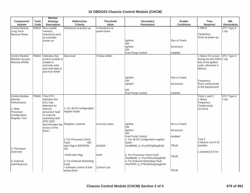
Component/System
FaultCode
MonitorStrategy
DescriptionMalfunction
CriteriaThreshold
ValueSecondaryParameters
EnableConditions
TimeRequired
MILIllumination
Control ModuleLong TermMemory Reset
P0603 Non-volatilememorychecksum errorat controllerpower-up
Checksum at power-up checksum atpower-down
Ignition Run or Crank
1 failure
Frequency:Once at power-up
DTC Type A1 trip
ORIgnition AccessoryORFuel Pump Control enabled
Control ModuleRandom AccessMemory (RAM)
P0604 Indicates thatcontrol module isunable tocorrectly writeand read data toand from RAM
Data read Data written
Ignition Run or Crank
1 failure if it occursduring the first RAMtest of the ignitioncycle, otherwise 5failures
DTC Type A1 trip
OR Frequency:Ignition Accessory Runs continuously
in the background.ORFuel Pump Control enabled
Control ModuleInternalPerformance
1. MainProcessorConfigurationRegister Test
P0606
1. For all I/O configurationregister faults:
•Register contents Incorrect value. Ignition Run or Crank
Tests 1 and 21 failureFrequency:Continuously(12.5ms)
DTC Type A1 trip
ORIgnition AccessoryORFuel Pump Control enabled
2. Processorclock test
2. For Processor ClockFault: •EElatch flag in EEPROM.OR
0x5A5A
1. For all I/O configuration registerfaults:•KeMEMD_b_ProcFltCfgRegEnbl TRUE
Test 33 failures out of 15samples
1 sample/12.5 ms• RAM latch flag. 0x5A 2. For Processor Clock Fault:
•KeMEMD_b_ProcFltCLKDiagEnbl TRUE
3. Externalwatchdog test
3. For External WatchdogFault:• Software control of fuelpump driver
Control Lost
3. For External Watchdog Fault:•KeFRPD_b_FPExtWDogDiagEnbl
TRUE
This DTCindicates theECU hasdetected aninternalprocessor faultor externalwatchdog fault(PID 2032discriminates thesource of thefault )
16 OBDG03 Chassis Control Module (CHCM)
Chassis Control Module (CHCM) Section 2 of 4 979 of 991

Component/System
FaultCode
MonitorStrategy
DescriptionMalfunction
CriteriaThreshold
ValueSecondaryParameters
EnableConditions
TimeRequired
MILIllumination
3. For External Watchdog Fault:•Control Module ROM(P0601)
not active3. For External Watchdog Fault:•Control Module RAM(P0604)
not activeControl ModuleLong TermMemory(EEPROM)Performance
P062F Indicates that theNVM Error flaghas not beencleared
Last EEPROM write Did not complete
Ignition Run or Crank
1 test failureOnce on controllerpower-up
DTC Type B2 trips
ORIgnition AccessoryORFuel Pump Control enabled
Active Grille AirShutter Actuator 1Signal MessageCounter Incorrect
P151E Detects loss ofcommunicationcondition hasoccurredbetween ECUand deviceActive Grill AirShutter "A"actuator
PWM Message Undetected 1. Power mode Run/Crank Frequency: 100ms
150 failures out of167 samples
DTC Type B2 trips
2. Ignition Run/Crank Voltage 11V < voltage < 32V
Ignition 1 SwitchCircuit LowVoltage
P2534 This DTCdetects if theIgnition1 Switchcircuit is shortedto low or open
Ignition 1 voltage <= 6 V Engine Running 180 failures out of200 samples
1 sample/25.0 ms
DTC Type A1 trip
Ignition 1 SwitchCircuit HighVoltage
P2535 Detects if theIgnition1 Switchcircuit is shortedto vehicle supplyvoltage
Ignition 1 voltage > 11.7 V Ignition Run_Crank terminal Off 180 failures out of200 samples
1 sample/25.0 ms
DTC Type A1 trip
Control ModuleCommunicationBus “A” Off
U0073 Detects that aCAN serial databus shortedcondition hasoccurred to forcethe CAN devicedriver to enter abus-off state
Bus Status Off Power mode Run/Crank 5 failures out of 5samples ( 5seconds)
DTC Type B2 trips
16 OBDG03 Chassis Control Module (CHCM)
Chassis Control Module (CHCM) Section 3 of 4 980 of 991

Component/System
FaultCode
MonitorStrategy
DescriptionMalfunction
CriteriaThreshold
ValueSecondaryParameters
EnableConditions
TimeRequired
MILIllumination
LostCommunicationWith ECM/PCM“A”
U0100 Detects thatCAN serial datacommunicationhas been lostwith the ECM
Message $0C9 Undetected 1. Power mode Run/Crank 12 failures out of 12samples (12seconds)
DTC Type B2 trips
2. Ignition Run/Crank Voltage 11V<voltage<32V3. U0073 not active
16 OBDG03 Chassis Control Module (CHCM)
Chassis Control Module (CHCM) Section 4 of 4 981 of 991

Component/System
FaultCode
MonitorStrategy
DescriptionMalfunction
CriteriaThreshold
ValueSecondaryParameters
EnableConditions
TimeRequired
MILIllumination
Fuel RailPressure (FRP)SensorPerformance(rationality)
P018B This DTCdetects a fuelpressure sensorresponse stuckwithin the normaloperating range
Absolute value of fuelpressure change assensed during intrusivetest.
<= 30 kPa
1. FRP Circuit Low DTC(P018C) Not active
Frequency:Continuous; 12.5ms loop.60 secondsbetween intrusivetests that pass
Intrusive testrequested if fuelsystem is clampedfor >= 5 seconds orfuel pressure errorvariance <=typically (0.3 to 0.6)(calculated over a2.5sec period);otherwise reportpass
DTC Type B2 trips
2. FRP Circuit High DTC(P018D) Not active3. FuelPump Circuit Low DTC (P0231)
Not active
Duration of intrusivetest is fuelingrelated (5 to 12seconds).
4. FuelPump Circuit High DTC(P0232)
Not active
5. FuelPump Circuit Open DTC(P023F)
Not active Intrusive test is runwhen fuel flow isbelow Max allowedfuel flow rate(Typical values inthe range of 11 to50 g/s)
6. Reference Voltage DTC (P0641) Not active7. Fuel Pump Control Module DriverOver-temperature DTC (P064A)
Not active
8. Control Module InternalPerformance DTC (P0606)
Not active
9. Engine run time >=5 seconds10. Emissions fuel level(PPEI $3FB)
Not low
11. Fuel pump control Enabled12. Fuel pump control state Normal or FRP
rationality control13. Engine fuel flow > 0.047 g/s
16 OBDG03 Fuel Pump Control Module (FPCM)
Fuel Pump Control Module (FPCM) Section 1 of 7 982 of 991

Component/System
FaultCode
MonitorStrategy
DescriptionMalfunction
CriteriaThreshold
ValueSecondaryParameters
EnableConditions
TimeRequired
MILIllumination
14. ECM fuel control system failure(PPEI $1ED)
Not failed
Fuel RailPressure (FRP)Sensor CircuitLow Voltage
P018C This DTCdetects if the fuelpressure sensorcircuit is shortedlow
FRP sensor voltage < 0.14 V
Ignition Run or Crank
72 failures out of 80samples
1 sample/12.5 ms
DTC Type B2 trips
Fuel RailPressure (FRP)Sensor CircuitHigh Voltage
P018D This DTCdetects if the fuelpressure sensorcircuit is shortedhigh
FRP sensor voltage > 4.86 V
Ignition Run or Crank
72 failures out of 80samples
1 sample/12.5 ms
DTC Type B2 trips
Fuel PumpControl CircuitLow Voltage
P0231 This DTCdetects if the fuelpump controlcircuit is shortedto low
Fuel Pump Current > 14.48A
Ignition Run or Crank
72 test failures in 80test samples if FuelPump Current<100A
DTC Type A1 trip
ORIgnition power mode AccessoryOR 1 sample/12.5 msFuel Pump Control enabledANDIgnition Run/Crank Voltage 9V < voltage < 32V
Fuel PumpControl CircuitHigh Voltage
P0232 This DTCdetects if the fuelpump controlcircuit is shortedto high
Voltage measured at fuelpump circuit
> 3.86 V Commanded fuel pump output 0% duty cycle (off) 36 test failures in 40test samples;1 sample/12.5ms
DTC Type B2 trips
Fuel pump control enable False Pass/Faildetermination madeonly once per trip
Time that above conditions are met >=4.0 secondsFuel PumpControl Circuit(Open)
P023F This DTCdetects if the fuelpump controlcircuit is open
Fuel Pump Current <=0.5A
Ignition Run or Crank
72 test failures in 80test samples;1 sample/12.5ms
DTC Type A1 trip
AND ORFuel Pump Duty Cycle >20% Ignition power mode Accessory
ORFuel Pump Control enabled
16 OBDG03 Fuel Pump Control Module (FPCM)
Fuel Pump Control Module (FPCM) Section 2 of 7 983 of 991
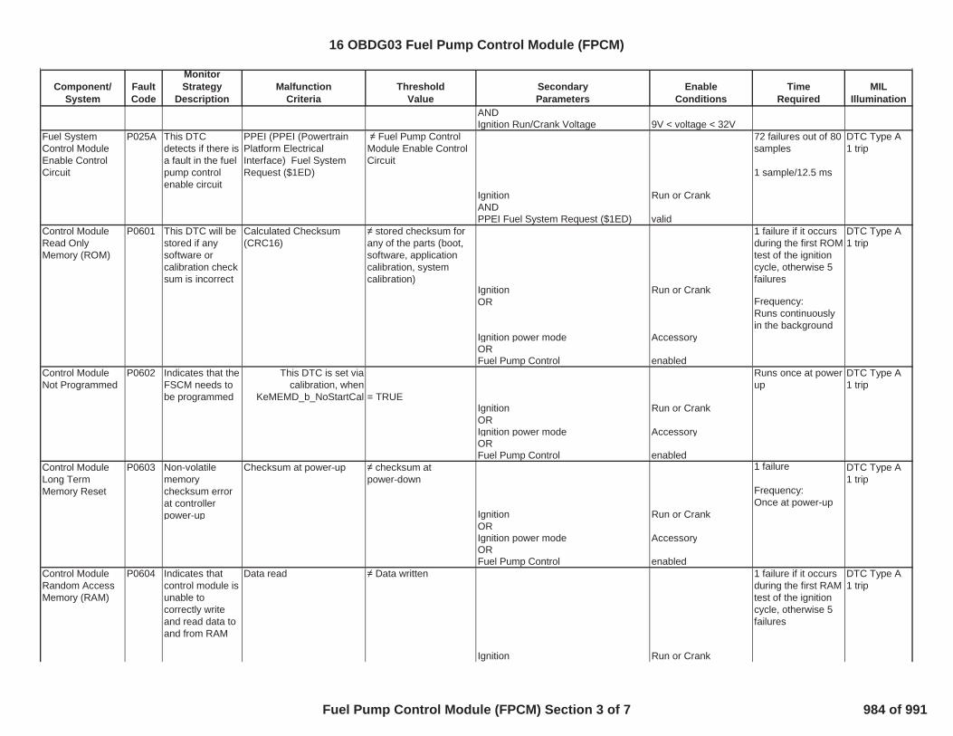
Component/System
FaultCode
MonitorStrategy
DescriptionMalfunction
CriteriaThreshold
ValueSecondaryParameters
EnableConditions
TimeRequired
MILIllumination
ANDIgnition Run/Crank Voltage 9V < voltage < 32V
Fuel SystemControl ModuleEnable ControlCircuit
P025A This DTCdetects if there isa fault in the fuelpump controlenable circuit
PPEI (PPEI (PowertrainPlatform ElectricalInterface) Fuel SystemRequest ($1ED)
Fuel Pump ControlModule Enable ControlCircuit
Ignition Run or Crank
72 failures out of 80samples
1 sample/12.5 ms
DTC Type A1 trip
ANDPPEI Fuel System Request ($1ED) valid
Control ModuleRead OnlyMemory (ROM)
P0601 This DTC will bestored if anysoftware orcalibration checksum is incorrect
Calculated Checksum(CRC16)
stored checksum forany of the parts (boot,software, applicationcalibration, systemcalibration)
Ignition Run or Crank
1 failure if it occursduring the first ROMtest of the ignitioncycle, otherwise 5failures
DTC Type A1 trip
OR Frequency:Runs continuouslyin the background
Ignition power mode AccessoryORFuel Pump Control enabled
Control ModuleNot Programmed
P0602 Indicates that theFSCM needs tobe programmed
This DTC is set viacalibration, when
KeMEMD_b_NoStartCal = TRUEIgnition Run or Crank
Runs once at powerup
DTC Type A1 trip
ORIgnition power mode AccessoryORFuel Pump Control enabled
Control ModuleLong TermMemory Reset
P0603 Non-volatilememorychecksum errorat controllerpower-up
Checksum at power-up checksum atpower-down
Ignition Run or Crank
1 failure
Frequency:Once at power-up
DTC Type A1 trip
ORIgnition power mode AccessoryORFuel Pump Control enabled
Control ModuleRandom AccessMemory (RAM)
P0604 Indicates thatcontrol module isunable tocorrectly writeand read data toand from RAM
Data read Data written
Ignition Run or Crank
1 failure if it occursduring the first RAMtest of the ignitioncycle, otherwise 5failures
DTC Type A1 trip
16 OBDG03 Fuel Pump Control Module (FPCM)
Fuel Pump Control Module (FPCM) Section 3 of 7 984 of 991
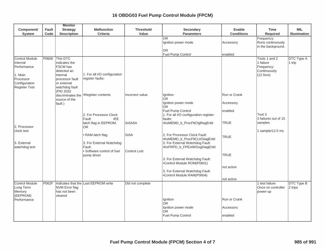
Component/System
FaultCode
MonitorStrategy
DescriptionMalfunction
CriteriaThreshold
ValueSecondaryParameters
EnableConditions
TimeRequired
MILIllumination
OR Frequency:Ignition power mode Accessory Runs continuously
in the background.ORFuel Pump Control enabled
Control ModuleInternalPerformance
1. MainProcessorConfigurationRegister Test
P0606
1. For all I/O configurationregister faults:
•Register contents Incorrect value. Ignition Run or Crank
Tests 1 and 21 failureFrequency:Continuously(12.5ms)
DTC Type A1 trip
ORIgnition power mode AccessoryORFuel Pump Control enabled
2. Processorclock test
2. For Processor ClockFault: •EElatch flag in EEPROM.OR
0x5A5A
1. For all I/O configuration registerfaults:•KeMEMD_b_ProcFltCfgRegEnbl TRUE
Test 33 failures out of 15samples
1 sample/12.5 ms• RAM latch flag. 0x5A 2. For Processor Clock Fault:
•KeMEMD_b_ProcFltCLKDiagEnbl TRUE
3. Externalwatchdog test
3. For External WatchdogFault:• Software control of fuelpump driver
Control Lost
3. For External Watchdog Fault:•KeFRPD_b_FPExtWDogDiagEnbl
TRUE3. For External Watchdog Fault:•Control Module ROM(P0601)
not active3. For External Watchdog Fault:•Control Module RAM(P0604)
not activeControl ModuleLong TermMemory(EEPROM)Performance
P062F Indicates that theNVM Error flaghas not beencleared
Last EEPROM write Did not complete
Ignition Run or Crank
1 test failureOnce on controllerpower-up
DTC Type B2 trips
ORIgnition power mode AccessoryORFuel Pump Control enabled
This DTCindicates theFSCM hasdetected aninternalprocessor faultor externalwatchdog fault(PID 2032discriminates thesource of thefault )
16 OBDG03 Fuel Pump Control Module (FPCM)
Fuel Pump Control Module (FPCM) Section 4 of 7 985 of 991

Component/System
FaultCode
MonitorStrategy
DescriptionMalfunction
CriteriaThreshold
ValueSecondaryParameters
EnableConditions
TimeRequired
MILIllumination
5Volt ReferenceCircuit (ShortHigh/Low/Out ofRange)
P0641 Detectscontinuous shortor out of rangeon the #1 5Vsensor referencecircuit
Reference voltageANDOutput
>= 0.5V
inactive
Ignition Run or Crank 15 failures out of20 samples
1 sample/12.5 ms
DTC Type A1 trip
ORReference voltageANDOutput
>= 5.5V
activeORReference voltageANDOutput
<= 4.5V
activeORReference voltage > 105% nominal (i.e.,
5.25V)OR<95% nominal(i.e., 4.75V)
Fuel PumpControl Module -Driver Over-temperature 1
P064A
Pump Driver Temp > 150C Ignition Run or Crank
DTC Type B2 trips
ORIgnition power mode AccessoryORFuel Pump Control EnabledKeFRPD_b_FPOverTempDiagEnbl TRUEIgnition Run/Crank 9V<voltage<32V
Ignition 1 SwitchCircuit LowVoltage
P2534 This DTCdetects if theIgnition1 Switchcircuit is shortedto low or open
Ignition 1 voltage <= 6 V Engine Running 180 failures out of200 samples
1 sample/25.0 ms
DTC Type A1 trip
Ignition 1 SwitchCircuit HighVoltage
P2535 Detects if theIgnition1 Switchcircuit is shortedto vehicle supplyvoltage
Ignition 1 voltage > 11.7 V Ignition Run_Crank terminal Off 180 failures out of200 samples
1 sample/25.0 ms
DTC Type A1 trip
This DTCdetects if aninternal fuelpump driverovertemperaturecondition existsunder normaloperatingconditions
3 failures out of 15samples
1 sample/12.5 ms
16 OBDG03 Fuel Pump Control Module (FPCM)
Fuel Pump Control Module (FPCM) Section 5 of 7 986 of 991
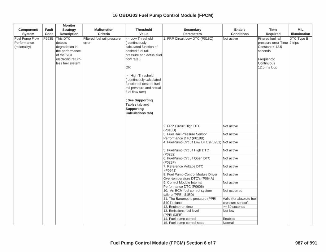
Component/System
FaultCode
MonitorStrategy
DescriptionMalfunction
CriteriaThreshold
ValueSecondaryParameters
EnableConditions
TimeRequired
MILIllumination
Fuel Pump FlowPerformance(rationality)
P2635 This DTCdetectsdegradation inthe performanceof the SIDIelectronic return-less fuel system
Filtered fuel rail pressureerror
<= Low Threshold( continuouslycalculated function ofdesired fuel railpressure and actual fuelflow rate )
OR
>= High Threshold( continuosly calculatedfunction of desired fuelrail pressure and actualfuel flow rate)
( See SupportingTables tab andSupportingCalculations tab)
1. FRP Circuit Low DTC (P018C) Not active Filtered fuel railpressure error TimeConstant = 12.5seconds
Frequency:Continuous12.5 ms loop
DTC Type B2 trips
2. FRP Circuit High DTC(P018D)
Not active.
3. Fuel Rail Pressure SensorPerformance DTC (P018B)
Not active
4. FuelPump Circuit Low DTC (P0231) Not active
5. FuelPump Circuit High DTC(P0232)
Not active
6. FuelPump Circuit Open DTC(P023F)
Not active
7. Reference Voltage DTC(P0641)
Not active
8. Fuel Pump Control Module DriverOver-temperature DTC’s (P064A)
Not active
9. Control Module InternalPerformance DTC (P0606)
Not active
10. An ECM fuel control systemfailure (PPEI $1ED)
Not occurred
11. The Barometric pressure (PPEI$4C1) signal
Valid (for absolute fuelpressure sensor)
12. Engine run time >= 30 seconds13. Emissions fuel level(PPEI $3FB)
Not low
14. Fuel pump control Enabled15. Fuel pump control state Normal
16 OBDG03 Fuel Pump Control Module (FPCM)
Fuel Pump Control Module (FPCM) Section 6 of 7 987 of 991

Component/System
FaultCode
MonitorStrategy
DescriptionMalfunction
CriteriaThreshold
ValueSecondaryParameters
EnableConditions
TimeRequired
MILIllumination
16. Battery Voltage 11V<=voltage=<32V17. Fuel flow rate( See Supporting Tables tab )
> 0.047 g/sAND
<= Max allowed fuelflow rate as a functionof desired railpressure & Vbatt(Typical values in therange of 11 to 50 g/s)
18. Fuel Pressure Control System Is not responding toan over-pressurizationdue to pressure buildduring DFCO or adecreasing desiredpressure command.
Control ModuleCommunicationBus “A” Off
U0073 Detects that aCAN serial databus shortedcondition hasoccurred to forcethe CAN devicedriver to enter abus-off state
Bus Status Off Power mode Run/Crank 5 failures out of 5samples ( 5seconds)
DTC Type B2 trips
LostCommunicationWith ECM/PCM“A”
U0100 Detects thatCAN serial datacommunicationhas been lostwith the ECM
Message $0C9 Undetected 1. Power mode Run/Crank 12 failures out of 12samples (12seconds)
DTC Type B2 trips
2. Ignition Run/Crank Voltage 11V<voltage<32V3. U0073 not active
16 OBDG03 Fuel Pump Control Module (FPCM)
Fuel Pump Control Module (FPCM) Section 7 of 7 988 of 991

P2635 - Fuel Pump Performance Maximum Fuel Flow map ( grams / second )
X-axis= Desired Fuel Pressure ( kiloPascals )Y-axis= Battery voltage ( volts )
200 250 300 350 400 450 500 550 6004.5 11.7031 11.7031 11.7031 11.7031 11.7031 11.6641 8.75781 6.07813 3.60156
6 11.7031 11.7031 11.7031 11.7031 11.7031 11.6641 8.75781 6.07813 3.601567.5 11.7031 11.7031 11.7031 11.7031 11.7031 11.6641 8.75781 6.07813 3.60156
9 11.7031 11.7031 11.7031 11.7031 11.7031 11.6641 8.75781 6.07813 3.6015610.5 11.7031 11.7031 11.7031 11.7031 11.7031 11.6641 8.75781 6.07813 3.60156
12 11.7031 11.7031 11.7031 11.7031 11.7031 11.7031 11.7031 11.7031 9.062513.5 11.7031 11.7031 11.7031 11.7031 11.7031 11.7031 11.7031 11.7031 11.7031
15 11.7031 11.7031 11.7031 11.7031 11.7031 11.7031 11.7031 11.7031 11.703116.5 11.7031 11.7031 11.7031 11.7031 11.7031 11.7031 11.7031 11.7031 11.7031
18 11.7031 11.7031 11.7031 11.7031 11.7031 11.7031 11.7031 11.7031 11.703119.5 11.7031 11.7031 11.7031 11.7031 11.7031 11.7031 11.7031 11.7031 11.7031
21 11.7031 11.7031 11.7031 11.7031 11.7031 11.7031 11.7031 11.7031 11.703122.5 11.7031 11.7031 11.7031 11.7031 11.7031 11.7031 11.7031 11.7031 11.7031
24 11.7031 11.7031 11.7031 11.7031 11.7031 11.7031 11.7031 11.7031 11.703125.5 11.7031 11.7031 11.7031 11.7031 11.7031 11.7031 11.7031 11.7031 11.7031
27 11.7031 11.7031 11.7031 11.7031 11.7031 11.7031 11.7031 11.7031 11.703128.5 11.7031 11.7031 11.7031 11.7031 11.7031 11.7031 11.7031 11.7031 11.7031
16 OBDG03 Diagnostic Supporting Tables - FPCM
Diagnostic Supporting Tables - FPCM 1 of 2 989 of 991

P2635 - Fuel Injector Flow curve ( grams / second )
X-axis= Fuel Pressure ( kiloPascals)128 148 168 188 208 228 248 268 288 308 328 348 368
2.0874 2.20142 2.31567 2.42969 2.54395 2.65796 2.77222 2.88623 3.00049 3.1145 3.22876 3.34302 3.45703
X-axis= Fuel Pressure ( kiloPascals)388 408 428 448 468 488 508 528 548 568 588 608 628
3.57129 3.63696 3.71875 3.802 3.85229 3.95288 4.08667 4.18896 4.29102 4.39307 4.49512 4.59717 4.69922
X-axis= Fuel Pressure ( kiloPascals)648 668 688 708 728 748 768
4.80127 4.90332 5.00562 5.10767 5.20972 5.31177 5.41382
P2635 - Minimum Fuel Injector Pulse Width curve ( seconds )
X-axis= engine speed ( revolutions / minute)0 512 1024 1536 2048 2560 3072 3584 4096 4608 5120 5632 6144
0.79688 0.79688 0.79688 0.79688 0.79688 0.79688 0.79688 0.79688 0.79688 0.79688 0.79688 0.79688 0.79688
X-axis= engine speed ( revolutions / minute)6656 7168 7680 8192
0.79688 0.79688 0.79688 0.79688
16 OBDG03 Diagnostic Supporting Tables - FPCM
Diagnostic Supporting Tables - FPCM 2 of 2 990 of 991

P2635 - Calculation of fault thresholds
Calculation of Fault Thresholds:
Givens: Measured values observed at a typical operating point for an 80mph roadload --Engine rpm = 1900 rev/min, Instantaneous Fuel Flow = 1.265 g/s, Fuel Line Pressure = 304
kPa (gage)
Example : Pressure Error Fault Threshold Low at chosen operating point:
Min Injector Flow [g/s] = Minimum Injector Pulse Width [ms] * Injector Slope[mg/ms/inj] * Numberof Fuel Injectors / 2 [inj/rev] * Engine Speed [rev/min] * 1/60 [min/s] * 1/1000 [g/mg]
Min Injector Flow = 0.25 * 1.565918* 4 / 2 * 1900 / 60 / 1000 = 0.0247 g/s
Max Overfueling Error [] = (Instantaneous Injector Flow [g/s] / Min Injector Flow [g/s])= 1.265 (g/s) / 0.0247 (g/s)= 51.2147 / 100 (decimal conversion)
= 0.512147 ( 51 %)
The overfuelling fuel flow error is limited to the range of between 105% and 115% overfuellingdepending on the actual fuel flow. The MaxOverfuelingError calculated above is outside the scalingrange; therefore, the overperformance fault threshold for this operating point is then calculatedusing the limited value (105% or 1.05) as follows:
Pressure Error Fault Threshold Low[kPa]= Injector Pressure Drop [kPa] *(1 -(Max Overfueling Error)^2)
= 304 * (1-(1.05 * 1.05))= -31.16 kPa
Example : Pressure Error Fault Threshold High at same given operating point as the above example:
Max Injector Flow[g/s] = Injector Slope[mg/ms/inj] * Number of Fuel Injectors [inj] * 1/1000 [g/mg]* 1000 [ms/s]
Max Injector Flow[g/s] = 1.565918 * 4 *1/1000 *1000 = 6.26 g/s
Max Underfueling Error [] = (Instantaneous Injector Flow [g/s] / Max Injector Flow [g/s])= 1.265 (g/s) / 6.26 (g/s)= 0.202 ( 20%)
The underfuelling fuel flow error is limited to the range between 85% and 95% overfuellingdepending on the actual fuel flow. The MaxUnderfuelingError calculated above falls below limitedrange, therefore it is limited to;
Max Underfueling Error [] = 0.85
The underperformance fault threshold for this operating point is then calculated as:
Pressure Error Fault Threshold High [kPa]
16 OBDG03 Diagnostic Supporting Calculations - FPCM
Diagnostic Supporting Calculations - FPCM 1 of 1 991 of 991