16-bit standard modbus technical use sheet 16bi… · sec 3120 16-bit modbus manual page 3 of 46...
TRANSCRIPT

SEC 3120 16-bit Modbus Manual Page 1 Of 46 Sensor Electronics Corporation
For Version 1.2 and above December 2012 P/N 1580282, Rev. 1, 20121228
16-bit Standard Modbus Technical Use Sheet For Version 1.2+ SEC 3120 Digital Transmitters
P/N 1580282, Rev 1, 20121228
Sensor Electronics Corporation December, 2012
Sensor Electronics Corporation 12730 Creek View Avenue
Savage, MN 55378 U.S.A.
1-952-938-9486 Tel 1-952-938-9617 Fax
1-800-285-3651 Toll Free http://www.sensorelectronics.com/
SEC 3120 16-bit Modbus Manual Page 2 Of 46 Sensor Electronics Corporation
For Version 1.2 and above December 2012 P/N 1580282, Rev. 1, 20121228
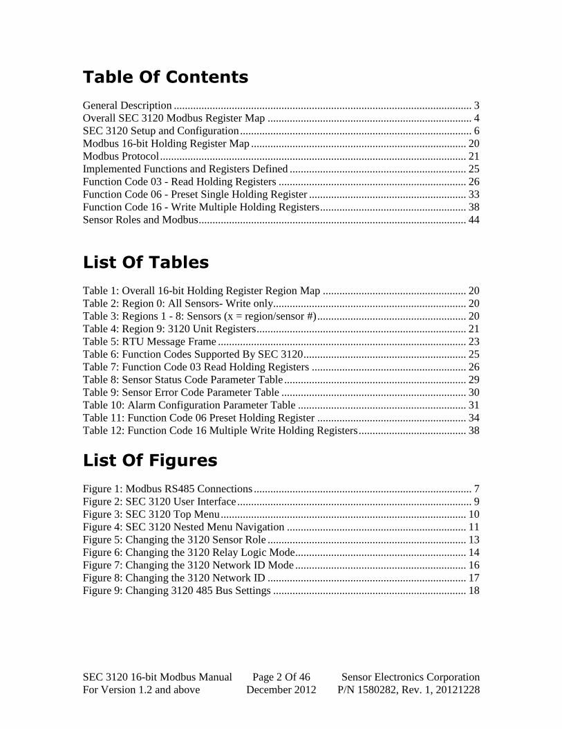
Table Of Contents
General Description ............................................................................................................ 3
Overall SEC 3120 Modbus Register Map .......................................................................... 4
SEC 3120 Setup and Configuration .................................................................................... 6
Modbus 16-bit Holding Register Map .............................................................................. 20
Modbus Protocol ............................................................................................................... 21
Implemented Functions and Registers Defined ................................................................ 25
Function Code 03 - Read Holding Registers .................................................................... 26
Function Code 06 - Preset Single Holding Register ......................................................... 33
Function Code 16 - Write Multiple Holding Registers ..................................................... 38
Sensor Roles and Modbus ................................................................................................. 44
List Of Tables
Table 1: Overall 16-bit Holding Register Region Map .................................................... 20
Table 2: Region 0: All Sensors- Write only...................................................................... 20
Table 3: Regions 1 - 8: Sensors (x = region/sensor #) ...................................................... 20
Table 4: Region 9: 3120 Unit Registers ............................................................................ 21
Table 5: RTU Message Frame .......................................................................................... 23
Table 6: Function Codes Supported By SEC 3120 ........................................................... 25
Table 7: Function Code 03 Read Holding Registers ........................................................ 26
Table 8: Sensor Status Code Parameter Table .................................................................. 29
Table 9: Sensor Error Code Parameter Table ................................................................... 30
Table 10: Alarm Configuration Parameter Table ............................................................. 31
Table 11: Function Code 06 Preset Holding Register ...................................................... 34
Table 12: Function Code 16 Multiple Write Holding Registers ....................................... 38
List Of Figures
Figure 1: Modbus RS485 Connections ............................................................................... 7
Figure 2: SEC 3120 User Interface ..................................................................................... 9
Figure 3: SEC 3120 Top Menu ......................................................................................... 10
Figure 4: SEC 3120 Nested Menu Navigation ................................................................. 11
Figure 5: Changing the 3120 Sensor Role ........................................................................ 13
Figure 6: Changing the 3120 Relay Logic Mode.............................................................. 14
Figure 7: Changing the 3120 Network ID Mode .............................................................. 16
Figure 8: Changing the 3120 Network ID ........................................................................ 17
Figure 9: Changing 3120 485 Bus Settings ...................................................................... 18

SEC 3120 16-bit Modbus Manual Page 3 Of 46 Sensor Electronics Corporation
For Version 1.2 and above December 2012 P/N 1580282, Rev. 1, 20121228
General Description
About The SEC 3120 Digital Gas Transmitter The SEC 3120 Digital Gas Transmitter is the latest generation Gas Transmitter
from Sensor Electronics Corporation, and is fully compatible
with its predecessor, the SEC 3100. The SEC 3120 Digital Gas
Transmitter allows multiple single and multi-channel SEC
sensors to be connected to it and acts as a central
communication, control, status and data logging hub for them.
While the SEC 3100 did not provide full 16-bit standard
Modbus (PI-MBUS-300 Rev. J. compliance) support, the
special SEC 3100MB16 does and is compatible with the SEC
3120 which provides full (relevant) compliance and major
feature and sensor consolidation capabilities, as well as optional sensor redundancy.
SEC 3120 Modbus Standard Supported The SEC 3120 Digital Gas Transmitter supports master mode communication as a
Modbus RTU slave. While it supports other Modbus interfaces, this document addresses
the specific 16-bit standard Modbus protocol as described in the Modicon Modbus
Specification PI-MBUS-300 Rev. J. The reader should familiarize themselves with this
document to fully understand and utilized this Modbus interface.
16-bit Modbus Supported Features and Functions Overview Functions Codes -
03 - Read Multiple Holding Registers (supported fully)
06 - Preset Single Holding Register (supported fully)
16 - Preset/Write Multiple Holding Registers (supported fully)
01 - Read Coils (not supported)
05 - Force Single Coil (not supported)
15 - Force/Write Multiple Coils (not supported)
07 - Read Exception Register (not supported)
Broadcast (Network ID 0) for all other function codes is not supported, except for
Preset (code 06) Holding Register 42920 (Listen Only Modbus Mode) and 42921
(Resume from Listen Only Modbus Mode).
All other function codes are not supported for broadcast mode in this interface.

SEC 3120 16-bit Modbus Manual Page 4 Of 46 Sensor Electronics Corporation
For Version 1.2 and above December 2012 P/N 1580282, Rev. 1, 20121228
Overall SEC 3120 Modbus Register Map Internal
Register
Modbus Holding
Register
Region Description
00000 - 01999 40001 - 42000 Reserved for coil registers- future
02000 - 02099 42001 - 42100 16-bit Sensor ALL apply region (region 0)
02100 - 02199 42101 - 42200 16-bit Sensor 1 region
02200 - 02299 42201 - 42300 16-bit Sensor 2 region
02300 - 02399 42301 - 42400 16-bit Sensor 3 region
02400 - 02499 42401 - 42500 16-bit Sensor 4 region
02500 - 02599 42501 - 42600 16-bit Sensor 5 region
02600 - 02699 42601 - 42700 16-bit Sensor 6 region
02700 - 02799 42701 - 42800 16-bit Sensor 7 region
02800 - 02899 42801 - 42900 16-bit Sensor 8 region
02900 - 02999 42901 - 43000 16-bit 3120 unit region (region 9)
03000 - 03999 43001 - 44000 Reserved for SEC HMI Legacy
04000 - 04999 44001 - 45000 Reserved for SEC HMI Legacy
05000 - 05499 45001 - 45500 Reserved for SEC 32-bit future
05500 - 05999 45501 - 46000 Reserved for SEC 32-bit future
06000 - 06999 46001 - 47000 Reserved for future use
07000 - 07499 47001 - 47500 Reserved for SEC 32-bit future
07500 - 07999 47501 - 48000 Reserved for SEC 32-bit future
08000 - 08999 48001 - 49000 Reserved for SEC HMI Advanced SID
09000 - 09998 49001 - 49999 Reserved for SEC HMI Legacy
Memory Map – 16-bit Interface Holding Registers Overview The SEC 3120 implements the 16-bit Modbus interface by breaking the address
region into ten classes (unit and sensors) and eight plus one sensor sub-regions (each
sensor region repeats the same command set with the same relative offsets) as shown
previously.
Region 0 applies a sub-set of written values to ALL logical sensors, while regions
1 – 8 apply to each individual logical sensor, and region 9 contains 3120 unit specific
(non-sensor) information. The entire 16-bit region is shown previously in green.
Within the sensor regions, the same information/register address offsets are
repeated, containing gas concentration, alarm set points, sensor status, etc. (relative
offsets 42x01 – 42x99, where x = sensor number 1 – 8).
Within the unit specific region (9), the holding register addresses are absolute (42901 =
operating status, 42902 = fault relay reason code, etc.).

SEC 3120 16-bit Modbus Manual Page 5 Of 46 Sensor Electronics Corporation
For Version 1.2 and above December 2012 P/N 1580282, Rev. 1, 20121228
Communication Parameters Protocol: Modbus RTU slave.
Baud rates: 1200, 2400, 4800, 9600, 19200 bps field selectable, Word length 8.
Parity: Odd, Even, None, field selectable.
Stop Bits: 1 or 2, field selectable.
Electrical Interface:
o RS 485, multi-drop 2-wire positive/negative (using A/B nomenclature).
o Transmit and Receive: Half Duplex.
o Useable speed will depend on cable length.
Modbus addressable: 1-247 (up to 254 if ONLY SEC 3120 units on a single bus).
Modbus Sensor Read Only Registers Gas concentration (expressed as an integer scaled up by factor) representing the
units of measurement for that specific sensor’s current gas type (PPM, % LEL,
%V/V, etc.)
Operating Status (normal, calibrating, self test, start up, in an alarm (low, mid
high) or fault
Gas category Type (toxic, hydrocarbons, oxygen, etc.)
Sensor firmware version
Sensor serial number
Alarm relay mode (trip above or below threshold, audible or normal action)
Modbus address (Network ID)
Sensor Range and Gas Factor
Sensor Status and Error code, as well as Cell Test Warn code
ASCII Gas name and Gas Units Name
Modbus Sensor Read/Write Registers Alarm thresholds (low, mid and high set points)
Zone ID (Network Zone ID)
Execute Self Test
Modbus 3120 Unit Read Only Registers Unit Operation Status
Unit Fault Relay Reason Code
Unit Serial Number
Maximum Number of Sensors That Can Be Attached
Unit Clock- Read Current Time
Unit Type
Unit Firmware Version Info

SEC 3120 16-bit Modbus Manual Page 6 Of 46 Sensor Electronics Corporation
For Version 1.2 and above December 2012 P/N 1580282, Rev. 1, 20121228
Modbus 3120 Unit Read/Write Registers Unit Clock- Write New Time Registers
Unit Clock- Set New Time Now
Unit Diagnostics Control (force relays on/off, toggle LEDs to flash)
Unit- Place into Modbus listen only mode
Unit- Restore out of Modbus listen only mode
SEC 3120 Setup and Configuration
(Bottom View of SEC 3120- Relay Board Connectors)
SEC 3120 Modbus RS-485 Network Connections Pin 5 (RS485 B) of the SEC 3120 power and communication connection block P5
is typically connected to a Modbus Master device (RX-) terminal in two-wire
connections. For the EGX-100 Gateway, this would be Pin 4 of the RS485
connection block.
Pin 4 (RS485 A) of the SEC 3120 power and communication connection block P5
is typically connected to a Modbus Master device (RX+) terminal in two-wire
connections. For the EGX-100 Gateway, this would be Pin 3 of the RS485
connection block.
The EGX-100 Gateway is connected to the Ethernet using its Ethernet port and
10/100 base T/TX cable to an Ethernet switch.
Pin1 Pin7
Pin4 Pin5
Connector Block P5

SEC 3120 16-bit Modbus Manual Page 7 Of 46 Sensor Electronics Corporation
For Version 1.2 and above December 2012 P/N 1580282, Rev. 1, 20121228
Figure 1: Modbus RS485 Connections
First Time Configuration When SEC 3120 units are first removed from the shipping container, unless
otherwise instructed upon ordering, units may arrive configured in the following modes:
1. Sensor Role: Unique- Multiple sensors can be connected having different gas
types, units of measure and ranges. This can be changed to "Identical" mode if
all attached sensors have identical gas types, ranges and units of measure, thus
allowing redundancy of measurement. It can also be changed to "Single" mode,
where only one sensor is attached to the unit in the sensor 1 connector. In "Single"
mode, the unit will ignore anything connected to the sensor 2 connector.
2. Relay Mode: OR- Sensors control the alarm relay coils in a logical "OR" fashion.
Fault relay is always controlled in a logical "OR" fashion (Any sensor fault drives
fault relay coil). The alarm relay logic mode can be changed to "AND"- forcing
both sensor's alarm status to be in agreement before the alarm relay coils are
driven (except for fault relay coil). This mode is typically used with the
"Identical" Sensor Role to provide measurement redundancy.
3. Modbus Network ID Mode: Unique- One Network ID is assigned to each
sensor, typically sensor 2 ID is greater than sensor 1 ID. These ID's can be
independently adjusted and are available on the bus and the unit will respond to
either ID for all sensors attached (Ex: Sensor 2 ID: 12, Sensor 1 ID 11). This can
be changed to "Single" mode, where all sensors are accessed through a single ID
and the IDs are identical to all sensors (Sensors 1 and 2 IDs are 5).
4. RS485 Bus Settings: SEC Default- Baud rate is 9600, stop bits are 2, parity is set
to none. This can be changed to "Alternate:"- Baud rate 9600, stop bits 1, parity
none. The bus settings may also be set to custom values, where the baud rate, stop
bits and parity are independently changed (i.e. Baud rate 19200, stop bits 1, parity
odd).
S1
S2
P5
Gateway
P5
1
2
3
4
5
1
2
3
4
5
RS485 B
RS485 A
RX-
RX+
RS
48
5
RS
48
5Re
lay
Co
nn
ec
tor

SEC 3120 16-bit Modbus Manual Page 8 Of 46 Sensor Electronics Corporation
For Version 1.2 and above December 2012 P/N 1580282, Rev. 1, 20121228
To change these settings, you must adjust them using the user interface controls
on the SEC 3120 unit. When making changes out of the box, the following order of
changes should be made (remove the unit from the communication bus until everything is
set the way you desire):
1. Sensor Role- Change the sensor role in the Network Modbus Settings menu. Save
the changes first and exit the menus before returning to make further changes.
2. Sensor Relay Mode- Change the sensor relay mode in the Relay Settings menu.
Save the changes first and exit the menus before returning to make further
changes.
3. Modbus Network Mode- Change the Modbus Network mode in the Network
Modbus Settings menu. Save the changes first and exit the menus before returning
to make further changes. Do NOT try to change the network IDs or RS485 bus
settings without exiting the menus first!
4. Modbus Network IDs- Set the Modbus Network ID(s) (Addresses based on the
network mode chosen above, using the Network Modbus ID menu. Save the
changes first and exit the menus before returning to make further changes.
5. RS485 Bus Settings- Set the RS485 Communication Settings to your desired line
settings in the Network RS485 Bus Settings Menu. Changes are applied
immediately after you choose to save them, therefore make sure these settings are
correct before connecting the unit to the bus. Make sure you have no conflicting
network IDs with any other Modbus devices on the bus.
Relevant Screens you may see in order of operation, to change the unit to the
following settings (example):
Sensor Role - Unique
Relay Logic Mode- OR
Modbus Network Mode- Single
Modbus Network IDs
RS485 Bus Settings- SEC Alternate (9600 baud, 1 stop bits, no parity)
First, we must examine how the user interface works on the 3120, is described on the
following pages:
SEC 3120 16-bit Modbus Manual Page 9 Of 46 Sensor Electronics Corporation
For Version 1.2 and above December 2012 P/N 1580282, Rev. 1, 20121228
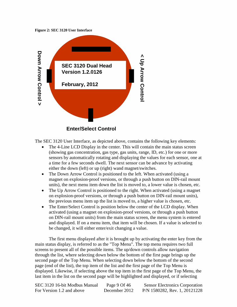
Figure 2: SEC 3120 User Interface
The SEC 3120 User Interface, as depicted above, contains the following key elements:
The 4-Line LCD Display in the center. This will contain the main status screen
(showing gas concentration, gas type, gas units, range, ID, etc.) for one or more
sensors by automatically rotating and displaying the values for each sensor, one at
a time for a few seconds dwell. The next sensor can be advance by activating
either the down (left) or up (right) wand magnet/switches.
The Down Arrow Control is positioned to the left. When activated (using a
magnet on explosion-proof versions, or through a push button on DIN-rail mount
units), the next menu item down the list is moved to, a lower value is chosen, etc.
The Up Arrow Control is positioned to the right. When activated (using a magnet
on explosion-proof versions, or through a push button on DIN-rail mount units),
the previous menu item up the list is moved to, a higher value is chosen, etc.
The Enter/Select Control is position below the center of the LCD display. When
activated (using a magnet on explosion-proof versions, or through a push button
on DIN-rail mount units) from the main status screen, the menu system is entered
and displayed. If on a menu item, that item will be chosen. If a value is selected to
be changed, it will either enter/exit changing a value.
The first menu displayed after it is brought up by activating the enter key from the
main status display, is referred to as the "Top Menu". The top menu requires two full
screens to present all of the possible items. The up/down controls allow navigation
through the list, where selecting down below the bottom of the first page brings up the
second page of the Top Menu. When selecting down below the bottom of the second
page (end of the list), the top item of the list and the first page of the Top Menu is
displayed. Likewise, if selecting above the top item in the first page of the Top Menu, the
last item in the list on the second page will be highlighted and displayed, or if selecting
SEC 3120 Dual Head
Version 1.2.0126
February, 2012
Do
wn
Arro
w C
on
trol >
< U
p A
rrow
Co
ntro
l
Enter/Select Control

SEC 3120 16-bit Modbus Manual Page 10 Of 46 Sensor Electronics Corporation
For Version 1.2 and above December 2012 P/N 1580282, Rev. 1, 20121228
above the top item of the second page then the bottom item of the first page of the Top
Menu is displayed.
This is indicated by ↑up and ↓down arrows next to the top and bottom menu items
respectively, if this kind of multi-page menu scrolling is available. Not all menus are
longer than one page, and therefore do not contain these arrow indicators.
The Top Menu is the first menu that is encountered and the last menu before
returning to the status display. Every menu item selected from the Top Menu drives
another nested menu or item that must be exited to bring the Top Menu back. Let's
examine the Top Menu:
Figure 3: SEC 3120 Top Menu
Top Menu Page 1 *↑EJECT MEMORY CARD ABORT WARMUP INFO MENU ↓MAIN MENU
Top Menu Page 2 ↑SEC DIAGNOSTICS RESET RELAYS FORMAT FLASH CARD ↓EXIT
The asterisk to the left of the menu item row indicates where the cursor is. As you
advance the cursor down the list by activating the down (left) arrow control, the asterisk
moves to indicate the newly highlighted menu item row, just as the asterisk moves up as
you activate the up (right) arrow control. When you activate the Enter/Select control, that
menu item is selected and the menu listed on that menu item row is display. This Top
Menu will be returned to the display once the newly selected menu is exited.
The purpose of the Top Menu is to place the most important, quick access items
up front to the user first. For example, if you want to eject the flash card immediately
without incurring data loss or corruption, you would select this. If you want to display
information about the SEC 3120 unit or attached sensors, you would select the
Information Menu.
To leave the Top Menu and return to the main status screen, simply scroll down to
the Exit Menu Item and select it. Menu timer time’s key activations, and once it expires
(typically 30 seconds), the menus are automatically exited and the main status screen is
re-displayed.

SEC 3120 16-bit Modbus Manual Page 11 Of 46 Sensor Electronics Corporation
For Version 1.2 and above December 2012 P/N 1580282, Rev. 1, 20121228
Figure 4: SEC 3120 Nested Menu Navigation
Shown below, is the menu navigation list. Each new menu is shown indented,
indicating that you must back out (or exit) that current menu level to return to the next
menu up:
TOP MENU PAGE 1: EJECT FLASH CARD ABORT SENSOR WARMUP INFO MENU: ABOUT 3120 UNIT ABOUT SENSORS EXIT MENU ABOUT MENU MAIN MENU: MAIN MENU PAGE 1: CONFIGURATION MENU (CALIBRATION): CONFIGURATION TOP MENU PAGE 1: SELECT SENSOR NUMBER- ZERO CALIBRATION SENSOR SPAN CALIBRATE SENSOR CHANGE CALIBRATION VALUE- CONFIGURATION TOP MENU PAGE 2: EXIT CONFIGURATION MENU ALARM CONFIGURATION TOP MENU: ALARM PAGE 1: SELECT SENSOR NUMBER- LOW ALARM SETTINGS MENU: CHANGE LOW SET POINT VALUE- CHANGE LOW ACTIVE MODE- EXIT LOW ALARM SETTINGS MENU MID ALARM SETTINGS MENU: CHANGE MID SET POINT VALUE- CHANGE MID ACTIVE MODE- EXIT MID ALARM SETTINGS MENU HIGH ALARM SETTINGS MENU: CHANGE HIGH SET POINT VALUE- CHANGE HIGH ACTIVE MODE- EXIT HIGH ALARM SETTINGS MENU ALARM PAGE 2: EXIT TOP ALARM CONFIGURATION MENU RELAY CONFIGURATION TOP MENU: RELAY PAGE 1: LOW RELAY SETTINGS MENU: LOW RELAY SETTINGS MENU PAGE 1: CHANGE LOW LATCHING MODE- CHANGE LOW ON DELAY TIME- CHANGE LOW OFF DELAY TIME- CHANGE LOW COIL ENERGIZE MODE- LOW RELAY SETTINGS MENU PAGE 2: EXIT LOW RELAY SETTINGS MENU MID RELAY SETTINGS MENU: MID RELAY SETTINGS MENU PAGE 1: CHANGE MID LATCHING MODE- CHANGE MID ON DELAY TIME- CHANGE MID OFF DELAY TIME- CHANGE MID COIL ENERGIZE MODE- MID RELAY SETTINGS MENU PAGE 2: EXIT MID RELAY SETTINGS MENU HIGH RELAY SETTINGS MENU: HIGH RELAY SETTINGS MENU PAGE 1: CHANGE HIGH LATCHING MODE- CHANGE HIGH ON DELAY TIME- CHANGE HIGH OFF DELAY TIME- CHANGE HIGH COIL ENERGIZE MODE- HIGH RELAY SETTINGS MENU PAGE 2: EXIT HIGH RELAY SETTINGS MENU FAULT RELAY SETTINGS MENU:

SEC 3120 16-bit Modbus Manual Page 12 Of 46 Sensor Electronics Corporation
For Version 1.2 and above December 2012 P/N 1580282, Rev. 1, 20121228
FAULT RELAY SETTINGS MENU PAGE 1: CHANGE FAULT LATCHING MODE- CHANGE FAULT ON DELAY TIME- CHANGE FAULT OFF DELAY TIME- CHANGE FAULT COIL ENERGIZE MODE- FAULT RELAY SETTINGS MENU PAGE 2: EXIT FAULT RELAY SETTINGS MENU RELAY PAGE 2: RELAY LOGIC MODE MENU: CHANGE RELAY LOGIC MODE-, EXIT RELAY LOGIC MODE MENU EXIT TOP RELAY CONFIGURATION MENU NETWORK TOP MENU: NETWORK ID MENU: SELECT SENSOR- CHANGE SENSOR NETWORK ID- CHANGE SENSOR NETWORK ZONE ID- EXIT NETWORK ID MENU MODBUS NETWORK MENU: MODBUS NETWORK MENU PAGE 1: CHANGE DEVICE ONLINE- CHANGE SENSOR ROLE- CHANGE NETWORK ID MODE- 485 BUS SETTINGS MENU: SELECT SEC DEFAULT SETTINGS SELECT ALTERNATE SETTINGS CUSTOM 485 LINE SETTINGS MENU: CUSTOM 485 LINE SETTINGS PAGE 1: CHANGE DATA BITS- CHANGE STOP_BITS- CHANGE PARITY MODE- CHANGE BAUD RATE- CUSTOM 485 LINE SETTINGS PAGE 2: EXIT CUSTOM 485 SETTINGS MENU EXIT 485 BUS SETTINGS MENU MODBUS NETWORK MENU PAGE 2: EXIT MODBUS NETWORK MENU EXIT NETWORK TOP MENU MAIN MENU PAGE 2: HIDE LOW GAS MENU: TOGGLE HIDE MODE ON/OFF- EXIT GAS HIDE MENU SELF TEST MENU: SELECT SENSOR- CANCEL SELF TEST MENU ABORT OPERATING SENSOR SELF TEST START SENSOR SELFT TEST DATE AND TIME MENU: CHANGE DATE: CHANGE MONTH- CHANGE DAY- CHANGE YEAR- EXIT CHANGE DATE CHANGE TIME: CHANGE HOURS- CHANGE MINUTES- CHANGE SECONDS- EXIT CHANGE TIME EXIT DATE AND TIME MENU EXIT MAIN MENU TOP MENU PAGE 2: SEC DIAGNOSTICS MENU REBOOT SYSTEM TOGGLE AND FLASH LEDS TOGGLE RELAYS ON/OFF MENU: MENU_DIAGNOSTICS_RLY_TOGGLE_t, MENU_TOGGLE_LOW, MENU_TOGGLE_MID, MENU_TOGGLE_HI, MENU_TOGGLE_FAULT,

SEC 3120 16-bit Modbus Manual Page 13 Of 46 Sensor Electronics Corporation
For Version 1.2 and above December 2012 P/N 1580282, Rev. 1, 20121228
MENU_DIAGNOSTICS_RLY_TOGGLE_2, MENU_TOGGLE_EXIT, EXIT SEC DIAGNOSTICS MENU RESET LATCHED RELAYS FORMAT FLASH CARD EXIT TOP MENU
Note: When changes are made to values, a "Save or Abort Changes" message is
displayed forcing you to choose to save the changes or discard them before the previous
menu is displayed. If you want to make the changes permanent, choose "Save", if you are
not sure, then choose "Abort":
Save or Abort Changes Popup * SAVE CHANGES ABORT CHANGES Figure 5: Changing the 3120 Sensor Role
After entering the menu system, choose the Main Menu:
Top Menu 1 ↑EJECT MEMORY CARD ABORT WARMUP INFO MENU *↓MAIN MENU
Top Menu 2 ↑SEC DIAGNOSTICS RESET RELAYS FORMAT FLASH CARD ↓EXIT
Then choose the Network Menu:
Main Menu 1 ↑CALIBRATION ALARM RELAY *↓NETWORK
Main Menu 2 ↑HIDE LOW GAS SELF TEST SET DATE TIME ↓PREVIOUS MENU

SEC 3120 16-bit Modbus Manual Page 14 Of 46 Sensor Electronics Corporation
For Version 1.2 and above December 2012 P/N 1580282, Rev. 1, 20121228
Then choose the Modbus Settings Menu:
Network Top Menu NETWORK ID MENU * MODBUS SETTINGS PREVIOUS MENU
Then highlight the Sensors Item and activate enter:
Modbus Settings Menu 1 ↑ONLINE YES * SENSORS UNIQUE * NET ID SINGLE ↓485 BUS MENU
Modbus Settings Menu 2 ↓PREVIOUS MENU
Activate the left/right up/down controls until "Unique" (for our example) is
shown. Notice the asterisk to the right of the mode- this indicates the value that is
changing and that the up/down controls now effect choosing a value up/down. When the
correct choice shows, active enter again and the asterisk to the right will disappear. Scroll
down the menu and choose "Previous Menu" to back out of the Modus Settings menu,
then choose "Previous Menu" to exit the Network Menu (which will bring up the Save or
Abort confirmation), then scroll down to and choose the "Previous Menu" item and exit
the Main Menu, then scroll down to "Exit" and press enter to return to the Main Status
Display.
Figure 6: Changing the 3120 Relay Logic Mode
After entering the menu system, choose the Main Menu:
Top Menu 1 ↑EJECT MEMORY CARD ABORT WARMUP INFO MENU *↓MAIN MENU
Top Menu 2 ↑SEC DIAGNOSTICS RESET RELAYS FORMAT FLASH CARD ↓EXIT

SEC 3120 16-bit Modbus Manual Page 15 Of 46 Sensor Electronics Corporation
For Version 1.2 and above December 2012 P/N 1580282, Rev. 1, 20121228
Then choose the Relay Settings Menu:
Main Menu 1 ↑CALIBRATION ALARM * RELAY ↓NETWORK
Main Menu 2 ↑HIDE LOW GAS SELF TEST SET DATE TIME ↓PREVIOUS MENU
Then scroll down to and choose the Relay Logic Mode Menu:
Relay Top Menu 1 ↑LOW MID HIGH ↓FAULT
Relay Top Menu 2 *↑LOGIC MODE ↓PREVIOUS MENU
Then use the up/down keys to select the desired mode:
Relay Logic Mode Menu * MODE AND * PREVIOUS MENU
Change the item to "OR" (for our example). Notice the asterisk to the right
disappears. Now scroll down and choose the "Previous Menu" item to return to the Relay
Settings menu (which will bring up the Save or Abort confirmation). Scroll down to and
choose the "Previous Menu" item to return to the Main Menu. Then scroll down to and
choose the "Previous Menu" item to return to the Top Menu. Then scroll down to and
choose the "Exit" item to return back to the Main Status screen.
SEC 3120 16-bit Modbus Manual Page 16 Of 46 Sensor Electronics Corporation
For Version 1.2 and above December 2012 P/N 1580282, Rev. 1, 20121228
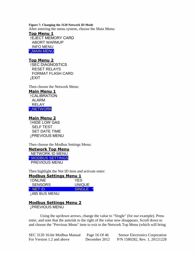
Figure 7: Changing the 3120 Network ID Mode
After entering the menu system, choose the Main Menu:
Top Menu 1 ↑EJECT MEMORY CARD ABORT WARMUP INFO MENU *↓MAIN MENU
Top Menu 2 ↑SEC DIAGNOSTICS RESET RELAYS FORMAT FLASH CARD ↓EXIT
Then choose the Network Menu:
Main Menu 1 ↑CALIBRATION ALARM RELAY *↓NETWORK
Main Menu 2 ↑HIDE LOW GAS SELF TEST SET DATE TIME ↓PREVIOUS MENU
Then choose the Modbus Settings Menu:
Network Top Menu NETWORK ID MENU * MODBUS SETTINGS PREVIOUS MENU
Then highlight the Net ID item and activate enter:
Modbus Settings Menu 1 ↑ONLINE YES SENSORS UNIQUE * NET ID SINGLE * ↓485 BUS MENU
Modbus Settings Menu 2 ↓PREVIOUS MENU
Using the up/down arrows, change the value to "Single" (for our example). Press
enter, and note that the asterisk to the right of the value now disappears. Scroll down to
and choose the "Previous Menu" item to exit to the Network Top Menu (which will bring

SEC 3120 16-bit Modbus Manual Page 17 Of 46 Sensor Electronics Corporation
For Version 1.2 and above December 2012 P/N 1580282, Rev. 1, 20121228
up the Save or Abort confirmation). Scroll down to and choose the "Previous Menu" item
to exit to the Main Menu. Scroll down to and choose the "Previous Menu" item to exit to
the Top Menu. Scroll down to and choose the "Exit" menu item to exit the menu system
and return back to the Main Status Screen.
Figure 8: Changing the 3120 Network ID
After entering the menu system, choose the Main Menu:
Top Menu 1 ↑EJECT MEMORY CARD ABORT WARMUP INFO MENU *↓MAIN MENU
Top Menu 2 ↑SEC DIAGNOSTICS RESET RELAYS FORMAT FLASH CARD ↓EXIT
Then choose the Network Menu:
Main Menu 1 ↑CALIBRATION ALARM RELAY *↓NETWORK
Main Menu 2 ↑HIDE LOW GAS SELF TEST SET DATE TIME ↓PREVIOUS MENU
Then choose the Network ID Menu:
Network Top Menu * NETWORK ID MENU MODBUS SETTINGS PREVIOUS MENU
Then highlight the Network ID item and activate enter (in single sensor role, you
cannot change the sensor number so this item cannot be highlighted and the ID should be
selected automatically first):
Network ID Menu FOR SENSOR: ONE * ID 12 * ZONE 4 PREVIOUS MENU

SEC 3120 16-bit Modbus Manual Page 18 Of 46 Sensor Electronics Corporation
For Version 1.2 and above December 2012 P/N 1580282, Rev. 1, 20121228
Using the up/down controls, change the ID value to the desired value. Activate
enter. You may also change the Zone value as well. If you are not in Single Sensor Role,
you may also scroll up and change the sensor number to TWO and repeat the process if
you are choosing to set different network IDs.
Once you are done, scroll down and choose the "Previous Menu" item to exit to
the Network Top Menu. Scroll down and choose the "Previous Menu" item to exit to the
Main Menu (which will bring up the Save or Abort confirmation). Scroll down to and
choose the "Previous Menu" item to exit to the Top Menu. Scroll down to and choose the
"Exit" menu item to exit and return back to the Main Status Screen.
Figure 9: Changing 3120 485 Bus Settings
After entering the menu system, choose the Main Menu:
Top Menu 1 ↑EJECT MEMORY CARD ABORT WARMUP INFO MENU *↓MAIN MENU
Top Menu 2 ↑SEC DIAGNOSTICS RESET RELAYS FORMAT FLASH CARD ↓EXIT
Then choose the Network Menu:
Main Menu 1 ↑CALIBRATION ALARM RELAY *↓NETWORK
Main Menu 2 ↑HIDE LOW GAS SELF TEST SET DATE TIME ↓PREVIOUS MENU
Then choose the Modbus Settings Menu:
Network Top Menu NETWORK ID MENU * MODBUS SETTINGS PREVIOUS MENU

SEC 3120 16-bit Modbus Manual Page 19 Of 46 Sensor Electronics Corporation
For Version 1.2 and above December 2012 P/N 1580282, Rev. 1, 20121228
Then highlight the 485 Bus menu and activate enter:
Modbus Settings Menu 1 ↑ONLINE YES SENSORS UNIQUE NET ID SINGLE *↓485 BUS MENU
Modbus Settings Menu 2 ↓PREVIOUS MENU
Scroll down to and choose "Comm-Alternate" to change from stop bits of 2 to 1
while preserving all other SEC default settings. Press enter, and all of the bus values will
be displayed.
485 Bus Settings Menu COMM-DEFAULT * COMM-ALTERNATE COMM-CUSTOM PREVIOUS MENU
The values will be displayed for all parameters, and when you are done viewing
them, press enter to return to the 485 Bus Settings menu. Scroll down to and choose the
"Previous Menu" item (which will bring up the Save or Abort confirmation) to exit and
return to the Modbus Settings menu. Scroll down to and choose the "Previous Menu"
item to exit and return to the Network Top Menu. Scroll down to and choose the
"Previous Menu" item (which will bring up the Save or Abort confirmation) to exit and
return to the Main Menu. Scroll down to and choose the "Previous Menu" item to exit
and return to the Top Menu. Scroll down to and choose the "Exit" menu item to exit and
return to the Main Status Screen.
Place the unit on your bus when you are properly configured and ready to test.
Navigate through the menus to the Network Menu, Modbus Settings Menu and make sure
that the device is set to be "Online".
You may use a Modbus Master device on the bus (such as the WEB interface of a
Schneider EGX gateway) or a PC running ModSCan32 to read the network ID by
choosing the network ID of the 3120 device, choosing holding register 42110, 1 item.
The value read back should be the same value as the network ID.
SEC 3120 16-bit Modbus Manual Page 20 Of 46 Sensor Electronics Corporation
For Version 1.2 and above December 2012 P/N 1580282, Rev. 1, 20121228
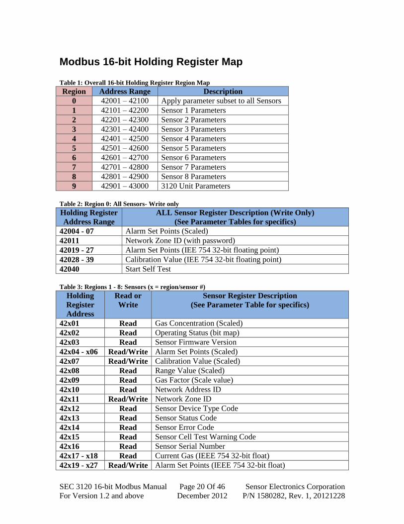
Modbus 16-bit Holding Register Map Table 1: Overall 16-bit Holding Register Region Map
Region Address Range Description
0 42001 – 42100 Apply parameter subset to all Sensors
1 42101 – 42200 Sensor 1 Parameters
2 42201 – 42300 Sensor 2 Parameters
3 42301 – 42400 Sensor 3 Parameters
4 42401 – 42500 Sensor 4 Parameters
5 42501 – 42600 Sensor 5 Parameters
6 42601 – 42700 Sensor 6 Parameters
7 42701 – 42800 Sensor 7 Parameters
8 42801 – 42900 Sensor 8 Parameters
9 42901 – 43000 3120 Unit Parameters
Table 2: Region 0: All Sensors- Write only
Holding Register
Address Range
ALL Sensor Register Description (Write Only)
(See Parameter Tables for specifics)
42004 - 07 Alarm Set Points (Scaled)
42011 Network Zone ID (with password)
42019 - 27 Alarm Set Points (IEE 754 32-bit floating point)
42028 - 39 Calibration Value (IEE 754 32-bit floating point)
42040 Start Self Test
Table 3: Regions 1 - 8: Sensors (x = region/sensor #)
Holding
Register
Address
Read or
Write
Sensor Register Description
(See Parameter Table for specifics)
42x01 Read Gas Concentration (Scaled)
42x02 Read Operating Status (bit map)
42x03 Read Sensor Firmware Version
42x04 - x06 Read/Write Alarm Set Points (Scaled)
42x07 Read/Write Calibration Value (Scaled)
42x08 Read Range Value (Scaled)
42x09 Read Gas Factor (Scale value)
42x10 Read Network Address ID
42x11 Read/Write Network Zone ID
42x12 Read Sensor Device Type Code
42x13 Read Sensor Status Code
42x14 Read Sensor Error Code
42x15 Read Sensor Cell Test Warning Code
42x16 Read Sensor Serial Number
42x17 - x18 Read Current Gas (IEEE 754 32-bit float)
42x19 - x27 Read/Write Alarm Set Points (IEEE 754 32-bit float)

SEC 3120 16-bit Modbus Manual Page 21 Of 46 Sensor Electronics Corporation
For Version 1.2 and above December 2012 P/N 1580282, Rev. 1, 20121228
Holding
Register
Address
Read or
Write
Sensor Register Description
(See Parameter Table for specifics)
42x28 -x 30 Read/Write Calibration Value (IEEE 754 32-bit float)
42x31 -x32 Read Sensor Range (IEEE 754 32-bit float)
42x33 Read Alarm Configuration (bit map)
42x34 - x37 Read Gas Name (ASCII characters eight, 1st left to right)
42x38 - x39 Read Gas Units Name (ASCII characters four, 1st left to right)
42x40 Write Only Start Self Test (with password)
Table 4: Region 9: 3120 Unit Registers
Holding
Register
Address
Read or
Write
3120 Unit Register Description
(See Parameter Table for specifics)
42901 Read Unit Operating Status (bit map)
42902 - 03 Read Fault Relay Reason Code (32-bit bit map)
42904 - 05 Read Unit Serial Number (32-bit integer)
42906 - 11 Read Clock Read Registers (real-time)
42912 - 17 Write Only Clock Write Registers (New write hold registers)
42918 Write Only Set Clock from New Clock write hold registers
42919 Write Only Diagnostics (force alarm/fault relays, force LED blinking)
42920 Write Only Set Unit into Listen Only Modbus Mode
42921 Write Only Restore Unit back from Listen Only Modbus Mode
42922 Read Maximum number of sensors that can be attached
42923 Read Unit Type Code
42924 - 25 Read Unit Firmware Version (2- words for major.minor.build)
Modbus Protocol
Introducing Modbus Protocol Modbus communication is based on a master–slave technique, in which only one
device (the master) can initiate transactions (queries). The other devices (the slaves)
respond by supplying the requested data to the master, or by taking the action requested
in the query. The master can address individual slaves or can initiate a broadcast message
to all slaves. Slaves return a message (a response) to queries that are addressed to them
individually. Responses are not returned to broadcast queries from the master.
The Modbus protocol establishes the format for the master’s query by placing the
device (or broadcast) address, a function code defining the requested action, any data to
be sent and an error-checking field into the message. The slave’s response message is
also constructed using Modbus protocol. The response contains fields confirming the
action taken, any data to be returned and an error-checking field. If an error occurred in
receipt of the message, or if the slave is unable to perform the requested action, the slave
will construct an error message and send it as the response.

SEC 3120 16-bit Modbus Manual Page 22 Of 46 Sensor Electronics Corporation
For Version 1.2 and above December 2012 P/N 1580282, Rev. 1, 20121228
The Query–Response Cycle
Query Message from Master
Response Message from Slave
The Query: The function code in the query tells the addressed slave device which
kind of action to perform. The data bytes contain any additional information that the
slave will need to perform the function. For example, function code 03 will query the
slave to read holding registers and respond with their contents. The data field must
contain the information telling the slave which register to start at and how many registers
to read. The error check field provides a method for the slave to validate the integrity of
the message contents.
The Response: If the slave makes a normal response, the function code in the
response is an echo of the function code in the query. The data bytes contain the data
collected by the slave, such as register values or status. If an error occurs, the function
code is modified to indicate that the response is an error response, and the data bytes
contain a code that describes the error. The error check field allows the master to confirm
that the message contents are valid.
RTU Modbus Message Framing In RTU serial transmission mode, a Modbus message is placed by the transmitting
device into a frame that has a known beginning and ending point. This allows receiving
devices to begin at the start of the message, read the address portion, determine which
device is addressed (or all devices, if the message is broadcast) and know when the
message is completed. Partial messages can be detected and errors can be set as a result.
In RTU mode, messages start with a silent interval of at least 3.5 character times.
This is most easily implemented as a multiple of character times at the baud rate that is
being used on a network (shown as T1-T2-T3-T4 in Table 5). The first field then
transmitted is the device address.
The allowable characters transmitted for all fields are hexadecimal 0-9, A-F.
Networked devices monitor the network bus continuously, including during the “silent”
intervals. When the first field (the address field) is received, each device decodes it to
determine if it is the addressed device.
Device Address
Function Code
8-bit Data Bytes
Error Check
Device Address
Function Code
8-bit Data Bytes
Error Check

SEC 3120 16-bit Modbus Manual Page 23 Of 46 Sensor Electronics Corporation
For Version 1.2 and above December 2012 P/N 1580282, Rev. 1, 20121228
Following the last transmitted character, a silent interval of at least 3.5 character
times marks the end of the message. A new message can begin after this interval.
The entire message frame must be transmitted as a continuous stream. If a silent
interval of more than 1.5 character times occurs before completion of the frame, the
receiving device flushes the incomplete message and assumes that the next byte will be
the address field of a new message.
Similarly, if a new message begins earlier than 3.5 character times following a
previous message, the receiving device will consider it a continuation of the previous
message. This will set an error, as the value in the final CRC field will not be valid for
the combined messages. A typical message is shown below:
Table 5: RTU Message Frame
Start Address Function Data CRC Check End
T1-T2-T3-T4 8 Bits 8 Bits n x Bits
(high byte
to low byte)
16 Bits
(low byte then
high byte)
T1-T2-T3-T4
The address field of a message frame contains eight bits (RTU). Valid slave
devices are assigned addresses in the range of 1–247 (if only SEC 3120 devices are on
this bus slave addressed may go up to 254). A master addresses a slave by placing the
slave address in the address field of the message. When the slave sends its response, it
places its own address in the address field of the response to let the master know which
slave is responding.
Address 0 is used for the broadcast address, which all slave devices recognize.
The function code field of a message frame contains eight bits (RTU). For the
SEC 3120, valid codes are 1, 3, 5, 6, 15 and 16 (although holding register ranges are
currently only established for codes 3, 6, and 16).
When a message is sent from a master to a slave device, the function code field
tells the slave what kind of action to perform. When the slave responds to the master, it
uses the function code field to indicate either a normal (error-free) response or that some
kind of error occurred (called an exception response). For a normal response, the slave
simply echoes the original function code. For an exception response, the slave returns a
code that is equivalent to the original function code with its most significant bit set to
logic 1.
In addition to its modification of the function code for an exception response, the
slave places a unique code into the data field of the response message. This tells the
master what kind of error occurred or the reason for the exception.
The master device’s application program has the responsibility of handling
exception responses. Typical responses are to post subsequent retries of the message, to
try diagnostic messages to the slave and to notify operators.

SEC 3120 16-bit Modbus Manual Page 24 Of 46 Sensor Electronics Corporation
For Version 1.2 and above December 2012 P/N 1580282, Rev. 1, 20121228
The data field of messages sent from a master to slave devices contains additional
information that the slave must use to take the action defined by the function code. This
can include items such as discrete and register addresses, the quantity of items to be
handled and the count of actual data bytes in the field.
For example, if the master requests a slave to read a group of holding registers
(function code 03), the data field specifies the starting register and how many registers
are to be read.
If no error occurs, the data field of a response from a slave to a master contains
the data requested. If an error occurs, the field contains an exception code that the master
application can use to determine the next action to be taken.
The data field can be nonexistent (of zero length) in certain kinds of messages.
CRC Error Checking In RTU mode, messages include an error-checking field that is based on a
Cyclical Redundancy Check (CRC) method. The CRC field checks the contents of the
entire message. It is applied regardless of any parity check method used for the individual
characters of the message.
The CRC field is 2 bytes, containing a 16-bit binary value. The CRC value is
calculated by the transmitting device, which appends the CRC to the message. The
receiving device recalculates a CRC during receipt of the message and compares the
calculated value to the actual value it received in the CRC field. If the two values are not
equal, an error results. The CRC algorithm uses a polynomial of Hexadecimal A001:
1. Load a 16–bit register with FFFF hex (all 1’s). Call this the CRC register.
2. Exclusive OR the first 8–bit byte of the message with the low–order byte of the
16–bit CRC register, putting the result in the CRC register.
3. Shift the CRC register one bit to the right (toward the LSB), zero–filling the
MSB. Extract and examine the LSB.
4. (If the LSB was 0): Repeat Step 3 (another shift).
(If the LSB was 1): Exclusive OR the CRC register with the polynomial value
A001 hex (1010 0000 0000 0001).
5. Repeat Steps 3 and 4 until 8 shifts have been performed. When this is done, a
complete 8–bit byte will have been processed.
6. The CRC register now contains the check value to be appended to (or compared
to the received message check value) the end of the message, low 8-bit CRC byte
followed by the high 8-bit CRC byte.

SEC 3120 16-bit Modbus Manual Page 25 Of 46 Sensor Electronics Corporation
For Version 1.2 and above December 2012 P/N 1580282, Rev. 1, 20121228
Implemented Functions and Registers Defined
The function code identifies the command being issued to the device. It is one
byte in length and has a value of 1, 3, 5, 6, 15 or 16.
Table 6: Function Codes Supported By SEC 3120
Function Code Description
1 Read Coil Status Registers (not supported)
3 Read Holding Registers
5 Force Single Coil Register (not supported)
6 Preset Single Holding Register
15 Force Multiple Coil Registers (not supported)
16 Preset Multiple Holding Registers
For the current 16-bit version, registers are only mapped for function codes 3, 6,
and 16. Otherwise an exception response will be generated.
In most cases, there is no response for a query that contains an invalid slave
address, invalid CRC data or a non-supported broadcast mode, etc. In some cases, the
unit might issue an Exception 2 as an error response if an invalid register address is
requested for a valid function code. However, if invalid function code is issued, such as
function 07 were transmitted, then an Exception 1 message would be generated to
indicate that the function code is not supported.
Query Coil Status Message
Field Name Example (Hex)
Slave Address 01
Function Code 03
Address High 01
Address Low 5B
Num Points High 00
Num Points Low 03
CRC Low Byte 75
CRC High Byte E4
Response Exception 2
Field Name Example (Hex)
Slave Address 01
Function Code 83
Exception Code 02
CRC Low Byte C0
CRC High Byte F1

SEC 3120 16-bit Modbus Manual Page 26 Of 46 Sensor Electronics Corporation
For Version 1.2 and above December 2012 P/N 1580282, Rev. 1, 20121228
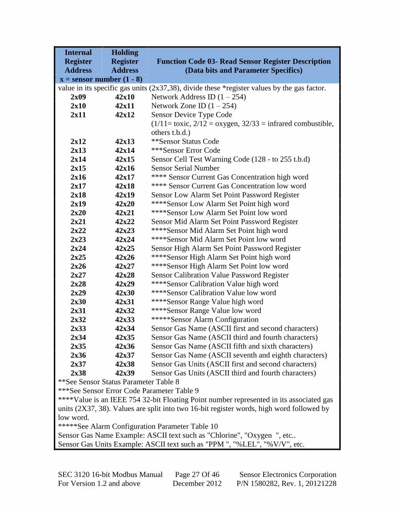
Function Code 03 - Read Holding Registers The following holding registers (4X references) are supported by the SEC 3120
for one or multiple sequential function code 03 read 16-bit binary operations (multiple
read operations must be sequential starting at the specified valid holding register address
in the read list). Broadcast mode is not supported for this function.
Table 7: Function Code 03 Read Holding Registers
Internal
Register
Address
Holding
Register
Address
Function Code 03- Read Sensor Register Description
(Data bits and Parameter Specifics)
x = sensor number (1 - 8)
2x00 42x01 *Scaled Sensor Gas Concentration
2x01 42x02 Bit-mapped Sensor Operating Status:
Bit 0,1: alarm status (0,0 = no alarm, 0,1 = low
alarm, 1,0 = mid alarm, 1,1 = high alarm.
Bit 2: fault alarm status (1 = fault, 0 = no)
Bit 3: self test (1 = testing, 0 = not)
Bit 4: cell test warning (1 = have warning, 0 = no)
Bit 5: init/warm (1 = init/startup, 0 = idle/run)
Bit 6: sensor missing (1 = missing, 0 = ok)
Bit 7: calibration (1 = calibrating, 0 = not)
Bit 8 - 15: **Sensor Status Code (8 bit integer)
2x02 42x03 Sensor Firmware Version (1 – 255)
2x03 42x04 *Scaled Low Sensor Alarm Set Point
2x04 42x05 *Scaled Mid Sensor Alarm Set Point
2x05 42x06 *Scaled High Sensor Alarm Set Point
2x06 42x07 *Scaled Sensor Calibration Value
2x07 42x08 *Scaled Sensor Range Value
2x08 42x09 Sensor Gas Factor
*These registers are scaled by Sensor Gas Factor (2x08). To obtain the real floating point
Query Exception Status Message
Field Name Example (Hex)
Slave Address 11
Function Code 07
CRC Low Byte 4C
CRC High Byte 22
Response Exception 1
Field Name Example (Hex)
Slave Address 11
Function Code 87
Exception Code 01
CRC Low Byte 83
CRC High Byte F5
SEC 3120 16-bit Modbus Manual Page 27 Of 46 Sensor Electronics Corporation
For Version 1.2 and above December 2012 P/N 1580282, Rev. 1, 20121228
Internal
Register
Address
Holding
Register
Address
Function Code 03- Read Sensor Register Description
(Data bits and Parameter Specifics)
x = sensor number (1 - 8)
value in its specific gas units (2x37,38), divide these *register values by the gas factor.
2x09 42x10 Network Address ID (1 – 254)
2x10 42x11 Network Zone ID (1 – 254)
2x11 42x12 Sensor Device Type Code
(1/11= toxic, 2/12 = oxygen, 32/33 = infrared combustible,
others t.b.d.)
2x12 42x13 **Sensor Status Code
2x13 42x14 ***Sensor Error Code
2x14 42x15 Sensor Cell Test Warning Code (128 - to 255 t.b.d)
2x15 42x16 Sensor Serial Number
2x16 42x17 **** Sensor Current Gas Concentration high word
2x17 42x18 **** Sensor Current Gas Concentration low word
2x18 42x19 Sensor Low Alarm Set Point Password Register
2x19 42x20 ****Sensor Low Alarm Set Point high word
2x20 42x21 ****Sensor Low Alarm Set Point low word
2x21 42x22 Sensor Mid Alarm Set Point Password Register
2x22 42x23 ****Sensor Mid Alarm Set Point high word
2x23 42x24 ****Sensor Mid Alarm Set Point low word
2x24 42x25 Sensor High Alarm Set Point Password Register
2x25 42x26 ****Sensor High Alarm Set Point high word
2x26 42x27 ****Sensor High Alarm Set Point low word
2x27 42x28 Sensor Calibration Value Password Register
2x28 42x29 ****Sensor Calibration Value high word
2x29 42x30 ****Sensor Calibration Value low word
2x30 42x31 ****Sensor Range Value high word
2x31 42x32 ****Sensor Range Value low word
2x32 42x33 *****Sensor Alarm Configuration
2x33 42x34 Sensor Gas Name (ASCII first and second characters)
2x34 42x35 Sensor Gas Name (ASCII third and fourth characters)
2x35 42x36 Sensor Gas Name (ASCII fifth and sixth characters)
2x36 42x37 Sensor Gas Name (ASCII seventh and eighth characters)
2x37 42x38 Sensor Gas Units (ASCII first and second characters)
2x38 42x39 Sensor Gas Units (ASCII third and fourth characters)
**See Sensor Status Parameter Table 8
***See Sensor Error Code Parameter Table 9
****Value is an IEEE 754 32-bit Floating Point number represented in its associated gas
units (2X37, 38). Values are split into two 16-bit register words, high word followed by
low word.
*****See Alarm Configuration Parameter Table 10
Sensor Gas Name Example: ASCII text such as "Chlorine", "Oxygen ", etc..
Sensor Gas Units Example: ASCII text such as "PPM ", "%LEL", "%V/V", etc.
SEC 3120 16-bit Modbus Manual Page 28 Of 46 Sensor Electronics Corporation
For Version 1.2 and above December 2012 P/N 1580282, Rev. 1, 20121228
Internal
Register
Address
Holding
Register
Address
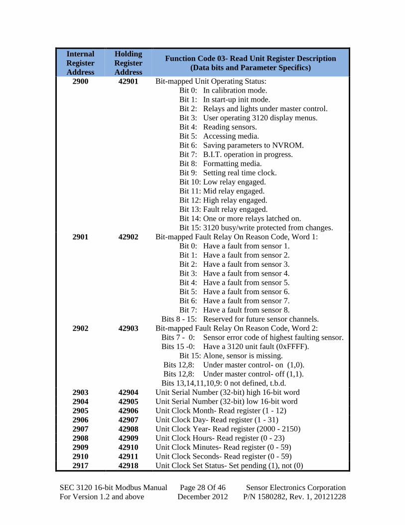
Function Code 03- Read Unit Register Description
(Data bits and Parameter Specifics)
2900 42901 Bit-mapped Unit Operating Status:
Bit 0: In calibration mode.
Bit 1: In start-up init mode.
Bit 2: Relays and lights under master control.
Bit 3: User operating 3120 display menus.
Bit 4: Reading sensors.
Bit 5: Accessing media.
Bit 6: Saving parameters to NVROM.
Bit 7: B.I.T. operation in progress.
Bit 8: Formatting media.
Bit 9: Setting real time clock.
Bit 10: Low relay engaged.
Bit 11: Mid relay engaged.
Bit 12: High relay engaged.
Bit 13: Fault relay engaged.
Bit 14: One or more relays latched on.
Bit 15: 3120 busy/write protected from changes.
2901 42902 Bit-mapped Fault Relay On Reason Code, Word 1:
Bit 0: Have a fault from sensor 1.
Bit 1: Have a fault from sensor 2.
Bit 2: Have a fault from sensor 3.
Bit 3: Have a fault from sensor 4.
Bit 4: Have a fault from sensor 5.
Bit 5: Have a fault from sensor 6.
Bit 6: Have a fault from sensor 7.
Bit 7: Have a fault from sensor 8.
Bits 8 - 15: Reserved for future sensor channels.
2902 42903 Bit-mapped Fault Relay On Reason Code, Word 2:
Bits 7 - 0: Sensor error code of highest faulting sensor.
Bits 15 -0: Have a 3120 unit fault (0xFFFF).
Bit 15: Alone, sensor is missing.
Bits 12,8: Under master control- on (1,0).
Bits 12,8: Under master control- off (1,1).
Bits 13,14,11,10,9: 0 not defined, t.b.d.
2903 42904 Unit Serial Number (32-bit) high 16-bit word
2904 42905 Unit Serial Number (32-bit) low 16-bit word
2905 42906 Unit Clock Month- Read register (1 - 12)
2906 42907 Unit Clock Day- Read register (1 - 31)
2907 42908 Unit Clock Year- Read register (2000 - 2150)
2908 42909 Unit Clock Hours- Read register (0 - 23)
2909 42910 Unit Clock Minutes- Read register (0 - 59)
2910 42911 Unit Clock Seconds- Read register (0 - 59)
2917 42918 Unit Clock Set Status- Set pending (1), not (0)

SEC 3120 16-bit Modbus Manual Page 29 Of 46 Sensor Electronics Corporation
For Version 1.2 and above December 2012 P/N 1580282, Rev. 1, 20121228
Internal
Register
Address
Holding
Register
Address
Function Code 03- Read Unit Register Description
(Data bits and Parameter Specifics)
2921 42922 Maximum number of sensors that can be attached
(Allows master to determine if device is a SEC 3100MB16,
which only supports one sensor, or an advanced transmitter
such as the SEC 3120 which supports at least two sensors)
2922 42923 Unit Type Code (0x0100 or 256 decimal)- SEC
3100MB16, (0x0101 or 257 decimal)- SEC 3120 Dual
Sensor, (0x0111 or 273 decimal)- SEC 3120 supporting
multiple logical sub-channels, other values TBD...
2923 42924 Unit Firmware Version Word 1 (Major version- MSB {0 -
255}, Minor version- LSB {0 - 255})
2924 42925 Unit Firmware Version Word 2 (Revision/Build number-
16-bit build number increment, 0 - 65535)
Table 8: Sensor Status Code Parameter Table
Value (Hex) Description
0000 Sensor is running, normal mode. All is well, OK.
0001 Not used.
0002 Sensor Zero Calibrating.
0003 Sensor Span Calibrating.
0004 Sensor 4-20ma Calibrating.
0005 Sensor in Warm-up.
0006 Sensor in Power Up Fault.
0007 Sensor in Calibration Fault.
0008 Sensor in Span Fault.
0009 Sensor in Unit Fault.
000A Sensor in Optics Fault.
000B Sensor in Zero Drift Fault.
000C Sensor in Configuration Fault.
000D Sensor in Hot Zero Calibration.
000E Sensor in Cool Zero Calibration.
000F Sensor in Self Test Operation.
0010 Sensor in Reference Channel Fault.
0011 Sensor in Active Channel Fault.
0012 Sensor in Power Fault.
0013 - 00FF Other values t.b.d.
SEC 3120 16-bit Modbus Manual Page 30 Of 46 Sensor Electronics Corporation
For Version 1.2 and above December 2012 P/N 1580282, Rev. 1, 20121228
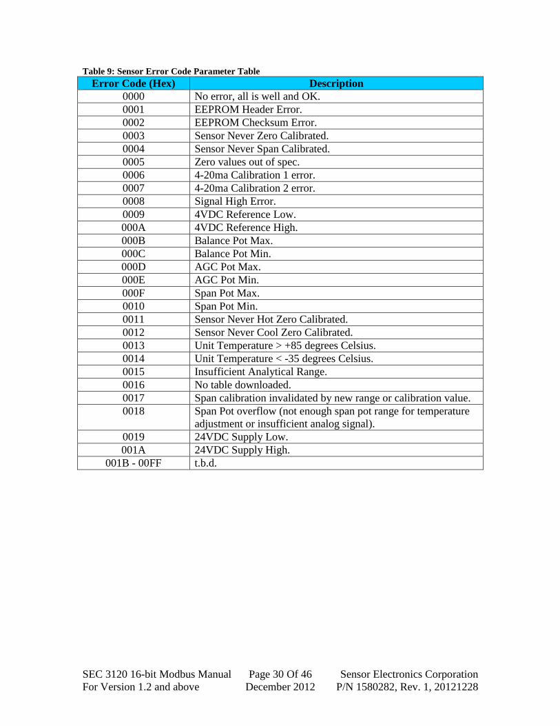
Table 9: Sensor Error Code Parameter Table
Error Code (Hex) Description
0000 No error, all is well and OK.
0001 EEPROM Header Error.
0002 EEPROM Checksum Error.
0003 Sensor Never Zero Calibrated.
0004 Sensor Never Span Calibrated.
0005 Zero values out of spec.
0006 4-20ma Calibration 1 error.
0007 4-20ma Calibration 2 error.
0008 Signal High Error.
0009 4VDC Reference Low.
000A 4VDC Reference High.
000B Balance Pot Max.
000C Balance Pot Min.
000D AGC Pot Max.
000E AGC Pot Min.
000F Span Pot Max.
0010 Span Pot Min.
0011 Sensor Never Hot Zero Calibrated.
0012 Sensor Never Cool Zero Calibrated.
0013 Unit Temperature > +85 degrees Celsius.
0014 Unit Temperature < -35 degrees Celsius.
0015 Insufficient Analytical Range.
0016 No table downloaded.
0017 Span calibration invalidated by new range or calibration value.
0018 Span Pot overflow (not enough span pot range for temperature
adjustment or insufficient analog signal).
0019 24VDC Supply Low.
001A 24VDC Supply High.
001B - 00FF t.b.d.

SEC 3120 16-bit Modbus Manual Page 31 Of 46 Sensor Electronics Corporation
For Version 1.2 and above December 2012 P/N 1580282, Rev. 1, 20121228
Table 10: Alarm Configuration Parameter Table
Bit Field Description
Bit 0 Low alarm relay normally energized (1) or not (0).
Bit 1 Low alarm relay latching mode enabled (1) or not (0).
Bit 2 Low alarm relay audible alarm mode enabled (2) or not (0).
Bit 3 Low alarm on when gas is above low set point (1) or below (0).
Bit 4 Mid alarm relay normally energized (1) or not (0).
Bit 5 Mid alarm relay latching mode enabled (1) or not (0).
Bit 6 Mid alarm relay audible alarm mode enabled (2) or not (0).
Bit 7 Mid alarm on when gas is above mid set point (1) or below (0).
Bit 8 High alarm relay normally energized (1) or not (0).
Bit 9 High alarm relay latching mode enabled (1) or not (0).
Bit 10 High alarm relay audible alarm mode enabled (2) or not (0).
Bit 11 High alarm on w/gas above high set point (1) or below (0).
Bit 12 Fault alarm relay normally energized (1) or not (0).
Bit 13 Fault alarm relay latching mode enabled (1) or not (0).
Bit 14 Fault alarm relay audible alarm mode enabled (2) or not (0).
Bit 15 Fault alarm on when fault code for sensor non-zero (always 0).
Read Holding Registers Query The query message specifies the starting register and quantity of registers to be
read. SEC 3120 internal registers are addressed starting at zero: Modbus holding registers
1–16 are addressed as 0–15.
Multiple sensors are allowed to be attached to a single 3120 unit; therefore the
register map is split into regions as shown previously in Table 1. Each sensor has its own
region (a repetition of the same parameter registers that address each specific sensor's
parameters), and each region is a multiple of 100, as expressed by its sensor number (i.e.
sensor 1 - region 1, or internal register 21xx, sensor 2 - region 2, or internal register
22xx).
Region 0 is reserved for write-only for applying changes to all sensors, therefore
Region 0 (internal registers 20xx) cannot be read.
Region 9 is reserved for SEC 3120 unit level information rather than sensor
specific information. Region 9 (internal registers 29xx) can be read. The maximum
number of sensors that may be attached to the transmitter can be queried from internal
registers 2921. This will allow the master to determine if the other regions apply (region
0, 2-8) if it returns a one indicating that it is an SEC 3100MB16 device, or an advanced
transmitter such as the SEC 3120 (returning two or more).
Note: An SEC 3120 configure as "Single Sensor" mode, will return a one
indicating that only regions 1 and 9 are accessible- requests to read regions outside of this
range (2 - 8 or 0) will generate exception 2 messages.

SEC 3120 16-bit Modbus Manual Page 32 Of 46 Sensor Electronics Corporation
For Version 1.2 and above December 2012 P/N 1580282, Rev. 1, 20121228
Here is an example of a request to read Modbus holding registers 42104–42106
from slave device 17, sensor 1 (region 1 = 21xx):
Response The register data in the response message are packed as two bytes per register,
with the binary contents right justified within each byte. For each register, the first byte
contains the high order bits, and the second byte contains the low order bits.
Here is an example of a response to the query:
The contents of register 42104 are shown as the two byte values of 01 2A hex or
298 decimal. The contents of registers 42105 and 42106 are 01 8F and 03 21 hex, or 399
and 801 decimal, respectively.
Read Holding Register Response
Field Name Example (Hex)
Slave Address 11
Function Code 03
Byte Count 06
Data High Byte (Register 42104) 01
Data Low Byte (Register 42104) 2A
Data High Byte (Register 42105) 01
Data Low Byte (Register 42105) 8F
Data High Byte (Register 42106) 03
Data High Byte (Register 42106) 21
CRC Low Byte 04
CRC High Byte 5D
Read Holding Register Query
Field Name Example (Hex)
Slave Address 11
Function Code 03
Starting Address High 08
Starting Address Low 37
Num Points High 00
Num Points Low 03
CRC Low Byte B4
CRC High Byte F5

SEC 3120 16-bit Modbus Manual Page 33 Of 46 Sensor Electronics Corporation
For Version 1.2 and above December 2012 P/N 1580282, Rev. 1, 20121228
SEC 3120 units support 40+ holding registers for each sensor attached, as well as
an additional 12+ holding registers specific to the 3120 unit head itself as listed in Table
7.
If a starting address is not within the range shown in Table 7, the SEC 3120 unit
will issue an Exception 2 as a response. If the number of points is too many, the SEC
3120 may issue an Exception 3 as a response.
Note: SCAN MODE: A crucial feature of the SEC 3120 16-bit Modbus implementation
is that it enables a Modbus Master to gain one or more holding register contents at a
time. This allows the master to start at any legal holding register address and retrieve in
one scan block, an entire set of relevant parameters for a given sensor, such as Gas
Concentration, Operating Status and Alarm Set Points or more in one read query
operation.
Function Code 06 - Preset Single Holding Register
Description Presets a value into a single holding register (4x references). Modbus allows a
broadcast mode with function presets to the same register reference in all attached slaves,
however the SEC 3120 supports multiple sensors attached to a single unit, hence
broadcast mode is not allowed, except for one preset register pair 42920 (listen only
mode) and 42921 (restore from listen only mode).
To accomplish the same functionality as a broadcast to the same preset reference
in the SEC 3120, so long as the sensors attached are truly identical, region 0 of the
holding register map (holding register address range 42001 - 42099) may be used. If
written to the same relative offsets as the sensor regions (i.e. 42004 for 42x04, 42005 for
42x05, where x = specific sensor number) then the values written to region 0 registers
will apply as if written to all sensor relative region offset registers.
The advantage of using a preset function is that it does not have the overhead of
an item count or a byte count. It is a very small packet targeted at changing one very
specific 16-bit register with a full read-back of the contents to ensure proper
communication.
Response Exception 2
Field Name Example (Hex)
Slave Address 01
Function Code 83
Exception Code 02
CRC Low Byte C0
CRC High Byte F1
Response Exception 3
Field Name Example (Hex)
Slave Address 01
Function Code 83
Exception Code 03
CRC Low Byte 01
CRC High Byte 31
SEC 3120 16-bit Modbus Manual Page 34 Of 46 Sensor Electronics Corporation
For Version 1.2 and above December 2012 P/N 1580282, Rev. 1, 20121228
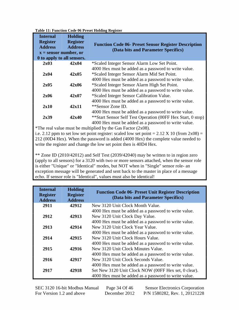
Table 11: Function Code 06 Preset Holding Register
Internal
Register
Address
Holding
Register
Address Function Code 06- Preset Sensor Register Description
(Data bits and Parameter Specifics) x = sensor number, or
0 to apply to all sensors.
2x03 42x04 *Scaled Integer Sensor Alarm Low Set Point.
4000 Hex must be added as a password to write value.
2x04 42x05 *Scaled Integer Sensor Alarm Mid Set Point.
4000 Hex must be added as a password to write value.
2x05 42x06 *Scaled Integer Sensor Alarm High Set Point.
4000 Hex must be added as a password to write value.
2x06 42x07 *Scaled Integer Sensor Calibration Value.
4000 Hex must be added as a password to write value.
2x10 42x11 **Sensor Zone ID.
4000 Hex must be added as a password to write value.
2x39 42x40 **Start Sensor Self Test Operation (00FF Hex Start, 0 stop)
4000 Hex must be added as a password to write value.
*The real value must be multiplied by the Gas Factor (2x08).
i.e. 2.12 ppm to set low set point register: scaled low set point = 2.12 X 10 (from 2x08) =
212 (00D4 Hex). When the password is added (4000 Hex) the complete value needed to
write the register and change the low set point then is 40D4 Hex.
** Zone ID (2010/42012) and Self Test (2039/42040) may be written to in region zero
(apply to all sensors) for a 3120 with two or more sensors attached, when the sensor role
is either "Unique" or "Identical" modes, but NOT when in "Single" sensor role- an
exception message will be generated and sent back to the master in place of a message
echo. If sensor role is "Identical", values must also be identical!
Internal
Register
Address
Holding
Register
Address
Function Code 06- Preset Unit Register Description
(Data bits and Parameter Specifics)
2911 42912 New 3120 Unit Clock Month Value.
4000 Hex must be added as a password to write value.
2912 42913 New 3120 Unit Clock Day Value.
4000 Hex must be added as a password to write value.
2913 42914 New 3120 Unit Clock Year Value.
4000 Hex must be added as a password to write value.
2914 42915 New 3120 Unit Clock Hours Value.
4000 Hex must be added as a password to write value.
2915 42916 New 3120 Unit Clock Minutes Value.
4000 Hex must be added as a password to write value.
2916 42917 New 3120 Unit Clock Seconds Value.
4000 Hex must be added as a password to write value.
2917 42918 Set New 3120 Unit Clock NOW (00FF Hex set, 0 clear).
4000 Hex must be added as a password to write value.

SEC 3120 16-bit Modbus Manual Page 35 Of 46 Sensor Electronics Corporation
For Version 1.2 and above December 2012 P/N 1580282, Rev. 1, 20121228
Internal
Register
Address
Holding
Register
Address
Function Code 06- Preset Unit Register Description
(Data bits and Parameter Specifics)
2918 42919 Bit-mapped Diagnostics Force Coils And Toggle LEDs.
Bit 0: Force low relay coil (1 = on, 0 = off)
Bit 1: Force mid relay coil (1 = on, 0 = off)
Bit 2: Force high relay coil (1 = on, 0 = off)
Bit 3: Force fault relay coil (1 = on, 0 = off)
Bit 4: Toggle LEDs red/green ( 1 = on, 0 = off)
Duration of force will be approximately 30 seconds unless
re-written.
4000 Hex must be added as a password to write value.
2919 42920 Modbus Listen Only (00FF engages). No response will be
given and unit will not respond to any commands addresses
to it or broadcast, other than command to restore from
listen only (2920).
4000 Hex must be added as a password to write value.
2920 42921 Modbus Restore From Listen Only (00FF engages).
Response will be given and unit will resume responding to
commands addresses to it or broadcast.
4000 Hex must be added as a password to write value.
The SEC 3120 supports sensor preset holding registers as shown in table 11
previously. To avoid accidentally writing to any of these registers, 4000 hex (16384
decimal) must be added to the register value as a password. Parameter registers low, mid,
and high alarm set points and calibration value must be less than the full scale (range) of
measurement. For example, if the range of measurement is 2000 ppm for Chlorine, then
to set 1200 ppm as the high alarm set point, the value of register 42x06 should be 44B0
hex (17584 decimal).
The normal response is an echo of the query, returned after the register contents
have been preset.

SEC 3120 16-bit Modbus Manual Page 36 Of 46 Sensor Electronics Corporation
For Version 1.2 and above December 2012 P/N 1580282, Rev. 1, 20121228
Query The query message specifies the register reference to be preset. Registers are
addressed starting at zero: register 1 is addressed as 0.
Here is an example of a request to preset register 42106 to set high alarm set point
as 1200 in slave device 17, for sensor 1:
The normal response is an echo of the query, returned after the register contents
have been preset.
Response Here is an example of a response to the query shown above:
Preset ALL Sensor High Set Point
Holding Registers Response
Field Name Example (Hex)
Slave Address 11
Function Code 06
Address High 07
Address Low D5
Data High 44
Data Low B0
CRC Low Byte A9
CRC High Byte 62
Preset One Sensor High Set Point
Holding Register Response
Field Name Example (Hex)
Slave Address 11
Function Code 06
Address High 08
Address Low 39
Data High 44
Data Low B0
CRC Low Byte 6B
CRC High Byte 83
Preset ALL Sensor High Set Point
Holding Registers Query
Field Name Example (Hex)
Slave Address 11
Function Code 06
Address High 07
Address Low D5
Data High 44
Data Low B0
CRC Low Byte A9
CRC High Byte 62
Preset One Sensor High Set Point
Holding Register Query
Field Name Example (Hex)
Slave Address 11
Function Code 06
Address High 08
Address Low 39
Data High 44
Data Low B0
CRC Low Byte 6B
CRC High Byte 83

SEC 3120 16-bit Modbus Manual Page 37 Of 46 Sensor Electronics Corporation
For Version 1.2 and above December 2012 P/N 1580282, Rev. 1, 20121228
If the register address in the query shown previously is not valid for a preset
register function, the SEC 3120 unit will issue an Exception 2 as a response. If the preset
data in the query does not include the password, the SEC 3120 unit will issue an
Exception 8 as a response. If the SEC 3120 unit is not operating in identical sensor role
mode (for setting threshold values), it will generate an Exception 3 response.
Response Exception 2
Field Name Example (Hex)
Slave Address 01
Function Code 86
Exception Code 02
CRC Low Byte C3
CRC High Byte A1
Response Exception 3
Field Name Example (Hex)
Slave Address 01
Function Code 86
Exception Code 03
CRC Low Byte 02
CRC High Byte 61
Response Exception 8
Field Name Example (Hex)
Slave Address 01
Function Code 86
Exception Code 08
CRC Low Byte 43
CRC High Byte A6

SEC 3120 16-bit Modbus Manual Page 38 Of 46 Sensor Electronics Corporation
For Version 1.2 and above December 2012 P/N 1580282, Rev. 1, 20121228
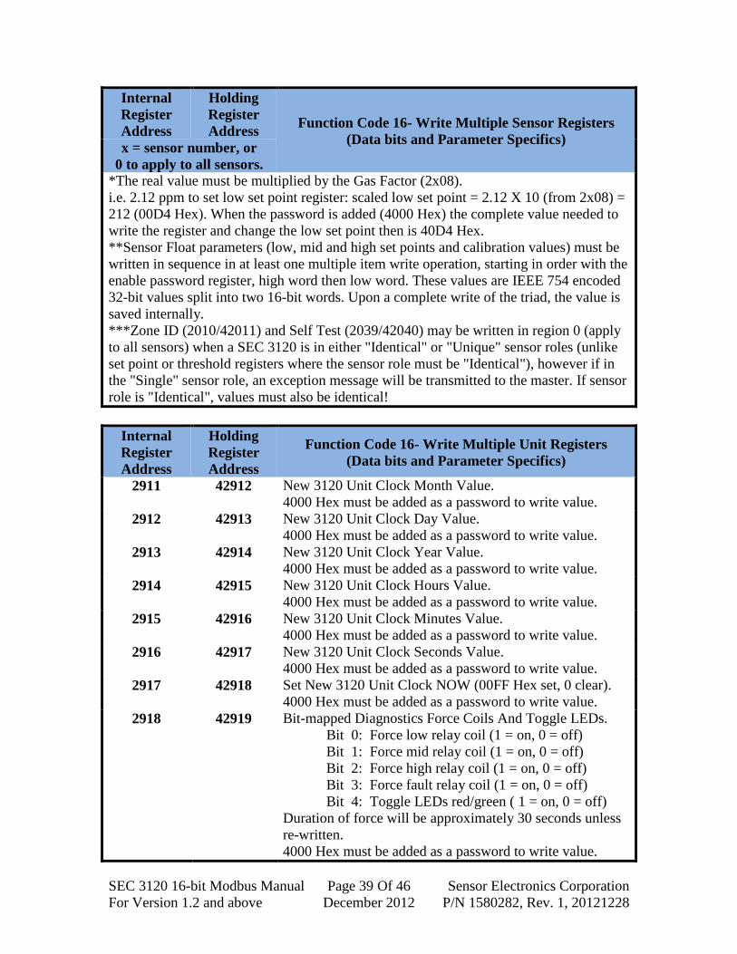
Function Code 16 - Write Multiple Holding Registers
Description Writes a set of values into one or more sequential holding registers (4x
references). Modbus does NOT allow a broadcast mode with this function code.
Table 12: Function Code 16 Multiple Write Holding Registers
Internal
Register
Address
Holding
Register
Address Function Code 16- Write Multiple Sensor Registers
(Data bits and Parameter Specifics) x = sensor number, or
0 to apply to all sensors.
2x03 42x04 *Scaled Integer Sensor Alarm Low Set Point.
4000 Hex must be added as a password to write value.
2x04 42x05 *Scaled Integer Sensor Alarm Mid Set Point.
4000 Hex must be added as a password to write value.
2x05 42x06 *Scaled Integer Sensor Alarm High Set Point.
4000 Hex must be added as a password to write value.
2x06 42x07 *Scaled Integer Sensor Calibration Value.
4000 Hex must be added as a password to write value.
2x10 42x11 ***Sensor Zone ID.
4000 Hex must be added as a password to write value.
2x18 42x19 Sensor Low Set Point Enable Register.
This register must be written to first with 4259 Hex as a
password.
2x19 42x20 **Sensor Low Alarm Set Point Float high word.
2x20 42x21 **Sensor Low Alarm Set Point Float low word.
2x21 42x22 Sensor Low Alarm Set Point Enable Register.
This register must be written to first with 4259 Hex as a
password.
2x22 42x23 **Sensor Alarm Mid Set Point Float high word.
2x23 42x24 **Sensor Alarm Mid Set Point Float low word.
2x24 42x25 Sensor Alarm High Set Point Enable Register.
This register must be written to first with 4259 Hex as a
password.
2x25 42x26 **Sensor Alarm High Set Point Float high word.
2x26 42x27 **Sensor Alarm High Set Point Float low word.
2x27 42x28 Sensor Calibration Value Enable Register.
This register must be written to first with 4259 Hex as a
password.
2x28 42x29 **Sensor Calibration Value Float high word.
2x29 42x30 **Sensor Calibration Value Float low word.
2x39 42x40 ***Start Sensor Self Test Operation (00FF Hex Start, 0
stop)
4000 Hex must be added as a password to write value.
SEC 3120 16-bit Modbus Manual Page 39 Of 46 Sensor Electronics Corporation
For Version 1.2 and above December 2012 P/N 1580282, Rev. 1, 20121228
Internal
Register
Address
Holding
Register
Address Function Code 16- Write Multiple Sensor Registers
(Data bits and Parameter Specifics) x = sensor number, or
0 to apply to all sensors.
*The real value must be multiplied by the Gas Factor (2x08).
i.e. 2.12 ppm to set low set point register: scaled low set point = 2.12 X 10 (from 2x08) =
212 (00D4 Hex). When the password is added (4000 Hex) the complete value needed to
write the register and change the low set point then is 40D4 Hex.
**Sensor Float parameters (low, mid and high set points and calibration values) must be
written in sequence in at least one multiple item write operation, starting in order with the
enable password register, high word then low word. These values are IEEE 754 encoded
32-bit values split into two 16-bit words. Upon a complete write of the triad, the value is
saved internally.
***Zone ID (2010/42011) and Self Test (2039/42040) may be written in region 0 (apply
to all sensors) when a SEC 3120 is in either "Identical" or "Unique" sensor roles (unlike
set point or threshold registers where the sensor role must be "Identical"), however if in
the "Single" sensor role, an exception message will be transmitted to the master. If sensor
role is "Identical", values must also be identical!
Internal
Register
Address
Holding
Register
Address
Function Code 16- Write Multiple Unit Registers
(Data bits and Parameter Specifics)
2911 42912 New 3120 Unit Clock Month Value.
4000 Hex must be added as a password to write value.
2912 42913 New 3120 Unit Clock Day Value.
4000 Hex must be added as a password to write value.
2913 42914 New 3120 Unit Clock Year Value.
4000 Hex must be added as a password to write value.
2914 42915 New 3120 Unit Clock Hours Value.
4000 Hex must be added as a password to write value.
2915 42916 New 3120 Unit Clock Minutes Value.
4000 Hex must be added as a password to write value.
2916 42917 New 3120 Unit Clock Seconds Value.
4000 Hex must be added as a password to write value.
2917 42918 Set New 3120 Unit Clock NOW (00FF Hex set, 0 clear).
4000 Hex must be added as a password to write value.
2918 42919 Bit-mapped Diagnostics Force Coils And Toggle LEDs.
Bit 0: Force low relay coil (1 = on, 0 = off)
Bit 1: Force mid relay coil (1 = on, 0 = off)
Bit 2: Force high relay coil (1 = on, 0 = off)
Bit 3: Force fault relay coil (1 = on, 0 = off)
Bit 4: Toggle LEDs red/green ( 1 = on, 0 = off)
Duration of force will be approximately 30 seconds unless
re-written.
4000 Hex must be added as a password to write value.

SEC 3120 16-bit Modbus Manual Page 40 Of 46 Sensor Electronics Corporation
For Version 1.2 and above December 2012 P/N 1580282, Rev. 1, 20121228
The SEC 3120 supports multiple write holding sensor and unit registers as shown
in table 12 above. To avoid accidentally writing to any of these registers, a password is
required. For most registers (as designated in the table above) 4000 hex (16384 decimal)
must be added to the register value as a password.
For floating point register sets, the first register in the trio is the password enable
register. This register must have the Hex value 4259 written to it first, followed by the
high word and then the low word of the 32-bit IEEE floating point encoded value, using
at leas one multiple write operation.
Parameter registers low, mid, and high alarm set points and calibration value must
be less than the full scale (range) of measurement.
When setting the new clock time, registers 42912-17 are written first,
followed by 42918 to actually set the time (copy new values to clock and run).

SEC 3120 16-bit Modbus Manual Page 41 Of 46 Sensor Electronics Corporation
For Version 1.2 and above December 2012 P/N 1580282, Rev. 1, 20121228
The normal response is an echo of the query header (which contains the
unit number, function code, starting address and number of registers).
Query The query message specifies the register reference to be preset. Registers are
addressed starting at zero: register 1 is addressed as 0.
Here is an example of a request to write holding registers 42119 - 42121 to set the
low alarm set point floats 400.12 (43C8 0F5C Hex) in slave device 17, for sensor 1:
The normal response is an echo of the query header, returned after the register
contents have been written.
Write Multiple Holding Registers Query
Field Name Example (Hex)
Slave Address 11
Function Code 10
Address High 08
Address Low 46
Item Count High 00
Item Count Low 03
Num Data Bytes 06
Data High (42119) 42
Data Low (42119) 59
Data High (42120) 43
Data Low (42120) C8
Data High (42121) 0F
Data Low (42121) 5C
CRC Low Byte 92
CRC High Byte 27

SEC 3120 16-bit Modbus Manual Page 42 Of 46 Sensor Electronics Corporation
For Version 1.2 and above December 2012 P/N 1580282, Rev. 1, 20121228
Response Here is an example of a response to the query on the previous page:
If the register address in the query is not valid for a multiple register write
function, the SEC 3120 unit will issue an Exception 2 as a response. If the multiple
register write enable password register in the query did not include the proper password,
the SEC 3120 unit will issue an Exception 8 as a response. If the SEC 3120 unit is not
operating in identical sensor role mode, and an attempt to write to ALL sensors (address
range 42001 to 42100, except 42011- Zone ID & 42040- Self Test) it will generate an
Exception 3 response.
Write Multiple Holding Registers Response
Field Name Example (Hex)
Slave Address 11
Function Code 10
Address High 08
Address Low 46
Item Count High 00
Item Count Low 03
CRC Low Byte 61
CRC High Byte 2D
Response Exception 2
Field Name Example (Hex)
Slave Address 01
Function Code 86
Exception Code 02
CRC Low Byte C3
CRC High Byte A1
Response Exception 3
Field Name Example (Hex)
Slave Address 01
Function Code 86
Exception Code 03
CRC Low Byte 02
CRC High Byte 61
Response Exception 8
Field Name Example (Hex)
Slave Address 01
Function Code 86
Exception Code 08
CRC Low Byte 43
CRC High Byte A6

SEC 3120 16-bit Modbus Manual Page 43 Of 46 Sensor Electronics Corporation
For Version 1.2 and above December 2012 P/N 1580282, Rev. 1, 20121228
Note: SCAN MODE: A crucial feature of the SEC 3120 16-bit Modbus implementation
is that it enables a Modbus Master to update one or more holding register contents at
a time. This allows the master to start at any legal holding register address and update in
one scan block, an entire set of relevant parameters for a given sensor, such as all Alarm
Set Points in one write operation.
This is especially useful for updating a sequence of 16-bit registers that need to be
written together to be valid and protect against unwanted or accidental write operations.
In the case of the IEEE 754 32-bit Floating Point Alarm Set Points, a triad of registers is
required to fully change a given set point, all in one action otherwise the operation will be
rejected as a password failure. Since a 32-bit floating point value requires two 16-bit
registers to hold the entire contents, a set of three registers is designated;
1. Password enable register- must contain the Hexadecimal value 4259.
2. High 16-bit word of IEEE 754 encoded floating point set point value.
3. Low 16-bit word of IEEE 754 encoded floating point set point value.
A state machine ensures that the sequence order is followed and that the password
enable register occurs first in the multi-write operation and contains the correct value. If
the sequence is not followed correctly or the password is incorrect, the set point will not
be updated and an exception generated. This prevents un-intended write operations.
At the same time, it allows multiple-word values or blocks that make up a huge
value to be written, without breaking the Modbus 16-bit specification or creating a
burdensome long set of 16-bit operations.
In both multiple read and write operations, it allows a low-level Master driver to
determine whether it uses a single or multiple register operation, thus enabling better
efficiency in the Modbus Master.

SEC 3120 16-bit Modbus Manual Page 44 Of 46 Sensor Electronics Corporation
For Version 1.2 and above December 2012 P/N 1580282, Rev. 1, 20121228
Sensor Roles and Modbus
The SEC 3120 allows three major modes or roles of operation regarding attached
sensors;
1. Single Sensor Role- In this role, the SEC 3120 works much more like the SEC
3100 and 3100MB16, monitoring and reporting on only one attached sensor to its
sensor one connector while ignoring any other attached sensors. The effect is a
single sensor, single network ID, and total exclusive control of the units relays,
screen and LEDs.
Modbus Effects- since the 3120 (head) operates as if it only has a
single sensor attached;
o The address ALL sensor region (42001 - 42099) will be
ignored and generate exception messages if addressed by a
master. No reads or writes will be allowed.
o Sensor region one will only be readable and writeable (42101 -
42199).
o Sensor regions two through eight (42201 - 42899) will be
ignored and if accessed will generate exception messages to the
master.
o Unit region nine (42901 - 42999) will function normally as
described in this document, unaffected by sensor role.
2. Identical Sensor Role- In this role, ALL sensors attached (more than one) must
have identical gas types, detection types and gas ranges. The purpose of this role
is to provide redundancy and reliability to sensitive detection operations where
relays should not be activated unless at least two sensors are in agreement as to
the actual gas concentration levels independently measured. The relays are
controlled in a logical "AND" operation for alarm levels, while faults continue to
operate the fault relay in a logical "OR" configuration- meaning ANY sensor with
a fault will cause the fault relay to energize.
Modbus Effects- since the 3120 (head) operates as if it has identical
sensors attached;
o The address ALL sensor region (42001 - 42099) will be
allowed to apply thresholds/set points and calibration values to
ALL sensors to streamline setup and configuration.
o All sensor regions in accordance with the number of reported
maximum attached sensors (see unit register 42922) are
independently readable and writeable (42101 - 42899).
o A change written in threshold/set point registers in any given
sensor region will result in that value being copied to the other
corresponding sensor parameter.
o Writes to Zone ID (42x11) must be identical in all sensors
regions, and in fact, the final region written (typically 42211)
will set the final value for all sensors.
o Unit region nine (42901 - 42999) will function normally as
described in this document, unaffected by sensor role.
SEC 3120 16-bit Modbus Manual Page 45 Of 46 Sensor Electronics Corporation
For Version 1.2 and above December 2012 P/N 1580282, Rev. 1, 20121228
3. Unique Sensor Role- In this role, all sensors attached may have different gas
types, ranges and detection types. The purpose of this role is consolidate space
and act as a central hub to multiple sensors and logical sub-channels. Alarm relays
may be programmed to operate in any fashion, but typically driven in a logical
"OR" configuration, thus ANY sensor alarm level drives the respective relay.
Sensor faults by any sensor operate the fault relay in a logical "OR" configuration
as well.
Modbus Effects- since the 3120 (head) operates allowing multiple
sensors having different gas detection types and ranges and sub-
channels;
o The address ALL sensor region (42001 - 42099) will be
ignored and generate exception messages if addressed by a
master. No reads or writes will be allowed.
o All sensor regions in accordance with the number of reported
maximum attached sensors (see unit register 42922) are
independently readable and writeable (42101 - 42899).
o Unit region nine (42901 - 42999) will function normally as
described in this document, unaffected by sensor role.

SEC 3120 16-bit Modbus Manual Page 46 Of 46 Sensor Electronics Corporation
For Version 1.2 and above December 2012 P/N 1580282, Rev. 1, 20121228
Sensor Electronics Corporation 12730 Creek View Avenue
Savage, MN 55378 U.S.A. 1-952-938-9486 Tel
1-952-938-9617 Fax 1-800-285-3651 Toll Free
http://www.sensorelectronics.com/