16-24 press brake - nemes home page
TRANSCRIPT
Sale or distribution of manuals is strictly prohibited
without the express written consent of Di-Acro, Incorporated
OPERATOR’S MANUAL & INSTRUCTIONS
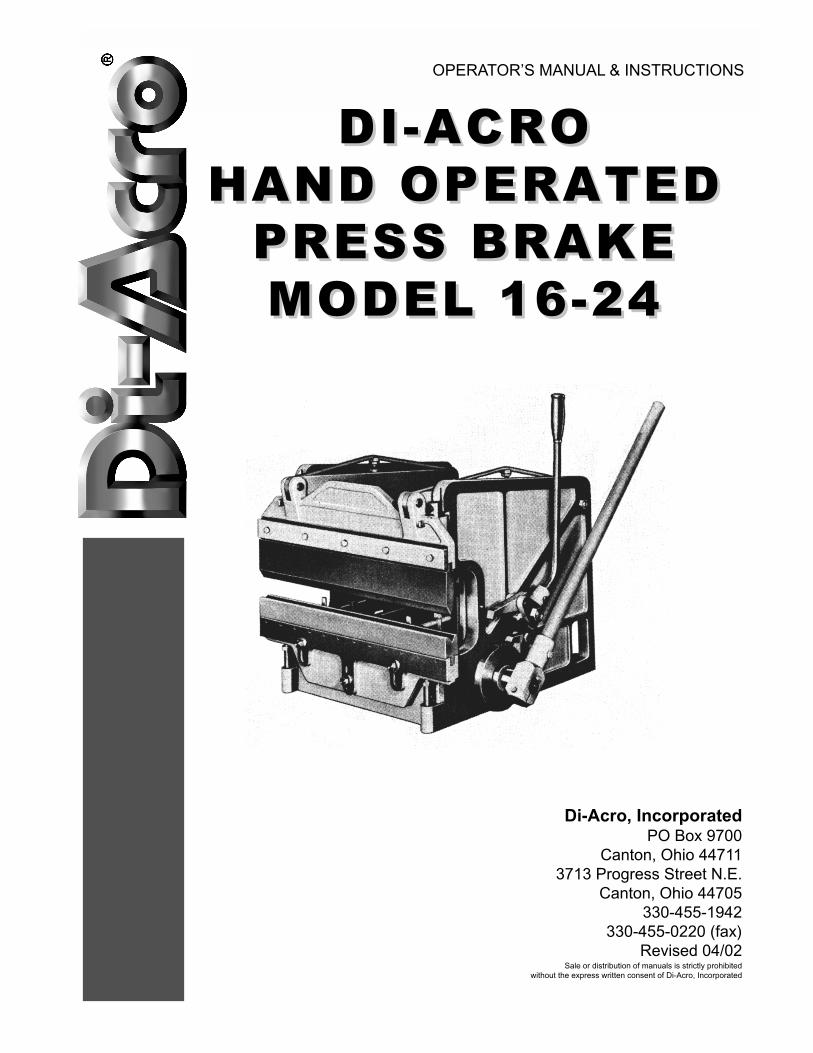
DI-ACRODI-ACRO
HAND OPERATEDHAND OPERATED
PRESS BRAKEPRESS BRAKE
MODEL 16-24MODEL 16-24
Di-Acro, IncorporatedPO Box 9700
Canton, Ohio 44711
3713 Progress Street N.E.
Canton, Ohio 44705
330-455-1942
330-455-0220 (fax)
Revised 04/02
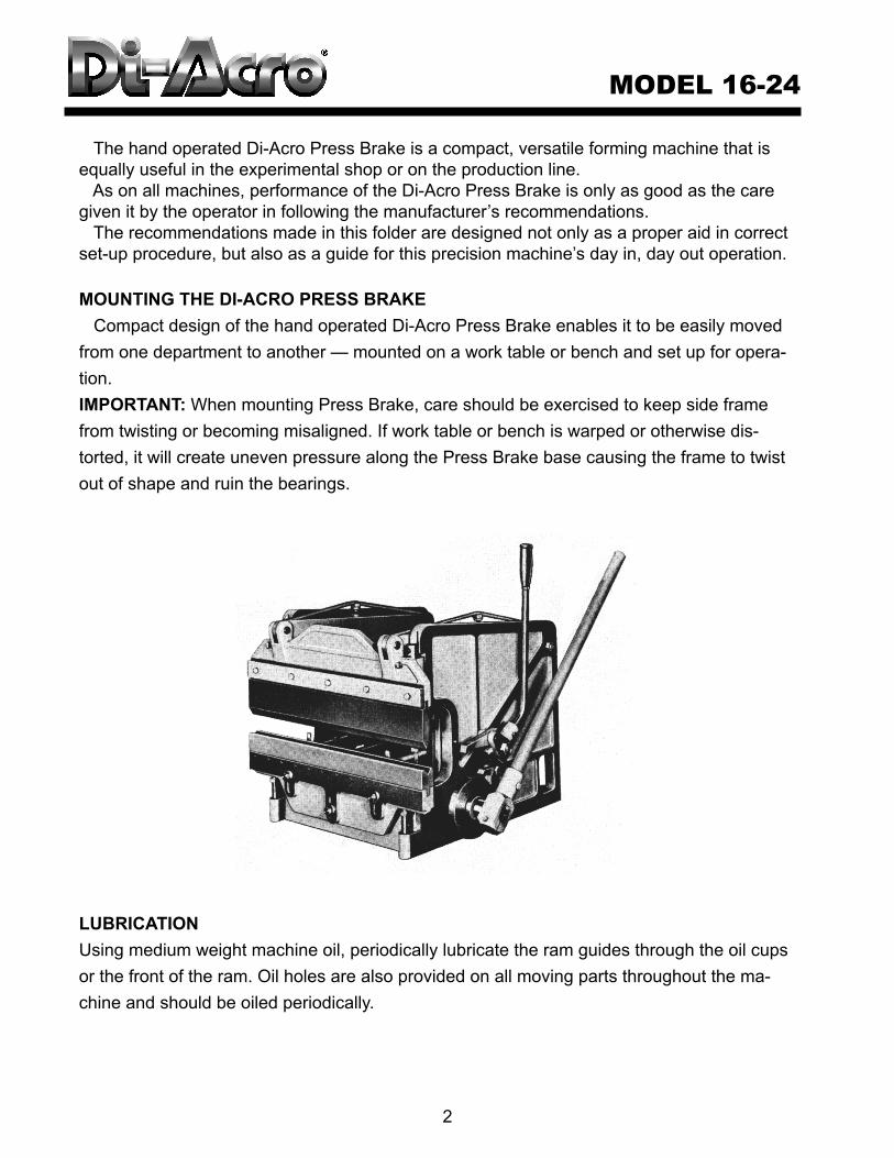
The hand operated Di-Acro Press Brake is a compact, versatile forming machine that is
equally useful in the experimental shop or on the production line.
As on all machines, performance of the Di-Acro Press Brake is only as good as the care
given it by the operator in following the manufacturer’s recommendations.
The recommendations made in this folder are designed not only as a proper aid in correct
set-up procedure, but also as a guide for this precision machine’s day in, day out operation.
MOUNTING THE DI-ACRO PRESS BRAKE
Compact design of the hand operated Di-Acro Press Brake enables it to be easily moved
from one department to another — mounted on a work table or bench and set up for opera-
tion.
IMPORTANT: When mounting Press Brake, care should be exercised to keep side frame
from twisting or becoming misaligned. If work table or bench is warped or otherwise dis-
torted, it will create uneven pressure along the Press Brake base causing the frame to twist
out of shape and ruin the bearings.
LUBRICATION
Using medium weight machine oil, periodically lubricate the ram guides through the oil cups
or the front of the ram. Oil holes are also provided on all moving parts throughout the ma-
chine and should be oiled periodically.
MODEL 16-24
2
ADJUSTING PRESS BRAKE DIES
Lower die on the Di-Acro Press Brake can be adjusted both up and down and in and out to
obtain exact alignment of dies.
TO LINE UP DIES
Lower Operating Handle as far as it will go so upper die is at the bottom of its down
stroke. This is important because maximum forming power cannot be obtained until
Cam Shaft reaches the bottom of its cycle. Also, Ratchet Drive will not automatically
disengage until Operating Handle is at the bottom of its down stroke.
Set proper height of lower die by loosening bolts A and adjusting bed support bolts B.
Center upper and lower dies by adjusting set screws C located along the entire width of
die bed.
1.
2.
3.
ADJUSTING PRESS BRAKE DIES
3
B
A
C

Bending pressures required for other metals as compared to 60,000 PSI tensile mild steel on
chart:Soft Brass
Soft Alluminum
Aluminum Alloys (heat treated)
50% of pressure listed
50% of pressure listed
Same as Steel
Stainless Steel
Chrome Molybdenum
50% more than steel
100% more thatn steel
Pressures underlined are for die with female openings approximately 8 x metal thickness, with radius on male
die equal to metal thickness, and are considered ideal for right angle bending.
TONS PRESSURE REQUIRED TO PUNCH MILD STEEL PLATE
Shearing Strength of 50,000 lbs. per Square Inch
To determine Tons Pressure required to punch a given
number of holes, multiply number of holes by figure
shown in Chart for hole size and Metal Thickness
required.
To reduce Tonnage 50% stagger one Metal Thickness.
PRESSURE IN TONS PER LINEAR FOOT REQUIRED FOR MILD STEEL IN VARIOUS WIDTHS
OF FEMALE DIE OPENINGS (AIR BENDING)
Gauge Inches 1/8""""" 1/4""""" 3/8""""" 1/2""""" 5/8""""" 3/4""""" 7/8"""""
20 0.036 0.35 0.71 1.1 1.4 1.8 2.1 2.5
18 0.048 0.47 0.94 1.4 1.9 2.4 2.8 3.3
16 0.060 0.59 1.2 1.8 2.4 2.9 3.5 4.1
14 0.075 0.74 1.5 2.2 2.9 3.7 4.4 5.2
12 0.105 1.0 2.1 3.1 4.1 5.2 6.2 7.2
11 0.120 1.2 2.4 3.5 4.7 5.9 7.1 8.3
10 0.135 ----- 2.7 4.0 5.3 6.6 8.0 9.3
3/16" 0.187 ----- 3.7 5.5 7.4 9.2 11.1 -----
1/4" 0.250 ----- 4.9 7.4 9.8 12.3 ----- -----
3/8" 0.375 ----- ----- 11.1 ----- ----- ----- -----
Gauge
20
18
16
14
12
11
10
3/16”
1/4”
5/16”
3/8”
7/16”
1/2”
5/8”
3/4”
7/8”
1”
Decimal
.0359
.0478
.0598
.0747
.1046
.1196
.1345
.188
.250
.313
.375
.438
.500
.625
.750
.875
1.000
5/16
2.3
4.0
7.1
11.9
3/8
1.7
3.0
5.6
9.2
1/2
1.1
2.2
3.8
6.3
13.1
19.2
5/8
1.7
2.8
4.7
9.7
14.2
18.6
7/8
1.8
3.0
6.5
9.0
11.9
23.1
1
1.5
2.5
5.6
7.5
9.9
19.3
39.4
1-1/8
2.1
4.6
6.3
8.5
16.4
33.3
1-1/2
3.2
4.4
5.8
11.2
22.7
39.8
61.6
2
2.9
4.0
7.5
15.4
27.0
42.3
61.7
85.2
2-1/2
5.7
11.4
19.7
30.9
45.8
63.6
110.0
3
4.4
9.0
15.3
24.0
35.4
48.8
86.2
138.0
3-1/2
7.4
12.7
19.6
28.6
39.7
70.0
110.0
165.0
4
6.1
10.5
16.3
24.4
33.3
58.3
93.0
137.0
197.0
5
7.7
12.3
17.3
24.6
43.1
68.7
104.0
143.0
6
9.5
14.8
19.4
33.3
53.5
80.7
113.0
7
11.2
15.9
27.4
43.6
64.6
91.2
8
13.1
23.3
36.5
52.9
76.2
Thickness
of MetalDIE OPENING
PRESSURE
4
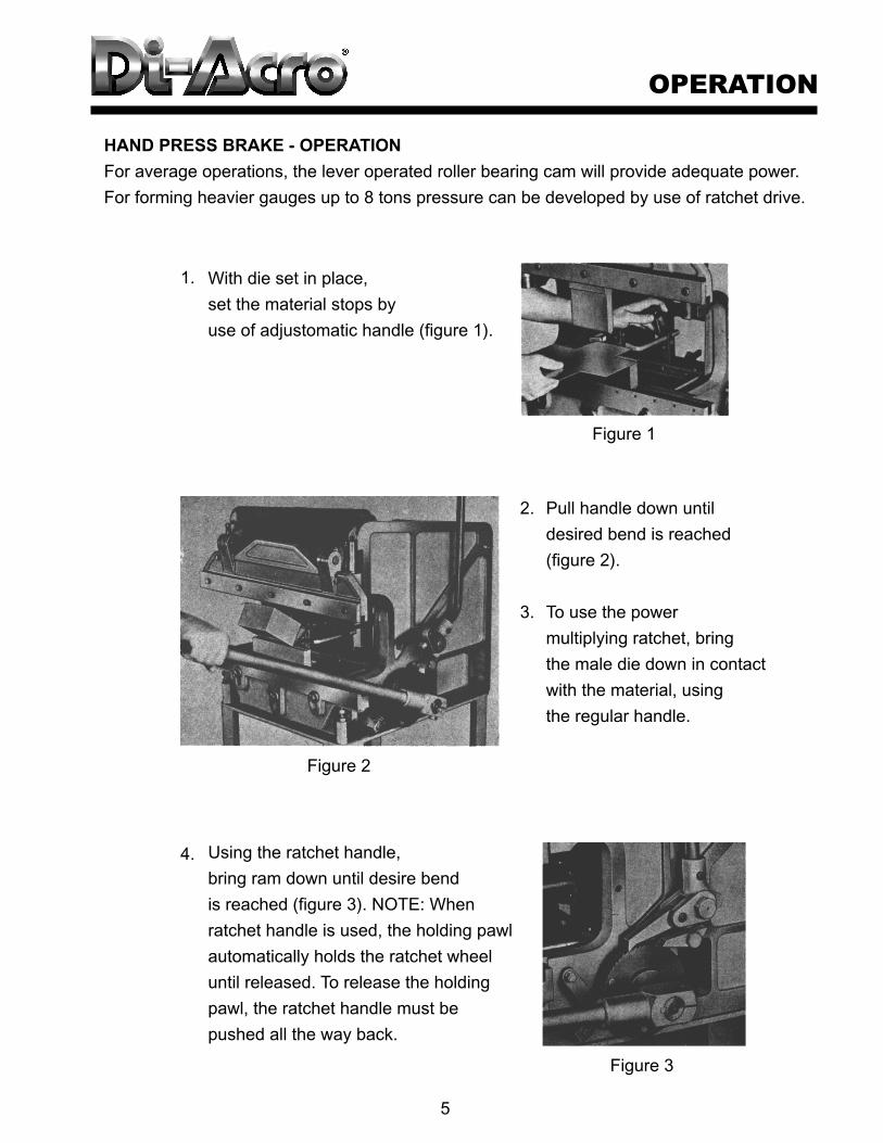
HAND PRESS BRAKE - OPERATION
For average operations, the lever operated roller bearing cam will provide adequate power.
For forming heavier gauges up to 8 tons pressure can be developed by use of ratchet drive.
Pull handle down until
desired bend is reached
(figure 2).
To use the power
multiplying ratchet, bring
the male die down in contact
with the material, using
the regular handle.
Using the ratchet handle,
bring ram down until desire bend
is reached (figure 3). NOTE: When
ratchet handle is used, the holding pawl
automatically holds the ratchet wheel
until released. To release the holding
pawl, the ratchet handle must be
pushed all the way back.
With die set in place,
set the material stops by
use of adjustomatic handle (figure 1).
1.
2.
3.
4.
OPERATION
5
Figure 2
Figure 3
Figure 1
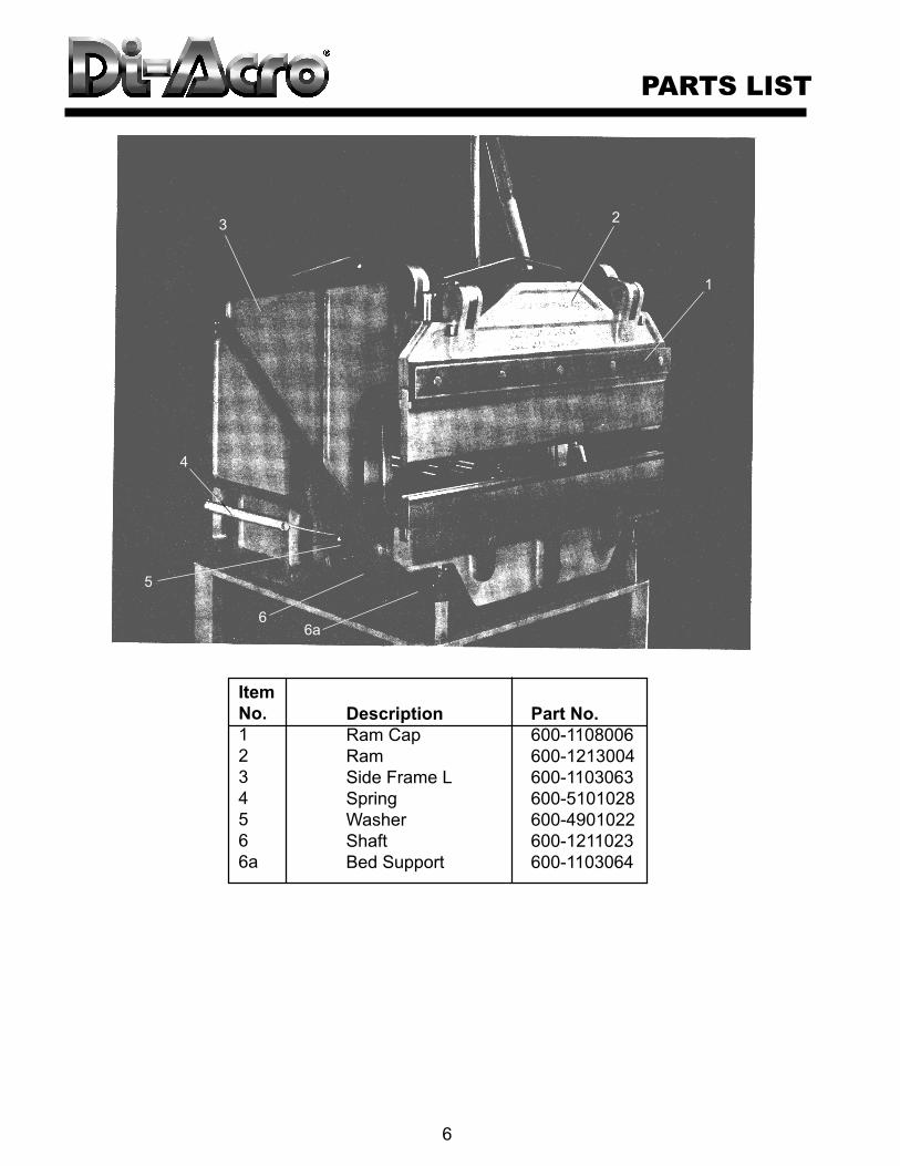
Item
No.
1
2
3
4
5
6
6a
Part No.
600-1108006
600-1213004
600-1103063
600-5101028
600-4901022
600-1211023
600-1103064
Description
Ram Cap
Ram
Side Frame L
Spring
Washer
Shaft
Bed Support
PARTS LIST
6
5
66a
4
32
1

Item
No.
7
8
9
10
11
12
13
14
15
16
17
18
19
20
21
22
23
24
25
26
Description
Spring Container
Washer (3)
Side Frame R
Ram Guide
Yoke (2)
Connecting Link
Handle
Handle Holder
Handle Key
Bed
Bed Support Bolt
Ratchet
Ratchet Handle
Ratchet Handle Holder
Ratchet Bolt
Ratchet Pawl
Check Pawl
Check Pawl Spacer
Ratchet Wheel Stop
Safety Catch
Part No.
600-1218061
4901104
600-1103062
600-1108005
600-1441009
600-1201020
600-1208024
600-1208025
600-5501026
600-1104030
600-4701032
600-1451050
600-1208714
600-1208052
600-4701053
600-1218054
600-1218055
600-1218056
600-1218058
600-1218060
PARTS LIST
7
10 11
9
19
13
20
21
14
15
121817
7
2616
25
23
24
22
Item
No.
27
28
29
30
31
32
33
34
35
36
37
38
39
40
41
42
43
44
45
46
47
Description
Adjustomatic Link (2)
Adjustomatic Trunnion (2)
Adjustomatic Arm (2)
Adjustomatic handle Arm
Adjustomatic Shaft
Yoke Bolt (2)
Power Arm Assy (2)
Power Arm Spacer (2)
Power Arm Bearing (2)
Power Arm Bolt (2)
Material Support Clamp
Material Support Bar
Support Bar Trunnion
Power Arm Washer (2)
Connecting Arm (2)
Ratchet Spring
Check Pawl Bolt
Spacer Bar
Adjustomatic Rod
Gauge Rods
Gauge Clamps
Part No.
315-1441054
600-1451038
600-1451039
600-1451040
600-1451041
600-4701008
600-1215010
600-1215011
600-3770012
600-4701013
500-1441015
600-1441016
600-1441017
600-4901018
600-1212701
600-5101027
600-4701057
600-1108034
600-1441035
600-1415001
600-1451038
PARTS LIST
8
35
3641
3047
27
38
45
43 31
37
39
4442
46
3233 40
34