1594.5/8--en amaline - sal-tec.com36).pdf · nbr (var.: fpm) propeller jl 1040 1.4517 pump casing...
TRANSCRIPT

Nominal speed of propeller [1/min]
501502503
Amaline P 400-500 / 74 UM G
Pump type
Propeller
Nominal propeller diameter [mm]
Nominal propeller diameterwith vane inlet angle
Motor rating
Number of poles of motor
Motor variantUM = Temperature of pumped liquid max. 40 oCYM/XM = flameproof
Material variantG = Pump casing in galvanised steel,
Propeller in JL 1040G1 = Pump casing in 1.4571,
Propeller in JL 1040GC = Pump casing in 1.4571,
Propeller in 1.4517
AmalineType series booklet1594.5/8--EN
Submersible motor recirculation pumpwith ECB propeller
50 Hz
ApplicationsRecirculation of activated sludge from nitrification stages intodenitrification stages of aeration tanks.Economic pumping of storm, river and surface water at lowheads and in land reclamation.Creation of flow in impounded water, e. g. leisure parks.
Pump designWet installed, horizontal propeller pump with submersiblemotor, driven via direct drive (DN 300) or spur gear(DN 500/800). ECB propeller with 3 fixed fibre rejecting blades.Automatic boltfree connection to the discharge pipe.Also available as explosion--proof unit in acc. withATEX II 2 G T3 orT4.
DriveThree-phase asynchronous motor.On explosion--proof pumps in Ex d IIB type of protection,400 V (Var.: 230 V, 500 V, 690 V)
Operating dataHead: H up to 2.0 mCapacity: Q up to 1.5 m3/sMotor power: P2 up to 27 kWTemperature ofpumped liquid: t up to 40 oCNominal diameters: DN 300, 500, 800Operating voltage: U = 400 V, 50 Hz, 3~Enclosure typ: IP 68 to EN 60 529 / IEC 529
Designation
Amaline
2
List of Contents
Page
Product Introduction 1--5
Installation Drawing 6
Technical Data -- Standard Programme / (Standard Variants) 7--8
Design 9--11
Curves 12--19
Dimension Table 20--21
Fastening Equipment, Technical Data, Scope of Supply 22
Order data 23, 24, 28
Amaline
3
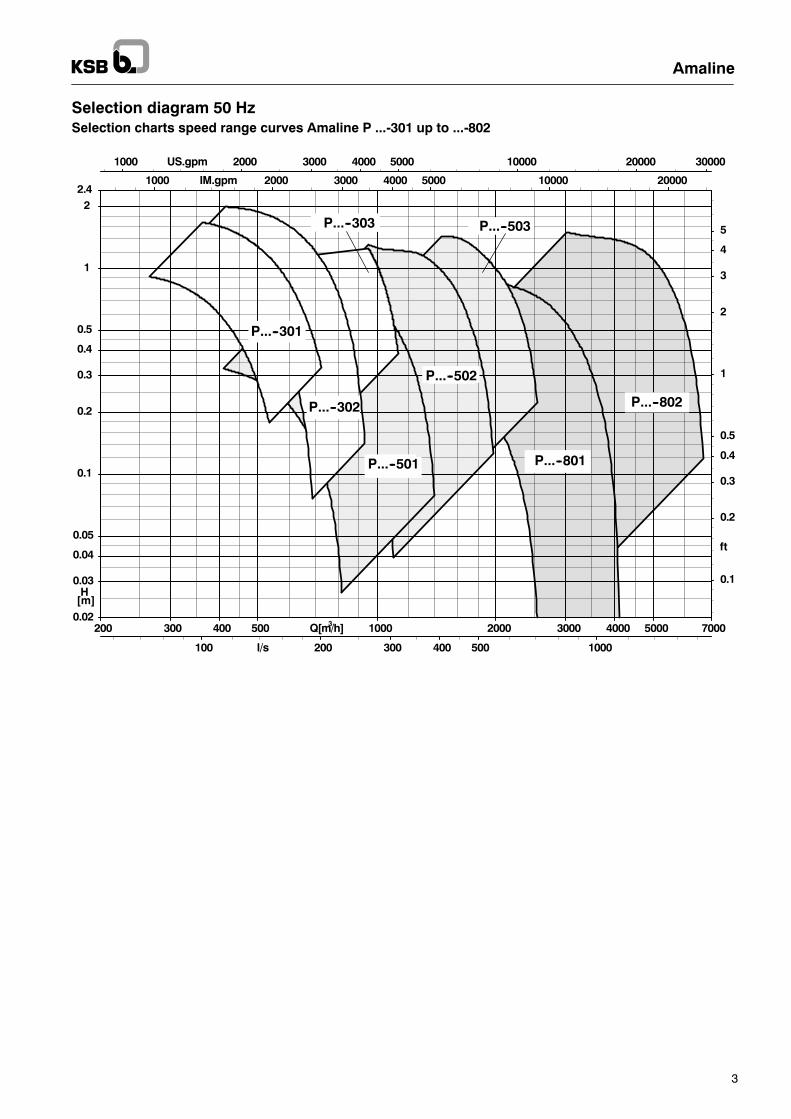
Selection diagram 50 HzSelection charts speed range curves Amaline P ...-301 up to ...-802
1000 2000 3000 4000 5000 10000 20000 30000US.gpm
1000 2000 3000 4000 5000 10000 20000IM.gpm
100 200 300 400 500 1000l/s
200 300 400 500 1000 2000 3000 4000 5000Q[m/h]3
0.1
0.2
0.3
0.4
0.5
1
2
3
4
5
ft
0.02
0.03
0.04
0.05
0.1
0.2
0.3
0.4
0.5
1
22.4
H[m]
P...--301
P...--802
P...--801
P...--503
P...--502
P...--501
P...--303
P...--302
7000
Amaline
4
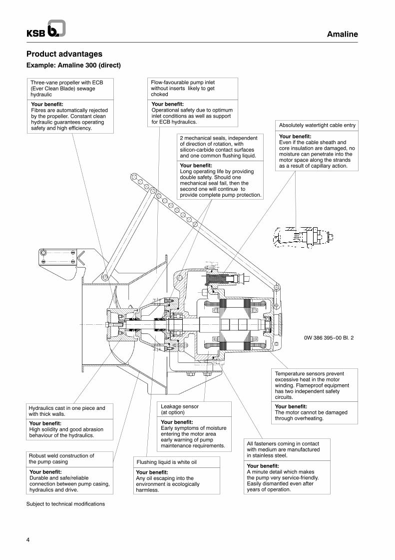
Product advantagesExample: Amaline 300 (direct)
Absolutely watertight cable entry
Your benefit:Even if the cable sheath andcore insulation are damaged, nomoisture can penetrate into themotor space along the strandsas a result of capillary action.
Flushing liquid is white oil
Your benefit:Any oil escaping into theenvironment is ecologicallyharmless.
Your benefit:The motor cannot be damagedthrough overheating.
Temperature sensors preventexcessive heat in the motorwinding. Flameproof equipmenthas two independent safetycircuits.
Flow-favourable pump inletwithout inserts likely to getchoked
Your benefit:Operational safety due to optimuminlet conditions as well as supportfor ECB hydraulics.
Your benefit:Early symptoms of moistureentering the motor areaearly warning of pumpmaintenance requirements.
Leakage sensor(at option)
Hydraulics cast in one piece andwith thick walls.
Your benefit:High solidity and good abrasionbehaviour of the hydraulics.
Robust weld construction ofthe pump casing
All fasteners coming in contactwith medium are manufacturedin stainless steel.
Your benefit:A minute detail which makesthe pump very service-friendly.Easily dismantled even afteryears of operation.
Three-vane propeller with ECB(Ever Clean Blade) sewagehydraulic
Your benefit:Fibres are automatically rejectedby the propeller. Constant cleanhydraulic guarantees operatingsafety and high efficiency.
2 mechanical seals, independentof direction of rotation, withsilicon-carbide contact surfacesand one common flushing liquid.
Your benefit:Long operating life by providingdouble safety. Should onemechanical seal fail, then thesecond one will continue toprovide complete pump protection.
Your benefit:Durable and safe/reliableconnection between pump casing,hydraulics and drive.
0W 386 395--00 Bl. 2
Subject to technical modifications

Amaline
5
Product advantagesExample: Amaline 500/800 (with gear unit)
Absolutely watertight cable entry
Your benefit:Even if the cable sheath andcore insulation are damaged, nomoisture can penetrate into themotor space along the strandsas a result of capillary action.
Three-vane propeller with ECB(Ever Clean Blade) sewagehydraulic
Your benefit:Fibres are automatically rejectedby the propeller. Constant cleanhydraulic guarantees operatingsafety and high efficiency.
Flow-favourable pump inletwithout inserts likely to getchoked
Your benefit:Operational safety due to optimuminlet conditions as well as supportfor ECB hydraulics.
2 mechanical seals, independentof direction of rotation, withsilicon-carbide contact surfacesand one common flushing liquid.
Your benefit:Long operating life by providingdouble safety. Should onemechanical seal fail, then thesecond one will continue toprovide complete pump protection.
Your benefit:Early symptoms of moistureentering the motor areaearly warning of pumpmaintenance requirements.
Leakage sensor(at option)
Your benefit:The motor cannot be damagedthrough overheating.
Temperature sensors preventexcessive heat in the motorwinding. Flameproof equipmenthas two independent safetycircuits.
All fasteners coming in contactwith medium are manufacturedin stainless steel.
Your benefit:A minute detail which makesthe pump very service-friendly.Easily dismantled even afteryears of operation.
Flushing liquid is white oil
Your benefit:Any oil escaping into theenvironment is ecologicallyharmless.
Robust weld construction ofthe pump casing
Hydraulics cast in one piece andwith thick walls.
Your benefit:High solidity and good abrasionbehaviour of the hydraulics.
Your benefit:Durable and safe/reliableconnection between pump casing,hydraulics and drive.
0W 386 062--00 Bl. 2
Subject to technical modifications

Amaline
6
Installation Drawing
0W386473--00
X
B
Dmin.
D1
D2
HÜmin.
h
Y
a2min.
Pos. L1Joining pipe
Pos. L3Lifting clamp
Pos. L2Guide piece
Support(if wall strength is not sufficient, ordistance to the wall is > 500 mm)
Flow direction
Stationary installation of the submersible recirculation pump type Amaline requires a joining pipe of DN 300/500/800, dependingon the pump size.It is set in concrete into the tank wall, where it absorbs all forces (thrust in opposite flow direction and unit weight). The concreteused shall be of sufficient strength (min. B25) in accordance with DIN 1045 or equivalent standards.Responsibility for wall thickness and for accurate positioning of the joining pipe in the wall lies with the system designer and theconstruction company.
The pump unit is guided into the operating position shown by a guide piece consisting of a square rail 100 x 100, which it mountedon the tank wall with 4 heavy--duty anchor bolts or composite anchor bolts.The perfectly vertical attitude of the guide piece, the position relative to the joining pipe and the correct installation of the joiningpipe (with perfectly vertical mating flange parallel to the wall) are of paramount importance for the correct function of the pumpunit.
For dimensions and weights of the pump units please refer to pages 20 ff, also for a detailed illustration of installation parts plusordering information and instructions for selecting available lifting gear.For a detailed description of lifting gear please refer to the type series booklet ”KSB Lifting Equipment”, ref. No. 1596 5.

Amaline
7
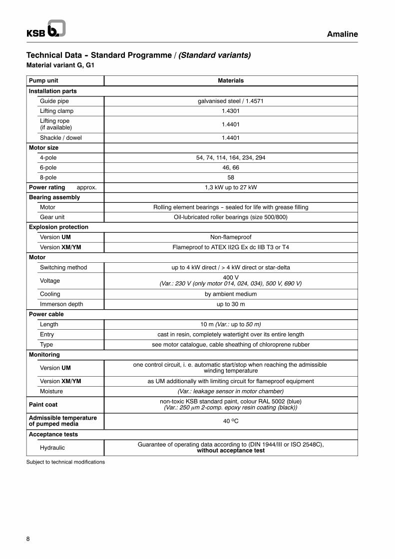
Technical Data -- Standard Programme / (Standard variants)Material variant G, G1
EN DIN ASTM equivalent
JL 1040 GG-25 A 48 Class 40 B
1.4517 1.4517 A 743 CD 4 MCU
1.4021 1.4021 A 276 Type 420
1.4301 1.4301 A 276 Type 316
1.4122 1.4122 Sim. A 276 Type 440
1.4571 1.4571 A 276 Type 316 Ti
C 45 + N C 45 N A 576 Gr. 1045
NBR NBR NBR
FPM FPM FKM
G = standard version-- main components in cast iron (JL 1040)-- pump casing in galvanised steel
G1 = like G -- but:-- pump casing in 1.4571
GC = like G1 -- but:-- propeller in 1.4517
Variants
...-300 ./ ... G 1)
...-500 ./ ... G 2)
...-800 ./ ... G 2)
...-300 ./ ... G1 1)
...-500 ./ ... G1 2)
...-800 ./ ... G1 2)
...-300 ./ ... GC 1)
...-500 ./ ... GC 2)
...-800 ./ ... GC 2)
Component Materials
Pump unit
Motor casing JL 1040
Bearing bracket JL 1040
Gear unit JL 1040 (only for size 500/800)
Seat ring holder JL 1040
Impeller drive shaftAmaline 300: 1.4021
Amaline 500/800: 1.4122
Motor shaftAmaline 300: 1.4021
Amaline 500/800: C45 + N
Mechanical seals
-- propellers sideBellows-type mechanical seal SiC/SiC-FPM
(Var.: mechanical seal with covered spring SiC/SiC-FPM)
-- gear unit side ormotor side Bellows-type mechanical seal SiC/SiC-FPM
O-RingNBR
(Var.: FPM)
Propeller JL 1040 1.4517
Pump casing galvanised steel 1.4571
Bolts and nuts A4 (equivalent to 1.4571)
1) direct-drive version2) with gear unit
Amaline
8
Technical Data -- Standard Programme / (Standard variants)Material variant G, G1
Pump unit Materials
Installation parts
Guide pipe galvanised steel / 1.4571
Lifting clamp 1.4301
Lifting rope(if available) 1.4401
Shackle / dowel 1.4401
Motor size
4-pole 54, 74, 114, 164, 234, 294
6-pole 46, 66
8-pole 58
Power rating approx. 1,3 kW up to 27 kW
Bearing assembly
Motor Rolling element bearings -- sealed for life with grease filling
Gear unit Oil-lubricated roller bearings (size 500/800)
Explosion protection
Version UM Non-flameproof
Version XM/YM Flameproof to ATEX II2G Ex dc IIB T3 or T4
Motor
Switching method up to 4 kW direct / > 4 kW direct or star-delta
Voltage 400 V(Var.: 230 V (only motor 014, 024, 034), 500 V, 690 V)
Cooling by ambient medium
Immerson depth up to 30 m
Power cable
Length 10 m (Var.: up to 50 m)
Entry cast in resin, completely watertight over its entire length
Type see motor catalogue, cable sheathing of chloroprene rubber
Monitoring
Version UM one control circuit, i. e. automatic start/stop when reaching the admissiblewinding temperature
Version XM/YM as UM additionally with limiting circuit for flameproof equipment
Moisture (Var.: leakage sensor in motor chamber)
Paint coat non-toxic KSB standard paint, colour RAL 5002 (blue)(Var.: 250 mm 2-comp. epoxy resin coating (black))
Admissible temperatureof pumped media 40 oC
Acceptance tests
Hydraulic Guarantee of operating data according to (DIN 1944/III or ISO 2548C),without acceptance test
Subject to technical modifications

1
2
3
Amaline
9
Design
HÜ = covering
Hgeo = geodetic discharge head
HVtot. = plant losses
HVR = pipework losses
HVK = valve losses
HVA = outlet losses
0W386472--00
HÜmin.
Hgeo
HVK / HVKHVR
Flow direction
h
Example:Given:
Flow rate: Q = 1350 m3/h
Geodetic discharge head:Hgeo = 0.3 m
Preliminary selection Amaline with DN 500 (see fig. 1)
Determination of outlet losses (see fig. 2)
HVA = v2/2g = 0.15 m
Determination of discharge head
H = Hgeo + HVtot.
HVtot. = HVR + HVK + HVA
HVR = 0 m (short pipeline)
HVK = 0.15 m (data by manufacturer. consider HVK (Q) course)
HVA = v2/2g = 0.15 m
→ H = 0.3 m + 0 m + 0.15 m + 0.15 m = 0.6 m

4
Amaline
10
Preliminary pump selection (see fig. 1)
→ P 400-50...
1000 2000 3000 4000 5000 10000 20000 30000US.gpm1000 2000 3000 4000 5000 10000 20000IM.gpm
100 200 300 400 500 1000l/s
200 300 400 500 1000 2000 3000 4000 5000Q[m/h]3
0.1
0.2
0.3
0.40.5
1
2
3
45
ft
0.02
0.03
0.040.05
0.1
0.2
0.3
0.40.5
1
22.4
H[m]
--301
--802
--803
--503
--502
--501
--303
--302
7000
D
Fig. 1: Preliminary selection hydraulic diameter
D
HVA[m]
Q [l/s]
Fig. 2: Outlet loss HVA = v2/2g

5
6
Hreq.
Amaline
11
Duty point = design point (acc. to fig. 3)
The design point can be reached without deviation by using a frequency converter.
2000 4000 6000 80001000 US.gpm
2000 4000 60001000 7000IM.gpm
100 200 300 400 50060 540l/s
200 400 600 800 1000 1400 1600 1800 2000m/h3
200 400 600 800 1000 1400 1600 1800 2000m/h3
Förderstrom/Flow/Débit/Portata/Capaciteit/Caudal
0
2
4
ft
0.0
0.5
1.0
1.4
mFörderhöheTDHHauteurPrevalenzaOpvoerhoogteAltura
0
10
hp
0
5
10
12
kWLeistungsbedarfPower InputPuiss. abs.Potenza ass.OpgenomenvermogenPotencia nec.
η[%]
n=260
61.9
50
50
54
54
58
58
60
60
n=260
n=395
62.5
50
50
54
54
58
58
60
60
62
62
n=395
n=465
62.8
50
50
54
54
58
58
60
60
62
62
n=465
Qmin
Q= 1350 m3/hH= 0.6 m
plant curve
Fig. 3: Selection charts speed Amaline P ...-502
Operational speed is 395 1/min or 465 1/min. All pump units have a sufficient motor power reserve(motor power utilization: max. 85 %).
Designation Speed Motor power Drive with gear unit Transmission ratio
neff. P2Amaline P ... [min--1] [kW]
400-502 / 54 YMG 395 4.0 S34B 3.62
400-502 / 54 UMG / XMG 395 5.5 S34B 3.62
400-502 / 74 UMG / XMG 398 7.5 S34B 3.62
460-502 / 114 UMG 465 11.8 S44B 3.15
Operation characteristics
Pipework length: L > 5 x D:When starting the pump, larger discharge heads are to be stated due to accelarationof the pipework contents. That is why the pump briefly exceeds its operating limits!
Operating in lifting pipes:The duty point for filling the pipe has to be inferior to the operating limit:Hmax. ≤ operating limit
Discharge heads and capacity data apply to media with a density of ρ = 1 kg/dm3 anda kinematic viscosity ν to 20 mm2/s.
Amaline
12
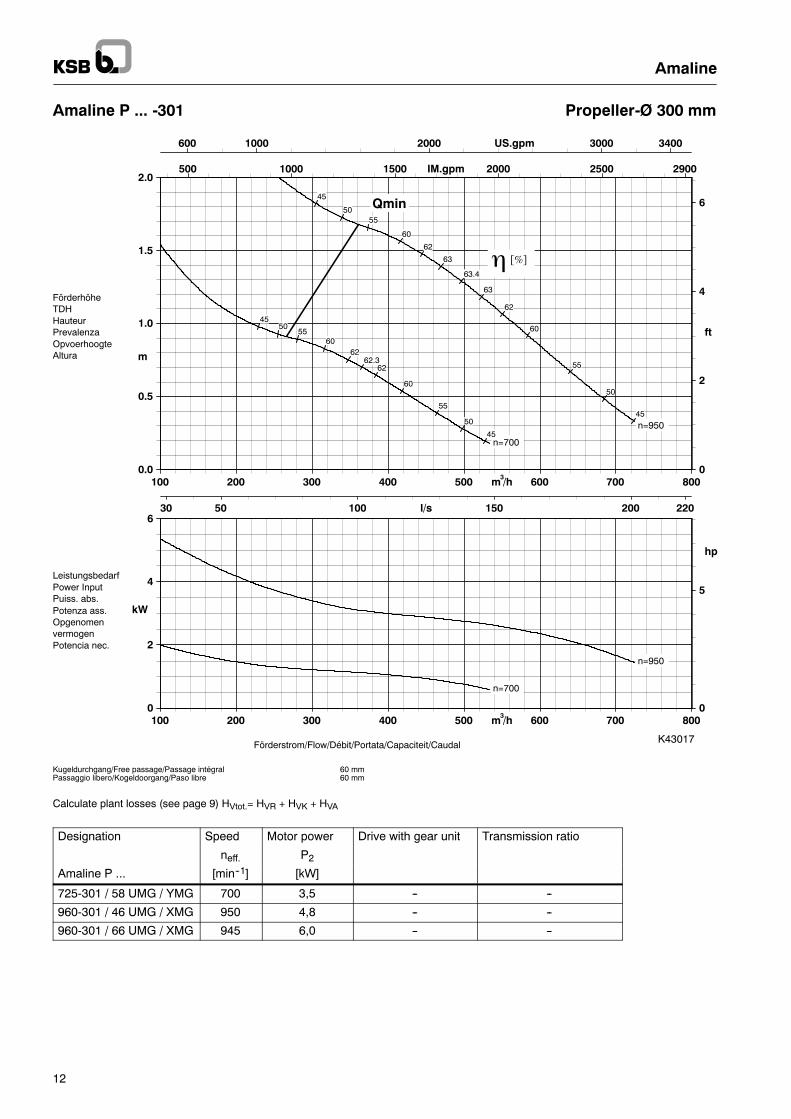
Amaline P ... -301 Propeller-Ø 300 mm
Kugeldurchgang/Free passage/Passage intégralPassaggio libero/Kogeldoorgang/Paso libre
60 mm60 mm
1000 2000 3000600 3400US.gpm
500 1000 1500 2000 2500 2900IM.gpm
50 100 150 20030 220l/s
100 200 300 400 500 600 700 800m /h3
100 200 300 400 500 600 700 800m /h3
Förderstrom/Flow/Débit/Portata/Capaciteit/Caudal
0
2
4
6
ft
0.0
0.5
1.0
1.5
2.0
m
FörderhöheTDHHauteurPrevalenzaOpvoerhoogteAltura
0
5
hp
0
2
4
6
kW
LeistungsbedarfPower InputPuiss. abs.Potenza ass.OpgenomenvermogenPotencia nec.
η [%]
n=700
62.3
45
45
50
50
55
55
60
60
62
62
n=700
n=950
63.4
45
45
50
50
55
55
60
60
62
62
63
63
n=950
Qmin
K43017
Calculate plant losses (see page 9) HVtot.= HVR + HVK + HVA
Designation Speed Motor power Drive with gear unit Transmission ratio
neff. P2Amaline P ... [min--1] [kW]
725-301 / 58 UMG / YMG 700 3,5 -- --
960-301 / 46 UMG / XMG 950 4,8 -- --
960-301 / 66 UMG / XMG 945 6,0 -- --

Amaline
13
Amaline P ... -302 Propeller-Ø 300 mm
Kugeldurchgang/Free passage/Passage intégralPassaggio libero/Kogeldoorgang/Paso libre
60 mm60 mm
1000 2000 3000 4000600 4400US.gpm
1000 2000 3000400 3600IM.gpm
50 100 150 200 25030 270l/s
200 400 600 800 1000100 m /h3
200 400 600 800 1000100 m /h3
Förderstrom/Flow/Débit/Portata/Capaciteit/Caudal
0
2
4
6
ft
0.0
0.5
1.0
1.5
2.0
2.4
m
FörderhöheTDHHauteurPrevalenzaOpvoerhoogteAltura
0
10
hp
0
5
10
kWLeistungsbedarfPower InputPuiss. abs.Potenza ass.OpgenomenvermogenPotencia nec.
η [%]
n=700
61
45
45
50
50
55
55
60
60
n=700
n=950
62
45
45
50
50
55
55
60
60
n=950
Qmin
K43018
Calculate plant losses (see page 9) HVtot.= HVR + HVK + HVA
Designation Speed Motor power Drive with gear unit Transmission ratio
neff. P2Amaline P ... [min--1] [kW]
725-302 / 58 UMG / YMG 700 3,5 -- --
960-302 / 46 UMG / XMG 950 4,8 -- --
960-302 / 66 UMG / XMG 945 6,0 -- --
Amaline
14
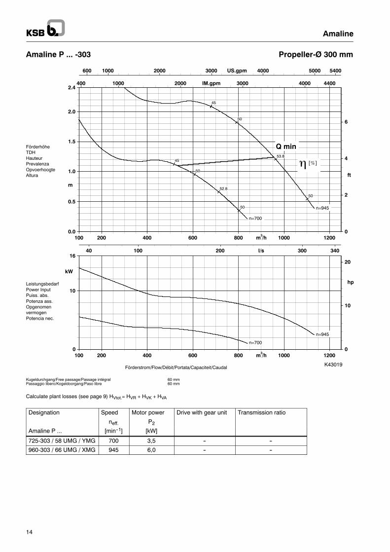
Amaline P ... -303 Propeller-Ø 300 mm
Kugeldurchgang/Free passage/Passage intégralPassaggio libero/Kogeldoorgang/Paso libre
60 mm60 mm
1000 2000 3000 4000 5000600 5400US.gpm
1000 2000 3000 4000400 4400IM.gpm
100 200 30040 340l/s
200 400 600 800 1000 1200100 m /h3
200 400 600 800 1000 1200100 m /h3
Förderstrom/Flow/Débit/Portata/Capaciteit/Caudal
0
2
4
6
ft
0.0
0.5
1.0
1.5
2.0
2.4
m
FörderhöheTDHHauteurPrevalenzaOpvoerhoogteAltura
0
10
20
hp
0
10
16
kW
LeistungsbedarfPower InputPuiss. abs.Potenza ass.OpgenomenvermogenPotencia nec.
η [%]
n=700
52.8
45
50
50
n=700
n=945
53.8
4545
50
50
n=945
Q min
K43019
Calculate plant losses (see page 9) HVtot.= HVR + HVK + HVA
Designation Speed Motor power Drive with gear unit Transmission ratio
neff. P2Amaline P ... [min--1] [kW]
725-303 / 58 UMG / YMG 700 3,5 -- --
960-303 / 66 UMG / XMG 945 6,0 -- --

Amaline
15
Amaline P ... -501 Propeller-Ø 480 mm
1000 2000 3000 4000 5000 6000US.gpm
1000 2000 3000 4000 5000IM.gpm
100 200 300 400l/s
200 400 600 800 1000 1200 1400m#/h
200 400 600 800 1000 1200 1400m#/h0
2
4
ft
0.0
0.5
1.0
1.4
m
0
5
10
hp
0
2
4
6
8
kW
η [%]
Qmin
n=260
61.2
50
50
56
56
60
60
n=260
n=392
61.7
50
50
56
56
60
60
n=392
n=446
62
50
50
56
56
60
60
n=446
Kugeldurchgang/Free passage/Passage intégralPassaggio libero/Kogeldoorgang/Paso libre
100 mm100 mm
Förderstrom/Flow/Débit/Portata/Capaciteit/Caudal
FörderhöheTDHHauteurPrevalenzaOpvoerhoogteAltura
LeistungsbedarfPower InputPuiss. abs.Potenza ass.OpgenomenvermogenPotencia nec.
K43020
Calculate plant losses (see page 9) HVtot.= HVR + HVK + HVA
Designation Speed Motor power Drive with gear unit Transmission ratio
neff. P2Amaline P ... [min--1] [kW]
400-501 / 54 YMG 395 4,0 S34B 3,62
460-501 / 74 UMG / XMG 446 7,5 S34B 3,232

Amaline
16
Amaline P ... -502 Propeller-Ø 480 mm
FörderhöheTDHHauteurPrevalenzaOpvoerhoogteAltura
LeistungsbedarfPower InputPuiss. abs.Potenza ass.OpgenomenvermogenPotencia nec.
Kugeldurchgang/Free passage/Passage intégralPassaggio libero/Kogeldoorgang/Paso libre
100 mm100 mm
Förderstrom/Flow/Débit/Portata/Capaciteit/CaudalK43021
2000 4000 6000 8000US.gpm
2000 4000 6000IM.gpm
100 200 300 400 500l/s
200 400 600 800 1000 1200 1400 1600 1800 2000m#/h
200 400 600 800 1000 1200 1400 1600 1800 2000m#/h0
2
4
ft
0.0
0.5
1.0
1.5
m
0
10
20
hp
0
5
10
15
kW
η [%]
Qmin
n=260
63.8
50
50
56
56
60
60
63
63
n=260
n=395
64.4
50
50
56
56
60
60
63
63
n=395
n=465
64.7
50
50
56
56
60
60
63
63
n=465
Calculate plant losses (see page 9) HVtot.= HVR + HVK + HVA
Designation Speed Motor power Drive with gear unit Transmission ratio
neff. P2Amaline P ... [min--1] [kW]
400-502 / 54 YMG 395 4,0 S34B 3,62
400-502 / 54 UMG / XMG 395 5,5 S34B 3,62
400-502 / 74 UMG / XMG 398 7,5 S34B 3,62
460-502 / 114 UMG 465 11,8 S44B 3,15

Amaline
17
Amaline P ... -503 Propeller-Ø 480 mm
Kugeldurchgang/Free passage/Passage intégralPassaggio libero/Kogeldoorgang/Paso libre
100 mm100 mm
Förderstrom/Flow/Débit/Portata/Capaciteit/Caudal
FörderhöheTDHHauteurPrevalenzaOpvoerhoogteAltura
LeistungsbedarfPower InputPuiss. abs.Potenza ass.OpgenomenvermogenPotencia nec.
K43022
2000 4000 6000 8000 10000US.gpm
2000 4000 6000 8000IM.gpm
200 400 600l/s
500 1000 1500 2000 2500m#/h
500 1000 1500 2000 2500m#/h0
2
4
ft
0.0
0.5
1.0
1.5
m
0
10
20
hp
0
10
20
kW
η [%]
Qmin
n=260
57.3
50
50
56
56
n=260
n=395
57.8
50
50
56
56
57.5
57.5
n=395
n=465
58.1
50
50
56
56
57.5
57.5
n=465
Calculate plant losses (see page 9) HVtot.= HVR + HVK + HVA
Designation Speed Motor power Drive with gear unit Transmission ratio
neff. P2Amaline P ... [min--1] [kW]
260-503 / 54 YMG 261 4,0 S34B 5,47
400-503 / 54 UMG / XMG 395 5,5 S34B 3,62
400-503 / 74 UMG / XMG 398 7,5 S34B 3,62
460-503 / 164 UMG 465 16 S44B 3,15
Amaline
18
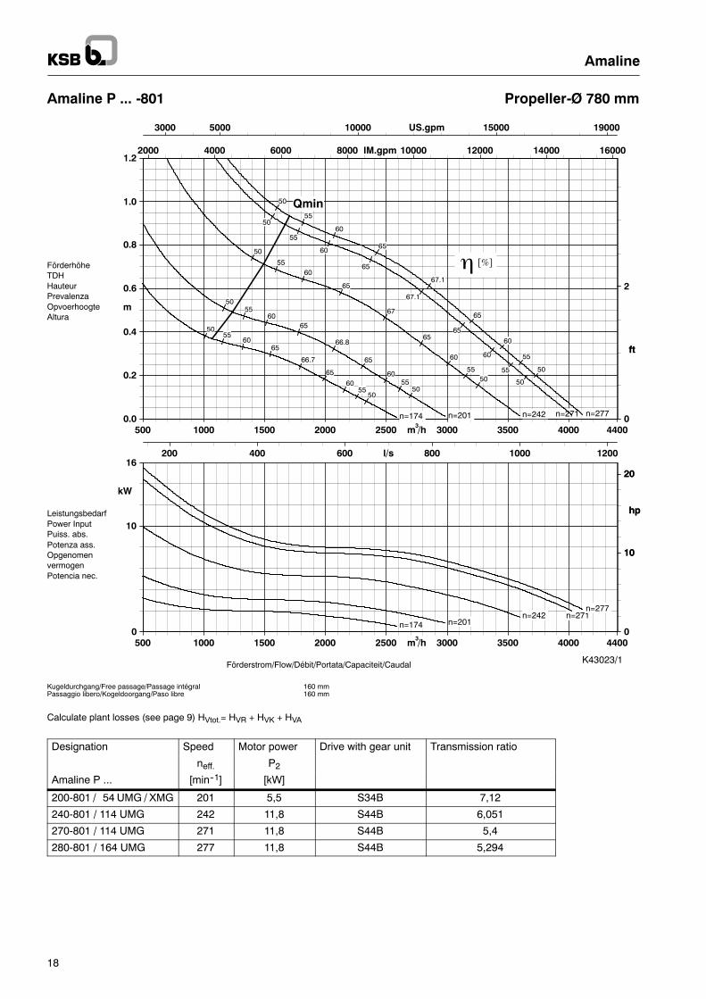
Amaline P ... -801 Propeller-Ø 780 mm
5000 10000 150003000 19000US.gpm
2000 4000 6000 8000 10000 12000 14000 16000IM.gpm
200 400 600 800 1000 1200l/s
500 1000 1500 2000 2500 3000 3500 4000 4400m /h3
500 1000 1500 2000 2500 3000 3500 4000 4400m /h30
2
ft
0.0
0.2
0.4
0.6
0.8
1.0
1.2
m
0
10
20
hp
0
10
16
kW
n=174
66.7
50
50
55
55
60
60
65
65
n=174
n=201
66.8
50
50
55
55
60
60
65
65
n=201
n=242
67
50
50
55
55
60
60
65
65
n=242
n=271
67.1
50
50
55
55
60
60
65
65
n=271
n=277
67.1
50
50
55
55
60
60
65
65
n=277
Qmin
Kugeldurchgang/Free passage/Passage intégralPassaggio libero/Kogeldoorgang/Paso libre
160 mm160 mm
Förderstrom/Flow/Débit/Portata/Capaciteit/Caudal
ft
FörderhöheTDHHauteurPrevalenzaOpvoerhoogteAltura
10
20
hpLeistungsbedarfPower InputPuiss. abs.Potenza ass.OpgenomenvermogenPotencia nec.
K43023/1
η [%]
Calculate plant losses (see page 9) HVtot.= HVR + HVK + HVA
Designation Speed Motor power Drive with gear unit Transmission ratio
neff. P2Amaline P ... [min--1] [kW]
200-801 / 54 UMG / XMG 201 5,5 S34B 7,12
240-801 / 114 UMG 242 11,8 S44B 6,051
270-801 / 114 UMG 271 11,8 S44B 5,4
280-801 / 164 UMG 277 11,8 S44B 5,294
Amaline
19
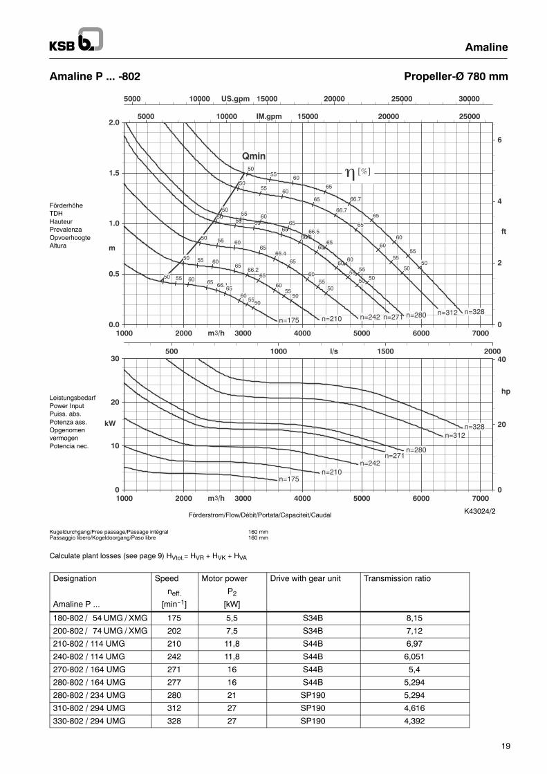
Amaline P ... -802 Propeller-Ø 780 mm
5000 10000 15000 20000 25000 30000US.gpm
5000 10000 15000 20000 25000IM.gpm
500 1000 1500 2000l/s
1000 2000 3000 4000 5000 6000 7000m#/h
1000 2000 3000 4000 5000 6000 7000m#/h0
2
4
6
ft
0.0
0.5
1.0
1.5
2.0
m
0
20
40
hp
0
10
20
30
kW
Qmin
n=175
66.1
50
50
55
55
60
60
6565
n=175
n=210
66.2
50
50
55
55
60
60
65
65
n=210
n=242
66.4
50
50
55
55
60
60
65
65
n=242
n=271
66.5
50
50
55
55
60
60
65
65
n=271
n=280
66.5
50
50
55
55
60
60
65
65
n=280
n=312
66.7
50
50
55
55
60
60
65
65
n=312
n=328
66.7
50
50
55
55
60
60
65
65
n=328
Kugeldurchgang/Free passage/Passage intégralPassaggio libero/Kogeldoorgang/Paso libre
160 mm160 mm
Förderstrom/Flow/Débit/Portata/Capaciteit/Caudal
FörderhöheTDHHauteurPrevalenzaOpvoerhoogteAltura
LeistungsbedarfPower InputPuiss. abs.Potenza ass.OpgenomenvermogenPotencia nec.
K43024/2
η [%]
Calculate plant losses (see page 9) HVtot.= HVR + HVK + HVA
Designation Speed Motor power Drive with gear unit Transmission ratio
neff. P2Amaline P ... [min--1] [kW]
180-802 / 54 UMG / XMG 175 5,5 S34B 8,15
200-802 / 74 UMG / XMG 202 7,5 S34B 7,12
210-802 / 114 UMG 210 11,8 S44B 6,97
240-802 / 114 UMG 242 11,8 S44B 6,051
270-802 / 164 UMG 271 16 S44B 5,4
280-802 / 164 UMG 277 16 S44B 5,294
280-802 / 234 UMG 280 21 SP190 5,294
310-802 / 294 UMG 312 27 SP190 4,616
330-802 / 294 UMG 328 27 SP190 4,392
Amaline
20
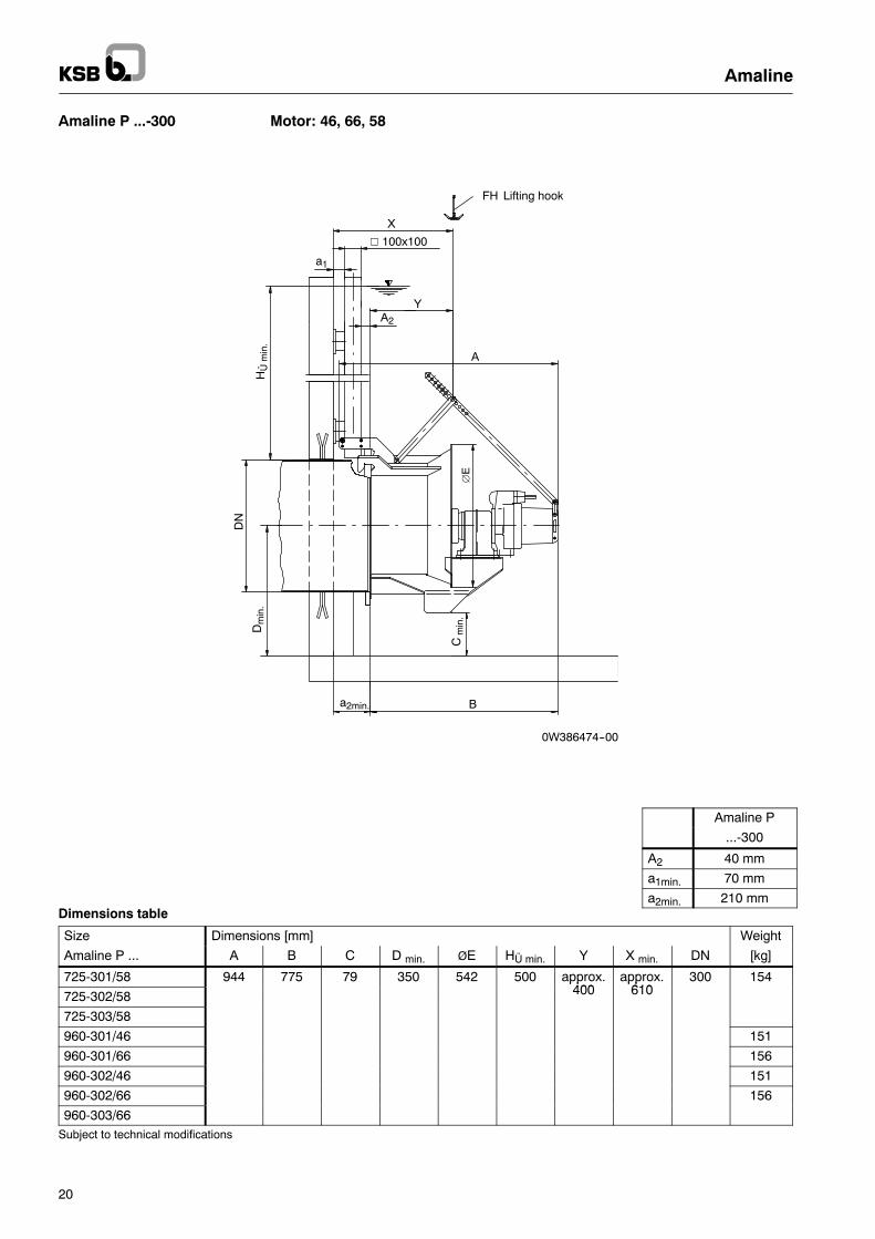
Amaline P ...-300 Motor: 46, 66, 58
V 100x100
0W386474--00
DN
A
Dmin.
B
HÜmin.
Cmin.
a2min.
∅E
A2
a1
X
Y
FH Lifting hook
Amaline P
...-300
A2 40 mm
a1min. 70 mm
a2min. 210 mmDimensions table
Size Dimensions [mm] Weight
Amaline P ... A B C D min. ØE HÜ min. Y X min. DN [kg]
725-301/58 944 775 79 350 542 500 approx.400
approx.610
300 154
725-302/58
pp400
pp610
725-303/58
960-301/46 151
960-301/66 156
960-302/46 151
960-302/66 156
960-303/66Subject to technical modifications

V 100x100
0W386474--00
DN
A
Dmin.
B
HÜmin.
Cmin.
a2min.
∅E
A2
a1
X
Y
FH Lifting hook
Amaline
21
Amaline P ...-500/800 Motor: 54, 74, 114, 164, 234, 294
Amaline P
...-500 ...-800
A2 50 mm 55 mm
a1min. 70 mm 70 mm
a2min. 220 mm 225 mmDimensions table
Size Dimensions [mm] Weight
Amaline P ... A B C D min. ØE HÜ min. Y X min. DN [kg]
260-503/54 1175 992 85 450 730 700 approx.400
approx.620
500 229
400-501/54
pp400
pp620 229
400-502/54 229
400-502/74 236
400-503/54 229
400-503/74 236
460-501/74 236
460-502/114 1231 1048 approx.470
approx.690
283
460-503/164
pp470
pp690 306
180-802/54 1350 1162 600 1030 1100 approx.500
approx.725
800 334
200-801/54
pp500
pp725 334
200-802/74 341
210-802/114 1406 1218 approx.550
approx.775
388
240-801/114 1536 1348 approx.620
approx.845
438
240-802/114
pp620
pp845 438
270-801/114 438
270-802/164 approx.670
approx.895
461
280-801/114
pp670
pp895 461
280-802/164 461
280-802/234 1619 1431 approx.640
approx.865
560
310-802/294 1595 1407
pp640
pp865 580
330-802/294Subject to technical modifications
Amaline
22
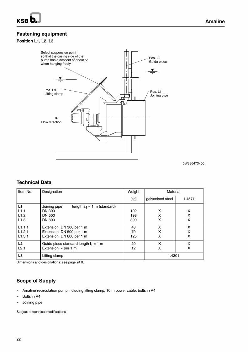
Fastening equipmentPosition L1, L2, L3
0W386473--00
Pos. L1Joining pipe
Pos. L3Lifting clamp
Pos. L2Guide piece
Flow direction
Select suspension pointso that the casing side of thepump has a descent of about 5°when hanging freely.
Technical Data
Item No. Designation Weight Material
[kg] galvanised steel 1.4571
L1L1.1L1.2L1.3
Joining pipe length a3 = 1 m (standard)DN 300DN 500DN 800
102198390
XXX
XXX
L1.1.1L1.2.1L1.3.1
Extension DN 300 per 1 mExtension DN 500 per 1 mExtension DN 800 per 1 m
4879125
XXX
XXX
L2L2.1
Guide piece standard length l1 = 1 mExtension -- per 1 m
2012
XX
XX
L3 Lifting clamp 1.4301
Dimensions and designations: see page 24 ff.
Scope of Supply
-- Amaline recirculation pump including lifting clamp, 10 m power cable, bolts in A4
-- Bolts in A4
-- Joining pipe
Subject to technical modifications

Amaline
23
Order dataAssembly acessories -- standard
S
X
l 3
l 2
l 1DN
D1
h
D2
Y
a1
a3
10
a4
a2
100
A2 100
Y
approx.
10
1. Guide piece
2. Joining pipe
min.120
Y
X
a1
120
a 5
180
a1
60150
100x100
100x100
100x100
∅13
α
Size Dimension [mm] Remark
a1 min. 70 mm
a2 a2 = a1 + A2 + 100 mmDN 300: A2 = 40 mmDN 500: A2 = 50 mmDN 800: A2 = 55 mm
a3 depends on plant
a4 if necessary
a5 >0.5 x ØE,(see page 20, 21, 22)only with angled version
l1 acc. to installation depth
l2 acc. to installation depthmin. 120 mm
l3 acc. to installation depth
α Note:a1 min.= 70 + 50 x tan α
Dimensions DN, D1, D2, S and h see table p. 25
Subject to technical modifications

Amaline
24
Dimensions table
Size DN Gear unit D1 D2 S h
Amaline [mm] [mm]
P ...-300(-301, -302, -303) 300 -- 440 324 20 60
P ...-500(-501, -502, -503) 500 x 645 508 30 70
P ...-800(-801, -802) 800 x 975 813 30 80
Subject to technical modifications
The following data is required for ordering the guide piece:-- l1, l2, l3, and a1, (ggf. auch a5 or α)
-- Material (galvanised steel / 1.4571)
The following data is required for ordering the joining pipe:-- a3, a4-- Material (galvanised steel / 1.4571)
Material variants galvanised steel 1.4571
Designation Size Ident. No.
1. Guide piece 300/500/800 19 219 569 19 219 568
Do not forget the following ordering data:
l1 = mm
l2 = mm
l3 = mm
a1 = mm
a5 = mm
α =o
Fasteners for item 1 (guide piece):
Composite anchor bolts M12x160 (threaded pin and mortar cartridge):Ident. No.: 01 093 519 + 01 093 565 (A4), 4 pcs required
2. Fit joining pipe 300 19 219 500 19 219 571
500 19 219 572 19 219 573
800 19 219 574 19 219 575
Do not forget the following ordering data:
a3 = mm
a4 = mm

Amaline
25

Amaline
26

Amaline
27
KSB AktiengesellschaftP.O. Box 200743 • 06008 Halle (Saale) • Turmstraße 92 • 06110 Halle (Germany)Tel. +49 (345) 48 26 0 • Fax +49 (345) 48 26 46 99 • www.ksb.com
1594.5/8--EN
12/2011
Subjecttotechnicalm
odificationwithoutpriornotice.
Amaline
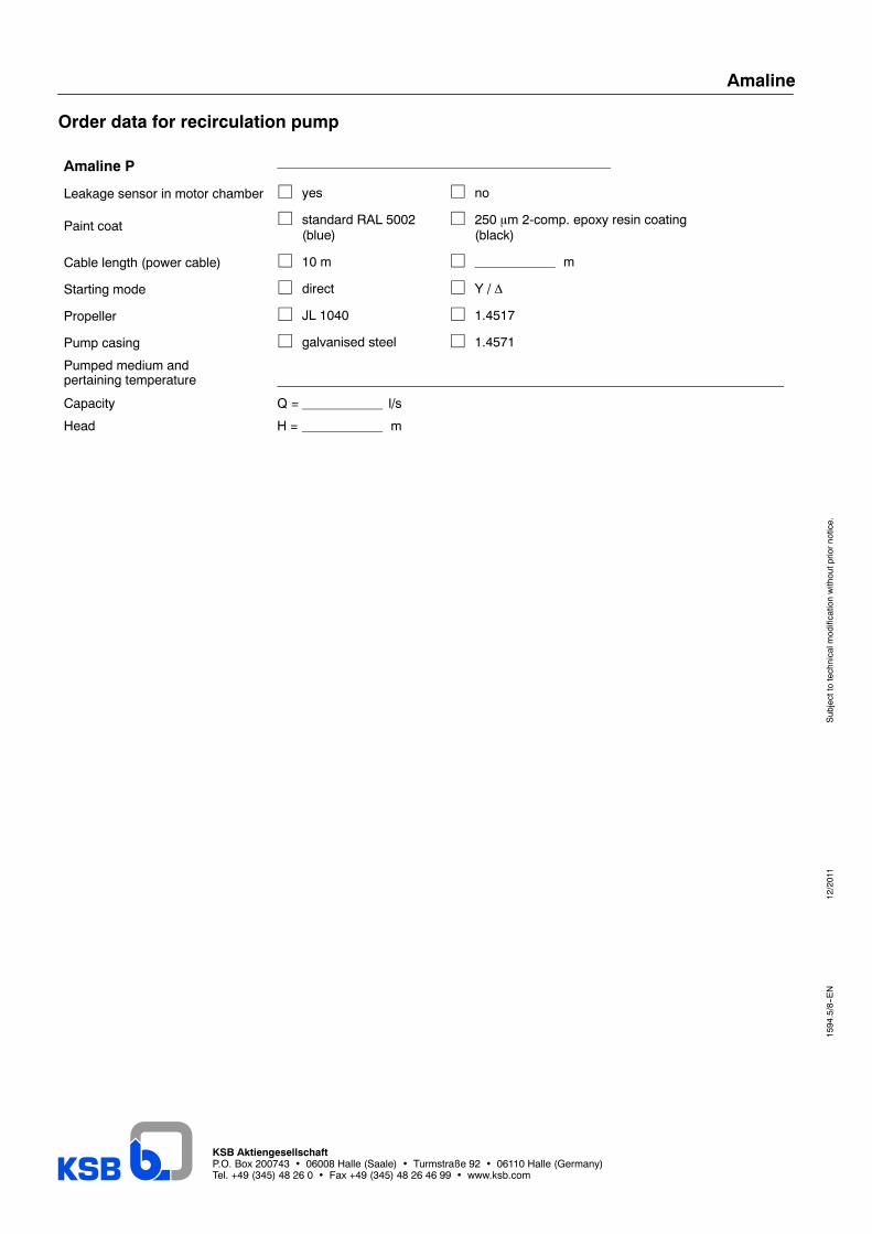
Order data for recirculation pump
Amaline P
Leakage sensor in motor chamber j yes j no
Paint coat j standard RAL 5002(blue)
j 250 mm 2-comp. epoxy resin coating(black)
Cable length (power cable) j 10 m j m
Starting mode j direct j Y / ∆
Propeller j JL 1040 j 1.4517
Pump casing j galvanised steel j 1.4571
Pumped medium andpertaining temperature
Capacity Q = l/s
Head H = m