1512 0539 souriau - camarinewusen01 m-series.pdf · 7 features & benefi ts field proven robust...
TRANSCRIPT

M SeriesUnderwater Connectors
MA
RIN
E SE
RIES

3
Contents
Range Extension
Other Series
Typical applications .......................................... 6Features & Benefi ts .......................................... 7Range overview ................................................ 10
Overview
Double watertightness connectors .................. 42Oil fi lled connectors ......................................... 42 Specifi c shells ................................................... 43Optical M connectors ....................................... 43Size 28M ........................................................... 44High current/High voltage ................................ 44
TP Series ........................................................... 48U Series ............................................................ 488810 Series - Underwater mateable ................. 49
Product description ......................................... 15Technical features ............................................. 17Ordering information........................................ 19 Contacts ........................................................... 21 Contact layouts ................................................ 22Cable clamp accessories .................................. 25 Shell dimensions .............................................. 28 Tools and wiring instructions ............................ 38
Standard Range
M Series | Overview
The M Series connectors meet the highest standards of safety for deep immersion. It is currently used in many applications: from oil and gas industry service to renewable energy generation system and military submarines.
The M Series feature a large range of shell styles, layouts or insulator materials. No matter you need to convey signal information or high power we have the right product or we can make it.
Presentation
Oth
er S
erie
s R
ang
e E
xten
sio
nSt
and
ard
Ran
ge
Ove
rvie
w

MA
RIN
E SE
RIES
© 2016 SOURIAU - SOURIAU is a registratred trademark

5
Overview6
7
8
Typical applications ....................................................................................................
Features & Benefits ....................................................................................................
Range overview ..........................................................................................................
M Series

6
M Series | Overview
Typical applications
Submarines
Towed Streamers
Vessels
Oil and Gas
ROVs & AUVs
Marine Renewable Energies
© C
urra
hees
hutt
er /
Shu
tter
stoc
k
© Iu
rii /
Shu
tter
stoc
k©
Don
vict
ori0
/ F
otol
ia©
U.S
. Arm
y
© A
lexa
ndr
Miti
uc /
Fot
olia
© In
gva
r Tj
osth
eim
/ S
hutt
erst
ock
7
Features & Benefi ts
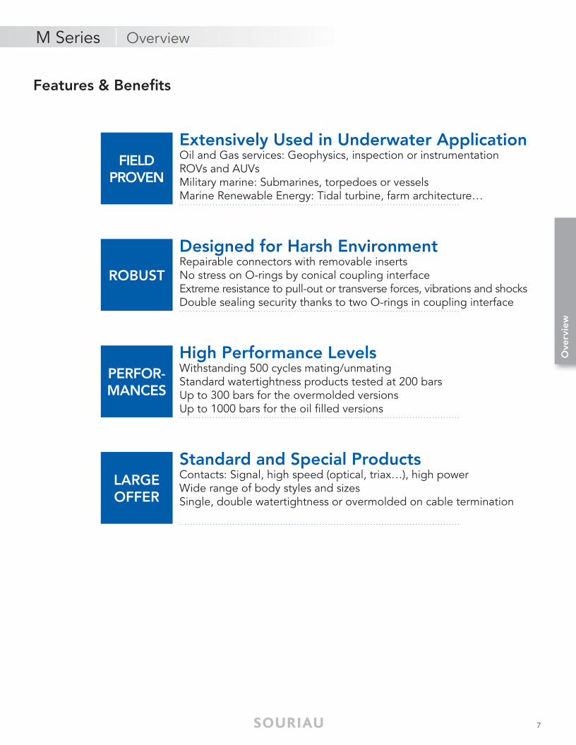
FIELDPROVEN
ROBUST
PERFOR-MANCES
LARGEOFFER
Extensively Used in Underwater ApplicationOil and Gas services: Geophysics, inspection or instrumentationROVs and AUVsMilitary marine: Submarines, torpedoes or vesselsMarine Renewable Energy: Tidal turbine, farm architecture…
Standard and Special ProductsContacts: Signal, high speed (optical, triax…), high powerWide range of body styles and sizesSingle, double watertightness or overmolded on cable termination
High Performance LevelsWithstanding 500 cycles mating/unmating Standard watertightness products tested at 200 barsUp to 300 bars for the overmolded versionsUp to 1000 bars for the oil fi lled versions
Designed for Harsh EnvironmentRepairable connectors with removable insertsNo stress on O-rings by conical coupling interface Extreme resistance to pull-out or transverse forces, vibrations and shocksDouble sealing security thanks to two O-rings in coupling interface
M Series | Overview
Ove
rvie
w
8
M Series | Overview
Features & Benefits
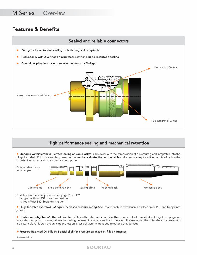
Sealed and reliable connectors
High performance sealing and mechanical retention
M type cable clamp set example
Cable clamp Braid bonding cone Sealing gland
Receptacle insert/shell O-ring
Plug insert/shell O-ring
Packing block Protective boot
O-ring for insert to shell sealing on both plug and receptacle
Redundancy with 2 O-rings on plug taper seat for plug to receptacle sealing
Conical coupling interface to reduce the stress on O-rings
Standard watertightness: Perfect sealing on cable jacket is achieved with the compression of a pressure gland integrated into the plug’s backshell. Robust cable clamp ensures the mechanical retention of the cable and a removable protective boot is added on the backshell for additional sealing and cable support.
2 cable clamp sets are presented on page 25 and 26: A type: Without 360° braid termination M type: With 360° braid termination
Plugs for cable overmold (SA type): Increased pressure rating. Shell shape enables excellent resin adhesion on PUR and Neoprene©
jackets.
Double watertightness*: The solution for cables with outer and inner sheaths. Compared with standard watertightness plugs, an integrated compound housing allows the sealing between the inner sheath and the shell. The sealing on the outer sheath is made with a pressure gland. It provides an extra protection in case of water ingress due to outer jacket damage.
Pressure Balanced Oil Filled*: Special shell for pressure balanced oil filled harnesses.
*Please consult us
Plug mating O-rings

9
Features & Benefi ts
M Series | Overview
Ove
rvie
w
High grade materials for long term immersion
Easy wiring and installation
Shells are manufactured from Nickel Aluminium Bronze which has been specifi cally developed for underwater applications and is proven to be highly corrosion resistant in sea water. This material has excellent electrical conductivity properties and is extremely robust and long lasting.
Good resistance to biological fouling
Insulators are made of PTFE or PCTFE which features near zero water absorption and excellent electrical insulating properties.
O-rings are made from Nitrile for excellent fl uid compatibility (sea water, mineral oil…) and long durability.
Contacts are gold over nickel plated brass.
RoHS compliant.
Scoop proof: No risk of damaging contacts during the coupling operation when using a female plug and a male receptacle.
Removable insulators: To allow easy wiring and replacement in case of wiring mistakes or servicing.
C O M P L I A N T

10
examples
overview
Typical harness
Range
M Series | Overview
Receptacles
Standard range page 15 to 38
Plugs
Feedthrough In-line receptacles
Pressure sealing caps
► RER: Jam nut► REC: Square flange► RECSC: Cable connecting
► FED: Plug► FED (SA or SB): Plug for cable overmolding
► TER: Jam nut feedthrough► TEC: Square flange feedthrough
► PCE: In-line receptacle► PCE (SA or SB): In-line receptacle for external overmolding
► BER: For receptacles, in-line receptacles and feedthroughs► BEF: For plugs
► REC ► FED ► FED ► FED (SA)► TEC

11
examples
overview
Typical harness
Range
M Series | Overview
Ove
rvie
w
► The only limit is your imagination, Consult us!
Range extension page 42 to 48
Various possibilities of range extension & shell variant from standard series
► Fiber optics and Hybrid
► Pressure Balanced Oil Filled
(PBOF)
► Bigger size 28M
► Double Watertightness
► Larger backshell size (GM)
► PCE (SA) ► FED (SA) ► FED (SA) ► RER
► High current/High voltage

12
overviewRange
M Series | Overview
PCE (SA or SB)
PCE
TER
TEC
RDECSC*
RECSC
RER
REC
PCDE*
PCE (PBOF)*
Pressure Balanced Oil Filled
Receptacles
Cable Receptacles
Feedthroughs
In-Line Receptacles

13
overviewRange
M Series | Overview
Ove
rvie
w
FDED*
FED (SA/SB)
FED
FED (PBOF)*
Pressure Balanced Oil Filled
Plugs
*Contact us for more information

MA
RIN
E SE
RIES
© 2016 SOURIAU - SOURIAU is a registratred trademark

15
Standard Range16
17
19
21
22
25
28
38
Product description ....................................................................................................
Technical features .......................................................................................................
Ordering information..................................................................................................
Contacts .....................................................................................................................
Layouts .......................................................................................................................
Cable clamp accessories ............................................................................................
Shell dimensions .........................................................................................................
Tools & Wiring instructions .........................................................................................
M Series

16
Product description
Standard watertightness: Straight plug + Receptacle (mated)
Plug for cable overmolding: FED SA and SB type
1. Receptacle2. Plug3. Insert with sealed contact4. Insert/Shell O 'Ring seal
5. Plug/Receptacle taper seat with O'Ring seal6. Panel/Receptacle O'Ring7. Removable protective boot8. Cable outer sheath/Plug watertightness by packing seal
3. Insert with sealed contact4. Insert/Shell O 'Ring seal5. Plug/Receptacle taper seat with O'Ring seal
6. Poting housing7. Outer sheath cable/Plug watertightness by customer over molding8. Backshell/Plug watertightness by O'Ring seal
M Series | Standard Range
1 6 3
3 4 5 6 7
4 5 2 78

17
Mechanical
• Shell: Nickel aluminium bronze
• Insulator: PTFE (T) PCTFE (K) Other materials are available upon request (Peek, Silicone, PBTFV)
• O-rings: Nitrile elastomer
• Contacts: Brass
• Contacts plating: Gold over nickel plated
• Packing washers and Protection boot: Neoprene Elastomer
• Endurance: 500 mating/unmating operations
• Shock: Static acceleration of 120g on each axis
• Vibration: From 0,1 to 1 Hz: amplitude = 25 mm From 1 to 5 Hz: acceleration = 0.1 g From 5 to 22 Hz: amplitude = 1 mm From 22 to 50 Hz: acceleration = 2 g Duration: 1 hour on each axis
Electrical
• Voltage rating (Vrms)
• Insulation resistance: Unmated connectors : ≥ 104 MΩ Mated connectors : ≥ 5x10³ MΩ on 500 Vcc
• Shielding: Connectors mated: Resistance between the receptacle plate and the plug’s cable braid : ≤ 10 mΩ
• Current rating and contact resistance:
Description• Marine connectors
• Screw coupling
• Sealing between plug and receptacles performed by 2 O-rings
• Standard watertightness: Sealing on cable achieved by packing washers
• Plugs for over molding (SA/SB): Sealing on cable is given by overmolding
Voltage Category
SOURIAU recommendedservice voltage (Vrms 50 Hz)
DielectricWithstanding Voltage (Vrms
50Hz)
Service 0 350 1000Service 1 600 1500Service 2 1000 2300Service 3 1500 3200Service 4 5000 10000Service 5 7000 15000
Shell size
Contact sizeCurrent
rating per contact (A)
Contact resistance
(mΩ)
9M10M14M20M24M
20 7 ≤ 416 14 ≤ 314 20 ≤ 2.512 26 ≤ 26 65 ≤ 12 115 ≤ 0.6
24M 120 MC 600 ≤ 0.0310M14M
High voltage 14 ≤ 3
20M High voltage 20 ≤ 2.5
10MCoaxial 50Ω 20 ≤ 2.5Coaxial 75Ω 7 ≤ 4
10M Triaxial 50Ω7 ≤ 4
20M Coaxial 50Ω10M Triaxial 75Ω
4 ≤ 520M Coaxial 75Ω
14MCoaxial 50Ω 40 ≤ 1.5Triaxial 50Ω 26 ≤ 2Triaxial 75Ω 14 ≤ 3
Technical features
M Series | Standard Range
Stan
dar
d R
ang
e

18
Environmental
• Operating temperature range: - 20°C to + 70°C
• Watertightness - Mated:
- Unmated:
(1) Size 9M 50 bar(2) Size 9M 60 bar
• Salt spray - 10 x (24h + 24h) alternate salt spray according to EN60068-2-11 - 500h continuous salt spray according to NFC93422
• Fluids Resistance - Oil, alcohol, petrol, diesel fuel, sea water - Various gases (natural, butane, propane, Freon) - Various acids (acetic, boric, citric)
Type Standard SA/SB
Operating pressure
≤ 100 bar ≤ 300 bar
Test 200 barPressure following
customer spec.
Type PTFE inserts PCTFE inserts
Operating pressure
30 bar 60 bar(1)
Test pressure
40 bar 75 bar(2)
M Series | Standard Range

19
Ordering information
Product builder
N° Criterias Choices Pages
1 Wires type and gauge Minimum contact size 21
2 Number of contact to connect Contacts layout 22
3 Electrical characteristics Layout and shell size 17
4 Cable diameters Size checking 25
5 External pressure Sealing type 18
6 Unmated pressure Insert material 18
7 Cable type and construction/Braid termination Cable clamp set 25
8 General confi guration Shell type 12 and 13
Recommendations
Standard watertightness M Series connectorsWatertightness is given by a packing-block. Watertightness performances will depend on cable quality:. Hardness (shore A hardness > 70 is recommended). Cylindricity and circularity . Roughness. Cable outer diameter tolerance (maximum tolerance of 1 mm on outer diameter is recommended)
Wiring chamber potting operation is necessary for pressure higher than 30 bar.See page 38 for potting tools.
Overmolded plugsWatertightness is achieved by resin overmolding. Conductor insulation and jacket material (preferably Neoprene® or Polyurethane) of specifi ed cable determines overmold material specifi cation.Watertightness is determined by the adhesion of the overmold material to the cable.
M Series | Standard Range
Stan
dar
d R
ang
e

20
Basic Series PCE M 14M T 04 12 A 105
Shell typeRER: Jam-nut receptacleREC: Screws mounting receptacleFED: Straight plugPCE: In-line receptacleRECSC: Screws mounting cable connecting receptacleTER: Jam-nut feedthroughTEC: Screws mounting feedthrough
Type of contacts M: Pin contactF: Socket contacts1: Pin/Socket (for TEC and TER feedthroughs only)
Shell size9M, 10M, 14M, 20M, 24M
Insert materialT: PTFEorK: PCTFE
Contact layoutsSee layout tables page 22
Cable clamp codeStandard watertightness: : (nothing for RER, REC, TER & TEC)A: Without 360° braid terminationM: With 360° braid terminationOvermolding: (nothing for RER, REC, TER & TEC)SA: Without 360° braid terminationSB: With 360° braid termination
Maximum cable outer diameter (in tenth of mm, adjusted at upper five tenth). Example: For a 9.2mm outer diameter cable, the code is 095.Cable code for coaxial, tri-axial, high voltage (Please consult us for coding)Nothing for RER, REC, TER & TEC
M Series connectors part numbers
Pressure sealing cap part numbers
Basic Series BER C 14M
Cap type BER: For receptacles, in-line receptacles and feedthroughsBEF: For plugs
Cable clamp setC: With cord -: Without cord (no mention)
Shell size9M, 10M, 14M, 20M, 24M
M Series | Standard Range

21
Contacts - Size 2 to 20
Shell size Contact sizeØ A (mm)
Active contact OD
Ø F (mm) Contact
Termination ODGauge AWG Section (mm2) Defi nition
9M
20 1,02 0,9 26 to 22 0,14 to 0,38
16 1,59 1,2 24 to 20 0,21 to 0,60
10M
14M
20M
24M
20 1,02 0,9 26 to 22 0,14 to 0,38
16 1,59 1,4 22 to 18 0,38 to 0,93
14 1,92 1,87 18 to 16 0,93 to 1,34
12 2,38 2,3 16 to 14 1,34 to 1,91
6 5 6,2 8 to 6 8,98 to 13,4
2 7 9 4 to 2 21,8 to 34,5
Shell size Contact size Ø A (mm) Ø F (mm)Recommended cable
(Please consult us)
10M
Coaxial 50Ω 1,93 2,4KX 4 - KX 15 - NFC 93550
RG 213 U - RG 58 CUMIL C 17 F
Coaxial 75Ω 1,02 1,5KX 6A - KX 8 - NF C 93550
RG 59 BU - RG 11 AU MIL C 17 F
14M Coaxial 50Ω 3,98 3 KX 13 - NF C 93550MIL C 17 F - RG 217U(1)
10M Triaxial 50Ω
0,9 1,2 KX 15 - NF C 93550MIL C 17 F - RG 58 CU(1)
20-24M Coaxial 50Ω
20-24M Coaxial 75Ω 0,7 0,8 KX 6A - NF C 93550MIL C 17 F - RG 59 BU
14M
Triaxial 50Ω 3 2,6Depending on the cable clamp accessories, please consult us (1)
Triaxial 75Ω 1,59 1,4
Contacts - Coaxial, triaxial
M Series | Standard Range
Pin
Socket
Socket
Pin
Socket
Pin
SocketØ
F
ØF
ØF
ØF
ØA
Pin ØF
ØA
ØF
ØA
Stan
dar
d R
ang
e

22
Contact layouts
Size 9M Layout caption
Size 10M
M Series | Standard Range
0320
3#20Service 2
0720
7#20 Service 1
0920
9#20 Service 0
0416
4#16Service 2
0516
Layout IDfor part numbering
5#16Service 1
0214
2#14Service 2
0314
3#14Service 2
1TX50*
Triax#50ΩService 1
1Coax# 50Ω or 75ΩService 1
0416
4#16Service 2
0720
7#20Service 1
*Please consult us for coax and triax layouts
Contact TypeCoax. Triax.
1CX50* 1CX75*
Number of contacts #SizeVoltage Service Rating

23
Contact layouts
Size 14M
Size 20M
*Please consult us for coax and triax layouts
M Series | Standard Range
19201216
0412
3#12Service 2
0714
4#12Service 2
7#14Service 2
0312
1#06Service 2
1CX50*
1Triax 50Ω#75Service 2
0106
1Coax#50Service 2
1TX50*1TX75*
19#20Service 1
12#16Service 2
4120
41#20Service 1
2716
27#16Service 1
3216
32#16Service 1
2114
21#14Service 1
0712
7#12Service 2
1612
16#12Service 2
0406
4#06Service 2
0306
3#06Service 2
1#02Service 2
0102
4Coax#50Ω or 75ΩService 1
4C50* 4C77*
Stan
dar
d R
ang
e
Contact TypeCoax. Triax.

24
M Series | Standard Range
Contact layouts
Size 24M
*Please consult us for coax and triax layouts
6116
61#16Service 1
4816
48#16Service 1
0616
6#16Service 4
3714
37#14Service 2
2712
27#12Service 2
0402
4#02Service 2
0306
3#06Service 2
3#02Service 2
0302
Contact TypeCoax. Triax.

25
M Series | Standard Range
Cable clamp kits - Selection guide
ConnectorsCableCode
Description
Acceptable cable outer diameter
9M 10M 14M 20M 24M
Single Watertightness
A Standard cable clamp without 360° shield termination 4-6.5 5-11 8-16 14-26 20-31
M Tapper cable clamp with 360° shield termination 4-6.5 5-10.5 9-16 12-24 18-32
External overmolding
SA Overmolding backshell without 360° shield termination < 6.5 < 10.5 < 16.5 < 24.5 < 32
SB Overmolding backshell with 360° shield termination < 6 < 9 < 15 < 17.5 < 26.5
For coaxial, triaxial and high voltage contact layouts, please send us your cable datasheet to defi ne the right cable clamp code
Stan
dar
d R
ang
e

26
Standard watertightness - Cable clamp kits
BA Insulating ring JPE Rubber washer EEN Spacer nut DOS Outer sleeve
CPI Collet clamp MDP Protective boot ESC Cabling spacer RGA Packing washer
CSC Shielding tapper PSC Cable collet RGR Packing block SCA Half collar (+ screws)
Cable clamp code
Grounding Size
A No
9M
10M14M20M
24M
M Yes
9M
10M
14M
20M
24M
M Series | Standard Range

27
Shell dimensions
RER - Jam-nut receptacle, watertight mounting
Shell size 9M 10M 14M 20M 24M
A 22 37 37 49,5 58
B 7 14 13 17 20
Ø E (ISO) M17 x 1 M21 x 1 M29 x 1 M41 x 1 M56 x 1.5
Ø F (ISO) M13 x 0.7 M18 x 0.75 M25 x 0.75 M36 x 1 M46 x 1.5
Ø G 20 25 34 46 64
H Max. 4 10 9 12 14
On fl ats J 15 22 30 41 56
Ø K 13.2 18.2 25.2 36.2 46.2
M 12.2 16.2 23.2 33.2 42.2
N 3 4 4 5 6
Average mass (g)* Consult us 63 110 282 Consult us
M Series | Standard Range
*Average mass estimated by CAD
Note: All dimensions are in millimeters (mm)
0.1 K
0.2M
ax. t
o 45
°
H Max.
A
B
On fl ats J
NØM
ØK
0+
0.1
ØE
ØF
ØG
Panel cut-out
Stan
dar
d R
ang
e

28
Shell dimensions
REC - Square fl ange receptacle, watertight mounting
Shell size 9M 10M 14M 20M 24M
A 22 37 37 49.5 58
B 6.3 14 13 17 20
C 29 32 40 52 76
D 20 24 31 42 60
Ø E (ISO) M17 x 1 M21 x 1 M29 x 1 M41 x 1 M56 x 1.5
Ø F 13 18 25 36 46
Ø K 13.2 18.2 25.2 36.2 46.2
Ø L 4.5 4.3 5.3 6.3 8.5
P 4 5 6 8 9
Ø Q Max. 40.5 42.5 53.5 69.5 100.5
R (ISO) M4 M4 M5 M6 M8
Average mass (g)* Consult us 78 133 337 739
M Series | Standard Range
*Average mass estimated by CAD
Note: All dimensions are in millimeters (mm)
0.2M
ax. t
o 45
°
A
C
ØF
ØE
C
D
DD
D
B P
0.1 K
ØQ
Holes ØL4 blind threaded holes
Panel cut-out
ØK
0+
0.1

29
Shell dimensions
FED - Straight plug
Shell size 9M 10M 14M 20M 24M
Ø A 20 25 34 46.5 68
Ø B Max. 19 23 32 45 66
C 53 73 92 115 205
D 79 110 144 186 315
On fl ats J 17.46 (11/16’’) 22 30 42 54
On fl ats S 12 16 20 30 54
Average mass (g)* Consult us 141 334 822 3170
M Series | Standard Range
*Average mass estimated by CAD
Note: All dimensions are in millimeters (mm)
Stan
dar
d R
ang
e
Shell size: 9M - 10M - 14M - 20M
Shell size: 24M
D
C On fl ats S
On fl ats J ØB MaxØA
DC
On fl ats J On fl ats S ØB MaxØA

30
Shell dimensions
PCE - In-line receptacle
Shell size 9M 10M 14M 20M 24M
Ø A 19 23 31 43 68
Ø B Max. 20 23 32 45 66
C 57 82 100 127 220
D 84 120 153 198 335
Ø E (ISO) M17 x 1 M21 x 1 M29 x 1 M41 x 1 M56 x 1.5
On fl ats J 17 20 28 38 54
On fl ats S 12 16 20 30 54
Average mass (g)* Consult us 160 359 888 3491
M Series | Standard Range
*Average mass estimated by CAD
Note: All dimensions are in millimeters (mm)
Shell size: 9M - 10M - 14M - 20M
Shell size: 24M
D
D
C
C
On fl ats J
On fl ats J
On fl ats S ØB Max
ØB Max
ØA
ØA
ØE
ØE

31
Shell dimensions
RECSC - Square fl ange cable connecting receptacle
Shell size 9M 10M 14M 20M 24M
A 57 82 100 127 220
B 42 58 76 97 170
C 32 40 52 76 96
D 24 31 42 60 70
Ø E M17 x 1 M21 x 1 M29 x 1 M41 x 1 M56 x 1.5
Ø F 18 22 29 41 69
G 84 120 153 198 335
H Max. 10 12 12 20 /
Ø J Max. 20 23 32 45 66
Ø J1 Max. 17 20 27 39 54
Ø K 18.2 22.2 29.2 41.2 69.2
Ø L 4.3 5.3 6.3 8.5 12.5
P 4 8 8 9 12
Ø Q Max. 42.5 53.5 69.5 100.5 119.5
R M4 M5 M6 M8 M12
On fl ats J 12 16 20 30 54
Average mass (g)* Consult us 224 462 Consult us 3074
M Series | Standard Range
*Average mass estimated by CAD
Note: All dimensions are in millimeters (mm)
D
D
D
DC
C
GA
B POn fl ats S
0.1
K
4 holes ØL4
blin
d t
hrea
ded
hol
es
M Max
ØQ
ØFØJ MaxØJ1 Max
0.2M
ax. t
o 45
°
ØE
Stan
dar
d R
ang
e
ØK
0+
0.1
Panel cut-out

32
Shell dimensions
FED Plug and PCE in-line receptacles for cable overmolding - SA and SB versions
Shell size 9M 10M 14M 20M 24M
Ø A / Ø A1 20/19 25/23 34/31 46/43 68/68
Ø B 17.5 22 30 42 58
C 45 63 73 88 132
D 15.5 15.5 18.5 20.5 30.5
E 49 73 83 100 151
Ø F 14 17.5 23.5 32 42
G 11 20 25 29.5 45
On fl ats J On fl ats J1 17.46/17 22/20 30/28 42/38 54/54
S sur plats/On fl ats S 12 15 21 29 38
Average mass (g)* Consult us Consult us 195/220 454/Consult us 1335/1569
M Series | Standard Range
*Average mass estimated by CAD
Note: All dimensions are in millimeters (mm)
C
C
E E
G
G
On fl ats JOn fl ats J
On fl ats J1On fl ats J1 On fl ats SOn fl ats S
D
D
ØF
ØF
ØA
ØBØB ØA1ØA1
ØA
Shell size: 9M - 10M - 14M - 20M Shell size: 24M
FED PCE

33
Shell dimensions
TER - Jam-nut feedthrough
Shell size 9M 10M 14M 20M 24M
A 50 60 60 82 98
B 34.5 35.5 34.5 47.5 57
Ø E (ISO) M17 x 1 M21 x 1 M29 x 1 M41 x 1 M56 x 1.5
Ø G 23 28 40 52 70
H Max. 19 16 13 22 23
On fl ats J 20 24 34 46 63
Ø K 17.2 21.2 29.2 41.2 56.2
M 14.2 19.2 27.2 39.2 50.2
N 4 4 6 5 8
Average mass (g)* Consult us 113 222 Consult us Consult us
M Series | Standard Range
*Average mass estimated by CAD
Panel cut-out
Note: All dimensions are in millimeters (mm)
Stan
dar
d R
ang
e
ØM
H Max.
0.2M
ax. t
o 45
°
0.1 K
ØG
ØE
ØE
Use
Soc
ket
plu
g(1
)
Use
Pin
plu
g(1
)
On fl ats J
A
B
N
ØK
0+
0.1

34
Shell dimensions
TEC - Square fl ange feedthrough
Shell size 9M 10M 14M 20M 24M
A 50 60 60 82 98
B 34.5 35.5 34.5 47.5 57
C 32 40 52 76 76
D 24 31 42 60 60
Ø E (ISO) M17 x 1 M21 x 1 M29 x 1 M41 x 1 M56 x 1.5
H Max. 23 20 19 27 31
K 17.2 21.2 29.2 41.2 56.2
Ø L 4.3 5.3 6.3 8.5 8.5
P 4 6 8 9 12
Ø Q Max. 42.5 53.5 69.5 100.5 100.5
R (ISO) M4 M5 M6 M8 M8
Average mass (g)* Consult us Consult us 299 Consult us Consult us
M Series | Standard Range
*Average mass estimated by CAD
A
0.2M
ax. t
o 45
°
H Max.
D4
blin
d t
hrea
ded
hol
es0.
1 K
CØQ
4 holes ØL
C
D
D
B P
ØE
Use
mal
e p
lug
(1)
Use
fem
ale
plu
g(1
)
ØE
Panel cut-out
Note: All dimensions are in millimeters (mm)
*Average mass estimated by CAD
ØK
0+
0.1

35
Shell dimensions
M Series | Standard Range
Pressure sealing caps
Mated/Unmated connectors
Shell size 9M 10M 14M 20M 24M
A 30 39 40 52.5 71
Ø B 19 23 31 43 64
C 27.5 34 34 47.5 69
Ø D 20 25 34 46.5 68
On fl ats J 17 20 28 38 54
On fl ats S 17,46 22 30 42 54
R = Mated shells overlap
BEF - Cap for plug BER - Cap for receptacle
R
On fl ats S
C
240
Ø D
On fl ats J
A
240
Ø B
Note: All dimensions are in millimeters (mm)
Stan
dar
d R
ang
e
Shell size 9M 10M 14M 20M 24M
R 11 19 19 25 32

36
Insert + Contacts sub assemblies part numbers
Cable clamp kits part numbers
Insert + Contacts Sub Assembly BIS 14M T 04 12 M
Shell type:9M, 10M, 14M, 20M, 24M
Insert materialT: PTFEK: PCTFE for standard layouts
Contact layoutsSee layout tables
Type of contacts M: Pin contactsF: Socket contacts
Kit type: See page 26RAE: Full cable clamp kitRAER: Cable clamp kit sub assembly
RAE 14M A 100
Shell size:9M, 10M, 14M, 20M, 24M
Cable clamp CodeStandard watertightness: (nothing for RER, REC, TER & TEC)A: Without 360° braid terminationM: With 360° braid termination
Maximum cable outer diameter (in tenth of mm, adjusted at upper five tenth). Example: For a 9.2mm outer diameter cable, the code is 095.Cable code for coaxial, tri-axial, high voltage & double watertightness (consult us for coding)
M Series | Standard Range

37
M Series | Standard Range
O-rings part numbers
O-ring Type 9M 10M 14M 20M 24M
� Panel O-ring (for REC-RER) 09-01 10-01 14-01 20-01 24-01
� Insulator/Shell O-ring 09-02 10-02 14-02 20-02 24-02
� Taper seat O-rings 09-03 10-03 14-03 20-03 24-03
� Panel O-rings (for TEC-TER) 09-04 10-04 14-04 20-04 24-04
� Panel O-ring (for RECSC) 10-01 20-02 14-05 20-04 24-05
1 2 3 2 2
REC-RER Receptacles FED Plug PCE Cable connecting plug
2 4 3 2 5
TEC-TER Bulkhead BER Cap RECSC Square flange in-line receptacle
Stan
dar
d R
ang
e

38
Tools
Contact type Tool P/N
Male size 6 OUT.BMV.20M.16MC
Female size 6 OUT.BFV.20M.16MC
Male size 2 OUT.BMV.20M.35MC
Female size 2 OUT.BFV.20M.35MC
10M triaxial 50 Ω - 75 Ω24/20M coaxial 50 Ω - 75 ΩMale and female
OUT.MC.04
M Series | Standard Range
Contact assembling toolThe removable contacts are held in the insert by a special nut, which can be screwed or unscrewed, using the tools below
The wiring and installation instruction for M Series connectors can be provided upon request.
P.N : OUT 050W5031B5 (20M)OUT 050W5003B5 (24M)
End wrenchesUsed to tighten coupling ring of size 20M or 24M with a torque wrench
7
20
Plastic jaw plierThis tool is used for holding the cable clamp while tightening the sleeve
P/N : 410.01
Plug wiring toolsThese tools are used to maintain correctly plugs during the final operation of wiring: tightening the tightening sleeve
Size Tool P/N
10M OUT330 10M
14M OUT330 14M
20M OUT330 20M
24M MA5W4001A9
Plug Size Tool P/N
9M MA1W6010B5
10M MA2W6010B5
14M MA3W6010B5
20M MA4W6010B5
24M MA5W6010B5
Potting toolUsed to fill with resin cabling spacers

39
M Series | Standard Range
Notes
Stan
dar
d R
ang
e

MA
RIN
E SE
RIES
© 2016 SOURIAU - SOURIAU is a registratred trademark

41
Range ExtensionM Series
41
42
43
43
44
44
Double watertightness connectors .............................................................................
Oil filled connectors ...................................................................................................
Specific shell types .....................................................................................................
Optical M connectors .................................................................................................
Size 28M and bigger shell sizes..................................................................................
High current/High voltage ..........................................................................................

42
Product range extension
M Series | Range Extension
For more information, please consult us
Double Watertightness
The solution for the highest safety with double armored cables.
A double watertightness solution: . Sealing between the cable outer sheath and the backshell thanks to a sealing gland. . Sealing between the cable inner sheath and the backshell thanks to potting.
Provides an extra sealing protection in case of water ingress due to outer jacket damage
PBOF: Oil Filled Plug and In-line Receptacle
The solution for very deep immersion with oil filled cables.
High pressure withstand: . Up to 1000 bars . Dielectric oil filling . Balances out the pressure difference . Water cannot enter the plug shell when the cable is damaged
For more information, please consult us
For more information, please consult us

43
Product range extension
GM RangeLarger Backshell Size
Optical M Connectors
Plugs and in-line receptacle with magnifiedbackshells for larger than standard cable mounting.
Watertight up to 100bar for optical or hybrid connectors. Based on three existing shells, 14MO, 20MO and 24MO.
Size 10GM 14GM 20GM 24GM
Maxi cable OD(mm) 14 19 28,5 40
M Series | Range Extension
For more information, please consult us
For more information, please consult us
Ran
ge
Ext
ensi
on

44
Product range extension
Size 28
The biggest M Series connector size.
Special layouts: . Up to 126 contacts . Coax and hybrid layouts . High power. Up to 3 x 290A
M Series | Range Extension
High Current and High Voltage
High current and high voltage layouts can be available upon request.
High voltage . Up to 15 000VRMS (Dielectric Withstanding Voltage at 50 Hz)
High current . Up to 600A with 120 mm2 contacts
For more information, please consult us
For more information, please consult us

45
Notes
M Series | Range Extension
Ran
ge
Ext
ensi
on

MA
RIN
E SE
RIES
© 2016 SOURIAU - SOURIAU is a registratred trademark

47
Other SeriesM Series
48
48
49
TP Series .....................................................................................................................
U Series ......................................................................................................................
8810 Series .................................................................................................................

48
Other Series
TP Series
U Series
Economic connectors similar to M Series with nickel plated brass shells and PA6/6 molded inserts.See specific catalog available online.
Sealed: . Down to 300 meters depth
Large range: . 4 shell sizes: 8TP, 10TP, 14TP and 20TP . Receptacles, cable receptacles, plugs and feedthroughs. . Signal, power, high voltage, coax and triax contacts
Economic underwater solution
RoHS compliant
Connectors similar to M Series with 316L stainless steel shells and FPM seals.See specific catalog.
High pressure withstand:
. Down to 300 meters depth
Robust: . High corrosion resistant stainless steel shell (AISI 316L) . Robust screw coupling mechanism . High temperature resistance (up to 170°C with PTFE insulators) . Nylatron, Teflon or Tefzel insulators . Radiation withstanding (up to 100 MRads)
RoHS compliant
M Series | Other Series
C O M P L I A N T
C O M P L I A N T

49
Other Series
8810 Series
Wet/underwater mateable connectors for deep immersion. See specific catalog available online.
High pressure withstand: . Down to 3000 meters depth
Robust: . Marine bronze shells . Robust screw coupling mechanism
RoHS compliant
M Series | Other Series
Oth
er S
erie
s
C O M P L I A N T

50
M Series | Other Series
Notes


WC
AM
ARI
NEW
USE
N01
© C
opyr
ight
SO
URI
AU
Jan
201
6 -
SOU
RIA
U is
a r
egis
tere
d t
rad
emar
k A
ll in
form
atio
n in
thi
s d
ocum
ent
pre
sent
s on
ly g
ener
al p
artic
ular
s an
d s
hall
not
form
par
t of
any
con
trac
t. A
ll rig
hts
rese
rved
to
SOU
RIA
U fo
r ch
ang
es w
ithou
t p
rior
notifi
catio
n or
pub
lic a
nnou
ncem
ent.
Any
dup
licat
ion
is p
rohi
bite
d, u
nles
s ap
pro
ved
in w
ritin
g.
Your local contact
10-31-1299
Promoting sustainable forest management
www.pefc.org
Our contribution to environmental protection:This catalog is printed on PEFC certified paperAdvancement of sustainablewood cultivation. www.pefc.org
Reliable People, Reliable Solutions