1500psi 1l botanical oil extraction system owner...
TRANSCRIPT

1500PSI 1L BOTANICAL OIL
EXTRACTION SYSTEM OWNER’S MANUAL
WARNING FAILURE TO FOLLOW THE SETUP AND OPERATION PROCEDURE PROVIDED IN WITHIN THIS MANUAL MAY VOID THE EXTRACTION SYSTEM’S WARRANTY
Apeks LLC 150 Commerce Blvd. Johnstown OH 43031
844-IGO-4CO2 (844-446-4262) www.apekssupercritical.com
Scan this QR code to get the most recent version of this manual!
Updated 4/22/2016 Copyright Apeks LLC, 2014
2
Table of Contents 1. Critical Safety Overview .........................................................................................................4
2. Unpacking Instructions ...........................................................................................................5
2.1. Shipping Crate Inspection................................................................................................5
2.2. Unpacking Instructions ....................................................................................................6
3. System Requirements ............................................................................................................9
3.1. General System Specifications ........................................................................................9
3.2. Facility .............................................................................................................................9
3.3. Electrical ..........................................................................................................................9
3.4. Recirculating Water Chiller/Heater ................................................................................ 10
4. Setup and Assembly ............................................................................................................ 10
4.1. Leveling Feet ................................................................................................................. 10
4.2. Coolant Connections ..................................................................................................... 11
4.3. CO2 Connections ........................................................................................................... 12
4.4. Electrical Connections ................................................................................................... 14
5. System Operation ................................................................................................................ 17
5.1. 1500-1L Overview ......................................................................................................... 17
5.2. Pre-Cleaning .................................................................................................................. 18
5.3. Opening Extraction Vessel ............................................................................................ 18
5.4. Loading Botanical or Other Media ................................................................................. 19
5.5. Closing Extraction Vessel .............................................................................................. 19
5.6. Chiller Start Up .............................................................................................................. 19
5.7. Conducting an Extraction............................................................................................... 20
5.8. Venting the System Prior to Opening ............................................................................ 22
5.9. Cleaning Between Runs ................................................................................................ 23
5.10. What to Expect During an Extraction .......................................................................... 24
6. Troubleshooting ................................................................................................................... 24
6.1. Ice On Separator ........................................................................................................... 24
6.2. Pump does not turn on .................................................................................................. 24
6.3. Low Extractor Pressure (Due to Low Separator Pressure) ............................................ 25
6.4. Low Extractor Pressure (Due to Low Bottle Pressure) .................................................. 25
6.5. Low Extractor Pressure (Due to Worn Pump Seals) ...................................................... 25
6.6. Non-Uniform Extractor Pressure Gauges (Due to Clogged Extractor Filter) .................. 25
6.7. Extractor Overpressure ................................................................................................. 26
Updated 4/22/2016 Copyright Apeks LLC, 2014
3
6.8. Extractor Overpressure (Due to High Separator Pressure) ........................................... 26
6.9. Extractor Overpressure (Due to Clogged Orifice) .......................................................... 26
6.10. Separator Overpressure (Due to Clogged Coalescing Filter) ..................................... 27
6.11. Reset Button............................................................................................................... 27
7. System Maintenance ............................................................................................................ 29
7.1. Replacing or cleaning the coalescing filter cartridge ...................................................... 30
Appendix A. 1500-1L Piping and Instrumentation Diagram ........................................................ 33
Appendix B. 1500-1L Electrical Control Diagram ........................................................................ 35
Appendix C. CO2 Pump Rebuild Instructions .............................................................................. 37
Appendix D. Pre-Training Checklist ............................................................................................ 43
References ................................................................................................................................. 44
Updated 4/22/2016 Copyright Apeks LLC, 2014
4
1. Critical Safety Overview
Throughout these instructions, this symbol is used to indicate that the instructions are critically important to your safety and the safety of your system. Failure to follow the instructions as written can result in a rapid release of high pressure CO2 potentially causing equipment or personnel damage.
WARNING Subcritical and Supercritical CO2 systems operate under high pressure. Operators must be fully trained and familiar with the system. Failure to operate the system can result in equipment damage and/or bodily injury.
WARNING Subcritical and Supercritical CO2 systems use large amounts of CO2 during operation. Ensure that system is installed in a well-ventilated area to prevent buildup of CO2 which can cause asphyxiation. Use of a CO2 monitor is strongly recommended.
WARNING Opening a vessel under pressure can result in a rapid release of pressure and ejection of the material inside the vessel. DO NOT ATTEMPT TO OPEN A VESSEL UNDER PRESSURE! Always make sure a vent path for the vessel is opened and the corresponding pressure gage reads zero prior to loosening the vessel closure bolts.
WARNING Subcritical and Supercritical CO2 systems are designed to operate in doors. Extreme temperatures (below 50°F and above 85°F) will negatively impact the functionality of the system. The environmental temperature range is for the system, chiller, pump and CO2 bottles.
WARNING Only use Propylene Glycol and distilled water in the chiller and cooling system. Never use Deionized Water in the chiller or cooling system.
WARNING Never turn on the chiller without the thermocouple probe installed and connected to the chiller.
Updated 4/22/2016 Copyright Apeks LLC, 2014
5
2. Unpacking Instructions
Apeks 1500-1L systems are shipped in a single crate containing the chiller, high pressure CO2 pump and botanical extraction system. Following are the steps for removing the system from the crate and setting it up for initial use.
2.1. Shipping Crate Inspection Prior to accepting the crate, ensure that the crating material is similar to the pictures shown below. Also, please verify that that there is no external damage to the wood crate. If damage is found, do not accept the delivery from the shipping company. IF ACCEPTNG MINOR DAMAGED CRATE, WRITE ON ALL SHIPPING DOCUMENTS MINOR DAMAGE FOUND ON CRATE. Additionally, call Apeks at 844-446-4262 to report damage and take pictures of each damaged location.
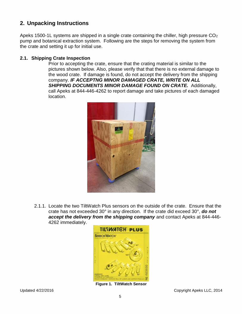
2.1.1. Locate the two TiltWatch Plus sensors on the outside of the crate. Ensure that the
crate has not exceeded 30° in any direction. If the crate did exceed 30°, do not accept the delivery from the shipping company and contact Apeks at 844-446-4262 immediately.
Figure 1. TiltWatch Sensor
Updated 4/22/2016 Copyright Apeks LLC, 2014
6
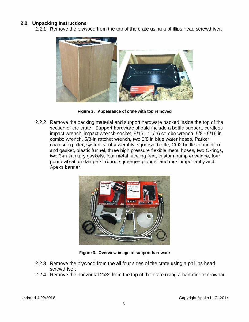
2.2. Unpacking Instructions 2.2.1. Remove the plywood from the top of the crate using a phillips head screwdriver.
Figure 2. Appearance of crate with top removed
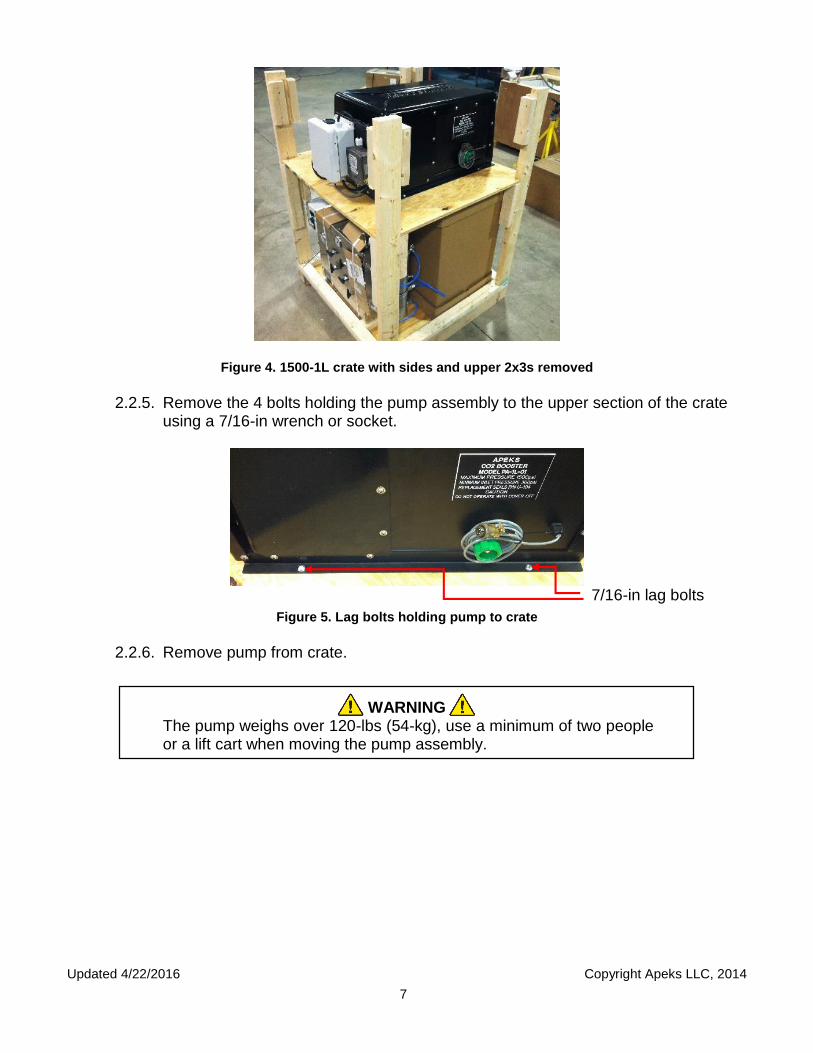
2.2.2. Remove the packing material and support hardware packed inside the top of the
section of the crate. Support hardware should include a bottle support, cordless impact wrench, impact wrench socket, 9/16 - 11/16 combo wrench, 5/8 - 9/16 in combo wrench, 5/8-in ratchet wrench, two 3/8 in blue water hoses, Parker coalescing filter, system vent assembly, squeeze bottle, CO2 bottle connection and gasket, plastic funnel, three high pressure flexible metal hoses, two O-rings, two 3-in sanitary gaskets, four metal leveling feet, custom pump envelope, four pump vibration dampers, round squeegee plunger and most importantly and Apeks banner.
Figure 3. Overview image of support hardware
2.2.3. Remove the plywood from the all four sides of the crate using a phillips head
screwdriver. 2.2.4. Remove the horizontal 2x3s from the top of the crate using a hammer or crowbar.
Updated 4/22/2016 Copyright Apeks LLC, 2014
7
Figure 4. 1500-1L crate with sides and upper 2x3s removed
2.2.5. Remove the 4 bolts holding the pump assembly to the upper section of the crate
using a 7/16-in wrench or socket.
Figure 5. Lag bolts holding pump to crate
2.2.6. Remove pump from crate.
WARNING The pump weighs over 120-lbs (54-kg), use a minimum of two people or a lift cart when moving the pump assembly.
7/16-in lag bolts

Updated 4/22/2016 Copyright Apeks LLC, 2014
8
2.2.7. Remove the upper compartment plywood using a phillips head screwdriver.
Figure 6. 1500-1L crate with upper section plywood removed
2.2.8. Remove the vertical supports from the crate using a hammer or crowbar. 2.2.9. Remove the chiller (in cardboard box) from the crate.
WARNING The chiller weighs over 120-lbs, use a minimum of two people or a lift cart when moving the chiller assembly.
2.2.10. Use a pair of diagonal cutters or tin snips to cut the banding holding the
extraction system to the crate.
Figure 7. Appearance of 1500-1L extraction system after banding removal
2.2.11. Retain the crate and all packing materials for future shipping should the system
ever need to be moved to another facility or shipped back to Apeks.

Updated 4/22/2016 Copyright Apeks LLC, 2014
9
Pump Unit
CompleteGoes with Voltage Phase Full Load Amps Recommended connection
1L systems 115VAC 1 16 20A 115VAC wall receptacle. NO GFI
Diaphragm Systems
Chiller size Goes with Voltage Phase Full Load Amps from Polyscience manualPolyscience recommended
connection1/4HP 1L systems 115VAC 1 12.5 NEMA 5-15R wall receptacle. NO GFI
3/4HP
5000PSI automated
systems, diaphragm
systems with small (7.5-
10HP) compressor
230VAC 1 12.2 NEMA 6-15R receptacle
1.5HP
Large (12.5HP) diaphragm
compressor systems (eff
10/15/2015)
230VAC 1 31.4Field wired- Polyscience recommends
40Amp dedicated hard wired circuit
Control Panel Goes with Voltage Phase Main Fuse or breaker size Apeks recommended connection
1L 115VAC 1 10ANEMA 5-15R wall receptacle with surge
protector
All other systems 115VAC 1 10ANEMA 5-15R wall receptacle with surge
protector
Air Compressor Goes with Voltage Phase FLA Recommended connectionPorter Cable 3gal All diaphragm systems 115VAC 1 10 NEMA 5-15R wall receptacle NO GFI
IR 15HP 5L 5000 psi systems 230VAC 3 37.6A Field wired- IR recommends 65A fuse
IR25HP 20L 5000 psi systems 230VAC 3 66.5A Field wired- IR recommends 100A fuse
See Diaphragm Table
3. System Requirements
3.1. General System Specifications
1500-1L Extraction System
Chiller/Heater System
CO2 Pump System
Vessel Size (liter) 0.7 4.5 N/A
Max Pressure (psi) 1500-psi 100-psi 4500-PSI
Operating Temperature (F) 60°F - 70°F 14°F - 122°F N/A
Dimensions (in) 29 X 10 X 23 28 X 15 X 23 36 X 19 X 17
Weight (lbs) 125-lbs 131-LBS 145-LBS
Power (V/A/Phase) 110/4/1PH 110/11/1PH 110/15/1PH
3.2. Facility 3.2.1. Temperature – The 1500-1L is designed to run in a climate controlled facility,
where the temperature is maintained between 65°F and 85°F. 3.2.2. Dust Control – The 1500-1L uses sensitive electrically controlled equipment. As
such, the system should not be placed in an environment that has excess dust from manufacturing operations.
3.2.3. Location – The system is designed to be installed on a workbench or laboratory countertop. When setting up the work surface ensure that it is capable of holding the full weight of the 1500-1L extraction system (>120-lbs)
3.3. Electrical 3.3.1.1. Do NOT put system, chiller, or pump on GFI circuits. Do NOT use
extension cords longer than 6 feet, if an extension cord must be used. No extension cord is preferred due to small voltage drops in longer extension. 12 gauge extension cord or larger is recommended.
3.3.1.2. The 1500-1L has three (3) 110V, 15A, 60Hz, 1 phase NEMA 5-15 male plugs. The chiller and the controller can be plugged into the same 110-V 15-amp circuit. The pump must be plugged into a separate circuit.
3.3.1.2.1. Note that two dedicated circuits mean two dedicated circuit breakers, not two outlets on the same circuit.

Updated 4/22/2016 Copyright Apeks LLC, 2014
10
3.4. Recirculating Water Chiller/Heater 3.4.1. Recirculating chiller/heater fluid should be a mixture of 50/50 distilled water and
propylene glycol to prevent freezing for operating temperatures below 32°F. Plain distilled water can be used for temperatures above 32°F, if propylene glycol cannot be used.
WARNING
Do not use Deionized Water
4. Setup and Assembly 1500-1L system, chiller and CO2 come fully assembled and requires only facility hookup and system interconnect installation.
4.1. Leveling Feet 4.1.1. Insert the supplied metal leveling feet into the four threaded holes on the bottom of
the extraction system. 4.1.1.1. Laying the extraction system on its back panel will make it easier to install
the leveling feet.
Figure 8. Extraction system leveling feet.
4.1.2. Attach the supplied rubber vibration dampers to the bottom of the CO2 pump.
Figure 9. Pump leveling feet.

Updated 4/22/2016 Copyright Apeks LLC, 2014
11
4.2. Coolant Connections
WARNING Never turn on the chiller without the remote temperature probe installed and connected to the chiller.
4.2.1. Connect the blue cooling lines to the back of the chiller. The cooling lines are
typically shipped on top of the chiller or may already be attached to the back of the chiller.
4.2.2. The inlet of the chiller must be connected to the coolant out on the extraction system. The outlet of the chiller must connect to the coolant in on the extraction system.
Figure 10. Location and orientation of coolant lines
4.2.3. The separator side of the extraction system will be pre-assembled. In the event
that adjustments need to be made or the system gets taken apart during use reassemble as follows: the water flow path is from bottom to top. The blue coolant line on the bottom of the collection cup must be connected to the Separator Coolant Bottom. The top of the collection cup must be connected to the bottom of the separator vessel. The top of the separator vessel must be connected to the Separator Coolant Top.

Updated 4/22/2016 Copyright Apeks LLC, 2014
12
Figure 11. Image of separator coolant lines
4.2.4. The remote temperature probe is typically pre-assembled into the bottom of the
1500-1L extraction vessel. If it is not installed or it was removed after receipt of the system, install the probe into the tube fitting located off center on the bottom flange. The nut on the tube fitting-remote temperature probe should be tightened to 25ft-lbs.
Figure 12. Location of remote temperature probe on bottom of extraction vessel.
4.3. CO2 Connections
WARNING CO2 cylinders are under high pressure. Use proper storage and handling procedures to prevent damage and sudden release of CO2 from the cylinder
4.3.1. CO2 used with the 1500-1L system should be medical grade (99% purity) or food
grade (99.9% purity), gas feed, 50-lb high pressure cylinder. Cylinder can be aluminum or steel.
4.3.1.1. CO2 bottle connection is a standard CGA-320.
Remote Temperature
Probe

Updated 4/22/2016 Copyright Apeks LLC, 2014
13
4.3.2. The supplied hose should be connected directly to the CO2 bottle valve. No regulator is required. A supplied CGA-320 plastic gasket is required to seal the connection between the hose and the CO2 bottle.
Figure 13. CO2 bottle connection
4.3.3. Connect the supplied hose to the “CO2 CYLINDER” connection. This connection
is a metal to metal seal and does not require any thread sealant. 4.3.3.1. There are two methods to secure connection.
4.3.3.1.1. Tighten by hand first and then to 25ft-lbs. Be careful not to over-tighten or strip connection.
4.3.3.1.2. Recommended: Hand tighten first and then 1/8 of a turn with 9/16 wrench. Be careful not to over tighten or strip connection.
4.3.3.1.3. Additional instructions regarding tube fittings are available at http://www.swagelok.com/downloads/webcatalogs/EN/MS-13-151.pdf.
Figure 14 - CO2 Hose Connection
4.3.4. Connect the Separator vent valve assembly to the CO2 “OUT” port on the left hand
side of the extraction system.
CO2 Bottle Hose Connects
Here

Updated 4/22/2016 Copyright Apeks LLC, 2014
14
Figure 15. Separator vent valve assembly and installation location
4.3.5. Connect one of the supplied hoses to the 90 degree elbow on the separator vent
valve assembly. Connect the opposing end of the hose to the fitting labeled inlet on the pump.
4.3.6. Connect the remaining hose to the CO2 “IN” port on the left hand side of the extraction system. Connect the opposing end of the hose to the fitting labeled outlet on the pump.
4.3.7. Connect the coalescing filter to the inlet side of the pump. Pay attention to the flow direction labeled on the top of the coalescing filter. The flow direction should be pointed into the pump.
Figure 16 – Coalescing filter installation location
4.4. Electrical Connections 4.4.1. Attach the pump Amphenol connection to the control box on the left hand side of
the extraction system.
Updated 4/22/2016 Copyright Apeks LLC, 2014
15
Figure 17– Pump Amphenol Connection to Control Box
4.4.2. Plug the CO2 pump into a 110-V, 15-A standard outlet (non-GFI). The needs a
dedicated 15-amp circuit. 4.4.3. Push the reset button on side of pump 4.4.4. Plug the chiller into a 110-V, 15-A standard outlet (non-GFI). 4.4.5. Plug the extraction system control box into a 110-V, 15-A standard outlet (non-
GFI). 4.4.5.1. The chiller and the extraction system can share a 110-V, 15-A circuit.
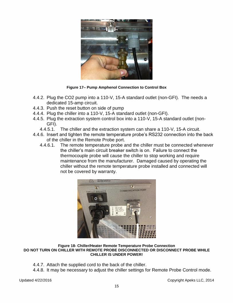
4.4.6. Insert and tighten the remote temperature probe’s RS232 connection into the back of the chiller in the Remote Probe port.
4.4.6.1. The remote temperature probe and the chiller must be connected whenever the chiller’s main circuit breaker switch is on. Failure to connect the thermocouple probe will cause the chiller to stop working and require maintenance from the manufacturer. Damaged caused by operating the chiller without the remote temperature probe installed and connected will not be covered by warranty.
Figure 18- Chiller/Heater Remote Temperature Probe Connection DO NOT TURN ON CHILLER WITH REMOTE PROBE DISCONNECTED OR DISCONNECT PROBE WHILE
CHILLER IS UNDER POWER!
4.4.7. Attach the supplied cord to the back of the chiller. 4.4.8. It may be necessary to adjust the chiller settings for Remote Probe Control mode.

Updated 4/22/2016 Copyright Apeks LLC, 2014
16
4.4.8.1. To verify chiller is in Remote Probe Control mode, press “Menu” button 5 times until the left display shows “P1” or “P2”
4.4.8.2. If left display shows “P1”, then chiller is in Remote Probe Control mode and no other adjustments are necessary. Press menu 1 time so the left display shows water pressure in “psi”.
4.4.8.3. NOTE: When “P1” is displayed on the left screen, the temperature of the water inside the chiller displayed on the right screen.
4.4.9. If left display shows “P2”, then press and hold menu button for ~3 seconds, press menu button 6 times until “rP” is displayed on the left, and use the temperature control knob to adjust the right display setting to “rPC”. Wait for 10 seconds for the chiller to reset out of the menu mode.
4.4.10. Coolant fluid (50/50 mix of distilled water and propylene glycol) is added to the system through the reservoir cap on the top of the chiller.
4.4.10.1. After the system is operational, recheck the coolant level (while the system is running) and add more coolant as necessary.
4.4.11. Watch this video for reference to chiller setup and operation; https://www.youtube.com/watch?v=8u9S-3sUCjs
More detailed operating instructions for the heater/chiller can be found in the
manufacturer’s operating instructions.
Updated 4/22/2016 Copyright Apeks LLC, 2014
17
5. System Operation The following operating instructions are for the 1500-1L system recirculating CO2 system. Instructions assume that chiller and CO2 pump are OEM supplied. Failure to follow the instructions provided below may void the warranty of the 1500-1L system.
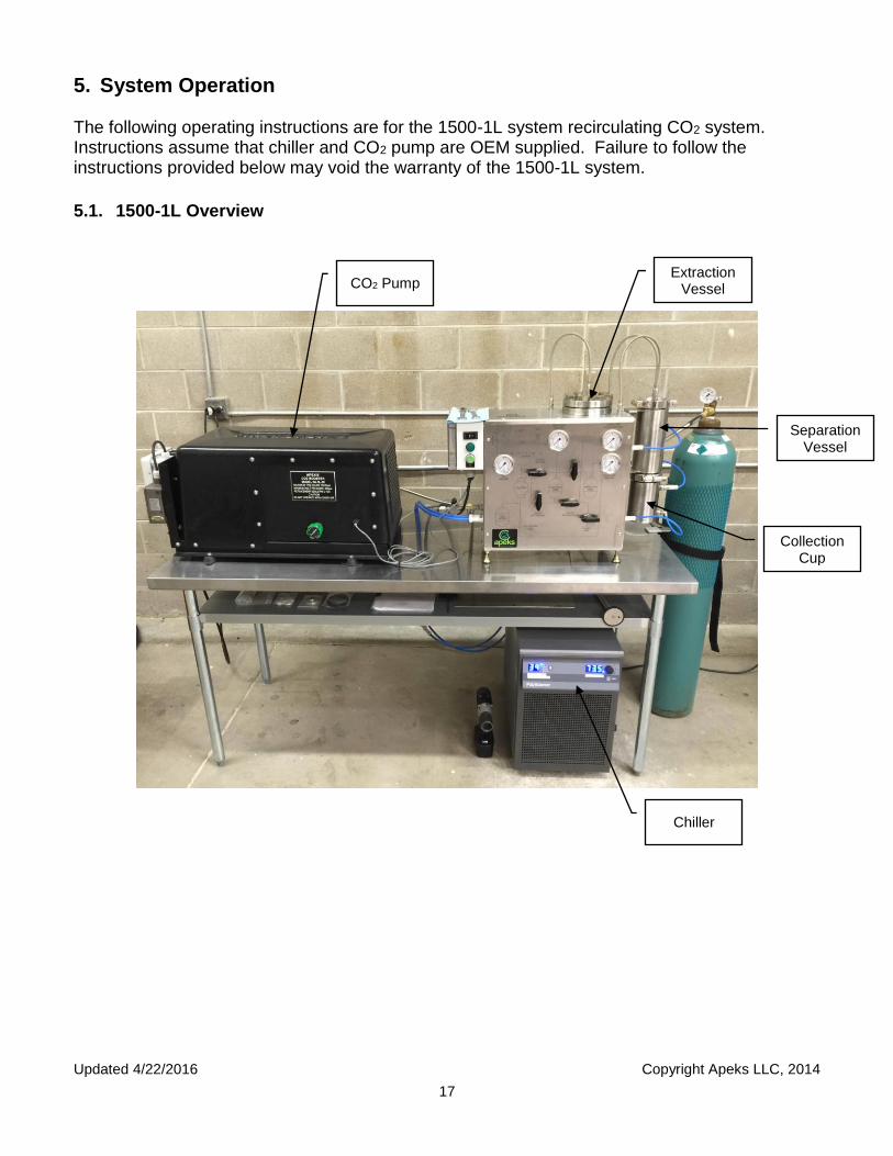
5.1. 1500-1L Overview
Chiller
CO2 Pump
Separation Vessel
Collection Cup
Extraction Vessel

Updated 4/22/2016 Copyright Apeks LLC, 2014
18
5.2. Pre-Cleaning 5.2.1. The 1500-1L system is constructed from 304 or 316 stainless steel and can be
cleaned with any cleaner that is compatible with both stainless steel and your extracted product. Simple Green cleaner or ethanol works well for most applications.
5.2.2. The system should be cleaned to the appropriate level prior to processing each batch of botanical material.
5.2.2.1. Apeks takes great care to clean all systems prior to shipping, but it is the user’s responsibility to ensure that the system meets their desired level of cleanliness.
5.3. Opening Extraction Vessel
WARNING DO NOT ATTEMPT TO OPEN A VESSEL UNDER PRESSURE! Always make sure a vent path for the vessel is opened and the corresponding pressure gauge(s) reads zero prior to loosening the vessel closure bolts.
5.3.1. This operation cannot be performed during an extraction. The extraction must be
stopped prior to opening the Extraction vessel 5.3.2. Open valves 1, 2, 3, 4, 5 and the separator vent assembly on the side of the
extraction system.
Figure 21. Required valve positions for opening extraction vessel
5.3.3. Remove the bolts on the top of the vessel using a 1-5/16” impact socket and
supplied impact wrench. 5.3.4. Lift the flange and set it on the top of the system. Use caution not to crimp or
otherwise damage the connecting hose. The connecting hose can be disconnected from the system if desired.
5.3.5. Use caution not to scratch or otherwise damage the O-ring sealing surfaces on the flanges. Placing a sheet of paper, cardboard, or cloth between the flange and the top of the system will help protect the O-ring sealing surface.

Updated 4/22/2016 Copyright Apeks LLC, 2014
19
5.4. Loading Botanical or Other Media 5.4.1. Prior to loading material, ensure that you vent the system according to chapter 5.8
pg. 21 5.4.2. Material to be extracted is loaded directly into the extraction vessel. The supplied
funnel can be used to help minimize spillage. 5.4.2.1. Typically, botanicals perform best in CO2 extractions when ground to a
particle size between 50 µin and roughly the consistency of coffee grounds. 5.4.2.2. Any amount of material can be loaded into the Extraction Vessel – it does
not have to be full in order to operate correctly 5.4.3. Gentle compression or packing can be used to increase the amount of material
loaded in the vessel, however heavy compaction should be avoided because it will cause channeling of CO2 during the extraction process.
5.5. Closing Extraction Vessel 5.5.1. Ensure all sealing surfaces are clean and free of debris 5.5.2. Check the O-ring for any visible damage or defects. Replace as necessary
5.5.2.1. The O-ring does not require any lubrication 5.5.3. Close the vessel flange and install each of the closure bolts hand tight 5.5.4. Using the supplied impact wrench and socket, tighten the bolts in a star pattern.
Use the supplied impact wrench with 1-2 second bursts to deliver approximately 50 ft-lbs of torque to each bolt. Heavy torqueing of the bolts is not required.
Figure 22. Torque sequence for extraction vessel
5.6. Chiller Start Up 5.6.1. Verify chiller’s cooling lines are connected to the extraction system. 5.6.2. Turn chiller on
5.6.2.1. Main power switch is located on the back of the chiller. 5.6.2.2. Operation power button is located below the knob on the front of the chiller.
5.6.3. Set the target temperature to 65°F by quickly depressing the control knob on the chiller and turning it to the appropriate temperature.
5.6.3.1. In the event that the chiller is displaying temperatures in Celsius, turn off the main power switch, press and hold the menu button on the front of the
1
2
3
7
5
8
4
6
Updated 4/22/2016 Copyright Apeks LLC, 2014
20
machine and turn on the main power. Then let off the menu button. The chiller will briefly display dF indicating it is set to display Fahrenheit.
5.7. Conducting an Extraction 5.7.1. Verify the chiller is on and target temperature is set to 65°F. 5.7.2. Verify that a 50-lb cylinder of CO2 with more than 600-psi is connected to the
system. 5.7.3. Verify that material is loaded into extraction vessel and extraction vessel is
properly closed 5.7.3.1. The system can be run with no material in the extraction vessel. This can
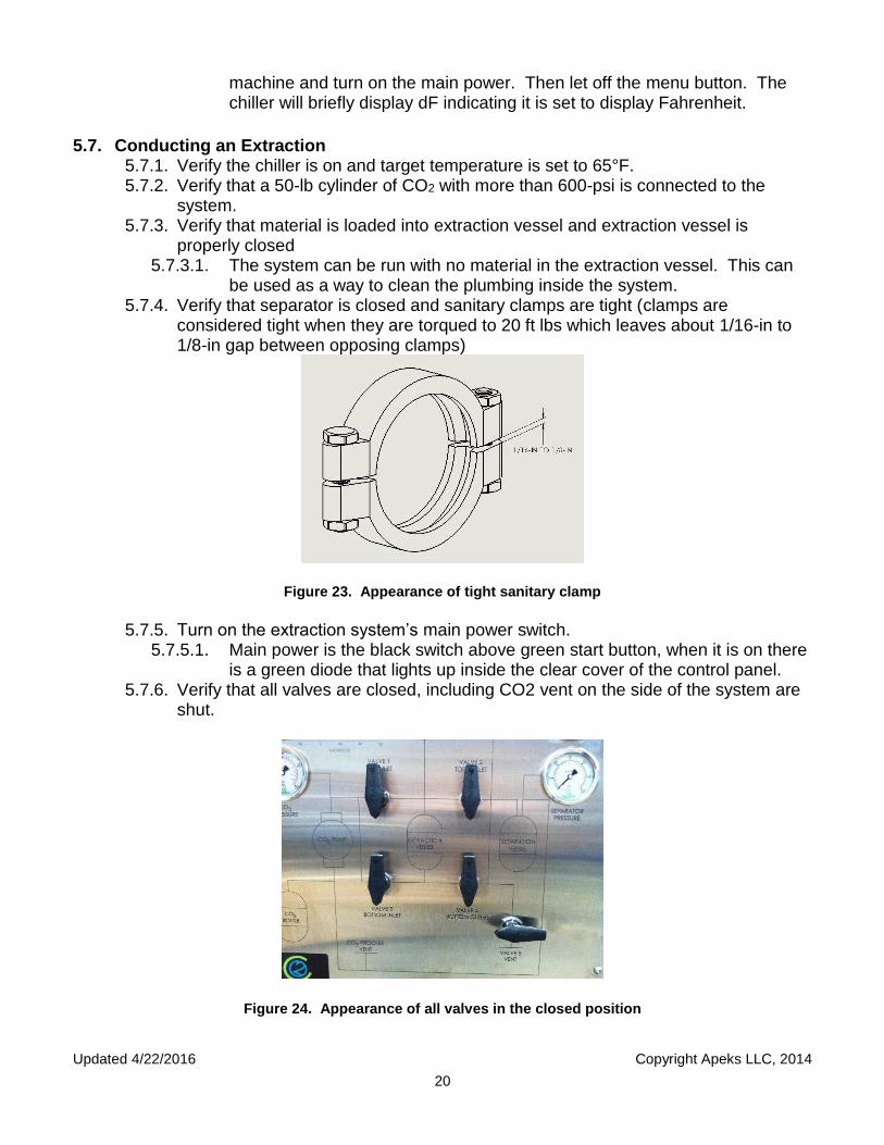
be used as a way to clean the plumbing inside the system. 5.7.4. Verify that separator is closed and sanitary clamps are tight (clamps are
considered tight when they are torqued to 20 ft lbs which leaves about 1/16-in to 1/8-in gap between opposing clamps)
Figure 23. Appearance of tight sanitary clamp
5.7.5. Turn on the extraction system’s main power switch.
5.7.5.1. Main power is the black switch above green start button, when it is on there is a green diode that lights up inside the clear cover of the control panel.
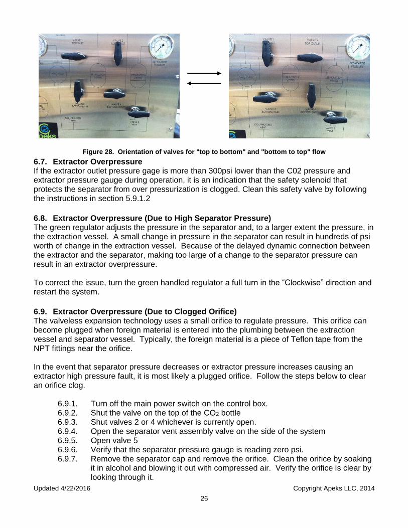
5.7.6. Verify that all valves are closed, including CO2 vent on the side of the system are shut.
Figure 24. Appearance of all valves in the closed position

Updated 4/22/2016 Copyright Apeks LLC, 2014
21
5.7.7. Open valves 1 and 4 for top to bottom flow or valves 2 and 3 for bottom to top flow. 5.7.7.1. It is recommended that flow be rotated between “top to bottom” and “bottom
to top” for each consecutive run.
Figure 25. Orientation of valves for "top to bottom" and "bottom to top" flow
5.7.8. Turn green regulator on the front of the CO2 Pump in clockwise or “increase”
direction approximately 3 to 4 full turns from all the way open. 5.7.8.1. After the first run, the green regulator should rarely need to be adjusted.
Adjusting it during a run or during startup will negatively impact the consistency of the resultant extract.
5.7.9. Open main valve on the top of the CO2 cylinder. Check pressure gauges on the 1L, all extractor and separator gauges should read zero if your system was depressurized to start with. If any extractor or separator gauge gains pressure after opening the CO2 cylinder it is an indication that one of the solenoids in the pump has failed, a solenoid is not in the correct orientation, or one of the pump seals has failed.
5.7.10. Start the extraction process by pressing and holding the “START” button for 3 seconds.
5.7.11. After system has been running for approximately 10-seconds, the separator should reach 400 psi (+/- 20psi) If target PSI has not been reached, adjust the green regulator clockwise (increase) to set separator pressure at ~400-psi. Make small adjustments and wait approximately 1-minute between adjustments for the system to stabilize.
5.7.11.1. If a separator pressure of 300psi is not reaches within 15 seconds the system will go into recovery mode.
5.7.11.2. The regulator should not need adjusted after initial setup unless the separator pressure has moved from its set point. Should this happen, adjust the regulator in the increasing or decreasing direction to create a corresponding pressure change in the separator.
5.7.11.3. The extractor should reach 800psi within 30 seconds. If not, check these items in order
5.7.11.3.1. Check CO2 cylinder pressure, if lower than 500psi turn bottle valve counter clockwise and look for an increase pressure.

Updated 4/22/2016 Copyright Apeks LLC, 2014
22
5.7.11.3.2. An increase in pressure above 500psi indicates that the valve was not fully open and should likewise result in an increase in extractor pressure.
5.7.11.3.3. If there is no increase in pressure this indicates that there is not enough CO2 in the bottle to pressurize the system. Put the system into recovery mode and start a new run with a full bottle.
5.7.11.4. Check separator pressure and adjusts green regulator if below 400psi 5.7.11.5. After checking both CO2 cylinder and separator pressure, you should
suspect that your pump seals are worn out and will need to perform a pump rebuild.
5.7.12. The system typically reaches a separator pressure of 420psi and an extractor pressure of 1200psi +/- 100psi within 15 minutes.
5.7.13. While the system is pressurizing, it is good practice to check for leaks. Leak can be detected by:
5.7.13.1. Sound: You will hear a hissing sound 5.7.13.2. Sight: Dry ice will form around connections that are leaking CO2 5.7.13.3. Touch: If you suspect a leak put your hand over the connection and you
will feel cold CO2 flowing out. 5.7.13.4. Tighten connections only enough to stop the leak of CO2. Do NOT over
tighten compression fittings. 5.7.14. After system is equalized (typically after 30 minutes) the separator
pressure should be 420psi. 5.7.14.1. If lower than 420psi, turn green valve clockwise or in the “increase”
direction in small incriminates (less than 1/8 of a turn) and wait one minute to see resultant pressure.
5.7.14.2. If higher than 420psi, turn green valve counter clockwise or in the “decrease” direction in a small incriminate. You must relieve pressure in separator using valve 6 on the side of the system (relieve pressure to 400psi) and then wait one minute to see resultant pressure. Repeat if necessary.
5.7.15. The extraction system defaults to a 4-hour run time. After the pump engages, each time the start button is momentarily depressed, the system will cycle to the next sequential run time (1, 4, 6 and 8 hours respectively).
5.7.16. After the system reaches its set extraction time it will automatically go into shut down/recovery mode.
5.7.17. Shut down and recovery are complete when the green run light on the front of the machine turns off
5.7.18. Leave the extraction system main power switch to the on position, ensuring that all pressure and temperature safety sensors are still being monitored by the controller.
5.8. Venting the System Prior to Opening 5.8.1. Slowly open both vents (Valve 5 and the separator vent assembly). The
amount of CO2 vented during this process is typically less than ½-lb. 5.8.2. Close the CO2 cylinder and press and hold the start button for 3 seconds. This
will allow the CO2 inside the pump to vent, thus extending pump seal life. 5.8.2.1. If the system is going to be immediately restarted, the previous step can be
skipped

Updated 4/22/2016 Copyright Apeks LLC, 2014
23
5.8.3. Opening all valves on the system will ensure that no CO2 is isolated or trapped between two valves.
5.8.4. Once all the gauges on the system’s front panel show zero pressure, the extractor and separator vessels can be opened for spent material removal and oil collection.
5.8.4.1. Increasing the temperature on the chiller can aid the oil collection process by increasing the temperature of the collected oil thus reducing its viscosity.
5.9. Cleaning Between Runs 5.9.1. After each run, the separator, inlet line, outlet line and entire inside of the
separator must be cleaned to remove residual oil and prevent it being carrying into the pump by the CO2.
5.9.1.1. Use the round squeegee and alcohol to clean the inside of the separator.
Figure 26. Separator inlet line and orientation of valves for inlet line cleaning
5.9.1.2. Disconnect the separator inlet line from the separator cap. Close valves 2
and 4, open valve 5. Close the valve on the CO2 bottle and turn on the main power switch. Add alcohol to the separator inlet line. Press and hold the start button for 3 seconds, then use compressed air to blow out the separator inlet line. The solvent will come out under the system, below valve 5.
Figure 27. Separator outlet line and pump inlet lines

Updated 4/22/2016 Copyright Apeks LLC, 2014
24
5.9.1.3. Disconnect the separator outlet line from the separator cap and disconnect the pump inlet line at the pump. Add alcohol into the separator outlet line until the solvent is colorless coming out the end that was connected to the pump inlet connection at the coalescing filter. Use compressed air to blow out the line ensuring that no residual alcohol remains in the line between the separator and the pump or the coalescing filter.
5.9.1.4. Reconnect the separator outlet line and pump inlet line.
WARNING Leave all valves open when not running the system to allow any residual pressure in the system caused by temperature fluctuations to vent.
5.10. What to Expect During an Extraction Once the start button has been pushed, the system will begin filling the extraction and separation vessels rapidly to approximately 300 to 500-psi. After the separator reaches 300psi the CO2 pump will turn on and the system will continue building pressure until reaching its operating pressure. Reaching operating pressure typically takes no more than 15-minutes. The extraction vessel pressure and separator pressure are dynamically linked because the system is closed loop. Increasing the separator pressure (via the green regulator) causes an increase in the extractor pressure. Note that there is a 4 to 6 minutes lag between the two vessels. If too many adjustments are made too quickly, the system will likely over pressure causing it to revert to shut down mode and begin putting the CO2 back into the CO2 cylinder. After the allotted run time has passed, the system will automatically go into Shut Down/Recovery mode. During shut down/recovery mode, the system takes the CO2 out of the extractor and separator vessels and pumps it back into the CO2 bottle. When CO2 recovery is complete, the green run light on the front of the system will turn off. At this point, there is a minimal amount of CO2 left in the separator and extractor vessels. The small amount of remaining CO2 is vented to atmosphere.
6. Troubleshooting 6.1. Ice On Separator It is normal for the clamps and flexible metal lines on the top of the separator to form ice during operation. If ice is forming on the outside of the separator vessels, that is an indicator that either the coolant lines were not connected properly or the chiller is turned off. If ice forms on the outside of the separator vessels, it suggests that the coolant cannot keep up and may be freezing inside the cooling jacket. In either event, the system should be shut down by pressing and holding the START button for 3 seconds. This will put the system into shut down/recovery mode so that the cooling system can be inspected. Do not attempt to work on the cooling system while the system is running.
6.2. Pump does not turn on 6.2.1. Verify you have power to pump 6.2.2. Check to make sure breaker in building is not tripped

Updated 4/22/2016 Copyright Apeks LLC, 2014
25
6.2.3. Push the reset button on the pump
6.3. Low Extractor Pressure (Due to Low Separator Pressure) If the extractor pressure is below 1200-psi, first verify that the CO2 cylinder has more than 500-psi in it. If yes, check the separator pressure. If the separator pressure is below 420-psi, adjust the green regulator in the clockwise or “increase” direction. This will increase the separator and the extractor pressure. Remember there is a 4 to 6 minutes delay between a change in the separator and a corresponding change to the extractor pressure.
6.4. Low Extractor Pressure (Due to Low Bottle Pressure) If the extractor pressure is below 1200-psi, first verify that the CO2 cylinder has more than 500-psi in it. If the bottle is low, you can swap it out without removing all the CO2 from your current run.
6.4.1. Turn off the main power switch on the control box. 6.4.2. Shut the valve on the top of the CO2 bottle 6.4.3. Shut valves 1, 2, 3 and 4. 6.4.4. Swap out the CO2 cylinders 6.4.5. Open valve 1 or 3, whichever was previously opened. 6.4.6. Close the valve on the separator vent assembly. 6.4.7. Open the valve on the CO2 cylinder. 6.4.8. Turn on the main power switch and press and hold the START button 6.4.9. After the pump engages open valve 2 or 4, whichever was previously opened. 6.4.10. Warning: Using a full bottle with a partially full system may result in over
pressurizing the pump when automatic recovery is initiated. Recommended procedure is to recover CO2 to low bottle and start a new run with full bottle.
6.5. Low Extractor Pressure (Due to Worn Pump Seals) If the extractor pressure is below 1200-psi, first verify that the CO2 cylinder has more than 500-psi in it. If yes, check the separator pressure. If the separator pressure is below 450-psi, adjust the green regulator in the increasing direction. If not, this is an indicator that the pump seals have likely reached the end of their life. Press and hold the START button for 3 seconds to put the system into shut down/recovery mode. Once the system shuts off, close the CO2 cylinder valve, open all the system valves and vent all the CO2 in the vessels. Use the instructions provided in Appendix C. to rebuild the CO2 pump.
6.6. Non-Uniform Extractor Pressure Gauges (Due to Clogged Extractor Filter) It may be necessary to reverse the flow in the Extraction Vessel during operation to either back flush a clogged extractor vessel filter, to prevent channeling through the finely ground dense media, or both. If more than a 300-psi pressure difference exists between the Extractor Pressure and either the CO2 Pressure or the Extractor Outlet Pressure, the extraction vessel filters may need to be back flushed. This is accomplished through an in-process flow reversal and does not require that the system be shut down. To reverse flow through the extractor, change the valves to match the images below. Note that it is better to open the currently closed valves before closing the open valves.
Updated 4/22/2016 Copyright Apeks LLC, 2014
26
Figure 28. Orientation of valves for "top to bottom" and "bottom to top" flow
6.7. Extractor Overpressure If the extractor outlet pressure gage is more than 300psi lower than the C02 pressure and extractor pressure gauge during operation, it is an indication that the safety solenoid that protects the separator from over pressurization is clogged. Clean this safety valve by following the instructions in section 5.9.1.2
6.8. Extractor Overpressure (Due to High Separator Pressure) The green regulator adjusts the pressure in the separator and, to a larger extent the pressure, in the extraction vessel. A small change in pressure in the separator can result in hundreds of psi worth of change in the extraction vessel. Because of the delayed dynamic connection between the extractor and the separator, making too large of a change to the separator pressure can result in an extractor overpressure. To correct the issue, turn the green handled regulator a full turn in the “Clockwise” direction and restart the system.
6.9. Extractor Overpressure (Due to Clogged Orifice) The valveless expansion technology uses a small orifice to regulate pressure. This orifice can become plugged when foreign material is entered into the plumbing between the extraction vessel and separator vessel. Typically, the foreign material is a piece of Teflon tape from the NPT fittings near the orifice. In the event that separator pressure decreases or extractor pressure increases causing an extractor high pressure fault, it is most likely a plugged orifice. Follow the steps below to clear an orifice clog.
6.9.1. Turn off the main power switch on the control box. 6.9.2. Shut the valve on the top of the CO2 bottle 6.9.3. Shut valves 2 or 4 whichever is currently open. 6.9.4. Open the separator vent assembly valve on the side of the system 6.9.5. Open valve 5 6.9.6. Verify that the separator pressure gauge is reading zero psi. 6.9.7. Remove the separator cap and remove the orifice. Clean the orifice by soaking
it in alcohol and blowing it out with compressed air. Verify the orifice is clear by looking through it.

Updated 4/22/2016 Copyright Apeks LLC, 2014
27
6.9.8. Reassemble the orifice using Teflon tape. Use caution to prevent excess Teflon tape from getting into the orifice. Tighten the orifice assembly such that the orifice is between tangent and +30 degrees from tangent to the separator wall as shown below. This facilitates cyclonic separation and minimizes oil carryover.
Figure 29. Orifice orientation A) 30-Deg off tangent and B) tangent
6.9.9. Replace the separator cap and gasket and tighten the clamp bolts. 6.9.10. Close the valve on the separator vent assembly. 6.9.11. Open valve 2 or 4 (whichever was previously open) 6.9.12. Open the valve on the CO2 cylinder 6.9.13. Turn on the main power switch and press and hold the START button for 3
seconds
6.10. Separator Overpressure (Due to Clogged Coalescing Filter) Higher than normal Separator pressure (>450psi) with a corresponding normal Extractor pressure (1200psi) is an indication that the coalescing filter is clogged. Replace the filter per Section 7.1.
6.11. Reset Button Anytime the pump loses power the reset button must be pushed to reset system. Also anytime the system over pressurizes and the pump shuts off, the reset button will need to be pushed.
Figure 30. Reset Button
A B

Updated 4/22/2016 Copyright Apeks LLC, 2014
28
6.12. Electrical Troubleshooting 6.12.1. Electrical troubleshooting on the system and gas booster will require a
voltmeter in AC/Volts mode. 6.12.2. Remove clear plastic case from HMI housing assembly. Use Phillip’s head
screw driver to depress and ¼ turn screws allowing screws to spring forward.
Figure 31. Control Panel Figure 32. Control Panel Screws
6.12.3. Procedures for checking voltage and corresponding reading are as follows: 6.12.3.1. T3/N w/ Pump On – 110-120V 6.12.3.2. T3/N w/ Pump Off – 0V 6.12.3.3. T3/L1 w/ Pump On – 0V 6.12.3.4. T3/L1 w/ Pump Off – 110-120V 6.12.3.5. A1/A2 w/ Pump On – 115-120V 6.12.3.6. A1/A2 w/ Pump Off – 0V
Figure 33. Location of N and L1 Figure 34. Location of T3 Figure 35. Location of A1 and A2
N L1 T3 A1 A2

Updated 4/22/2016 Copyright Apeks LLC, 2014
29
7. System Maintenance Maintenance on the system is critical to proper operation. Failure to follow these maintenance items can cause premature system failure and void the warranty. The maintenance items below pertain to the CO2 system only. Follow the manufacturer’s recommended maintenance plan for the chiller/heater unit. We include a small squeeze bottle to help with proper maintenance and cleaning of your systems C02 lines. We recommend alcohol or to clean the lines. Please label the bottle accordingly.
Figure 36. Front and back of chemical squeeze bottle
This maintenance schedule is based on the run timer on the CO2 pump control box.
Frequency Maintenance Item
After Each Extraction
Remove spent material from the extraction vessel by vacuuming it out through the top flange.
Verify the extractor filters are clear and free of debris
Check extraction vessel O-rings and O-rings groove sealing surfaces for damage – replace if necessary
Remove extracted oil from separator vessels and clean entire vessel and cup with alcohol.
Disconnect the separator inlet line from the separator. Close valves 2 and 4, open valve 5. Add alcohol to the separator inlet line. Close the valve on the CO2 bottle and turn on the main power switch. Press and hold the start button for 3 seconds, then use compressed air to blow out the separator inlet line. The solvent will come out under the system, below valve 5.
Disconnect the separator outlet line from the separator cap and disconnect the pump inlet line at the coalescing filter. Pour alcohol into the separator outlet line until the solvent is colorless coming out the end that was connected to the coalescing filter. Then use compressed air to blow out the line ensuring that no residual alcohol remains in the line between the separator and the pump.
Check separator vessel gaskets for damage – replace if necessary
Updated 4/22/2016 Copyright Apeks LLC, 2014
30
Clean inside of orifice tube with alcohol and bore brush to remove all white flaky resin and residual Teflon tape to include threads. Prior to reassembling orifice, ensure orifice is spotless and re-Teflon. Alcohol should stream out of orifice when poured into tube.
Frequency Maintenance Item
Every 20 Hours
Clean CO2 flow lines between pump, system and CO2 cylinder with alcohol and compressed air. Flow lines must be disconnected from pump and extraction system to thoroughly clean.
Check chiller/heater water level is between min and max
50-80 Hours
Inspect and Replace coalescing filter cartridge.
Replace both seals on the CO2 Pump and clean coalescing filter
When o Extractor can no longer achieve 1200psi o Pump starts making loud noises and/or sounds like its leaking o The pump is not able to get pressure below 220psi during C02
recovery
100 Hours Check the belt tension on the pump
Yearly
Schedule yearly maintenance with an Apeks Service Engineer to come onsite and perform a yearly inspection on the system. Please notify the Apeks service department one month in advance, and notify the service engineer of any issues prior to the visit. To schedule, call 844-446-4262 ext. 3
Resource Apeks online store (Serena Joseph 1-844-446-4262 ext. 4)
http://www.apekssupercritical.com/online-store/
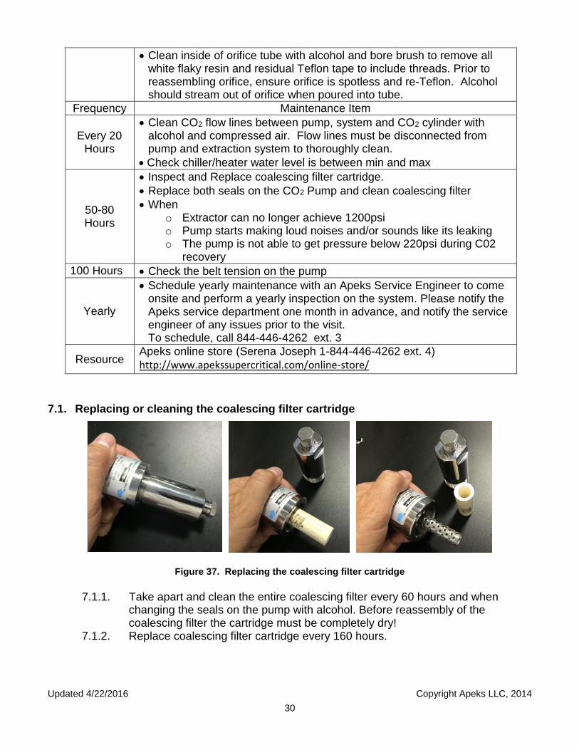
7.1. Replacing or cleaning the coalescing filter cartridge
Figure 37. Replacing the coalescing filter cartridge
7.1.1. Take apart and clean the entire coalescing filter every 60 hours and when
changing the seals on the pump with alcohol. Before reassembly of the coalescing filter the cartridge must be completely dry!
7.1.2. Replace coalescing filter cartridge every 160 hours.
B

Updated 4/22/2016 Copyright Apeks LLC, 2014
31
7.2. Check belt tension
7.2.1. Measure the length of span from sheave tangent points. Should be approximately 13 ¼ inches.
Figure 38. Tangent Points
7.2.2. Set the bottom of the large “O” ring at the correct point (13 ¼ inches)
13 ¼ Figure 39. Large O-ring set at length of tangent points
7.2.3. Set the top “O” ring down against the instruments flange.
Figure 40. Belt tension small O-ring at zero mark
7.2.4. Use a straight edge to establish a tangent point. See figure 36.
10
20
30
40
Updated 4/22/2016 Copyright Apeks LLC, 2014
32
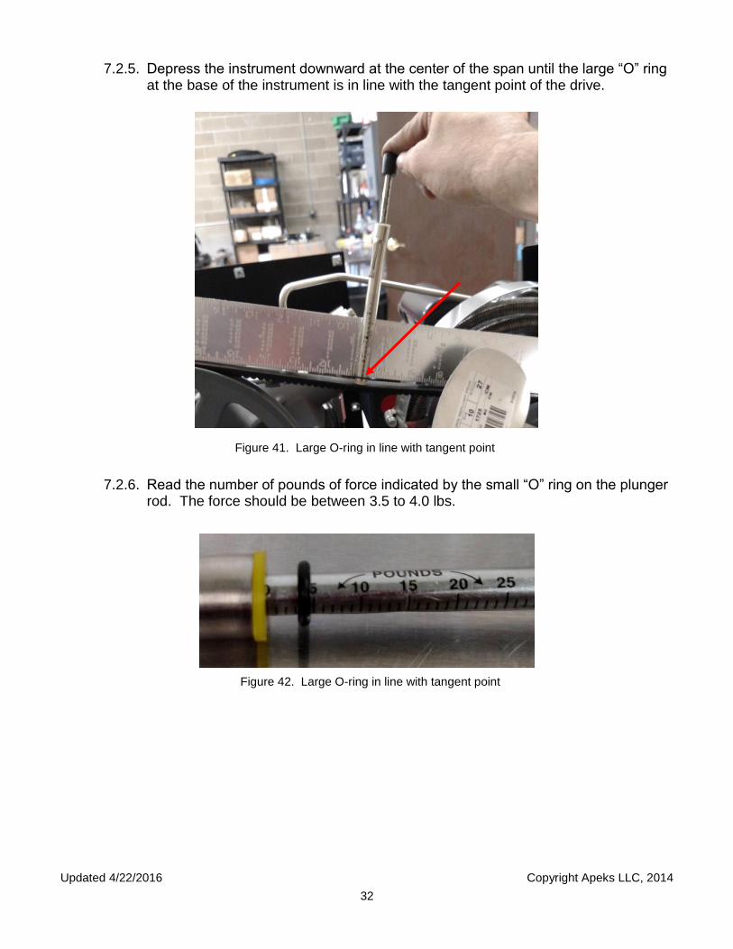
7.2.5. Depress the instrument downward at the center of the span until the large “O” ring at the base of the instrument is in line with the tangent point of the drive.
Figure 41. Large O-ring in line with tangent point
7.2.6. Read the number of pounds of force indicated by the small “O” ring on the plunger
rod. The force should be between 3.5 to 4.0 lbs. Figure 42. Large O-ring in line with tangent point

Updated 4/22/2016 Copyright Apeks LLC, 2014
33
Appendix A. 1500-1L Piping and Instrumentation Diagram

Updated 4/22/2016 Copyright Apeks LLC, 2014
34

Updated 4/22/2016 Copyright Apeks LLC, 2014
35
Appendix B. 1500-1L Electrical Control Diagram

Updated 4/22/2016 Copyright Apeks LLC, 2014
36

Updated 4/22/2016 Copyright Apeks LLC, 2014
37
Appendix C. CO2 Pump Rebuild Instructions

Updated 4/22/2016 Copyright Apeks LLC, 2014
38
Also, see instructional video; https://www.youtube.com/watch?v=tvhx1qcVUI0
M1. Disconnect power cord from electrical
source.
M2. Remove all booster cover screws
and cover.
M3. Disconnect inlet and outlet tubes from
each piston head.
M4. Remove the inlet check valve,
only remove one check valve at a time.
M5. Remove the spring from the head and
clean the valve, ball and spring. Replace when clean. Remove/clean the other inlet
check valve
M6. Remove the outlet check valves
(one at a time). Clean the valve, ball and spring. Replace when clean. Remove/clean the other outlet check valve.
INLET CHECK VAVLE OUTLET CHECK VALVE

Updated 4/22/2016 Copyright Apeks LLC, 2014
39
M7. Overhead view of check valves. Balls and springs must be orientated in this sequence
M7. Remove the 4 piston head bolts from
each head.
M8. Carefully slide, one at a time, each
piston head from piston.
M9. Slide brass guide plate off piston. Inspect
for wear. Replace if necessary. Clean all residual oil from piston and guide plate.
M10. Lay each cylinder head on bench
with piston seal facing up.
IN OUT

Updated 4/22/2016 Copyright Apeks LLC, 2014
40
M11. Remove piston seal from each piston
head with finger.
M12. Clean thoroughly with alcohol,
ensuring that all residual botanical oil is removed from the head and the piston.
M13. Use clean air to blow piston cavity clean.
M14. Place seal tool on cavity side of
piston head with “TOP” facing up.
M15. Start new seal, by hand, open side of seal
down, into tapered bore of tool plate.
M16. Place tool button on seal and push
seal through tool plate. The piston heads are now ready for installation. Reassemble carefully making sure that you install the heads correctly.
Updated 4/22/2016 Copyright Apeks LLC, 2014
41
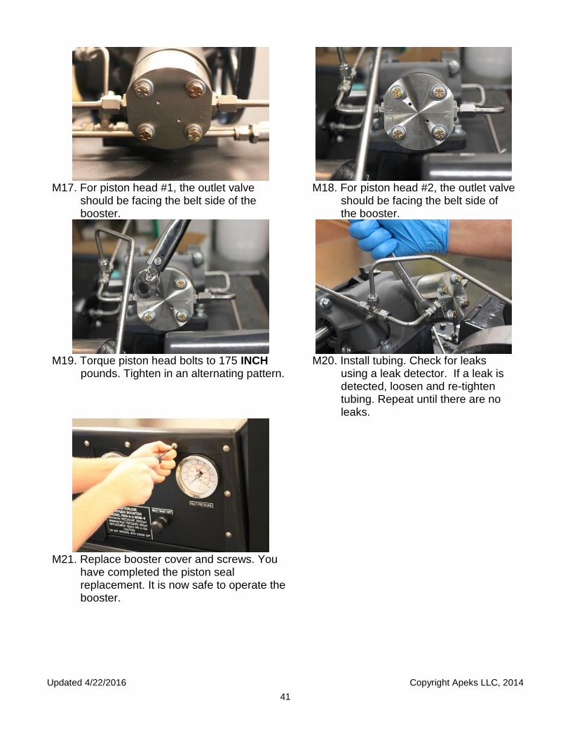
M17. For piston head #1, the outlet valve
should be facing the belt side of the booster.
M18. For piston head #2, the outlet valve
should be facing the belt side of the booster.
M19. Torque piston head bolts to 175 INCH
pounds. Tighten in an alternating pattern.
M20. Install tubing. Check for leaks
using a leak detector. If a leak is detected, loosen and re-tighten tubing. Repeat until there are no leaks.
M21. Replace booster cover and screws. You
have completed the piston seal replacement. It is now safe to operate the booster.

Updated 4/22/2016 Copyright Apeks LLC, 2014
42
Run #
External Variables Input Variables Output Variables
Start Time
Facility Temp
Facility Humidity
Botanical Designator
Botanical Weight
Orifice Size
Chiller Set
Point
Extractor Target
Pressure
Target Run Time
Extractor Temp
Separator Temp
Separator Pressure
Oil Weight
Water Weight

Updated 4/22/2016 Copyright Apeks LLC, 2014
43
Appendix D. Pre-Training Checklist

Updated 4/22/2016 Copyright Apeks LLC, 2014
44
In preparation of training,
Please refer to the manual for unpacking and setup instructions. Below is a check list of what needs to be
purchased or completed BEFORE scheduling your onsite training. Onsite training is a four hour block of
instruction that is NOT designed to include unpacking and set-up. Incomplete items at the time of onsite
training will result in incomplete training or additional charges for rescheduling.
o Must be complete before scheduling training: Print off complete Apeks manual and have on site
the day of training, along with the manual to the chiller.
o Must be complete before scheduling training: Apeks 1500-1L System is unpacked and setup in its
location of operation. Refer to unpacking instructions, Ch. 2-4, in the manual and videos below.
o Setup and Operation of 1500-1L
o Setup and Operation of Chiller for 1500-1L
o Must be complete before scheduling training: Insure you have 2 independent 110V, 15A, 60Hz, 1
phase NEMA 5-15 female outlets.
o 1 outlet dedicated to the systems controller and the chiller/heater
o 1 outlet dedicated to the pump
o Consult with an electrician. Do not put system/chiller/pump on GFI circuit.
o Must be complete before scheduling training: Purchase and have on site for training:
o 50lb bottle of CO2, gas feed, food grade or better
o Air compressor, air hose, and air blow gun; 1.6 gal. 1 HP Ultra Quiet Air Compressor
o 190 proof ethanol or higher for cleaning purposes
o Propylene glycol, 1 gal; Propylene Glycol
o Distilled water, 1 gal
o Crescent wrench with an opening greater than 1-1/4"
o Future maintenance will require:
o Shop Vacuum with a long, slim nozzle for removing material from extractor.
o Pencil Type Tension Tester; Gates Pencil Type Tension Tester, 30 lbs Deflection Force
o Proto J6064C Torque wrench; Proto® 3/8" Drive Torque Wrench 40-200 in-lbs
o Proto J5214HS socket; Proto J5214HS Socket, 3/8 In Dr, 7/16In, 6 Pt, Super Short
o CO2 Monitor; Amprobe CO2 100
o Material to be extracted must be very dry (food dehydrator) and grinded (blender) to the consistence
of coffee grounds. Have ready the day of training as a courtesy to your trainer.
An Apeks representative will contact you the following Monday to schedule onsite training.
Scheduling is typically 3 weeks out, please plan accordingly.
Updated 4/22/2016 Copyright Apeks LLC, 2014
45
References
YouTube Instructional Videos https://www.youtube.com/channel/UCzo7qXTIt01wfoKB2b9EO-g
Chiller set-up https://www.youtube.com/watch?v=tKzf9CtM9Uk
Cleaning Solenoids https://www.youtube.com/watch?v=6TC9VWXmfPk Replacing Seals https://www.youtube.com/watch?v=tvhx1qcVUI0 Set-up and operation of the 1L extractor https://www.youtube.com/watch?v=xypB-JOqHkY Orientation of orifice https://www.youtube.com/watch?v=t4Ev8veMMVY Apeks online store (Serena Joseph 1-844-446-4262 ext. 4)
http://www.apekssupercritical.com/online-store/