150-lb. drywall and panel hoist - northern tool · read & save these instructions 150-lb....
TRANSCRIPT

READ & SAVE THESE INSTRUCTIONS
150-Lb. Drywall and Panel Hoist
Owner’s Manual
WARNING: Read carefully and understand all ASSEMBLY AND OPERATION
INSTRUCTIONS before operating. Failure to follow the safety rules and other basic safety
precautions may result in serious personal injury.
Item #57475

Page 2 of 22
Thank you very much for choosing an Ironton™ product!
For future reference, please complete the owner’s record below:
Serial Number/Lot Date Code: ________________________________
Purchase Date: ____________________________________________
Save the receipt, warranty, and this manual. It is important that you read
the entire manual to become familiar with this product before you begin
using it.
This hoist is designed for certain applications only. Northern Tool and
Equipment is not responsible for issues arising from modification or
improper use of this product such as an application for which it was not
designed. We strongly recommend that this product not be modified
and/or used for any application other than that for which it was designed.
For technical questions, please call 1-800-222-5381.

Page 3 of 22
Table of Contents
Intended Use .......................................................................................................................................... 4
Technical Specifications ...................................................................................................................... 4
Important Safety Information ............................................................................................................... 4
Specific Operation Warnings ............................................................................................................... 6
Main Parts of Hoist ................................................................................................................................ 6
Assembly Instructions .......................................................................................................................... 6
Before Each Use .................................................................................................................................. 11
Operating Instructions ........................................................................................................................ 11
After Each Use ..................................................................................................................................... 16
Maintenance ........................................................................................................................................ 17
Troubleshooting .................................................................................................................................. 17
Parts Diagram ...................................................................................................................................... 18
Parts List .............................................................................................................................................. 19
Replacement Parts .............................................................................................................................. 20
Limited Warranty ................................................................................................................................. 21

Page 4 of 22
Intended Use
The Ironton 150-Lb Drywall and Panel Hoist allows one person to lift a drywall panel without
assistance. The panel can be raised to a maximum height of 11 feet for attachment to level ceilings-or
(with the lift's cradle tilted) to sloped ceilings or side walls. For higher ceilings, an extension accessory
is available that increases the lift to 16 feet. The hoist’s cradle can support up to 150 lb.
Technical Specifications
Property Specification
Load Capacity 150 lb.
Extension Bar (#57476 not included) Lifts Drywall up to 15’ Maximum
Lift 11’
Swivel Wheels 5 inch
Important Safety Information
⚠WARNING
Read and understand all instructions. Failure to follow all instructions may result in serious injury
or property damage.
The warnings, cautions, and instructions in this manual cannot cover all possible conditions or
situations that could occur. Exercise common sense and caution when using this tool. Always be
aware of the environment and ensure that the tool is used in a safe and responsible manner.
Do not allow persons to operate or assemble the product until they have read this manual and
have developed a thorough understanding of how it works.
Do not modify this product in any way. Unauthorized modification may impair the function and/or
safety and could affect the life of the product. There are specific applications for which the product
was designed.
Use the right tool for the job. DO NOT attempt to force small equipment to do the work of larger
industrial equipment. There are certain applications for which this equipment was designed. This
product will be safer and do a better job at the capacity for which it was intended. DO NOT use
this equipment for a purpose for which it was not intended.
Industrial or commercial applications must follow OSHA requirements.
⚠WARNING
WORK AREA SAFETY
Inspect the work area before each use. Keep work area clean, dry, free of clutter, and well-lit.
Cluttered, wet, or dark work areas can result in injury. Using the product in confined work areas
may put you dangerously close to cutting tools and rotating parts.
Do not use the product where there is a risk of causing a fire or an explosion; e.g., in the presence
of flammable liquids, gases, or dust. The product can create sparks, which may ignite the
flammable liquids, gases, or dust.
Do not allow the product to come into contact with an electrical source. The tool is not insulated

Page 5 of 22
and contact will cause electrical shock.
Keep children and bystanders away from the work area while operating the tool. Do not allow
children to handle the product.
Be aware of all power lines, electrical circuits, water pipes, and other mechanical hazards in your
work area. Some of these hazards may be hidden from your view and may cause personal injury
and/or property damage if contacted.
⚠WARNING
PERSONAL SAFETY
Stay alert, watch what you are doing, and use common sense when operating the tool. Do not use
the tool while you are tired or under the influence of drugs, alcohol, or medication. A moment of
inattention while operating the tool may result in serious personal injury.
Dress properly. Do not wear loose clothing, dangling objects, or jewelry. Keep your hair, clothing
and gloves away from moving parts. Loose clothes, jewelry, or long hair can be caught in moving
parts. Air vents on the tool often cover moving parts and should be avoided.
Wear the proper personal protective equipment when necessary. Use ANSI Z87.1 compliant safety
goggles (not safety glasses) with side shields, or when needed, a face shield. Use a dust mask in
dusty work conditions. Also use non-skid safety shoes, hardhat, gloves, dust collection systems,
and hearing protection when appropriate. This applies to all persons in the work area.
Do not overreach. Keep proper footing and balance at all times.
Remove keys or wrenches before connecting the tool to an air supply, power supply, or turning on
the tool. A wrench or key that is left attached to a rotating part of the tool may cause personal
injury.
Secure the work with clamps or a vise instead of your hand when practical. This safety precaution
allows for proper tool operation using both hands.
⚠CAUTION
HOIST USE AND CARE
Do not force the hoist. Products are safer and do a better job when used in the manner for which
they are designed. Plan your work, and use the correct product for the job.
Check for damaged parts before each use. Carefully check that the product will operate properly
and perform its intended function. Replace damaged or worn parts immediately. Never operate the
product with a damaged part.
Do not use a product with a malfunctioning switch. Any power tool that cannot be controlled with
the power switch is dangerous and must be repaired by an authorized service representative
before using.
Disconnect the power/air supply from the product and place the switch in the locked or off position
before making any adjustments, changing accessories, or storing the tool. Such preventive safety
measures reduce the risk of starting the tool accidentally.
Store the hoist when it is not in use. Store it in a dry, secure place out of the reach of children.

Page 6 of 22
Inspect the tool for good working condition prior to storage and before re-use.
Use only accessories that are recommended by the manufacturer for use with your product.
Accessories that may be suitable for one product may create a risk of injury when used with
another tool. Never use an accessory that has a lower operating speed or operating pressure than
the tool itself.
Keep guards in place and in working order. Never operate the product without the guards in place.
Do not leave the tool running unattended.
Specific Operation Warnings
⚠WARNING
To avoid injury, slide bar lock must be fully engaged if winch assembly is extended.
Wear ANSI Z87.1 compliant safety goggles, hard hat, heavy duty gloves, and steel toed boots
during setup and use.
Do not exceed the rated load capacity.
Do not use to transport people or pets.
Secure load before raising or lowering load.
Only use the hoist to raise and lower one panel at a time.
Never load a drywall panel or operate the hoist if the lock pins are not engaged at one of the three
positions.
Use ONLY for lifting a drywall panel.
To avoid serious injury, watch for overhead obstructions when raising panel.
Cradle drops rapidly when brake arm is released.
Control the winch with your right hand on wheel handle BEFORE releasing brake.
Be sure the winch components are clean and dry before operation.
Inspect the tool for wear or damage. Pay special attention to any wear or damage to the wire rope.
Carefully inspect the hoist before operating.
Main Parts of Hoist
Reference Subassembly
1 Tripod Base Assembly
2 Winch Assembly
3 Cradle Assembly
Assembly Instructions
⚠WARNING
Before continuing, be sure that the slide bar lock is fully engaged — that is, rotated clockwise as far as
possible

Page 7 of 22
Set up the Tripod Base (1):
Set the base on the floor, resting it on the casters (4).
Press down on the slide yoke (5) ring. Hold the ring down while you swing the two outer legs
(3) out until the yoke snaps back into place into the locking hole on the bottom of the slide
tube.
To prevent the tripod base (1) from rolling backward during assembly, lower the backstop tip
(7) as shown.
Set the frame assembly (9) onto the two "V" angles on the tripod base (1), and lower the
frame (9) about 1 inch until it is secured by the angles. Before continuing, be sure the frame
(9) is pushed all the way down and is held securely by the angles.

Page 8 of 22
Attach the handle (26) to the winch wheel (19). Tighten the nut, and then back it off slightly
so the handle (26) turns freely.

Page 9 of 22
Move the Winch Assembly into Working Position:
Hold the winch wheel (29) and brake arm (22). Rotate the winch wheel (29) forward slightly
while you lift the brake arm (22) to release the brake.
Raise the brake arm (22) all the way up. Grasp the winch post and grip the brake arm (22)
firmly with your thumb.
Place your right hand on top of the frame. Continue to grip the brake arm (22) as needed to
prevent cable backlash. Pull the winch assembly all the way toward you.

Page 10 of 22
When the winch is fully extended (away from the frame housing), release the brake arm (22)
and swing the retaining hook away (18) so it no longer secures the telescoping sections
inside the frame housing(9).
Press the winch assembly slightly back toward the frame. This automatically engages the
slide bar (14) lock to keep the winch fully extended.
Attach the cradle (28) to the frame.
Insert the cradle's (28) post into the opening on top of the frame.
Secure the cradle (28) to the frame by snapping the tilt latch upward so it hooks over the
stud on the cradle (28).
Attach the cross arms (48) to the cradle (28). Slide the tapered plates on the cross arms (48)
into the tapered sockets on the cradle (28).
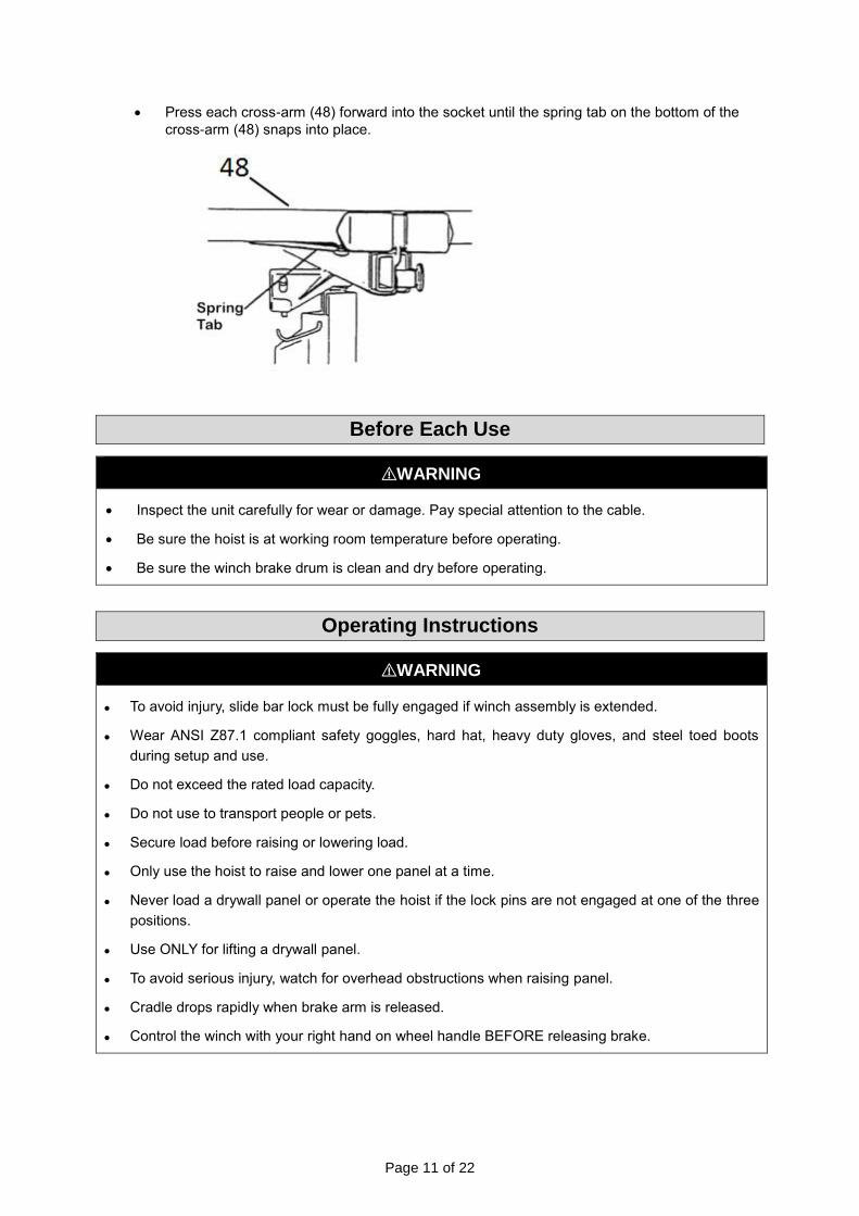
Page 11 of 22
Press each cross-arm (48) forward into the socket until the spring tab on the bottom of the
cross-arm (48) snaps into place.
Before Each Use
⚠WARNING
Inspect the unit carefully for wear or damage. Pay special attention to the cable.
Be sure the hoist is at working room temperature before operating.
Be sure the winch brake drum is clean and dry before operating.
Operating Instructions
⚠WARNING
To avoid injury, slide bar lock must be fully engaged if winch assembly is extended.
Wear ANSI Z87.1 compliant safety goggles, hard hat, heavy duty gloves, and steel toed boots
during setup and use.
Do not exceed the rated load capacity.
Do not use to transport people or pets.
Secure load before raising or lowering load.
Only use the hoist to raise and lower one panel at a time.
Never load a drywall panel or operate the hoist if the lock pins are not engaged at one of the three
positions.
Use ONLY for lifting a drywall panel.
To avoid serious injury, watch for overhead obstructions when raising panel.
Cradle drops rapidly when brake arm is released.
Control the winch with your right hand on wheel handle BEFORE releasing brake.

Page 12 of 22
Slide the Yoke Ring (5):
Press down on the slide yoke ring to unlatch the two forward legs so they can be rotated out to
the hoist’s working position or in to its storage position. A spring-loaded pin snaps into a hole on
the bottom of the slide tube to lock the folding legs into position.
Using the Backstop (7):
Pivot the backstop down to prevent the base from rolling backward, or up to allow the unit to
wheel freely.
Outriggers (29):
The outriggers on the cross arms (48) extend for supporting a longer drywall panel.
To extend an outrigger, pull out the lock pin with your right hand until you can slide the outrigger
out with your left hand.
Panel Support Hooks (49):
Open the support hook on each cross arm (48) to support the drywall panel when it is being
loaded, or when the cradle is tilted. To avoid damaging them, always close the support hooks
before transporting or storing the hoist.
Slide Bar Lock (15):
The slide bar lock holds the winch assembly at its operating (fully extended) position.

Page 13 of 22
Tilt Latch (33):
Allows the cradle to tilt (for loading a drywall panel or for raising the panel to a side wall or
sloped ceiling). To remove the cradle from the frame, pivot the tilt latch out and down. To lock
the cradle onto the frame without tilting, pivot the latch up to engage the stud on the cradle.
Brake Arm (22):
A spring-loaded brake holds the cradle at whatever height you raise it by cranking the winch
wheel. To lower the cradle, control the backward rotation of the winch by grasping the wheel
handle as you carefully raise the brake arm to release the brake.
Operating Procedures
To Load a Drywall Panel:
Set (lower) the backstop (7), so the hoist won't roll backward.
Swing open the panel support hooks on the two cross arms (48). Be sure the cradle is turned
so the support hooks are on the opposite side from the winch wheel.
Extend the cross arm outriggers (29) on the cradle as needed to fully support the length of
the drywall panel.
Release the tilt latch (33) to tilt the cradle (28).
Hold the drywall panel with its face paper toward the tilted cradle, and load the panel onto the
hoist as shown. Set the panel onto the support hooks, and carefully lean it against the cross
arms (48).
If installing the panel on a flat ceiling, tilt the cradle back up to its level position and lock the
tilt latch. If installing the panel on a side wall or a sloped ceiling, leave the cradle tilted.
Raise the backstop on the base, and carefully roll the hoist close to the position where the
panel will be installed.

Page 14 of 22
To Raise the Panel:
Crank the winch wheel (19) in the direction shown (hold the post for leverage) until the panel is at
the desired height. The brake (22) is spring-loaded to automatically hold the cradle at the selected
height when you stop cranking.
To Lower the Panel:
Grasp the wheel handle with your right hand so you can restrain the backward rotation of the
winch.
Retain your hold on the winch handle. Carefully release the brake with your left hand and
slowly rotate the wheel backward to lower the cradle to the desired height.
Extension Accessory--#57476 (sold separately)
To install the accessory and remove the Standard Telescoping Sections:
Release the cable tension until you can loosen the cable from the mooring tab in the winch. Pull
the cable out through the hole in the winch drum.
With large pliers, grasp the top end of the two telescoping sections and lift them out of the frame
housing as a unit. Pulling the free end of the cable toward the winch wheel will help raise the
telescoping sections.
Remove the telescoping sections (and the cable) completely out of the frame housing.
Page 15 of 22
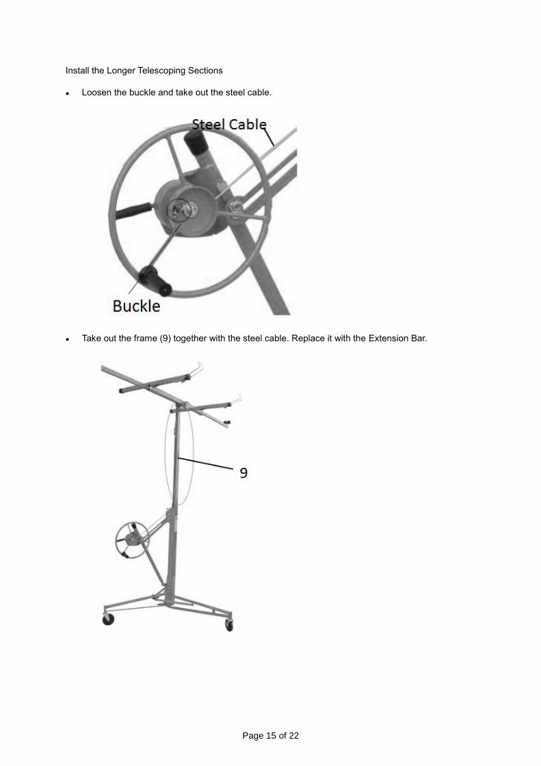
Install the Longer Telescoping Sections
Loosen the buckle and take out the steel cable.
Take out the frame (9) together with the steel cable. Replace it with the Extension Bar.

Page 16 of 22
Take the steel cable of the Extension bar through Part A and Part B (shown below). Attach it with
the buckle.
After Each Use
⚠WARNING
Always store the hoist in a dry, protected area.
Fold up the handle in the winch wheel.

Page 17 of 22
Maintenance
⚠WARNING
Do not lubricate any part of the winch components. The brake is friction-based and may fail if
lubricated.
Maintain the product by adopting a program of conscientious repair and maintenance in accordance with the following recommended procedures. It is recommended that the general condition of any tool be examined before it is used. Keep your tool in good repair Keep handles dry, clean, and free from oil and grease. The following chart is based on a normal operation schedule.
Maintenance Interval Maintenance Point
Before Use
Inspect the general condition of the tool. Check for loose
screws, wire rope fraying, other wire rope wear, misalignment
or binding of moving parts, cracked or broken parts, and any
other condition that may affect its safe operation
Inspect the tool before beginning work each day. Have the
wire rope replaced immediately as soon as wear is detected.
After Use
Occasionally oil the caster wheel bearings.
Occasionally use wax to the sides of the telescoping sections
as a lubricant.
Occasionally oil the cable pulleys. Crank up the telescoping
sections for access to the internal cable pulley. Never allow oil
or grease to contact the surface of the winch brake drum.
If the telescoping sections of the frame don't operate
smoothly, apply household paraffin to the sliding surfaces.
Troubleshooting
Use the table below to troubleshoot problems before contacting service personnel or your local
dealer. If the problem continues after troubleshooting, call your local dealer for assistance.
Failure Possible Cause Corrective Action
Casters don’t swivel smoothly.
Caster bearings are rusted. Oil the caster wheel bearings.
The telescoping sections do not slide freely.
Telescoping sections inside are rusted.
Apply paraffin wax or candlewax to the sides as a lubricant.

Page 18 of 22
Parts Diagram

Page 19 of 22
Parts List
Reference Part Description Quantity
1 Tripod Base Assembly 1
2 Center Leg (with Fasteners) 1
3 Out Leg (with Fasteners) 2
4 Caster 10cm 3
5 Slide Yoke Ring Tension Spring 1
6 Tie Arm (with Fasteners) 2
7 Rubber Backstop Tip 2
8 Frame Assembly 1
9 Frame Housing 1
10 Inner Telescoping Section 10cm 1
11 Out Telescoping Section with Pulley 11cm 1
12 Winch Assembly
13 Winch Host with Pin and Fastener 1
14 Slide Bar with Axle and Cotter Pin 1
15 Slide Bar Lock with Fasteners 1
16 Cable 411 cm 1
17 Cable Pulley with Axle and Cotter Pin 3
18 Retaining Hook 1
19 Winch Wheel with Flange Bearings 1
20 Bushing 2.22cm 1
21 M12*125 Bolt with Fasteners 1
22 Brake Arm Assembly 1
23 Brake Lining with Fasteners 1
24 Brake Arm Tension Spring 1
25 Brake Hub with Bolts 1
26 Winch Wheel Handle 1
27 Cradle Assembly
28 Cradle Body 1
29 Outrigger Lock Pin with Spring and Clip 2
30 Outrigger with End Caps 2
31 Cradle Mounting Lead Assembly 1
32 Mounting Head Body 1
33 Cradle Tilt Latch with Fasteners 1
34 Tension Spring 1
35 Compression Spring 2
36 Hinge Pin with Bolts 1
37 Title Pin 1
38 Mini Chain 1
39 Ring 1
40 Handle 1
41 Bolt M10*35 1
42 Flat mat 1
43 Nut M10 1
44 Bolt M10*35 1
45 Flat mat 1
46 Nut M10. 1
47 Pad 2
48 Cross-arm Body 2
49 Panel Support Lock with Fasteners 2
50 Cross-arm End Cap 2
51 Extension Accessory (not shown)
52 Inner Telescoping Section 1,800 cm (not shown) 1

Page 20 of 22
Reference Part Description Quantity
53 Outer Telescoping Section 1,800 cm (not shown) 1
54 Cable 520 cm (not shown) 1
Replacement Parts
For replacement parts and technical questions, please call Customer Service at 1-800-222-5381.
Not all product components are available for replacement. The illustrations provided are a
convenient reference to the location and position of parts in the assembly sequence.
When ordering parts, the following information will be required: item description, item model
number, item serial number/item lot date code, and the replacement part reference number.
The distributor reserves the rights to make design changes and improvements to product lines
and manuals without notice.

Page 21 of 22
Limited Warranty
Northern Tool and Equipment Company, Inc. ("We'' or ''Us'') warrants to the original purchaser only
(''You'' or ''Your'') that the Ironton product purchased will be free from material defects in both
materials and workmanship, normal wear and tear excepted, for a period of 90 days from date of
purchase. The foregoing warranty is valid only if the installation and use of the product is strictly in
accordance with product instructions. There are no other warranties, express or implied, including the
warranty of merchantability or fitness for a particular purpose. If the product does not comply with this
limited warranty, Your sole and exclusive remedy is that We will, at our sole option and within a
commercially reasonable time, either replace the product or product component without charge to You
or refund the purchase price (less shipping). This limited warranty is not transferable.
Limitations on the Warranty
This limited warranty does not cover: (a) normal wear and tear; (b) damage through abuse, neglect,
misuse, or as a result of any accident or in any other manner; (c) damage from misapplication,
overloading, or improper installation; (d) improper maintenance and repair; and (e) product alteration
in any manner by anyone other than Us, with the sole exception of alterations made pursuant to
product instructions and in a workmanlike manner.
Obligations of Purchaser
You must retain Your product purchase receipt to verify date of purchase and that You are the original
purchaser. To make a warranty claim, contact Us at 1-800-222-5381, identify the product by make
and model number, and follow the claim instructions that will be provided. The product and the
purchase receipt must be provided to Us in order to process Your warranty claim. Any returned
product that is replaced or refunded by Us becomes our property. You will be responsible for return
shipping costs or costs related to Your return visit to a retail store.
Remedy Limits
Product replacement or a refund of the purchase price is Your sole remedy under this limited warranty
or any other warranty related to the product. We shall not be liable for: service or labor charges or
damage to Your property incurred in removing or replacing the product; any damages, including,
without limitation, damages to tangible personal property or personal injury, related to Your improper
use, installation, or maintenance of the product or product component; or any indirect, incidental or
consequential damages of any kind for any reason.
Assumption of Risk
You acknowledge and agree that any use of the product for any purpose other than the specified
use(s) stated in the product instructions is at Your own risk.
Governing Law
This limited warranty gives You specific legal rights, and You also may have other rights which vary
from state to state. Some states do not allow limitations or exclusions on implied warranties or
incidental or consequential damages, so the above limitations may not apply to You. This limited
warranty is governed by the laws of the State of Minnesota, without regard to rules pertaining to
conflicts of law. The state courts located in Dakota County, Minnesota shall have exclusive jurisdiction
for any disputes relating to this warranty.

Page 22 of 22
Distributed by:
Northern Tool & Equipment Company, Inc.
Burnsville, Minnesota 55306
www.northerntool.com
Made in China