15 planer - mike's tools€¦ · instruction manual 15" planer (model 22-785) ... shown...
TRANSCRIPT

INS
TRU
CTIO
NM
AN
UA
L15" Planer(Model 22-785)
(Model 22-785X)
PART NO. 909593 - 06-07-05Copyright © 2005 Delta Machinery
To learn more about DELTA MACHINERY visit our website at: www.deltamachinery.com.
For Parts, Service, Warranty or other Assistance,
please call 1-800-223-7278 (In Canada call 1-800-463-3582).
Shown with Deltaaccessory planer stand
and roller extension tables

2
TABLE OF CONTENTS
Read and understand all warnings and operating instructions before using any tool or equipment. Whenusing tools or equipment, basic safety precautions should always be followed to reduce the risk of personal injury.Improper operation, maintenance or modification of tools or equipment could result in serious injury and propertydamage. There are certain applications for which tools and equipment are designed. Delta Machinery stronglyrecommends that this product NOT be modified and/or used for any application other than for which it was designed.
If you have any questions relative to its application DO NOT use the product until you have written Delta Machineryand we have advised you.
Online contact form at www.deltamachinery.com
Postal Mail: Technical Service ManagerDelta Machinery4825 Highway 45 NorthJackson, TN 38305(IN CANADA: 125 Mural St. Suite 300, Richmond Hill, ON, L4B 1M4)
Information regarding the safe and proper operation of this tool is available from the following sources:
Power Tool Institute1300 Sumner Avenue, Cleveland, OH 44115-2851www.powertoolinstitute.org
National Safety Council1121 Spring Lake Drive, Itasca, IL 60143-3201
American National Standards Institute, 25 West 43rd Street, 4 floor, New York, NY 10036 www.ansi.orgANSI 01.1Safety Requirements for Woodworking Machines, and
the U.S. Department of Labor regulations www.osha.gov
IMPORTANT SAFETY INSTRUCTIONS
SAVE THESE INSTRUCTIONS!
IMPORTANT SAFETY INSTRUCTIONS . . . . . . . . . . . . . . . . . . . . . . . . . . . . . . . . . . . . . . . . . . . . . . . . . . . . . . . . . . .2SAFETY GUIDELINES . . . . . . . . . . . . . . . . . . . . . . . . . . . . . . . . . . . . . . . . . . . . . . . . . . . . . . . . . . . . . . . . . . . . . . . .3GENERAL SAFETY RULES . . . . . . . . . . . . . . . . . . . . . . . . . . . . . . . . . . . . . . . . . . . . . . . . . . . . . . . . . . . . . . . . . . . .4ADDITIONAL SPECIFIC SAFETY RULES . . . . . . . . . . . . . . . . . . . . . . . . . . . . . . . . . . . . . . . . . . . . . . . . . . . . . . . . .5FUNCTIONAL DESCRIPTION . . . . . . . . . . . . . . . . . . . . . . . . . . . . . . . . . . . . . . . . . . . . . . . . . . . . . . . . . . . . . . . . . .7CARTON CONTENTS . . . . . . . . . . . . . . . . . . . . . . . . . . . . . . . . . . . . . . . . . . . . . . . . . . . . . . . . . . . . . . . . . . . . . . . . .7ASSEMBLY . . . . . . . . . . . . . . . . . . . . . . . . . . . . . . . . . . . . . . . . . . . . . . . . . . . . . . . . . . . . . . . . . . . . . . . . . . . . . . . . .8OPERATION . . . . . . . . . . . . . . . . . . . . . . . . . . . . . . . . . . . . . . . . . . . . . . . . . . . . . . . . . . . . . . . . . . . . . . . . . . . . . . .10TROUBLESHOOTING . . . . . . . . . . . . . . . . . . . . . . . . . . . . . . . . . . . . . . . . . . . . . . . . . . . . . . . . . . . . . . . . . . . . . . .18MAINTENANCE . . . . . . . . . . . . . . . . . . . . . . . . . . . . . . . . . . . . . . . . . . . . . . . . . . . . . . . . . . . . . . . . . . . . . . . . . . . . .18SERVICE . . . . . . . . . . . . . . . . . . . . . . . . . . . . . . . . . . . . . . . . . . . . . . . . . . . . . . . . . . . . . . . . . . . . . . . . . . . . . . . . . .19ACCESSORIES . . . . . . . . . . . . . . . . . . . . . . . . . . . . . . . . . . . . . . . . . . . . . . . . . . . . . . . . . . . . . . . . . . . . . . . . . . . .19WARRANTY . . . . . . . . . . . . . . . . . . . . . . . . . . . . . . . . . . . . . . . . . . . . . . . . . . . . . . . . . . . . . . . . . . . . . . . . . . . . . . . .19SERVICE CENTER LOCATIONS . . . . . . . . . . . . . . . . . . . . . . . . . . . . . . . . . . . . . . . . . . . . . . . . . . . . . . . .back cover

3
Indicates an imminently hazardous situation which, if not avoided, will result in death or serious injury.
Indicates a potentially hazardous situation which, if not avoided, could result in death or serious injury.
Indicates a potentially hazardous situation which, if not avoided, may result in minor or moderate injury.
Used without the safety alert symbol indicates potentially hazardous situation which, if not avoided, mayresult in property damage.
It is important for you to read and understand this manual. The information it contains relates to protectingYOUR SAFETY and PREVENTING PROBLEMS. The symbols below are used to help you recognize thisinformation.
SAFETY GUIDELINES - DEFINITIONS
SOME DUST CREATED BY POWER SANDING, SAWING, GRINDING, DRILLING, AND OTHERCONSTRUCTION ACTIVITIES contains chemicals known to cause cancer, birth defects or other reproductive harm.Some examples of these chemicals are:· lead from lead-based paints,· crystalline silica from bricks and cement and other masonry products, and· arsenic and chromium from chemically-treated lumber. Your risk from these exposures varies, depending on how often you do this type of work. To reduce your exposure tothese chemicals: work in a well ventilated area, and work with approved safety equipment, always wear NIOSH/OSHAapproved, properly fitting face mask or respirator when using such tools.
CALIFORNIA PROPOSITION 65

4
GENERAL SAFETY RULES
READ AND UNDERSTAND ALL WARNINGS AND OPERATING INSTRUCTIONS BEFOREUSING THIS EQUIPMENT. Failure to follow all instructions listed below, may result in electric shock,fire, and/or serious personal injury or property damage.
IMPORTANT SAFETY INSTRUCTIONS
1. FOR YOUR OWN SAFETY, READ THE INSTRUCTIONMANUAL BEFORE OPERATING THE MACHINE. Learningthe machine’s application, limitations, and specifichazards will greatly minimize the possibility of accidentsand injury.
2. WEAR EYE AND HEARING PROTECTION. ALWAYSUSE SAFETY GLASSES. Everyday eyeglasses are NOTsafety glasses. USE CERTIFIED SAFETY EQUIPMENT.Eye protection equipment should comply with ANSI Z87.1standards. Hearing equipment should comply with ANSIS3.19 standards.
3. WEAR PROPER APPAREL. Do not wear loose clothing,gloves, neckties, rings, bracelets, or other jewelry whichmay get caught in moving parts. Nonslip footwear isrecommended. Wear protective hair covering to containlong hair.
4. DO NOT USE THE MACHINE IN A DANGEROUSENVIRONMENT. The use of power tools in damp or wetlocations or in rain can cause shock or electrocution. Keepyour work area well-lit to prevent tripping or placing arms,hands, and fingers in danger.
5. MAINTAIN ALL TOOLS AND MACHINES IN PEAKCONDITION. Keep tools sharp and clean for best and safestperformance. Follow instructions for lubricating and changingaccessories. Poorly maintained tools and machines can furtherdamage the tool or machine and/or cause injury.
6. CHECK FOR DAMAGED PARTS. Before using the machine,check for any damaged parts. Check for alignment ofmoving parts, binding of moving parts, breakage of parts,and any other conditions that may affect its operation. Aguard or any other part that is damaged should beproperly repaired or replaced. Damaged parts can causefurther damage to the machine and/or injury.
7. KEEP THE WORK AREA CLEAN. Cluttered areas and benchesinvite accidents.
8. KEEP CHILDREN AND VISITORS AWAY. Your shop is apotentially dangerous environment. Children and visitors can beinjured.
9. REDUCE THE RISK OF UNINTENTIONAL STARTING. Makesure that the switch is in the “OFF” position beforeplugging in the power cord. In the event of a power failure,move the switch to the “OFF” position. An accidentalstart-up can cause injury.
10. USE THE GUARDS. Check to see that all guards are inplace, secured, and working correctly to reduce the risk ofinjury.
11. REMOVE ADJUSTING KEYS AND WRENCHESBEFORE STARTING THE MACHINE. Tools, scrap pieces,and other debris can be thrown at high speed, causinginjury.
12. USE THE RIGHT MACHINE. Don’t force a machine or anattachment to do a job for which it was not designed.Damage to the machine and/or injury may result.
13. USE RECOMMENDED ACCESSORIES. The use ofaccessories and attachments not recommended by Deltamay cause damage to the machine or injury to the user.
14. USE THE PROPER EXTENSION CORD. Make sure yourextension cord is in good condition. When using anextension cord, be sure to use one heavy enough to carrythe current your product will draw. An undersized cord willcause a drop in line voltage, resulting in loss of power andoverheating. See the Extension Cord Chart for the correctsize depending on the cord length and nameplate ampererating. If in doubt, use the next heavier gauge. The smallerthe gauge number, the heavier the cord.
15. SECURE THE WORKPIECE. Use clamps or a vise to holdthe workpiece when practical. Loss of control of aworkpiece can cause injury.
16. FEED THE WORKPIECE AGAINST THE DIRECTION OF THEROTATION OF THE BLADE, CUTTER, OR ABRASIVESURFACE. Feeding it from the other direction will causethe workpiece to be thrown out at high speed.
17. DON’T FORCE THE WORKPIECE ON THE MACHINE.Damage to the machine and/or injury may result.
18. DON’T OVERREACH. Loss of balance can make you fallinto a working machine, causing injury.
19. NEVER STAND ON THE MACHINE. Injury could occur if the tooltips, or if you accidentally contact the cutting tool.
20. NEVER LEAVE THE MACHINE RUNNING UNATTENDED.TURN THE POWER OFF. Don’t leave the machine until it comesto a complete stop. A child or visitor could be injured.
21. TURN THE MACHINE “OFF”, AND DISCONNECT THEMACHINE FROM THE POWER SOURCE before installing orremoving accessories, before adjusting or changing set-ups, or when making repairs. An accidental start-up cancause injury.
22. MAKE YOUR WORKSHOP CHILDPROOF WITHPADLOCKS, MASTER SWITCHES, OR BY REMOVINGSTARTER KEYS. The accidental start-up of a machine bya child or visitor could cause injury.
23. STAY ALERT, WATCH WHAT YOU ARE DOING, ANDUSE COMMON SENSE. DO NOT USE THE MACHINEWHEN YOU ARE TIRED OR UNDER THE INFLUENCEOF DRUGS, ALCOHOL, OR MEDICATION. A moment ofinattention while operating power tools may result in injury.
24. USE OF THIS TOOL CAN GENERATE ANDDISBURSE DUST OR OTHER AIRBORNE PARTICLES,INCLUDING WOOD DUST, CRYSTALLINE SILICA DUSTAND ASBESTOS DUST. Direct particles away from face andbody. Always operate tool in well ventilated area and providefor proper dust removal. Use dust collection system whereverpossible. Exposure to the dust may cause serious andpermanent respiratory or other injury, including silicosis (aserious lung disease), cancer, and death. Avoid breathing thedust, and avoid prolonged contact with dust. Allowing dust toget into your mouth or eyes, or lay on your skin may promoteabsorption of harmful material. Always use properly fittingNIOSH/OSHA approved respiratory protection appropriate forthe dust exposure, and wash exposed areas with soap andwater.

5
FAILURE TO FOLLOW THESE RULES MAY RESULT IN SERIOUS PERSONAL INJURY.
ADDITIONAL SPECIFIC SAFETY RULES
SAVE THESE INSTRUCTIONS. Refer to them often and use them to instruct others.
1. DO NOT OPERATE THIS MACHINE until it iscompletely assembled and installed according tothe instructions. A machine incorrectly assembledcan cause serious injury.
2. OBTAIN ADVICE from your supervisor, instructor,or another qualified person if you are notthoroughly familiar with the operation of thismachine. Knowledge is safety.
3. FOLLOW ALL WIRING CODES and recommend-ed electrical connections to prevent shock orelectrocution.
4. KEEP KNIVES SHARP and free from rust andpitch. Dull or rusted knives work harder and cancause kickback.
5. NEVER TURN THE MACHINE “ON” before clearingthe table of all objects (tools, scraps of wood, etc.).Flying debris can cause serious injury.
6. NEVER TURN THE MACHINE “ON” with the work-piece contacting the cutterhead. Kickback canoccur.
7. SECURE THE MACHINE TO A SUPPORTING SUR-FACE to prevent the machine from sliding, walkingor tipping over.
8. PROPERLY SECURE THE KNIVES IN THE CUTTER-HEAD before turning the power “ON”. Looseblades may be thrown out at high speeds causingserious injury.
9. LOCK THE SPEED SETTING SECURELY beforefeeding the workpiece through the machine.Changing speeds while planing can cause kick-back.
10. AVOID AWKWARD OPERATIONS AND HAND POSI-TIONS. A sudden slip could cause a hand to moveinto the knives.
11. KEEP ARMS, HANDS, AND FINGERS away fromthe cutterhead, the chip exhaust opening, and thefeed rollers to prevent severe cuts.
12. NEVER REACH INTO THE CUTTERHEAD AREAwhile the machine is running. Your hands can bedrawn into the knives.
13. DO NOT STAND IN LINE OF THE WORKPIECE.Kickback can cause injury.
14. ALLOW THE CUTTERHEAD TO REACH FULL SPEEDbefore feeding a workpiece. Changing speedswhile planing can cause kickback.
15. WHEN PLANING BOWED STOCK, place the concave(cup down) side of the stock on the table and cutwith the grain to prevent kickback.
16. DO NOT FEED A WORKPIECE that is warped,contains knots, or is embedded with foreignobjects (nails, staples, etc.). Kickback can occur.
17. DO NOT FEED A SHORT, THIN, OR NARROWWORKPIECE INTO THE MACHINE. Your hands canbe drawn into the knives and/or the workpiece canbe thrown at high speeds. See the “OPERATION”section of this instruction manual for details.
18. DO NOT FEED A WORKPIECE into the outfeed end ofthe machine. The workpiece will be thrown out ofthe opposite side at high speeds.
19. REMOVE SHAVINGS ONLY with the power “OFF” toprevent serious injury.
20. PROPERLY SUPPORT LONG OR WIDE WORK-PIECES. Loss of control of the workpiece can causeserious injury.
21. NEVER PERFORM LAYOUT, ASSEMBLY or set-upwork on the table/work area when the machine isrunning. Serious injury will result.
22. TURN THE MACHINE “OFF”, DISCONNECT IT FROMTHE POWER SOURCE, and clean the table/workarea before leaving the machine. LOCK THESWITCH IN THE “OFF” POSITION to prevent un-authorized use. Someone else might accidentallystart the machine and cause injury to themselvesor others.
23. ADDITIONAL INFORMATION regarding the safeand proper operation of power tools (i.e. a safetyvideo) is available from the Power Tool Institute,1300 Sumner Avenue, Cleveland, OH 44115-2851(www.powertoolinstitute.com). Information is alsoavailable from the National Safety Council, 1121Spring Lake Drive, Itasca, IL 60143-3201. Pleaserefer to the American National Standards InstituteANSI 01.1 Safety Requirements for WoodworkingMachines and the U.S. Department of LaborRegulations.
6
Fig. A
GROUNDED OUTLET BOX
CURRENTCARRYING
PRONGS
GROUNDING BLADEIS LONGEST OF THE 3 BLADES
POWER CONNECTIONS
MOTOR SPECIFICATIONS
GROUNDING INSTRUCTIONS
3. Grounded, cord-connected machines intended foruse on a supply circuit having a nominal ratingbetween 150 - 250 volts, inclusive:
If the machine is intended for use on a circuit that has anoutlet that looks like the one illustrated in Fig. C, themachine will have a grounding plug that looks like theplug illustrated in Fig. C. Make sure the machine isconnected to an outlet having the same configuration asthe plug. No adapter is available or should be used withthis machine. If the machine must be re-connected foruse on a different type of electric circuit, the re-connection should be made by qualified servicepersonnel; and after re-connection, the machine shouldcomply with the National Electric Code and all local codesand ordinances.
Fig. C
GROUNDED OUTLET BOX
CURRENTCARRYING
PRONGS
GROUNDING BLADEIS LONGEST OF THE 3 BLADES
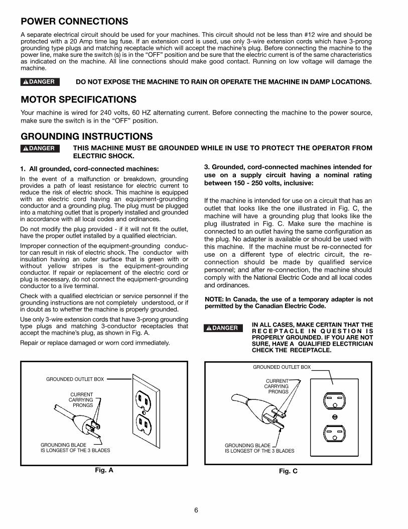
A separate electrical circuit should be used for your machines. This circuit should not be less than #12 wire and should beprotected with a 20 Amp time lag fuse. If an extension cord is used, use only 3-wire extension cords which have 3-pronggrounding type plugs and matching receptacle which will accept the machine’s plug. Before connecting the machine to thepower line, make sure the switch (s) is in the “OFF” position and be sure that the electric current is of the same characteristicsas indicated on the machine. All line connections should make good contact. Running on low voltage will damage themachine.
DO NOT EXPOSE THE MACHINE TO RAIN OR OPERATE THE MACHINE IN DAMP LOCATIONS.
Your machine is wired for 240 volts, 60 HZ alternating current. Before connecting the machine to the power source,make sure the switch is in the “OFF” position.
THIS MACHINE MUST BE GROUNDED WHILE IN USE TO PROTECT THE OPERATOR FROMELECTRIC SHOCK.
NOTE: In Canada, the use of a temporary adapter is notpermitted by the Canadian Electric Code.
IN ALL CASES, MAKE CERTAIN THAT THER E C E P T A C L E I N Q U E S T I O N I SPROPERLY GROUNDED. IF YOU ARE NOTSURE, HAVE A QUALIFIED ELECTRICIANCHECK THE RECEPTACLE.
1. All grounded, cord-connected machines:
In the event of a malfunction or breakdown, groundingprovides a path of least resistance for electric current toreduce the risk of electric shock. This machine is equippedwith an electric cord having an equipment-groundingconductor and a grounding plug. The plug must be pluggedinto a matching outlet that is properly installed and groundedin accordance with all local codes and ordinances.
Do not modify the plug provided - if it will not fit the outlet,have the proper outlet installed by a qualified electrician.
Improper connection of the equipment-grounding conduc-tor can result in risk of electric shock. The conductor withinsulation having an outer surface that is green with orwithout yellow stripes is the equipment-groundingconductor. If repair or replacement of the electric cord orplug is necessary, do not connect the equipment-groundingconductor to a live terminal.
Check with a qualified electrician or service personnel if thegrounding instructions are not completely understood, or ifin doubt as to whether the machine is properly grounded.
Use only 3-wire extension cords that have 3-prong groundingtype plugs and matching 3-conductor receptacles thataccept the machine’s plug, as shown in Fig. A.
Repair or replace damaged or worn cord immediately.

7
FOREWORD
Delta Models 22-785 and 22-785X are 15" (381mm) Planers with adjustable feed rate for optimum planing under load.They have the following cutting capacities; 15" (381mm) width, 6½" (165mm) thickness and 1/8" (5mm) depth of cut.
FUNCTIONAL DESCRIPTION
EXTENSION CORDSUse proper extension cords. Make sure
your extension cord is in good condition and is a 3-wireextension cord which has a 3-prong grounding typeplug and matching receptacle which will accept themachine’s plug. When using an extension cord, be sureto use one heavy enough to carry the current of themachine. An undersized cord will cause a drop in linevoltage, resulting in loss of power and overheating. Fig.D-1, shows the correct gauge to use depending on thecord length. If in doubt, use the next heavier gauge. Thesmaller the gauge number, the heavier the cord.
Fig. D-1
MINIMUM GAUGE EXTENSION CORDRECOMMENDED SIZES FOR USE WITH STATIONARY ELECTRIC MACHINES
Ampere Total Length Gauge ofRating Volts of Cord in Feet Extension Cord
0-6 240 up to 50 18 AWG0-6 240 50-100 16 AWG0-6 240 100-200 16 AWG0-6 240 200-300 14 AWG
6-10 240 up to 50 18 AWG6-10 240 50-100 16 AWG6-10 240 100-200 14 AWG6-10 240 200-300 12 AWG
10-12 240 up to 50 16 AWG10-12 240 50-100 16 AWG10-12 240 100-200 14 AWG10-12 240 200-300 12 AWG
12-16 240 up to 50 14 AWG12-16 240 50-100 12 AWG12-16 240 GREATER THAN 100 FEET NOT RECOMMENDED
CARTON CONTENTSYour new 15" Planer is shipped complete in one box.The machine is very heavy. Care must be taken whenremoving the machine. (See the section “LIFTING THEMACHINE”).
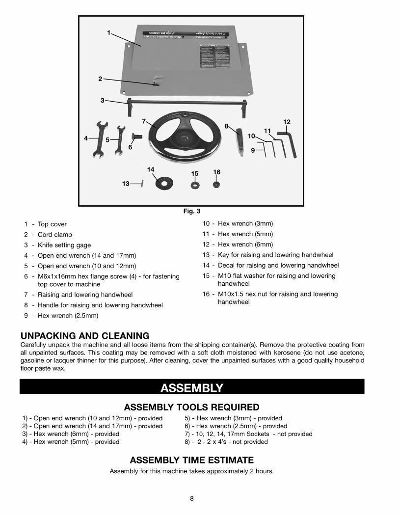
Figure 3 Illustrates the loose items supplied with yourmachine.
Fig. 2
NOTICE: The photo on the manual cover illustarates the current production model. All other illustrations contained inthe manual are representative only and may not depict the actual labeling or accessories included. These are areintended to illustrate technique only.
8
1 - Top cover
2 - Cord clamp
3 - Knife setting gage
4 - Open end wrench (14 and 17mm)
5 - Open end wrench (10 and 12mm)
6 - M6x1x16mm hex flange screw (4) - for fastening top cover to machine
7 - Raising and lowering handwheel
8 - Handle for raising and lowering handwheel
9 - Hex wrench (2.5mm)
10 - Hex wrench (3mm)
11 - Hex wrench (5mm)
12 - Hex wrench (6mm)
13 - Key for raising and lowering handwheel
14 - Decal for raising and lowering handwheel
15 - M10 flat washer for raising and lowering handwheel
16 - M10x1.5 hex nut for raising and lowering handwheel
Fig. 3
1
2
3
4 56
78
9
1011
12
13
1415 16
UNPACKING AND CLEANINGCarefully unpack the machine and all loose items from the shipping container(s). Remove the protective coating fromall unpainted surfaces. This coating may be removed with a soft cloth moistened with kerosene (do not use acetone,gasoline or lacquer thinner for this purpose). After cleaning, cover the unpainted surfaces with a good quality householdfloor paste wax.
ASSEMBLY
ASSEMBLY TOOLS REQUIRED
ASSEMBLY TIME ESTIMATE
1) - Open end wrench (10 and 12mm) - provided 5) - Hex wrench (3mm) - provided2) - Open end wrench (14 and 17mm) - provided 6) - Hex wrench (2.5mm) - provided3) - Hex wrench (6mm) - provided 7) - 10, 12, 14, 17mm Sockets - not provided4) - Hex wrench (5mm) - provided 8) - 2 - 2 x 4’s - not provided
Assembly for this machine takes approximately 2 hours.

9
CUTTINGHEAD RAISING ANDLOWERING HANDWHEEL
1. Insert key (A) Fig. 7, into keyway (B) of raising andlowering shaft.
Fig. 7
Fig. 8
2. Assemble handwheel (C) Fig. 8, to raising and lower-ing shaft as shown. Make sure key, which wasassembled to shaft in STEP 1, is engaged with keywayin hub of handwheel (C).
3. Assemble decal (D) Fig. 8, to raising and loweringshaft as shown.
4. Fasten handwheel (C) Fig. 8, to raising and loweringshaft using an M10 flat washer (E) and an M10 hex nut(F) supplied.
5. Assemble handle (G) Fig. 8, to handwheel (C) asshown.
B
A
G
C
D F
E
LIFTING THE MACHINE
1. IMPORTANT: CARE MUST BE TAKEN WHENLIFTING THE MACHINE ONTO A STAND ORWORKBENCH. THE PLANER IS VERY HEAVY AND AMINIMUM OF FOUR PEOPLE WILL BE REQUIREDTO LIFT THE MACHINE AS FOLLOWS:
2. Raise the cuttinghead (A) Fig. 10, by turning theraising and lowering handwheel (B) clockwise, and inserttwo 6 or 8 foot long 2 x 4’s (C) between the cuttingheadand table as shown. Lower the cuttinghead just until ittouches the 2 x 4 ‘s (C) Fig. 10, so that they arepositioned solidly between the table and cuttinghead.Then with two people on each end of the 2 x 4’s, movethe machine to its desired location.
Fig. 10
CA
B
6. Loosen two head locking knobs, one of which isshown at (G) Fig. 9, and turn handwheel assembly (H)clockwise to raise head assembly. Remove the protectiveshipping block (J).
Fig. 9
J
H
G
FOR YOUR OWN SAFETY, DO NOT CONNECT THE MACHINE TO THE POWER SOURCE UNTIL THEMACHINE IS COMPLETELY ASSEMBLED AND YOU READ AND UNDERSTAND THE ENTIRE INSTRUCTIONMANUAL.
10
ASSEMBLING TOP COVER ANDDUST CHUTE
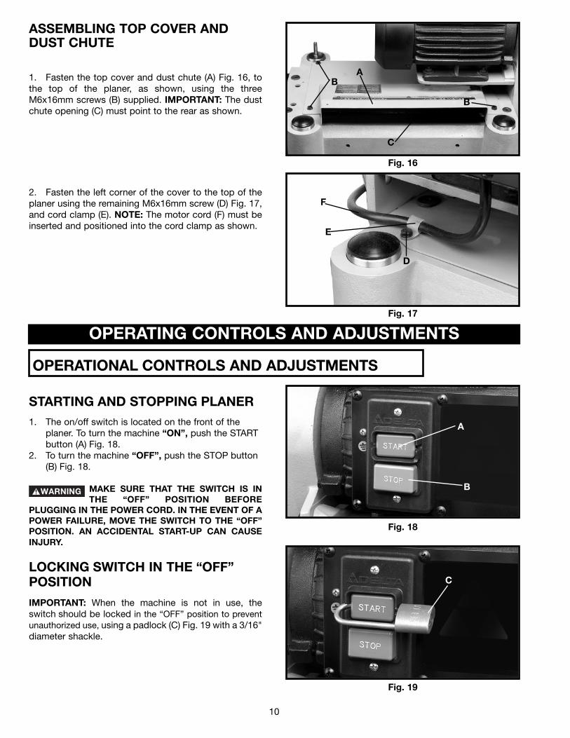
1. Fasten the top cover and dust chute (A) Fig. 16, tothe top of the planer, as shown, using the threeM6x16mm screws (B) supplied. IMPORTANT: The dustchute opening (C) must point to the rear as shown.
Fig. 16
Fig. 17
2. Fasten the left corner of the cover to the top of theplaner using the remaining M6x16mm screw (D) Fig. 17,and cord clamp (E). NOTE: The motor cord (F) must beinserted and positioned into the cord clamp as shown.
D
E
F
B
B
C
A
OPERATING CONTROLS AND ADJUSTMENTS
Fig. 18
A
B
Fig. 19
C
STARTING AND STOPPING PLANER1. The on/off switch is located on the front of the
planer. To turn the machine “ON”, push the STARTbutton (A) Fig. 18.
2. To turn the machine “OFF”, push the STOP button(B) Fig. 18.
MAKE SURE THAT THE SWITCH IS INTHE “OFF” POSITION BEFORE
PLUGGING IN THE POWER CORD. IN THE EVENT OF APOWER FAILURE, MOVE THE SWITCH TO THE “OFF”POSITION. AN ACCIDENTAL START-UP CAN CAUSEINJURY.
LOCKING SWITCH IN THE “OFF”POSITION
IMPORTANT: When the machine is not in use, theswitch should be locked in the “OFF” position to preventunauthorized use, using a padlock (C) Fig. 19 with a 3/16"diameter shackle.
OPERATIONAL CONTROLS AND ADJUSTMENTS

11
DEPTH OF CUT ADJUSTMENTThe depth of cut on your planer is controlled by raisingor lowering the head assembly (A) Fig. 22, whichcontains the cutterhead and feed rollers. The headassembly (A) moves on four precision ground steelcolumns, three of which are shown at (B). To adjust fordepth of cut, simply loosen the two head assembly lockknobs, one of which is shown at (C), and turn the headraising and lowering handwheel (D). Turning thehandwheel (D) clockwise, raises the head assembly andcounterclockwise, lowers the head assembly. Thentighten the two head assembly lock knobs (C).
The maximum depth of cut when planing stock narrowerthan 6 inches wide is 3/16" when the stock is runthrough the planer on one side or the other of thecutterhead. A limiter (E) Fig. 22, is provided to limit thedepth of cut to 1/8" on stock wider than 6 inches.
Fig. 22
Fig. 23
Fig. 24
FEED SPEED CONTROLCHANGE SPEEDS ONLY WHILE THE
MOTOR IS RUNNING. DO NOT CHANGE SPEEDSWHILE PLANING.
Two feed roll speeds of 16 and 30 feet per minute areprovided with your planer. Generally speaking, theslower feed rate provides more cuts per inch, thus afiner, smoother finish of the workpiece is obtained. Agood rule to follow would be to operate the machine atthe faster feed rate for general planing and switch to theslower feed rate for the final finished dimension of theworkpiece. When planing wide stock (wider than 8")particularly in hard wood, the slower feed speed is moredesirable as there is less strain on the motor and a betterfinish is obtained since there are more cuts per inch ofstock length.
When the shifter knob (A) Fig. 24, is pushed all the wayin as shown, the feed speed will be 30 feet per minute.
Fig. 25 Fig. 26
When the shifter knob (A) Fig. 25, is pulled all the wayout as shown, the feed speed will be 16 feet per minute.
When the shifter knob (A) Fig. 26, is in the center(neutral) position as shown, the machine will stopfeeding.
D B
B
B
C
A
A
E
A
A

12
ANTI-KICKBACK FINGERSWHEN INSPECTING AND CLEANINGTHE ANTI-KICKBACK FINGERS, MAKE
SURE THE MACHINE IS DISCONNECTED FROM THEPOWER SOURCE.
A series of anti-kickback fingers (A) Fig. 27, are providedon the infeed end of the planer, to prevent kickback ofthe workpiece during the planing operation. These anti-kickback fingers operate by gravity and no adjustment isrequired. It is necessary, however, to inspect themoccasionally to make sure they are free of gum and pitchand that they move independently and operate correctly. Fig. 27
ADJUSTINGBELT TENSION
DISCONNECT MACHINE FROM POWERSOURCE.
1. Remove four screws (A) Fig. 28, and remove the beltand pulley guard cover (B).2. Place a 2 x 4 (D) Fig. 29, between the motor plateand the top of the head casting as shown.3. Loosen the four screws (C) Fig. 29, and pry up onmotor plate until correct belt tension is obtained. Correcttension is when there is approximately 1/4" deflection inthe center span of the belts using light finger pressure.Then tighten the three screws (C) and replace belt andpulley guard cover (B) Fig. 28.
Fig. 28
Fig. 29
B
A
A
A
D
C
C
Fig. 30Fig. 31
A
B
A
AB
CHECKING, ADJUSTING ANDREPLACING KNIVES
IF THE KNIVES ARE TO BE REMOVEDFOR SHARPENING OR REPLACE-
MENT, EXTREME CARE SHOULD BE TAKEN AS THEKNIVES ARE VERY SHARP. TO REMOVE THEKNIVES, WEAR GLOVES AND PROCEED ASFOLLOWS:
1. DISCONNECT MACHINE FROMPOWER SOURCE.
2. Remove four screws (A) Fig. 30 and Fig. 31, andremove top cover (B).3. Loosen two screws (C) Fig. 32, and pivot motor as-sembly (D) to the front. NOTE: Belt tension is notdisturbed when pivoting the motor forward.
13
Fig. 32
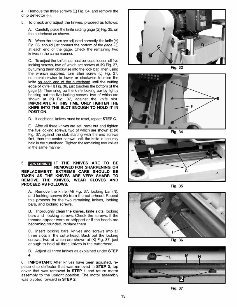
4. Remove the three screws (E) Fig. 34, and remove thechip deflector (F).
5. To check and adjust the knives, proceed as follows:
A. Carefully place the knife setting gage (G) Fig. 35, onthe cutterhead as shown.
B. When the knives are adjusted correctly, the knife (H)Fig. 36, should just contact the bottom of the gage (J),at each end of the gage. Check the remaining twoknives in the same manner.
C. To adjust the knife that must be reset, loosen all fivelocking screws, two of which are shown at (K) Fig. 37,by turning them clockwise into the lock bar. Then usingthe wrench supplied, turn allen screw (L) Fig. 37,counterclockwise to lower or clockwise to raise theknife on each end of the cutterhead until the cuttingedge of knife (H) Fig. 36, just touches the bottom of thegage (J). Then snug up the knife locking bar by lightlybacking out the five locking screws, two of which areshown at (K) Fig. 37, against the knife slot.IMPORTANT: AT THIS TIME, ONLY TIGHTEN THEKNIFE INTO THE SLOT ENOUGH TO HOLD IT INPOSITION.
D. If additional knives must be reset, repeat STEP C.
E. After all three knives are set, back out and tightenthe five locking screws, two of which are shown at (K)Fig. 37, against the slot, starting with the end screwsfirst, then the center screws until the knife is securelyheld in the cutterhead. Tighten the remaining two knivesin the same manner.
C D
Fig. 34
E
F
Fig. 35
G
Fig. 36
J
H
Fig. 37
L
K
M N
5. IF THE KNIVES ARE TO BEREMOVED FOR SHARPENING OR
REPLACEMENT, EXTREME CARE SHOULD BETAKEN AS THE KNIVES ARE VERY SHARP. TOREMOVE THE KNIVES, WEAR GLOVES ANDPROCEED AS FOLLOWS:
A. Remove the knife (M) Fig. 37, locking bar (N),and locking screws (K) from the cutterhead. Repeatthis process for the two remaining knives, lockingbars, and locking screws.
B. Thoroughly clean the knives, knife slots, lockingbars and locking screws. Check the screws. If thethreads appear worn or stripped or if the heads arebecoming rounded, replace them.
C. Insert locking bars, knives and screws into allthree slots in the cutterhead. Back out the lockingscrews, two of which are shown at (K) Fig. 37, justenough to hold all three knives in the cutterhead.
D. Adjust all three knives as explained under STEP4.
6. IMPORTANT: After knives have been adjusted, re-place chip deflector that was removed in STEP 3, topcover that was removed in STEP 1 and return motorassembly to the upright position. The motor assemblywas pivoted forward in STEP 2.
14
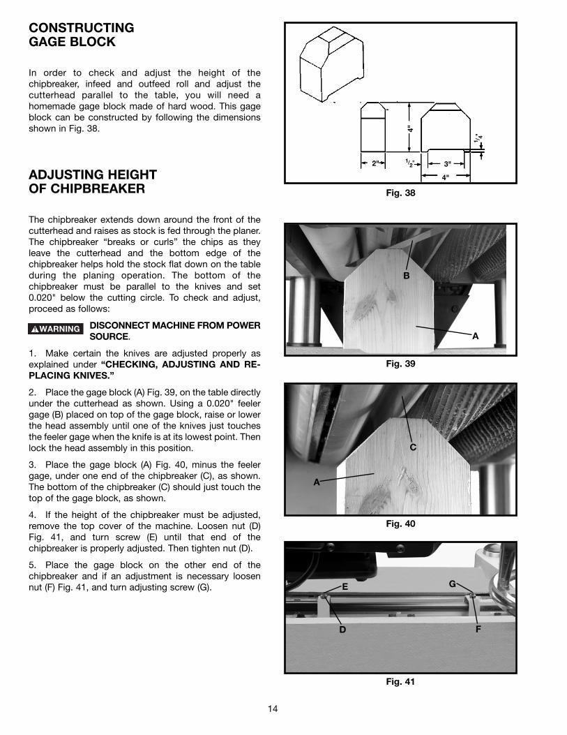
CONSTRUCTINGGAGE BLOCK
In order to check and adjust the height of thechipbreaker, infeed and outfeed roll and adjust thecutterhead parallel to the table, you will need ahomemade gage block made of hard wood. This gageblock can be constructed by following the dimensionsshown in Fig. 38.
Fig. 38
2" 1/2"
1 /4"
4"
3"
4"
Fig. 39
Fig. 40
Fig. 41
E
D
G
F
B
A
C
A
ADJUSTING HEIGHTOF CHIPBREAKER
The chipbreaker extends down around the front of thecutterhead and raises as stock is fed through the planer.The chipbreaker “breaks or curls” the chips as theyleave the cutterhead and the bottom edge of thechipbreaker helps hold the stock flat down on the tableduring the planing operation. The bottom of thechipbreaker must be parallel to the knives and set0.020" below the cutting circle. To check and adjust,proceed as follows:
DISCONNECT MACHINE FROM POWERSOURCE.
1. Make certain the knives are adjusted properly asexplained under “CHECKING, ADJUSTING AND RE-PLACING KNIVES.”
2. Place the gage block (A) Fig. 39, on the table directlyunder the cutterhead as shown. Using a 0.020" feelergage (B) placed on top of the gage block, raise or lowerthe head assembly until one of the knives just touchesthe feeler gage when the knife is at its lowest point. Thenlock the head assembly in this position.
3. Place the gage block (A) Fig. 40, minus the feelergage, under one end of the chipbreaker (C), as shown.The bottom of the chipbreaker (C) should just touch thetop of the gage block, as shown.
4. If the height of the chipbreaker must be adjusted,remove the top cover of the machine. Loosen nut (D)Fig. 41, and turn screw (E) until that end of thechipbreaker is properly adjusted. Then tighten nut (D).
5. Place the gage block on the other end of thechipbreaker and if an adjustment is necessary loosennut (F) Fig. 41, and turn adjusting screw (G).

15
ADJUSTING HEIGHTOF INFEED ROLLERThe infeed roller is adjusted at the factory at 0.040"below the cutting circle. To check and adjust theheight of the infeed roller, proceed as follows:
DISCONNECT MACHINE FROM POWERSOURCE.
1. Make sure the knives are adjusted properly as ex-plained under “CHECKING, ADJUSTING AND RE-PLACING KNIVES.”
2. Place the gage block (A) Fig. 42, on the table directlyunderneath the cutterhead, as shown. Using a 0.040"feeler gage (B) placed on top of the gage block, raise orlower the head assembly until one of the knives justtouches the feeler gage when the knife is at its lowestpoint. Then tighten the head locking knobs.
3. Move the gage block (A) Fig. 43, minus the feelergage, under one end of the infeed roller (C). The bottomof the infeed roller (C) should just touch the top of thegage block (A), as shown.
4. If the height of the infeed roller must be adjusted,loosen nut (D) Fig. 43, and turn adjusting screw (E) untilthat end of the infeed roller just touches the top of thegage block. Then tighten nut (D).
5. Repeat this adjustment with the gage block on theopposite end of the infeed roller.
Fig. 42
Fig. 43
Fig. 44
Fig. 45
ADJUSTING HEIGHTOF OUTFEED ROLLERThe outfeed roller is adjusted at the factory to be 0.040"below the cutting circle. To check and adjust theheight of the outfeed roller, proceed as follows:
DISCONNECT MACHINE FROM POWERSOURCE.
1. Make sure the knives are adjusted properly as ex-plained under “CHECKING, ADJUSTING AND RE-PLACING KNIVES.”
2. Place the gage block (A) Fig. 44, on the table directlyunderneath the cutterhead, as shown. Using a 0.040"feeler gage (B) Fig. 44, placed on top of the gage blockas shown, raise or lower the head assembly until one ofthe knives just touches the feeler gage when the knife isat its lowest point. Then tighten the head locking knobs.
3. Move the gage block (A) Fig. 45, minus the feelergage, under the end of the outfeed roller (C). The bottomof the out-feed roller (C) should just touch the top of thegage block (A).
4. If the height of the outfeed roller must be adjusted,loosen nut (D) Fig. 45, and turn screw (E) until theoutfeed roller is properly adjusted.
5. Repeat this adjustment procedure on the oppositeend of the outfeed roller in the same manner.
B
A
D
E
A
C
B
A
C
A
D
E

16
ADJUSTING SPRING TENSION OFINFEED AND OUTFEED ROLLERS
The infeed and outfeed rollers are those parts of yourplaner that feed the stock while it is being planed. Thefeed rollers are under spring tension and this tensionmust be sufficient to feed the stock uniformly throughthe planer without slipping but should not be too tightthat it causes damage to the board. The tension shouldalso be equal at both ends of each roller.To adjust the spring tension of the infeed roller, turn twoscrews, one of which is shown at (A) Fig. 46. The otherscrew is located on the opposite side of the machine. Agood starting point to use in setting the spring tension ofthe infeed roller is to adjust the two screws (A) until thereare FOUR threads showing above the table casting. Toincrease or decrease the spring tension further, adjustscrews (A).To adjust the spring tension of the outfeed roller, turntwo screws, one of which is shown at (B) Fig. 46. Theother screw is located on the opposite side of themachine. A good starting point to use in setting thespring tension of the outfeed roller is to adjust the twoscrews (B) until there is ONE thread showing above thetable casting. To increase or decrease the spring tensionfurther, adjust screws (B).
Fig. 46
Fig. 47
Fig. 48
ADJUSTING TABLE ROLLERS
Your planer is supplied with two table rollers (A) Fig. 47,which aid in feeding the stock by reducing friction andturn as the stock is fed through the planer. It is notpossible to give exact dimensions on the proper heightsetting of the table rollers because each type of woodbehaves differently. As a general rule, however, whenplaning rough stock the table rollers should be set HIGH(0.003" to 0.005") above the table surface and whenplaning finish stock the table rollers should be set LOW,0.001" above the table surface or level with the tablesurface.The table rollers on your planer are set for averageplaning and are parallel to the table surface. If you desireto adjust the table rollers higher or lower, proceed asfollows:
DISCONNECT MACHINE FROM POWERSOURCE.
Lay a straight edge (B) Fig. 48, across both rollers andwith a feeler gage (C) underneath the straight edge asshown, adjust height of table rollers by loosening setscrews (D) Fig. 47, and turn screws (E) to raise or lowertable rollers (A). Table rollers must be adjusted on theopposite side of table in the same manner. The tablerollers must always be set parallel to the table.IMPORTANT: The adjustment screws (E) Fig. 47, onboth sides of the planer are on eccentrics and careshould be taken when adjusting to keep the rollersfrom leading the stock to one side or the other. Thiscan be accomplished by turning screws (E) Fig. 47,clockwise to raise or lower the rollers and turningthe two screws on the opposite end of the rollerscounterclockwise or vice versa.
AB
A
D
D
E E
B
C
17
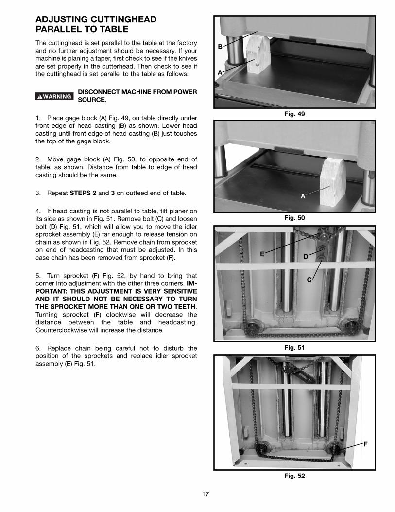
ADJUSTING CUTTINGHEADPARALLEL TO TABLEThe cuttinghead is set parallel to the table at the factoryand no further adjustment should be necessary. If yourmachine is planing a taper, first check to see if the knivesare set properly in the cutterhead. Then check to see ifthe cuttinghead is set parallel to the table as follows:
DISCONNECT MACHINE FROM POWERSOURCE.
1. Place gage block (A) Fig. 49, on table directly underfront edge of head casting (B) as shown. Lower headcasting until front edge of head casting (B) just touchesthe top of the gage block.
2. Move gage block (A) Fig. 50, to opposite end oftable, as shown. Distance from table to edge of headcasting should be the same.
3. Repeat STEPS 2 and 3 on outfeed end of table.
4. If head casting is not parallel to table, tilt planer onits side as shown in Fig. 51. Remove bolt (C) and loosenbolt (D) Fig. 51, which will allow you to move the idlersprocket assembly (E) far enough to release tension onchain as shown in Fig. 52. Remove chain from sprocketon end of headcasting that must be adjusted. In thiscase chain has been removed from sprocket (F).
5. Turn sprocket (F) Fig. 52, by hand to bring thatcorner into adjustment with the other three corners. IM-PORTANT: THIS ADJUSTMENT IS VERY SENSITIVEAND IT SHOULD NOT BE NECESSARY TO TURNTHE SPROCKET MORE THAN ONE OR TWO TEETH.Turning sprocket (F) clockwise will decrease thedistance between the table and headcasting.Counterclockwise will increase the distance.
6. Replace chain being careful not to disturb theposition of the sprockets and replace idler sprocketassembly (E) Fig. 51.
Fig. 49
Fig. 50
Fig. 51
Fig. 52
B
A
A
C
DE
F

MAINTENANCE
Fig. 53 Fig. 54
A
B
Fig. 55
E
C
D
Fig. 56
F
LUBRICATIONThe gear box oil should be changed once a year. Useextreme pressure gear oil, available from Delta in onepint cans (you will need approximately 20 oz.). The gearbox drain plug is shown at (A) Fig. 53. The oil fill andlevel plug is shown at (B) Fig. 54.The four raising screws, two of which are shown at (C)
When using your machine, you may want to follow these few simple steps for achieving the best results possible.1. True Up One Face – Feed one face of the board over a jointer, making thin cuts with each pass, until the entiresurface is flat.2. Plane to Thickness – Place the side you just surfaced in STEP 1 face down and feed the board through the planer,plane until this side is flat. Then plane both sides of the board until you are satisfied with the thickness, making thincuts, alternating sides with each pass. If during the planing operation you notice the board twisting, warping or bowing,repeat STEP 1 and true up one face.3. When planing long stock, provide table extensions to support the infeed and outfeed end of the workpiece.4. For best results, always engage cutterhead lock before planing, plane with the grain only, and keep planer table clean.Occasionally, wax table surface to reduce friction during the planing operation.5. Cross-cut to Final Length – Cross-cut lumber to final length.
THE KNIVES ON THE PLANER WILL NOT WEAR EVENLY BY FEEDING THE WOOD THROUGHTHE SAME SPOT ON THE TABLE EVERY TIME. FEED THE WOOD THROUGH THE PLANER AT
DIFFERENT SPOTS ON THE TABLE WHEN POSSIBLE, TO HELP ELIMINATE UNEVEN WEAR OF THE KNIVES.
MACHINE USE
TROUBLESHOOTINGFor assistance with your machine, visit our website at www.deltamachinery.com for a list of service centers or callthe DELTA Machinery help line at 1-800-223-7278 (In Canada call 1-800-463-3582).
18
Fig. 55, should be lubricated as required using acommon grease.Periodically remove screw (D) Fig. 55, and side cover(E). Thoroughly clean chains and sprockets (F) Fig. 56,and lubricate using a light machine oil. Replace sidecover (E) Fig. 55, and secure with screw (D).

19
KEEP MACHINE CLEANPeriodically blow out all air passages with dry compressedair. All plastic parts should be cleaned with a soft dampcloth. NEVER use solvents to clean plastic parts. They couldpossibly dissolve or otherwise damage the material.
Wear ANSI Z87.1 safety glasses whileusing compressed air.
FAILURE TO STARTShould your machine fail to start, check to make sure theprongs on the cord plug are making good contact in theoutlet. Also, check for blown fuses or open circuit breakersin the line.
TABLE LUBRICATIONApply household floor paste wax to the machine table andextension table or other work surface weekly.
PROTECTING CAST IRON FROM RUST
To clean and protect cast iron tables from rust, you willneed the following materials: 1 pushblock from a jointer,1 sheet of medium Scotch-Brite™ Blending Hand Pad, 1can of WD-40®, 1 can of degreaser, 1 can of TopCote®
Aerosol. Apply the WD-40 and polish the table surfacewith the Scotch-Brite pad using the pushblock as aholddown. Degrease the table, then apply the TopCote®
accordingly.
PARTS, SERVICE OR WARRANTY ASSISTANCEAll Delta Machines and accessories are manufactured to high quality standards and are serviced by a networkof Porter-Cable • Delta Factory Service Centers and Delta Authorized Service Stations. To obtain additionalinformation regarding your Delta quality product or to obtain parts, service, warranty assistance, or the locationof the nearest service outlet, please call 1-800-223-7278 (In Canada call 1-800-463-3582).
A complete line of accessories is available from your Delta Supplier, Porter-Cable • Delta Factory Service Centers,and Delta Authorized Service Stations. Please visit our Web Site www.deltamachinery.com for a catalog orfor the name of your nearest supplier.
Since accessories other than those offered by Delta have not been tested with this product, use of such accessories could be hazardous. For safest operation, only Delta recommended accessories should be used with this product.
ACCESSORIES
Two Year Limited New Product WarrantyDelta will repair or replace, at its expense and at its option, any new Delta machine, machine part, or machine accessorywhich in normal use has proven to be defective in workmanship or material, provided that the customer returns the productprepaid to a Delta factory service center or authorized service station with proof of purchase of the product within twoyears and provides Delta with reasonable opportunity to verify the alleged defect by inspection. For all refurbished Deltaproduct, the warranty period is 180 days. Delta may require that electric motors be returned prepaid to a motormanufacturer’s authorized station for inspection and repair or replacement. Delta will not be responsible for any asserteddefect which has resulted from normal wear, misuse, abuse or repair or alteration made or specifically authorized byanyone other than an authorized Delta service facility or representative. Under no circumstances will Delta be liable forincidental or consequential damages resulting from defective products. This warranty is Delta’s sole warranty and setsforth the customer’s exclusive remedy, with respect to defective products; all other warranties, express or implied, whetherof merchantability, fitness for purpose, or otherwise, are expressly disclaimed by Delta.
SERVICE
WARRANTY

The following are trademarks of PORTER-CABLE • DELTA (Las siguientes son marcas registradas de PORTER-CABLE • DELTA S.A.) (Les marquessuivantes sont des marques de fabriquant de la PORTER-CABLE • DELTA): Auto-Set®, BAMMER®, B.O.S.S.®, Builder’s Saw®, Contractor’s Saw®,Contractor’s Saw II™, Delta®, DELTACRAFT®, DELTAGRAM™, Delta Series 2000™, DURATRONIC™, Emc²™, FLEX®, Flying Chips™, FRAME SAW®,Grip Vac™, Homecraft®, INNOVATION THAT WORKS®, Jet-Lock®, JETSTREAM®, ‘kickstand®, LASERLOC®, MICRO-SET®, Micro-Set®, MIDI LATHE®,MORTEN™, NETWORK™, OMNIJIG®, POCKET CUTTER®, PORTA-BAND®, PORTA-PLANE®, PORTER-CABLE®&(design), PORTER-CABLE®PROFESSIONAL POWER TOOLS, PORTER-CABLE REDEFINING PERFORMANCE™, Posi-Matic®, Q-3®&(design), QUICKSAND®&(design),QUICKSET™, QUICKSET II®, QUICKSET PLUS™, RIPTIDE™&(design), SAFE GUARD II®, SAFE-LOC®, Sanding Center®, SANDTRAP®&(design), SAWBOSS®, Sawbuck™, Sidekick®, SPEED-BLOC®, SPEEDMATIC®, SPEEDTRONIC®, STAIR EASE®, The American Woodshop®&(design), The LumberCompany®&(design), THE PROFESSIONAL EDGE®, THE PROFESSIONAL SELECT®, THIN-LINE™, TIGER®, TIGER CUB®, TIGER SAW®,TORQBUSTER®, TORQ-BUSTER®, TRU-MATCH™, TWIN-LITE®, UNIGUARD®, Unifence®, UNIFEEDER™, Unihead®, Uniplane™, Unirip®, Unisaw®,Univise®, Versa-Feeder®, VERSA-PLANE® , WHISPER SERIES®, WOODWORKER’S CHOICE™. Trademarks noted with ™ and ® are registered in the United States Patent and Trademark Office and may also be registered in other countries. LasMarcas Registradas con el signo de ™ y ® son registradas por la Oficina de Registros y Patentes de los Estados Unidos y también pueden estarregistradas en otros países.
PORTER-CABLE • DELTA SERVICE CENTERS(CENTROS DE SERVICIO DE PORTER-CABLE • DELTA)
Parts and Repair Service for Porter-Cable • Delta Machinery are Available at These Locations(Obtenga Refaccion de Partes o Servicio para su Herramienta en los Siguientes Centros de Porter-Cable • Delta)
Authorized Service Stations are located in many large cities. Telephone 800-438-2486 or 731-541-6042 for assistance locating one.Parts and accessories for Porter-Cable·Delta products should be obtained by contacting any Porter-Cable·Delta Distributor, AuthorizedService Center, or Porter-Cable·Delta Factory Service Center. If you do not have access to any of these, call 800-223-7278 and you willbe directed to the nearest Porter-Cable·Delta Factory Service Center. Las Estaciones de Servicio Autorizadas están ubicadas en muchasgrandes ciudades. Llame al 800-438-2486 ó al 731-541-6042 para obtener asistencia a fin de localizar una. Las piezas y los accesoriospara los productos Porter-Cable·Delta deben obtenerse poniéndose en contacto con cualquier distribuidor Porter-Cable·Delta, Centrode Servicio Autorizado o Centro de Servicio de Fábrica Porter-Cable·Delta. Si no tiene acceso a ninguna de estas opciones, llame al800-223-7278 y le dirigirán al Centro de Servicio de Fábrica Porter-Cable·Delta más cercano.
ARIZONAPhoenix 85013-29064501 N. 7th Ave.Phone: (602) 279-6414Fax: (602) 279-5470
CALIFORNIAOntario 91761 (Los Angeles)3949A East Guasti RoadPhone: (909) 390-5555Fax: (909) 390-5554
San Diego 921117290 Clairemont Mesa Blvd.Phone: (858) 279-2011Fax: (858) 279-0362
San Leandro 94577 (Oakland)3039 Teagarden StreetPhone: (510) 357-9762Fax: (510) 357-7939
COLORADODenver 80223700 West Mississippi Ave.Phone: (303) 922-8325Fax: (303) 922-0245
FLORIDADavie 33314 (Miami)4343 South State Rd. 7 (441)Unit #107Phone: (954) 321-6635Fax: (954) 321-6638
Tampa 336344909 West Waters Ave.Phone: (813) 884-0434Fax: (813) 888-5997
GEORGIAForest Park 30297 (Atlanta)5442 Frontage Road,Suite 112Phone: (404) 608-0006Fax: (404) 608-1123
ILLINOISAddison 60101 (Chicago)400 South Rohlwing Rd.Phone: (630) 424-8805Fax: (630) 424-8895
KANSASOverland Park 662149201 Quivira RoadPhone: (913) 495-4330Fax: (913) 495-4378
MARYLANDElkridge 21075 (Baltimore)7397-102 Washington Blvd.Phone: (410) 799-9394Fax: (410) 799-9398
MASSACHUSETTSFranklin 02038 (Boston)Franklin Industrial Park101E Constitution Blvd.Phone: (508) 520-8802Fax: (508) 528-8089
MICHIGANMadison Heights 48071 (Detroit)30475 Stephenson HighwayPhone: (248) 597-5000Fax: (248) 597-5004
MINNESOTAEden Prairie 553449709 Valley View RoadPhone: (952) 884-9191Fax: (952) 884-3750
MISSOURISt. Louis 6314611477 Page Service DrivePhone: (314) 997-9100Fax: (314) 997-9183
NEW YORKFlushing 11365-1595 (N.Y.C.)175-25 Horace Harding Expwy.Phone: (718) 225-2040Fax: (718) 423-9619
NORTH CAROLINACharlotte 282709129 Monroe Road, Suite 115Phone: (704) 841-1176Fax: (704) 708-4625
OHIOColumbus 432291948 Schrock RoadPhone: (614) 895-3112Fax: (614) 895-3187
Parma Heights OH 441306485 Pearl RoadPhone: (440) 842-9100Fax: (440) 884-3430
OREGONPortland 9723014811 North East Airport WayPhone: (503) 255-6556Fax: (503) 255-6543
PENNSYLVANIAWillow Grove 19090(Philadelphia)520 North York RoadPhone: (215) 658-1430Fax: (215) 658-1433
TEXASCarrollton 75006 (Dallas)1300 Interstate 35 N, Suite 112Phone: (972) 446-2996Fax: (972) 446-8157
Houston 77022-2122536 East Tidwell Rd.Phone: (713) 692-7111Fax: (713) 692-1107
WASHINGTONAuburn 98001(Seattle)3320 West Valley HWY, NorthBuilding D, Suite 111Phone: (253) 333-8353Fax: (253) 333-9613
PC7.2-0105-149
CANADIAN PORTER-CABLE • DELTA SERVICE CENTERSALBERTABay 6, 2520-23rd St. N.E.Calgary, AlbertaT2E 8L2Phone: (403) 735-6166Fax: (403) 735-6144
BRITISH COLUMBIA8520 Baxter PlaceBurnaby, B.C.V5A 4T8Phone: (604) 420-0102Fax: (604) 420-3522
MANITOBA1699 Dublin AvenueWinnipeg, ManitobaR3H 0H2Phone: (204) 633-9259Fax: (204) 632-1976
ONTARIO505 Southgate DriveGuelph, OntarioN1H 6M7Phone: (519) 767-4132Fax: (519) 767-4131
QUÉBEC1515 ave.St-Jean Baptiste, Suite 160Québec, QuébecG2E 5E2Phone: (418) 877-7112Fax: (418) 877-7123
1447, BeginSt-Laurent, (Montréal),QuébecH4R 1V8Phone: (514) 336-8772Fax: (514) 336-3505