15-kv wall-mount fuse-gear 200 amp s&c smu-20 …elliott-industries.com/eipdf/b550-116.pdf15-kv...
TRANSCRIPT

15-kV Wall-Mount Fuse-Gear200 Amp S&C SMU-20 and SM-4 Fuses
Three Phase – Indoor/Outdoor
Elliott Industries, Inc. 1509 Hamilton Road Bossier City, LoUiSiAna 71111 [email protected] © Copyright 2015 Phone 318-746-3296 Fax 318-741-1127 www.elliott-industries.com
Bulletin
550-116Page 1 2015
Uni-Rupter® is a registered trademark of S&C Electric Company. Elastimold® is a registered trademark of ABB Asea Brown Boveri Ltd.
DEB86-3E N E R G I Z E D
B U S H I N G SM A Y B E
B U S H I N G S
E N E R G I Z E DDEB86-3
M A Y B E
B U S H I N G S
E N E R G I Z E DM A Y B E
DEB86-3
DEB86-3
B U S H I N G S
E N E R G I Z E DM A Y B E
DEB86-3
B U S H I N G S
E N E R G I Z E DM A Y B E
Elliott air-insulated bushingsaccept IEEE Standardinserts and elbows
Coordinated padlock andpenta-head or optionalhex-head (top and bottom)provides bolted door security with visual confirmation bysupervisory personnel.Security bolt is made captive with a stainless steel washer compressed to an oval shapeto severely discourage removal.
Heavy duty 11-gauge steelenclosure is all weldedconstruction for long life
ENCLOSURE OPTIONS:1) 0.125” #5052H32 Aluminum2) 12-gauge #304L Stainless Steel
Tamper-Resistant Enclosuremeets National and Regional Enclosure Integrity Standards and virtually eliminates the entrance of airborne contamination to reduce maintenance
Superlife FinishIncludes phosphatizing,rust-inhibiting epoxy primerand Pad-Mount Green(Munsell 7GY 3.29/1.5)polyurethane top coat -over 5 mils dry
“In-Air” Insulation eliminates leaking orcontamination ofinsulating medium forlong trouble-freeoperation
“In-Air” Visibilityallows visual inspectionof all components withoutthe inconvenience or expense associated with equipment which must be de-energized for inspection
Clear polycarbonate door safety barrier.Safety latches on the door safety barrier are insulating and require a positiveaction to remove thesafety barrier. Barrier lift handles are insulating and keyed to prevent rotation
Door-holder rods are stainless steel and hold the door open 100 degrees or 140 degrees
Kinked roof prevents standing moisture
Overlapping door andenclosure flanges - with other features - provide tamper resistance to meet national and regional standards
Stainless steel hinges are welded to the door and the enclosure – 0.375” pinsare standard
Corrosion proof nameplateis located to provide easyaccess for the operator
Ground lugs accept#6 - #2/0 ground cable
"Danger - Bushings May Be Energized"
Ground lugs accept#6 - #2/0 ground cable
Glass reinforced barriers meet NEMA GPO-3 Standards
Removable lift provisions with blind holes for tamper resistance
0.625" diameter copper ground bar
Parking stands are unpainted stainless steel and provide space and grounding for feed-thru and other portable devices
15-kV Wall-Mount Fuse-Gear200 Amp S&C SMU-20 and SM-4 Fuses
Three Phase – Indoor/Outdoor
Elliott Industries, Inc. 1509 Hamilton Road Bossier City, LoUiSiAna 71111 [email protected] © Copyright 2015 Phone 318-746-3296 Fax 318-741-1127 www.elliott-industries.com
Bulletin
550-116Page 2 2015
Uni-Rupter® is a registered trademark of S&C Electric Company. Elastimold® is a registered trademark of ABB Asea Brown Boveri Ltd.
A
A
54"
44"42"
40" 34"
CL
CL
18" 18"
28"
3"
20"
20"
7"
10.75"
9"
15"
"Fuses" Label is Visible with Door Closed
Mounting
0.6875" Dia.for 0.625"
ElliottAir-Insulated
Ground Provisions with#6 - #2/0 Eyebolt Type
Ground ConnectorsInstalled Top and Bottom
Bushing Wells
BusCopper
0.625" Dia.Cu. Grd. Bar
GPO-3Barriers
Option G1Grd. Studs
Option G2Grd. Studs
Provision for Padlock andSecurity Bolt, Top and Bottom
ClearPolycarbonateDoor SafetyBarrier
0.50"-13 Hex Nut
Provisions,
Bolts, Typical
Provisionfor KeyInterlock
0.25" x 2"
SMU-20S&C
Fuses
RemovableLift Provisions
Top and Bottom
10.75"
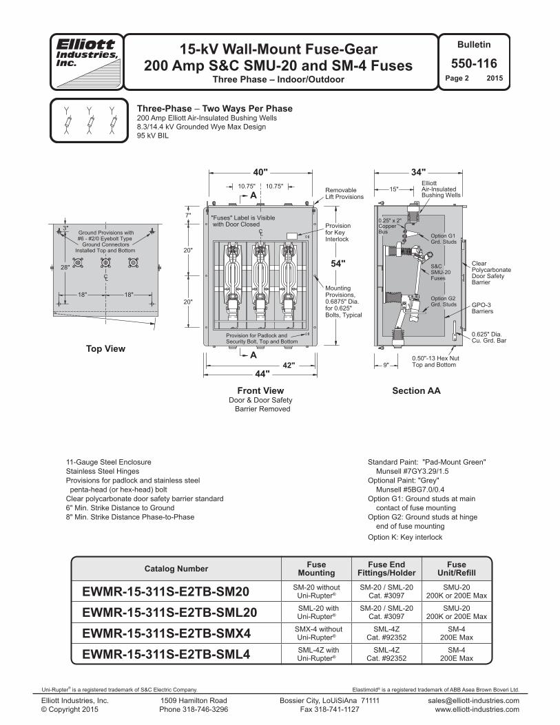
Standard Paint: "Pad-Mount Green" Munsell #7GY3.29/1.5Optional Paint: "Grey" Munsell #5BG7.0/0.4Option G1: Ground studs at main contact of fuse mountingOption G2: Ground studs at hinge end of fuse mounting Option K: Key interlock
Front ViewDoor & Door Safety Barrier Removed
Top View
Section AA
Three-Phase – Two Ways Per Phase200 Amp Elliott Air-Insulated Bushing Wells8.3/14.4 kV Grounded Wye Max Design95 kV BIL
11-Gauge Steel EnclosureStainless Steel HingesProvisions for padlock and stainless steel penta-head (or hex-head) bolt Clear polycarbonate door safety barrier standard6" Min. Strike Distance to Ground8" Min. Strike Distance Phase-to-Phase
Catalog Number FuseMounting
Fuse EndFittings/Holder
FuseUnit/Refill
EWMR-15-311S-E2TB-SM20 SM-20 withoutUni-Rupter®
SM-20 / SML-20Cat. #3097
SMU-20200K or 200E Max
EWMR-15-311S-E2TB-SML20 SML-20 withUni-Rupter®
SM-20 / SML-20Cat. #3097
SMU-20200K or 200E Max
EWMR-15-311S-E2TB-SMX4 SMX-4 withoutUni-Rupter®
SML-4ZCat. #92352
SM-4200E Max
EWMR-15-311S-E2TB-SML4 SML-4Z withUni-Rupter®
SML-4ZCat. #92352
SM-4200E Max
Elastimold® is a registered trademark of ABB Asea Brown Boveri Ltd.
15-kV Wall-Mount Fuse-Gear200 Amp S&C SMU-20 and SM-4 Fuses
Three Phase – Indoor/Outdoor
Elliott Industries, Inc. 1509 Hamilton Road Bossier City, LoUiSiAna 71111 [email protected] © Copyright 2015 Phone 318-746-3296 Fax 318-741-1127 www.elliott-industries.com
Bulletin
550-116Page 3 2015
Uni-Rupter® is a registered trademark of S&C Electric Company. Elastimold® is a registered trademark of ABB Asea Brown Boveri Ltd.
A
A
54"
44"
40" 34"
CL
20"
20"
7" 10.75" 10.75"
9"
15"
8"
42"
Mounting
0.6875" Dia.for 0.625"
ElliottAir-InsulatedBushing Wells
0.625" Dia.Cu. Grd. Bar
GPO-3Barriers
ClearPolycarbonateDoor SafetyBarrier
0.50"-13 Hex Nut
Provisions,
Bolts, Typical
Provision
Interlock
RemovableLift Provisions
Top and Bottom
"Fuses" Label is Visible with Door Closed
for Key BusCopper
Option G2Grd. Studs
Provision for Padlock andSecurity Bolt, Top and Bottom
0.25" x 2"
SMU-20S&C
Fuses
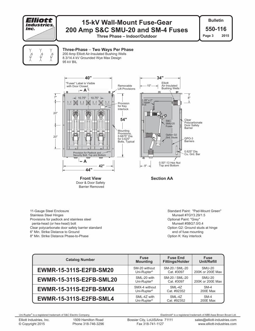
Three-Phase – Two Ways Per Phase200 Amp Elliott Air-Insulated Bushing Wells8.3/14.4 kV Grounded Wye Max Design95 kV BIL
Standard Paint: "Pad-Mount Green" Munsell #7GY3.29/1.5Optional Paint: "Grey" Munsell #5BG7.0/0.4Option G2: Ground studs at hinge end of fuse mounting Option K: Key interlock
11-Gauge Steel EnclosureStainless Steel HingesProvisions for padlock and stainless steel penta-head (or hex-head) boltClear polycarbonate door safety barrier standard6" Min. Strike Distance to Ground8" Min. Strike Distance Phase-to-Phase
Front ViewDoor & Door Safety Barrier Removed
Section AA
Catalog Number FuseMounting
Fuse EndFittings/Holder
FuseUnit/Refill
EWMR-15-311S-E2FB-SM20 SM-20 withoutUni-Rupter®
SM-20 / SML-20Cat. #3097
SMU-20200K or 200E Max
EWMR-15-311S-E2FB-SML20 SML-20 withUni-Rupter®
SM-20 / SML-20Cat. #3097
SMU-20200K or 200E Max
EWMR-15-311S-E2FB-SMX4 SMX-4 withoutUni-Rupter®
SML-4ZCat. #92352
SM-4200E Max
EWMR-15-311S-E2FB-SML4 SML-4Z withUni-Rupter®
SML-4ZCat. #92352
SM-4200E Max

15-kV Wall-Mount Fuse-Gear200 Amp S&C SMU-20 and SM-4 Fuses
Three Phase – Indoor/Outdoor
Elliott Industries, Inc. 1509 Hamilton Road Bossier City, LoUiSiAna 71111 [email protected] © Copyright 2015 Phone 318-746-3296 Fax 318-741-1127 www.elliott-industries.com
Bulletin
550-116Page 4 2015
Uni-Rupter® is a registered trademark of S&C Electric Company. Elastimold® is a registered trademark of ABB Asea Brown Boveri Ltd.
A
A
54"
44"
40" 34"
42"
18" 18"
28"
3"
20"
20"
7"
10.75" 10.75"
9"
15"
CL
CL
"Fuses" Label is Visible with Door Closed
Mounting
0.6875" Dia.for 0.625"
ElliottAir-InsulatedBushings
0.625" Dia.Cu. Grd. Bar
GPO-3Barriers
ClearPolycarbonateDoor SafetyBarrier
0.50"-13 Hex Nut
Provisions,
Bolts, Typical
Provisionfor KeyInterlock
RemovableLift Provisions
Top and Bottom
BusCopper
Option G1Grd. Studs
Option G2Grd. Studs
Provision for Padlock andSecurity Bolt, Top and Bottom
0.25" x 2"
SMU-20S&C
Fuses
Ground Provisions with#6 - #2/0 Eyebolt Type
Ground ConnectorsInstalled Top and Bottom
Three-Phase – Two Ways Per Phase600 Amp Elliott Air-Insulated Bushings200 Amp Elliott Air-Insulated Bushing Wells8.3/14.4 kV Grounded Wye Max Design95 kV BIL
Standard Paint: "Pad-Mount Green" Munsell #7GY3.29/1.5Optional Paint: "Grey" Munsell #5BG7.0/0.4Option G1: Ground studs at main contact of fuse mountingOption G2: Ground studs at hinge end of fuse mounting Option K: Key Interlock
11-Gauge Steel EnclosureStainless Steel HingesProvisions for padlock and stainless steel penta-head (or hex-head) bolt Clear polycarbonate door safety barrier standard6" Min. Strike Distance to Ground8" Min. Strike Distance Phase-to-Phase
Front ViewDoor & Door Safety Barrier Removed
Top View
Section AA
Catalog Number FuseMounting
Fuse EndFittings/Holder
FuseUnit/Refill
EWMR-15-311S-E6T/E2B-SM20 SM-20 withoutUni-Rupter®
SM-20 / SML-20Cat. #3097
SMU-20200K or 200E Max
EWMR-15-311S-E6T/E2B-SML20 SML-20 withUni-Rupter®
SM-20 / SML-20Cat. #3097
SMU-20200K or 200E Max
EWMR-15-311S-E6T/E2B-SMX4 SMX-4 withoutUni-Rupter®
SML-4ZCat. #92352
SM-4200E Max
EWMR-15-311S-E6T/E2B-SML4 SML-4Z withUni-Rupter®
SML-4ZCat. #92352
SM-4200E Max

Elastimold® is a registered trademark of ABB Asea Brown Boveri Ltd.
15-kV Wall-Mount Fuse-Gear200 Amp S&C SMU-20 and SM-4 Fuses
Three Phase – Indoor/Outdoor
Elliott Industries, Inc. 1509 Hamilton Road Bossier City, LoUiSiAna 71111 [email protected] © Copyright 2015 Phone 318-746-3296 Fax 318-741-1127 www.elliott-industries.com
Bulletin
550-116Page 5 2015
Uni-Rupter® is a registered trademark of S&C Electric Company. Elastimold® is a registered trademark of ABB Asea Brown Boveri Ltd.
A
A
54"
44"
40" 34"
42"
20"
20"
7"
9"
15"
8"10.75" 10.75"
CL
"Fuses" Label is Visible with Door Closed
Mounting
0.6875" Dia.for 0.625"
ElliottAir-InsulatedBushings
0.625" Dia.Cu. Grd. Bar
GPO-3Barriers
ClearPolycarbonateDoor SafetyBarrier
0.50"-13 Hex Nut
Provisions,
Bolts, Typical
Provisionfor KeyInterlock
RemovableLift Provisions
Top and Bottom
BusCopper
Option G2Grd. Studs
Provision for Padlock andSecurity Bolt, Top and Bottom
0.25" x 2"
SMU-20S&C
Fuses
Three-Phase – Two Ways Per Phase600 Amp Elliott Air-Insulated Bushings200 Amp Elliott Air-Insulated Bushing Wells8.3/14.4 kV Grounded Wye Max Design95 kV BIL
Standard Paint: "Pad-Mount Green" Munsell #7GY3.29/1.5Optional Paint: "Grey" Munsell #5BG7.0/0.4Option G2: Ground studs at hinge end of fuse mounting Option K: Key interlock
11-Gauge Steel EnclosureStainless Steel HingesProvisions for padlock and stainless steel penta-head (or hex-head) bolt Clear polycarbonate door safety barrier standard6" Min. Strike Distance to Ground8" Min. Strike Distance Phase-to-Phase
Front ViewDoor & Door Safety Barrier Removed
Section AA
Catalog Number FuseMounting
Fuse EndFittings/Holder
FuseUnit/Refill
EWMR-15-311S-E6F/E2B-SM20 SM-20 withoutUni-Rupter®
SM-20 / SML-20Cat. #3097
SMU-20200K or 200E Max
EWMR-15-311S-E6F/E2B-SML20 SML-20 withUni-Rupter®
SM-20 / SML-20Cat. #3097
SMU-20200K or 200E Max
EWMR-15-311S-E6F/E2B-SMX4 SMX-4 withoutUni-Rupter®
SML-4ZCat. #92352
SM-4200E Max
EWMR-15-311S-E6F/E2B-SML4 SML-4Z withUni-Rupter®
SML-4ZCat. #92352
SM-4200E Max
15-kV Wall-Mount Fuse-Gear200 Amp S&C SMU-20 and SM-4 Fuses
Three Phase – Indoor/Outdoor
Elliott Industries, Inc. 1509 Hamilton Road Bossier City, LoUiSiAna 71111 [email protected] © Copyright 2015 Phone 318-746-3296 Fax 318-741-1127 www.elliott-industries.com
Bulletin
550-116Page 6 2015
Uni-Rupter® is a registered trademark of S&C Electric Company. Elastimold® is a registered trademark of ABB Asea Brown Boveri Ltd.
A
A
54"
44"
40" 34"
18" 18"
28"
3"
20"
20"
7"
10.75" 10.75"
9"
15"
42"
CL
CL
"Fuses" Label is Visible with Door Closed
Mounting
0.6875" Dia.for 0.625"
ElliottAir-InsulatedBushings
0.625" Dia.Cu. Grd. Bar
GPO-3Barriers
ClearPolycarbonateDoor SafetyBarrier
Provisions,
Bolts, Typical
Provisionfor KeyInterlock
RemovableLift Provisions
BusCopper
Option G1Grd. Studs
Option G2Grd. Studs
Provision for Padlock andSecurity Bolt, Top and Bottom
0.25" x 2"
SMU-20S&C
Fuses
0.50"-13 Hex NutTop and Bottom
Ground Provisions with#6 - #2/0 Eyebolt Type
Ground ConnectorsInstalled Top and Bottom
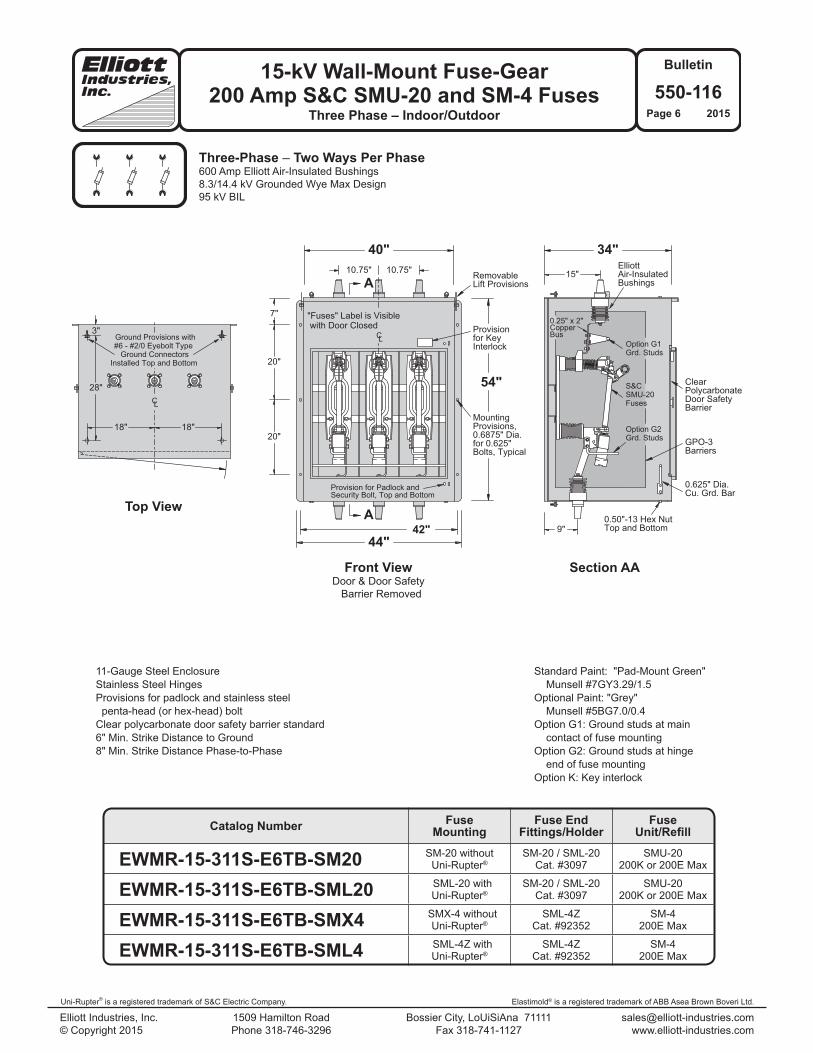
Three-Phase – Two Ways Per Phase600 Amp Elliott Air-Insulated Bushings8.3/14.4 kV Grounded Wye Max Design95 kV BIL
Standard Paint: "Pad-Mount Green" Munsell #7GY3.29/1.5Optional Paint: "Grey" Munsell #5BG7.0/0.4Option G1: Ground studs at main contact of fuse mountingOption G2: Ground studs at hinge end of fuse mounting Option K: Key interlock
11-Gauge Steel EnclosureStainless Steel HingesProvisions for padlock and stainless steel penta-head (or hex-head) boltClear polycarbonate door safety barrier standard6" Min. Strike Distance to Ground8" Min. Strike Distance Phase-to-Phase
Front ViewDoor & Door Safety Barrier Removed
Top View
Section AA
Catalog Number FuseMounting
Fuse EndFittings/Holder
FuseUnit/Refill
EWMR-15-311S-E6TB-SM20 SM-20 withoutUni-Rupter®
SM-20 / SML-20Cat. #3097
SMU-20200K or 200E Max
EWMR-15-311S-E6TB-SML20 SML-20 withUni-Rupter®
SM-20 / SML-20Cat. #3097
SMU-20200K or 200E Max
EWMR-15-311S-E6TB-SMX4 SMX-4 withoutUni-Rupter®
SML-4ZCat. #92352
SM-4200E Max
EWMR-15-311S-E6TB-SML4 SML-4Z withUni-Rupter®
SML-4ZCat. #92352
SM-4200E Max

Elastimold® is a registered trademark of ABB Asea Brown Boveri Ltd.
15-kV Wall-Mount Fuse-Gear200 Amp S&C SMU-20 and SM-4 Fuses
Three Phase – Indoor/Outdoor
Elliott Industries, Inc. 1509 Hamilton Road Bossier City, LoUiSiAna 71111 [email protected] © Copyright 2015 Phone 318-746-3296 Fax 318-741-1127 www.elliott-industries.com
Bulletin
550-116Page 7 2015
Uni-Rupter® is a registered trademark of S&C Electric Company. Elastimold® is a registered trademark of ABB Asea Brown Boveri Ltd.
A
A
54"
44"
40" 34"
20"
20"
7" 10.75" 10.75"
9"
8"
CL
42"
"Fuses" Label is Visible with Door Closed
Mounting
0.6875" Dia.for 0.625"
ElliottAir-InsulatedBushings
0.625" Dia.Cu. Grd. Bar
GPO-3Barriers
ClearPolycarbonateDoor SafetyBarrier
0.50"-13 Hex Nut
Provisions,
Bolts, Typical
Provisionfor KeyInterlock
RemovableLift Provisions
Top and Bottom
BusCopper
Option G2Grd. Studs
Provision for Padlock andSecurity Bolt, Top and Bottom
0.25" x 2"
SMU-20S&C
Fuses
Three-Phase – Two Ways Per Phase600 Amp Elliott Air-Insulated Bushings8.3/14.4 kV Grounded Wye Max Design95 kV BIL
Standard Paint: "Pad-Mount Green" Munsell #7GY3.29/1.5Optional Paint: "Grey" Munsell #5BG7.0/0.4Option G2: Ground studs at hinge end of fuse mounting Option K: Key interlock
11-Gauge Steel EnclosureStainless Steel HingesProvisions for padlock and stainless steel penta-head (or hex-head) boltClear polycarbonate door safety barrier standard6" Min. Strike Distance to Ground8" Min. Strike Distance Phase-to-Phase
Front ViewDoor & Door Safety Barrier Removed
Section AA
Catalog Number FuseMounting
Fuse EndFittings/Holder
FuseUnit/Refill
EWMR-15-311S-E6FB-SM20 SM-20 withoutUni-Rupter®
SM-20 / SML-20Cat. #3097
SMU-20200K or 200E Max
EWMR-15-311S-E6FB-SML20 SML-20 withUni-Rupter®
SM-20 / SML-20Cat. #3097
SMU-20200K or 200E Max
EWMR-15-311S-E6FB-SMX4 SMX-4 withoutUni-Rupter®
SML-4ZCat. #92352
SM-4200E Max
EWMR-15-311S-E6FB-SML4 SML-4Z withUni-Rupter®
SML-4ZCat. #92352
SM-4200E Max

15-kV Wall-Mount Fuse-Gear200 Amp S&C SMU-20 and SM-4 Fuses
Three Phase – Indoor/Outdoor
Elliott Industries, Inc. 1509 Hamilton Road Bossier City, LoUiSiAna 71111 [email protected] © Copyright 2015 Phone 318-746-3296 Fax 318-741-1127 www.elliott-industries.com
Bulletin
550-116Page 8 2015
Uni-Rupter® is a registered trademark of S&C Electric Company. Elastimold® is a registered trademark of ABB Asea Brown Boveri Ltd.
"A"
28"
39.5"
21.5"
36"
A A
2.75"6"
1.75"
0.50"-13 S.S.Hex Nut Typical
Provision forGround Connector
Mounting Provisionsfor Mounting Frame
to Bottom of Enclosurewith Four 0.50"-13 x 1.75"
Hex Head Bolts with0.50" Flat and Split
Lockwashers
Provisions for#6 - #2/0 Eyebolt Type
Ground Connector
0.625" x 1"Obround Typical
33.5"
Elliott Floor Support Frame For Wall-Mount EnclosureProvides Additional Support When Wall Structure
Is Inadequate or Questionable
Top View Section AA
Front View Side View
11-Gauge SteelStandard Paint: "Pad-Mount Green" Munsell #GY3.29/1.5Option Paint: "Grey" Munsell #5BG7.0/0.4
Catalog Number Dimension "A"
EFSF-18-39.5-33.5 18"EFSF-24-39.5-33.5 24"EFSF-30-39.5-33.5 30"EFSF-36-39.5-33.5 36"EFSF-42-39.5-33.5 42"

Elastimold® is a registered trademark of ABB Asea Brown Boveri Ltd.
15-kV Wall-Mount Fuse-Gear200 Amp S&C SMU-20 and SM-4 Fuses
Three Phase – Indoor/Outdoor
Elliott Industries, Inc. 1509 Hamilton Road Bossier City, LoUiSiAna 71111 [email protected] © Copyright 2015 Phone 318-746-3296 Fax 318-741-1127 www.elliott-industries.com
Bulletin
550-116Page 9 2015
Uni-Rupter® is a registered trademark of S&C Electric Company. Elastimold® is a registered trademark of ABB Asea Brown Boveri Ltd.
Voltage Class.................................................. 25 kVPhase-to-Ground Voltage................................ 15.2 kVBIL................................................................... 125 kVAC Withstand—1 Min. Dry............................. 40 kV 10 Sec. Dew......................... 40 kVDC Withstand—15 Min. Dry........................... 78 kVCorona Extinction Level—Minimum................ 19 kVContinuous Current......................................... 200 AmpsMomentary—RMS, Sym., 0.17 sec................. 10,000 Amps RMS, Sym., 3 sec................................... 3,500 Amps
200 Amp Bushing Well #1101-225B
Voltage Class.................................................. 25 kVPhase-to-Ground Voltage................................ 15.2 kVBIL................................................................... 125 kVAC Withstand—1 Min. Dry............................. 40 kV 10 Sec. Dew......................... 40 kVDC Withstand—15 Min. Dry.......................... 78 kVCorona Extinction Level—Minimum................ 19 kV Continuous Current......................................... 600 AmpsMomentary—RMS, Sym., 0.17 sec................. 25,000Amps RMS, Sym., 3 sec................................... 10,000 Amps
600 Amp Bushing #1201-625B2
Bushing Wells and Bushings The wall-mount fuse gear shown in this bulletin is provided with Elliott 200 Amp Air-Insulated Bushing Wells and/or 600 Amp Air-Insulated Bushings which utilize the same mounting holes and mounting hardware. If circuit requirements change, 200 Amp Bushing Wells may be replaced with 600 Amp Bushings (600 Amp Bushings may be replaced with 200 Amp Bushing Wells).
NOTE: The shipping cap on the Bushing Well or Bushing should be left in place to prevent contamination of the interface.
NOTE: The fuse gear must be de-energized and grounded in accordance with your company’s normal safety procedure before any modifications are made.
IMPORTANT: Do not energize this bushing well or bushing with only the shipping cap in place. To do so would lead to failure of this bushing and create a hazard to operating personnel. This product is designed to be used only when it is mated with an appropriate 15 kV or 25 kV class bushing insert (or elbow) conforming to the latest revision of IEEE Standard 386. The bushing insert (or elbow) should be installed in accordance with the instructions supplied by the connector manufacturer.
15-kV Wall-Mount Fuse-Gear200 Amp S&C SMU-20 and SM-4 Fuses
Three Phase – Indoor/Outdoor
Elliott Industries, Inc. 1509 Hamilton Road Bossier City, LoUiSiAna 71111 [email protected] © Copyright 2015 Phone 318-746-3296 Fax 318-741-1127 www.elliott-industries.com
Bulletin
550-116Page 10 2015
Uni-Rupter® is a registered trademark of S&C Electric Company. Elastimold® is a registered trademark of ABB Asea Brown Boveri Ltd.
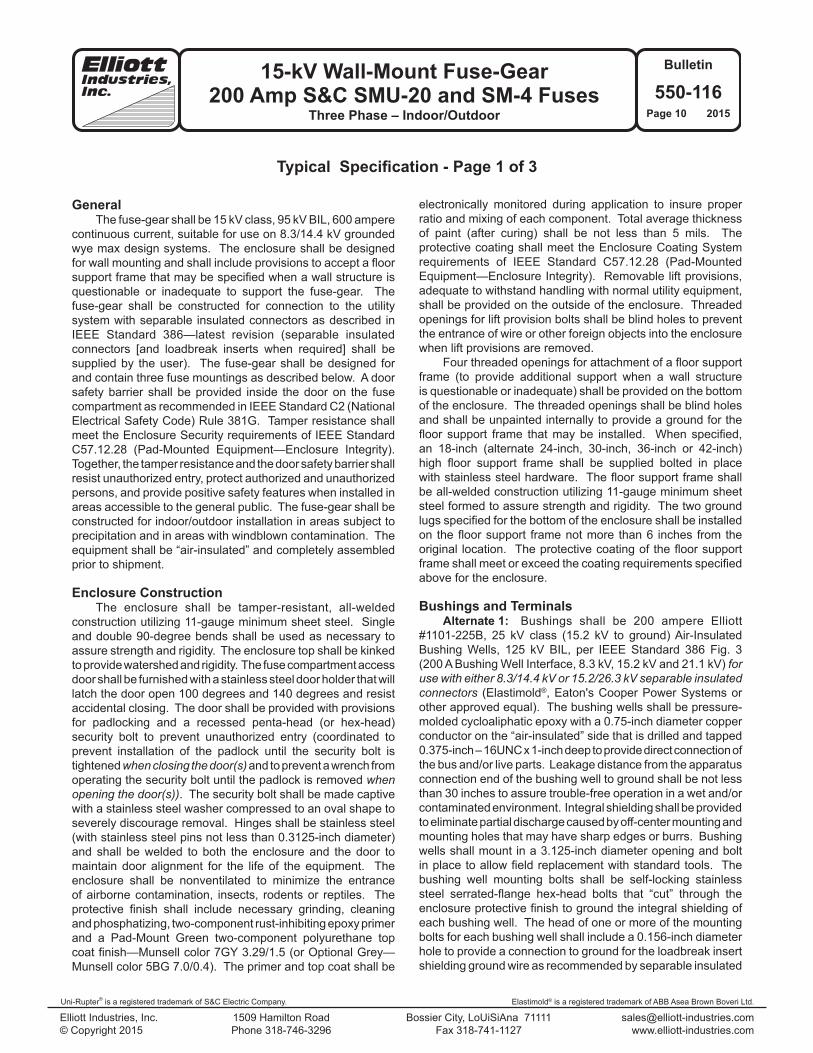
GeneralThe fuse-gear shall be 15 kV class, 95 kV BIL, 600 ampere
continuous current, suitable for use on 8.3/14.4 kV grounded wye max design systems. The enclosure shall be designed for wall mounting and shall include provisions to accept a floor support frame that may be specified when a wall structure is questionable or inadequate to support the fuse-gear. The fuse-gear shall be constructed for connection to the utility system with separable insulated connectors as described in IEEE Standard 386—latest revision (separable insulated connectors [and loadbreak inserts when required] shall be supplied by the user). The fuse-gear shall be designed for and contain three fuse mountings as described below. A door safety barrier shall be provided inside the door on the fuse compartment as recommended in IEEE Standard C2 (National Electrical Safety Code) Rule 381G. Tamper resistance shall meet the Enclosure Security requirements of IEEE Standard C57.12.28 (Pad-Mounted Equipment—Enclosure Integrity). Together, the tamper resistance and the door safety barrier shall resist unauthorized entry, protect authorized and unauthorized persons, and provide positive safety features when installed in areas accessible to the general public. The fuse-gear shall be constructed for indoor/outdoor installation in areas subject to precipitation and in areas with windblown contamination. The equipment shall be “air-insulated” and completely assembled prior to shipment.
Enclosure ConstructionThe enclosure shall be tamper-resistant, all-welded
construction utilizing 11-gauge minimum sheet steel. Single and double 90-degree bends shall be used as necessary to assure strength and rigidity. The enclosure top shall be kinked to provide watershed and rigidity. The fuse compartment access door shall be furnished with a stainless steel door holder that will latch the door open 100 degrees and 140 degrees and resist accidental closing. The door shall be provided with provisions for padlocking and a recessed penta-head (or hex-head) security bolt to prevent unauthorized entry (coordinated to prevent installation of the padlock until the security bolt is tightened when closing the door(s) and to prevent a wrench from operating the security bolt until the padlock is removed when opening the door(s)). The security bolt shall be made captive with a stainless steel washer compressed to an oval shape to severely discourage removal. Hinges shall be stainless steel (with stainless steel pins not less than 0.3125-inch diameter) and shall be welded to both the enclosure and the door to maintain door alignment for the life of the equipment. The enclosure shall be nonventilated to minimize the entrance of airborne contamination, insects, rodents or reptiles. The protective finish shall include necessary grinding, cleaning and phosphatizing, two-component rust-inhibiting epoxy primer and a Pad-Mount Green two-component polyurethane top coat finish—Munsell color 7GY 3.29/1.5 (or Optional Grey—Munsell color 5BG 7.0/0.4). The primer and top coat shall be
Typical Specification - Page 1 of 3
electronically monitored during application to insure proper ratio and mixing of each component. Total average thickness of paint (after curing) shall be not less than 5 mils. The protective coating shall meet the Enclosure Coating System requirements of IEEE Standard C57.12.28 (Pad-Mounted Equipment—Enclosure Integrity). Removable lift provisions, adequate to withstand handling with normal utility equipment, shall be provided on the outside of the enclosure. Threaded openings for lift provision bolts shall be blind holes to prevent the entrance of wire or other foreign objects into the enclosure when lift provisions are removed.
Four threaded openings for attachment of a floor support frame (to provide additional support when a wall structure is questionable or inadequate) shall be provided on the bottom of the enclosure. The threaded openings shall be blind holes and shall be unpainted internally to provide a ground for the floor support frame that may be installed. When specified, an 18-inch (alternate 24-inch, 30-inch, 36-inch or 42-inch) high floor support frame shall be supplied bolted in place with stainless steel hardware. The floor support frame shall be all-welded construction utilizing 11-gauge minimum sheet steel formed to assure strength and rigidity. The two ground lugs specified for the bottom of the enclosure shall be installed on the floor support frame not more than 6 inches from the original location. The protective coating of the floor support frame shall meet or exceed the coating requirements specified above for the enclosure.
Bushings and TerminalsAlternate 1: Bushings shall be 200 ampere Elliott
#1101-225B, 25 kV class (15.2 kV to ground) Air-Insulated Bushing Wells, 125 kV BIL, per IEEE Standard 386 Fig. 3 (200 A Bushing Well Interface, 8.3 kV, 15.2 kV and 21.1 kV) for use with either 8.3/14.4 kV or 15.2/26.3 kV separable insulated connectors (Elastimold®, Eaton's Cooper Power Systems or other approved equal). The bushing wells shall be pressure-molded cycloaliphatic epoxy with a 0.75-inch diameter copper conductor on the “air-insulated” side that is drilled and tapped 0.375-inch – 16UNC x 1-inch deep to provide direct connection of the bus and/or live parts. Leakage distance from the apparatus connection end of the bushing well to ground shall be not less than 30 inches to assure trouble-free operation in a wet and/or contaminated environment. Integral shielding shall be provided to eliminate partial discharge caused by off-center mounting and mounting holes that may have sharp edges or burrs. Bushing wells shall mount in a 3.125-inch diameter opening and bolt in place to allow field replacement with standard tools. The bushing well mounting bolts shall be self-locking stainless steel serrated-flange hex-head bolts that “cut” through the enclosure protective finish to ground the integral shielding of each bushing well. The head of one or more of the mounting bolts for each bushing well shall include a 0.156-inch diameter hole to provide a connection to ground for the loadbreak insert shielding ground wire as recommended by separable insulated

Elastimold® is a registered trademark of ABB Asea Brown Boveri Ltd.
15-kV Wall-Mount Fuse-Gear200 Amp S&C SMU-20 and SM-4 Fuses
Three Phase – Indoor/Outdoor
Elliott Industries, Inc. 1509 Hamilton Road Bossier City, LoUiSiAna 71111 [email protected] © Copyright 2015 Phone 318-746-3296 Fax 318-741-1127 www.elliott-industries.com
Bulletin
550-116Page 11 2015
Uni-Rupter® is a registered trademark of S&C Electric Company. Elastimold® is a registered trademark of ABB Asea Brown Boveri Ltd.
Typical Specification - Page 2 of 3
connector manufacturers. To assure adequate strength for apparatus support, the bushing well shall withstand a minimum cantilever loading of 600 pounds for five minutes without damage. The bushing well interface shall be free of all voids, holes and heat sinks to assure proper mating with separable insulated connectors. Each bushing well shall be tested in free air, mounted in a grounded steel plate not less than 10 inches x 10 inches, with a bushing well plug (Eaton's Cooper Power Systems #IBWP225 or equal) installed in the well interface to accurately simulate operating conditions (gas or liquid dielectric in the interface shall not be acceptable for this test). Each bushing well shall meet the requirements for 25 kV devices in accordance with IEEE Standard 386 (latest revision), including 100 percent production testing.
Alternate 2: Bushings shall be 600 ampere Elliott #1201-625B2, 25 kV class (15.2 kV to ground) Air-Insulated Bushings, 125 kV BIL, per IEEE Standard 386 Fig. 11 (600 A Deadbreak Interface No. 1, 8.3 kV and 15.2 kV) for use with either 8.3/14.4 kV or 15.2/26.3 kV separable insulated connectors (Elastimold®, Eaton's Cooper Power Systems or other approved equal). The bushings shall be pressure-molded cycloaliphatic epoxy with a 1.25-inch diameter tin-plated aluminum conductor on the “air-insulated” side that is drilled and tapped 0.625-inch – 11UNC x 1-inch deep to provide direct connection of the bus and/or live parts. Leakage distance from the apparatus connection end of the bushing to ground shall be not less than 30 inches to assure trouble-free operation in a wet and/or contaminated environment. Integral shielding shall be provided to eliminate partial discharge caused by off-center mounting and mounting holes that may have sharp edges or burrs. Bushings shall mount in a 3.125-inch diameter opening and bolt in place to allow field replacement with standard tools. The bushing mounting bolts shall be self-locking stainless steel serrated-flange hex-head bolts that “cut” through the enclosure protective finish to ground the integral shielding of each bushing. To assure adequate strength for apparatus support, the bushing shall withstand a minimum cantilever loading of 600 pounds for five minutes without damage. The bushing interface shall be free of all voids, holes and heat sinks to assure proper mating with separable insulated connectors. Each bushing shall be tested in free air, mounted in a grounded steel plate not less than 10 inches x 10 inches, with an insulated protective cap (Eaton's Cooper Power Systems #DPC625 or equal) installed on the interface to accurately simulate operating conditions (gas or liquid dielectric on the interface shall not be acceptable for this test). Each bushing shall meet the requirements for 25 kV devices in accordance with the test values of IEEE Standard 386 (latest revision), including 100 percent production testing.
Fuse MountingsFuse clips and/or fuse hinges shall be keyed to prevent
rotation and to maintain alignment. Positive pressure shall be assured by use of stainless steel fasteners and lock washers or
compression washers at all connection points. All connections shall provide direct contact of current-carrying parts and shall not depend on current transfer through fastener thread-to-thread contact. Fuses and their blown-fuse indicators shall be visible (when the fuse compartment door is open without removal of the clear-polycarbonate door safety barrier) to allow easy identification of blown fuses without de-energizing or removing the fuse from service. Electrical components shall be “air-insulated” and positioned to allow visual inspection of all internal connections and components without removing the clear-polycarbonate door safety barrier, de-energizing or removing the equipment from service. When Option G1 is specified, ground studs shall be provided for each terminal at the top of the fuse mounting. When Option G2 is specified, ground studs shall be provided for each terminal at the bottom of the fuse mounting.
Alternate 1: Fuse provisions without S&C Uni-Rupter® shall accommodate S&C Fuse-Unit End Fittings Type SML-20. Fuse-Unit End Fittings, when supplied, shall accept 200 amp (max) Type SMU-20 fuse units. (When this alternate is selected, loadbreak operations must be accomplished with loadbreak elbows). A Warning Sign, Elliott #7201-W2003-318, shall be provided inside the fuse compartment door to warn the operator to “Park the load side cable before installing or removing fuses.” A Danger Sign, Elliott #7203-D2003-313, shall be provided in a prominent location near the fuse clips to warn the operator “Do not remove fuse under load.”
Alternate 2: Fuse provisions with S&C Uni-Rupter® shall accommodate S&C Fuse-Unit End Fittings Type SML-20. Fuse-Unit End Fittings, when supplied, shall accept 200 amp (max) Type SMU-20 fuse units.
Alternate 3: Fuse provisions without S&C Uni-Rupter® shall accommodate S&C Fuse Holder Type SML-4Z. Fuse holders, when supplied, shall accept 200 amp (max) Type SM-4 fuse refills. (When this alternate is selected, loadbreak operations must be accomplished with loadbreak elbows). A Warning Sign, Elliott #7201-W2003-318, shall be provided inside the fuse compartment door to warn the operator to “Park the load side cable before installing or removing fuses.” A Danger Sign, Elliott #7203-D2003-313, shall be provided in a prominent location near the fuse clips to warn the operator “Do not remove fuse under load.”
Alternate 4: Fuse provisions with S&C Uni-Rupter® shall accommodate S&C Fuse Holder Type SML-4Z. Fuse holders, when supplied, shall accept 200 amp (max) Type SM-4 fuse refills.
BusBus shall be copper with all burrs and sharp corners
removed prior to installation. Positive pressure shall be assured by use of stainless steel fasteners and lock washers at all connection points. All connections shall provide direct contact of current-carrying parts and shall not depend on

15-kV Wall-Mount Fuse-Gear200 Amp S&C SMU-20 and SM-4 Fuses
Three Phase – Indoor/Outdoor
Elliott Industries, Inc. 1509 Hamilton Road Bossier City, LoUiSiAna 71111 [email protected] © Copyright 2015 Phone 318-746-3296 Fax 318-741-1127 www.elliott-industries.com
Bulletin
550-116Page 12 2015
Uni-Rupter® is a registered trademark of S&C Electric Company. Elastimold® is a registered trademark of ABB Asea Brown Boveri Ltd.
Typical Specification - Page 3 of 3
current transfer through fastener thread-to-thread contact. Electrical components shall be “air-insulated” and positioned to allow visual inspection of all internal connections and components without removing the clear-polycarbonate door safety barrier, de-energizing or removing the equipment from service.
BarriersPhase and ground barriers shall be provided to assure
correct phase-to-phase and phase-to-ground clearances for proper operation at rated voltage. These barriers shall be glass-reinforced polyester (NEMA GPO-3 class material) not less than 0.1875-inch thick.
A removable insulating barrier with a “DANGER – Keep Out! – Hazardous voltage” sign, Elliott #7203-D2003-309, shall be located inside the door(s) on the fuse compartment as recommended in Rule 381G of IEEE Standard C2 (National Electrical Safety Code). This door safety barrier shall be constructed of 0.25-inch clear-polycarbonate (Lexan or equal) and shall completely close the door opening and be provided with a nonconductive safety latch requiring a positive action to remove the barrier. Handles and other hardware extending through this door safety barrier shall be nonconductive material. Handles shall be keyed to prevent rotation for secure handling. Complete visual inspection of the internal components shall be possible without removing the door safety barrier.
Grounding ProvisionsFour high-conductivity bronze eyebolt-type ground
lugs, which accept #6 through #2/0 copper conductor, shall be installed on the enclosure (two on the exterior of the top and two on the exterior of the bottom). One 0.625-inch diameter copper grounding bar that bolts to both walls inside the enclosure shall be provided near the bottom of the door opening in a position easily accessible for attachment of grounding clamps. When grounding clamps are installed it shall be possible to close and lock the door.
Accessory EquipmentStainless steel parking stands shall be provided in the
quantity required to allow use of feed-thru bushings, parking bushings and grounding bushings. The parking stands shall be welded in place, in a position to allow the use of hot-line tools for installation of feed-thru bushings, etc. The parking stands shall be unpainted (except welds shall be painted) to provide a ground for feed-thru bushings and other devices that may be placed into the parking stands.
A corrosion proof nameplate with permanent thermal transfer printing shall be installed inside the compartment door. It shall be located at the top corner farthest from the enclosure when the door is open. The nameplate will provide Type of Equipment, Model Number, Amps Continuous, kV Maximum, BIL, Serial Number, Job Number, Date Manufactured and Weight of Equipment.
The enclosure shall be labeled in near proximity of the locking provisions with a pressure-sensitive vinyl label using letters not less than 0.375-inch nor more than 0.625-inch high. The label shall indicate the type of equipment behind the access (switch, fuses, bus, etc.).
PackagingEach enclosure shall be bolted to a solid-top wood pallet
(to prevent the forks of a forklift truck from entering the open bottom of the equipment) to prevent hidden damage. The equipment shall be wrapped with 0.125-inch thick polyethylene foam or other suitable material to minimize damage to the finish during shipment.
DrawingsWhen specified, drawings shall be furnished for each
fuse-gear that include:1) enclosure dimensions and location of components.2) proposed labels and location of labels.
If you do not find the design you need
PLEASE CONTACT
our REPRESENTATIVE or the FACTORY