14acx - acfurnaceparts.com manuals/14acx.pdfthe 14acx is a high efficiency residential...
TRANSCRIPT

Page 1 ©2006 Lennox Industries Inc.
Corp. 0638−L10
14ACXService Literature
14ACX SERIES UNITS
The 14ACX is a high efficiency residential split−system con-
densing unit, which features a scroll compressor and de-
signed for R−410A refrigerant. 14ACX units are available in
sizes ranging from 1−1/2 through 5 tons. The series is de-
signed for use with an expansion valve (TXV) or fixed orifice
system (RFC) in the indoor unit. This manual is divided into
sections which discuss the major components, refrigerant
system, charging procedure, maintenance and operation
sequence.
Information contained in this manual is intended for use by
qualified service technicians only. All specifications are sub-
ject to change.
IMPORTANTOperating pressures of this R−410A unit are higherthan pressures in R−22 units. Always use serviceequipment rated for R−410A.
WARNINGImproper installation, adjustment, alteration, serviceor maintenance can cause property damage, person-al injury or loss of life. Installation and service mustbe performed by a qualified installer or serviceagency.
WARNINGWarranty will be voided if covered equipment is re-moved from original installation site. Warranty willnot cover damage or defect resulting from:Flood, wind, lightning, or installation and operationin a corrosive atmosphere (chlorine, fluorine, salt,recycled waste water, urine, fertilizers, or other dam-aging chemicals).
TABLE OF CONTENTS
General Page 1. . . . . . . . . . . . . . . . . . . . . . . . . . .
Specifications / Electrical Data Page 2. . . . . . . .
I Application Page 3. . . . . . . . . . . . . . . . . . . . . . . .
II Unit Components Page 3. . . . . . . . . . . . . . . . . .
III Refrigeration System Page 6. . . . . . . . . . . . . .
IV Charging Page 7. . . . . . . . . . . . . . . . . . . . . . . .
VI Maintenance Page 13. . . . . . . . . . . . . . . . . . . . .
VII Wiring and Sequence of Operation Page 14.

Page 2
SPECIFICATIONS
GeneralD t
Model No. 14ACX−018 14ACX−024 14ACX−030 14ACX−036 14ACX−042 14ACX−048 14ACX−060Data Nominal Tonnage 1.5 2 2.5 3 3.5 4 5
Connections(sweat)
Liquid line o.d. − in. 3/8 3/8 3/8 3/8 3/8 3/8 3/8(sweat)
Suction line o.d. − in. 3/4 3/4 3/4 7/8 7/8 7/8 1-1/8
1 Refrigerant (R-410A) furnished 6 lbs. 12 oz. 7 lbs. 10 oz. 8 lbs. 0 oz. 8 lbs. 9 oz. 8 lbs. 10 oz. 10 lbs. 0 oz. 12 lbs. 0 oz.
OutdoorCoil
Net face areasq ft
Outer coil 13.22 13.22 16.33 16.33 16.33 21.00 22.00Coil - sq. ft.
Inner coil 12.60 12.60 15.71 15.71 15.71 20.25 21.33
Tube diameter − in. 5/16 5/16 5/16 5/16 5/16 5/16 5/16
Number of rows 2 2 2 2 2 2 2
Fins per inch 22 22 22 22 22 22 22
OutdoorFan
Diameter − in. 18 18 22 22 22 22 26Fan
Number of blades 4 4 4 4 4 4 4
Motor hp 1/5 1/5 1/6 1/6 1/4 1/4 1/3
Cfm 2400 2400 2900 2900 3500 3600 4400
Rpm 1100 1100 825 825 825 825 825
Watts 200 200 220 220 310 310 310
Shipping Data − lbs. 1 package 146 148 169 172 198 221 238
ELECTRICAL DATA
Line voltage data − 60 hz − 1ph 208/230V 208/230V 208/230V 208/230V 208/230V 208/230V 208/230V
2 Maximum overcurrent protection (amps) 20 30 30 30 40 50 60
3 Minimum circuit ampacity 12.3 17.9 17.2 18.7 24.1 29.0 34.8
Compressor Rated load amps 9.0 13.4 12.9 14.1 17.9 21.8 26.4p
Power factor .96 .97 .98 .98 .94 .95 .98
Locked rotor amps 48 58 64 77 112 117 134
CondenserFan Motor
Full load amps 1.0 1.0 1.1 1.1 1.7 1.7 1.8Fan Motor
Locked rotor amps 1.9 1.9 2.1 2.1 3.1 3.1 2.9
OPTIONAL ACcESSORIES − must be ordered extra
Compressor CrankcaseH t
93M05 � � � �pHeater 93M06 � Factory Factory
Compressor Hard Start Kit 10J42 �p
88M91 � � � � � �
Compressor Low Ambient Cut−Off 45F08 � � � � � � �
Compressor Sound Cover 69J03 � � � � � � �
Compressor Time−Off Control 47J27 � � � � � � �
Freezestat 3/8 in. tubing 93G35 � � � � � � �
5/8 in. tubing 50A93 � � � � � � �
Hail Guards 92M88 � �
45M56 � � �
92M90 �
27W35 �
Loss of Charge Switch Kit 84M23 � � � � � � �
Low Ambient Kit 34M72 � � � � � � �
Mounting Base 69J06 � �g
69J07 � � � � �
RefrigerantLine Sets
L15−41−20, L15−41−30,L15−41−40, L15−41−50
� � �
L15−65−30, L15−65−40,L15−65−50
� � �
Field Fabricate �
Time Delay Relay Kit 58M81 � � � � � � �
Unit Stand−Off Kit 94J45 � � � � � � �
NOTE � Extremes of operating range are plus 10% and minus 5% of line voltage.1 Refrigerant charge sufficient for 15 ft. length of refrigerant lines.2 HACR type circuit breaker or fuse.3 Refer to National or Canadian Electrical Code manual to determine wire, fuse and disconnect size requirements.

Page 3
I − APPLICATION
14ACX condensing units are available in 1−1/2, 2, 2 -1/2, 3,
3 -1/2, 4 and 5 ton capacities. All major components (indoor
blower and coil) must be matched according to Lennox rec-
ommendations for the compressor to be covered under war-
ranty. Refer to the Engineering Handbook for approved sys-
tem matchups.
II − UNIT COMPONENTSUnit components are illustrated in figure 1.
14ACX PARTS ARRANGEMENT
FIGURE 1
CAPACITOR
CONTACTOR
OUTDOOR FAN
COMPRESSOR
TIMEDOFF
CONTROL(OPTION)
HIGH PRESSURE SWITCH(hidden on liquid line)
A − Control Box (Figure 2)
14ACX units are not equipped with a 24V transformer. All
24 VAC controls are powered by the indoor unit. Refer to
wiring diagram.
Electrical openings are provided under the control box cov-
er. Field thermostat wiring is made to color-coded pigtail
connections.
ELECTROSTATIC DISCHARGE (ESD)
Precautions and Procedures
CAUTION
Electrostatic discharge can affect electronic com-ponents. Take precautions during unit installationand service to protect the unit’s electronic controls.Precautions will help to avoid control exposure toelectrostatic discharge by putting the unit, the con-trol and the technician at the same electrostatic po-tential. Neutralize electrostatic charge by touchinghand and all tools on an unpainted unit surface be-fore performing any service procedure.
FIGURE 2
DUAL CAPACITOR(C12)
COMPRESSORCONTACTOR
(K1)
CONTROL BOX
GROUNDINGLUG
TIMED OFFCONTROL.(OPTION)
1 − Compressor Contactor K1
DANGERShock Hazard
Remove all power at disconnectbefore removing access panel.Single phase 14ACX units usesingle-pole contactors. Potentialexists for electrical shock resultingin injury or death.Line voltage exists at all compo-nents (even when unit is not in op-eration).
The compressor is energized by a single−pole contactor lo-
cated in the control box. See figure 2. K1 is energized by the
indoor thermostat terminal Y1 (24V) when thermostat de-
mand is present.
2 − Dual Capacitor C12The compressor and fan in 14ACX series units use per-
manent split capacitor motors. The capacitor is located
inside the unit control box (see figure 2). A single �dual"
capacitor (C12) is used for both the fan motor and the
compressor (see unit wiring diagram). The fan side and
the compressor side of the capacitor have different MFD
ratings. See side of capacitor for ratings.
3 − Timed Off Control TOC (option)The time delay is electrically connected between thermostat
terminal Y and the compressor contactor. Between cycles,
the compressor contactor is delayed for 5 minutes ± 2 min-
utes but may last as long as 8 minutes. At the end of the
delay, the compressor is allowed to energize. When thermo-
stat demand is satisfied, the time delay opens the circuit to
the compressor contactor coil and the compressor is de−en-
ergized.

Page 4
B − Compressor
The scroll compressor design is simple, efficient and requires
few moving parts. A cutaway diagram of the scroll compressor
is shown in figure 3. The scrolls are located in the top of the
compressor can and the motor is located just below. The oil lev-
el is immediately below the motor.
FIGURE 3
SCROLL COMPRESSOR
DISCHARGE
SUCTION
The scroll is a simple compression concept centered around
the unique spiral shape of the scroll and its inherent properties.
Figure 4 shows the basic scroll form. Two identical scrolls are
mated together forming concentric spiral shapes (figure 5). One
scroll remains stationary, while the other is allowed to "orbit" (fig-
ure 6). Note that the orbiting scroll does not rotate or turn but
merely orbits the stationary scroll.
The counterclockwise orbiting scroll draws gas into the outer
crescent shaped gas pocket created by the two scrolls (figure 6
− 1). The centrifugal action of the orbiting scroll seals off the
flanks of the scrolls (figure 6 − 2). As the orbiting motion contin-
ues, the gas is forced toward the center of the scroll and the gas
pocket becomes compressed (figure 6 − 3). When the com-
pressed gas reaches the center, it is discharged vertically into a
chamber and discharge port in the top of the compressor (figure
5). The discharge pressure forcing down on the top scroll helps
seal off the upper and lower edges (tips) of the scrolls (figure 5).
During a single orbit, several pockets of gas are compressed
simultaneously providing smooth continuous compression.
The scroll compressor is tolerant to the effects of liquid return. If
liquid enters the scrolls, the orbiting scroll is allowed to separate
from the stationary scroll. The liquid is worked toward the center
of the scroll and is discharged. If the compressor is replaced,
conventional Lennox cleanup practices must be used.
Due to its efficiency, the scroll compressor is capable of draw-
ing a much deeper vacuum than reciprocating compressors.
Deep vacuum operation can cause internal fusite arcing
resulting in damaged internal parts and will result in com-
pressor failure. Never use a scroll compressor for eva-
cuating or �pumping−down" the system. This type of dam-
age can be detected and will result in denial of warranty
claims.
The scroll compressor is quieter than a reciprocating com-
pressor, however, the two compressors have much different
sound characteristics. The sounds made by a scroll compres-
sor do not affect system reliability, performance, or indicate
damage.
NOTE − During operation, the head of a scroll compressor may
be hot since it is in constant contact with discharge gas.
FIGURE 4
SCROLL FORM
FIGURE 5
STATIONARY SCROLL
ORBITING SCROLL
DISCHARGE
SUCTION
CROSS−SECTION OF SCROLLS
TIPS SEALED BYDISCHARGE PRESSURE
DISCHARGEPRESSURE

Page 5
1 2
3 4
SUCTION
SUCTION
ORBITING SCROLL
STATIONARY SCROLL
SUCTION SUCTION
DISCHARGE
SUCTIONINTERMEDIATE PRESSURE
GAS
CRESCENTSHAPED
GAS POCKET
HIGH PRESSURE GAS
FLANKS SEALED
BY CENTRIFUGALFORCE
MOVEMENT OF ORBIT
FIGURE 6
C − Condenser Fan Motor
All units use single−phase PSC fan motors which require a run
capacitor. In all units, the condenser fan is controlled by
the compressor contactor.
ELECTRICAL DATA tables in this manual show specifi-
cations for condenser fans used in 14ACX ’s.
Access to the condenser fan motor on all units is gained
by removing the seven screws securing the fan assem-
bly. See figure 7. The condenser fan motor is removed
from the fan guard by removing the four nuts found on the
top panel. Drip loops (to prevent moisture from entering
the motor) should be used in wiring when servicing mo-
tor. See figure 8 if condenser fan motor replacement is
necessary.
Make sure all power is disconnected beforebeginning electrical service procedures.
DANGER
FAN
CONDENSER FAN MOTORAND COMPRESSOR ACCESS
Remove (7) screws
REMOVE (7) SCREWSSECURING FAN GUARD.
REMOVE FAN GUARD/FANASSEMBLY.
MOTOR
FAN GUARD
WIRING
FIGURE 7
RACEWAY
Remove (4) nuts
RACEWAY
MOTOR WIRESLOOP WIRES AS SHOWN
CONTROL BOX
ALIGN FAN HUB FLUSH WITH END OF SHAFT
FIGURE 8
Page 6
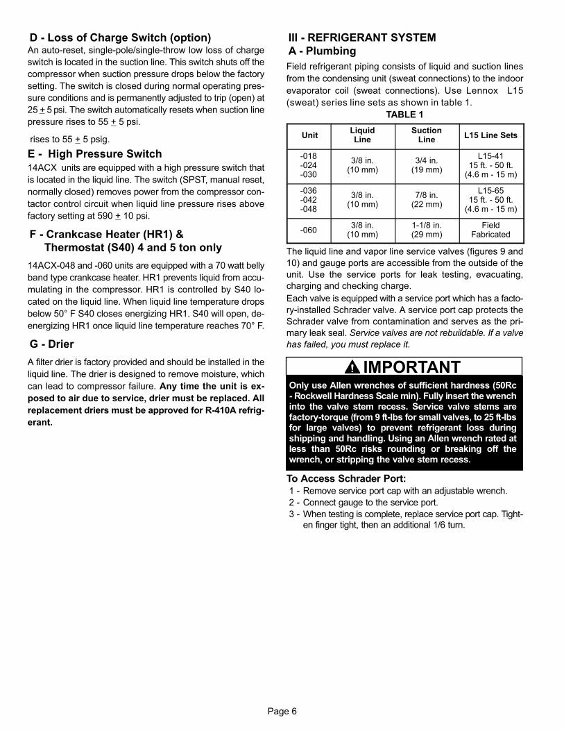
D − Loss of Charge Switch (option)An auto-reset, single-pole/single-throw low loss of charge
switch is located in the suction line. This switch shuts off the
compressor when suction pressure drops below the factory
setting. The switch is closed during normal operating pres-
sure conditions and is permanently adjusted to trip (open) at
25 + 5 psi. The switch automatically resets when suction line
pressure rises to 55 + 5 psi.
rises to 55 + 5 psig.
E − High Pressure Switch
14ACX units are equipped with a high pressure switch that
is located in the liquid line. The switch (SPST, manual reset,
normally closed) removes power from the compressor con-
tactor control circuit when liquid line pressure rises above
factory setting at 590 + 10 psi.
F − Crankcase Heater (HR1) &
Thermostat (S40) 4 and 5 ton only
14ACX−048 and −060 units are equipped with a 70 watt belly
band type crankcase heater. HR1 prevents liquid from accu-
mulating in the compressor. HR1 is controlled by S40 lo-
cated on the liquid line. When liquid line temperature drops
below 50° F S40 closes energizing HR1. S40 will open, de−
energizing HR1 once liquid line temperature reaches 70° F.
G − Drier
A filter drier is factory provided and should be installed in the
liquid line. The drier is designed to remove moisture, which
can lead to compressor failure. Any time the unit is ex-
posed to air due to service, drier must be replaced. All
replacement driers must be approved for R−410A refrig-
erant.
III − REFRIGERANT SYSTEM
A − Plumbing
Field refrigerant piping consists of liquid and suction lines
from the condensing unit (sweat connections) to the indoor
evaporator coil (sweat connections). Use Lennox L15
(sweat) series line sets as shown in table 1.
TABLE 1
UnitLiquidLine
SuctionLine
L15 Line Sets
−018−024−030
3/8 in.(10 mm)
3/4 in.(19 mm)
L15−4115 ft. − 50 ft.
(4.6 m − 15 m)
−036−042−048
3/8 in.(10 mm)
7/8 in.(22 mm)
L15−6515 ft. − 50 ft.
(4.6 m − 15 m)
−0603/8 in.
(10 mm)1−1/8 in.(29 mm)
FieldFabricated
The liquid line and vapor line service valves (figures 9 and
10) and gauge ports are accessible from the outside of the
unit. Use the service ports for leak testing, evacuating,
charging and checking charge.
Each valve is equipped with a service port which has a facto-
ry−installed Schrader valve. A service port cap protects the
Schrader valve from contamination and serves as the pri-
mary leak seal. Service valves are not rebuildable. If a valve
has failed, you must replace it.
Only use Allen wrenches of sufficient hardness (50Rc− Rockwell Hardness Scale min). Fully insert the wrenchinto the valve stem recess. Service valve stems arefactory−torque (from 9 ft−lbs for small valves, to 25 ft−lbsfor large valves) to prevent refrigerant loss duringshipping and handling. Using an Allen wrench rated atless than 50Rc risks rounding or breaking off thewrench, or stripping the valve stem recess.
IMPORTANT
To Access Schrader Port:
1 − Remove service port cap with an adjustable wrench.
2 − Connect gauge to the service port.
3 − When testing is complete, replace service port cap. Tight-en finger tight, then an additional 1/6 turn.
Page 7
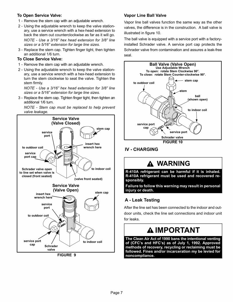
To Open Service Valve:
1 − Remove the stem cap with an adjustable wrench.
2 − Using the adjustable wrench to keep the valve station-ary, use a service wrench with a hex−head extension toback the stem out counterclockwise as far as it will go.
NOTE − Use a 3/16" hex head extension for 3/8" linesizes or a 5/16" extension for large line sizes.
3 − Replace the stem cap. Tighten finger tight, then tightenan additional 1/6 turn.
To Close Service Valve:
1 − Remove the stem cap with an adjustable wrench.
2 − Using the adjustable wrench to keep the valve station-ary, use a service wrench with a hex−head extension toturn the stem clockwise to seat the valve. Tighten thestem firmly.
NOTE − Use a 3/16" hex head extension for 3/8" linesizes or a 5/16" extension for large line sizes.
3 − Replace the stem cap. Tighten finger tight, then tighten anadditional 1/6 turn.
NOTE − Stem cap must be replaced to help preventvalve leakage.
Service Valve(Valve Closed)
Schrader valve opento line set when valve is
closed (front seated)
serviceport
serviceport cap
stem cap
insert hexwrench here
(valve front seated)
to outdoor coil
to indoor coil
Service Valve(Valve Open)
Schradervalve
serviceport
service portcap
insert hexwrench here
to indoor coil
to outdoor coil
stem cap
FIGURE 9
Vapor Line Ball Valve
Vapor line ball valves function the same way as the other
valves, the difference is in the construction. A ball valve is
illustrated in figure 10.
The ball valve is equipped with a service port with a factory−
installed Schrader valve. A service port cap protects the
Schrader valve from contamination and assures a leak−free
seal.
Ball Valve (Valve Open)
FIGURE 10
Schrader valve
service port
service portcap
stem cap
stem
Use Adjustable WrenchTo open: rotate Stem Clockwise 90°.
To close: rotate Stem Counter-clockwise 90°.
ball(shown open)
to outdoor coil
to indoor coil
IV − CHARGING
WARNINGR−410A refrigerant can be harmful if it is inhaled.R−410A refrigerant must be used and recovered re-sponsibly.
Failure to follow this warning may result in personalinjury or death.
A − Leak Testing
After the line set has been connected to the indoor and out-
door units, check the line set connections and indoor unit
for leaks.
IMPORTANTThe Clean Air Act of 1990 bans the intentional ventingof (CFC’s and HFC’s) as of July 1, 1992. Approvedmethods of recovery, recycling or reclaiming must befollowed. Fines and/or incarceration my be levied fornoncompliance.

Page 8
WARNINGDanger of explosion!
When using a high pressure gas suchas dry nitrogen to pressurize a refriger-ant or air conditioning system, use aregulator that can control the pressuredown to 1 or 2 psig (6.9 to 13.8 kPa).
WARNINGFire, Explosion and Personal SafetyHazard.Failure to follow this warning couldresult in damage, personal injury ordeath.Never use oxygen to pressurize orpurge refrigeration lines. Oxygen,when exposed to a spark or openflame, can cause damage by fireand / or an explosion, that can re-sult in personal injury or death.
Using an Electronic Leak Detector
1 − Connect a cylinder of R−410A to the center port of the
manifold gauge set. Connect manifold gauge to service
valve port.
2 − With both manifold valves closed, open the valve on the
R−410A cylinder.
3 − Open the high pressure side of the manifold to allow the
R−410A into the line set and indoor unit. Weigh in a trace
amount of R−410A. [A trace amount is a maximum of 2
ounces (57 g) or 3 pounds (31 kPa) pressure.] Close the
valve on the R−410A cylinder and the valve on the high
pressure side of the manifold gauge set. Disconnect the
R−410A cylinder.
4 − Connect a cylinder of nitrogen with a pressure regulat-
ing valve to the center port of the manifold gauge set.
5 − Connect the manifold gauge set high pressure hose to
the vapor valve service port. (Normally, the high pres-
sure hose is connected to the liquid line port; however,
connecting it to the vapor port better protects the man-
ifold gauge set from high pressure damage.)
6 − Adjust the nitrogen pressure to 150 psig (1034 kPa).
Open the valve on the high side of the manifold gauge
set which will pressurize line set and indoor unit.
7 − After a few minutes, open a refrigerant port to ensure
the refrigerant you added is adequate to be detected.
(Amounts of refrigerant will vary with line lengths.)
Check all joints for leaks. Purge nitrogen and R−410A
mixture. Correct any leaks and recheck.
B − Evacuating
Evacuating the system of noncondensables is critical for
proper operation of the unit. Noncondensables are defined
as any gas that will not condense under temperatures and
pressures present during operation of an air conditioning
system. Noncondensables and water vapor combine with
refrigerant to produce substances that corrode copper pip-
ing and compressor parts.
NOTE − This evacuation process is adequate for a new
installation with clean and dry lines. If excessive mois-
ture is present, the evacuation process may be required
more than once.
IMPORTANTUse a thermocouple or thermistor electronic vacuumgauge that is calibrated in microns. Use an instrumentthat reads from 50 microns to at least 20,000 microns.
1 − Connect manifold gauge set to the service valve ports :
� low pressure gauge to vapor line service valve
� high pressure gauge to liquid line service valve
2 − Connect micron gauge.
3 − Connect the vacuum pump (with vacuum gauge) to the
center port of the manifold gauge set.
4 − Open both manifold valves and start the vacuum
pump.
5 − Evacuate the line set and indoor unit to an absolute
pressure of 23,000 microns (29.01 inches of mercury).
During the early stages of evacuation, it is desirable to
close the manifold gauge valve at least once to deter-
mine if there is a rapid rise in absolute pressure. A rap-
id rise in pressure indicates a relatively large leak. If this
occurs, repeat the leak testing procedure.
NOTE − The term absolute pressure means the total
actual pressure within a given volume or system, above
the absolute zero of pressure. Absolute pressure in a
vacuum is equal to atmospheric pressure minus vacu-
um pressure.
6 − When the absolute pressure reaches 23,000 microns
(29.01 inches of mercury), close the manifold gauge
valves, turn off the vacuum pump and disconnect the
manifold gauge center port hose from vacuum pump.
Attach the manifold center port hose to a nitrogen cylin-
der with pressure regulator set to 150 psig (1034 kPa)
and purge the air from the hose with nitrogen. Open the
manifold gauge valves to break the vacuum in the line
set and indoor unit. Close the manifold gauge valves.

Page 9
CAUTIONDanger of Equipment Damage.Avoid deep vacuum operation. Do not use compres-sors to evacuate a system.Extremely low vacuums can cause internal arcing andcompressor failure.Damage caused by deep vacuum operation will voidwarranty.
7 − Shut off the nitrogen cylinder and remove the manifold
gauge hose from the cylinder. Open the manifold gauge
valves to release the nitrogen from the line set and in-
door unit.
8 − Reconnect the manifold gauge to the vacuum pump,
turn the pump on, and continue to evacuate the line set
and indoor unit until the absolute pressure does not rise
above 500 microns (29.9 inches of mercury) within a
20−minute period after shutting off the vacuum pump
and closing the manifold gauge valves.
9 − When the absolute pressure requirement above has
been met, disconnect the manifold hose from the vacu-
um pump and connect it to an upright cylinder of R−410A
refrigerant. Open the manifold gauge valves to break the
vacuum from 1 to 2 psig positive pressure in the line set
and indoor unit. Close manifold gauge valves and shut
off the R−410A cylinder and remove the manifold gauge
set.
C − Charging
This system uses R−410A refrigerant which operates atmuch higher pressures than R−22. The provided liquid linefilter drier is approved for use with R−410A. Do not replace itwith components designed for use with R−22. This unit isNOT approved for use with coils which use capillary tubesas a refrigerant metering device.
Factory ChargeUnits are factory-charged with the amount of R−410A refrig-erant indicated on the unit rating plate. This charge is basedon a matching indoor coil and outdoor coil with 15 ft. (4.6 m)line set. For varying lengths of line set, refer to table 2 for re-frigerant charge adjustment.
TABLE 2
Refrigerant Charge per Line Set Lengths
Liquid LineSet Diameter
Oz. per 5 ft. (g per 1.5 m) adjustfrom 15 ft. (4.6 m) line set*
3/8 in. (9.5 mm) 3 ounce per 5 ft. (85 g per 1.5 m)
NOTE − *If line length is greater than 15 ft. (4.6 m), add this amount. Ifline length is less than 15 ft. (4.6 m), subtract this amount.
IMPORTANTMineral oils are not compatible with R−410A. If oilmust be added, it must be a polyol ester oil.
NOTE − The compressor is charged with sufficient polyol es-
ter oil. If oil must be added to the compressor in the field, use
Mobil EAL� Arctic 22CC or ICI EMKARATE� RL32CF.
Pre−charge Airflow Check of Temperature Dropacross Evaporator Coil (Delta−T)NOTE − Be sure that filters and indoor and outdoor coils are
clean before testing
Measure the entering air dry bulb (DB) and wet bulb (WB)temperatures at the indoor coil. Find Delta−T in table 3. Mea-sure evaporator coil’s leaving air DB and subtract that valuefrom the entering air DB. The measured difference shouldbe within + 3ºF (1.8ºC) of table value. If Delta−T is too low,decrease the indoor fan speed (refer to indoor unit for infor-mation). If the Delta−T is high, increase the indoor fan speed.Repeat charging procedure and Delta−T (air flow adjust-ment) procedure until both are correct.
Example:
Assume entering air DB − 72, WB − 64, leaving DB − 53.
Delta−T should be 15 (per table); delta across coil is 19 (72
minus 53) which is 4ºF higher than table value; therefore, in-
crease fan speed.
Checking ChargeThe outdoor unit should be charged during warm weather.However, applications arise in which charging must occur inthe colder months. The method of charging is determined bythe unit’s refrigerant metering device and the outdoorambient temperature.
TABLE 3
80 24 24 24 23 23 22 22 22 20 19 18 17 16 15
Dry bulb 78 23 23 23 22 22 21 21 20 19 18 17 16 15 14Dry bulbtemperature 76 22 22 22 21 21 20 19 19 18 17 16 15 14 13temperature
of air enteringi d il
74 21 21 21 20 19 19 18 17 16 16 15 14 13 12gindoor coil 72 20 20 19 18 17 17 16 15 15 14 13 12 11 10
70 19 19 18 18 17 17 16 15 15 14 13 12 11 10
57 58 59 60 61 62 63 64 65 66 67 68 69 70
Wet bulb temperature of air entering indoor coil

Page 10
WHEN TO CHARGE?
� Warm weather best
� Can charge in colder weather
CHARGE METHOD? Determine by:
� Metering device type
� Outdoor ambient temperature
REQUIREMENTS:
� Sufficient heat load in structure
� Indoor temperature between 70-80ºF (21−26ºC)
� Manifold gauge set connected to unit
� Thermometers:− to measure outdoor ambient temperature− to measure liquid line temperature− to measure vapor line temperature
TXV RFC
APPROACH ORSUBCOOLING
WEIGH-IN SUPERHEAT
Whichmeteringdevice?
Below 65ºF(18ºC)?
Above 40ºF(4ºC)?
Above 65ºF(18ºC)?
START: Determine how refrigerant is metered
FIGURE 11. When to charge, method to use, conditions & equipment required
IMPORTANTBefore attempting to charge any system, confirm proper airflow across the in-door coil. Airflow over the indoor coil can be determined by measuring the stat-ic pressure drop across the coil and comparing it with the factory table pro-vided in the indoor coil installation instructions.
If value is greater thanshown, add refrigerant;if less than shown,remove refrigerant.
ABOVE Outdoor
ambient 40ºF(4ºC)?
START: Measure outdoor ambient temperature
BELOW
� Check Liquid and Vapor line pressures
� Compare unit pressures with NormalOperating Pressures table 4, page 12.
(Table 4 is a general guide. Expect minor pressuresvariations. Significant differences may mean improp-er charge or other system problem.)
� Use SUPERHEAT to correctly charge unitor to verify the charge is correct.
NOTE − Do not at-tempt to charge sys-tem where a dash ap-pears, system couldbe overcharged. Su-perheat is taken at va-por line service port.Vapor line superheatmust never be lessthan 5ºF at the vaporline service port.
USE WEIGH-IN METHOD
Weigh-in or remove refriger-ant based upon line length
SHº (Superheat) Values (+/−5ºF)
Wet Bulb (air entering indoor coil)
ºF* 50 52 54 56 58 60 62 64 66 68 70 72 74 76
40 15 18 20 23 26 29 32 34 38 41 43 46 48 51
45 13 16 18 21 24 27 30 33 36 39 41 44 46 49
50 11 14 16 19 22 25 28 31 34 37 39 42 44 47
55 9 12 14 17 20 23 27 30 33 36 38 40 42 44
60 7 10 12 15 18 21 24 27 30 33 35 38 40 43
65 - 6 10 13 16 19 21 24 27 30 33 36 38 41
70 - - 7 10 13 16 19 21 24 27 30 33 36 39
75 - - - 6 9 12 15 18 21 24 28 31 34 37
80 - - - - 5 8 12 15 18 21 25 28 31 35
85 - - - - - - 8 11 15 19 22 26 30 33
90 - - - - - - 5 9 13 16 20 24 27 31
95 - - - - - - - 6 10 14 18 22 25 29
100 - - - - - - - - 8 12 16 21 24 28
105 - - - - - - - - 5 9 13 17 22 26
110 - - - - - - - - - 6 11 15 20 25
115 - - - - - - - - - - 8 14 18 24
* Dry−bulb temperature (ºF) of entering outdoor ambient air.
If refrigerant added or
removed, retest to
confirm that unit is
properly charged
SUPERHEAT METHOD� Set thermostat to call for heat (must have a
cooling load between 70-80ºF (21−26ºC)
� Connect gauge set
� When heat demand is satisfied, setthermostat to call for cooling
� Allow temperatures and pressures tostabilize
� Record vapor line pressure; use value todetermine saturation temperature (table 5 on page 12) SATº =
� Record vapor line temperature VAPº =
� Subtract to determine superheat (SHº):
� VAPº − SATº = SHº
� Record the wet bulb temperature (airentering indoor coil) WB =
� Record outdoor ambient temperature
� Compare results with table
FIGURE 12. Charging RFC units with SUPERHEAT Method

Page 11
ºF (ºC)* −018 −024 −030 −036 −042 −048 −060
65 (18) 3 (1.7) 5 (2.8) 4 (2.2) 5 (2.8) 6 (3.3) 7 (3.9) 8 (4.4)
75 (24) 5 (2.8) 6 (3.3) 5 (2.8) 5 (2.8) 8 (4.4) 8 (4.4) 9 (5.0)
85 (29) 6 (3.3) 6 (3.3) 6 (3.3) 6 (3.3) 8 (4.4) 8 (4.4) 9 (5.0)
95 (35) 6 (3.3) 7 (3.9) 6 (3.3) 6 (3.3) 8 (4.4) 8 (4.4) 9 (5.0)
105 (41) 6 (3.3) 6 (3.3) 6 (3.3) 5 (2.8) 8 (4.4) 8 (4.4) 9 (5.0)
115 (45) 6 (3.3) 6 (3.3) 6 (3.3) 6 (3.3) 8 (4.4) 9 (5.0) 9 (5.0)
*Temperature of air entering outdoor coil
APPROACH METHOD� Set thermostat to call for heat (must have a
cooling load between 70-80ºF (21−26ºC)
� Connect gauge set
� When heat demand is satisfied, setthermostat to call for cooling
� Allow temperatures and pressures tostabilize
� Record outdoor ambient temperature AMBº =
� Record line temp. LIQº =
� Subtract to determine approach (APPº):
� LIQº − AMBº = APPº
� Compare results with table
If value is greater than shown (high
approach), add refrigerant; if less than
shown (liquid temp to close to ambient
temp low approach, remove refrigerant
DO NOT CHARGE UNIT
(Results of charging at lowtemperatures not reliable)
ABOVE
START: Measure outdoor ambient temperature
BELOW
� Check Liquid and Vapor line pressures
� Compare unit pressures with NormalOperating Pressures table 4, page 12.
(Table 4 is a general guide. Expect minor pressuresvariations. Significant differences may mean improp-er charge or other system problem.)
� Use APPROACH to correctly charge unit orto verify the charge is correct.
USE WEIGH-IN METHOD
Weigh-in or remove refriger-ant based upon line length
APPº (Approach) Values(F:+/−1.0°; [C: +/−0.5°])
Above or below 65ºF
(18ºC)?
If refrigerant added or
removed, retest to
confirm that unit is
properly charged
FIGURE 13 Charging TXV units with Approach Method
DO NOT CHARGE UNIT
(Results of charging at lowtemperatures not reliable)
ABOVE
START: Measure outdoor ambient temperature
BELOW
� Check Liquid and Vapor line pressures
� Compare unit pressures with NormalOperating Pressures table 4, page 12.
(Table 4 is a general guide. Expect minor pressuresvariations. Significant differences may mean improp-er charge or other system problem.)
� Use SUBCOOLING to correctly charge unitor to verify the charge is correct.
USE WEIGH-IN METHOD
Weigh-in or remove refriger-ant based upon line length
SUBCOOLING METHOD� Set thermostat to call for heat (must have a
cooling load between 70-80ºF (21−26ºC)
� Connect gauge set
� Measure outdoor ambient temperature
� When heat demand is satisfied, setthermostat to call for cooling
� Allow temperatures and pressures tostabilize [NOTE − IF NECESSARY, blockoutdoor coil to maintain 325 − 375 psig]
� Record line temp. LIQº =
� Record liquid line pressure; use value todetermine saturation temperature (table 5 on page 12) SATº =
� Subtract to determine subcooling (SCº):
� SATº − LIQº = SCº
� Compare results with table
ºF (ºC)* −018 −024 −030 −036 −042 −048 −060
65 (18) 10 (5.6) 10 (5.6) 10 (5.6) 11 (6.1) 10 (5.6) 8 (4.4) 8 (4.4)
75 (24) 6 (3.3) 8 (4.4) 8 (4.4) 11 (6.1) 7 (3.9) 8 (4.4) 7 (3.9)
85 (29) 6 (3.3) 8 (4.4) 7 (3.9) 11 (6.1) 7 (3.9) 8 (4.4) 8 (4.4)
95 (35) 6 (3.3) 8 (4.4) 7 (3.9) 10 (5.6) 7 (3.9) 8 (4.4) 7 (3.9)
105 (41) 6 (3.3) 8 (4.4) 7 (3.9) 10 (5.6) 7 (3.9) 8 (4.4) 7 (3.9)
115 (45) 6 (3.3) 8 (4.4) 6 (3.3) 9 (5.0) 7 (3.9) 7 (3.9) 6 (3.3)
*Temperature of air entering outdoor coil
SCº (Subcooling) Values (F:+/−1.0°; [C: +/−0.5°])
Above or below 65ºF
(18ºC)?
If refrigerant added or
removed, verify
charge using the
approach method
BLOCK OUTDOOR COIL[sometimes necessary with lower temperatures]Use cardboard or plastic sheet to restrict theairflow through the outdoor coil to achieve pres-sures from 325−375 psig (2240−2585 kPa).Higher pressures are needed to check charge.Block equal sections of air intake panels andmove coverings sideways until the liquid pres-sure is in the above noted ranges.
If value is greater thanshown, remove refrigerant; ifless than shown, addrefrigerant.
FIGURE 14 Charging TXV units with SUBCOOLING Method
Page 12
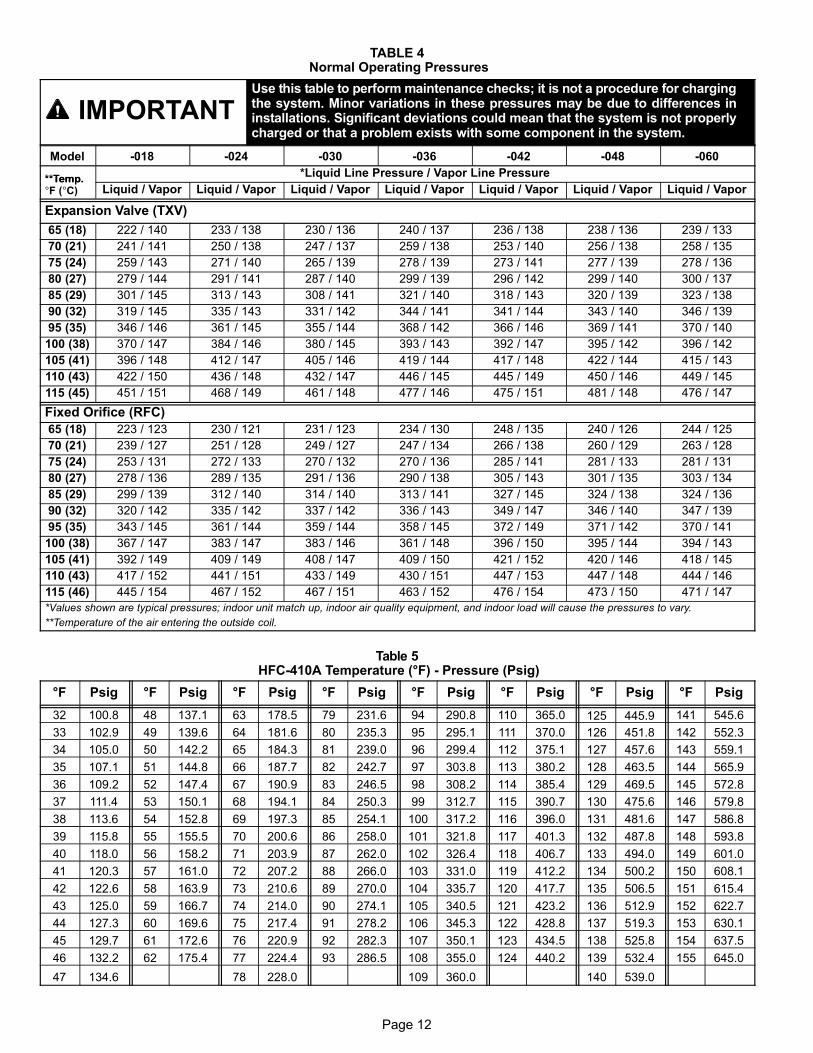
TABLE 4 Normal Operating Pressures
IMPORTANTUse this table to perform maintenance checks; it is not a procedure for chargingthe system. Minor variations in these pressures may be due to differences ininstallations. Significant deviations could mean that the system is not properlycharged or that a problem exists with some component in the system.
Model −018 −024 −030 −036 −042 −048 −060
**Temp.*Liquid Line Pressure / Vapor Line Pressure
**Temp.�F (�C) Liquid / Vapor Liquid / Vapor Liquid / Vapor Liquid / Vapor Liquid / Vapor Liquid / Vapor Liquid / Vapor
Expansion Valve (TXV)
65 (18) 222 / 140 233 / 138 230 / 136 240 / 137 236 / 138 238 / 136 239 / 133
70 (21) 241 / 141 250 / 138 247 / 137 259 / 138 253 / 140 256 / 138 258 / 135
75 (24) 259 / 143 271 / 140 265 / 139 278 / 139 273 / 141 277 / 139 278 / 136
80 (27) 279 / 144 291 / 141 287 / 140 299 / 139 296 / 142 299 / 140 300 / 137
85 (29) 301 / 145 313 / 143 308 / 141 321 / 140 318 / 143 320 / 139 323 / 138
90 (32) 319 / 145 335 / 143 331 / 142 344 / 141 341 / 144 343 / 140 346 / 139
95 (35) 346 / 146 361 / 145 355 / 144 368 / 142 366 / 146 369 / 141 370 / 140
100 (38) 370 / 147 384 / 146 380 / 145 393 / 143 392 / 147 395 / 142 396 / 142
105 (41) 396 / 148 412 / 147 405 / 146 419 / 144 417 / 148 422 / 144 415 / 143
110 (43) 422 / 150 436 / 148 432 / 147 446 / 145 445 / 149 450 / 146 449 / 145
115 (45) 451 / 151 468 / 149 461 / 148 477 / 146 475 / 151 481 / 148 476 / 147
Fixed Orifice (RFC)
65 (18) 223 / 123 230 / 121 231 / 123 234 / 130 248 / 135 240 / 126 244 / 125
70 (21) 239 / 127 251 / 128 249 / 127 247 / 134 266 / 138 260 / 129 263 / 128
75 (24) 253 / 131 272 / 133 270 / 132 270 / 136 285 / 141 281 / 133 281 / 131
80 (27) 278 / 136 289 / 135 291 / 136 290 / 138 305 / 143 301 / 135 303 / 134
85 (29) 299 / 139 312 / 140 314 / 140 313 / 141 327 / 145 324 / 138 324 / 136
90 (32) 320 / 142 335 / 142 337 / 142 336 / 143 349 / 147 346 / 140 347 / 139
95 (35) 343 / 145 361 / 144 359 / 144 358 / 145 372 / 149 371 / 142 370 / 141
100 (38) 367 / 147 383 / 147 383 / 146 361 / 148 396 / 150 395 / 144 394 / 143
105 (41) 392 / 149 409 / 149 408 / 147 409 / 150 421 / 152 420 / 146 418 / 145
110 (43) 417 / 152 441 / 151 433 / 149 430 / 151 447 / 153 447 / 148 444 / 146
115 (46) 445 / 154 467 / 152 467 / 151 463 / 152 476 / 154 473 / 150 471 / 147
*Values shown are typical pressures; indoor unit match up, indoor air quality equipment, and indoor load will cause the pressures to vary.
**Temperature of the air entering the outside coil.
Table 5 HFC−410A Temperature (°F) − Pressure (Psig)
°F Psig °F Psig °F Psig °F Psig °F Psig °F Psig °F Psig °F Psig
32 100.8 48 137.1 63 178.5 79 231.6 94 290.8 110 365.0 125 445.9 141 545.6
33 102.9 49 139.6 64 181.6 80 235.3 95 295.1 111 370.0 126 451.8 142 552.3
34 105.0 50 142.2 65 184.3 81 239.0 96 299.4 112 375.1 127 457.6 143 559.1
35 107.1 51 144.8 66 187.7 82 242.7 97 303.8 113 380.2 128 463.5 144 565.9
36 109.2 52 147.4 67 190.9 83 246.5 98 308.2 114 385.4 129 469.5 145 572.8
37 111.4 53 150.1 68 194.1 84 250.3 99 312.7 115 390.7 130 475.6 146 579.8
38 113.6 54 152.8 69 197.3 85 254.1 100 317.2 116 396.0 131 481.6 147 586.8
39 115.8 55 155.5 70 200.6 86 258.0 101 321.8 117 401.3 132 487.8 148 593.8
40 118.0 56 158.2 71 203.9 87 262.0 102 326.4 118 406.7 133 494.0 149 601.0
41 120.3 57 161.0 72 207.2 88 266.0 103 331.0 119 412.2 134 500.2 150 608.1
42 122.6 58 163.9 73 210.6 89 270.0 104 335.7 120 417.7 135 506.5 151 615.4
43 125.0 59 166.7 74 214.0 90 274.1 105 340.5 121 423.2 136 512.9 152 622.7
44 127.3 60 169.6 75 217.4 91 278.2 106 345.3 122 428.8 137 519.3 153 630.1
45 129.7 61 172.6 76 220.9 92 282.3 107 350.1 123 434.5 138 525.8 154 637.5
46 132.2 62 175.4 77 224.4 93 286.5 108 355.0 124 440.2 139 532.4 155 645.0
47 134.6 78 228.0 109 360.0 140 539.0

Page 13
V − MAINTENANCE
WARNINGElectric shock hazard. Can cause injuryor death. Before attempting to performany service or maintenance, turn theelectrical power to unit OFF at discon-nect switch(es). Unit may have multiplepower supplies.
Maintenance and service must be performed by a qualified
installer or service agency. At the beginning of each cooling
season, the system should be checked as follows:
1.Make sure power is off before cleaning. Clean and inspect
outdoor coil. The coil may be flushed with a water hose.
The outdoor coil is protected by an inner mesh screen
and a wire cage (see figure 15). If debris has collected
between the mesh screen and the coil and cannot be
dislodged by spraying unpressurized water from inside
coil surface to the outside, the mesh may be removed by
first removing the top of the unit which will allow for re-
moval of the wire cage.
Then, using pliers to grip the head of the push pins, pull
straight out to extract the push pins along one side of the
coil. If necessary, remove the push pins along the back
of the unit; it is usually unnecessary to fully remove the
inner mesh screen.
Drape the mesh screen back and wash the coil. When
all the debris has been removed from the coil, reinstall
the mesh screen by positioning it in its original position
and reinserting the push pin. No tool is required to push
the pin back into the same slot in the fins.
If the push pin is loose and tends not to stay in place,
brush the fins with a fin brush (22 fins/in). Line up the
push pin a couple fins to the right or left of the original
hole and re−insert the pin.
2.Outdoor fan motor is prelubricated and sealed. No further
lubrication is needed.
3.Visually inspect connecting lines and coils for evidence of
oil leaks.
4.Check wiring for loose connections.
5.Check for correct voltage at unit (unit operating).
6.Check amp−draw outdoor fan motor.
Unit nameplate _________ Actual ____________ .
NOTE − If owner reports insufficient cooling, the unit shouldbe gauged and refrigerant charge checked. See refrigerantcharging section.
9 pins used on−048 and −060; 6pins all others
PUSH PIN
MESH SCREEN
Figure 15
ÎÎÎÎÎÎÎÎÎÎÎÎÎÎÎÎÎÎÎÎÎÎÎÎÎÎÎÎÎÎÎÎÎÎÎÎÎÎÎÎÎÎÎÎÎÎÎÎÎÎÎÎÎÎÎÎÎÎÎÎÎÎÎÎÎÎÎÎÎÎÎÎÎÎÎÎÎÎÎÎÎÎÎÎÎÎÎÎÎÎÎÎÎÎÎÎÎÎ
Indoor Coil1.Clean coil, if necessary.
2.Check connecting lines and coils for signs of oil leaks.
3.Check the condensate pan line and clean if necessary.
Indoor Unit1.Clean or change filters.
2.Adjust blower speed for cooling. The pressure drop over thecoil should be measured to determine the correct blowerCFM. Refer to the unit information service manual forpressure drop tables and procedure.
3.Check all wiring for loose connections
4.Check for correct voltage at unit (blower operating).
5.Check amp−draw on blower motor.
Unit nameplate_________ Actual ____________.

Page 14
VI − 14ACX UNIT WIRING DIAGRAM AND SEQUENCE OF OPERATION
NOTE− The thermostat used may be electromechanical or electronic.
NOTE− Transformer in indoor unit supplies power (24 VAC) to the thermostat and outdoor unit controls.
COOLING:
1− Cooling demand initiates at Y1 in the thermostat.
2− 24VAC from indoor unit (Y1) energizes the TOC timed off control (if used) which energizes contactor K1
(provided S4 high pressure switch is closed).
3− K1-1 N.O. closes, energizing compressor (B1) and outdoor fan motor (B4).
4− Compressor (B1) and outdoor fan motor (B4) begin immediate operation..
END OF COOLING DEMAND:
5− Cooling demand is satisfied. Terminal Y1 is de-energized .
6− Compressor contactor K1 is de-energized.
7− K1-1 opens and compressor (B1) and outdoor fan motor (B4) are de-energized and stop immediately.