1472. closed-form solution of curved beam model of elastic
TRANSCRIPT

© JVE INTERNATIONAL LTD. JOURNAL OF VIBROENGINEERING. DEC 2014, VOLUME 16, ISSUE 8. ISSN 1392-8716 3951
1472. Closed-form solution of curved beam model of elastic mechanical wheel
Bo Li1, Youqun Zhao2, Liguo Zang3 College of Energy and Power Engineering, Nanjing University of Aeronautics and Astronautics, Nanjing, 210016, China 1Corresponding author E-mail: [email protected], [email protected], [email protected] (Received 4 October 2014; received in revised form 21 November 2014; accepted 2 December 2014)
Abstract. Based on the Timoshenko curved beam theory, a novel and feasible closed-form solution was proposed to deal with the internal mechanics characteristics of mechanical elastic wheel (MEW). With the Laplace transformation and boundary conditions, the governing differential equations was reduced to a single equation in regard to the rotation angle of curved beam, so as to reveal the relationship among the radial deformation, the tangential deformation and the curved angle. Furthermore, by adopting the Frobenius theory and the Green function, six normalized solutions of equations, the general solution and the free vibration of system equations were obtained. In the end, structure mechanics and vibration modal experiments were carried out and the results show that the analytical model is applicable for the experimental results. Keywords: mechanical elastic wheel, Timoshenko curved beam, Laplace transformation, Green function.
1. Introduction
The properties of tires are of great influence on the vehicle driving performance, which supports vehicle weight, transfers driving force and braking force, and ensures enough adhesion force between the wheel and the ground. In addition, tires should meet requirements for safety, durability and comfort, and safety [1]. However, as statistics show, 70 %-80 % of the traffic accidents in superhighway are caused by tire blow-out. In order to promote the development of the modern automobile industry, mechanical elastic wheels emerged as required [2-4].
There is a flood of theoretical and computational literature on the mechanics analysis of pneumatic tire and circular structure [5-13]. Despite the curved beam model is widely used in various structures, but rarely used in the analysis of the tire model [14-16]. On one side, Kung proposed a flexible boundary loop model based on the radial and circumferential springs, and then verified it by using complicated finite element method [17]. Huang and Soedel studied the influence of coriolis acceleration of dynamic elastic boundary ring, and compared it with static ring model [18, 19]. On the other side, Kindt used the three-dimensional ring model to analyze structure-bearing noise, and proved that this model was suitable for the condition of 300 Hz [20]. However, all those ring models on the Euler-Bernoulli Beam assumption overlook the factors of shear deformation.
In this work, the curved beam model of MEW was proposed based on Timoshenko curved beam theory to pridict deformations, forces and vibration modal of mechanical elastic wheel on plane rigid ground. The relationship among three parameters: the radial deformation, the tangential deformation and curved deformation, free vibration and the closed-form solution of system equations were obtained by using the Frobenius theory and the Green function experiments were finally carried out to check the feasibility and efficiency of the proposed model.
2. Characteristics of MEW
MEW is mainly consisted of one hub, hinges and elastic ring, as shown in Fig. 1. The external of elastic ring is parceled by rubber tread, and which is connected to the hub by hinges with the same angle along the circumferential direction. The forces and deformation of pneumatic wheel

1472. CLOSED-FORM SOLUTION OF CURVED BEAM MODEL OF ELASTIC MECHANICAL WHEEL. BO LI, YOUQUN ZHAO, LIGUO ZANG
3952 © JVE INTERNATIONAL LTD. JOURNAL OF VIBROENGINEERING. DEC 2014, VOLUME 16, ISSUE 8. ISSN 1392-8716
in load case are shown in Fig. 2, meanwhile whose circumferential part are under stress, just the force on the bottom is small. The hinges of MEW can only sustain tension, and have zero modulus in compression, so the deformation and couple of the elastic ring is large,which is shown in Fig. 3, and the rest of elastic ring along the circumferential direction almost remains the same for the high stiffness of hinges assumed as rigid-body. Therefore, the curved beam of elastic ring is the key part of MEW.
Fig. 1. Structure of MEW
Loaded wheelUnloaded wheel
Road
Fig. 2. Forces and deformation of pneumatic wheel
Fig. 3. Forces and deformation of MEW
3. Curved beam analysis
3.1. Governing equation and boundary conditions
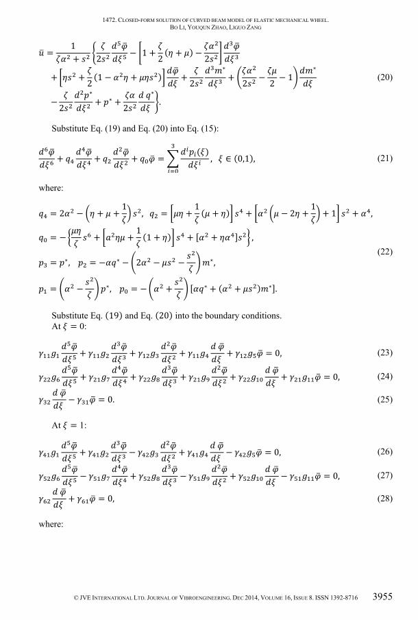
According to the mechanics model of curved beam in Fig. 4, the setting-up of the Timoshenko curved beam model is as below:
1472. CLOSED-FORM SOLUTION OF CURVED BEAM MODEL OF ELASTIC MECHANICAL WHEEL. BO LI, YOUQUN ZHAO, LIGUO ZANG
© JVE INTERNATIONAL LTD. JOURNAL OF VIBROENGINEERING. DEC 2014, VOLUME 16, ISSUE 8. ISSN 1392-8716 3953
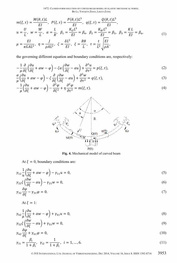
( , ) = ( , ) , ( , ) = ( , ) , ( , ) = ( , ) ,= , = , = , = = , = = , = = ,= , = , = , = , = , (1)
the governing different equation and boundary conditions are, respectively:
− 1 + − − − + = ( , ), (2)∂∂ + − − ∂∂ ∂∂ − + ∂∂ = ( , ), (3)− 1 ∂∂ + − − ∂∂ + ∂∂ = ( , ). (4)
Fig. 4. Mechanical model of curved beam
At = 0, boundary conditions are: 1 ∂∂ + − − = 0, (5)∂∂ − − = 0, (6)∂∂ − = 0. (7)
At = 1: 1 ∂∂ + − + = 0, (8)∂∂ − + = 0, (9)∂∂ + = 0, (10)= 1 + , = 11 + , = 1, … , 6. (11)

1472. CLOSED-FORM SOLUTION OF CURVED BEAM MODEL OF ELASTIC MECHANICAL WHEEL. BO LI, YOUQUN ZHAO, LIGUO ZANG
3954 © JVE INTERNATIONAL LTD. JOURNAL OF VIBROENGINEERING. DEC 2014, VOLUME 16, ISSUE 8. ISSN 1392-8716
( ) and ( ) are tangential and radial deformation, respectively, ( ) is curving angle, ( ), ( ) and ( ) are vertical load, axial load and bending moment, respectively, , , , , and are Young modulus, shear modulus, correction factor, area inertia moment, mass inertia
moment and sectional area, respectively, , and are density, the length of the beam and radius, respectively, , and are radial, tangential and rotation constraining force, respectively:
( , 0) = ( ), ∂ ( , 0)∂ = ( ), (12)
where, ( ) and ( ) are initial functions. By taking the Laplace transformation, and the governing differential equations are as:
− 1 + − − − + = ∗( , ), (13)+ − − − + = ∗( , ), (14)− 1 + − − + = ∗( , ), (15)
where:
( , ) = ( , ) , ( , ) = ( , ) ,( , ) = ( , ) , ̅( , ) = ( , ) ,( , ) = ( , ) , ( , ) = ( , ) ,∗( , ) = ( , ) + [ ( ) + ( )], ∗( , ) = ̅( , ) + [ ( ) + ( )],∗( , ) = ( , ) + [ ( ) + ( )]. (16)
Substitute Eq. (15) into Eq. (13):
= 1+ − + − ∗ + + ∗ . (17)
Multiply / and ( + )/ by the derivatives of Eq. (14) and Eq. (17) respectively, then add them together:
+ − 1 − = − + − ∗ + ∗ − ∗. (18)
Multiply ( / − 1) by Eq. (15), and then subtract it from Eq. (18):
= 2 1 + 1 − ( + ) + 1 − + + 1 ∗ − − 1 ∗ − 1 ∗ + 1 ∗ . (19)
Substitute Eq. (19) into Eq. (17):
1472. CLOSED-FORM SOLUTION OF CURVED BEAM MODEL OF ELASTIC MECHANICAL WHEEL. BO LI, YOUQUN ZHAO, LIGUO ZANG
© JVE INTERNATIONAL LTD. JOURNAL OF VIBROENGINEERING. DEC 2014, VOLUME 16, ISSUE 8. ISSN 1392-8716 3955
= 1+ 2 − 1 + 2 ( + ) − 2 + + 2 (1 − + ) + 2 ∗ + 2 − 2 − 1 ∗ − 2 ∗ + ∗ + 2 ∗ . (20)
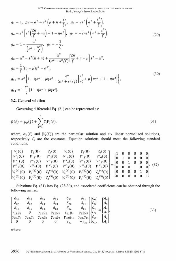
Substitute Eq. (19) and Eq. (20) into Eq. (15):
+ + + = ( ) , ∈ (0,1), (21)
where:
= 2 − + + 1 , = + 1 ( + ) + − 2 + 1 + 1 + ,= − + + 1 (1 + ) + [ + ] ,= ∗, = − ∗ − 2 − − ∗,= − ∗, = − + [ ∗ + ( + ) ∗].
(22)
Substitute Eq. (19) and Eq. (20) into the boundary conditions. At = 0:
+ + + + = 0, (23)+ + + + + = 0, (24) − = 0. (25)
At = 1:
+ − + − = 0, (26)− + − + − = 0, (27) + = 0, (28)
where:
1472. CLOSED-FORM SOLUTION OF CURVED BEAM MODEL OF ELASTIC MECHANICAL WHEEL. BO LI, YOUQUN ZHAO, LIGUO ZANG
3956 © JVE INTERNATIONAL LTD. JOURNAL OF VIBROENGINEERING. DEC 2014, VOLUME 16, ISSUE 8. ISSN 1392-8716
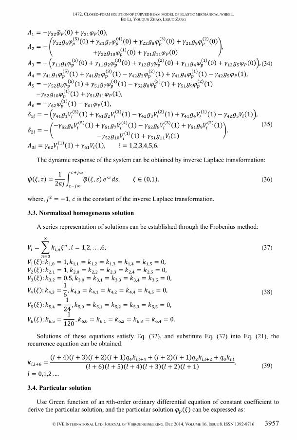
= 1, = − + + 2 , = 2 + ,= 2 + + 1 − , = −2 + ,= 1 − + , = − 1 , (29)
= − ( + ) + ( + ⁄ ) 2 + + − ,= 1 [( + ) − ],= 1 − + − ( + ⁄ ) 2 + + 1 − ,= − [1 − + ].
(30)
3.2. General solution
Governing differential Eq. (21) can be represented as:
( ) = ( ) + ( ), (31)
where, ( ) and { ( )} are the particular solution and six linear normalized solutions, respectively, are the constants. Equation solutions should meet the following standard conditions: (0) (0) (0) (0) (0) (0)(0) (0) (0) (0) (0) (0)(0) (0) (0) (0) (0) (0)(0) (0) (0) (0) (0) (0)( )(0) ( )(0) ( )(0) ( )(0) ( )(0) ( )(0)( )(0) ( )(0) ( )(0) ( )(0) ( )(0) ( )(0)
=1 0 0 0 0 00 1 0 0 0 00 0 1 0 0 00 0 0 1 0 00 0 0 0 1 00 0 0 0 0 1
. (32)
Substitute Eq. (31) into Eq. (23-30), and associated coefficients can be obtained through the following matrix:
00 0 0 0 −= , (33)
where:
1472. CLOSED-FORM SOLUTION OF CURVED BEAM MODEL OF ELASTIC MECHANICAL WHEEL. BO LI, YOUQUN ZHAO, LIGUO ZANG
© JVE INTERNATIONAL LTD. JOURNAL OF VIBROENGINEERING. DEC 2014, VOLUME 16, ISSUE 8. ISSN 1392-8716 3957
= − (0) + (0), = − ( )(0) + ( )(0) + ( )(0) + ( )(0)+ ( )(0) + (0) , = − ( )(0) + ( )(0) + ( )(0) + ( )(0) + (0) , = ( )(1) + ( )(1) − ( )(1) + ( )(1) − (1), = − ( )(1) + ( )(1) − ( )(1) + ( )(1) − ( )(1) + (1), (34)
= − ( )(1) − (1), = − ( )(1) + ( )(1) − ( )(1) + ( )(1) − (1) , = − − ( )(1) + ( )(1) − ( )(1) + ( )(1)− ( )(1) + (1) , = ( )(1) + (1), = 1,2,3,4,5,6. (35)
The dynamic response of the system can be obtained by inverse Laplace transformation:
( , ) = 12 ( , ) , ∈ (0,1), (36)
where, = −1, is the constant of the inverse Laplace transformation.
3.3. Normalized homogeneous solution
A series representation of solutions can be established through the Frobenius method:
= , , = 1,2, . . . ,6, (37) ( ): , = 1, , = , = , = , = , = 0, ( ): , = 1, , = , = , = , = , = 0, ( ): , = 0.5, , = , = , = , = , = 0, ( ): , = 16 , , = , = , = , = , = 0, ( ): , = 124 , , = , = , = , = , = 0, ( ): , = 1120 , , = , = , = , = , = 0. (38)
Solutions of these equations satisfy Eq. (32), and substitute Eq. (37) into Eq. (21), the recurrence equation can be obtained:
, = ( + 4)( + 3)( + 2)( + 1) , + ( + 2)( + 1) , + ,( + 6)( + 5)( + 4)( + 3)( + 2)( + 1) , = 0,1,2 …. (39)
3.4. Particular solution
Use Green function of an th-order ordinary differential equation of constant coefficient to derive the particular solution, and the particular solution ( ) can be expressed as:

1472. CLOSED-FORM SOLUTION OF CURVED BEAM MODEL OF ELASTIC MECHANICAL WHEEL. BO LI, YOUQUN ZHAO, LIGUO ZANG
3958 © JVE INTERNATIONAL LTD. JOURNAL OF VIBROENGINEERING. DEC 2014, VOLUME 16, ISSUE 8. ISSN 1392-8716
( ) = ( ) ( − ) , (40)
where: ( ) = ( ) ( ), ( ) = ( ) ( ), ( ) = [ ( ) − ( )] ( ), ( ) = [ ( ) − ( )] ( ), (41)
where ( ) is Heaviside function.
3.5. Free vibration
Considering free vibration on the system, (Laplace transformation parameter) is replaced by , that means = , and = ⁄ . Because of Eq. (33) are zero, then the frequence
equation of the curved beam should be written as:
00 0 0 0 −= 0. (42)
4. Experimental verification
4.1. Structural mechanics verification
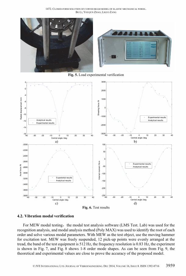
In order to verify the accuracy of the curved beam model of MEW, the vertical loading experiments were carried out in Fig. 5. The material and geometric parameters of MEW are shown in Table1. The vertical deflection is set as = 15 mm, and the measurement range of curved beam is −40° ≤ ≤ 40°. The contrastive analysis between analytical results and experimental results in regard to the radial displacement, the shear force, the axial force and the internal couple is performed in Fig. 6. It can be perceived that the consistency between experiment results and analytic results is good.
In Fig. 6(a), the greatest radial deformation emerges in the center of elastic ring, and rapidly decreases along with the growth of central angle, up to the ends of the curved beam near the stretching hinge shown in Fig. 3. The changes of internal shear force in curved beam is shown in Fig. 6(b), the maximum shear force is near the centre of curved beam, where should be the contact edges of elastic beam and ground, because the change of bending angle is larger. The change rate of shear force near the ends of curved beam shows obvious ups and downs, which is mainly because of the large bending deformation near the contact part between the curved beam and rigid hinges. The results in Fig. 6(c) and Fig. 6(d) show the maximum axial force and internal moment are located in the center of curved beam, and the rate of change near the ends of curved beam still shows obvious fluctuation.
Table 1. Wheel property Material parameters Geometrical parameters
(GPa) (GPa) (mm) ℎ (mm) (mm) (mm) 180 75 420 25 180 15
1472. CLOSED-FORM SOLUTION OF CURVED BEAM MODEL OF ELASTIC MECHANICAL WHEEL. BO LI, YOUQUN ZHAO, LIGUO ZANG
© JVE INTERNATIONAL LTD. JOURNAL OF VIBROENGINEERING. DEC 2014, VOLUME 16, ISSUE 8. ISSN 1392-8716 3959
Fig. 5. Load experimental verification
a)
b)
c)
d)
Fig. 6. Test results
4.2. Vibration modal verification
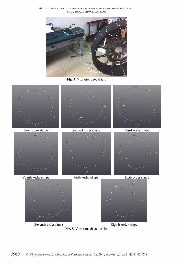
For MEW modal testing,the modal test analysis software (LMS Test. Lab) was used for the recognition analysis, and modal analysis method (Poly MAX) was used to identify the root of each order and solve various modal parameters. With MEW as the test object, use the moving hammer for excitation test. MEW was freely suspended, 12 pick-up points were evenly arranged at the tread, the band of the test equipment is 512 Hz, the frequency resolution is 0.83 Hz, the experiment is shown in Fig. 7, and Fig. 8 shows 1-8 order mode shapes. As can be seen from Fig. 9, the theoretical and experimental values are close to prove the accuracy of the proposed model.
-40 -30 -20 -10 0 10 20 30 40-16
-14
-12
-10
-8
-6
-4
-2
0
Central angle /deg
Rad
ial d
ispl
acem
ent /
mm
Analytical resultsExperimental results
-40 -30 -20 -10 0 10 20 30 40-3000
-2000
-1000
0
1000
2000
3000
Central angle /deg
She
arin
g fo
rce
/N
Experimental resultsAnalytical results
-40 -30 -20 -10 0 10 20 30 40-3800
-3600
-3400
-3200
-3000
-2800
-2600
-2400
-2200
-2000
Central angle /deg
Axi
al fo
rce
/N
Experiental resultsAnalytical results
-40 -30 -20 -10 0 10 20 30 40-250
-200
-150
-100
-50
0
50
100
Central angle /deg
Inte
rnal
mom
ent /
N.m
Experimental resultsAnalytical results
1472. CLOSED-FORM SOLUTION OF CURVED BEAM MODEL OF ELASTIC MECHANICAL WHEEL. BO LI, YOUQUN ZHAO, LIGUO ZANG
3960 © JVE INTERNATIONAL LTD. JOURNAL OF VIBROENGINEERING. DEC 2014, VOLUME 16, ISSUE 8. ISSN 1392-8716
Fig. 7. Vibration modal test
First-order shape Second-order shape
Third-order shape
Fourth-order shape Fifth-order shape
Sixth-order shape
Seventh-order shape
Eighth-order shape
Fig. 8. Vibration shape results

1472. CLOSED-FORM SOLUTION OF CURVED BEAM MODEL OF ELASTIC MECHANICAL WHEEL. BO LI, YOUQUN ZHAO, LIGUO ZANG
© JVE INTERNATIONAL LTD. JOURNAL OF VIBROENGINEERING. DEC 2014, VOLUME 16, ISSUE 8. ISSN 1392-8716 3961
Fig. 9. Vibration frequency comparison of the experiment and theory
5. Conclusions
1) With the condition of vertical load on rigid ground, as well as the different bearing characteristics between pneumatic tire and MEW considered, the curved beam model is developed based on the Timoshenko curved beam theory.
2) According to the force, displacement and elastic boundary conditions of curved beam, the normalized fundamental solutions and special solution of governing differential equations are obtained by Frobenius method and Green function, respectively. The relationship among radial displacement, tangential displacement and curving angle is also revealed.
3) Through load experiments and vibration modal experiments on MEW the proposed model was validated, and which proves effective.
Acknowledgements
Project (NHA13002) supported by the Major Exploration Project of the General Armaments Department of China. Project (CXLX13_145) supported by Funding of Jiangsu Innovation Program for Graduate Education and the Fundamental Research Funds for the Central Universities of China.
References
[1] Ahn Changsun, Peng Huei, Tseng H. Eric Robust estimation of road friction coefficient using lateral and longitudinal vehicle dynamics. Vehicle System Dynamics, Vol. 50, Issue 6, 2012, p. 961-985.
[2] Bras B., Cobert A. Life-cycle environmental impact of michelin Tweel® tire for passenger vehicles. SAE International Journal of Passenger Cars-Mechanical Systems, Vol. 4, Issue 1, 2011, p. 32-43.
[3] Laske R. F., Losey R. A., Gobinath T., et al. Self-Supporting Pneumatic Tire. U.S. Patent Application, 12/955, 097, 2010.
[4] Cardile D., Viola N., Chiesa S., et al. Applied design methodology for lunar rover elastic wheel. Acta Astronautica, Vol. 81, Issue 1, 2012, p. 1-11.
[5] Nguyen V. N., Matsuo T., Inaba S., Koumoto T. Experimental analysis of vertical soil reaction and soil stress distribution under off-road tires. Journal of Terramechanics, Vol. 45, 2008, p. 25-44.
[6] Fervers C. W. Improved FEM simulation model for tire-soil interaction. Journal of Terramechanics, Vol. 41, 2004, p. 87-100.
[7] Carman K. Prediction of soil compaction under pneumatic tires using fuzzy logic approach. Journal of Terramechanics, Vol. 45, 2008, p. 103-108.
[8] Nakashima H., Oida A. Algorithm and implementation of soil-tire contact analysis code based on dynamic FE-DE method. Journal of Terramechanics, Vol. 41, 2004, p. 127-137.
[9] Pacejka H. B., Sharp R. S. Shear force development by pneumatic tyres in steady state conditions: a review of modeling aspects. Vehicle System Dynamics, Vol. 20, 1991, p. 121-176.
[10] Sjahdanulirwan M., Yang Q. Prediction of tyre-road friction with an inverted-boat shaped stress distribution. Vehicle System Dynamics, Vol. 24, 1995, p. 145-161.
[11] Lin S. M., Lee S. Y. Closed-form solutions for dynamic analysis of extensional circular Timoshenko beams. International Journal of Solids and Structures, Vol. 38, 2001, p. 227-240.

1472. CLOSED-FORM SOLUTION OF CURVED BEAM MODEL OF ELASTIC MECHANICAL WHEEL. BO LI, YOUQUN ZHAO, LIGUO ZANG
3962 © JVE INTERNATIONAL LTD. JOURNAL OF VIBROENGINEERING. DEC 2014, VOLUME 16, ISSUE 8. ISSN 1392-8716
[12] Soedel W., Prasad M. G. Calculation of natural frequencies and modes of tires in road contact by utilizing eigenvalues of the axisymmetric non-contacting tire. Journal of Sound and Vibration, Vol. 70, 1980, p. 573-584.
[13] Narasimhan A., Ziegert J., Thompson L. Effects of material properties on static load-deflection and vibration of a non-pneumatic tire during high-speed rolling. SAE International Journal of Passenger Cars Mechanical Systems, Vol. 4, Issue 1, 2011, p. 59-72.
[14] Lin K. C., Hsieh C. M. The closed form general solutions of 2-D curved laminated beams of variable curvatures. Composite Structures, Vol. 79, 2007, p. 608-618.
[15] Amir Gasmia, Paul F. Josepha, Timothy B. Rhyne, et al. Closed-form solution of a shear deformable, extensional ring in contact between two rigid surfaces. International Journal of Solids and Structures, Vol. 48, 2011, p. 843-853.
[16] Rajasekaran S. Analysis of curved beams using a new differential transformation based curved beam element. Meccanica, Vol. 49, Issue 4, 2014, p. 863-886.
[17] Kung L. E., Soedel W., Yang T. Y. Free vibration of a pneumatic tire-wheel unit using a ring on an elastic foundation and a finite element model. Journal of Sound and Vibration, Vol. 107, 1986, p. 181-194.
[18] Huang S. C., Soedel W. Effects of Coriolis acceleration on the free and forced in-plane vibration of rotating rings on elastic foundation. Journal of Sound and Vibration, Vol. 115, 1987, p. 253-274.
[19] Huang S. C., Su C. K. In-plane dynamics of tires on the road based on an experimentally verified rolling ring model. Vehicle System Dynamics, Vol. 21, 1992, p. 247-267.
[20] Kindt P., Sas P., Desmet W. Development and validation of a three-dimensional ring-based structural tyre model. Journal of Sound and Vibration, Vol. 326, Issue 3, 2009, p. 852-869.
Bo Li received the B.S. and M.S. degrees in Mechanical Engineering from Yantai University, China, in 2008 and 2011, respectively. Now he is a Ph.D. student with School of Energy and Power Engineering, NUAA, Nanjing, China. His research interests include tyre dynamic, vibration analysis and vehicle dynamic simulation and control.
Youqun Zhao received the B.S., M.S. and Ph.D. degrees from Jilin University, China, in 1990, 1993 and 1998, respectively. Presently he is a professor in Vehicle Engineering of NUAA, he is particularly interested in tyre dynamic, vibration analysis, electric car, vehicle dynamic simulation and control.
Liguo Zang received the Master’s degree in Shandong University of Technology, Zibo, China, in 2011. Now he is a Ph.D. student with School of Energy and Power Engineering, NUAA, Nanjing, China. His research interests include tyre dynamic, electromagnetic compatibility.