14.5 polygonal weirs-introduction -...
TRANSCRIPT

Hydraulics Prof. B.S. Thandaveswara
Indian Institute of Technology Madras
14.5 Polygonal weirs-Introduction
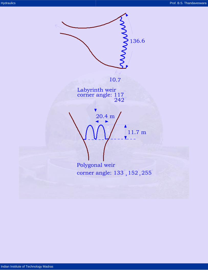
Weirs and spillways with a polygonal discontinuous center line can be designed in
various manner. Figure 1 shows some of the examples such as square intake towers,
labyrinth weirs, duck-bill overfalls.
97.5 m
30.0 m
Stilling basinDuck-bill overfallcorner angle: 90
148.0 m
14.4 m
Labyrinth weircorner angle: 45.6
314.4
Hydraulics Prof. B.S. Thandaveswara
Indian Institute of Technology Madras
11.7 m
20.4 m
Labyrinth weircorner angle: 117
242
Polygonal weircorner angle: 133 152 255, ,

Hydraulics Prof. B.S. Thandaveswara
Indian Institute of Technology Madras
5.0 m
5.0 mto stillingbasin
Square intakecorner angle: 90
Rectangular intake towercorner angle: 90
8.0
3.0
15.0 m
3.0 m
Rectangular spillwaycorner angle: 90
14.9 m
3.5 m
Polygonal intake towercorner angle: 84.3
Layouts of Overfall structures with Polygonal Center Line of Weir Crest
These weirs consist mainly of straight parts with corners in-between. The points of
discontinuity are created by the intersection of two straight center lines. Closed
polygons are possible.
The length of an overfall structure can be considerably increased in case the width is
limited. In case of small overfall heads, the discharge capacity may increase compared
to straight overfalls situated orthogonally to the main flow direction. Intake towers in
reservoirs with small water depth [ ]30 0 m≤ . and small floods 3100 m /s⎡ ⎤≤⎣ ⎦ can be
designed as square shaft spillways instead of the continuous straight or circular crests
in plan, which are used very often.
The polygon is easier to construct than the circle. However, the hydraulic computation
of the discharge capacity for the polygon is more complicated than for the continuous
straight or circular crests in plan.

Hydraulics Prof. B.S. Thandaveswara
Indian Institute of Technology Madras
It is possible, for any combination or shape of a polygonal weir or overfall, to do the
hydraulic computation with very accurate results with the help of the analysis given by
Indlekofer and Rouve (1975).
14.5.1 DISCHARGE OF "CORNER WEIR” They investigated the "corner" weir, which is symmetrical and has orthogonal boundary
conditions. The corner angle, α , is formed by both the straight sides of the weir and is
measured in the downstream.
side wall
Wc
hc
l /2dl /2c
"corner"-weir
α
Isometric view of corner-weir looking downstream

Hydraulics Prof. B.S. Thandaveswara
Indian Institute of Technology Madras
weir crest
side wall
α
Plan of Corner-weir
Disturbed area (overlapping flow region)
lc/2 lc/2
ld/2 ld/2
T
y
bRectanglar
2W
h
Y
POEBING WEIR
XR
Angle 'α ' varies within the limits, Convex angle 0 180α< ≤ Concave angle 180 360α< ≤

Hydraulics Prof. B.S. Thandaveswara
Indian Institute of Technology Madras
In the physical system ("corner weir ") in the range of 180 to 360 does not perform
satisfactorily. Therefore 1 2 360α α+ = in physical system.
α / 2
α
α / 2
1
1
2
Layout of Corner Weir
Concave angle0 < 180
o oα1 <
Convex angle360<
oα2 <180
o
The flow over the corner weir can be apportioned as (1) disturbed area near the corner
are shown in green color and
(2) With two-dimensional flow.
The length of the area of disturbed flow = 2 + 2l / l /d d
The length of the corner weir is lc . Hence, 0 d cl l≤ ≤ The local disturbance factor 'DF' with a distance, l, from the corner is defined as
( ) ( )C lDF l
Cn=
in which ( )C l and nC are the coefficient of discharges for the corner weir of length 'l'
and for the normal flow condition.
The discharge over the weir is written as 3 23
2 2 c
m * /n c c,n
QCC l g h
=
in which Q is the discharge, in m3s-1; b is the width of the weir, in meter; 'g' is the
acceleration due to gravity 9.81 ms-2; and 'h' is the head over the weir. The disturbance
factor cannot be greater than 1.
Because of the continuity of flow between the corner and the side walls, it may be noted
that the continuity of DF (L). At the point of transition, the following condition is required
to be satisfied.

Hydraulics Prof. B.S. Thandaveswara
Indian Institute of Technology Madras
DF 12dl⎛ ⎞ =⎜ ⎟
⎝ ⎠
For values 2 DFl l / , ld≥ = . Accordingly, the mean distribution coefficient, mC , of the
overlapping flow zone can be written as
( )2
2 DF0
l /dc l dlm ld
= ∫
The discharge, cQ , of the “corner " weir is
( )3 22 2 13
/c n c,n c m dQ C g h l C l⎡ ⎤= − −⎣ ⎦
The overall head, c,nh , belonging to the discharge coefficient, nC , under normal flow
conditions (two-dimensional flow) can be estimated from
2 2
2c c,n
c,n ch hg
ν ν−= +
in which ch = overfall head, assuming three dimensional flow, in meter, at the " corner "
weir ; cν = flow velocity, assuming three-dimensional flow, in meter per second, at the "
corner " weir ; and c,nν = flow velocity under normal flow conditions (two-dimensional
flow) at the " corner " weir. For the hydraulic calculation the length, dl , of the disturbed
area and the value of mC must be known.
14.5.2 LENGTH dl OF OVERLAPPING ZONE
With increasing overfall heads c,nh the length of the overlapping zone, dl , grows
symmetrically to the corner, as far as d cl l= .
In this case the mean disturbance coefficient is 3 23
2 2 c
m * /n c c,n
QCC l g h
=
If the corresponding limiting value for *c,n c,nh h= .
Using the length, dl , of the overlapping zone of flow, depending on the strength of
disturbance, from Eq. 7 one may obtain
3 23 1
12 2 c
d c /mn c,n
Ql lCC g h
⎛ ⎞= −⎜ ⎟
⎜ ⎟ −⎝ ⎠

Hydraulics Prof. B.S. Thandaveswara
Indian Institute of Technology Madras
3 23
2 2 cd c /
n c,n
Ql lC g h
= −
Thus 11
ddm
l lC
=−
in which ld represents the length of disturbance. The independent variables
and l ,Q ,C h ,c c n, c,n are determined from experiments.
Indlekofer and Rouve have conducted investigations for sharp-crested “corner “weirs
with corner angles 46 81 62 08 89 64 and 123.45. , . , . ,α = . The crest thickness was 2mm.
The discharge was determined by the Rehbock formula
( )2 0 0011 3 20 6035 0 0813 2 0 00113 P
h . /Q . . b g h .+⎛ ⎞= + +⎜ ⎟⎝ ⎠
in which h is the overfall head, in meters; P is the weir height, in meters; and b is the
width, in meters and nC is the coefficient of discharge.
Length of Overlapping Zone Area dl
The length of overlapping zone area, dl , can be calculated using Eq. 12. The length of disturbance, dl , is related to the overall head, c,nh , by a simple linear
function, d c,nl A Bh= +
in which A is a constant, in meter; and B slope for dl . It must be mentioned that the
constant, A is very small, and either positive or negative.
14.5.3 Length dl of Overlapping Zone
Based on the laws of similitude, one can assume a linear relation between the length,
dl , of the zone of disturbance and the overfall head. The length, dl , will be
1d c,nm
Bl hC
=−
or using the slope B, for the length, dl , of the overlapping zone
d c,nl Bh=
Because of the linearity B c*c,n
lh
=

Hydraulics Prof. B.S. Thandaveswara
Indian Institute of Technology Madras
Mean Disturbance Coefficient mC in overlapping zone - The mean disturbance
coefficient, mC , which considers the influence of the disturbance with a length, dl ,
compared with the flow normal to a straight weir, can be calculated by,
1mBCB
= −
using the slope and BB .
Figures show the typical Polygonal Plan with angles 0 180α< < .
3
(2,3)
2
(1,2)
1 (n,1) n
n-1(n-1,n)
n-1nα
α
Plan of the typical polygonal corner weir , Corner Angles 0 < α < 180 ;
lc
lc
lc
lc

Hydraulics Prof. B.S. Thandaveswara
Indian Institute of Technology Madras
Length of Overlapping zone for Constant Overfall Head
Overlapping zones
Undisturbed zones
( )3/2c, n
1
2 2 h3
nd ,ic n c n
iQ C g l l
=
⎡ ⎤= −⎢ ⎥
⎢ ⎥⎣ ⎦∑
Example:
Discharge of Sharp-Crested Shaft Spillways with Equilateral Polygonal Plan In case of shaft spillways, with equilateral polygonal in plan above Equation can be
simplified as
3 22 2 13
d/c n c c,n
c
lQ C g n l hl
⎛ ⎞= −⎜ ⎟
⎝ ⎠
in which lc is the length of the crest between two corner points and n is the number of
corners.
Reference:
Indlekofer, Horst, and Rouve, Gerhard, "Discharge over Polygonal Weirs," Journal of
the Hydraulics Division, ASCE, Volume 101, Number HY#, Proceeding paper 11178,
March 1975, pp. 385 - 401.