144-45300 magnepulse dmc-r4 - kor-pak...
TRANSCRIPT
MagnePulse DMC Industrial Lifting Magnet Control Manual
Software Version 10.03x Part Number 144-45300 R4
January 2014 ©Copyright 2014 Magnetek Material Handling

Service Contact Information For questions regarding service or technical information, contact: 1.866.MAG.SERV 1.866.624.7378 World Headquarters: Magnetek, Inc. N49 W13650 Campbell Drive Menomonee Falls, WI 53051 1.800.288.8178 Magnetek, Inc. has additional satellite locations for Canada and the United States. For more information, please visit http://www.magnetek.com.
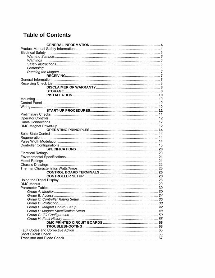
Table of Contents
GENERAL INFORMATION ........................................................................ 4 Product Manual Safety Information ........................................................................................ 4 Electrical Safety ..................................................................................................................... 5
Warning Symbols ............................................................................................................ 5 Warnings ......................................................................................................................... 5 Safety Instructions ........................................................................................................... 6 Grounding ........................................................................................................................ 6 Running the Magnet ........................................................................................................ 7
RECEIVING ................................................................................................. 7 General Information ............................................................................................................... 7 Receiving Check List .............................................................................................................. 8
DISCLAIMER OF WARRANTY .................................................................. 8 STORAGE ................................................................................................... 8 INSTALLATION ........................................................................................ 10
Mounting .............................................................................................................................. 10 Control Panel ....................................................................................................................... 10 Wiring ................................................................................................................................... 10
START-UP PROCEDURES ...................................................................... 11 Preliminary Checks .............................................................................................................. 11 Operator Controls ................................................................................................................. 12 Cable Connections ............................................................................................................... 12 DMC Magnet Power-up ........................................................................................................ 12
OPERATING PRINCIPLES ...................................................................... 14 Solid-State Control ............................................................................................................... 14 Regeneration ........................................................................................................................ 14 Pulse Width Modulation ....................................................................................................... 14 Controller Configurations ..................................................................................................... 15
SPECIFICATIONS .................................................................................... 20 Electrical Ratings ................................................................................................................. 20 Environmental Specifications ............................................................................................... 21 Model Ratings ...................................................................................................................... 21 Chassis Drawings ................................................................................................................ 22 Thermal Characteristics Watts/Amps ................................................................................... 25
CONTROL BOARD TERMINALS ............................................................ 26 CONTROLLER SETUP ............................................................................ 28
Using the Digital Display ...................................................................................................... 28 DMC Menus ......................................................................................................................... 29 Parameter Tables ................................................................................................................. 30
Group A: Monitor ........................................................................................................... 30 Group B: Access ........................................................................................................... 34 Group C: Controller Rating Setup ................................................................................. 35 Group D: Protection....................................................................................................... 38 Group E: Magnet Control Setup .................................................................................... 42 Group F: Magnet Specification Setup ........................................................................... 48 Group G: I/O Configuration ........................................................................................... 50 Group H: Fault History .................................................................................................. 55
DMC PRINTED CIRCUIT BOARDS ......................................................... 56 TROUBLESHOOTING .............................................................................. 63
Fault Codes and Corrective Action ...................................................................................... 63 Short Circuit Check .............................................................................................................. 66 Transistor and Diode Check ................................................................................................ 67

MagnePulse DMC Manual
Part Number 144-45300 R4
4
General Information
Product Manual Safety Information
Magnetek, Inc. (Magnetek) offers a broad range of radio remote control products, control products and adjustable frequency drives, and industrial braking systems for overhead material handling applications. This manual has been prepared by Magnetek to provide information and recommendations for the installation, use, operation and service of Magnetek’s material handling products and systems (Magnetek Products). Anyone who uses, operates, maintains, services, installs or owns Magnetek Products should know, understand and follow our instructions and safety recommendations in this manual for Magnetek Products.
The recommendations in this manual do not take precedence over any of the following requirements relating to cranes, hoists and lifting devices:
Instructions, manuals, and safety warnings of the manufacturers of the equipment where the radio system is used,
Plant safety rules and procedures of the employers and the owners of facilities where the Magnetek Products are being used,
Regulations issued by the Occupational Health and Safety Administration (OSHA),
Applicable local, state or federal codes, ordinances, standards and requirements, or
Safety standards and practices for the overhead material handling industry.
This manual does not include or address the specific instructions and safety warnings of these manufacturers or any of the other requirements listed above. It is the responsibility of the owners, users and operators of the Magnetek Products to know, understand and follow all of these requirements. It is the responsibility of the owner of the Magnetek Products to make its employees aware of all of the above listed requirements and to make certain that all operators are properly trained. No one should use Magnetek Products prior to becoming familiar with and being trained in these requirements.
WARRANTY INFORMATION
For information on Magnetek’s product warranties by product type, please visit the Magnetek Material homepage on www.magnetek.com.

MagnePulse DMC Manual
Part Number 144-45300 R4
5
Electrical Safety Warning Symbols
For your own safety, please pay special attention to the instructions marked with these warning symbols:
= Dangerous Voltage
= General Warnings
= General Caution
Warnings
1 ONLY A QUALIFIED ELECTRICIAN SHOULD PERFORM THE ELECTRICAL INSTALLATION.
2 Internal components and circuit boards (except the isolated I/O terminals) are at utility potential when the MagnePulse DMC is connected to the line. This voltage is extremely dangerous and may cause death or severe injury if you come in contact with it.
3 When the MagnePulse DMC is connected to the utility, the line connections L1, L2, L11+ and capacitor connections are live even if the magnet is not running.
4 The drive control I/O terminals are isolated from the line potential through the interface board. The interface board may have dangerous external voltages connected through the control disconnect even when main power is removed by the main disconnect.
5 An upstream disconnect/protection device is to be used as noted in the National Electric Code (NEC).
6 Only spare parts obtained from a Magnetek authorized dealer can be used.
MagnePulse DMC Manual
Part Number 144-45300 R4
6
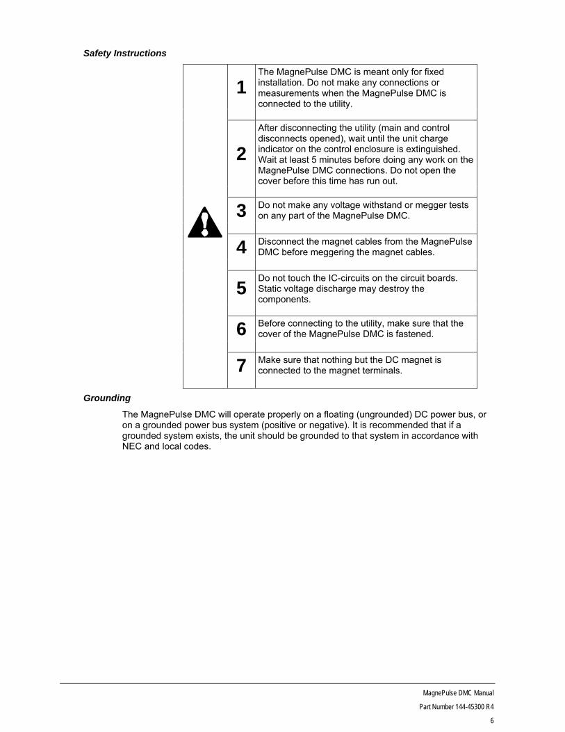
Safety Instructions
1The MagnePulse DMC is meant only for fixed installation. Do not make any connections or measurements when the MagnePulse DMC is connected to the utility.
2
After disconnecting the utility (main and control disconnects opened), wait until the unit charge indicator on the control enclosure is extinguished. Wait at least 5 minutes before doing any work on the MagnePulse DMC connections. Do not open the cover before this time has run out.
3 Do not make any voltage withstand or megger tests on any part of the MagnePulse DMC.
4 Disconnect the magnet cables from the MagnePulse DMC before meggering the magnet cables.
5Do not touch the IC-circuits on the circuit boards. Static voltage discharge may destroy the components.
6 Before connecting to the utility, make sure that the cover of the MagnePulse DMC is fastened.
7 Make sure that nothing but the DC magnet is connected to the magnet terminals.
Grounding
The MagnePulse DMC will operate properly on a floating (ungrounded) DC power bus, or on a grounded power bus system (positive or negative). It is recommended that if a grounded system exists, the unit should be grounded to that system in accordance with NEC and local codes.
MagnePulse DMC Manual
Part Number 144-45300 R4
7
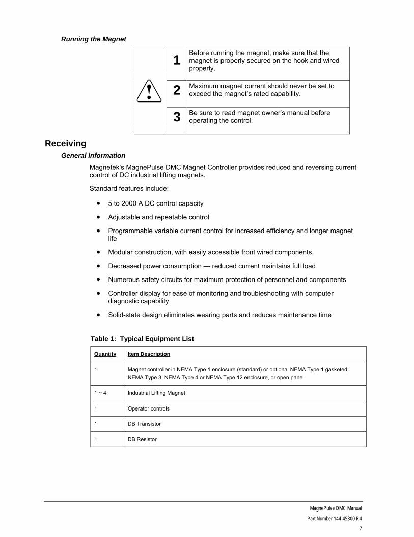
Running the Magnet
1Before running the magnet, make sure that the magnet is properly secured on the hook and wired properly.
2 Maximum magnet current should never be set to exceed the magnet’s rated capability.
3 Be sure to read magnet owner’s manual before operating the control.
Receiving General Information
Magnetek’s MagnePulse DMC Magnet Controller provides reduced and reversing current control of DC industrial lifting magnets.
Standard features include:
5 to 2000 A DC control capacity
Adjustable and repeatable control
Programmable variable current control for increased efficiency and longer magnet life
Modular construction, with easily accessible front wired components.
Decreased power consumption — reduced current maintains full load
Numerous safety circuits for maximum protection of personnel and components
Controller display for ease of monitoring and troubleshooting with computer diagnostic capability
Solid-state design eliminates wearing parts and reduces maintenance time
Table 1: Typical Equipment List
Quantity Item Description
1 Magnet controller in NEMA Type 1 enclosure (standard) or optional NEMA Type 1 gasketed,
NEMA Type 3, NEMA Type 4 or NEMA Type 12 enclosure, or open panel
1 ~ 4 Industrial Lifting Magnet
1 Operator controls
1 DB Transistor
1 DB Resistor
MagnePulse DMC Manual
Part Number 144-45300 R4
8
Receiving Check List
Upon receipt, check each item against the packing slip to ensure the item is the same as ordered.
If shipping damage is noted, contact and file a claim with the carrier immediately.
If there is a discrepancy between the packing slip and received items, contact Magnetek immediately to resolve.
If there is a discrepancy between your purchase order and the received items, contact Magnetek immediately to resolve.
Disclaimer of Warranty Magnetek, hereafter referred to as company, assumes no responsibility for improper programming of a control by untrained personnel. A control should only be programmed by a trained technician who has read and understands the contents of this manual. Improper programming of a control can lead to unexpected, undesirable, or unsafe operation or performance of the control. This may result in damage to equipment or personal injury. Company shall not be liable for economic loss, property damage, or other consequential damages or physical injury sustained by the purchaser or by any third party as a result of such programming. Company neither assumes nor authorizes any other person to assume for Company any other liability in connection with the sale or use of this product.
WARNING Improper programming of a control can lead to unexpected, undesirable, or unsafe operation or performance of the control.
Storage
Long Term Storage
Powering up the MagnePulse DMC every six months is quite beneficial. Over longer periods of time without power, the controls’ electrolytic DC bus capacitors require reformation, especially if stored in an area of high temperatures. Capacitor reforming is required if controllers are stored without power for more than 1 to 2 years. This process can be avoided by powering up the control bi-annually for 30 to 60 minutes.
NOTE Bus cap reforming alone may not restore full control functionality after 1 to 2 years of storage without power.
Controls contain large bus capacitors that have the potential to be reformed. However, printed circuit boards also contain electrolytic capacitors that may not function after several years without power. Magnetek recommends replacing the PCBs should the control’s functionality not be restored after bus cap reforming.
Capacitor Reforming
The electrical characteristics of aluminum electrolytic capacitors are dependent on temperature; the higher the ambient temperature, the faster the deterioration of the electrical characteristics (i.e., leakage current increase, capacitance drop, etc.). If an aluminum electrolytic capacitor is exposed to high temperatures such as direct sunlight, heating elements, etc., the life of the capacitor may be adversely affected. When capacitors are stored under humid conditions for long periods of time, the humidity will cause the lead wires and terminals to oxidize, which impairs their solderability. Therefore, aluminum electrolytic capacitors should be stored at room temperature, in a dry location and out of direct sunlight.
In the event that a capacitor has been stored in a high ambient environment for more than 1 or 2 years, a voltage treatment reformation process to electrolytic capacitors may have to
MagnePulse DMC Manual
Part Number 144-45300 R4
9
be performed. When stored above room temperatures for long periods of time, the anode foil may react with the electrolyte, increasing the leakage current. After storage, the application of even normal voltages to these capacitors may result in higher than normal leakage currents. In most cases the leakage current levels will decrease in a short period of time as the normal chemical reaction within the capacitor occurs. However, in extreme cases, the amount of gas generated may cause the safety vent to open.
Capacitors, when used in controls that are stored for long periods of time, should be subjected to a voltage treatment/reforming process as noted below, which will reform the dielectric and return the leakage current to the initial level.
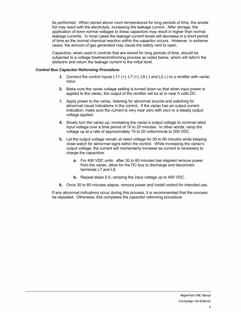
Control Bus Capacitor Reforming Procedure:
1. Connect the control inputs L11 (+), L7 (+), L8 (-) and L2 (-) to a rectifier with variac input.
2. Make sure the variac voltage setting is turned down so that when input power is applied to the variac, the output of the rectifier will be at or near 0 volts DC.
3. Apply power to the variac, listening for abnormal sounds and watching for abnormal visual indications in the control. If the variac has an output current indication, make sure the current is very near zero with zero or a steady output voltage applied.
4. Slowly turn the variac up, increasing the variac’s output voltage to nominal rated input voltage over a time period of 10 to 20 minutes. In other words, ramp the voltage up at a rate of approximately 10 to 20 volts/minute to 200 VDC.
5. Let the output voltage remain at rated voltage for 30 to 60 minutes while keeping close watch for abnormal signs within the control. While increasing the variac’s output voltage, the current will momentarily increase as current is necessary to charge the capacitors.
a. For 400 VDC units: after 30 to 60 minutes has elapsed remove power from the variac, allow for the DC bus to discharge and disconnect terminals L7 and L8.
b. Repeat steps 2-5, ramping the input voltage up to 400 VDC.
6. Once 30 to 60 minutes elapse, remove power and install control for intended use.
If any abnormal indications occur during this process, it is recommended that the process be repeated. Otherwise, this completes the capacitor reforming procedure.
MagnePulse DMC Manual
Part Number 144-45300 R4
10
Installation
DANGER Hazard of Electrical Shock or Burn
Up to 600 volts may exist in this controller. Use extreme care to avoid unpleasant or lethal shock. Disconnect input power before wiring and/or servicing motor or control.
Mounting
Mount and secure components as instructed below and in accordance with information on the dimension and control drawing included with the equipment.
Control Panel
Refer to the referenced dimension drawing for dimensions and mounting hole locations. Use all mounting holes. Install controller in a ventilated, clean, dry atmosphere. Maximum ambient temperature must not exceed 122°F (50°C) and must avoid contaminated atmospheres (metal chips, water spray, acids, etc.) unless the design is suitable for these environments.
Wiring
Wire all equipment according to the control panel drawing included with the equipment. Observe all notes on diagrams and follow all NEC and local codes.
Note: Do not connect the magnet to controller at this time.
CAUTION
Observe local codes for correct wire size, grounding, etc. Input must be between 200 – 320 volts DC for standard controls and 360 – 600V DC for high voltage controls.

MagnePulse DMC Manual
Part Number 144-45300 R4
11
Start-Up Procedures The control panels are factory tested before shipment. However, certain additional tests and adjustments must be made on site to ensure safe operation for the specific magnet and application.
Note: If the controller does not operate during start-up despite correct adjustments, check for: (1) wiring errors, (2) loose connections, (3) grounds in wiring between magnet, controller, pushbuttons, and master switch, (4) magnet overload or magnet malfunctions, (5) incorrect line voltage or polarity.
Preliminary Checks 1. Be sure dirt, wire fragments, shipping wedges, etc., are removed from the controller if
present.
2. Check that wiring is correct, screws are tight and vent holes are clear.
CAUTION Never use a megger to check wiring unless ALL electronic boards are removed, and IGBTs and diodes are jumpered from anode to cathode or disconnected.
3. If magnet megger check is required, ensure that all magnet leads are disconnected at the magnet conduit box.
4. Check to ensure that the magnet area is free of metal and electronic products.
.
1 This equipment is applicable to high voltage systems. Only qualified technicians should install the MagnePulse DMC Magnet control panels.
2 Safety glasses should be worn at all times. Proper clothing should also be worn.
3 Personnel should shield/remove any machinery that can be caused to move by the magnet being controlled to prevent damage.
4 The magnet should be resting on a solid surface.
5 Whenever voltage has been disconnected from the controller, the capacitor bank can take up to 5 minutes for the voltage to reduce to a safe level.
MagnePulse DMC Manual
Part Number 144-45300 R4
12
Operator Controls The operator controls must be wired as shown in the schematic diagram shipped with the control panel.
Cable Connections Power supply and magnet connections should be verified before being connected securely to the controller.
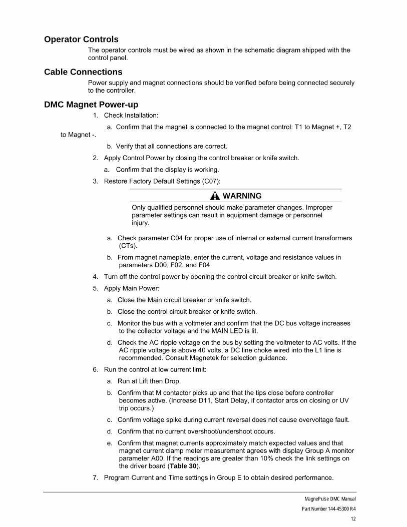
DMC Magnet Power-up 1. Check Installation:
a. Confirm that the magnet is connected to the magnet control: T1 to Magnet +, T2 to Magnet -.
b. Verify that all connections are correct.
2. Apply Control Power by closing the control breaker or knife switch.
a. Confirm that the display is working.
3. Restore Factory Default Settings (C07):
WARNING Only qualified personnel should make parameter changes. Improper parameter settings can result in equipment damage or personnel injury.
a. Check parameter C04 for proper use of internal or external current transformers (CTs).
b. From magnet nameplate, enter the current, voltage and resistance values in parameters D00, F02, and F04
4. Turn off the control power by opening the control circuit breaker or knife switch.
5. Apply Main Power:
a. Close the Main circuit breaker or knife switch.
b. Close the control circuit breaker or knife switch.
c. Monitor the bus with a voltmeter and confirm that the DC bus voltage increases to the collector voltage and the MAIN LED is lit.
d. Check the AC ripple voltage on the bus by setting the voltmeter to AC volts. If the AC ripple voltage is above 40 volts, a DC line choke wired into the L1 line is recommended. Consult Magnetek for selection guidance.
6. Run the control at low current limit:
a. Run at Lift then Drop.
b. Confirm that M contactor picks up and that the tips close before controller becomes active. (Increase D11, Start Delay, if contactor arcs on closing or UV trip occurs.)
c. Confirm voltage spike during current reversal does not cause overvoltage fault.
d. Confirm that no current overshoot/undershoot occurs.
e. Confirm that magnet currents approximately match expected values and that magnet current clamp meter measurement agrees with display Group A monitor parameter A00. If the readings are greater than 10% check the link settings on the driver board (Table 30).
7. Program Current and Time settings in Group E to obtain desired performance.

MagnePulse DMC Manual
Part Number 144-45300 R4
13
a. Confirm voltage spike during current reversal does not cause overvoltage fault.
CAUTION Using extreme caution, confirm that the CDBR and resistor can safely discharge the magnet energy. Measure resistor current and duty cycle to verify the CDBR and resistor is not being overworked.
WARNING Only qualified personnel should make parameter changes. Improper parameter settings can result in equipment damage or personnel injury.
MagnePulse DMC Manual
Part Number 144-45300 R4
14
Operating Principles
Solid-State Control
The MagnePulse DMC is a controller designed for industrial lifting magnets. Unlike typical systems that use contactors to reverse current, the MagnePulse DMC uses high-speed power semiconductor switches with controlled ON/OFF duty cycles in order to control magnet current. When the semiconductor switches are fully ON, their voltage drop is typically less than 2V, therefore the power they dissipate is a small fraction of the power that they control. Unlike resistive current control in switched stages, control by semiconductors can be made smooth and step-less. Furthermore, characteristics can easily be varied to suit a specific application or process.
Regeneration
MagnePulse DMC is a fully regenerative controller. This means that the energy stored in the magnet coils will regenerate back to the DC bus capacitors during periods of fast current transients. The efficiency of the controller is sufficiently high to allow it to recover some energy from the load and return it to the DC supply. If the DC supply cannot absorb the magnet’s energy a DB transistor and resistor is required.
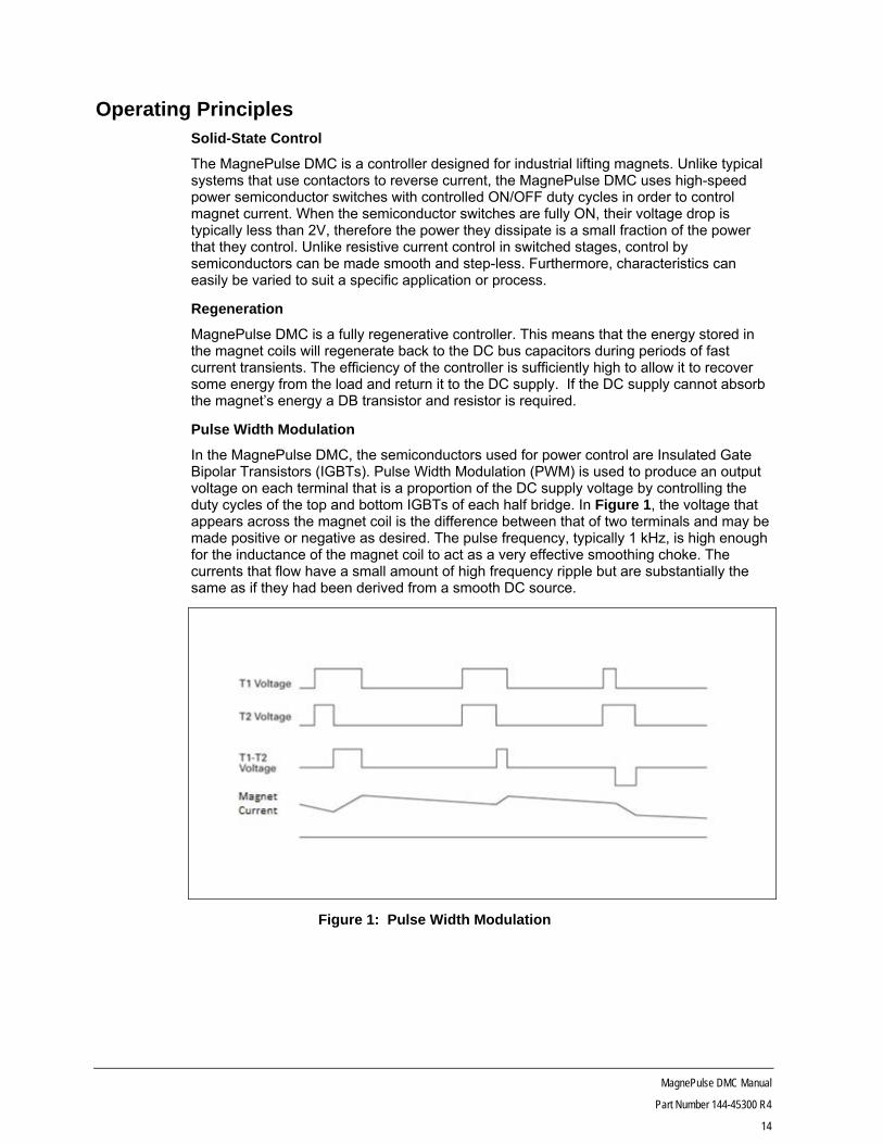
Pulse Width Modulation
In the MagnePulse DMC, the semiconductors used for power control are Insulated Gate Bipolar Transistors (IGBTs). Pulse Width Modulation (PWM) is used to produce an output voltage on each terminal that is a proportion of the DC supply voltage by controlling the duty cycles of the top and bottom IGBTs of each half bridge. In Figure 1, the voltage that appears across the magnet coil is the difference between that of two terminals and may be made positive or negative as desired. The pulse frequency, typically 1 kHz, is high enough for the inductance of the magnet coil to act as a very effective smoothing choke. The currents that flow have a small amount of high frequency ripple but are substantially the same as if they had been derived from a smooth DC source.
Figure 1: Pulse Width Modulation
MagnePulse DMC Manual
Part Number 144-45300 R4
15
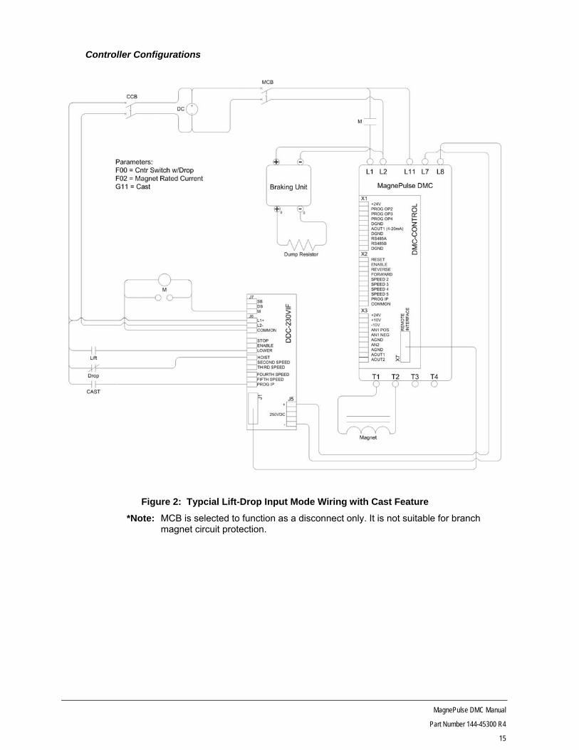
Controller Configurations
Figure 2: Typcial Lift-Drop Input Mode Wiring with Cast Feature
*Note: MCB is selected to function as a disconnect only. It is not suitable for branch magnet circuit protection.
MagnePulse DMC Manual
Part Number 144-45300 R4
16
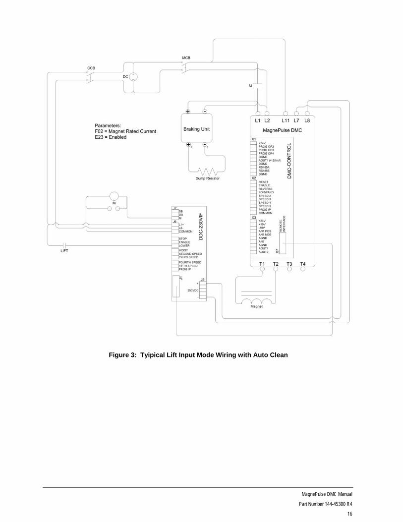
Figure 3: Tyipical Lift Input Mode Wiring with Auto Clean

MagnePulse DMC Manual
Part Number 144-45300 R4
17
Figure 4: Typical Analog Input Mode Wiring

MagnePulse DMC Manual
Part Number 144-45300 R4
18
Figure 5: Typical Stepped Current Input Mode Wiring

MagnePulse DMC Manual
Part Number 144-45300 R4
19
Figure 6: Typical Lift-Drop Input Mode Wiring with OmniBeam Feature

MagnePulse DMC Manual
Part Number 144-45300 R4
20
Specifications Electrical Ratings
Table 2: Electrical Ratings
Description Specification
Power
Current Range 5 amps to 2000 amps continuous
Supply Bus Voltage +10% to -20%
200 to 320V DC Standard 360 to 640V DC Optional
Grounding Configurations Full Floating, Grounded Positive, or Grounded Negative
DV/DT Rise 1500 volts per microsecond maximum
Switching Frequency 1 kHz
Control I/O
Digital Inputs DMC-CONTROL 8 inputs (24 VDC)
DDC-230VIF 8 inputs (200-300 VDC)
DMC-120A60IF 8 inputs (120 VAC, +10/-15%, 60±3 Hz)
Digital Outputs DMC-CONTROL 3 outputs (24 VDC, 40 mA)
DDC-230VIF 2 programmable, 1 main line (230 VDC, 1A)
DMC-120A60IF 2 programmable, 1 main line (120 VAC/30 VDC, 1A)
Analog Inputs DMC-CONTROL 2 inputs (0-10 VDC or 4-20 mA, 250Ω)
Analog Outputs DMC-CONTROL 2 outputs (0-10 VDC or 4-20 mA, 250Ω)
Communication
RS-232 Modbus RTU
RS-485 Modbus RTU
Protective Functions
Reverse Polarity Software and hardware detection
Power Loss One second control Ride-Through capability
Power circuit Ride-Through time is proportional to magnet current
Undervoltage Trip @ less than 50% Vin for greater than one second
Control Magnet Short Circuit Current Control Overload Trip IGBT Individual Overload Trip IGBT Overcurrent Safe Failure Mode
Control Thermal Heat Sink Overtemperature Alarm and Shutdown Enclosure Overtemperature Shutdown
Magnet Thermal Resistive Temperature Trip
Magnet Overload Electronic Time trip
Magnet Continuity Continuous
Fuse Protection DC BUS Power Fuse Interface Board Fused
Charge Indicator Visual indicator on control unit indicating charge state on the capacitor bank. Backlight display indicates control voltage presence.
Magnet Ground Detection Trip level is hardware set and is non-adjustable.
MagnePulse DMC Manual
Part Number 144-45300 R4
21
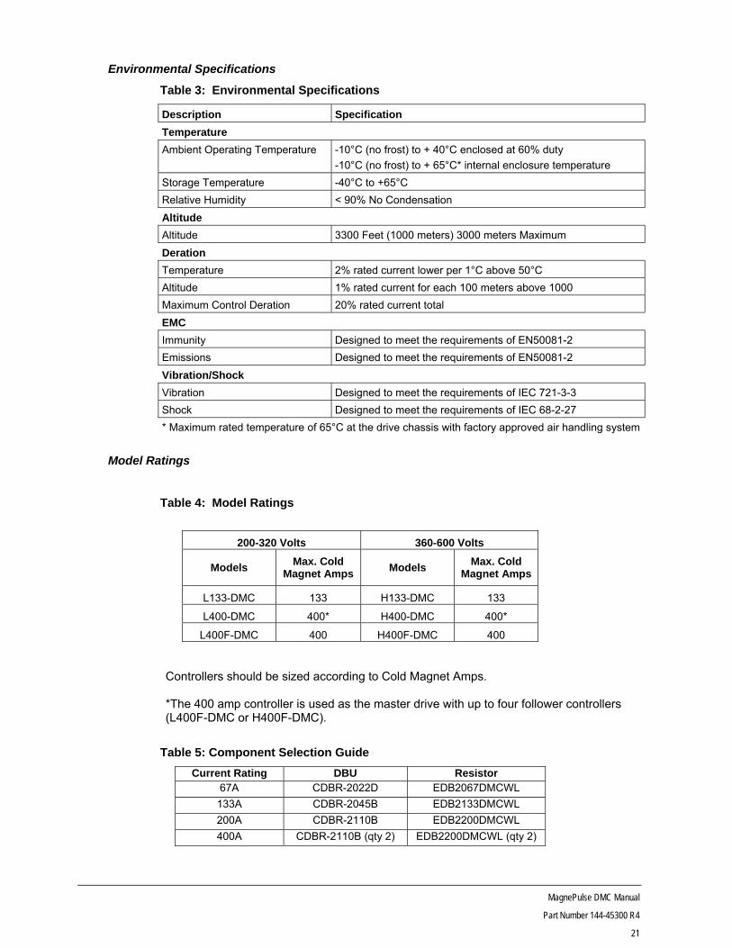
Environmental Specifications
Table 3: Environmental Specifications
Description Specification
Temperature
Ambient Operating Temperature -10°C (no frost) to + 40°C enclosed at 60% duty
-10°C (no frost) to + 65°C* internal enclosure temperature
Storage Temperature -40°C to +65°C
Relative Humidity < 90% No Condensation
Altitude
Altitude 3300 Feet (1000 meters) 3000 meters Maximum
Deration
Temperature 2% rated current lower per 1°C above 50°C
Altitude 1% rated current for each 100 meters above 1000
Maximum Control Deration 20% rated current total
EMC
Immunity Designed to meet the requirements of EN50081-2
Emissions Designed to meet the requirements of EN50081-2
Vibration/Shock
Vibration Designed to meet the requirements of IEC 721-3-3
Shock Designed to meet the requirements of IEC 68-2-27
* Maximum rated temperature of 65°C at the drive chassis with factory approved air handling system
Model Ratings
Table 4: Model Ratings
200-320 Volts 360-600 Volts
Models Max. Cold
Magnet Amps Models
Max. Cold Magnet Amps
L133-DMC 133 H133-DMC 133
L400-DMC 400* H400-DMC 400*
L400F-DMC 400 H400F-DMC 400 Controllers should be sized according to Cold Magnet Amps.
*The 400 amp controller is used as the master drive with up to four follower controllers (L400F-DMC or H400F-DMC).
Table 5: Component Selection Guide
Current Rating DBU Resistor67A CDBR-2022D EDB2067DMCWL
133A CDBR-2045B EDB2133DMCWL
200A CDBR-2110B EDB2200DMCWL
400A CDBR-2110B (qty 2) EDB2200DMCWL (qty 2)
MagnePulse DMC Manual
Part Number 144-45300 R4
22
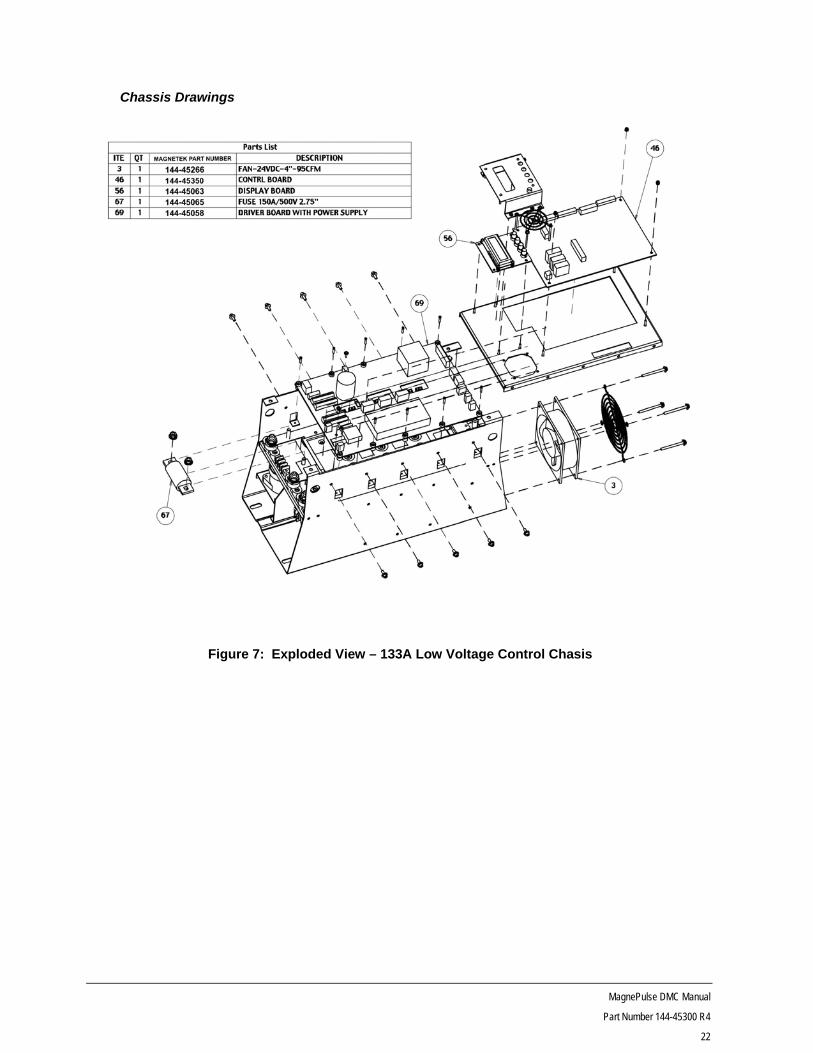
Chassis Drawings
Figure 7: Exploded View – 133A Low Voltage Control Chasis

MagnePulse DMC Manual
Part Number 144-45300 R4
23
Figure 8: Exploded View – 200/400 A and High Voltage Drive Chassis

MagnePulse DMC Manual
Part Number 144-45300 R4
24
Figure 9: 133A Low Voltage Control Chasis
Figure 10: 133A High Votlage and 400A Control Chasis
Table 6: Chassis Dimensions
Model Figure
Number Dimensions (in)
Weight W H D W1 W2 H1 t1 t2
L133-DMC 9 8.57 18.50 12.50 7.00 6.00 17.50 .35 .50 44 lbs. H133-DMC L400-DMC H400-DMC L400F-DMC H400F-DMC
10 13.17 30.00 14.17 -- 11.90 28.87 -- .50 119 lbs.
MagnePulse DMC Manual
Part Number 144-45300 R4
25
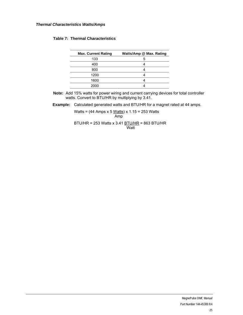
Thermal Characteristics Watts/Amps
Table 7: Thermal Characteristics
Max. Current Rating Watts/Amp @ Max. Rating
133 5
400 4
800 4
1200 4
1600 4
2000 4
Note: Add 15% watts for power wiring and current carrying devices for total controller watts. Convert to BTU/HR by multiplying by 3.41.
Example: Calculated generated watts and BTU/HR for a magnet rated at 44 amps.
Watts = (44 Amps x 5 Watts) x 1.15 = 253 Watts Amp
BTU/HR = 253 Watts x 3.41 BTU/HR = 863 BTU/HR Watt
MagnePulse DMC Manual
Part Number 144-45300 R4
26
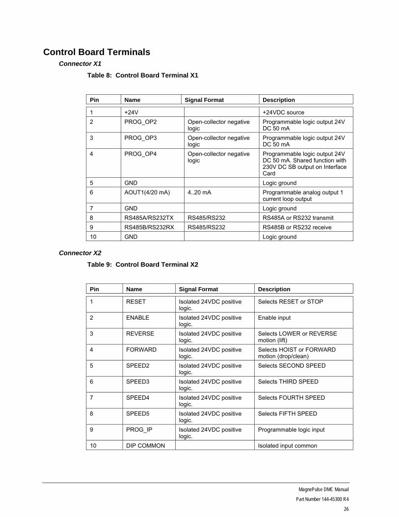
Control Board Terminals Connector X1
Table 8: Control Board Terminal X1
Pin Name Signal Format Description
1 +24V +24VDC source
2 PROG_OP2 Open-collector negative logic
Programmable logic output 24V DC 50 mA
3 PROG_OP3 Open-collector negative logic
Programmable logic output 24V DC 50 mA
4 PROG_OP4 Open-collector negative logic
Programmable logic output 24V DC 50 mA. Shared function with 230V DC SB output on Interface Card
5 GND Logic ground
6 AOUT1(4/20 mA) 4..20 mA Programmable analog output 1 current loop output
7 GND Logic ground
8 RS485A/RS232TX RS485/RS232 RS485A or RS232 transmit
9 RS485B/RS232RX RS485/RS232 RS485B or RS232 receive
10 GND Logic ground
Connector X2
Table 9: Control Board Terminal X2
Pin Name Signal Format Description
1 RESET Isolated 24VDC positive logic.
Selects RESET or STOP
2 ENABLE Isolated 24VDC positive logic.
Enable input
3 REVERSE Isolated 24VDC positive logic.
Selects LOWER or REVERSE motion (lift)
4 FORWARD Isolated 24VDC positive logic.
Selects HOIST or FORWARD motion (drop/clean)
5 SPEED2 Isolated 24VDC positive logic.
Selects SECOND SPEED
6 SPEED3 Isolated 24VDC positive logic.
Selects THIRD SPEED
7 SPEED4 Isolated 24VDC positive logic.
Selects FOURTH SPEED
8 SPEED5 Isolated 24VDC positive logic.
Selects FIFTH SPEED
9 PROG_IP Isolated 24VDC positive logic.
Programmable logic input
10 DIP COMMON Isolated input common

MagnePulse DMC Manual
Part Number 144-45300 R4
27
Connector X3
Table 10: Control Board Terminal X3
Pin Name Signal Format Description
1 +24V 24V source (0.2A max, not isolated from logic ground).
2 +10V +10V analog reference (10 mA max)
3 -10V -10V analog reference (10 mA max)
4 ANALOG IP 1(+) -10..+10V or 4.. 20 mA differential
Programmable analog input 1 – high
5 ANALOG IP 1(-) Programmable analog input 1 – low
6 ANALOG GND Analog ground
7 ANALOG IP 2 0..10V or 4..20 mA Programmable analog input 2
8 ANALOG GND Analog ground
9 AOUT1(0/10V) 0V..+10V Programmable analog output 1
10 CURRENT 0V..+10V Magnet current signal (absolute)
MagnePulse DMC Manual
Part Number 144-45300 R4
28
Controller Setup
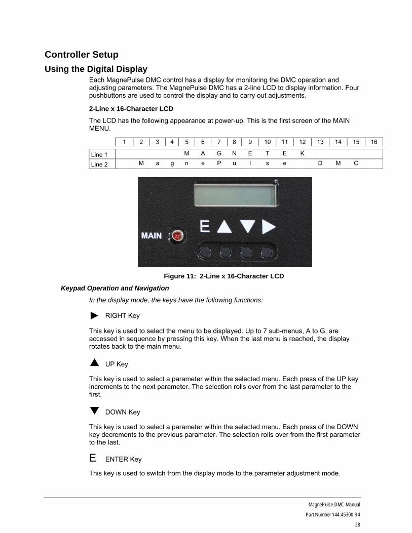
Using the Digital Display Each MagnePulse DMC control has a display for monitoring the DMC operation and adjusting parameters. The MagnePulse DMC has a 2-line LCD to display information. Four pushbuttons are used to control the display and to carry out adjustments.
2-Line x 16-Character LCD
The LCD has the following appearance at power-up. This is the first screen of the MAIN MENU.
1 2 3 4 5 6 7 8 9 10 11 12 13 14 15 16
Line 1 M A G N E T E K
Line 2 M a g n e P u l s e D M C
Figure 11: 2-Line x 16-Character LCD
Keypad Operation and Navigation
In the display mode, the keys have the following functions:
RIGHT Key
This key is used to select the menu to be displayed. Up to 7 sub-menus, A to G, are accessed in sequence by pressing this key. When the last menu is reached, the display rotates back to the main menu.
UP Key
This key is used to select a parameter within the selected menu. Each press of the UP key increments to the next parameter. The selection rolls over from the last parameter to the first.
DOWN Key
This key is used to select a parameter within the selected menu. Each press of the DOWN key decrements to the previous parameter. The selection rolls over from the first parameter to the last.
E ENTER Key
This key is used to switch from the display mode to the parameter adjustment mode.
MagnePulse DMC Manual
Part Number 144-45300 R4
29
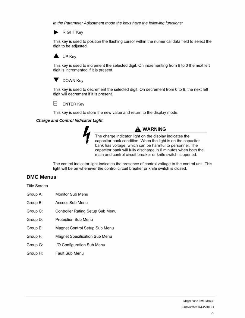
In the Parameter Adjustment mode the keys have the following functions:
RIGHT Key
This key is used to position the flashing cursor within the numerical data field to select the digit to be adjusted.
UP Key
This key is used to increment the selected digit. On incrementing from 9 to 0 the next left digit is incremented if it is present.
DOWN Key
This key is used to decrement the selected digit. On decrement from 0 to 9, the next left digit will decrement if it is present.
E ENTER Key
This key is used to store the new value and return to the display mode.
Charge and Control Indicator Light
WARNING
The charge indicator light on the display indicates the capacitor bank condition. When the light is on the capacitor bank has voltage, which can be harmful to personnel. The capacitor bank will fully discharge in 6 minutes when both the main and control circuit breaker or knife switch is opened.
The control indicator light indicates the presence of control voltage to the control unit. This light will be on whenever the control circuit breaker or knife switch is closed.
DMC Menus
Title Screen
Group A: Monitor Sub Menu
Group B: Access Sub Menu
Group C: Controller Rating Setup Sub Menu
Group D: Protection Sub Menu
Group E: Magnet Control Setup Sub Menu
Group F: Magnet Specification Sub Menu
Group G: I/O Configuration Sub Menu
Group H: Fault Sub Menu

MagnePulse DMC Manual
Part Number 144-45300 R4
30
Parameter Tables Group A: Monitor
Table 11: Magnet Current and Voltage
Variable Number Name Function Unit
A00 Magnet Current Displays the value of magnet current derived from controller terminal T1 current measurement.
0.1A
A02 Magnet Voltage Displays the value of the magnet voltage measurement derived from controller terminals T1 and T2.
0.1V
A03 DC Bus Voltage Displays the voltage on the controller DC bus capacitors.
0.1V
Table 12: Magnet Status
Variable Number Name Function Unit
A04 Magnet Res Magnet Calculated Resistance (Note: only calculated during steady state current by I Agree)
0.001 Ohm
A05 Magnet Temp Magnet Calculated Temperature (Note: calculated using cold magnet resistance parameters and steady state magnet resistance)
C
A08 Control Ref Input reference from master switch/analog reference 0.1%
Table 13: Control Power, Energy, and Operation Cycles
Variable Number Name Function Unit
A09 Input Power Displays instantaneous power input from the main DC supply.
kW
A10 Energy Used Displays the accumulated energy used by the controller.
0.1 kWh
A11 No of Operations Operation Counter (99 max. count after which counter resets to zero).
1
A12 No of Operations x 100
Operation Counter (increments 1 for every 100 operations up to 65,535 after which it resets to zero).
100
A13 Elapsed Hours Accumulated time controller is enabled. 1 hr
Table 14: Analog Input Status
Variable Number Name Function Unit
A14 Analog Input 1 Displays the % full scale of analog input 1. 0.1%
A15 Analog Input 2 Displays the % full scale of analog input 2. 0.1%
Table 15: Current Control
Variable Number Name Function Unit
A16 Magnet Current Ref
Displays the magnet calculated current reference as a percentage of the magnet(s) rated current.
0.1%
A17 Magnet FB Rel Displays the relative magnet current feedback as a percentage of the magnet(s) rated current.
0.1%

MagnePulse DMC Manual
Part Number 144-45300 R4
31
Table 16: I/O Status
Variable Number Name Function Unit
A21 Logic Inputs Bit 0 is the display’s right-most bit
Bit 0: Enable
Bit 1: Forward (Drop)
Bit 2: Reverse (Lift)
Bit 3: Speed 2
Bit 4: Speed 3
Bit 5: Speed 4
Bit 6: Speed 5
Bit 7: Not Used
Bit 8: Programmable Input
Bit 9: Module Fault
Bit 10: Module Out of Service
Bit 11: Power Supply Loss
Bit 12: Ground Fault
Bit
A22 Logic Outputs Bit 0 is the display’s right-most bit
Bit 0: M Contactor (Interface Board - M)
Bit 1: Prog OP 1 (Interface Board - DB)
Bit 2: Prog OP 2
Bit 3: Prog OP 3
Bit 4: Prog OP 4 (Interface Board – SB)
Bit
Table 17: Controller Status
Variable Number Name Function Unit
A23 Heatsink Temp Displays the temperature of the semiconductor heatsink reading. 0.1°C
A24 Ambient Temp Displays the ambient temperature at the electronic control card reading. Fault at 75 ˚C reset at 65 ˚C
0.1C
A25 Overload Level Displays the accumulated value of magnet current overload. This register increments above 110% current and decrements when current falls below 110%. Fault occurs when value reaches 18000.
1
A26 T1 Duty Cycle (Advanced Tool)
Displays the PWM duty cycle (% time ON) at terminal T1 (connected to armature terminal A1).
0.1%
A27 T2 Duty Cycle (Advanced Tool)
Displays the PWM duty cycle (% time ON) at terminal T2 (connected to armature terminal A2).
0.1%

MagnePulse DMC Manual
Part Number 144-45300 R4
32
Controller Status (Continued)
Variable Number Name Function Unit
A29 Control Status (Advanced Tool)
Bit 0 is the display’s right-most bit Bit Bit 0: Control Enabled Bit 1: Direction Input Bit 2: Not Used Bit 3: Not Used Bit 4: Not Used Bit 5: Not Used Bit 6: Fault Bit 7: Under Voltage Bit 8: Not Used Bit 9: Not Used Bit 10: Not Used Bit 11: External Fault Maj Bit 12: Not Used Bit 13: Not Used Bit 14: Battery Enabled Bit 15: Not Used
0 = Ready Mode 1 = Run Mode 0 = Lift 1 = Drop 1 = Control in FAULT status 1 = Control Fault is Under Voltage 1 = External Fault input activated
MagnePulse DMC Manual
Part Number 144-45300 R4
33
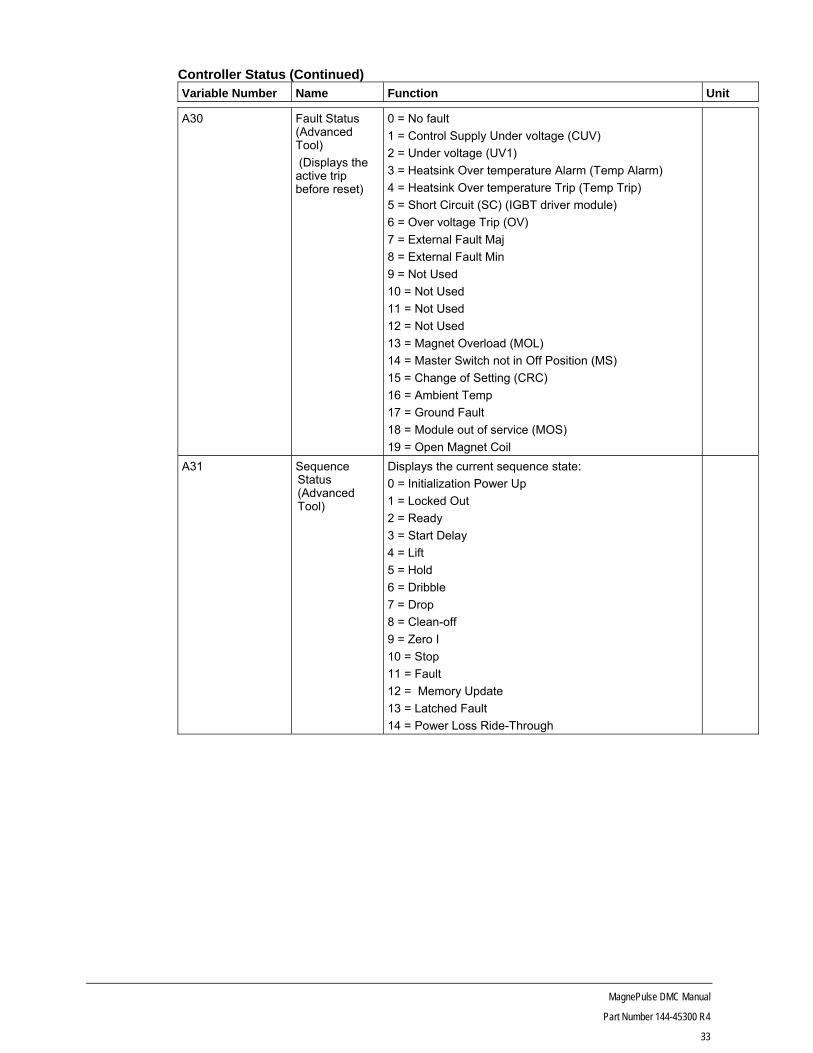
Controller Status (Continued) Variable Number Name Function Unit
A30 Fault Status (Advanced Tool)
(Displays the active trip before reset)
0 = No fault
1 = Control Supply Under voltage (CUV)
2 = Under voltage (UV1)
3 = Heatsink Over temperature Alarm (Temp Alarm)
4 = Heatsink Over temperature Trip (Temp Trip)
5 = Short Circuit (SC) (IGBT driver module)
6 = Over voltage Trip (OV)
7 = External Fault Maj
8 = External Fault Min
9 = Not Used
10 = Not Used
11 = Not Used
12 = Not Used
13 = Magnet Overload (MOL)
14 = Master Switch not in Off Position (MS)
15 = Change of Setting (CRC)
16 = Ambient Temp
17 = Ground Fault
18 = Module out of service (MOS)
19 = Open Magnet Coil
A31 Sequence Status (Advanced Tool)
Displays the current sequence state:
0 = Initialization Power Up
1 = Locked Out
2 = Ready
3 = Start Delay
4 = Lift
5 = Hold
6 = Dribble
7 = Drop
8 = Clean-off
9 = Zero I
10 = Stop
11 = Fault
12 = Memory Update
13 = Latched Fault
14 = Power Loss Ride-Through
MagnePulse DMC Manual
Part Number 144-45300 R4
34
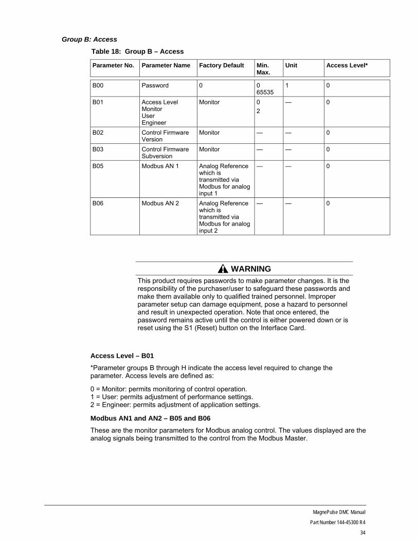
Group B: Access
Table 18: Group B – Access
Parameter No. Parameter Name Factory Default Min. Max.
Unit Access Level*
B00 Password 0 0 65535
1 0
B01 Access Level Monitor User Engineer
Monitor 0
2
— 0
B02 Control Firmware Version
Monitor — — 0
B03 Control Firmware Subversion
Monitor — — 0
B05 Modbus AN 1 Analog Reference which is transmitted via Modbus for analog input 1
— — 0
B06 Modbus AN 2 Analog Reference which is transmitted via Modbus for analog input 2
— — 0
WARNING This product requires passwords to make parameter changes. It is the responsibility of the purchaser/user to safeguard these passwords and make them available only to qualified trained personnel. Improper parameter setup can damage equipment, pose a hazard to personnel and result in unexpected operation. Note that once entered, the password remains active until the control is either powered down or is reset using the S1 (Reset) button on the Interface Card.
Access Level – B01
*Parameter groups B through H indicate the access level required to change the parameter. Access levels are defined as:
0 = Monitor: permits monitoring of control operation. 1 = User: permits adjustment of performance settings. 2 = Engineer: permits adjustment of application settings.
Modbus AN1 and AN2 – B05 and B06
These are the monitor parameters for Modbus analog control. The values displayed are the analog signals being transmitted to the control from the Modbus Master.

MagnePulse DMC Manual
Part Number 144-45300 R4
35
Group C: Controller Rating Setup
Table 19: Group C – Controller Rating Setup
Parameter No. Parameter Name Factory Default Min.
Max.
Unit Access Level
C01 Voltage Class Set by DIP SW Position 4
0 = 200/360V
1 = 400/720V
1 0
C02 Current Class Set by DIP SW Position 1 & 2
0 = 67A
1 = 133A
2 = 200A
3 = 400A
*Note 1
1 0
C03 Parallel Stacks 1 1 5
*Note 1
1 2
C04 Magnet Setup 0 0 = Internal CT
1 = Ext CT 20A
2 = Ext CT10A
3 = Ext CT 5 A
*Note 2
1 2
C05 Input Bus Voltage 250 200 – 360 200 – 720
*Note 3
1V 2
C07 Default Values No Action 0 = No Action 1 = Store User 2 = Restore User 3 = Restore Factory
1 1
Note 1: When current class C02 switches are set to 400 A and the C03 value is greater than 1 the current class display will change with the C03 setting. When the DIP switches are set for 67 Amp and C04 External CT is selected the C02 will display 33A after the control is reset. Note 2: Internal CT default setting can only be changed when Current Class C02 is set to 67A setting. Note 3: Input Bus voltage range is dependent upon Voltage Class setting displayed in parameter C01.

MagnePulse DMC Manual
Part Number 144-45300 R4
36
Voltage Class – C01 This parameter defines the measurement scaling for the DC bus voltage; it must match the nameplate rating of the controller. Incorrect setting of this parameter will result in incorrectly scaled values for magnet voltages. Failure to set this parameter correctly will cause incorrect voltages to be indicated on the display. Reference Figure 15 and Table 27 for proper setting of position 4 on SW1.
Current Class – C02
This parameter defines the measurement scaling for magnet current, it must match the nameplate rating of the controller. Failure to set this parameter correctly will result in the magnet being operated at the wrong current. This will cause incorrect currents to be indicated on the display and will also cause the current limits and magnet overload protection to operate incorrectly. Reference Figure 15 and Table 27 for proper settings of position 1 and 2 on SW1. When SW1-1 and SW2-2 are on (400A setting) the current class display changes when parameter CO3 is greater than 1. See Table 20 in the Parallel Stacks description. Parallel Stacks – C03 This parameter is used when parallel converter units are combined with a 400A unit to obtain current capacities above 400A. This parameter must be equal to the total number of converter units including the master. Failure to set this parameter correctly will result in the magnet being operated at the wrong current. This will cause incorrect currents to be indicated on the display and will also cause the current limits and magnet overload protection to operate incorrectly. Parameter can only be changed if 400A switch position is on.
Table 20: Parallel Stacks Configuration
Controller Amps
Parameter Value
C02 Value
400 1 400amps
800 2 800amps
1200 3 1200amps
1600 4 1600amps
2000 5 2000amps
Magnet Setup – C04
This parameter defines where the current signals are derived, either from internal CTs or external CTs. External CTs require the use of the External CT field board on the T1 and T2 terminals.
The external CTs are only used with the 33A controls that are connected to magnets below 20A. The external CT board is mounted externally to the controller on the control panel. Refer to Figure 16 and Table 28 for jumper setting information.
When using the external CTs it is necessary to make sure that the jumper settings and the parameter setting (C04) agree to avoid operational problems. Also make sure that the jumper connections on driver board are according to Table 29. Whenever the external CT is selected the C02 parameter will display 33A. This is another quick check for the proper link settings on driver board. 133 AMP to 400 AMP switch positions will not allow the parameter to change from Internal CT.

MagnePulse DMC Manual
Part Number 144-45300 R4
37
Input Voltage – C05
Parameter specifies the nominal bus voltage of the DC supply system. It also sets the undervoltage trip point (50%) and the overvoltage trip point (140%). The maximum overvoltage trip point is limited to 420V in the low voltage control and 840V in the high voltage control. Default setting is determined by SW1 DIP Switch position 4 setting.
Default Values – C07
Provides the ability to store and restore the user parameter setup into the flash memory of the control. Also provides the ability to load factory default settings. Access to store and restore is provided by the engineering password level.
To store the user settings, select Store User Setting after all of the parameters are set and checked for accuracy.
To restore the user settings, select Restore User Setting.
To restore the factory settings, select the Restore Factory Setting. It will be necessary to reset the parameters for proper operation for the specific control and magnet used since the default settings are not control specific as the user settings are. This parameter is useful when first setting up the control or changing the control card.
The default settings will not become effective until the controller is powered down or reset through the S1 switch on the interface card.
WARNING Before installing a control board, whether from another control or from inventory, control board DIP switches and parameters must be properly programmed. Incorrect control setup can cause equipment damage or personnel injury.

MagnePulse DMC Manual
Part Number 144-45300 R4
38
Group D: Protection
Table 21: Group D - Protection
Parameter No.
Parameter Name Factory Default Min.
Max.
Unit Access Level
D00 Magnet Rated Volts 230 200 – 360 200 – 720 *Note 1
1V 2
D01 Magnet Volt Limit 0 0 – 360 0 – 720
1V 2
D03 Power Loss Level 200 0 – 360 0 – 720
1 V 2
D07 Ground Fault Disabled 0 = Enabled 1 = Disabled
1 2
D08 OH Alarm Level 85°C 70 85
1°C 2
D09 OH Trip Level 90°C 70 115
1 °C 2
D11 Start Delay 300 0 2500
1 ms 2
D12 Stop Delay 0 0 2500
1 ms 2
D14 Magnet Temp Alarm 0°C 0 700
1 °C 2
D15 Magnet OT Enable 0°C 0 800
1 °C 2
D16 OH Fan Enable 60.0°C 0 70.0
0.1 °C 2
D17 OA Temp Enable 75.0°C 0 95.0
0.1 °C 2
D18 MOC Detect Level 0.0 0.0 50.0
0.1% 2
D19 MOC Detect Time 0 0 2500
1 ms 2
D30 Reset Attempts 3 0 10
— 2
D31 Reset Flt Sel 0084 0000 03FF
— 2
Note 1: Input Bus voltage range is dependent upon Voltage Class setting displayed in parameter C01.
MagnePulse DMC Manual
Part Number 144-45300 R4
39
Magnet Rated Voltage – D00
This parameter is normally set to the magnet nameplate voltage rating. This parameter value is used to scale the magnet voltage feedback.
Rectified Systems When applying a standard 230V DC magnet to a 300 or 360V DC rectified system it will be necessary to adjust this parameter to obtain the correct display reading. For the 300V system, the values should be 1.3 times the nominal magnet ratings. For the 360V system, the values should be 1.57 times the nominal ratings. The multiplication factor is the ratio of the rectified volts over the nominal magnet volts. The magnet current does not change much, so it can remain at the magnet rated value.
CAUTION When applying this control to rectified systems make sure that the rectifier has the ability to handle the regenerative energy produced by the magnet. If it does not, additional equipment will be necessary to prevent controller faults from overvoltage.
Magnet Volt Limit – D01
This parameter will limit the output voltage to the magnet. Setting D01 to 0 will disable this feature.
Undervoltage Level – D03
This parameter defines the DC bus voltage level the control will enter the power loss ride-through state. Once in the power loss ride through state the control will base block, allowing the magnet current to charge the DC bus capacitors until the DC bus rises to C05. At which point the control will recharge the magnet until the magnet and DC bus are dissipated of their stored energy. Setting D03 to 0 disables the power loss ride-through feature.
Ground Fault – D07
This parameter enables the ground fault protection. LK10 on the driver board needs to be set open and the D07 must be changed to Enabled. The trip setting default is 50% of the controller continuous current rating displayed in parameter C02. LK12, found on the driver board, can adjust the trip level at 50%, 20%, 10%, or 5%.
OH Alarm Level – D08
This parameter sets the temperature level at which the semiconductor heatsink provides a warning of possible shutdown. When this temperature level is reached, the control will cut back the current and allow only 150% maximum current for the one minute cycle and not the 200% for three seconds. The level is adjustable from 70 to 85ºC.
OH Trip Level – D09
This parameter sets the heatsink temperature where the control will fault and shut down until the heatsink cools below the reset level of 90°C. The trip level is adjustable from 70 to 115ºC.
WARNING
A faulted control will disable magnet current and drop the load.

MagnePulse DMC Manual
Part Number 144-45300 R4
40
Start Delay – D11
This parameter allows time for the main contactor to close before the control loops activate the magnet. This delay will be present at the start of every requested cycle. If arcing occurs on the contact tips or UV trip occurs, extend the time to eliminate.
Stop Delay – D12
This parameter sets the time before the next lift cycle can be activated. To obtain the quickest ready state, set this parameter to 0.
Magnet Temperature Alarm – D14
This parameter sets magnet temperature that will set the magnet temperature alarm (MTA) and enable Alarm programmable output. This feature is used to notify the operator that an over temperature condition may occur during the current lift and should find a safe place to lower the load. Setting the parameter to 0 will disable the alarm feature.
Magnet OT Enable – D15
This parameter sets the magnet temperature that will set the magnet over temperature fault. The fault will consequently disable magnet current. Setting the parameter to 0 will disable the fault feature.
OH Fan Enable – D16
This parameter specifies heatsink temperature that the fan will turn on at. Lowering this parameter increases the semiconductor life expectancy, but decreases the fan’s life expectancy.
OA Temp Enable – D17
This parameter specifies the ambient temperature at the control board that the control will fault and shut down on an ambient over temperature (AOT) fault. Setting this parameter to 0 will disable the fault.
WARNING A faulted control will disable magnet current and drop the load.
MOC Detect Level – D18
This parameter specifies magnet current level that will enable a magnet open circuit (MOC) fault. Setting this parameter to zero disables the MOC fault.
WARNING
A faulted control will disable magnet current and drop the load.
MOC Detect Time – D19
This parameter specifies the duration the magnet current must be below the MOC Detect Level before a fault is logged.
Reset Attempts – D30
This parameter sets how many automatic reset attempts are allowed for the faults selected in D31. If the reset attempts max out, G11 or G22 could be used to reset a fault.

MagnePulse DMC Manual
Part Number 144-45300 R4
41
Reset Flt Sel – D31
This parameter selects what faults can be automatically reset when the fault condition is gone.
Digit 4 Digit 3 Digit 2 Digit 1
HEX 0 0 8 4
Binary 0 0 0 0 0 0 0 0 1 0 0 0 0 1 0 0
Bit 15 14 13 12 11 10 9 8 7 6 5 4 3 2 1 0
Bit Fault
Binary Number
Hexadecimal Conversion
0 CUV 0000 0
1 UV1 0001 1
2 OT1 0010 2
3 OV 0011 3
4 EXF 0100 4
5 EXFMN 0101 5
6 MOT 0110 6
7 AOT 0111 7
8 GF 1000 8
9 MOC 1001 9
10 Not used 1010 A
11 Not used 1011 B
12 Not used 1100 C
13 Not used 1101 D
14 Not used 1110 E
15 Not used 1111 F
Example: In this example, AOT, MOT, OV, and UV1 need to be resettable. UV1 corresponds to Bit 1, and should be set to a value of 1. OV corresponds to Bit 3, and should also be set to 1. Bits 1 and 3 contribute to the final value of Digit 1, resulting in a binary value of 1010. Per the binary to hexadecimal conversion chart, the binary value 1010 will convert to A. MOT and AOT correspond to Bits 6 and 7, so both should be set to 1. They contribute to the final value of Digit 2, resulting in a binary value of 1100, which converts into the hex value of C. Since the other bits are set to 0 for the other Digits (resulting in a binary and hex value of 0), the final value to be entered into Parameter D31 is 00CA.
Digit 4 Digit 3 Digit 2 Digit 1 HEX 0 0 C A Binary 0 0 0 0 0 0 0 0 1 1 0 0 1 0 1 0 Fault A G A A M F E O O U C O F O O O D X V T V U C T T T B F 1 1 V K
MagnePulse DMC Manual
Part Number 144-45300 R4
42
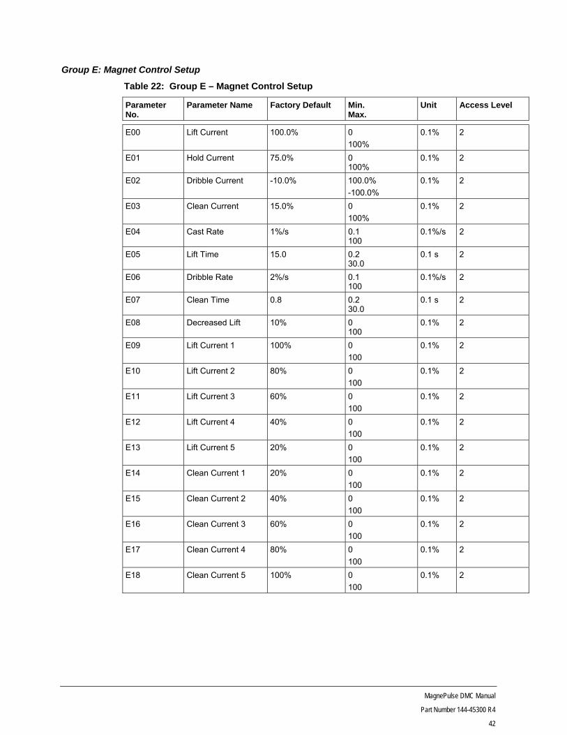
Group E: Magnet Control Setup
Table 22: Group E – Magnet Control Setup
Parameter No.
Parameter Name Factory Default Min. Max.
Unit Access Level
E00 Lift Current 100.0% 0
100%
0.1% 2
E01 Hold Current 75.0% 0 100%
0.1% 2
E02 Dribble Current -10.0% 100.0%
-100.0%
0.1% 2
E03 Clean Current 15.0% 0
100%
0.1% 2
E04 Cast Rate 1%/s 0.1 100
0.1%/s 2
E05 Lift Time 15.0 0.2 30.0
0.1 s 2
E06 Dribble Rate 2%/s 0.1 100
0.1%/s 2
E07 Clean Time 0.8 0.2 30.0
0.1 s 2
E08 Decreased Lift 10% 0 100
0.1% 2
E09 Lift Current 1 100% 0
100
0.1% 2
E10 Lift Current 2 80% 0
100
0.1% 2
E11 Lift Current 3 60% 0
100
0.1% 2
E12 Lift Current 4 40% 0
100
0.1% 2
E13 Lift Current 5 20% 0
100
0.1% 2
E14 Clean Current 1 20% 0
100
0.1% 2
E15 Clean Current 2 40% 0
100
0.1% 2
E16 Clean Current 3 60% 0
100
0.1% 2
E17 Clean Current 4 80% 0
100
0.1% 2
E18 Clean Current 5 100% 0
100
0.1% 2

MagnePulse DMC Manual
Part Number 144-45300 R4
43
Parameter No.
Parameter Name Factory Default Min. Max.
Unit Access Level
E20 I Agree 1.0 0
10.0
0.1% 2
E21 P Gain 1.0 0.1
50.0
0.1 2
E22 I Gain 0.2 0.1
50.0
0.1 2
E23 Auto Clean Disabled 0 = Enabled 1 = Disabled
1 2
Lift Current and Lift Time – E00 and E05
When using Lift or Lift-Drop input modes the Lift Current parameter sets the desired current level, as a percentage of magnet rated current, to pick and magnetize the load. Once both the Lift Current has been achieved and the Lift Time has expired the control will enter the Hold sequence.
Hold Current – E01
When using Lift or Lift-Drop input modes this parameter sets the desired current level, as a percentage of magnet rated current, to hold the magnetized load.
Dribble Current and Dribble Rate – E02 and E06
In Lift-Drop input mode the Dribble parameter sets the rate of reduction of magnet current when the Lift command is removed. Once the Dribble Current level has been achieved the magnet current is no longer reduced.

MagnePulse DMC Manual
Part Number 144-45300 R4
44
Clean Current and Clean Time – E03 and E07
When using Lift or Lift-Drop input modes the Clean Current parameter sets the desired current level, as a percentage of magnet rated current, to rapidly drop the load. In Lift input mode, once the Lift Time has expired the control will enter the Zero I sequence. In Lift-Drop input mode once the Clean Time has expired or the Drop command is removed the control will enter the Zero I sequence.
In Lift input mode the control enters the Drop sequence when the Lift command is removed.
In Lift-Drop input mode the control enters the Drop sequence when the Drop command is applied.
Figure 9: Example Lift-Drop Input Mode Current Profile

MagnePulse DMC Manual
Part Number 144-45300 R4
45
Cast Rate – E04
Cast Rate is enabled by PROG IP and parameter G11 and can be applied in Lift and Lift-Drop input modes. When the Cast feature is enabled the Hold current is reduced by the rate specified by this parameter. The Cast input is only active during the Hold state
Figure 10: Example Cast Feature Current Profile

MagnePulse DMC Manual
Part Number 144-45300 R4
46
Decreased Lift – E08
Decreased Lift is enabled by PROG IP and parameter G11 and is useful in Lift and Lift-Drop input modes. When the Decreased Lift feature is enabled it reduces the typical Lift and Hold currents by multiplying the Decreased Lift parameter by those Lift and Hold Current parameters.
Figure 11: Example Decreased Lift Feature Current Profile
Lift and Clean Current 1 ~ 5 – E09 ~ E18
Lift and Clean Current 1 ~ 5 parameters are used in Stepped I input mode. These parameters are used to set discrete current levels using the SPEED and direction inputs. The HOIST input enables Lift Current 1 and the DROP input enables Clean Current 1. For safety reasons if SPEED 4 input was lost and SPEED 3 and SPEED 5 inputs are enabled, the SPEED 3 setting will be used to maintain the load.
I Agree – E20
This parameter defines current window that the Magnet Current Reference (A16) parameter must be within the Magnet Current Feedback (A17) parameter to leave the lift sequence, enter the Clean sequence, and enable the temperature and resistance monitoring functions.
P Gain – E21
This parameter sets the current proportional gain and acts as the damper to the current loop. If this value is set too high the magnet current will vary erratically. If this value is set too low the current response will be sluggish and pick times will be increased.

MagnePulse DMC Manual
Part Number 144-45300 R4
47
I Gain – E22
This parameter sets the current integral gain and acts as the spring to the current loop and helps the current regulator respond quickly to changes in current demand.
Auto Clean – E23
When enabled this parameter automatically enters the Drop sequence when the Lift command is removed.
Enabled = Lift input mode
Disabled = Lift-Drop input

MagnePulse DMC Manual
Part Number 144-45300 R4
48
Group F: Magnet Specification Setup
Table 23: Group F – Magnet Specification Setup
Parameter No. Parameter Name Factory Default Min./Max. Unit Access Level
F00 Current Reference Source
Cntr Switch Cntr Switch Analog Ref 1 Analog Ref 2 Ser An Ref 1 Ser An Ref 2
— 2
F02 Magnet 1 Current C02/2 0 C02
0.1A 2
F03 Magnet 1 Inductance Gain
2.0 0.1 50.0
0.1%/s 2
F04 Magnet 1 Resistance
4.00 0.01 60.00
0.01 Ohm
2
F05 Magnet 2 Current 0 0 C02
0.1A 2
F06 Magnet 2 Inductance Gain
2.0 0.1 50.0
0.1%/s 2
F07 Magnet 2 Resistance
4.00 0.01 60.00
0.01 Ohm
2
F08 Magnet 3 Current 0 0 C02
0.1A 2
F09 Magnet 3 Inductance Gain
2.0 0.1 50.0
0.1%/s 2
F10 Magnet 3 Resistance
4.00 0.01 60.00
0.01 Ohm
2
F11 Magnet 4 Current 0 0 C02
0.1A 2
F12 Magnet 4 Inductance Gain
2.0 0.1 50.0
0.1%/s 2
F13 Magnet 4 Resistance
4.00 0.01 60.00
0.01 Ohm
2
Current Reference Source – F00
This parameter selects the source of the current reference. Cntr Switch setting allows inputs through the 230V DC interface card or 24V DC control card. The Cntr Switch setting is required for the following input modes: Lift, Lift-Drop, Stepped I.
The Analog Reference 1 setting directs the software to look at terminals X3-4, X3-5 and X3-6 on the control board for its voltage input. Analog Reference 2 directs the software to terminals X3-6 and X3-7 on the control card for the voltage input. Parameters G00 through G06 must also be set to operate properly.
Ser An 1 and Ser An 2 references are commanded using the Modbus RTU1 function codes 6 and 3 through the communication port (reference section 3.15 in Appendix A). The values received by the microprocessor can be monitored in parameters B05 and B06. Parameters G16 through G20 must also be set up properly to enable MODBUS communication and control.
Magnet 1 Current – F02
This parameter is the magnet current setting and should be set to the magnet’s full load nameplate rating. The default setting is 50% of the control Current Class rating parameter C02.
MagnePulse DMC Manual
Part Number 144-45300 R4
49
Magnet 1 Inductance Gain – F03
This parameter sets the rate of current reference change when decreasing the current in the magnet. Lower values will allow for smaller, slower voltage spikes on the DC bus. Higher values will allow for faster current response.
Magnet 1 Resistance – F04
This parameter must be set to the magnet’s cold resistance value (~25°C). The cold resistance is used to calculate current magnet temperature.
Magnet 2 ~ 4 Current – F05, F08, and F11
The Magnet 2 ~ 4 Current parameters are used when the SPEED IP function is set to OmniBeam. These parameters are used to scale the current delivered to magnets 2 ~ 4 when they are enabled. When various magnets are enabled the respective Magnet 1 ~ 4 Current parameters are summed to obtain the maximum current reference.
Magnet 2 ~ 4 Inductance Gain – F06, F09, and F12
These parameters function identically to F03 when the OmniBeam function is enabled. When various magnets are enabled the respective Inductance Gains are averaged.
Magnet 2 ~ 4 Resistance – F07, F10, and F13
These parameters function identically to F04 when the OmniBeam function is enabled. When various magnets are enabled the total resistance is calculated using the parallel resistance formula.
MagnePulse DMC Manual
Part Number 144-45300 R4
50
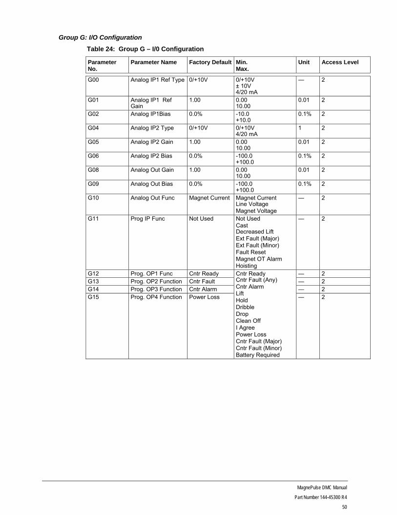
Group G: I/O Configuration
Table 24: Group G – I/0 Configuration
Parameter No.
Parameter Name Factory Default Min. Max.
Unit Access Level
G00 Analog IP1 Ref Type 0/+10V 0/+10V ± 10V 4/20 mA
— 2
G01 Analog IP1 Ref Gain
1.00 0.00 10.00
0.01 2
G02 Analog IP1Bias 0.0% -10.0 +10.0
0.1% 2
G04 Analog IP2 Type 0/+10V 0/+10V 4/20 mA
1 2
G05 Analog IP2 Gain 1.00 0.00 10.00
0.01 2
G06 Analog IP2 Bias 0.0% -100.0 +100.0
0.1% 2
G08 Analog Out Gain 1.00 0.00 10.00
0.01 2
G09 Analog Out Bias 0.0% -100.0 +100.0
0.1% 2
G10 Analog Out Func Magnet Current Magnet Current Line Voltage Magnet Voltage
— 2
G11 Prog IP Func Not Used Not Used Cast Decreased Lift Ext Fault (Major) Ext Fault (Minor) Fault Reset Magnet OT Alarm Hoisting
— 2
G12 Prog. OP1 Func Cntr Ready Cntr Ready Cntr Fault (Any) Cntr Alarm Lift Hold Dribble Drop Clean Off I Agree Power Loss Cntr Fault (Major) Cntr Fault (Minor) Battery Required
— 2 G13 Prog. OP2 Function Cntr Fault — 2 G14 Prog. OP3 Function Cntr Alarm — 2 G15 Prog. OP4 Function Power Loss — 2
MagnePulse DMC Manual
Part Number 144-45300 R4
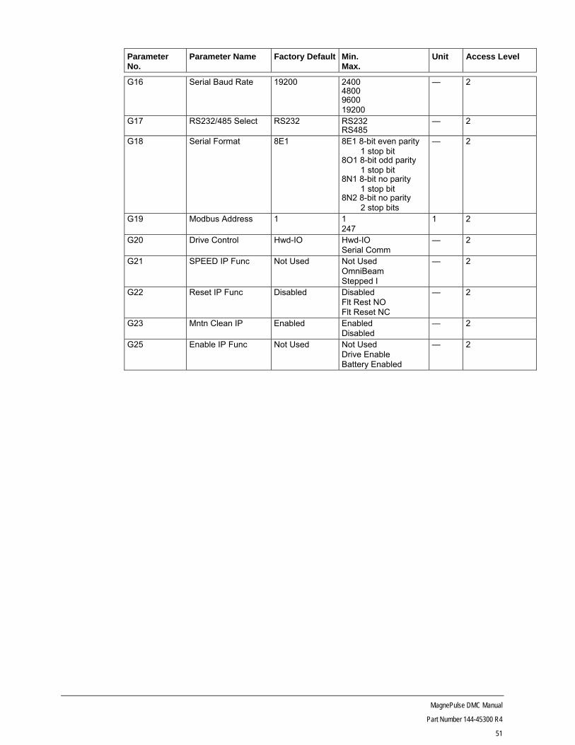
51
Parameter No.
Parameter Name Factory Default Min. Max.
Unit Access Level
G16 Serial Baud Rate 19200 2400 4800 9600 19200
— 2
G17 RS232/485 Select RS232 RS232 RS485
— 2
G18 Serial Format 8E1 8E1 8-bit even parity 1 stop bit 8O1 8-bit odd parity 1 stop bit 8N1 8-bit no parity 1 stop bit 8N2 8-bit no parity 2 stop bits
— 2
G19 Modbus Address 1 1 247
1 2
G20 Drive Control Hwd-IO Hwd-IO Serial Comm
— 2
G21 SPEED IP Func Not Used Not Used OmniBeam Stepped I
— 2
G22 Reset IP Func Disabled Disabled Flt Rest NO Flt Reset NC
— 2
G23 Mntn Clean IP Enabled Enabled Disabled
— 2
G25 Enable IP Func Not Used Not Used Drive Enable Battery Enabled
— 2
MagnePulse DMC Manual
Part Number 144-45300 R4
52
Analog IP1 and IP2 Type – G00 and G04
These parameters define the signal format for the analog inputs.
If the 4 to 20 mA signal is chosen for analog input 2, SW2-D on the control board must be moved to the ON position to connect the 250 ohm resistor to ground.
The SW2 switch on control board must be set up properly for analog input 1 usage. Refer to Table 26 for setting information of SW2 switch.
Analog IP1 and IP2 Gain – G01 and G05
Sets the input 1 scaling gain factor. A value of one means that 100% of the voltage or current signal equals 100% current command. A value of 3 means that 100% of the voltage or current signal equals 300% current command.
Analog IP1 and IP2 Bias – G02 and G06
This parameter allows the input signal to be offset by plus or minus 100%. The bias compensates for signal variances. It also can be used to limit the commanded speed range below 100%.
Analog Output Gain – G08
Determines the analog output scaling factor. A value of “1” means that 100% of the output variable produces a 10V signal at terminal X3-9 or a 20 mA signal at terminal X1-6. A value of “3” means that 33.3% of the output variable produces a 10V signal at terminal X3-9 or a 20 mA signal at terminal X1-6 and analog ground terminal X3-6.
Analog Out Bias – G09
This parameter allows the input signal to be offset by plus or minus 10%. The bias compensates for signal variances.
Analog Out Func – G10
This parameter selects the output function to be monitored via 0 to 10V signal at terminal X3-9 or the 4 to 20 mA signal available at terminal X1-6. Output functions available to monitor include: Magnet Current, Line Voltage, or Magnet Voltage.
Programmable IP – G11
Parameters G11 set up the function of the programmable logic and speed 5 inputs. This input can be 230V DC through the interface card slowdown terminal. It can also be a 24V DC input signal connected to the X2-9 terminal on the control card. Note that setting this parameter configures the same function for the 230V or 24V DC input.
Cast function when activated will reduce the magnet current in the Hold state at a preprogrammed rate. This function can only be used in the Lift or Lift-Drop input modes.
Decreased Lift function when activated will lessen the magnet current in the Lift and Hold states by a preprogrammed gain. This function can only be used in the Lift or Lift-Drop input modes.
External major fault when activated will shut the controller down and register the occurrence in the fault log. Input contact is NC.
External fault minor when activated will log the occurrence in the fault log and prevent initiation of the next lift sequence.
Fault Reset will clear a latched fault if the fault is no longer present and return the controller to the Ready state.
Magnet OT Alarm is intended to be used with a Klixon to notify the controller and operator an overtemperature condition has occurred in the magnet.
Hoisting when activated will bypass the lift time, E05, and enter the hold state.
MagnePulse DMC Manual
Part Number 144-45300 R4
53
Programmable OP1, OP2, OP3, and OP4 – G12 ~ G15
These parameters set the function for the programmable outputs. Programmable function selections are: Controller Ready, Controller Fault (any), Controller Alarm, Lift, Hold, Dribble, Drop, Clean Off, I Agree, Power Loss, Controller Fault (major), Controller Fault (minor), and Battery Required.
Prog OP1 is a 230V DC output and is located only on the Interface Card terminal DB.
Prog OP2 is a 24V 40 mA open-collector output on terminal X1-2 of the control card.
Prog OP3 is a 24V 40 mA open-collector output on terminal X1-3 of the control card.
Prog OP4 is a shared function. This is a 24V 40 mA open-collector output on terminal X1-4 of the control card and also a 230V DC output on the interface card terminal SB.
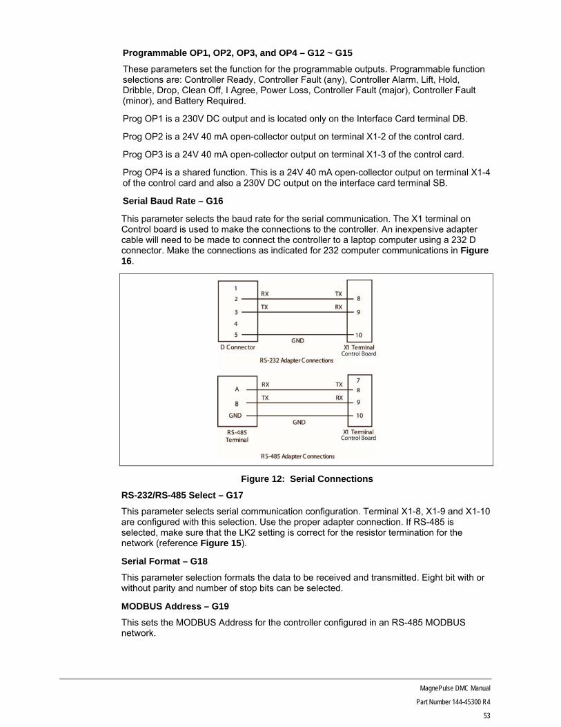
Serial Baud Rate – G16
This parameter selects the baud rate for the serial communication. The X1 terminal on Control board is used to make the connections to the controller. An inexpensive adapter cable will need to be made to connect the controller to a laptop computer using a 232 D connector. Make the connections as indicated for 232 computer communications in Figure 16.
Figure 12: Serial Connections
RS-232/RS-485 Select – G17
This parameter selects serial communication configuration. Terminal X1-8, X1-9 and X1-10 are configured with this selection. Use the proper adapter connection. If RS-485 is selected, make sure that the LK2 setting is correct for the resistor termination for the network (reference Figure 15).
Serial Format – G18
This parameter selection formats the data to be received and transmitted. Eight bit with or without parity and number of stop bits can be selected.
MODBUS Address – G19
This sets the MODBUS Address for the controller configured in an RS-485 MODBUS network.
MagnePulse DMC Manual
Part Number 144-45300 R4
54
Drive Control – G20
This directs drive control to board I/O (Hwd-IO) or MODBUS RTU-1 Control (Serial COMM1). It is possible to change from serial communication to hardware I/O through the MODBUS parameter change. It is not possible to change from hardware I/O to serial communication unless the parameter is changed manually.
SPEED IP Function – G21
This parameter selects the special MagnePulse magnet control functions.
The OmniBeam function allows the user to select from one to four magnets to be powered by the controller. The SPEED 2 input enables Magnet 1, the SPEED 3 input enables Magnet 2, the SPEED 4 input enables Magnet 3, and the SPEED 5 input enables Magnet 4. To start a pick at least one magnet must be enabled when this feature is selected.
CAUTION Parameters F02, F05, F08 and F11 must be programmed properly to prevent magnet damage. Do not enable additional magnets during operation. Magnets must be of sufficiently similar inductance and current rating to prevent individual magnet overload.
The Stepped I function allows for picking and dropping discrete loads. The FORWARD input enables Lift Current 1 and the REVERSE input enables Clean Current 1. Each successive SPEED input enables the successive current command.
Reset IP Function – G22
This parameter allows the reset switch to be used as a fault reset. If the use of this function is desired, make sure LK 3 is in the correct position (reference Figure 15).
Maintain Clean IP – G23
When enabled, this parameter will stop the clean cycle if the clean/drop input is opened.
If disabled, this parameter will allow a momentary clean/drop switch to complete the clean time (E07). A lift command engaged during the clean cycle will take the drive out of the clean state.
Enable IP Function – G25
This parameter allows the input signal to properly regulate the drive. If Drive Enable is selected, the drive requires the enable input to be active in order to enter the lift sequence.
Battery Enabled is selected when a battery back-up is used. Enabling this will prevent SC faults while the drive and battery are on at the same time.
MagnePulse DMC Manual
Part Number 144-45300 R4
55
Group H: Fault History
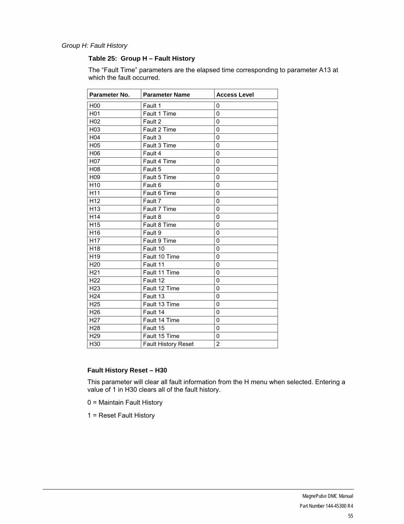
Table 25: Group H – Fault History
The “Fault Time” parameters are the elapsed time corresponding to parameter A13 at which the fault occurred.
Parameter No. Parameter Name Access Level
H00 Fault 1 0 H01 Fault 1 Time 0 H02 Fault 2 0 H03 Fault 2 Time 0 H04 Fault 3 0 H05 Fault 3 Time 0 H06 Fault 4 0 H07 Fault 4 Time 0 H08 Fault 5 0 H09 Fault 5 Time 0 H10 Fault 6 0 H11 Fault 6 Time 0 H12 Fault 7 0 H13 Fault 7 Time 0 H14 Fault 8 0 H15 Fault 8 Time 0 H16 Fault 9 0 H17 Fault 9 Time 0 H18 Fault 10 0 H19 Fault 10 Time 0 H20 Fault 11 0 H21 Fault 11 Time 0 H22 Fault 12 0 H23 Fault 12 Time 0 H24 Fault 13 0 H25 Fault 13 Time 0 H26 Fault 14 0 H27 Fault 14 Time 0 H28 Fault 15 0 H29 Fault 15 Time 0 H30 Fault History Reset 2
Fault History Reset – H30
This parameter will clear all fault information from the H menu when selected. Entering a value of 1 in H30 clears all of the fault history.
0 = Maintain Fault History
1 = Reset Fault History
MagnePulse DMC Manual
Part Number 144-45300 R4
56
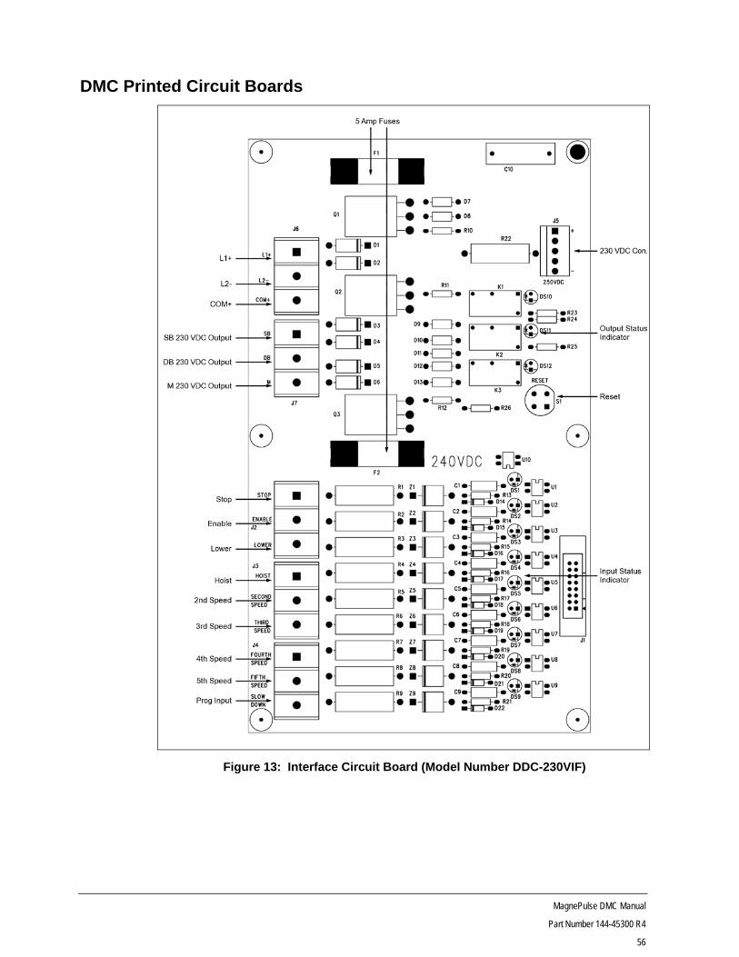
DMC Printed Circuit Boards
Figure 13: Interface Circuit Board (Model Number DDC-230VIF)

MagnePulse DMC Manual
Part Number 144-45300 R4
57
Figure 14: 120 VAC Interface Board (Model Number DMC-120A60IF)

MagnePulse DMC Manual
Part Number 144-45300 R4
58
Figure 15: Control Card (Model Number DMC-CONTROL)
LK2
For RS-485 communication, the link should be on pins 1 and 2 (top pins).
LK3
If the link is on pins 1 and 2 and parameter G22 is not disabled, the RESET input will act as a fault reset only. Place the link on pins 2 and 3 if a drive reset is intended.

MagnePulse DMC Manual
Part Number 144-45300 R4
59
Table 26: Control Board S2 DIP Switch Settings
SW POS OFF (OPEN) ON (CLOSED)
A AN1 -10/+10V
AN1 4/20 mA
B AN1 Diff
AN1 Non Diff
C AN1 X1
AN1 X2
D AN2 0/+10V
AN2 4/20 mA
Table 27: Control Board S1 DIP Switch Settings
S1 Positions 1 and 2 — Current Rating
Current Class Switch Setting
N2 67A S1–1 OFF S1–2 OFF
N3 133A S1–1 ON S1–2 OFF
N4 200A S1–1 OFF S1–2 ON
N5 400A S1–1 ON S1–2 ON SW1 Position 4 — Voltage Rating
Voltage Class Switch Setting
200/360V S1–4 OFF
400/720V S1–4 ON
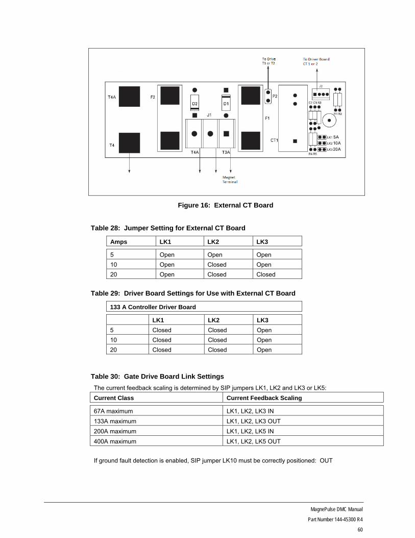
MagnePulse DMC Manual
Part Number 144-45300 R4
60
Figure 16: External CT Board
Table 28: Jumper Setting for External CT Board
Amps LK1 LK2 LK3
5 Open Open Open
10 Open Closed Open
20 Open Closed Closed
Table 29: Driver Board Settings for Use with External CT Board
133 A Controller Driver Board
LK1 LK2 LK3
5 Closed Closed Open
10 Closed Closed Open
20 Closed Closed Open
Table 30: Gate Drive Board Link Settings
The current feedback scaling is determined by SIP jumpers LK1, LK2 and LK3 or LK5:
Current Class Current Feedback Scaling
67A maximum LK1, LK2, LK3 IN
133A maximum LK1, LK2, LK3 OUT
200A maximum LK1, LK2, LK5 IN
400A maximum LK1, LK2, LK5 OUT
If ground fault detection is enabled, SIP jumper LK10 must be correctly positioned: OUT

MagnePulse DMC Manual
Part Number 144-45300 R4
61
Figure 17: Driver Board (used on 200/320 VDC 133A) Model Number DDC-LN3-GATE
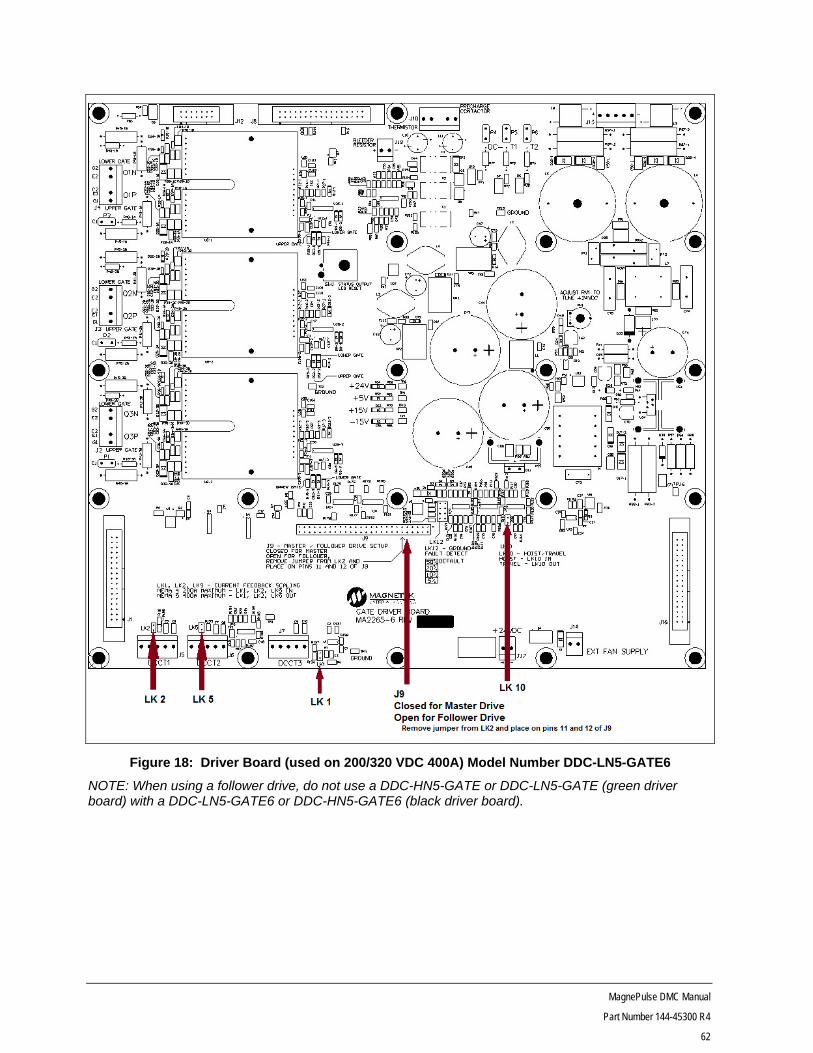
MagnePulse DMC Manual
Part Number 144-45300 R4
62
Figure 18: Driver Board (used on 200/320 VDC 400A) Model Number DDC-LN5-GATE6
NOTE: When using a follower drive, do not use a DDC-HN5-GATE or DDC-LN5-GATE (green driver board) with a DDC-LN5-GATE6 or DDC-HN5-GATE6 (black driver board).
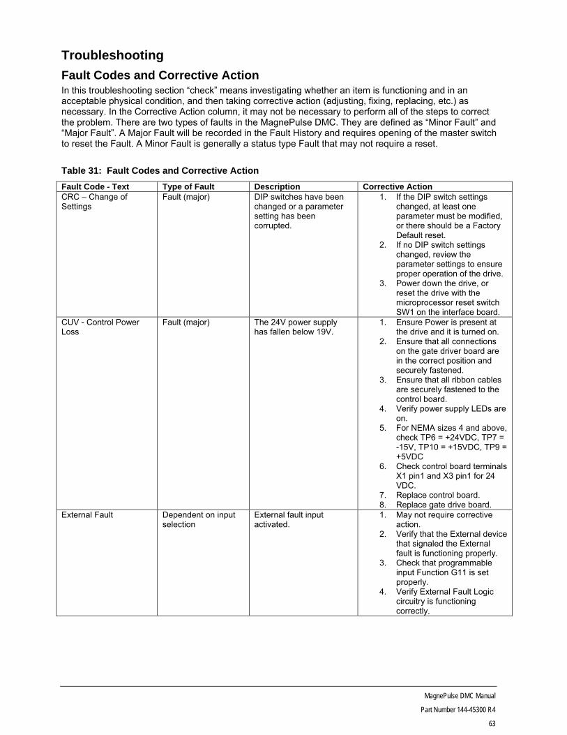
MagnePulse DMC Manual
Part Number 144-45300 R4
63
Troubleshooting
Fault Codes and Corrective Action In this troubleshooting section “check” means investigating whether an item is functioning and in an acceptable physical condition, and then taking corrective action (adjusting, fixing, replacing, etc.) as necessary. In the Corrective Action column, it may not be necessary to perform all of the steps to correct the problem. There are two types of faults in the MagnePulse DMC. They are defined as “Minor Fault” and “Major Fault”. A Major Fault will be recorded in the Fault History and requires opening of the master switch to reset the Fault. A Minor Fault is generally a status type Fault that may not require a reset.
Table 31: Fault Codes and Corrective Action
Fault Code - Text Type of Fault Description Corrective Action CRC – Change of Settings
Fault (major) DIP switches have been changed or a parameter setting has been corrupted.
1. If the DIP switch settings changed, at least one parameter must be modified, or there should be a Factory Default reset.
2. If no DIP switch settings changed, review the parameter settings to ensure proper operation of the drive.
3. Power down the drive, or reset the drive with the microprocessor reset switch SW1 on the interface board.
CUV - Control Power Loss
Fault (major) The 24V power supply has fallen below 19V.
1. Ensure Power is present at the drive and it is turned on.
2. Ensure that all connections on the gate driver board are in the correct position and securely fastened.
3. Ensure that all ribbon cables are securely fastened to the control board.
4. Verify power supply LEDs are on.
5. For NEMA sizes 4 and above, check TP6 = +24VDC, TP7 = -15V, TP10 = +15VDC, TP9 = +5VDC
6. Check control board terminals X1 pin1 and X3 pin1 for 24 VDC.
7. Replace control board. 8. Replace gate drive board.
External Fault Dependent on input selection
External fault input activated.
1. May not require corrective action.
2. Verify that the External device that signaled the External fault is functioning properly.
3. Check that programmable input Function G11 is set properly.
4. Verify External Fault Logic circuitry is functioning correctly.

MagnePulse DMC Manual
Part Number 144-45300 R4
64
Fault Code - Text Type of Fault Description Corrective Action Ground Fault Fault (minor) A Ground Fault has been
detected. 1. Check the magnet circuit for
shorts to ground. 2. Check that displayed Magnet
Current Function A00 equals Actual Magnet Current using a clamp on amp meter.
3. Check for a short circuit in the magnet or wiring using a Megger. Ensure that the magnet is disconnected from the control.
MOC – Magnet Open Circuit
Fault (major) Indicates that the magnet coil is open or that current is not passing from control terminals T1 to T2.
1. Monitor A00 for Magnet current feedback.
2. Check magnet circuit and wiring.
3. Perform Diode and IGBT test per Transistor and Diode Check Table.
MOL – Magnet Overload
Fault (minor) Indicates the control board is not regulating current to the magnet properly and the magnet may be overloaded.
1. Check DIP switch settings on the control board.
2. Check magnet current rating parameters.
3. Check for correct gate driver board link settings.
MOS – Module out of Service
Fault (major) Indicates that one or more follower units are out of service.
1. Verify the setting in parameter C03.
2. Ensure that follower controller is powered up correctly.
3. Ensure that the gate drive board data bus able is connected between master and follower(s) (J1 and J16).
4. Verify on follower(s) gate drive board that bus connecter J9 has only pins 11 and 12 jumpered.
MS - Master Switch
Alarm Drive inputs not in OFF position when drive powered up.
1. Is the master switch centered?
2. Ensure input logic wiring is functioning correctly.
3. Check that Logic Inputs on Function A21 are functioning properly.
4. Check that programmable input Function G11 is set properly.
AOT– Over Ambient Fault (minor) The ambient temperature monitored by the control board is 70° C or greater.
1. Monitor ambient temperature by A24.
2. Decrease ambient temperature.
3. Ensure that fans are functional.
4. Ensure heatsink is free of dirt and debris.
5. Add air conditioner.
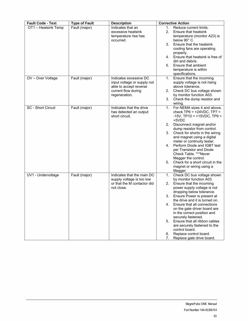
MagnePulse DMC Manual
Part Number 144-45300 R4
65
Fault Code - Text Type of Fault Description Corrective Action OT1 – Heatsink Temp Fault (major) Indicates that an
excessive heatsink temperature rise has occurred.
1. Reduce current limits. 2. Ensure that heatsink
temperature (monitor A23) is below 90° C.
3. Ensure that the heatsink cooling fans are operating properly.
4. Ensure that heatsink is free of dirt and debris.
5. Ensure that ambient temperature is within specifications.
OV – Over Voltage Fault (major) Indicates excessive DC input voltage or supply not able to accept reverse current flow during regeneration.
1. Ensure that the incoming supply voltage is not rising above tolerance.
2. Check DC bus voltage shown by monitor function A03.
3. Check the dump resistor and wiring.
SC - Short Circuit Fault (major) Indicates that the drive has detected an output short circuit.
1. For NEMA sizes 4 and above, check TP6 = +24VDC, TP7 = -15V, TP10 = +15VDC, TP9 = +5VDC
2. Disconnect magnet and/or dump resistor from control.
3. Check for shorts in the wiring and magnet using a digital meter or continuity tester.
4. Perform Diode and IGBT test per Transistor and Diode Check Table. ***Never Megger the control.
5. Check for a short circuit in the magnet or wiring using a Megger.
UV1 - Undervoltage
Fault (major) Indicates that the main DC supply voltage is too low or that the M contactor did not close.
1. Check DC bus voltage shown by monitor function A03.
2. Ensure that the incoming power supply voltage is not dropping below tolerance.
3. Ensure Power is present at the drive and it is turned on.
4. Ensure that all connections on the gate driver board are in the correct position and securely fastened.
5. Ensure that all ribbon cables are securely fastened to the control board.
6. Replace control board. 7. Replace gate drive board.

MagnePulse DMC Manual
Part Number 144-45300 R4
66
Short Circuit Check When a short circuit occurs, the Gate Driver Board (DDC-LN5-GATE6 or DDC-HN5-GATE6) can be used as a troubleshooting tool to narrow down where the short is located. This is especially helpful when there are multiple follower drives. Each drive (master and follower) has the same Gate Driver Board that will notify the user with LEDs if a short has occurred on that individual drive. To help further, there are two LEDs designated to show if the short occurred on the upper or lower gate for each IGBT.
Figure 19: Gate Driver LED locations

MagnePulse DMC Manual
Part Number 144-45300 R4
67
Transistor and Diode Check
DANGER Make sure that the MCB or MKS and CCB or CKS are in the open position and that the charge light and control light on the control are off.
Using a digital multimeter set the instrument to the diode mode and make the following checks:
Table 32: Transistor and Diode Check
Diode Check Positive Probe Negative Probe Reading
D1P T1 L1 0.312
D2P T2 L1 0.312
D3P T3 L1 0.312
D1N L2 T1 0.312
D2N L2 T2 0.312
D3N L2 T3 0.312
IGBT Check Positive Probe Negative Probe Reading
Q1P L1 T1 >0.6
Q2P L1 T2 >0.6
Q3P L1 T3 >0.6
Q1N T1 L2 >0.6
Q2N T2 L2 >0.6
Q3N T3 L2 >0.6
On the 400A and high voltage controls use the IGBT auxiliary connection. Remove the connectors from P1, P2 and P3 on the 144-45059 driver board and do a continuity check from the connector wire to T4 terminal. Typical measurement is about 0.3 ohms. Replace the IGBT if the reading is open.
Note: If BUS fuse is open, IGBT check will indicate that all transistors are opened. Check BUS fuse before taking readings.
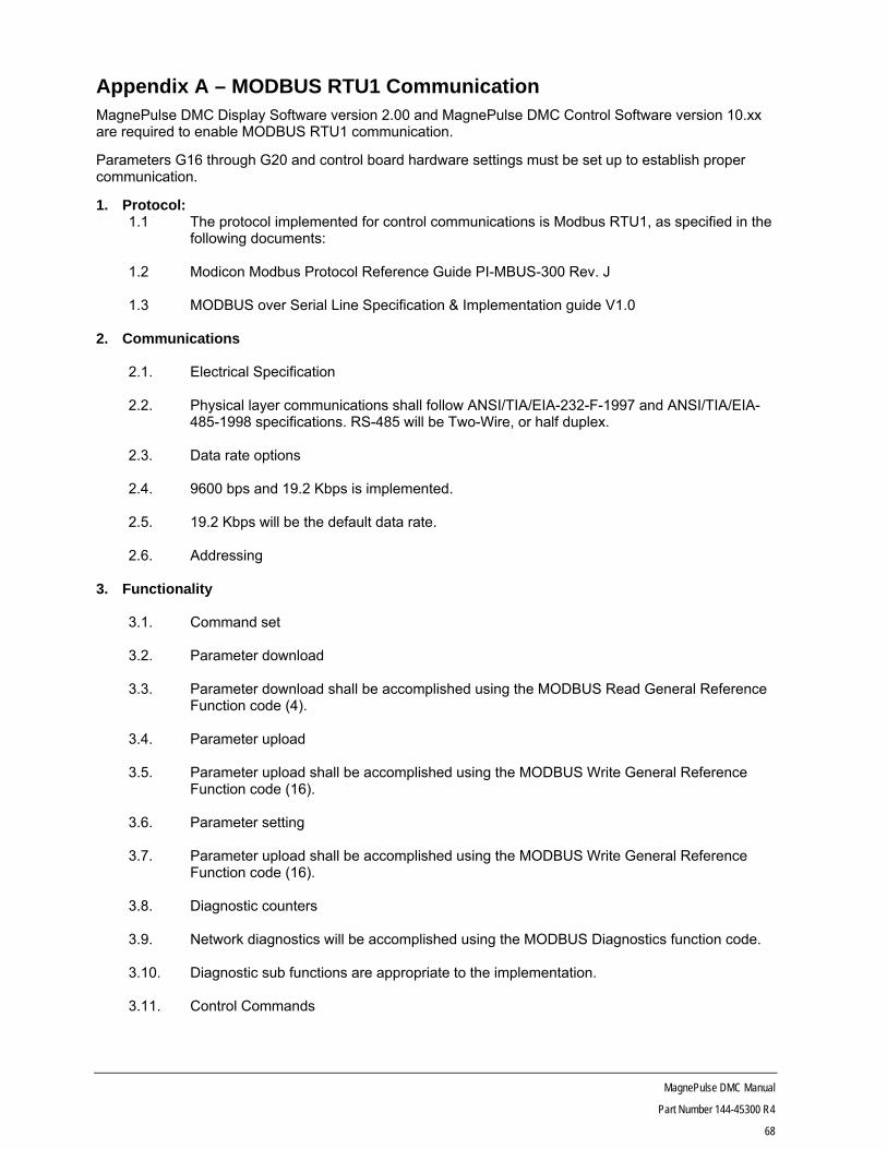
MagnePulse DMC Manual
Part Number 144-45300 R4
68
Appendix A – MODBUS RTU1 Communication MagnePulse DMC Display Software version 2.00 and MagnePulse DMC Control Software version 10.xx are required to enable MODBUS RTU1 communication.
Parameters G16 through G20 and control board hardware settings must be set up to establish proper communication.
1. Protocol: 1.1 The protocol implemented for control communications is Modbus RTU1, as specified in the
following documents:
1.2 Modicon Modbus Protocol Reference Guide PI-MBUS-300 Rev. J
1.3 MODBUS over Serial Line Specification & Implementation guide V1.0
2. Communications
2.1. Electrical Specification 2.2. Physical layer communications shall follow ANSI/TIA/EIA-232-F-1997 and ANSI/TIA/EIA-
485-1998 specifications. RS-485 will be Two-Wire, or half duplex. 2.3. Data rate options 2.4. 9600 bps and 19.2 Kbps is implemented. 2.5. 19.2 Kbps will be the default data rate. 2.6. Addressing
3. Functionality
3.1. Command set 3.2. Parameter download 3.3. Parameter download shall be accomplished using the MODBUS Read General Reference
Function code (4). 3.4. Parameter upload 3.5. Parameter upload shall be accomplished using the MODBUS Write General Reference
Function code (16). 3.6. Parameter setting 3.7. Parameter upload shall be accomplished using the MODBUS Write General Reference
Function code (16). 3.8. Diagnostic counters 3.9. Network diagnostics will be accomplished using the MODBUS Diagnostics function code. 3.10. Diagnostic sub functions are appropriate to the implementation. 3.11. Control Commands

MagnePulse DMC Manual
Part Number 144-45300 R4
69
3.12. Network direction control will be accomplished using the MODBUS Force Single Coil Function code (5) for writing, and Read Coil Status function code (1) for verification.
3.13. Network Run/Stop control will be accomplished using the MODBUS Force Single Coil
Function code (5) for writing, and Read Coil Status function code (1) for verification. 3.14. Network discrete Speed Reference control will be accomplished using the MODBUS
Force Single Coil Function code (5) for writing, and Read Coil Status function code (1) for verification.
3.15. Network analog Speed Reference control will be accomplished using the MODBUS Preset
Single Register Function code (6) for writing, and Read Holding Register function code (3) for verification.
3.16. Parameter read and write access is limited to 10 values at the time in order to maintain
control loop functionality.
4. Addressing
4.1 Parameter Download (Read General Reference Function code (20)) and Upload and Setting (Write General Reference Function code (16)).
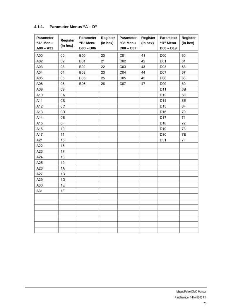
MagnePulse DMC Manual
Part Number 144-45300 R4
70
4.1.1. Parameter Menus “A – D”
Parameter
“A” Menu
A00 – A31
Register
(in hex)
Parameter
“B” Menu
B00 – B06
Register
(in hex)
Parameter
“C” Menu
C00 – C07
Register
(in hex)
Parameter
“D” Menu
D00 – D19
Register
(in hex)
A00 00 B00 20 C01 41 D00 60
A02 02 B01 21 C02 42 D01 61
A03 03 B02 22 C03 43 D03 63
A04 04 B03 23 C04 44 D07 67
A05 05 B05 25 C05 45 D08 68
A08 08 B06 26 C07 47 D09 69
A09 09 D11 6B
A10 0A D12 6C
A11 0B D14 6E
A12 0C D15 6F
A13 0D D16 70
A14 0E D17 71
A15 0F D18 72
A16 10 D19 73
A17 11 D30 7E
A21 15 D31 7F
A22 16
A23 17
A24 18
A25 19
A26 1A
A27 1B
A29 1D
A30 1E
A31 1F

MagnePulse DMC Manual
Part Number 144-45300 R4
71
4.1.2. Parameter Menus “E – H“
Parameter
“E” Menu
E00 – E23
Register
(in hex)
Parameter
“F” Menu
F00 – F13
Register
(in hex)
Parameter
“G” Menu
G00 – G25
Register
(in hex)
Parameter
“H” Menu
H00 – H30
Register
(in hex)
E00 80 F00 A0 G00 C0 H00 E0
E01 81 F02 A2 G01 C1 H01 E1
E02 82 F03 A3 G02 C2 H02 E2
E03 83 F04 A4 G04 C4 H03 E3
E04 84 F05 A5 G05 C5 H04 E4
E05 85 F06 A6 G06 C6 H05 E5
E06 86 F07 A7 G08 C8 H06 E6
E07 87 F08 A8 G09 C9 H07 E7
E08 88 F09 A9 G10 CA H08 E8
E09 89 F10 AA G11 CB H09 E9
E10 8A F11 AB G12 CC H10 EA
E11 8B F12 AC G13 CD H11 EB
E12 8C F13 AD G14 CE H12 EC
E13 8D G15 CF H13 ED
E14 8E G16 D0 H14 EE
E15 8F G17 D1 H15 EF
E16 90 G18 D2 H16 E0
E17 91 G19 D3 H17 F1
E18 92 G20 D4 H18 F2
E20 94 G21 D5 H19 F3
E21 95 G22 D6 H20 F4
E22 96 G23 D7 H21 F5
E23 97 G25 D9 H22 F6
H23 F7
H24 F8
H25 F9
H26 FA
H27 FB
H28 FC
H29 FD
H30 FE
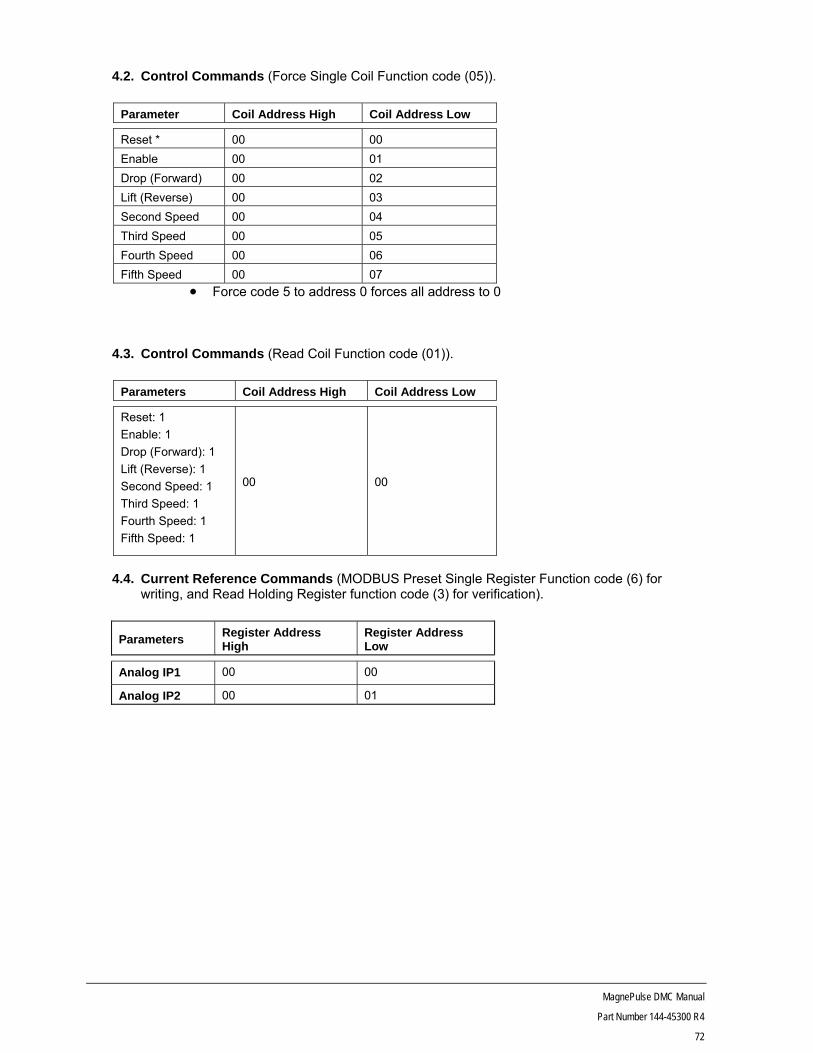
MagnePulse DMC Manual
Part Number 144-45300 R4
72
4.2. Control Commands (Force Single Coil Function code (05)).
Parameter Coil Address High Coil Address Low
Reset * 00 00
Enable 00 01
Drop (Forward) 00 02
Lift (Reverse) 00 03
Second Speed 00 04
Third Speed 00 05
Fourth Speed 00 06
Fifth Speed 00 07
Force code 5 to address 0 forces all address to 0
4.3. Control Commands (Read Coil Function code (01)).
Parameters Coil Address High Coil Address Low
Reset: 1
Enable: 1
Drop (Forward): 1
Lift (Reverse): 1
Second Speed: 1
Third Speed: 1
Fourth Speed: 1
Fifth Speed: 1
00
00
4.4. Current Reference Commands (MODBUS Preset Single Register Function code (6) for
writing, and Read Holding Register function code (3) for verification).
Parameters Register Address High
Register Address Low
Analog IP1 00 00
Analog IP2 00 01
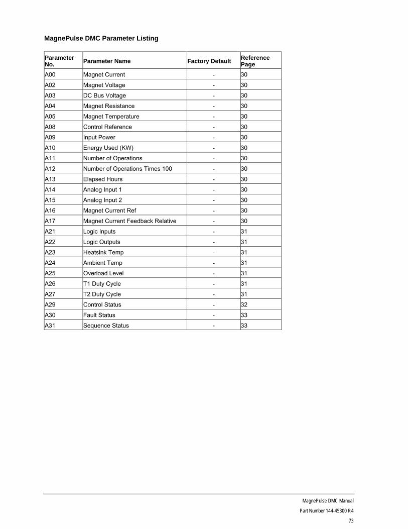
MagnePulse DMC Manual
Part Number 144-45300 R4
73
MagnePulse DMC Parameter Listing
Parameter No. Parameter Name Factory Default Reference
Page
A00 Magnet Current - 30
A02 Magnet Voltage - 30
A03 DC Bus Voltage - 30
A04 Magnet Resistance - 30
A05 Magnet Temperature - 30
A08 Control Reference - 30
A09 Input Power - 30
A10 Energy Used (KW) - 30
A11 Number of Operations - 30
A12 Number of Operations Times 100 - 30
A13 Elapsed Hours - 30
A14 Analog Input 1 - 30
A15 Analog Input 2 - 30
A16 Magnet Current Ref - 30
A17 Magnet Current Feedback Relative - 30
A21 Logic Inputs - 31
A22 Logic Outputs - 31
A23 Heatsink Temp - 31
A24 Ambient Temp - 31
A25 Overload Level - 31
A26 T1 Duty Cycle - 31
A27 T2 Duty Cycle - 31
A29 Control Status - 32
A30 Fault Status - 33
A31 Sequence Status - 33
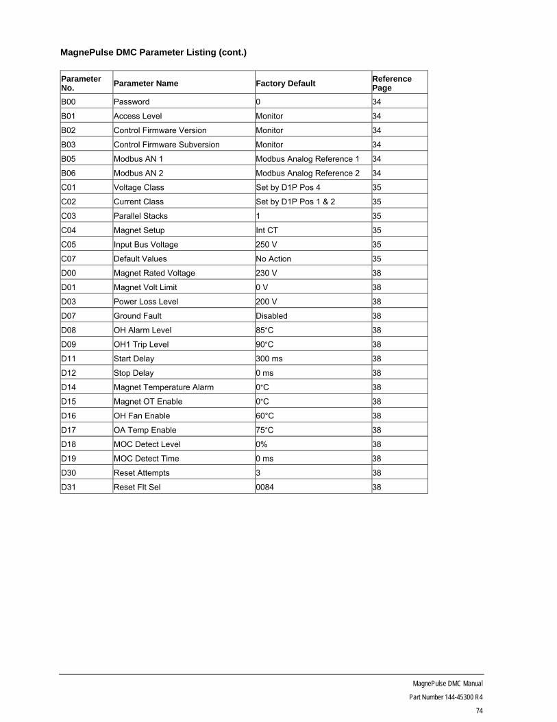
MagnePulse DMC Manual
Part Number 144-45300 R4
74
MagnePulse DMC Parameter Listing (cont.)
Parameter No. Parameter Name Factory Default Reference
Page
B00 Password 0 34
B01 Access Level Monitor 34
B02 Control Firmware Version Monitor 34
B03 Control Firmware Subversion Monitor 34
B05 Modbus AN 1 Modbus Analog Reference 1 34
B06 Modbus AN 2 Modbus Analog Reference 2 34
C01 Voltage Class Set by D1P Pos 4 35
C02 Current Class Set by D1P Pos 1 & 2 35
C03 Parallel Stacks 1 35
C04 Magnet Setup Int CT 35
C05 Input Bus Voltage 250 V 35
C07 Default Values No Action 35
D00 Magnet Rated Voltage 230 V 38
D01 Magnet Volt Limit 0 V 38
D03 Power Loss Level 200 V 38
D07 Ground Fault Disabled 38
D08 OH Alarm Level 85°C 38
D09 OH1 Trip Level 90°C 38
D11 Start Delay 300 ms 38
D12 Stop Delay 0 ms 38
D14 Magnet Temperature Alarm 0°C 38
D15 Magnet OT Enable 0°C 38
D16 OH Fan Enable 60°C 38
D17 OA Temp Enable 75°C 38
D18 MOC Detect Level 0% 38
D19 MOC Detect Time 0 ms 38
D30 Reset Attempts 3 38
D31 Reset Flt Sel 0084 38

MagnePulse DMC Manual
Part Number 144-45300 R4
75
MagnePulse DMC Parameter Listing (cont.)
Parameter No. Parameter Name Factory Default Reference
Page
E00 Lift Current 100.0% 42
E01 Hold Current 75.0% 42
E02 Dribble Current -10.0% 42
E03 Clean Current 15.0% 42
E04 Cast Rate 1%/s 42
E05 Lift Time 15.0 s 42
E06 Dribble Rate 2%/s 42
E07 Clean Time 0.8 s 42
E08 Decreased Lift 10% 42
E09 Lift Current 1 100% 42
E10 Lift Current 2 80% 42
E11 Lift Current 3 60% 42
E12 Lift Current 4 40% 42
E13 Lift Current 5 20% 42
E14 Clean Current 1 20% 42
E15 Clean Current 2 40% 42
E16 Clean Current 3 60% 42
E17 Clean Current 4 80% 42
E18 Clean Current 5 100% 42
E20 I Agree 1.5% 43
E21 P Gain 1.0 43
E22 I Gain 0.2 43
E23 Auto Clean Disabled 43

MagnePulse DMC Manual
Part Number 144-45300 R4
76
MagnePulse DMC Parameter Listing (cont.)
Parameter No.
Parameter Name Factory Default Reference Page
F00 Current Reference Source Cntr Switch 48
F02 Magnet 1 Current C02/2 48
F03 Magnet 1 Inductance Gain 2.0 48
F04 Magnet 1 Resistance 4.00 48
F05 Magnet 2 Current 0 48
F06 Magnet 2 Inductance Gain 2.0 48
F07 Magnet 2 Resistance 4.00 48
F08 Magnet 3 Current 0 48
F09 Magnet 3 Inductance Gain 2.0 48
F10 Magnet 3 Resistance 4.00 48
F11 Magnet 4 Current 0 48
F12 Magnet 4 Inductance Gain 2.0 48
F13 Magnet 4 Resistance 4.00 48
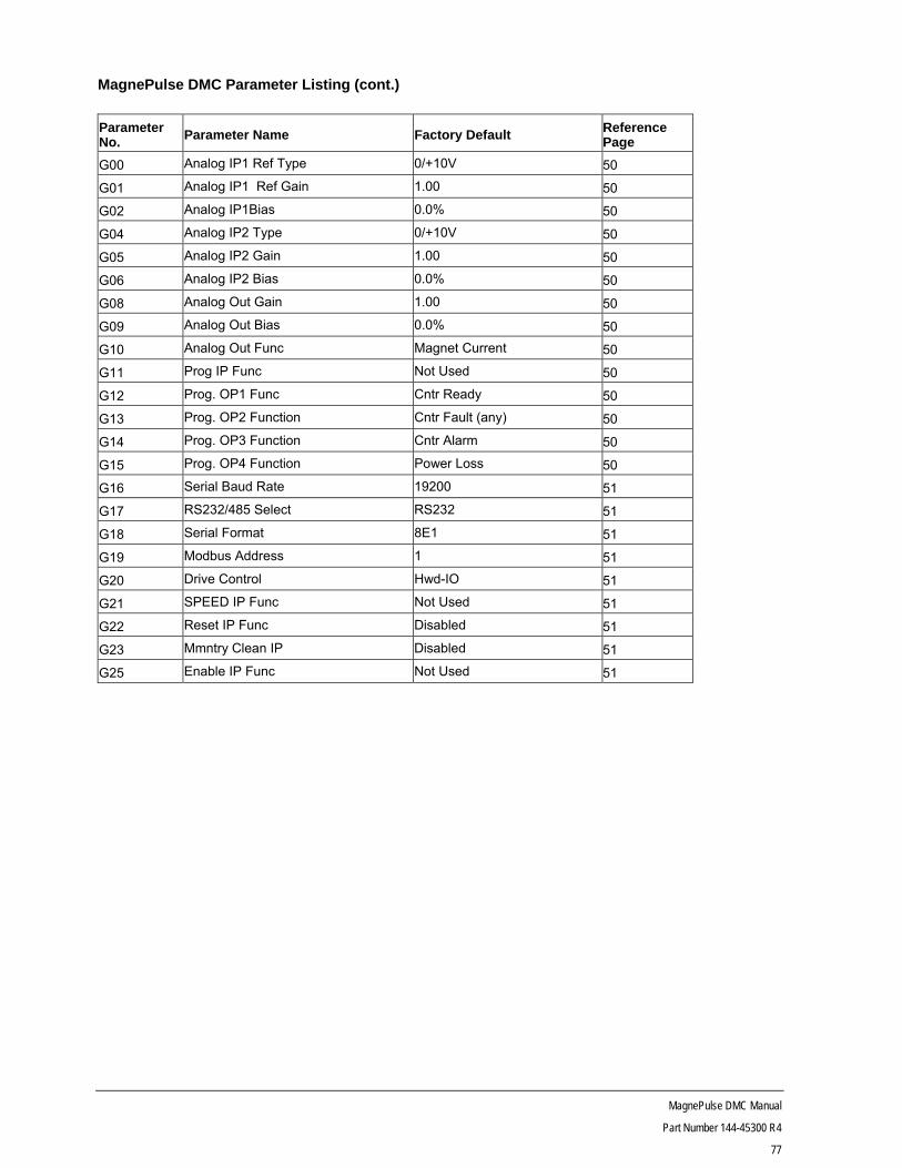
MagnePulse DMC Manual
Part Number 144-45300 R4
77
MagnePulse DMC Parameter Listing (cont.)
Parameter No. Parameter Name Factory Default Reference
Page
G00 Analog IP1 Ref Type 0/+10V 50
G01 Analog IP1 Ref Gain 1.00 50
G02 Analog IP1Bias 0.0% 50
G04 Analog IP2 Type 0/+10V 50
G05 Analog IP2 Gain 1.00 50
G06 Analog IP2 Bias 0.0% 50
G08 Analog Out Gain 1.00 50
G09 Analog Out Bias 0.0% 50
G10 Analog Out Func Magnet Current 50
G11 Prog IP Func Not Used 50
G12 Prog. OP1 Func Cntr Ready 50
G13 Prog. OP2 Function Cntr Fault (any) 50
G14 Prog. OP3 Function Cntr Alarm 50
G15 Prog. OP4 Function Power Loss 50
G16 Serial Baud Rate 19200 51
G17 RS232/485 Select RS232 51
G18 Serial Format 8E1 51
G19 Modbus Address 1 51
G20 Drive Control Hwd-IO 51
G21 SPEED IP Func Not Used 51
G22 Reset IP Func Disabled 51
G23 Mmntry Clean IP Disabled 51
G25 Enable IP Func Not Used 51

MagnePulse DMC Manual
Part Number 144-45300 R4
78
MagnePulse DMC Parameter Listing (cont.)
Parameter No. Parameter Name Factory Default Reference
Page
H00 Fault 1 - 55
H01 Fault 1 Time (Hours) - 55
H02 Fault 2 - 55
H03 Fault 2 Time (Hours) - 55
H04 Fault 3 - 55
H05 Fault 3 Time (Hours) - 55
H06 Fault 4 - 55
H07 Fault 4 Time (Hours) - 55
H08 Fault 5 - 55
H09 Fault 5 Time (Hours) - 55
H10 Fault 6 - 55
H11 Fault 6 Time (Hours) - 55
H12 Fault 7 - 55
H13 Fault 7 Time (Hours) - 55
H14 Fault 8 - 55
H15 Fault 8 Time (Hours) - 55
H16 Fault 9 - 55
H17 Fault 9 Time (Hours) - 55
H18 Fault 10 - 55
H19 Fault 10 Time (Hours) - 55
H20 Fault 11 - 55
H21 Fault 11 Time (Hours) - 55
H22 Fault 12 - 55
H23 Fault 12 Time (Hours) - 55
H24 Fault 13 - 55
H25 Fault 13 Time (Hours) - 55
H26 Fault 14 - 55
H27 Fault 14 Time (Hours) - 55
H28 Fault 15 - 55
H29 Fault 15 Time (Hours) - 55
H30 Fault Hist. Reset - 55