1438sac - beta-tools.comsac... · instrukcja obsŁugi 1438sac. 2 1438sac componenti - components -...
TRANSCRIPT

P
PL
NL
D
INSTRUCCIONESGEBRUIKSAANWIJZING
E
HU HASZNÁLATI ÚTMUTATÓ
I
EN
F
ISTRUZIONI PER L’USOINSTRUCTIONS FOR USEMODE D’EMPLOIGEBRAUCHSANWEISUNG
INSTRUÇÕES DE USOINSTRUKCJA OBSŁUGI
1438SAC

2
1438SACCOMPONENTI - COMPONENTS - COMPOSANTS - BESTANDTEILE - COMPONENTES -
ONDERDELEN - KOMPONENTY - COMPONENTES - KOMPONENSEK
VN943
VN944
VN945
VN946VN947
VN952VN954
VN953VN948
VN955
VN956
VN949
VN950VN951
VN942
VN941
VN937 VN936 VN935 VN934 VN933 VN932 VN931 VN930+
M8x45
VN926
VN927
VN928
VN929
VN939
VN922
VN920
VN938
VN938
VN923
VN924
VN925
VN921
3
ISTRUZIONI PER L’USO I
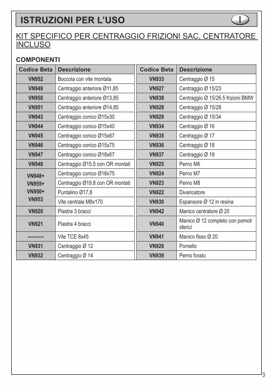
KIT SPECIFICO PER CENTRAGGIO FRIZIONI SAC, CENTRATORE INCLUSO
COMPONENTICodice Beta Descrizione Codice Beta Descrizione
VN952 Boccola con vite montata VN933 Centraggio Ø 15VN949 Centraggio anteriore Ø11,85 VN927 Centraggio Ø 15/23VN950 Centraggio anteriore Ø13,85 VN938 Centraggio Ø 15/26.5 frizioni BMWVN951 Centraggio anteriore Ø14,85 VN928 Centraggio Ø 15/28VN943 Centraggio conico Ø15x30 VN929 Centraggio Ø 15/34VN944 Centraggio conico Ø15x40 VN934 Centraggio Ø 16VN945 Centraggio conico Ø15x67 VN935 Centraggio Ø 17VN946 Centraggio conico Ø15x75 VN936 Centraggio Ø 18VN947 Centraggio conico Ø18x67 VN937 Centraggio Ø 19VN948 Centraggio Ø15,5 con OR montati VN925 Perno M6
VN948+VN955+VN956+VN953
Centraggio conico Ø18x75 VN924 Perno M7Centraggio Ø19,8 con OR montati VN923 Perno M8Puntalino Ø17,8 VN922 DivaricatoreVite centrale M8x170 VN930 Espansore Ø 12 in resina
VN920 Piastra 3 bracci VN942 Manico centratore Ø 20
VN921 Piastra 4 bracci VN940 Manico Ø 12 completo con pomoli sferici
---------- Vite TCE 8x45 VN941 Manico fisso Ø 20VN931 Centraggio Ø 12 VN926 PomelloVN932 Centraggio Ø 14 VN939 Perno forato

4
ISTRUZIONI PER L’USO I
Oggigiorno sempre più autovetture montano le frizioni denominate SAC (Self Adju-sting Clutch), di seguito vengono riportati alcuni modelli:
Marca ModelloAlfa romeo 147 - 159 - 166 - Brera - SpiderAudi A3 - A4 - A6 - A8 - TTBmw 320 - 330 - 520 - 530Citroën C-CrosserFiat Ulisse - Croma - Ducato - Bravo - StiloFord Mondeo - Galaxy - Transit - S-Max - Focus C-MaxHyundai H-1 - I30 - Santa Fè - Sonata - TusconLancia Delta - Thesis - PhedraMercedes C - E - CLS - S - CLK - SLK - SLMitsubishi Grandis - OutlanderOpel VivaroPeugeot 4007Renault Espace IV - Laguna - Laguna II - Laguna III - Trafic II - Vel SatisSeat Altea - Leon - Toledo IISkoda Octavia - SuperbVauxhall Vivaro
Volkswagen Eos - Golf IV - Golf V - Golf V Plus - Jetta II - Multivan T5 - Passat - Passat CC - Scirocco - Touran - Transporter V
Volvo Volvo S40 II - V50
APPLICAZIONE:Tali frizioni sono definite autoregistranti, in quanto, tramite un meccanismo di regola-zione automatica, tendono a compensare il gioco crescente che si crea a causa dell’usura del disco della frizione.
Tale dispositivo, garantisce una forza di di-sinnesto costante nel tempo e questo, oltre a incrementare il comfort, allunga di molto la vita della frizione.
Le frizioni SAC si riconoscono per la presenza di 2 o 3 mollette gialle presenti sul meccanismo

5
È necessario porre molta attenzione du-rante il montaggio di tali frizioni, in quanto un montaggio scorretto potrebbe causare deformazioni della campana del meccani-smo frizione o un perdita di regolazione dello stesso.
Questo comporta la difficoltà di riconoscere in garan-zia pezzi il cui malfunzionamento è implicabile a errori di montaggio.
Per evitare tali inconvenienti, il corretto montaggio e smontaggio di tali frizioni SAC, deve avvenire con l’utilizzo di un attrezzo speciale.
SMONTAGGIO:È assolutamente necessario l’uso di questa attrezzatura speciale per smontare le frizioni auto regolabili (SAC).Se infatti, provassimo a smontare una frizione SAC senza tale attrezzo, la frizione perderebbe la sua regolazione e causerebbe problemi di funzionamento durante il suo rimontaggio.
Seguire le seguenti istruzioni:● Montare il manico come nella figura 1.● Svitare dal meccanismo le 3 viti a 120° (o 4 viti a 90°, fig. 2).● Montare le viti corrispondenti M6, M7 o M8 (distanziali) in
dotazione (fig. 3 e 4).● Installare l’attrezzo speciale di fissaggio (3 o 4 bracci) e
fissarlo i dadi M8.● Ruotare il manico dell’attrezzo speciale per fissare
completamente il coperchio copri molla (fig. 5).● Svitare ore le altre viti di fissaggio del volano (fig. 6).● Rimuovere i dadi M8 dall’attrezzo speciale e, sucessivamente, l’attrezzo speciale e i 3 distanziali.● Ora si può sollevare il piatto spingidisco, la campana del meccanismo frizione è a battuta sul volano, questo facilita la rimozione della frizione (fig. 7).
1
2
3
4
5
6

6
MONTAGGIO:
● Appoggiare disco e meccanismo frizione al volano.● Centrare il disco frizione tramite l’apposito attrezzo dato in dotazione (fig. 8 - 9 - 10 - 11).● Inserire le tre viti (distanziali) senza serrarli perché questo comportare il danneggiamento del meccanismo SAC.● Installare l’attrezzo speciale di bloccaggio e bloccarlo con i tre bulloni forniti in dotazione. Si noti come la campana del meccanismo frizione non sia più in contatto con il volano.● Ruotare il manico dell’attrezzo speciale per fissare completamente la molla. Ora la campana è a battuta con il volano.● Collocare e avvitare le viti di fissaggio al volano.● Liberare l’attrezzo dalla pressione e rimuovere tutti i pezzi.● Montare le tre viti e finire l’operazione.
7
8
9
10
11
Spingidisco
Volano
Piatto
7
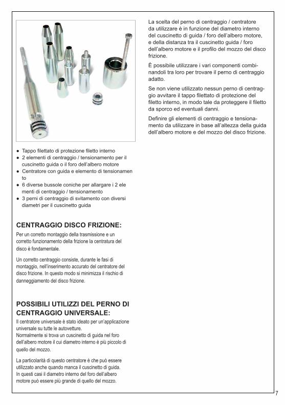
● Tappo filettato di protezione filetto interno● 2 elementi di centraggio / tensionamento per il cuscinetto guida o il foro dell’albero motore● Centratore con guida e elemento di tensionamen to● 6 diverse bussole coniche per allargare i 2 ele menti di centraggio / tensionamento● 3 perni di centraggio di svitamento con diversi diametri per il cuscinetto guida
CENTRAGGIO DISCO FRIZIONE:Per un corretto montaggio della trasmissione e uncorretto funzionamento della frizione la centratura deldisco è fondamentale.
Un corretto centraggio consiste, durante le fasi dimontaggio, nell’inserimento accurato del centratore deldisco frizione. In questo modo si minimizza il rischio didanneggiamento del disco frizione.
POSSIBILI UTILIZZI DEL PERNO DI CENTRAGGIO UNIVERSALE:Il centratore universale è stato ideato per un’applicazioneuniversale su tutte le autovetture.Normalmente si trova un cuscinetto di guida nel forodell’albero motore il cui diametro interno è più piccolo diquello del mozzo.
La particolarità di questo centratore è che può essereutilizzato anche quando manca il cuscinetto di guida.In questi casi il diametro interno del foro dell’alberomotore può essere più grande di quello del mozzo.
La scelta del perno di centraggio / centratore da utilizzare è in funzione del diametro interno del cuscinetto di guida / foro dell’albero motore, e della distanza tra il cuscinetto guida / foro dell’albero motore e il profilo del mozzo del disco frizione.
È possibile utilizzare i vari componenti combi-nandoli tra loro per trovare il perno di centraggio adatto.
Se non viene utilizzato nessun perno di centrag-gio avvitare il tappo filettato di protezione del filetto interno, in modo tale da proteggere il filetto da sporco ed eventuali danni.
Definire gli elementi di centraggio e tensiona-mento da utilizzare in base all’altezza della guida dell’albero motore e del mozzo del disco frizione.

8
INSTRUCTIONS FOR USE EN
PECIAL KIT SUITABLE FOR SAC CLUTCHES, CENTERING INCLUDED
COMPONENTSBeta item number Description Beta item
number Description
VN952 Bush with screw assembled VN933 Ø 15 centeringVN949 Front centering Ø11.85 VN927 Ø 15/23 centeringVN950 Front centering Ø11.85 VN938 Ø 15/26.5 centering BMW clutchesVN951 Front centering Ø14.85 VN928 Ø 15/28 centeringVN943 Conical centering Ø15x30 VN929 Ø 15/34 centeringVN944 Conical centering Ø15x40 VN934 Ø 16 centeringVN945 Conical centering Ø15x67 VN935 Ø 17 centeringVN946 Conical centering Ø15x75 VN936 Ø 18 centeringVN947 Conical centering Ø18x67 VN937 Ø 19 centeringVN948 Centring Ø15.5 with OR assembled VN925 M6 pin
VN948+VN955+VN956+VN953
Conical centering Ø18x75 VN924 M7 pinCentring Ø19.8 with OR assembled VN923 M8 pinPush rod Ø17.8 VN922 SpreaderCentral screw M8x170 VN930 Ø 12 spacer in Teflon
VN920 3-arms plate VN942 Centring handle
VN921 4-arms plate VN940 Ø 12 complete handle with sphe-rical knob
TCE 8x45 screw VN941 Ø 20 fix handleVN931 Ø 12 centering VN926 KnobVN932 Ø 14 centering VN939 Punched pin

9
INSTRUCTIONS FOR USE EN
Nowadays more and more cars mount SAC clutches (Self Adjusting Clutch):
Brand ModelAlfa romeo 147 - 159 - 166 - Brera - SpiderAudi A3 - A4 - A6 - A8 - TTBmw 320 - 330 - 520 - 530Citroën C-CrosserFiat Ulisse - Croma - Ducato - Bravo - StiloFord Mondeo - Galaxy - Transit - S-Max - Focus C-MaxHyundai H-1 - I30 - Santa Fè - Sonata - TusconLancia Delta - Thesis - PhedraMercedes C - E - CLS - S - CLK - SLK - SLMitsubishi Grandis - OutlanderOpel VivaroPeugeot 4007Renault Espace IV - Laguna - Laguna II - Laguna III - Trafic II - Vel SatisSeat Altea - Leon - Toledo IISkoda Octavia - SuperbVauxhall Vivaro
Volkswagen Eos - Golf IV - Golf V - Golf V Plus - Jetta II - Multivan T5 - Passat - Passat CC - Scirocco - Touran - Transporter V
Volvo Volvo S40 II - V50
APPLICATION:These clutches are defined self-adjusting, because dueto a self-adjusting device, they balance the clearancecaused to the wearout of the disk clutches and the pedalsdo not become hard.
This grants a long life and an increasingly comfort.
SAC-Kupplung ist an ihren 2 oder 3 gelben Schnallen erkennbar.

10
During clutches’ mounting operation, it isnecessary to give special attention. A wronginstallation can cause clutch bell deformationsor a loss of regulation.
Consequently warranty replacements become difficultto recognise because damages can occur due to a badmounting.To avoid this situation and to grant a right assembling anddisassembling of these SAC clutches, it is necessary touse a special tool.
DISMOUNTING:The usage of this special clutch tool is basic also todismount SAC clutches. In fact if we try to dismount aSAC clutch, the clutch will unadjust, causing problemsduring mounting operations, have a shorter life and causea lot of vibrations.Follow these instructions:● Mount the handle into the main threaded shaft, locking the picture 1.● Unscrew the 3 screws at 120° (or 4 screws at 90° fig. 2).● Mount the suitable screws M6 or M7 or M8 (legs) supplied in this set (fig. 3 and 4);● Install the special clamp tool (3 or 4 shanks) and lock it with the M8 locking knobs● Rotate the special tool’s handle to compress the cup spring totally (fig. 5).● Unscrew now the remaining flywheel locking screws (fig. 6).● Remove the M8 locking knobs from the special tool, then the special tool and the three legs.● Now the pressure plate is raised and the clutch bell touches the flywheel, becoming easy to unscrew and remove the clutch (fig. 7).
1
2
3
4
5
6

11
MOUNTING:● Put the plate and the clutch mechanism on the flywheel;● Centre the disk clutch using one of the suitable tool supplied (fig. 8 - 9 - 10 - 11).● Insert the three legs with the right threading but do not tighten, otherwise you can damage the SAC system.● Install the special clamp tool and lock it with the M8 locking knobs. Please note that the bell is not connected to the flywheel.● Rotate the special tool’s handle to compress the cup spring totally; Now the bell is close to the flywheel.● Place and tighten the clutch’s locking screws to the flywheel.● Release the pressure of the tool, and remove all parts.● Mount now the remaining three screws and finish the operation.
7
8
9
10
11
Pressure plate
Flywheel
Plate

12
● Protection threaded plug for internal thread● 2 centering elements / tensioning for the guide bearing or hole of the driving shaft● Aligner with guide and tensioning element● 6 different conic bushes to enlarge the 2 centering / tensioning elements● 3 unscrewing pins with different diameters for the guide bearing
CENTERING THE CLUTCH DISK:For a correct assembly of the transmission and aright functioning of the clutch, the disk centering is fundamental.
A correct centering during the assembly phases means to insert accurately the aligner of the clutch disk. In this way the risk to damage the clutch disk is minimal.
POSSIBLE USES OF THE UNIVER-SAL PIN:The universal aligner has been designed for a universal application on all vehicles.Usually the guide bearing is in the hole of the driving shaft whose internal diameter is smaller than the hub diameter.
This aligner is very particular: in fact, it may be used when there is not the guide bearing. In the-se cases the internal diameter of the driving shaft hole may be larger than the hub diameter.
The choice of the pin /aligner to use depends on the internal diameter of the guide bearing / hole of the driving shaft and on the distance between the guide bearing / hole of the driving shaft and the profile of the disk clutch hub.
It is possible to use various components combi-ning them to find the suitable pin.If no pin is used, screw the protection threaded plug of the internal thread to protect the same thread from dirty substances and possible dama-ges.
Define the centering and tensioning elements to use according to the height of the driving shaft guide and clutch disk hub.

13
MODE D’EMPLOI F
COMPLETE EMBRAYAGES KIT DE CENTRAGE
COMPOSANTSBeta code Description Beta code Description
VN952 Bague avec vis assemblée VN933 Centrage Ø 15VN949 Centrage antérieur Ø11,85 VN927 Centrage Ø 15/23
VN950 Centrage antérieur Ø13,85 VN938 Centrage Ø 15/26.5 embrayages BMW
VN951 Centrage antérieur Ø14,85 VN928 Centrage Ø 15/28VN943 Centrage antérieur Ø14,85 VN929 Centrage Ø 15/34VN944 Centrage conique Ø15x40 VN934 Centrage Ø 16VN945 Centrage conique Ø15x67 VN935 Centrage Ø 17VN946 Centrage conique Ø15x75 VN936 Centrage Ø 18VN947 Centrage conique Ø18x67 VN937 Centrage Ø 19
VN948Centrage Ø15,5 avec joints toriquesassemblés
VN925 Goujon M6
VN948+VN955+VN956+VN953
Centrage conique Ø18x75 VN924 Goujon M7Centrage Ø19,8 avec joints toriques assemblés VN923 Goujon M8
Embout Ø17,8 VN922 ÉcarteurVis centrale M8x170 VN930 Expanseur Ø 12 de résine
VN920 Plaque à 3 bras VN942 Poignée de centrage Ø 20
VN921 Plaque à 4 bras VN940 Poignée Ø 12 avec pommeaux sphériques
---------- Vis TCE 8x45 VN941 Poignée fixe Ø 20VN931 Centrage Ø 12 VN926 PoignéeVN932 Centrage Ø 14 VN939 Goujon percé

14
MODE D’EMPLOI F
Aujourd’hui les voitures ont de plus en plus des embrayages SAC (Self Adjusting Clutch):
Marque ModèleAlfa romeo 147 - 159 - 166 - Brera - SpiderAudi A3 - A4 - A6 - A8 - TTBmw 320 - 330 - 520 - 530Citroën C-CrosserFiat Ulisse - Croma - Ducato - Bravo - StiloFord Mondeo - Galaxy - Transit - S-Max - Focus C-MaxHyundai H-1 - I30 - Santa Fè - Sonata - TusconLancia Delta - Thesis - PhedraMercedes C - E - CLS - S - CLK - SLK - SLMitsubishi Grandis - OutlanderOpel VivaroPeugeot 4007Renault Espace IV - Laguna - Laguna II - Laguna III - Trafic II - Vel SatisSeat Altea - Leon - Toledo IISkoda Octavia - SuperbVauxhall Vivaro
Volkswagen Eos - Golf IV - Golf V - Golf V Plus - Jetta II - Multivan T5 - Passat - Passat CC - Scirocco - Touran - Transporter V
Volvo Volvo S40 II - V50
APPLICATION:Ces embrayages sont auto réglables, parce que grâce au mécanisme de réglage automatique, compensent le jeu croissant qui se crée à cause de l’usure du disque de l’embrayage.
Ce dispositif garantie, pratiquement, une force de débrayage constante dans le temps (le pédale d’embrayage ne devient pas plus dur quand l’usure du disque de l’embrayage augmente), et un accroissement du confort.
Les embrayages SAC sont caractérisés visuellement par la pré-sence de quelques (2 ou 3) pinces jaunes présentes sur le mé-canisme.

15
l faut prêter beaucoup d’attention pendantl’assemblage de ces embrayages, car unmontage incorrect pourrait déformer la cloche du mécanisme de l’embrayage ou causer une perte de réglage du même.
Cela donne lieu à la difficulté de reconnaître en ga-rantie les pièces dont le mal fonctionnement est causé par des erreurs de montage.Pour éviter ces inconvénients, le correct montage etdémontage de ces embrayages SAC, doit être effec-tué avec un outil spécial.
DÉMONTAGE:L’utilisation de l’outil spécial est fondamentale aussi pour démonter les embrayages SAC. En effet, si vous essayez de démonter un embrayage SAC sans son outil, cet embrayage perdrait son réglage et causerait des problèmes de fonctionnement pendant le montagesuivant.
Le procédé est:● Montez la poignée dans l’arbre fileté principal fig. 1.● Dévissez les trois vis trois vis à 120° ( ou 4 vis à 90°, fig. 2).● Montez le convenable vis M6 ou M7 ou M8 (jambes) fournies dans cette kit (fig. 3 et 4).● Appliquez l’outil spécial et positionnez les trois écrous pour le bloquer .● Tournez l’outil spécial en actionnant le ressort à godet (fig. 5).● Dévissez les vis de serrage restantes du mécanisme embraya ge au volant (fig. 6).● Enlevez les écrous de l’outil spécial. Enlevez l’outil spécial et les trois écarteurs. Maintenant vous pouvez démonter l’embrayage.● Maintenant, le plat de pression s’est soulevé et la cloche du mécanisme d’embrayage est à butée sur le volant. Mainte nant, le serrage des vis, n’entraîne aucun forcement (fig. 7).
1
2
3
4
5
6
16
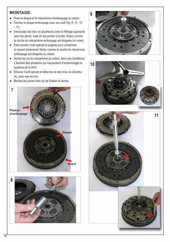
MONTAGE:● Posé le disque et le mécanisme d’embrayage au volant.● Centrez le disque embrayage avec son outil (fig. 8 - 9 - 10 - 11).● Introduisez les trois vis (écarteurs) avec le filetage approprié sans les serrer, mais en les portant à butée. Notez comme la cloche du mécanisme embrayage est éloignée du volant.● Faire pivoter l’outil spécial la poignée pour comprimer le ressort totalement; Notez comme la cloche du mécansme embrayage est éloignée du volant.● Serrez les vis du mécanisme au volant, dans ces conditions, il faudrait des pressions qui risqueraient d’endommager le système de la SAC.● Enlevez l’outil spécial et détachez-le des trois vis (écarteu rs), avec ses écrous.● Montez les autres trois vis de fixation et serrez.
7
8
9
10
11
Plateaud’embrayage
Volant
Disque

17
● Bouchon fileté pour la protection du filet intérieur● 2 éléments de centrage / tensionneur pour le palier de guidage ou le trou de l’arbre moteur● Centreur avec guide et élément tensionneur● 6 différentes douilles coniques pour écarter les 2 éléments de centrage / tensionneur● 3 goujons de centrage et dévissage avec diamètres différents pour le palier de guidage
CENTRAGE DISQUE D’EMBRAYAGE:Pour un assemblage correct de la transmission et un fonctionnement correct de l’embrayage, le centrage du disque est essentiel.
Pour un bon centrage pendant les phases d’as-semblage, introduire soigneusement le centreur du disque d’embrayage. Ainsi le risque d’endomma-gement du disque d’embrayage est réduit.
POSSIBLES UTILISATIONS DU GOU-JON DE CENTRAGE UNIVERSEL:Le centreur universel a été conçu pour une appli-cation universelle sur toutes les voitures.Normalement dans le trou de l’arbre moteur il y a un palier de guidage, dont le diamètre intérieur est plus petit de celui du moyeu.
Ce centreur peut être utilisé aussi en absence du palier de guidage. Dans ces cas le diamètre intérieur du trou de l’arbre moteur peut être plus grand de celui du moyeu.
Le choix du goujon de centrage / centreur à utiliser dépend du diamètre intérieur du palier de guidage / trou de l’arbre moteur et de la distance entre le palier de guidage / trou de l’arbre moteur et le profil du moyeu du disque d’embrayage.
Vous pouvez combiner les différents compo-sants pour trouver le goujon de centrage le plus indiqué.Si vous n’utilisez aucun goujon de centrage, vissez le bouchon fileté de protection du filet intérieur pour protéger le filet de la saleté et d’éventuels dommages.
Définir les éléments de centrage et tensionneur à utiliser conformément à la hauteur de la guide de l’arbre moteur et du moyeu du disque d’embra-yage.
18
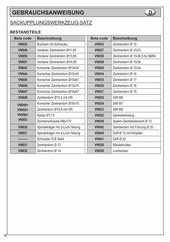
GEBRAUCHSANWEISUNG DSACKUPPLUNGSWERKZEUG-SATZ
BESTANDTEILEBeta code Beschreibung Beta code Beschreibung
VN952 Buchsen mit Schraube VN933 Zentrierdorn Ø 15VN949 Vorderer Zentrierdorn Ø11,85 VN927 Zentrierdorn Ø 15/23VN950 Vorderer Zentrierdorn Ø13,85 VN938 Zentrierdorn Ø 15/26.5 für BMWVN951 Vorderer Zentrierdorn Ø14,85 VN928 Zentrierdorn Ø 15/28VN943 Konischer Zentrierdorn Ø15x30 VN929 Zentrierdorn Ø 15/34VN944 Konischer Zentrierdorn Ø15x40 VN934 Zentrierdorn Ø 16VN945 Konischer Zentrierdorn Ø15x67 VN935 Zentrierdorn Ø 17VN946 Konischer Zentrierdorn Ø15x75 VN936 Zentrierdorn Ø 18VN947 Konischer Zentrierdorn Ø18x67 VN937 Zentrierdorn Ø 19VN948 Zentrierdorn Ø15,5 mit OR VN925 Stift M6
VN948+VN955+VN956+VN953
Konischer Zentrierdorn Ø18x75 VN924 Stift M7Zentrierdorn Ø19,8 mit OR VN923 Stift M8Spitze Ø17,8 VN922 SpreizwerkzeugZentrierschraube M8x170 VN930 Spann-/Zentrierelement Ø 12
VN920 Spindelträger mit 3-Loch-Teilung VN942 Zentrierdorn mit Führung Ø 20VN921 Spindelträger mit 4-Loch-Teilung VN940 Griff Ø 12 mit Knöpfen---------- Schraube TCE 8x45 VN941 Griff Ø 20VN931 Zentrierdorn Ø 12 VN926 RändelmutterVN932 Zentrierdorn Ø 14 VN939 Lochbolzen
19
GEBRAUCHSANWEISUNG D
Mit dem SAC-Kupplungswerkzeug-Satz können SACKupplungen schnell und fach-gerecht ein- und ausgebaut werden, Passend für nahezu alle SAC-Kupplungen mit 3- und 4-Loch Teilung:
Marke ModelleAlfa romeo 147 - 159 - 166 - Brera - SpiderAudi A3 - A4 - A6 - A8 - TTBmw 320 - 330 - 520 - 530Citroën C-CrosserFiat Ulisse - Croma - Ducato - Bravo - StiloFord Mondeo - Galaxy - Transit - S-Max - Focus C-MaxHyundai H-1 - I30 - Santa Fè - Sonata - TusconLancia Delta - Thesis - PhedraMercedes C - E - CLS - S - CLK - SLK - SLMitsubishi Grandis - OutlanderOpel VivaroPeugeot 4007Renault Espace IV - Laguna - Laguna II - Laguna III - Trafic II - Vel SatisSeat Altea - Leon - Toledo IISkoda Octavia - SuperbVauxhall Vivaro
Volkswagen Eos - Golf IV - Golf V - Golf V Plus - Jetta II - Multivan T5 - Passat - Passat CC - Scirocco - Touran - Transporter V
Volvo Volvo S40 II - V50
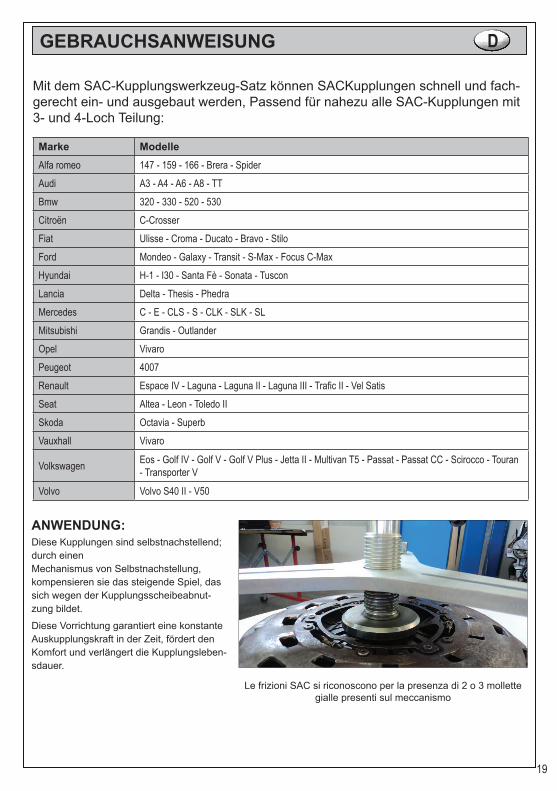
ANWENDUNG:Diese Kupplungen sind selbstnachstellend; durch einenMechanismus von Selbstnachstellung, kompensieren sie das steigende Spiel, das sich wegen der Kupplungsscheibeabnut-zung bildet.
Diese Vorrichtung garantiert eine konstanteAuskupplungskraft in der Zeit, fördert den Komfort und verlängert die Kupplungsleben-sdauer.
Le frizioni SAC si riconoscono per la presenza di 2 o 3 mollette gialle presenti sul meccanismo

20
Bitte während des Einbaus dieser Kupplun-gen aufmerksam machen; ein unkorrekterEinbau könnte Verformungen der Glocke von dem Kupplungsmechanismus oder einenNachstellungsverlust verursachen.
Das ist mit den Schwierigkeit verbunden, die unterGarantie-Stücke zu erkennen, deren Funktionsstörungvon Einbaufehlern verursacht ist
Um diese Zwischenfälle zu vermeiden, den richtigenEinbau und Ausbau dieser SAC-Kupplungen durch einspezielles Werkzeug durchführen.
AUSBAU:Es ist absolut erforderlich die Verwendung dieses speziellen Werkzeugs für den Einbau und Ausbau der selbstnachstellenden Kupplungen (SAC).Wenn wir eine SAC-Kupplung ohne das spezielleWerkzeug auszubauen versuchen, verliert die Kupplung ihre Nach-stellung mit folgenden Funktionsstörungen während des Einbaus.
Bitte halten Sie sich an diese Anleitungen:● Den Griff hinein den Knebel montieren (Bezug 1).● 3 Deckel-Befestigungsschrauben versetzt um 120° heraus schrauben (4 er Teilung versetz um 90° aufschrauben und entnehmen, (Bezug 2).● Passende gelieferten Gewindebolzen M6, M7 oder M8 auswählen und einbauen (Bezug 3 und 4).● SAC-Spannvorrichtung über die Gewindebolzen führen (3 oder 4 Arm-Platte) und mit dem Aufnahmegewinde M8 am Spanndorn verschrauben.● Druckspindel am Knebel einschrauben bis der Druckpilz auf die Tellerfeder drückt (Bezug 5).● Nun die restlichen Befestigungsschrauben heraus schrau ben. Durch Zurückdrehen der Druckspindel wird nun die Tellerfeder entlastet (Bezug 6).● 6-kant-Muttern abschrauben und Traverse entnehmen.● Abschließend die Gewindebolzen entfernen und die Kupplung entnehmen (Bezug 7).
1
2
3
4
5
6

21
EINBAU:● Neue Kupplungsdruckplatte am Schwungrad platzieren (Zentrierstifte beachten).● Den gelieferten Werkzeug verwenden (Bezug 8 - 9 - 10 - 11).● Die 3 passende Stifte hineinlegen aber nicht zu viel schraube, kann für SAC- System gefährlich sein.● Die Druckplatte einsetzen und es mit den M8 Befestigung schrauben fixieren.● Die Glocke wird nicht an das Schwungrad angeschlossen● Zum Drücken der Feder komplett, der SACSpannvorrichtung mit Hand drehen; Jetzt wird die Glocke wird an das Schwungrad angeschlossen.● Befestigungsschrauben einsetzen und aufschrauben;● Tellerfeder wird entspannt. Die ganze Teile entfernen.● Befestigungsschrauben handfest in die frei gewordenen Gewindeaufnahmen am Schwungrad einschrauben.
7
8
9
10
11
Drucksplindel
Kupplung
Platte

22
● Gewindeverschlussdeckel zum Schutz des Innengewindes● Zwei Spann-/Zentrierelemente für Führungslager oder Kurbelwellenbohrung● Zentrierdorn mit Führung und Spannelement● Sechs unterschiedliche konische Buchsen zur Spreizung der beiden Spann-/Zentrierelemente, für die Aufnahme der Kupplungsscheibe● Drei aufschraubbare Zentrierdorne mit unterschie dlichen Durchmessern für Führungslager
ZENTRIERUNG DER KUPPLUNG-SCHEIBE:Die Zentrierung der Kupplungsscheibe ist von zentralerBedeutung für die korrekte Montage des Getriebes undfür die Funktion der Kupplung. Eine ordnungsgemäßeZentrierung sorgt dafür, dass die Getriebeeingangswellebei der Montage leichtgängig durch die Kupplungsscheibegeführt wird.Die Gefahr einer Beschädigung der Kupplungsscheibewird somit minimiert.Um die Zentrierung der Kupplungsscheibe an möglichstallen Fahrzeugtypen durchführen zu können, wurdeein Baukastensystem für einen Universal-Zentrierdornentwickelt. Dieses erlaubt es, den Zentrierdorn durchKombination der verschiedenen Einzelteile für denBedarfsfall passend zusammenzustellen.
KOMBINATIONSMÖGLICHKEITEN DES UNIVERSAL-ZENTRIERDORNSDer Universal-Zentrierdorn ist grundsätzlich für dieAnwendung an allen Fahrzeugtypen geeignet.In der Regel befindet sich ein Führungslager in derKurbelwellenbohrung. Dessen Innendurchmesser ist
kleiner als der der Nabe. Die Besonderheit des Universal-Zentrierdorns ist, dass er auch bei Anwendungen ohne Führungslager eingesetzt werden kann. In diesen Fällen kann der Innen-durchmesser der Kurbelwellenbohrung größer sein als der der Nabe.Welche Zusammenstellung des Zentrierdornszum Einsatz kommt, ist zum einen abhängig vomInnendurchmesser des Führungslagers / derKurbelwellenbohrung.Zum anderen hängt sie von der Distanz zwischen dem Führungslager / der Kurbelwellenbohrung und dem Nabenprofil der Kupplungsscheibe ab.
Die unterschiedlichen Komponenten können beliebig miteinander kombiniert werden, um den passendenZentrierdorn zusammenzustellen.
Wird keiner der drei aufschraubbaren Zentrier-dorne verwendet, ist der Gewindeverschlussde-ckel aufzuschrauben. Damit ist das Gewinde vor Schmutz und Beschädigung geschützt.
Die Spann-/Zentrierelemente müssen sich auf Höhe der Kurbelwellenführung und der Kup-plungsscheibennabe befinden.

23
INSTRUCCIONES E
KIT ESPECÍFICO PARA CENTRAJE EMBRAGUES SAC, CENTRA-DOR INCLUIDO
COMPONENTESCódigo Beta Descripción Código Beta Descripción
VN952 Casquillo con tornillo montado VN933 Centraje Ø 15VN949 Centraje delantero Ø11,85 VN927 Centraje Ø 15/23
VN950 Centraje delantero Ø13,85 VN938 Centraje Ø 15/26.5 embragues BMW
VN951 Centraje delantero Ø14,85 VN928 Centraje Ø 15/28VN943 Centraggio conico Ø15x30 VN929 Centraje Ø 15/34VN944 Centraje cónico Ø15x40 VN934 Centraje Ø 16VN945 Centraje cónico Ø15x67 VN935 Centraje Ø 17VN946 Centraje cónico Ø15x75 VN936 Centraje Ø 18VN947 Centraje cónico Ø18x67 VN937 Centraje Ø 19VN948 Centraje Ø15,5 con OR montates VN925 Perno M6
VN948+VN955+VN956+VN953
Centraje cónico Ø18x75 VN924 Perno M7Centraje Ø19,8 con OR montates VN923 Perno M8Virola Ø17,8 VN922 DesguazadoraTornillo central M8x170 VN930 Expansor Ø 12 de resina
VN920 Placa 3 brazos VN942 Mango centrador Ø 20
VN921 Placa 4 brazos VN940 Mango Ø 12 completo con pomos esféricos
---------- Tornillo TCE 8x45 VN941 Mango fijo Ø 20VN931 Centraje Ø 12 VN926 PomosVN932 Centraje Ø 14 VN939 Perno agujereado
24
INSTRUCCIONES E
En la actualidad cada vez más los vehículos tienen montados los embragues llama-dos SAC (Self Adjusting Clutch), he aquí algunos modelos:
Marca ModeloAlfa romeo 147 - 159 - 166 - Brera - SpiderAudi A3 - A4 - A6 - A8 - TTBmw 320 - 330 - 520 - 530Citroën C-CrosserFiat Ulisse - Croma - Ducato - Bravo - StiloFord Mondeo - Galaxy - Transit - S-Max - Focus C-MaxHyundai H-1 - I30 - Santa Fè - Sonata - TusconLancia Delta - Thesis - PhedraMercedes C - E - CLS - S - CLK - SLK - SLMitsubishi Grandis - OutlanderOpel VivaroPeugeot 4007Renault Espace IV - Laguna - Laguna II - Laguna III - Trafic II - Vel SatisSeat Altea - Leon - Toledo IISkoda Octavia - SuperbVauxhall Vivaro
Volkswagen Eos - Golf IV - Golf V - Golf V Plus - Jetta II - Multivan T5 - Passat - Passat CC - Scirocco - Touran - Transporter V
Volvo Volvo S40 II - V50
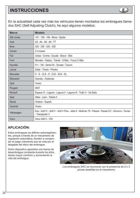
APLICACIÓN:Estos embragues se definen autorregistran-tes, porque a través de un mecanismo de regulación automática, tienden a compen-sar el juego cresciente que se crea por el desgaste del disco del embrague.
Dicho dispositivo garantiza una fuerza de desembrague constante durante los años, dando mayor comfortn y aumentando la vida del embrague.
Los embragues SAC se reconocen por la presencia de 2 o 3 pinzas amarillas en el mecanismo

25
Es necesario poner mucha atención durante el montaje de los embragues, ya que un montaje no correcto podría causar deformaciones de la campana del mecani-smo embrague o pérdida de regulación del mismo.
Esto conlleva a la dificultad de reconocer en garantíapiezas cuyo mal funcionamiento se atribuye a errores de montaje..Para evitar estos inconvenientes, el montaje ydesmontaje de los embragues SAC se tiene que realizar utilizando la herramienta especial.
DESMONTAJE:Es obligatorio utilizar esta herramienta especial para desmontar los embragues autorregulables (SAC).Si trataramos de desmontar un embrague SAC sin la herramienta, el embrague perdería su regulación y causaría problemas de funcionamiento cuando se vuelve a montar.
Seguire le seguenti istruzioni:● Montar el mango según la (figura 1).● Desatornillar del mecanismos los 3 tornillos de 120° (o 4 tornillos de 90°, (fig. 2).● Montar los tornillos correspondientes M6, M7 o M8 (distanciadores) en dotación (fig. 3 y 4).● Instalar la herramienta especial de fijación (3 o 4 brazos) y fijar las truercas M8.● Girar el mango de la herramienta especial para fijar comple tamente la tapa cubre muelle (fig. 5).● Desatornillar los otros tornillos de fijación del volante (fig. 6).● Quitar las tuercas M8 de la herramienta especial, y luego la herramienta especial y los 3 distanciadores.● Ahora se puede elevar el plato de presión, la campana del mecanismo embrague está a tope con el volante, esto hace que se pueda quitar el embrague con facilidad (fig. 7).
1
2
3
4
5
6

26
MONTAJE:● Apoyar el disco y el mecanismo embrague en el volante.● Centrar el disco embrague usando la relativa herramienta entregada en dotación (fig. 8 - 9 - 10 - 11)● Introducir los tres tornillos (distanciadores) sin apretarlos porque podría estropear el mecanismo SAC.● Instalar la herramienta especial de bloqueo y bloquearla con los tres pernos entregados en dotación.● Nótese como la campana del mecanismo embrague ya no está en contacto con el volante.● Girar el mango de la herramienta especial para fijar comple tamene el muelle. Ahora la campana está a tope con el volante.● Colocar y atornillar los tornillos de fijación en el volante.● Descargar la presión de la herramienta y quitar todas las piezas.● Montar los tres tornillos y acabar la operación.
7
8
9
10
11
Plato de presión
Volante
Plato
27
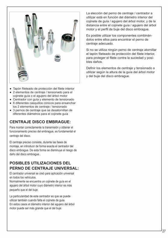
● Tapón fileteado de protección del filete interior● 2 elementos de centraje / tensionado para el cojinete guía o el agujero del árbol motor● Centrador con guía y elemento de tensionado● 6 diferentes casquillos cónicos para ensanchar los 2 elementos de centraje / tensionado● 3 pernos de centraje que se desatornillan de diferentes diámetros para el cojinete guía
CENTRAJE DISCO EMBRAGUE:Para montar correctamente la transmisión y obtener elfuncionamiento preciso del embrague, es fundamental elcentraje del disco.
El centraje preciso consiste, durante las fases demontaje, en introducir de forma exacta el centrador deldisco embrague. De esta forma se disminuye el riesgo dedaño del disco embrague..
POSIBLES UTILIZACIONES DEL PERNO DE CENTRAJE UNIVERSAL:El centrador universal se creó para aplicación universalen todos los vehículos.Normalmente se encuentra un cojinete de guía en elagujero del árbol motor cuyo diámetro interior es máspequeño que el del buje.
La particularidad de este centrador es que se puedeutilizar también cuando falta el cojinete de guía.En estos casos el diámetro interior del agujero del árbolmotor puede ser más grande que el del buje.
La elección del perno de centraje / centrador a utilizar está en función del diámetro interior del cojinete de guía / agujero del árbol motor, y de la distancia entre el cojinete guía / agujero del árbol motor y el perfil de buje del disco embrague.
Es posible utilizar los componentes combinán-dolos entre ellos para encontrar el perno de centraje adecuado.
Si no se utiliza ningún perno de centraje atornillar el tapón fileteado de protección del filete interior, para proteger el filete contra la suciedad y posi-bles daños.
Definir los elementos de centraje y tensionado a utilizar según la altura de la guía del árbol motor y del buje del disco embrague.

28
GEBRUIKSAANWIJZING NLSPECIFIEKE SET VOOR HET CENTREREN VAN SAC- KOPPELIN-GEN, INCLUSIEF CENTREERWERKTUIG
ONDERDELENBeta code Beschrijving Beta code Beschrijving
VN952 Bus met voorgemonteerde schroef VN933 Centreerwerktuig Ø 15VN949 Centreerwerktuig voorzijde Ø11,85 VN927 Centreerwerktuig Ø 15/23
VN950 Centreerwerktuig voorzijde Ø13,85 VN938 Centreerwerktuig Ø 15/26.5 koppelingen BMW
VN951 Centreerwerktuig voorzijde Ø14,85 VN928 Centreerwerktuig Ø 15/28VN943 Centreerconus Ø15x30 VN929 Centreerwerktuig Ø 15/34VN944 Centreerconus Ø15x40 VN934 Centreerwerktuig Ø 16VN945 Centreerconus Ø15x67 VN935 Centreerwerktuig Ø 17VN946 Centreerconus Ø15x75 VN936 Centreerwerktuig Ø 18VN947 Centreerconus Ø18x67 VN937 Centreerwerktuig Ø 19
VN948 Centreerwerktuig Ø15,5 met voorgemonteerde O-ringen VN925 M6 pin
VN948+VN955+VN956+VN953
Centreerconus Ø18x75 VN924 M7 pinCentreerwerktuig Ø19,8 met voorgemonteerde O-ringen VN923 M8 pin
Plunjer Ø17,8 VN922 SpreiderSchroef in het midden M8x170 VN930 Hars expander Ø 12
VN920 Plaat 3 armen VN942 Centreerhandgreep Ø 20
VN921 Plaat 4 armen VN940 Handgreep Ø 12 compleet met ronde knoppen
---------- Inbusschroef 8x45 VN941 Vaste handgreep Ø 20VN931 Centreerwerktuig Ø 12 VN926 KnopVN932 Centreerwerktuig Ø 14 VN939 Pen met gat
29
GEBRUIKSAANWIJZING NL
Tegenwoordig hebben steeds meer auto’s zogenaamde SAC (Self Adju¬sting Clutch)-koppelingen. Vervolgens worden enkele modellen genoemd:
Merk ModelAlfa romeo 147 - 159 - 166 - Brera - SpiderAudi A3 - A4 - A6 - A8 - TTBmw 320 - 330 - 520 - 530Citroën C-CrosserFiat Ulisse - Croma - Ducato - Bravo - StiloFord Mondeo - Galaxy - Transit - S-Max - Focus C-MaxHyundai H-1 - I30 - Santa Fè - Sonata - TusconLancia Delta - Thesis - PhedraMercedes C - E - CLS - S - CLK - SLK - SLMitsubishi Grandis - OutlanderOpel VivaroPeugeot 4007Renault Espace IV - Laguna - Laguna II - Laguna III - Trafic II - Vel SatisSeat Altea - Leon - Toledo IISkoda Octavia - SuperbVauxhall Vivaro
Volkswagen Eos - Golf IV - Golf V - Golf V Plus - Jetta II - Multivan T5 - Passat - Passat CC - Scirocco - Touran - Transporter V
Volvo Volvo S40 II - V50
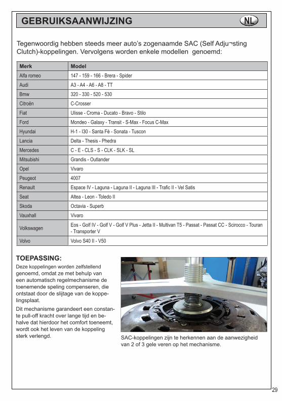
TOEPASSING:Deze koppelingen worden zelfstellend genoemd, omdat ze met behulp van een automatisch regelmechanisme de toenemende speling compenseren, die ontstaat door de slijtage van de koppe-lingsplaat. Dit mechanisme garandeert een constan-te pull-off kracht over lange tijd en be-halve dat hierdoor het comfort toeneemt, wordt ook het leven van de koppeling sterk verlengd. SAC-koppelingen zijn te herkennen aan de aanwezigheid
van 2 of 3 gele veren op het mechanisme.
30
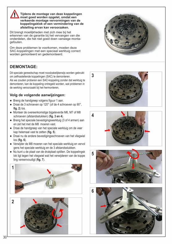
Tijdens de montage van deze koppelingen moet goed worden opgelet, omdat een verkeerde montage vervormingen van de koppelingsklok of een vermindering van de afstelling ervan kan veroorzaken.
Dit brengt moeilijkheden met zich mee bij het erkennen van de garantie bij het vervangen van die onderdelen, die het niet goed doen vanwege monta-gefouten.
Om deze problemen te voorkomen, moeten deze SAC-koppelingen met een speciaal werktuig correct worden gemonteerd en gedemonteerd.
DEMONTAGE:Dit speciale gereedschap moet noodzakelijkerwijs worden gebruikt om zelfnastellende koppelingen (SAC) te demonteren.Als we zouden proberen een SAC-koppeling zonder dat werktuig te demonteren, kan de koppeling ontregeld worden, wat problemen in de werking veroorzaakt bij het hermonteren,
Volg de volgende aanwijzingen:● Breng de handgreep volgens figuur 1 aan.● Draai de 3 schroeven op 120° (of de 4 schroeven op 90°, fig. 2) los.● Monteer de overeenkomstige bijgeleverde M6, M7 of M8 schroeven (afstandsstukken) (fig. 3 en 4).● Breng het speciale bevestigingswerktuig (3 of 4 armen) aan en zet het met de M8 moeren vast.● Draai de handgreep van het speciale werktuig om de veer kap helemaal vast te zetten (fig. 5).● Draai nu de andere bevestigingsschroeven van het vliegwiel los (fig. 6).● Verwijder de M8 moeren van het speciale werktuig en vervol gens het speciale werktuig en de 3 afstandsstukken.● Nu kunt u de plaat van de drukplaat optillen. De koppelingsk lok ligt tegen het vliegwiel wat het verwijderen van de koppe ling vereenvoudigt (fig. 7).
1
2
3
4
5
6

31
MONTAGE:● Leg de plaat en het koppelingsmechanisme op het vliegwiel.● Centreer de koppelingsplaat met behulp van het speciaal hiervoor bestemde bijgeleverde werktuig (fig. 8 - 9 - 10 - 11).● Breng de drie schroeven (afstandsstukken) aan zonder ze aan te draaien, omdat het SAC-mechanisme anders beschadigd wordt.● Breng het speciale blokkeerwerktuig aan en zet het met de drie bijgeleverde bouten vast. U merkt nu dat de koppelingsklok geen contact meer maakt met het vliegwiel.● Draai de handgreep van het speciale werktuig om de veer helemaal vast te zetten. De koppelingsklok ligt nu helemaal tegen het vliegwiel aan.● Breng de bevestigingsschroeven op het vliegwiel aan en draai ze aan.● Neem de druk van het gereedschap en verwijder alle delen.● Breng de drie schroeven aan en beëindig de operatie.
7
8
9
10
11
Drukplaat
Vliegwiel
Plaat

32
● Dop met schroefdraad ter bescherming van de interne schroefdraad● 2 centreer- / spanelementen voor het geleidingsla ger of het gat van de krukas● Centreerwerktuig met geleiding en spanelement● 6 verschillende conische bussen om de 2 centreer / spanelementen te vergroten● 3 centreerpennen voor het losschroeven, met verschillende diameters voor het geleidingslager
DE KOPPELINGSPLAAT CENTRE-RENDe centrering van de plaat is van fundamenteel belang voor een correcte montage van de transmissie en een goede werking van de koppeling.Een correcte centrering bestaat tijdens de montagefasen uit het zorgvuldig invoeren van het centreerwerktuig van de koppelingsplaat. Op die manier wordt het gevaar dat de kop-pelingsplaat beschadigd wordt tot een minimum beperkt.
GEBRUIKSMOGELIJKHEDEN VAN DE UNIVERSELE CENTREERPEN:Het universele centreerwerktuig is ontwikkeld voor een universele toepassing op alle auto’s.Normaal gesproken bevindt zich een geleidingslager in het gat van de krukas, waarvan de interne diameter kleiner is dan die van de naaf.Het bijzondere van dit centreerwerktuig is dat het ook kan worden gebruikt als het geleidingslager ontbreekt.In dat geval kan de interne diameter van het gat van de krukas groter zijn dan die van de naaf.
De te gebruiken centreerpen / het te gebruiken centreerwerktuig wordt gekozen afhankelijk van de interne diameter van het geleidingslager / gat van de krukas, en van de afstand tussen het geleidingslager / gat van de krukas en het profiel van de naaf van de koppelingsplaat.De verschillende onderdelen kunnen worden ge-bruikt om ze onderling met elkaar te combineren om de geschikte centreerpen te vinden.Als er geen centreerpen wordt gebruikt, draait u de dop met schroefdraad ter bescherming van de interne schroefdraad aan, zodat de schro-efdraad tegen vuil en eventuele schade wordt beschermd.Bepaal de centreer- en spanelementen die ge-bruikt moet worden op grond van de hoogte van de geleiding van de krukas en de naaf van de koppelingsplaat.

33
INSTRUKCJA OBSŁUGI PLSPECJALNY ZESTAW DO CENTROWANIA SPRZĘGIEŁ SAC, ZA-WIERA ELEMENT CENTRUJĄCY
KOMPONENTYKod Beta Opis Kod Beta Opis
VN952 Tuleja z zamocowaną śrubą VN933 Wałek centrujący Ø 15VN949 Trzpień centrujący przedni Ø11,85 VN927 Wałek centrujący Ø 15/23
VN950 Trzpień centrujący przedni Ø13,85 VN938 Wałek centrujący Ø 15/26.5
sprzęgła BMW
VN951 Trzpień centrujący przedni Ø14,85 VN928 Wałek centrujący Ø 15/28
VN943 Trzpień centrujący stożkowy Ø15x30 VN929 Wałek centrujący Ø 15/34
VN944 Trzpień centrujący stożkowy Ø15x40 VN934 Wałek centrujący Ø 16
VN945 Trzpień centrujący stożkowy Ø15x67 VN935 Wałek centrujący Ø 17
VN946 Trzpień centrujący stożkowy Ø15x75 VN936 Wałek centrujący Ø 18
VN947 Trzpień centrujący stożkowy Ø18x67 VN937 Wałek centrujący Ø 19
VN948 Tuleja centrująca Ø15,5 z uszczel-kami O-Ring VN925 Szpilka M6
VN948+VN955+VN956+VN953
Trzpień centrujący stożkowy Ø18x75 VN924 Szpilka M7
Tuleja centrująca Ø19,8 z uszczel-kami O-Ring VN923 Szpilka M8
Prowadnica Ø17,8 VN922 RozwieraczWkręt centralny M8x170 VN930 Ekspander Ø 12 z tworzywa
VN920 Wspornik 3 - ramienny VN942 Uchwyt centrujący Ø 20
VN921 Wspornik 4 - ramienny VN940 Uchwyt Ø 12 wraz ze sferycznymi pokrętlami
---------- Śruba TCE 8x45 VN941 Uchwyt stały Ø 20VN931 Wałek centrujący Ø 12 VN926 PokrętłoVN932 Wałek centrujący Ø 14 VN939 Perforowany trzpień
34
INSTRUKCJA OBSŁUGI PL
Obecnie coraz więcej samochodów wyposażonych jest w sprzęgla o nazwie SAC (Self Adjusting Clutch), poniżej wymienione są niektóre modele:
Marka ModelAlfa romeo 147 - 159 - 166 - Brera - SpiderAudi A3 - A4 - A6 - A8 - TTBmw 320 - 330 - 520 - 530Citroën C-CrosserFiat Ulisse - Croma - Ducato - Bravo - StiloFord Mondeo - Galaxy - Transit - S-Max - Focus C-MaxHyundai H-1 - I30 - Santa Fè - Sonata - TusconLancia Delta - Thesis - PhedraMercedes C - E - CLS - S - CLK - SLK - SLMitsubishi Grandis - OutlanderOpel VivaroPeugeot 4007Renault Espace IV - Laguna - Laguna II - Laguna III - Trafic II - Vel SatisSeat Altea - Leon - Toledo IISkoda Octavia - SuperbVauxhall Vivaro
Volkswagen Eos - Golf IV - Golf V - Golf V Plus - Jetta II - Multivan T5 - Passat - Passat CC - Scirocco - Touran - Transporter V
Volvo Volvo S40 II - V50
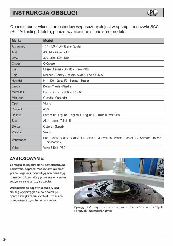
ZASTOSOWANIE:Sprzęgła te są określane samonastawne, ponieważ, poprzez mechanizm automat-ycznej regulacji, powodują kompensację rosnącego luzu, który powstaje w wyniku zużywania się tarczy sprzęgła.
Urządzenie to zapewnia stałą w cza-sie siłę wysprzęglania co powoduje, oprócz zwiększenia komfortu, znaczne przedłużenie żywotności sprzęgła.
Sprzęgła SAC są rozpoznawalne przez obecność 2 lub 3 żółtych sprężynek na mechaniźmie
35
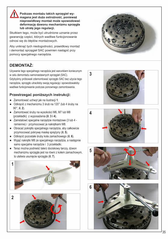
Podczas montażu takich sprzęgieł wy-magana jest duża ostrożność, ponieważ nieprawidłowy montaż może spowodować deformację dzwonu mechanizmu sprzęgła lub utratę jego regulacji.
Skutkiem tego, może być utrudnione uznanie przez gwarancję części, których wadliwe funkcjonowanie odnosi się do błędów montażowych.
Aby uniknąć tych niedogodności, prawidłowy montaż i demontaż sprzęgieł SAC powinien nastąpić przy pomocy specjalnego narzędzia.
DEMONTAŻ:Używanie tego specjalnego narzędzia jest warunkiem koniecznym w celu demontażu samonastawnych sprzęgieł (SAC).Gdybyśmy próbowali zdemontować sprzęgło SAC bez użycia tego narzędzia, sprzęgło utraciłoby swoją regulację i spowodowałoby wadliwe funkcjonwanie podczas ponownego zamontowania.
Przestrzegać poniższych instrukcji:● Zamontować uchwyt jak na ilustracji 1.● Odkręcić z mechanizmu 3 śrub na 120° (lub 4 śruby na 90°, il. 2).● Zamontować śruby na wysokości M6, M7 lub M8 (przekładki) z wyposażenia (il. 3 i 4).● Zainstalowć specjalne narzędzie montażowe (3 lub 4 - ramienne) i przymocować je nakrętkami M8.● Obracać pokrętło specjalnego narzędzia, aby całkowicie przymocować pokrywę maskę sprężyny (il. 5).● Odkręcić pozostałe śruby koła zamachowego (il. 6).● Wyjąć nakrętki M8 ze specjalnego narzędzia, a następnie samo specjalne narzędzie i 3 przekładki.● Teraz można podnieść talerz dociskowy tarczy, dzwon mechanizmu sprzęgła jest na równi z kołem zamachowym, to ułatwia usunięcie sprzęgła (il. 7).
1
2
3
4
5
6

36
MONTAŻ:● Oprzeć tarczę i mechanizm sprzęgła o koło zamachowe.● Wycentrować tarczę sprzęgła za pomocą odpowiedniego narzędzia dostarczonego w wyposażeniu (il. 8 – 9 – 10 - 11).● Wstawić trzy śruby (przekładki) bez dokręcania, ponieważ mogłoby to spowodować uszkodzenie mechanizmu SAC.● Zainstalować narzędzie specjalne do zablokowania i zabezpieczyć je za pomocą trzech dostarczonych śrub. Należy zauważyć, że dzwon mechanizmu sprzęgła nie dotyka już koła zamachowego.● Obracać pokrętło specjalnego narzędzia, aby całkowicie przymocować sprężynę. Teraz dzwon jest na równi z kołem zamachowym.● Umieścić i wkręcić śruby montażowe do koła zamachowego.● Uwolnić narzędzie spod nacisku i usunąć wszystkie ele- menty.● Wkręcić trzy śruby i zakończyć operację.
7
8
9
10
11
Docisk
Koło zamachowe
Talerz

37
● Gwintowana osłona gwintu wewnętrznego● 2 nasadki napinająco-centrujące do łożyska pilotującego lub otworu wału korbowego● Wałek centrujący z prowadnicą i elementem napinającym● 6 różnych trzpieni stożkowych do rozprężenia 2 końcówek centrujących lub napinających● 3 trzpienie centrujące do wykręcania o różnej średnicy do łożyska pilotującego
CENTROWANIE TARCZY SPRZĘGŁA:Poprawne wycentrowanie tarczy jest niezbędne dlaprawidłowego montażu przekładni i działania zespołu sprzęgła.Właściwe centrowanie polega na dokładnym wprowadzeniu, podczas faz montażu, trzpienia centrującegotarczy sprzęgła. W ten sposób minimalizuje się ryzykouszkodzenia tarczy sprzęgła.
MOŻLIWE ZASTOSOWANIA UNIWERSALNEGO TRZPIENIA CENTRUJĄCEGO:Uniwersalny trzpień centrujący przeznaczony jest do uniwersalnego stosowania we wszystkich samochodach.Na ogół łożysko pilotujące znajduje się w otworzewału korbowego, którego wewnętrzna średnica jest mniejs-za od średnicy piasty.Szczególną cechą tego trzpienia centrującego jest to, że może on być również stosowany, gdy brakuje łożyska pilotującego.W tych przypadkach średnica otworu wału korbowego może być większa od piasty.
Wybór trzpienia centrującego do użycia zależy od średnicy wewnętrznej łożyska pilotującego lub otworu wału korbowe-go, oraz od odległości pomiędzy łożyskiem pilotującym lub otworem wału korbowego, a profilem piasty tarczy sprzęgła.
Pojedyncze elementy można dowolnie dobierać, łącząc je pomiędzy sobą, aby znaleźć odpowiedni trzpień centrujący.
Jeśli nie jest używany żaden trzpień centrujący, wkręcić gwintowaną osłonę gwintu wewnętrznego, w celu za-bezpieczenia gwintu przed brudem i zniszczeniem.
Wybierać elementy napinająco-centrujące, z których należy korzystać na podstawie wysokości prowadnicy wału korbo-wego silnika oraz piasty tarczy sprzęgła.

38
INSTRUÇÕES DE USO P
KIT ESPECÍFICO PARA CENTRAR EMBRAIAGENS SAC, CENTRA-DOR INCLUÍDO
COMPONENTES
Código Beta Descrição Código Beta DescriçãoVN952 Bucha com parafuso montado VN933 Centragem Ø 15VN949 Centragem dianteira Ø11,85 VN927 Centragem Ø 15/23
VN950 Centragem dianteira Ø13,85 VN938 Centragem Ø 15/26.5 embraia-gens BMW
VN951 Centragem dianteira Ø14,85 VN928 Centragem Ø 15/28VN943 Centragem cónica Ø15x30 VN929 Centragem Ø 15/34VN944 Centragem cónica Ø15x40 VN934 Centragem Ø 16VN945 Centragem cónica Ø15x67 VN935 Centragem Ø 17VN946 Centragem cónica Ø15x75 VN936 Centragem Ø 18VN947 Centragem cónica Ø18x67 VN937 Centragem Ø 19
VN948 Centragem Ø15,5 com OR montados VN925 Pino M6
VN948+VN955+VN956+VN953
Centragem cónica Ø18x75 VN924 Pino M7Centragem Ø19,8 com OR montados VN923 Pino M8
Ponteira Ø17,8 VN922 SeparadorParafuso central M8x170 VN930 Dilatador Ø 12 em resina
VN920 Placa 3 braços VN942 Pega centradora Ø 20
VN921 Placa 4 braços VN940 Pega Ø 12 completa com punhos esféricos
---------- Parafuso cabeça cilíndrica hexa-gonal 8x45 VN941 Pega fixa Ø 20
VN931 Centragem Ø 12 VN926 BotãoVN932 Centragem Ø 14 VN939 Pino furado

39
INSTRUÇÕES DE USO P
Hoje em dia cada vez mais automóveis montam as embraiagens denominadas SAC (Self Adju¬sting Clutch), a seguir são indicados alguns modelos:
Marca ModeloAlfa romeo 147 - 159 - 166 - Brera - SpiderAudi A3 - A4 - A6 - A8 - TTBmw 320 - 330 - 520 - 530Citroën C-CrosserFiat Ulisse - Croma - Ducato - Bravo - StiloFord Mondeo - Galaxy - Transit - S-Max - Focus C-MaxHyundai H-1 - I30 - Santa Fè - Sonata - TusconLancia Delta - Thesis - PhedraMercedes C - E - CLS - S - CLK - SLK - SLMitsubishi Grandis - OutlanderOpel VivaroPeugeot 4007Renault Espace IV - Laguna - Laguna II - Laguna III - Trafic II - Vel SatisSeat Altea - Leon - Toledo IISkoda Octavia - SuperbVauxhall Vivaro
Volkswagen Eos - Golf IV - Golf V - Golf V Plus - Jetta II - Multivan T5 - Passat - Passat CC - Scirocco - Touran - Transporter V
Volvo Volvo S40 II - V50
APPLICAZIONE:Essas embraiagens são definidas autor-reguladoras, pois, mediante um mecani-smo de regulação automática, tendem a compensar o jogo crescente que é criado por causa do desgaste do disco da embra-iagem.
Esse dispositivo, garante uma força de desengate constante no tempo e isso, para além de aumentar o conforto, prolonga muito a vida útil da embraiagem.
As embraiagens SAC reconhecem-se pela presença de 2 ou 3 grampos situados no mecanismo
40
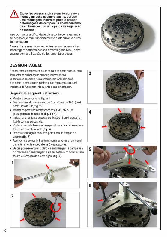
É preciso prestar muita atenção durante a montagem dessas embraiagens, porque uma montagem incorreta poderá causar deformações da campânula do mecanismo da embraiagem ou uma perda de regulação do mesmo.
Isso comporta a dificuldade de reconhecer a garantia de peças cujo mau funcionamento é atribuível a erros de montagem.Para evitar esses inconvenientes, a montagem e de-smontagem corretas dessas embraiagens SAC, deve ocorrer com a utilização de ferramenta especial.
DESMONTAGEM:É absolutamente necessário o uso desta ferramenta especial para desmontar as embraiagens autorreguladoras (SAC).Se tentarmos desmontar uma embraiagem SAC sem essa ferramenta, a embraiagem perderá a sua regulação e causará problemas de funcionamento durante a sua remontagem.
Seguire le seguenti istruzioni:● Montar a pega como na figura 1● Desparafusar do mecanismo os 3 parafusos de 120° (ou 4 parafusos de 90°, fig. 2).● Montar os parafusos correspondentes M6, M7 ou M8 (espaçadores) fornecidos (fig. 3 e 4).● Instalar a ferramenta especial de fixação (3 ou 4 braços) e fixá-la com as porcas M8.● Rodar a pega da ferramenta especial para fixar totalmente a tampa de cobertura mola (fig. 5).● Desparafusar agora os outros parafusos de fixação do volante (fig. 6).● Remover as porcas M8 da ferramenta especial e, em segui da, a ferramenta especial e os 3 espaçadores.● Agora pode-se erguer o platô da embraiagem, a campânula do mecanismo embraiagem está em batente no volante, isso facilita a remoção da embraiagem (fig. 7).
1
2
3
4
5
6
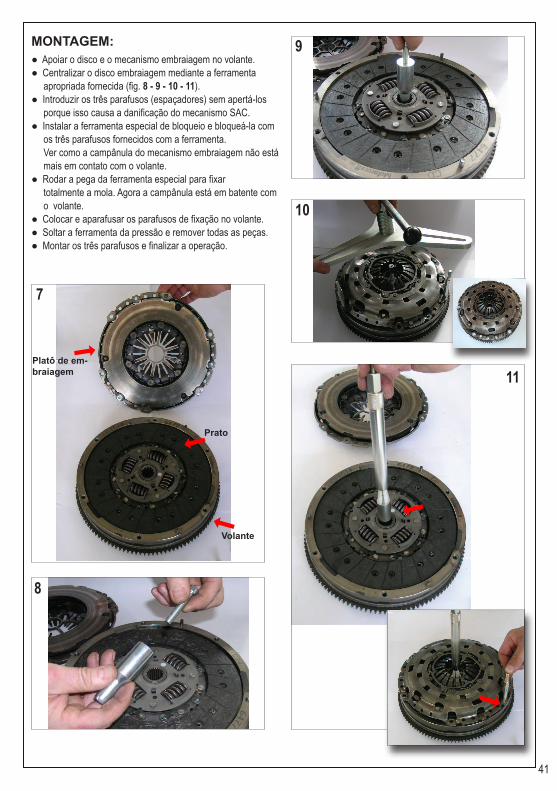
41
MONTAGEM:● Apoiar o disco e o mecanismo embraiagem no volante.● Centralizar o disco embraiagem mediante a ferramenta apropriada fornecida (fig. 8 - 9 - 10 - 11).● Introduzir os três parafusos (espaçadores) sem apertá-los porque isso causa a danificação do mecanismo SAC.● Instalar a ferramenta especial de bloqueio e bloqueá-la com os três parafusos fornecidos com a ferramenta. Ver como a campânula do mecanismo embraiagem não está mais em contato com o volante.● Rodar a pega da ferramenta especial para fixar totalmente a mola. Agora a campânula está em batente com o volante.● Colocar e aparafusar os parafusos de fixação no volante.● Soltar a ferramenta da pressão e remover todas as peças.● Montar os três parafusos e finalizar a operação.
7
8
9
10
11
Platô de em-braiagem
Volante
Prato

42
● Tampa com rosca de proteção rosca interna● 2 elementos de centragem / tensão para o rolamento guia ou o furo do eixo motor● Centrador com guia e elemento de tensão● 6 diferentes buchas cónicas para alargar os 2 elementos de centragem / tensão● 3 pinos de centragem de desaparafusamento com vários diâmetros para o rolamento guia
CENTRAGEM DISCO EMBRAIAGEM:Para uma montagem correta da transmissão e umfuncionamento correto da embraiagem a centralização dodisco é fundamental.Uma centragem correta consiste, durante as fases demontagem, na introdução cuidadosa do centrador dodisco embraiagem. Dessa forma reduz-se o risco de danificação do disco embraiagem.
POSSÍVEIS UTILIZAÇÕES DO PINO DE CENTRAGEM UNIVERSAL:O centrador universal foi projetado para uma aplicação universal em todos os automóveis. Normalmente está um rolamento de guia no furo do eixo motor cujo diâmetro interno é mais pequeno daquele do cubo.A particularidade deste centrador é que pode ser utilizado também quando falta o rolamento de guia.Nesses casos o diâmetro interno do furo da árvore motor pode ser mais grande daquele do cubo.
A escolha do pino de centragem / centrador a utilizar é em função do diâmetro interno do rola-mento de guia / furo do eixo motor, e da distância entre o rolamento guia / furo do eixo motor e o perfil do cubo do disco embraiagem.É possível utilizar os vários componentes combinando-os entre si para encontrar o pino de centragem apropriado.Se não for utilizado nenhum pino de centragem aparafusar a tampa com rosca de proteção da rosca interna, de forma a proteger a rosca contra a sujeira e possíveis danos.Definir os elementos de centragem e tensão a utilizar segundo a altura da guia do eixo motor e do cubo do disco embraiagem.

43
HASZNÁLATI ÚTMUTATÓ HUSPECIÁLIS KUPLUNGTÁRCSA KÖZPONTOSÍTÓ SZERSZÁM KISZERELÉS, KÖZPONTOSÍTÓ SZERSZÁMMA
KOMPONENSEKBeta Kód Leírás Beta Kód Leírás
VN952 Tengelyágy előre rögzített csavarral VN933 Központosító Ø 15
VN949 Elülső központosító Ø11,85 VN927 Központosító Ø 15/23
VN950 Elülső központosító Ø13,85 VN938 Központosító Ø 15/26.5 BMW kuplunghoz
VN951 Elülső központosító Ø14,85 VN928 Központosító Ø 15/28VN943 Kúpos központosító Ø15x30 VN929 Központosító Ø 15/34VN944 Kúpos központosító Ø15x40 VN934 Központosító Ø 16VN945 Kúpos központosító Ø15x67 VN935 Központosító Ø 17VN946 Kúpos központosító Ø15x75 VN936 Központosító Ø 18VN947 Kúpos központosító Ø18x67 VN937 Központosító Ø 19
VN948 Központosító Ø15,5 OR tartóe-lemmel VN925 M6 csap
VN948+VN955+VN956+VN953
Kúpos központosító Ø18x75 VN924 M7 csapKözpontosító Ø19,8 OR tartóe-lemmel VN923 M8 csap
Fémcsúcs Ø17,8 VN922 Tágító Központi csavar M8x170 VN930 Hab gyanta Ø 12
VN920 3 karos platni VN942 Központosító nyél Ø 20
VN921 4 karos platni VN940 Gömb alakú markolattal ellátott nyél Ø 12
TCE csavar 8x45 VN941 Rögzített nyél Ø 20VN931 Központosító Ø 12 VN926 MarkolatVN932 Központosító Ø 14 VN939 Lyuggatott csap

44
HASZNÁLATI ÚTMUTATÓ HU
Manapság egyre több gépjárműbe kerül beszerelésre SAC (Self Adju¬sting Clutch) típusú kuplung, az alábbiakban néhány ilyen típust sorolunk fel:
Márka ModellAlfa romeo 147 - 159 - 166 - Brera - SpiderAudi A3 - A4 - A6 - A8 - TTBmw 320 - 330 - 520 - 530Citroën C-CrosserFiat Ulisse - Croma - Ducato - Bravo - StiloFord Mondeo - Galaxy - Transit - S-Max - Focus C-MaxHyundai H-1 - I30 - Santa Fè - Sonata - TusconLancia Delta - Thesis - PhedraMercedes C - E - CLS - S - CLK - SLK - SLMitsubishi Grandis - OutlanderOpel VivaroPeugeot 4007Renault Espace IV - Laguna - Laguna II - Laguna III - Trafic II - Vel SatisSeat Altea - Leon - Toledo IISkoda Octavia - SuperbVauxhall Vivaro
Volkswagen Eos - Golf IV - Golf V - Golf V Plus - Jetta II - Multivan T5 - Passat - Passat CC - Scirocco - Touran - Transporter V
Volvo Volvo S40 II - V50
FELHASZNÁLÁS:Ezek a kuplungok, úgy nevezett ön-beállító kuplungok, mivel egy speciális mechanizmusnak köszönhetően automa-tikusan állítják be magukat, korrigálva a kuplung elhasználódásából adódó üres járatot. Ez a szerkezet folyamatos semlegesítő hatást gyakorol, megnövelve így a kom-fort érzetet és a kuplung élettartamát.
A SAC típusú kuplungokat, a mechanizmusra szerelt 2 vagy 3 sárga rugóról ismerheti fel.

45
A beszerelés alatt különleges figyelmet kell fordítani az ilyen típusú kuplungok felszerelésére, mivel a helytelen besze-relés kárt okozhat a kuplung szerkezet foglalatában vagy negatívan befolyásol-hatja annak beállítását.
Ilyen esetekben a helytelen beszerelésből szár-mazó károkat nehezen fedi a garancia. Az ilyen kellemetlen esetek elkerülése végett, a SAC típusú kuplungok ki- és beszerelését speciális szerszámokkal kell elvégezni.
SZÉTSZERELÉS:Fontos, hogy az önbeállító kuplungokat (SAC) ezzel a speciális szerszámmal szerelje fel. Abban az esetben ha egy SAC típusú kuplungot e szerszám nélkül szerelünk szét, az elveszti eredeti beállítását és komoly problémákat okozhat a visszaszerelés során.
A következő lépéseket kell betartani:● Szerelje fel a markolatot az 1.kép szerint● Csavarozza ki a szerkezet 3 csavarját 120° fokban (vagy 4 csavart 90° fokban, 2. kép)● Csavarozza fel a kiszereléshez tartozó M6, M7 vagy M8 (távtartó) típusú csavarokat (3 és 4 kép).● Szerelje fel a speciális rögzítő elemet (3 vagy 4 karú) és rögzítse M8 anyával.● Fordítsa el a speciális szerszám karját és rögzítse a rugók fedőjét (5. kép).● Most rögzítheti a kormány többi rögzítő csavarját is (6. kép).● Távolítsa el a speciális szerszámról az M8 anyát, majd magát a szerszámot végül pedig a 3 távtartó csavart.● Most megemelheti a tárcsaszorító tányért, a kuplung szerkezet foglalata a kormányhoz csatlakozik, ez megkön nyíti a kuplung eltávolítását (7. kép).
1
2
3
4
5
6

46
BESZERELÉS:● Támassza a tányért és a kuplung szerkezetet a kormánynak.● A kiszerelésben lévő megfelelő szerszám segítségével állítsa középre kuplungtárcsát (8 - 9 - 10 – 11. kép).● Helyezze be a három (távtartó) csavart de ne szorítsa meg őket, az megrongálhatná a SAC mechanizmust ● Szerelje fel a rögzítő szerszámot és rögzítse azt a kiszerelé sben található három záró csappal Megfigyelhető, hogy ekkor a kuplung szerkezet foglalata nem támaszkodik már a kormányra.● Fordítsa el a speciális szerszám nyelét és rögzítse a rugót. A foglalat most a kormányra támaszkodik. ● Helyezze be és rögzítse a kormány rögzítő csavarjait.● Távolítsa el a nyomási és minden más szerszámot.● Rögzítse a három csavart és fejezze be a munkálatokat
7
8
9
10
11
Tárcsaszorító
Kormány
Tányér

47
● Belső csavarmenet menetes védőkupak ● 2 központosító/rögzítő elem a sín betéthez vagy a főtengely furatához ● Központosító bevezetője és rögzítő elem ● 6 különböző kúpos vezetőék a központosító/ rögzítő elemek tágításához ● 3 központosító és eltávolító csap, különböző átmérőkkel és sín betéttel
A KUPLUNGTÁRCSA KÖZPONTO-SÍTÁSA:A tárcsa helyes központosítása elengedhetetlen feltétele a hajtómű helyes beszereléséhez és a kuplungtárcsa helyes működéséhez.
A helyes központosítás azt jelenti, hogy a beszerelési mun-kálatok folyamán, kuplungtárcsa központosító szerszámot nagyon pontosan a helyére illesztjük. Így elkerülhető a kuplungtárcsa sérülése
AZ UNIVERZÁLIS KÖZPONTOSÍTÓ CSAP EGYÉB FELHASZNÁLÁSA:Az univerzális központosító arra lett kifejlesztve, hogy min-denfajta járművön, univerzálisan legyen használható. Általában a főtengely furatában egy sín betét található, amelynek átmérője kisebb, mint a csonk. A központosító különleges tulajdonsága, hogy akkor is felha-sználható ha a sín betét esetleg hiányozna. Ebben az esetben, a főtengely furatának átmérője meghala-dhatja a csonk méreteit.
A felhasználandó központosító csap / központo-sító szerszám kiválasztása az alapján történik, hogy mekkora a csapágybetét átmérője / a főtengely furatának átmérője, illetve a csapágy-betét / főtengely furata közti távolság, és milyen a kuplung tárcsa csonkjának profilja. A különböző szerszámokat egymással kombinál-va is használhatja, annak érdekében, hogy a legjobb központosító csapot tudja felhasználni. A nem használ fel központosító csapot, ak-kor rögzítse a belső csavarmenet menetes védőkupakját, így megvédi a menetet a sérüléstől vagy a kosz lerakódásától.A központosító és rögzítő elemeket a főtengely sínjének és a kuplungtárcsa csonkjának magas-sága alapján kell kiválasztani.

BETA UTENSILI S.p.A.via Alessandro Volta, 18 - 20845 Sovico (MB) ITALY
Tel. +39 039.2077.1 - Fax +39 039.2010742www.beta-tools.com - [email protected]