141' (43.00 m) on-board tip height full power four … · full power four-section boom rated...
TRANSCRIPT
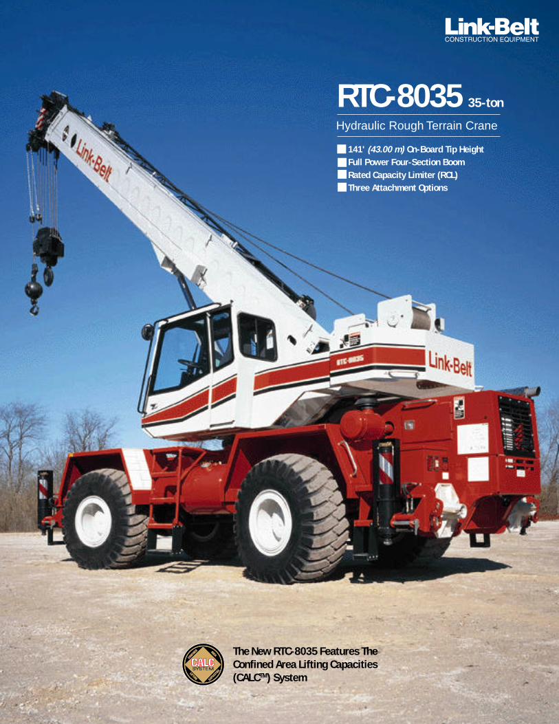
141' (43.00 m) On-Board Tip HeightFull Power Four-Section BoomRated Capacity Limiter (RCL)Three Attachment Options
Hydraulic Rough Terrain Crane
RTC-8035 35-ton
The New RTC-8035 Features TheConfined Area Lifting Capacities(CALCTM) System

The New RTC-8035 hydraulic rough terrain crane features unmatched innovations suchas the Confined Area Lifting Capacity System (CALCTM), a revolutionary fibrous compositecab – the ULTRA-CABTM, piston motor winches, and integral rated capacity limiter (RCL).
Additional Cab Features Include:• Tilting steering column for easy cab entering/exiting.• Automotive style windshield and large side window
provides operator with 25% more glass area.• Dash-less design for superior visibility.• Sliding right side and rear windows and swing-up roof
window provide excellent ventilation.• Large sweep electric wipers.
An Office With A Big View....A major step forward in the construction equipmentindustry, the new environmental ULTRA-CAB found onthe RTC-8035 is molded from an LFC•2000 constructionprocess featuring laminated fibrous composite material.Laminated fibrous composites are a hybrid class ofcomposites with lamination techniques. The layers offiber-reinforced material are built up with the fiberdirections of each layer typically oriented in differentdirections to add strength and stiffness.
This fibrous composite technology offers superior advan-tages over steel in sound reduction with sound levels one-half as loud as conventional cabs. This fibrous compositematerial, while eliminating corrosion, also adds dimen-sional stability and allows modern styling techniques tobe utilized including molded radii and ribs. Designed
with the operator in mind, the RTC Seriescab features:
Fabric Seat Six-way adjustable seat withheight-adjustable armrests.
Hydraulic Control Levers Armrest mounted,responsive dual axis controllers stan-
dard. Single axisavailable.
Lift-Up Armrest Leftarmrest lifts up out ofthe way providingoutstanding operatorease in entering orexiting the cab. For
safety, all control functionsbecome inactive when the
armrest is in raised position.
Backlighted Gauges Corner post mounted.
Overhead Console with switches for outrigger controls,lights, fan, and swing park brake.
Bubble Level Standard sight level mounted on sideconsole.
Single Foot Pedal Control for simultaneous extension orretraction of power boom sections.
Ducted Air through automotive style directional vents.
Comprehensive Instrumentation Corner post mounted gaugesmonitor hydraulic oil temperature, air pressure, fuellevel, water temperature, oil pressure and voltage.Converter oil temperature gauge mounted in side console.
Integral Rated CapacityLimiterThis “LMI” system aids the operatorin safe and efficient operation bycontinuously monitoring boomlength, boom angle, head height,radius of load, machine configura-tion, allowed load, and percent ofallowed load. This Microguard 434graphic audio-visual warning systemfeatures improved access time,improved radio frequency shielding,a new display panel with large liquidcrystal alphanumeric display, totalsystem override capabilities toprovide for rigging requirements and an expandedmemory which provides capacity information on allpossible lift configurations.
An exclusive new feature available on the RTC-8035 is theOperator Defined Area Alarm. By setting two points, theoperator creates an imaginary vertical plane to maintain asafe working distance from nearby obstacles. Should theoperator attempt to operate the crane beyond the plane,the RCL will sound an alarm.
A graphic display bar, positioned near the top of thewindshield for optimum viewing during crane operation, isavailable. This bar constantly alerts the operator of thecurrent lift capacity situation through a series of green
(within capacity range), yellow (approaching 90% chartlimit), and red (100% of chart limit) lights.
State-of-the-Art Wire HarnessThe RTC-8035 has automotive-type wire harnesses
with sealed relays and connectorsthroughout for outstanding long termreliability. In addition, all wires havea flame retardant, polyethyleneinsulation, resulting in a higher heatresistant wiring system.
The Link-Belt RTC-8035....a combination of precision and comfort.

Superior Controllability and Reliability
Jobsite Maneuverability Maneuveringthe RTC-8035 on the job site is made easierwith independent controls for steering.Steering modes include independent frontsteer, four wheel coordinated steer and“crab” steering for tight job site situations.
Power Train Utilizing a standardCummins engine and Clark transmissiontranslates to maximum parts availabilityas these components are common to manydrive trains used in the construction industry.The Cummins 152 horsepower (113 kW) engineis coupled to a Clark 6-speed forward, 6-speedreverse electric powershift transmission.
Gear Pumps One main 2-section gear-type pumpand one single gear-type pump provide hydraulicpower. A mechanical disconnect on the 2-sectionpump saves wear on the hydraulic system andreduces the load placed on the engine whentravelling long distances.
Added Value Carrier Features Large grabhandles and steps strategically located around thenew RTC-8035 provide superior accessibility tocarrier deck areas and engine for routine mainte-nance and service. Safety strips adhered on top ofthe deck and fenders provide a non-slip surfacefor maintenance personnel.
A standard oversize storage compartment is idealfor tools, slings, and accessories. Additionally,lightweight aluminum outrigger floats with a"quick latch" feature, rigid front axle for greaterstability in rough terrain, air over dual hydraulicdisc service brakes for improved braking, springapplied/air released emergency brakes, air serviceports, and complete light package continue Link-Belt rough terrain crane standards.... superiorcustomer benefits for superior customer value.A driver controlled differential lock on both axlesis available for maximum traction.
The RTC-8035 with 141' (43.00 m)of on-board tip height is specificallydesigned to give contractors andrental house companies the bestequipment value in the 35-tonRT class.
Two-Part Paint Coating SystemSetting another new industry standard,Link-Belt is utilizing a two-part coatingtechnology coupled with a pre-assemblypaint process to provide the finest qualitycoating system available today. This newcoating technology provides superioradhesion and abrasion resistance. Inaddition, because all parts are paintedbefore assembly, 100% coverage of eachpart is realized, virtually eliminatingcorrosion bleed-through that is commonwith old paint processes.
The combination of this paint’s superiorabrasion resistance and the pre-assemblypaint technique dramatically enhancesthe aesthetic appealof the final machineas nuts, bolts, hoses,and a whole multi-tude of piece partsare no longer painted.As a result, paintchipping, cracking,and paint deterior-ation is substantiallyreduced when service workand disassembly is required.

... Traditional Link-Belt Standards!Superior Hydraulics...for smooth, precise control
Piston Motor Hydraulic Hoist SystemDelivers superior hoisting to the35 ton (32 metric ton)hydraulic rough terraincrane class The stan-dard load hoistsystem consistsof a 2M mainwinch with two-speed motor andautomatic brakefor power up/downmode of operation. A bi-directionalpiston-type hydraulic motor, driven through a plan-etary reduction unit provides precise, smooth loadcontrol with minimal rpm. Asynchronous, paralleldouble cross-over grooved drums minimize ropeharmonic motion, improving spooling and increasingrope service life. Rotation resistant rope is standard.
A two-speed 2M auxiliary winch is available. On thetwo-winch machines, an independent winch functionlockout is provided. When this mode is selected, theoperator won’t inadvertently operate a winch whichhas been shut down preventing a two-blocking or rope“bird nesting” situation.
Matched sizes of main and auxiliary winches provideequal maximum available line pulls of 10,360 lbs.(4 699 kg) and maximum line speeds of 473 f.p.m.(144 m/min.) on 10-5/8" (.27 m) root diametergrooved drums.
State-Of-The-Art Oil Seal TechnologyThe RTC-8035 features improved seals on boomhoist,boom extend/retract, and outrigger jack cylinders.This new ‘redundant’ oilseal technology incorpo-rates 3 rod sealingsurfaces versus one ortwo found on competi-tive models. This newseal design is highlyresistant to side loadingand pressure spikes foroutstanding sealing
performanceand, whenincorporated with full O-ring face sealtechnology used throughout the machine,leads to an environmentally dry system.
Multi-Function Control For greater productivityand control, the three pump hydraulic circuit allowssimultaneous function of boomhoist, winch and swing....setting the standard in the 35-ton (32 metric ton) class.
Simplified Routings The new RTC-8035 incorpo-rates simplified hydraulic routings for easy access.Fittings and connections are staggered where necessaryfor quick and easy servicing.
Serviceability Standard quick disconnects installedat various locations in the hydraulic system allow thehydraulic pressure to be quickly and easily checked withLink-Belt’s exclusive diagnostic gauge kit (optional).

Industry First Innovations…Confined Area Lifting Capacities (CALCTM) System
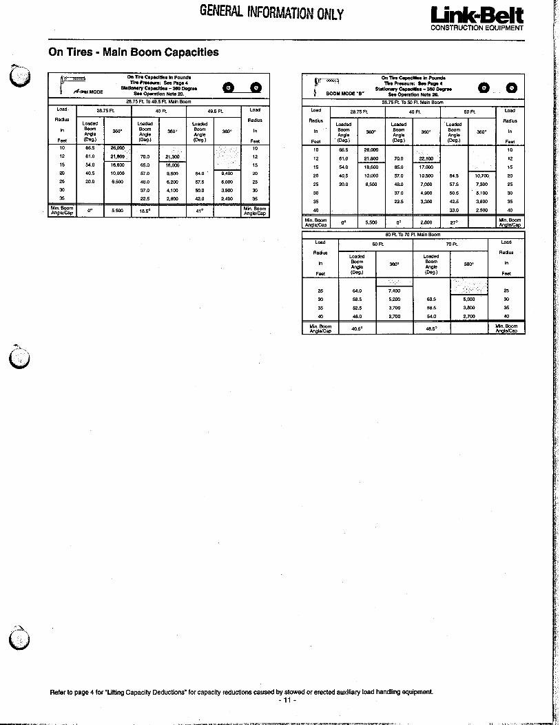
The new RTC-8035 rough terrain crane is specifically designed to allow contractors to workin confined work areas where full outrigger extension is not possible. The CALC systemprovides the operator with three outrigger positions (full extension, intermediate, and fullyretracted). Outriggers may be extended to an intermediate position where working area islimited or, in extremely tight quarters, lifts can be made with outriggers fully retracted. Inthe fully retracted outrigger mode, lift capacities are significantly improved over the ‘on tires’configuration because of the ability to fully level the machine, no matter the ground conditions.
Fully Extended Outriggers20' 6-1/4" (6.25 m) spread
Intermediate Extended Outriggers14' 8" (4.47 m) spread
Fully Retracted Outriggers8' 8-1/4" (2.64 m) spread
Full Power Boom With Exclusive A-max ModeA customer benefit which enhances the 8035’sperformance and provides the operator thecapability to match the crane’s configurationto specific jobsite conditions. For maximum tipheight the basic boom extension mode offers afull power, synchronized mode of telescoping allsections proportionally to 91' 0" (27.74 m). Toenhance performance, the exclusive A-maxmode (or mode ‘A’) extends only the inner midsection to 49' 6" (15.09 m) offering substantiallyincreased capacities for in-close, maximumcapacity picks. Basic boom extend mode Exclusive A-max boom
extend mode
The outrigger position levers (located on the outrigger boxes) are easily applied.Once the levers are engaged, the operator can set the crane in the intermediate orfully retracted outrigger mode without having to leave the cab.
Under full extension, the outrigger beams extend to a wide 20' 6-1/4" (6.25 m)spread centerline to centerline. Centerline to centerline spread dimension forintermediate outriggers measures 14' 8" (4.47 m) and 8' 8-1/4" (2.64 m) for fullyretracted... narrow enough to fit in extremely tight working areas but with thestability and capacities provided by being set on outriggers.
A thorough, easy-to-read crane rating manual gives the operator comprehensivecapacities covering the three outrigger positions with all attachments plus ‘pickand carry’ capacities.
The CALC System... another industry innovation from Link-Belt designed forexceptional customer value.

Patented boom design
Link-Belt Construction Equipment Compan y Lexington, KentuckyA unit of Sumitomo Construction Machinery Co., Ltd. All rights reserved. Copyright 1997.® Link-Belt is a registered trademark. We are constantly improving our products and therefore reserve the right to change designs and specifications. Litho in U.S.A. 1/97 #4203
Embossed SidewallStiffeners Increasessidewall stiffness.
Sidewall DesignConcept Not only dothe embossmentsincrease sidewallstiffness, but because oftheir placement theynaturally transferstresses uniformly tothe high strength anglechords (corners) — aconcept derived fromLink-Belt lattice boomtechnology.
Boom Wear Shoes Boomtelescope sections are sup-ported by adjustable wear shoesboth vertically and horizontally.
Angle Chords 100,000 psi (689.5 MPa) highstrength steel angle chords are precision ma-
chined for boom sidewall overlap.This design allows all interior andexterior boom welds to be offset orstaggered for maximum structuralintegrity.
Time Proven Boom Design Overtwo decades and thousands ofhydraulic crane booms later, Link-Belt’s exclusive, patented design isunchanged, state-of-the-art — beforeits time; providing superior capaci-ties, tip heights and reliability.
It is true testimony to Link-Belt’sengineering design achievement thatthis design concept is being imitatedtoday for optimum performance.
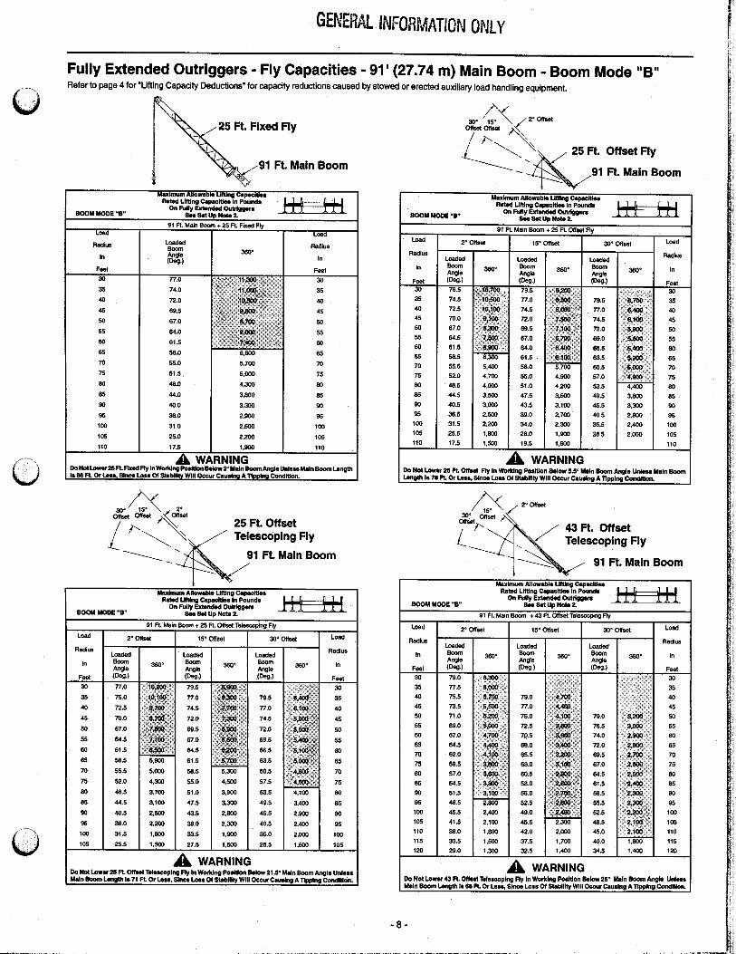
Attachment Flexibility• Full power, fully synchronized 28' 9" – 91' 0" (8.76 m – 27.74 m)
four-section boom.• 25' 0" (7.62 m) fixed stowable one piece lattice type fly.• 25' 0" (7.62 m) offsettable (2°, 15°, or 30°) stowable one piece
lattice type fly.• 25' 0" – 43' 0" (7.62 m – 13.10 m) offsettable (2°, 15°, or 30°)
stowable lattice type fly with telescoping box section.
Added Value Attachment Features• Hammerhead Boom Nose Allows the operator to
work at high boom angles without fouling wirerope.
• Quick Reeve Boom Head Allows rope to be easilyreeved over boom head without removing ropesocket from wedge.
• Deflector Rollers Rollers prevent prematurewire rope wear when working at low boomangles.
• Lightweight Nylon Head Sheaves Reduce overallmachine weight and increase lift capacities.
• Available Auxiliary Lifting Sheave Can be used forquick lifts with one or two parts of line whenthe boom head has multiple reeving. And itdoes not have to be removed when fly iserected in working position.
Embossed Sidewall StiffenersWith No-Weld CornersBoom Concept The arrangement of high strength angle chords (corners)
with high formability steel sidewall (embossments) places the most steelat corners where maximum stress is concentrated. The result:
maximum strength with minimum weight.
Stowable Attachments Swing-away lattice flys are easily storedfor transportability or can be removed to meet specific road laws.
(pick up Boss)Patented Design
THE ORIGINAL EMBOSSED BOOM STIFFENER
NO WELDS IN HIGH STRESS CORNERS
� 1 �
RTC-8035Hydraulic Rough Terrain Crane
35-ton (31.5 metric ton)
Litho in U.S.A. 9/96
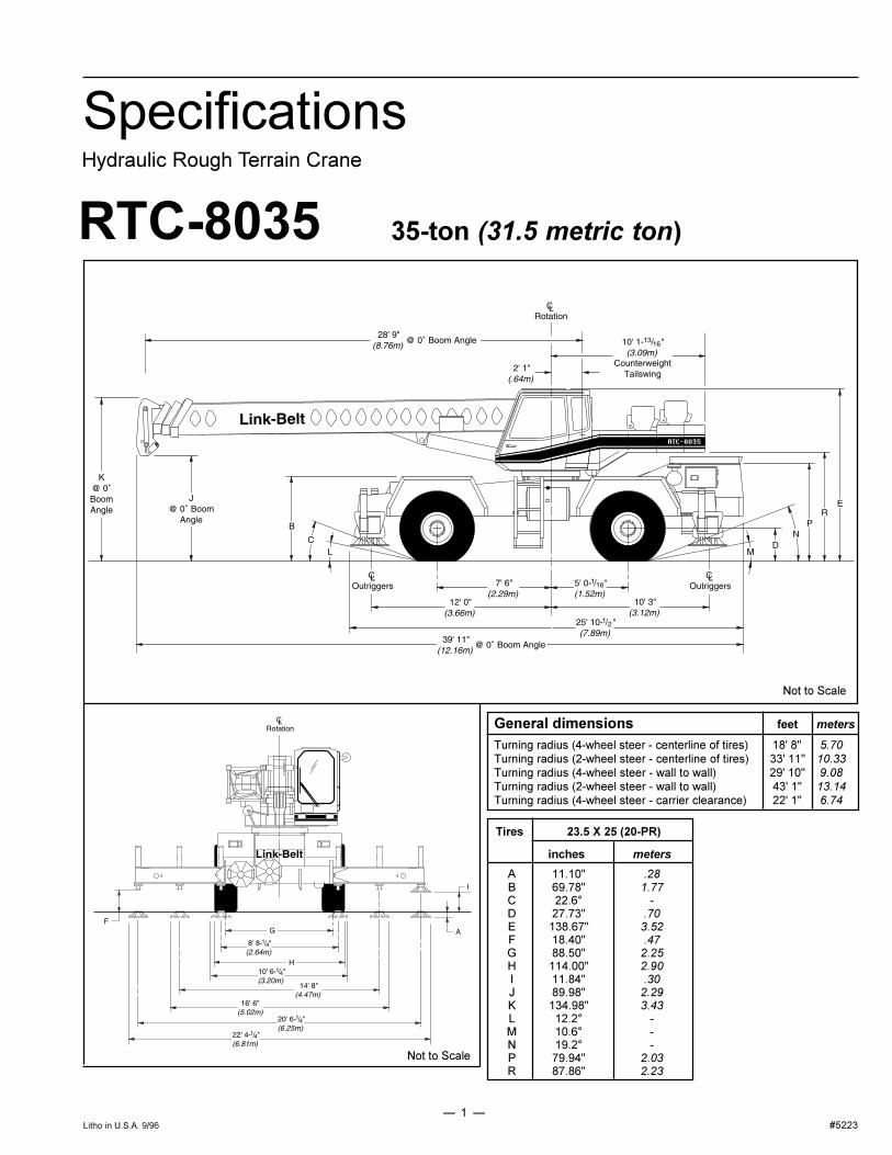
Specifications
General dimensions feet meters
Turning radius (4-wheel steer - centerline of tires) 18' 8" 5.70Turning radius (2-wheel steer - centerline of tires) 33' 11" 10.33Turning radius (4-wheel steer - wall to wall) 29' 10" 9.08Turning radius (2-wheel steer - wall to wall) 43' 1" 13.14Turning radius (4-wheel steer - carrier clearance) 22' 1" 6.74
Tires 23.5 X 25 (20-PR)
inches meters
A 11.10" .28B 69.78" 1.77C 22.6° -D 27.73" .70E 138.67" 3.52F 18.40" .47G 88.50" 2.25H 114.00" 2.90I 11.84" .30J 89.98" 2.29K 134.98" 3.43L 12.2° -M 10.6° -N 19.2° -P 79.94" 2.03R 87.86" 2.23
Not to Scale
Not to Scale
#5223

� 2 �
UpperstructureBoom
Patented Design. All boom section sideplates have diamond shaped impressionsfor superior strength to weight ratio and100,000 p.s.i. (689.5 MPa) steel anglechords for lateral stiffness. Boom tele-scope sections are supported by wearshoes both vertically and horizontally toprevent metal to metal contact.
Microguard 434, Rated CapacityLimiter - Standard; Graphic, audio-visualwarning system built into corner post withanti-two block and function limiters.Operating data available includes boomlength, boom angle, head height, radius ofload, machine configuration, allowed load,actual load and percent of allowed load.Presettable alarms for maximum andminimum boom angles, max. tip height,max. boom length, swing left/rightpositions. Operator defined area alarm isalso provided. Anti-two block weightdesigned for quick reeve of hookblock.
Optional; Load rating bar graph for quickoperator reference.
Standard Boom - 28' 9" - 91' 0" (8.76 -27.74 m) four-section full power boom.Two mode boom extension - Basic mode(or mode 'B') is the full power, synchro-nized mode of telescoping all sectionsproportionally. The exclusive A-max mode(or mode 'A') extends only the inner mid-section to 49' 6" (15.09 m) offeringincreased capacities for in-close, maxi-mum capacity picks.
Boom head - Four 10-5/8" (0.27 m) rootdiameter nylon sheaves handle up to 8parts of wire rope. Rope dead end lugsprovided on each side of boom head.Easily removable wire rope guards arestandard. Boom head designed for quickreeve of hookblock.
Auxiliary lifting sheave - Optional;Single 10-5/8" (0.27 m) root diameternylon sheave with removable wire ropeguard. For use with one or two parts ofline off the optional auxiliary winch. Doesnot affect erection of fly or use of mainhead sheaves for multiple reeving.
Boom elevation - One Link-Belt designedhydraulic cylinder with holding valve andbushings in each end. Hand control forcontrolling boom elevation from -3° to +79.9°.
FlyOptional - 25' (7.62 m) fixed stowable onepiece lattice type.
Optional - 25' (7.62 m) offsettable (2°, 15°,or 30°) stowable one-piece lattice type.
Optional - 25' - 43' (7.62 m - 13.10 m)offsettable (2°, 15°, or 30°) stowablelattice type with telescoping box section.
Cab and ControlsEnvironmental ULTRA-CABTM ofLFC�2000 construction process featuringlaminated fibrous composite material;isolated from sound with acoustical fabricinsulation providing 82 dBA sound level,all tinted and tempered safety glasswindows. Sliding rear and right sidewindows and swing up roof window formaximum visibility and ventilation. Slide-by-door opens to 36" (0.91 m) width. 6-way adjustable operator's seat formaximum operator comfort. Hydrauliccontrol levers (joystick type) for swing,winches and boomhoist. Outriggercontrols conveniently located in overheadcontrol console; sight level bubble alsoprovided in upper cab. Foot controls forboom telescope, swing brake, travel brakeand engine throttle.
Cab instrumentation - Corner postmounted gauges for hydraulic oil tempera-ture, air pressure, fuel, tachometer, watertemperature, voltmeter and oil pressure.Convertor oil temperature gauge mountedin side console.
SwingBi-directional hydraulic swing motormounted to a planetary reducer for 360°continuous smooth swing at 3.6 r.p.m.
Swing parking brake - 360°, electric overhydraulic (spring applied, hydraulicreleased) multi-disc brake mounted on thespeed reducer. Operated by toggle switchin overhead control console.
Swing brake - 360°, foot operated,hydraulic applied disc brake mounted onthe speed reducer.
Travel swing lock - Standard; twoposition travel swing lock (pin device)operated from the operator�s cab.
Counterweight - Bolted to upperstructureframe. 9,750 lb. (4 422 kg) ctwt. onmachines with two hoist drums; 10,615 lb.(4 814 kg) ctwt. on one drum machines.
Hydraulic SystemMain pump - 2-section gear type pump.Combined pump capacity 75 gpm (283.8lpm). Torque converter mounted pumppowered by engine through a pumpdisconnect. Pump disconnect is engaged/disengaged from carrier. Section oneoperates winch circuit @ max. pressure of3,500 p.s.i. (246 kg/cm2). Section twooperates boom hoist and telescopecircuits @ max. pressure of 3,100 p.s.i.(218 kg/cm2).
Swing / outrigger / steering pump -Single gear-type pump, 18 gpm (68.13lpm) maximum. Torque converter mounted
pump powered by engine. Pump operatesat 2,500 p.s.i. (175 kg/cm²).
The three pump hydraulic circuit allowssimultaneous operation of the three maincrane functions (winch, boom hoist,swing) without any function interference.
Reservoir - 110 gallon (416.39 L)capacity. One diffuser for deaeration.
Filtration - One 10-micron filter locatedinside hydraulic reservoir. Accessible foreasy replacement.
Control valves - Five separate pilotoperated control valves allow simulta-neous operation of all crane functions.
Load Hoist SystemStandard - 2M main winch with two-speed motor, automatic brake andelectronic drum rotation indicator; powerup/down mode of operation. Bi-directionalpiston-type hydraulic motor, driventhrough a planetary reduction unit forpositive control under all load conditions.
Optional - Model 1M main winch with one-speed motor and automatic brake, powerup/down mode of operation.
Optional - Model 1M auxiliary winch withone-speed motor and automatic brake,power up/down mode of operation.
Optional - Model 2M auxiliary winch withtwo-speed motor and automatic brake,power up/down mode of operation.
Line pulls and speeds - Maximum linepull 10,360 lbs. (4 699 kg) and maximumline speed of 473 f.p.m. (144 m/min) onstandard 10-5/8" (0.27 m) root diametergrooved drum.
Additional Equipment -Standard
Fire extinguisher, seat belt, horn, domelight, mirrors, tilt/telescoping steeringwheel, electric windshield wiper/washer,rooftop window electric wiper, defrosterfan, backup alarm, audible swing alarm,cab-mounted work lights, and rotationresistant wire rope.
Additional UpperstructureEquipment - Optional
360° swing lock (meets New York Cityrequirements), single axis controls, dieselor hydraulic heater, air conditioning, 35-ton (31.77 metric ton), 15-ton (13.6 metricton), or 25-ton (22.7 metric ton) quickreeve hook blocks, 8-1/2-ton (7.71 metricton) hook ball, engine monitoring system,amber rotating beacon, boom floodlight,drum cable follower, and 3rd wrap drumindicator.

� 3 �
BrakesService - Air over hydraulic, disc typebrakes at each wheel end.
Parking/emergency - Disc caliper typespring applied, air released, fade resis-tant; cab controlled, mounted on frontaxle.
SteeringHydraulic two wheel, four wheel and�crab� steering: controlled from steeringwheel.
TransmissionClark three-speed two range power shifttransmission. Six speeds availableforward and reverse. Front axle discon-nect for two or four-wheel drive.
OutriggersThree position (fully extended, intermedi-ate and fully retracted) operation capabil-ity. Four hydraulic, telescoping beam andjack outriggers. Vertical jack cylindersequipped with integral holding valve.Beams extend to 20' 6-1/4" (6.25 m)centerline-to-centerline and retract towithin 9' 6" (2.90 m) overall width.Equipped with stowable, lightweight 22"(0.56 m) octagonal aluminum floats.Controls and sight level bubble located inupperstructure cab.
CarrierType
9' 6" (2.89 m) wide, 150" (3.81 m)wheelbase.
4 x 4 x 4 - (4-wheel steer, 4-wheel drive)Standard - For rough terrain with limitedturning area.
Frame - 100,000 p.s.i. (689.5 MPa) steel,double walled construction with integral100,000 p.s.i. (689.5 MPa) steel outriggerboxes.
AxlesFront - Standard; heavy duty
planetary drive/steer type.
Rear - Standard; heavy dutyplanetary drive/steer type.
Front/Rear - Optional; driver controlleddifferential lock for high traction.
SuspensionFront axle - Rigid mounted to frame.
Rear axle - Pin-mounted on welded steelbox cradle. Automatic hydraulic rear axleoscillation lock-out engages whenupperstructure rotates past 2-1/2° ofcenterline.
TiresFront and RearStandard - 23.5 x 25 (20-PR)
Earthmover type.
Confined Area Lift Capacities (CALC)System - Outrigger may be extended toan intermediate position for working inconfined areas. Extend position leverslocated on outrigger boxes allow theoutrigger beams to be fully extended orlimits them to intermediate position basedon the selected position.
Additional Equipment -Standard
Cab steps, front, side, and rear carriersteps, electronic controlled front axledisconnect, skid resistant finish on carrierdeck, front storage, fenders, pontoonstorage, full travel lighting package,throttle lock, hour meter, air chucks, andlifting/tie down lugs.
Additional Equipment -Optional
Differential lock on both axles, front andrear towing shackles, propane firedengine block heater, ether injectionpackage, air dryer, spare tires and rims,front and rear mounted pintle hooks,outrigger cover package, emergencysteering system, rear steer indicator, andcarrier mounted winch, 24 volt start andtire inflation kit.
Engine
Cylinders - cycleBoreStrokeDisplacementMaximum brake hpPeak torqueElectric systemFuel capacityAlternatorCrankcase capacity
Cummins 6BT 5.9
6 - 44.02" (102.1 mm)4.72" (119.9 mm)359 cu. in. (5 884 cm³)152 @ 2500 rpm400 ft. lbs. (542 J)12 volt75 gallons (284 L)130 amps17.3 qts. (16.4 L)
Travel speeds and gradeability
Maximum Gradeability Maximum tractive effort Gradeability Maximum tractive effort atSpeed at at stall at 1.0 mph 1.0 mph (1.61 km/h)
stall (1.61 km/h)mph km/h pounds kg pounds kg
Cummins
6BT 5.9 23.5 X 25 21.1 34.0 72.3% 38,240 17 346 47.0% 28,069 12 732
Engine Tires

� 4 �
Axle loads
Base machine with standard 28' 9" - 91' 0" Upper facing front(8.76 m - 27.74 m) four-section fullpower boom, 2M main winch with 2-speed Front axle Rear axle Front axle Rear axlehoisting and power up/down, 450'(137.16 m) 5/8" (16 mm) wire rope, 4x4x4 lbs. kg lbs. kg lbs. kg lbs. kg lbs. kgcarrier with Cummins 6BT 5.9 engine, 23.5X 25.0 tires, full fuel and counterweight. 57,785 26 210 25,323 11 486 32,462 14 724 20,321 9 217 37,464 16 993
Cold weather starting aids - propane heaterand ether injector 48 22 6 3 42 19 6 3 42 19
Tow shackles 39 17 18 8 21 9 18 8 21 9
Pintle hook, front 20 9 28 13 -8 -4 28 13 -8 -4
Outrigger cover package 110 50 52 24 58 26 52 24 58 26
Carrier mounted winch 686 311 923 419 -237 -108 923 419 -237 -108
Winch roller - front 76 34 -14 -7 90 41 75 33.5 1 .5
Winch roller - rear 76 34 -1 -.5 77 34.5 62 28 14 6
1M main winch -24 -11 6 3 -30 -14 -25 -11.5 1 .5
1M auxiliary winch -232 -105 17 8 -249 -113 -202 -91 -30 -14
2M auxiliary winch -210 -95 15 7 -225 -102 -183 -83 -27 -12
350' (106.7 m) wire rope on auxiliary winch 286 130 -24 -11 310 141 253 115 33 15
Hydraulic heater 110 50 22 10 88 40 66 30 44 20
Diesel heater 70 32 16 7 54 25 40 18 30 14
Fly brackets to boom base section forfly options 113 51 156 71 -43 -20 -66 -30 179 81
25' (11.34 m) fixed fly (stowed) 544 247 794 360 -250 -113 -359 -163 903 410
25' (11.34 m) offsettable fly (stowed) 1,002 455 1,492 677 -490 -222 -690 -313 1,692 768
25' - 43' (11.34 - 13.11 m) offsettable fly(stowed) 1,492 677 2,206 1 001 -714 -324 -1,013 -460 2,505 1 137
Floodlight on boom base section 4 2 7 3 -3 -1 -4 -2 7 3
35-ton hookblock to front bumper 780 354 1,108 503 -328 -149 - - - -
Hookball to front bumper 360 163 511 232 -151 -69 - - - -
Auxiliary arm 60 27 157 71 -97 -44 -109 -50 169 77
Upper facing rearG.V.W.1
Link-Belt Construction Equipment Company Lexington, KentuckyA unit of Sumitomo Construction Machinery Co., Ltd.® Link-Belt is a registered trademark. Copyright 1996. We are constantly improving our products and therefore reserve the right to change designs and specifications.
Note: All weights are ± 3%
Adjust gross vehicle weight & axle loading according to component weight.1
Tire
23.5 x 25 (20-PR)
Max. Axle Load @ 20 mph (32.7 km/hr)
33,000 lbs. (14 969 kg)