140-200-p pto-driven compressor kit installation … company, 125 hardman avenue south, south st....
TRANSCRIPT
Waterous Company, 125 Hardman Avenue South, South St. Paul, Minnesota 55075 USA (651) 450-5000 www.waterousco.com
140-200-P PTO-Driven Compressor KitInstallation Guide
Read through the installation instructions carefully.
NOTE: Instructions subject to change without notice.
F-1031, Section 3036 (Revised 10/12/11)
SECTION 1.INSTALLATION OVERVIEW .............................................................. 4SECTION 2. ...................................................................................................................... INSTALLING THE WATEROUS COMPONENTS ................................................... 5
A. PTO installation ......................................................................................... 6 B. Air compressor installation ........................................................................ 7
I. The Compressor .................................................................................. 7 II. Bolted to a bracket under the compressor body. ................................. 8 III. Using the mounting flange with a bracket ............................................ 11 IV. Compressor oil discharge outlet and flange ......................................... 12 V. Connecting the Compressor to the PTO .............................................. 13
C. Air Inlet and Filter ...................................................................................... 14 D. Air-oil reservoir (sump) installation ............................................................ 15 E. Optional Oil Check Valve .......................................................................... 16
I. Vertical Sump ....................................................................................... 17 II. T-Sump (Optional) ............................................................................... 18 III. Oil fill and sight glass ........................................................................... 18 IV. T-Sump Drain ....................................................................................... 19
F. Oil Temperature Gauge (all sumps) .......................................................... 20 G. Separator/filter installation ........................................................................ 21 H. Heat Exchanger (Cooler) Installation ........................................................ 22
I. Connecting the cooler water lines and wye-strainer ............................ 23 II. Wye Strainer for Cooler ....................................................................... 23
I. Hydraulic Filter Installation ........................................................................ 25 J. Auto-Sync Control System Installation ...................................................... 26
I. Manual valves ...................................................................................... 26 II. Electric Valves (Solenoids) .................................................................. 27
K. Balance Valve Installation ......................................................................... 28 SECTION 3. ...................................................................................................................... INITIAL POWER-UP ................................................................................................ 29
A. Post-Installation, Pre-Power up Safety Check .......................................... 29 B. Initial Compressor System Power-up ........................................................ 30
SECTION 4. ...................................................................................................................... INITIAL ADJUSTMENT OF THE AUTO-SYNC AIR BALANCING SYSTEM .......... 31
A. Electric Auto-Sync Initial Setup ................................................................. 31 I. UNLOAD Mode Initial Setting .............................................................. 31 II. FIXED Mode Initial Setting ................................................................... 33 III. AUTO Mode Initial Setting ................................................................... 34
B. Manual Auto-Sync Initial Setup ................................................................. 35 I. UNLOAD Mode Initial Setting .............................................................. 35 II. FIXED Air Initial Setting: ...................................................................... 36 III. AUTO Air Initial Setting: ....................................................................... 37
SECTION 5. ...................................................................................................................... SUGGESTED THIRD-PARTY COMPONENTS ...................................................... 39
A. Suggested components for CAFS discharges: ......................................... 39 B. Suggested Hose ....................................................................................... 40 C. Power Take-Off Suggestions .................................................................... 41
I. Compressor ......................................................................................... 41 SECTION 6. ...................................................................................................................... TROUBLESHOOTING GUIDE ................................................................................ 42
A. Troubleshooting - CAFS ........................................................................... 42 SECTION 7. ...................................................................................................................... Basic Driveline Installation Suggestions ................................................................. 67
A. U-Joint Operating Angles .......................................................................... 67 I. Reducing and Canceling Vibration ....................................................... 67
B. Single Plane and Compound U-Joint Operating Angles ........................... 68 I. Single Plane ......................................................................................... 68 II. Compound Angles ............................................................................... 70 III. True U-Joint Operating Angle .............................................................. 70 IV. Angle Size ............................................................................................ 70
C. Eliminating Compound Angle Induced Vibrations ..................................... 72 SECTION 8. ...................................................................................................................... CONDITIONAL 5-YEAR WARRANTY POLICY ...................................................... 76
F-1031, Section 3036 Page 2 of 76
Warnings, Cautions, and Notes Warning: A warning alerts you to a procedure, practice or condition that may result in death or long
term injury to personnel or destruction of equipment.
Caution: A caution alerts you to a procedure or condition that may result in serious damage to equipment or its failure to operate as expected
Note: A note points out important information. Failure to read the note may not result in physical
harm to personnel or equipment. It may waste time and money. ATTENTION: Defects in replacement part(s), component(s) or product(s) manufactured by others and furnished by WATEROUS is understood that the only warranty provided for such replacement part(s), component(s) or product(s), shall be the warranty provided by the manufacturer of said replacement part(s), component(s) or product thereof which, if assignable, WATEROUS will assign to Buyer, if requested by Buyer. Defects in replacement part(s), component(s) or product(s), not furnished by Waterous, but suggested in the installation guide, are the responsibility of the installer and the manufacturer of said replacement part(s), component(s) or product(s). Waterous will not be responsible for any replacement part(s), component(s) or product(s) that are not furnished or purchased from Waterous. WARRANTY INSERT (from last page) The aforesaid warranty excludes any responsibility or liability of WATEROUS for:
c) any product or part, altered, modified, serviced or repaired other than by WATEROUS, without its prior written consent; and
d) the cost of dismantling, removing, transporting, storing, or insuring the defective product or part and the
cost of reinstallation. Revision History
Revision Date Issued Comments 1 05/13/03 Original Release 2 11/01/04 2nd Release
2.1 12/14/04 2nd Release, 1st Revision 3 3/15/06 3rd Release 4 4/26/07 Reformat, new logo, updated pics, more tables 5 1/22/08 Added suggested hose info, chged fig 32-35 3/9/09 Updated Air schematic
6 6/16/10 Added warranty 7 10/12/11 Clarified text on pg 21 , added dimensions to Fig
24 & 25 Disclaimer: These instructions are guidelines only and in no way meant to be definitive. During installation, standard safety precautions and equipment should be used where appropriate. Because the tools used and the skill/experience of the installer can vary widely, it is impossible to anticipate all conditions under which this installation is made, or to provide cautions for all possible hazards. Proper installation is the responsibility of the purchaser. All bolts, setscrews, and belts must be checked prior to start-up AND after the initial operation. Damages due to poor installation are the responsibility of the installer. Waterous reserves the right to make modifications to the system without notice

F-1031, Section 3036 Page 3 of 76
Figure(s)
Figure 1 Universal mounting bracket ........................................................................................................... 9 Figure 2 Compressor mounting flange with a bracket ............................................................................... 11 Figure 3 Compressor oil discharge outlet and flange ............................................................................... 12 Figure 4 Companion Flange Adapter or equivalent. .................................................................................. 14 Figure 5 Sump height to Compressor ........................................................................................................ 15 Figure 6 Optional Oil Check Valve ............................................................................................................. 16 Figure 7 T- Sump (Optional) ....................................................................................................................... 18 Figure 8 Sight Gauge .................................................................................................................................. 19 Figure 9 Temperature sender, on Sump ................................................................................................... 20 Figure 10 Heat Exchanger (Cooler) ............................................................................................................ 22 Figure 11 Wye Strainer ............................................................................................................................... 24 Figure 12 Wye-strainer installed, with cleanout valve. .............................................................................. 24 Figure 13 Clean Strainer ............................................................................................................................ 24 Figure 14 Dirty Strainer .............................................................................................................................. 24 Figure 15 Manual Auto-sync ...................................................................................................................... 26 Figure 16 Electric Auto-sync ...................................................................................................................... 27 Figure 17 Manual Auto-sync panel ............................................................................................................ 35 Figure 18 90º Air Inlet ................................................................................................................................ 35 Figure 19 Vertical Air Inlet .......................................................................................................................... 36 Figure 20 Typical CAFS Discharge ........................................................................................................... 39 Figure 21 Basic CAFS Schematic ............................................................................................................. 45 Figure 22 200-P Tee Sump ........................................................................................................................ 46 Figure 23 140-P Tee Sump ........................................................................................................................ 47 Figure 24 200-P Vertical Sump .................................................................................................................. 48 Figure 25 140-P Vertical Sump .................................................................................................................. 49 Figure 26 Compressor Main Dimensions .................................................................................................. 50 Figure 27 Companion Flange, 32mm Bore ................................................................................................. 51 Figure 28 6" Tee Sump .............................................................................................................................. 52 Figure 29 10" Vertical Sump ...................................................................................................................... 53 Figure 30 8" Vertical Sump ........................................................................................................................ 54 Figure 31 Large Separator Mounting Bracket ............................................................................................ 55 Figure 32 Hydraulic Schematic, 140 CFM Tee Sump ............................................................................... 56 Figure 33 Hydraulic Schematic, 200 CFM Tee Sump ............................................................................... 57 Figure 34 Hydraulic Schematic, 140 CFM Vertical Sump ......................................................................... 58 Figure 35 Hydraulic Schematic, 200 CFM Vertical Sump ......................................................................... 59 Figure 37 Electrical Schematic, Auto-sync ................................................................................................ 60 Figure 38 Air Schematic, Electrical Auto-sync, Vertical Inlet ..................................................................... 61 Figure 39 Air Schematic, Electrical Auto-sync, 90° Inlet ........................................................................... 62 Figure 40 Air Schematic, Manual Auto-sync, Vertical Inlet ........................................................................ 63 Figure 41 Air Schematic, Manual Auto-sync, 90° Inlet .............................................................................. 64 Figure 42 Compressor Installation Angles .................................................................................................. 65 Figure 43 Panel Cutout, Auto-sync, Electrical and Manual ....................................................................... 66 Figure 44 Operating Angle .......................................................................................................................... 67 Figure 45 Angles in the side view .............................................................................................................. 68 Figure 46 Angles in the top view ................................................................................................................ 68 Figure 47 Angle Chart ................................................................................................................................ 69 Figure 48 Compound Operating Angles .................................................................................................... 70 Figure 49 Operating Angle - Uphill ............................................................................................................ 73 Figure 50 Operating Angle - Downhill ........................................................................................................ 74 Figure 51 Driveline Run-out Spec .............................................................................................................. 75
F-1031, Section 3036 Page 4 of 76
SECTION 1. INSTALLATION OVERVIEW
Notes: The instructions are for a typical system. A custom order system will have a similar installation procedure.
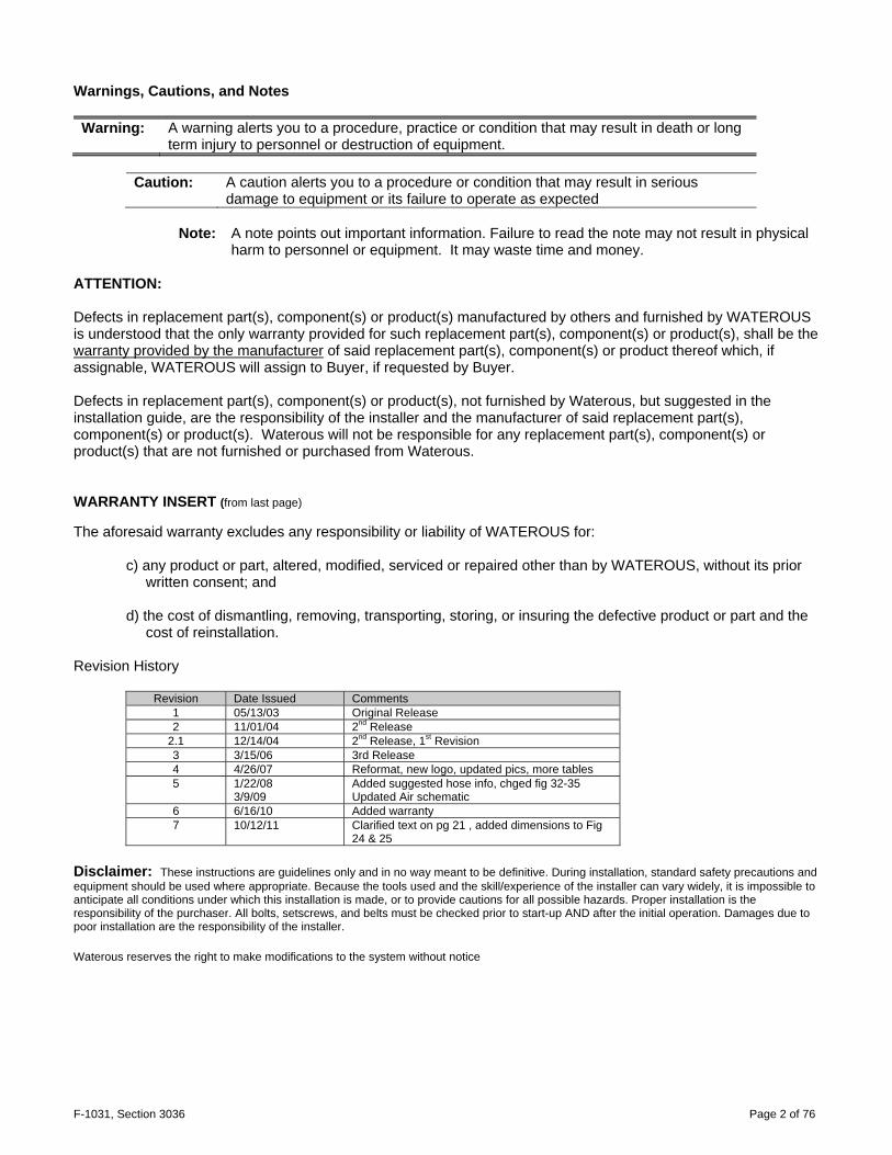
The illustrations shown in this manual may differ slightly from the parts that were shipped. The primary use of the compressor kits is to provide compressed air for Compressed Air Foam Systems (CAFS) in fire-fighting vehicles. Water to cool the compressor is supplied by the vehicle's pump, from its tank or an exterior source. If the kit is not installed in a fire-fighting vehicle, the compressor requires alternate cooling, such as an air-oil cooler.
The compressor kits do not include:
• (PTO) Transmission power take-off and drive shaft • Foam proportioner, foam tank, foam distribution manifold for CAFS • Air, water and hydraulic hoses and hose fittings • Air and water check valves • Air discharge valves • Air manifold • Master air pressure gauge
New installation tasks include:
• Installing the PTO (follow the manufacturer's instructions) • Installing the foam proportioner (follow the manufacturer's instructions) • Installing the compressor and connecting it to the PTO • Installing the rest of the hydraulic system (sump, filters and cooler) • Installing gauges, valves, and the Auto-Sync controls • Running water, air and hydraulic tubing for control systems, cooling, and compressed air delivery. • Filling and testing the hydraulic system • Calibrating the Auto-Sync system
Retrofitting into existing apparatus also includes:
• Modifying the water distribution system to install compressed air inputs, foam distribution manifold, check valves, the compressor cooling loop, and the balance valve.
• Installing additional discharges (optional)
F-1031, Section 3036 Page 5 of 76
SECTION 2. INSTALLING THE WATEROUS COMPONENTS
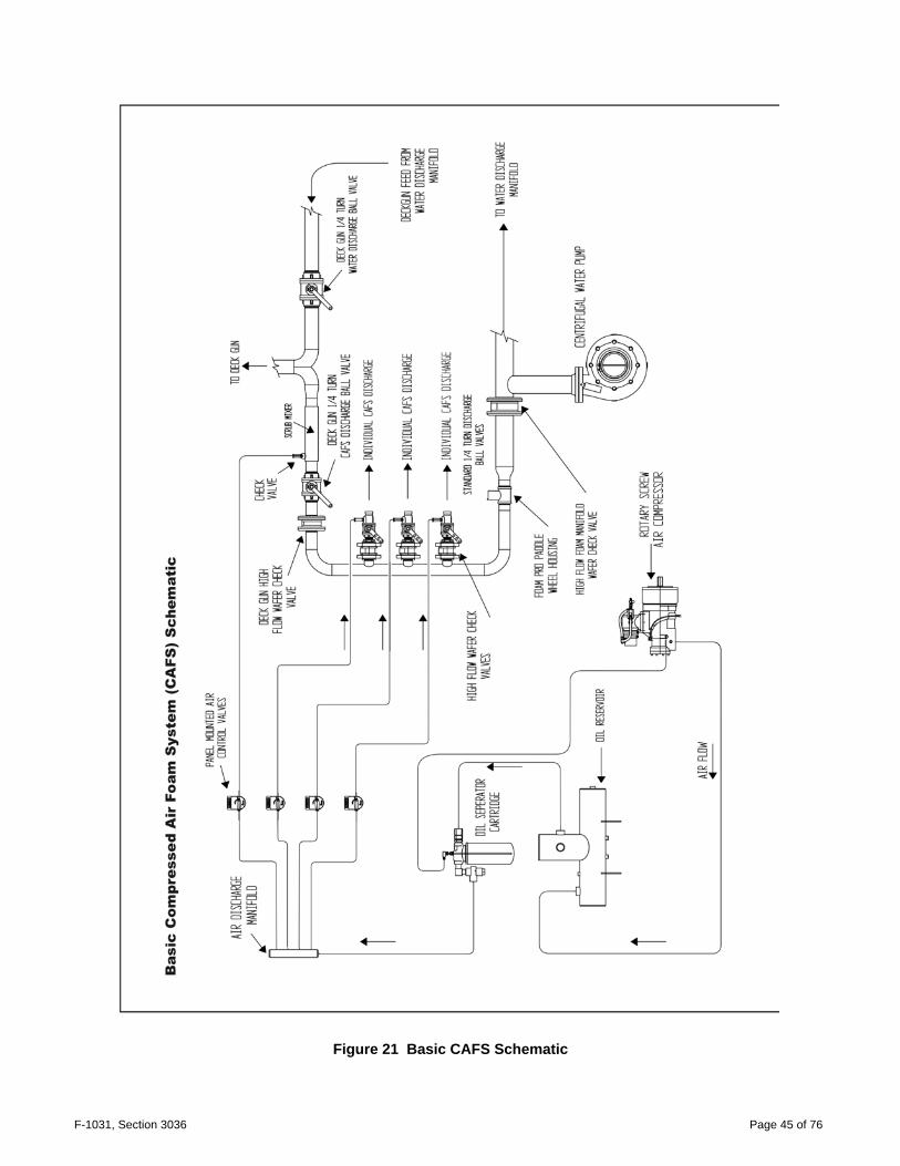
Refer to the Basic CAFS, Hydraulic, and Auto-Sync schematics in this manual to see how the Waterous components connect to the vehicle's foam and water distribution systems. Within the guidelines given here, components can be installed wherever there is room for them to be securely mounted. See the dimensional drawings in the rear.
Warning: Do not damage the vehicle chassis (also called frame or undercarriage) during installation.
Check with the vehicle manufacturer to make sure the planned welds and bolts are in acceptable areas.
• Components must be bolted to brackets welded to the pump compartment frame, or bolted directly
to the pump compartment frame. • Allow enough clearance for routine maintenance, including clearance for checking oil, adding oil,
adjusting pressure, changing filters, cleaning screens or opening drain valves. • The compressor must be horizontal, with its drive angle matched to the PTO. (see Figure 41) • The sump (oil/air reservoir) can be mounted at the same level as the compressor, or below it. If the
sump (oil level) must be mounted above the compressor (12 inches maximum) above the base of the air inlet, contact Waterous for the correct check valve to prevent compressor flooding. (Refer to Figure 5)
• The sump must be vertical, level, and in the proper orientation. Any extension to the sight glass
must be straight and level. • The oil sight glass must be visible after all the components are installed so oil level can be
monitored easily. • The heat exchanger (cooler) must be installed horizontally, with the drain at the lowest point. • To prevent damage to hydraulic and air lines, or accidentally disconnecting them, run them along
the support beams of the pump compartment whenever possible, bundled with cable ties or other fasteners.
• Wires, hoses, or tubing that passes through metal, such as a compartment panel, must have a
protective bushing or shield around the edge of the hole to protect against abrasion. • To make troubleshooting easier, use colored air hoses as supplied, and shown on the air
schematic. • Labeling the lines is strongly recommended.
F-1031, Section 3036 Page 6 of 76
A. PTO installation
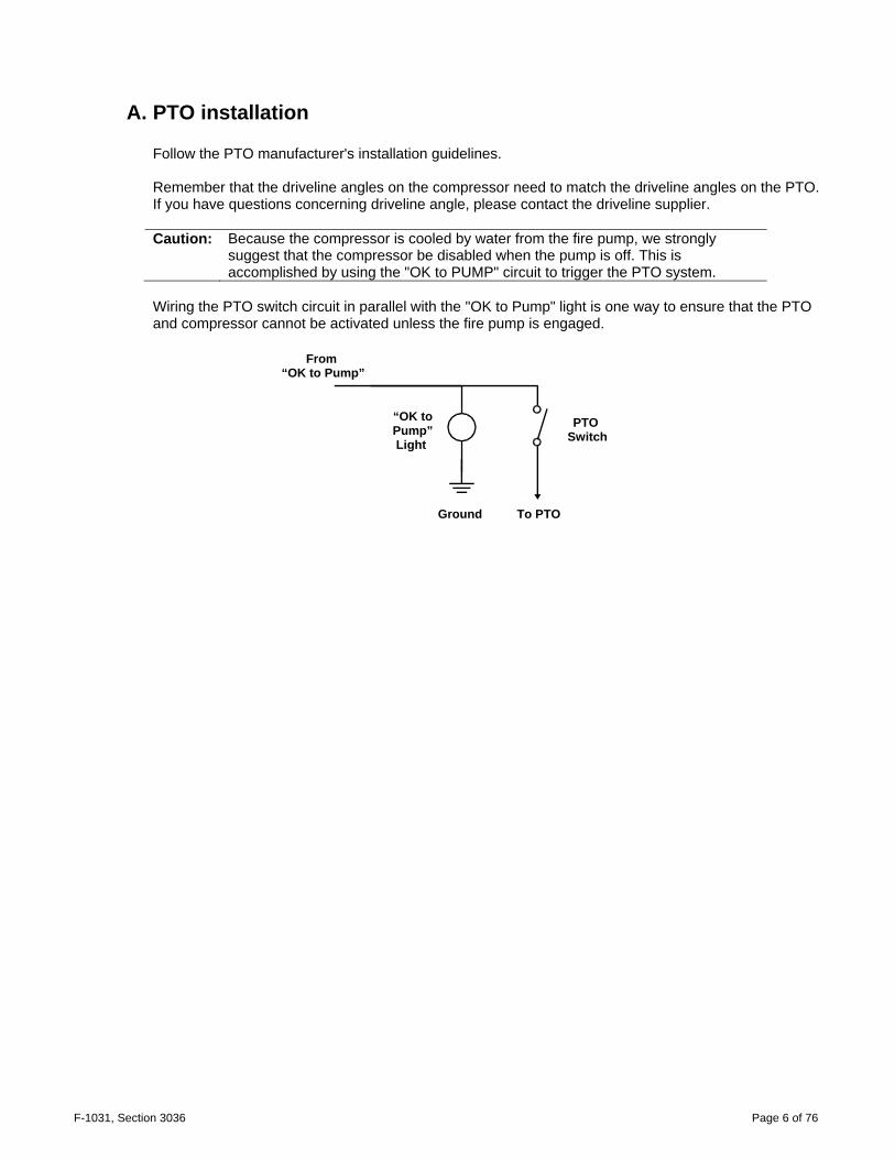
Follow the PTO manufacturer's installation guidelines. Remember that the driveline angles on the compressor need to match the driveline angles on the PTO. If you have questions concerning driveline angle, please contact the driveline supplier. Caution: Because the compressor is cooled by water from the fire pump, we strongly
suggest that the compressor be disabled when the pump is off. This is accomplished by using the "OK to PUMP" circuit to trigger the PTO system.
Wiring the PTO switch circuit in parallel with the "OK to Pump" light is one way to ensure that the PTO and compressor cannot be activated unless the fire pump is engaged.
From
“OK to Pump”
“OK to Pump” Light
PTO Switch
Ground To PTO

F-1031, Section 3036 Page 7 of 76
B. Air compressor installation
I. The Compressor
Compressor
with yoke, top view Compressor with flange
Compressor, rear view
Air Inlet
Fixed/ Manual Pressure Regulator
Air Inlet Trim Valve
Oil Inject from Cooler
F-1031, Section 3036 Page 8 of 76
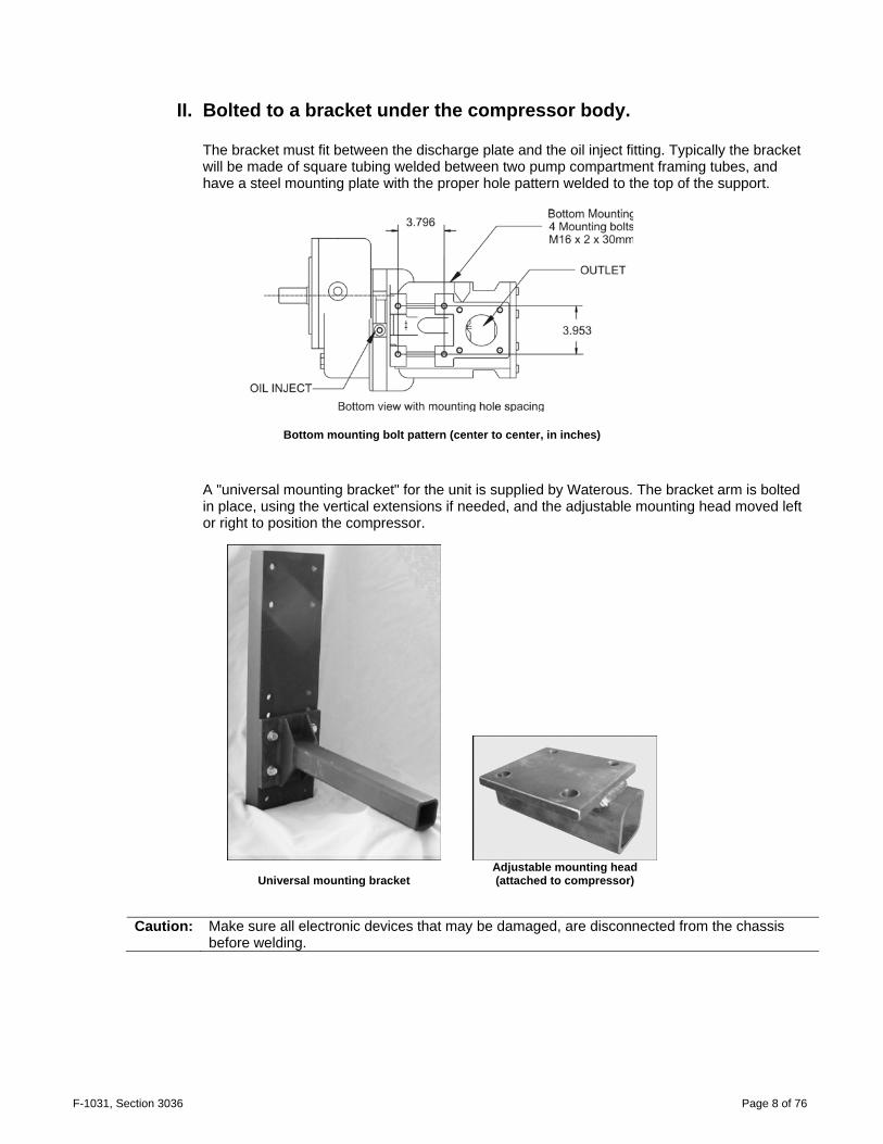
II. Bolted to a bracket under the compressor body.
The bracket must fit between the discharge plate and the oil inject fitting. Typically the bracket will be made of square tubing welded between two pump compartment framing tubes, and have a steel mounting plate with the proper hole pattern welded to the top of the support.
Bottom mounting bolt pattern (center to center, in inches)
A "universal mounting bracket" for the unit is supplied by Waterous. The bracket arm is bolted in place, using the vertical extensions if needed, and the adjustable mounting head moved left or right to position the compressor.
Universal mounting bracket Adjustable mounting head (attached to compressor)
Caution: Make sure all electronic devices that may be damaged, are disconnected from the chassis before welding.
F-1031, Section 3036 Page 9 of 76
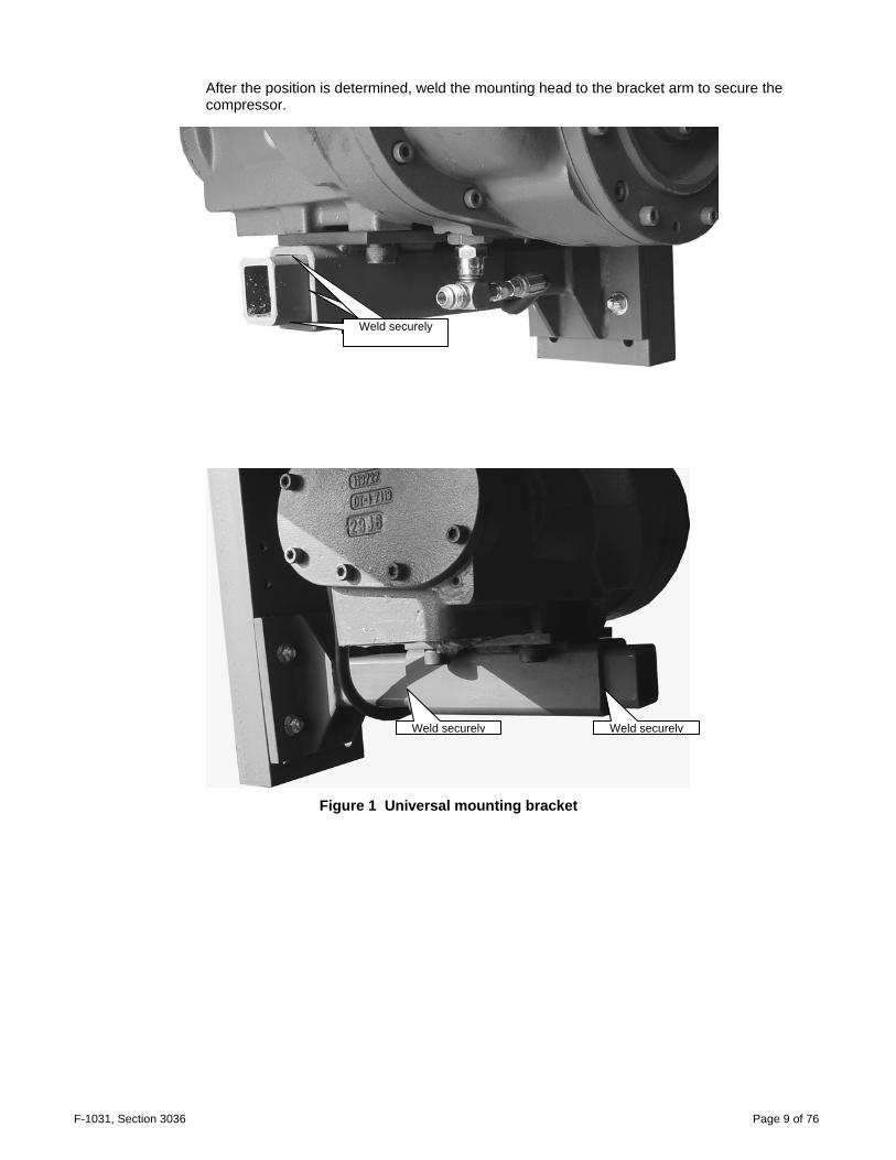
After the position is determined, weld the mounting head to the bracket arm to secure the compressor.
Figure 1 Universal mounting bracket
Weld securely
Weld securely
Weld securely
Weld securelyWeld securely

F-1031, Section 3036 Page 10 of 76
Compressor on the universal bracket in a typical installation.
The main drive shaft can be on either side of the truck, depending on where the PTO is located.
Compressor on custom made bracket in a non-typical installation. The vehicle had a PTO-driven pump on the left side of the drive shaft. Installation was difficult because the clearance for the drive shaft was tight. Compressor on an OEM manufactured bracket that suspends it under the pump cabinet. The main drive shaft is to the left of the compressor.
F-1031, Section 3036 Page 11 of 76
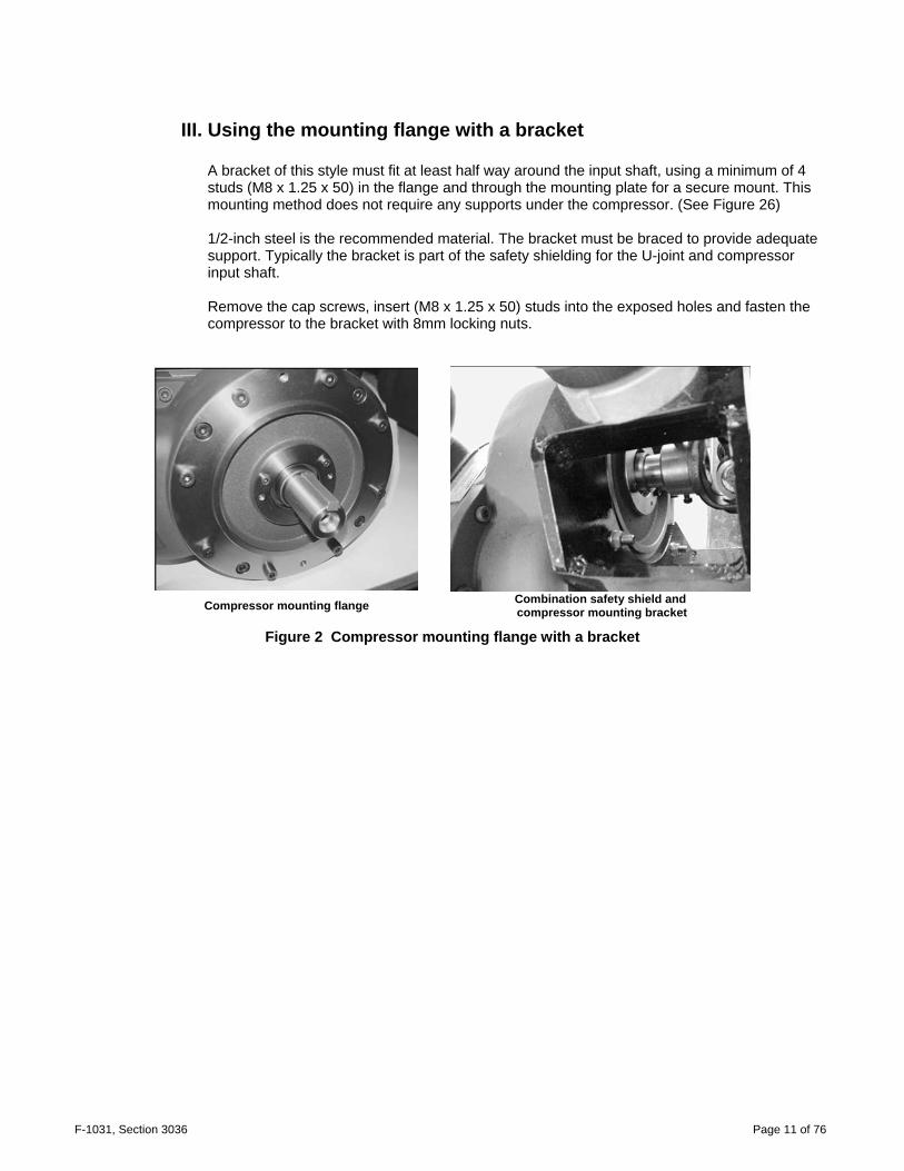
III. Using the mounting flange with a bracket
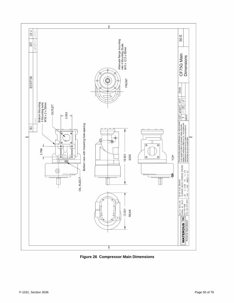
A bracket of this style must fit at least half way around the input shaft, using a minimum of 4 studs (M8 x 1.25 x 50) in the flange and through the mounting plate for a secure mount. This mounting method does not require any supports under the compressor. (See Figure 26) 1/2-inch steel is the recommended material. The bracket must be braced to provide adequate support. Typically the bracket is part of the safety shielding for the U-joint and compressor input shaft. Remove the cap screws, insert (M8 x 1.25 x 50) studs into the exposed holes and fasten the compressor to the bracket with 8mm locking nuts.
Compressor mounting flange
Combination safety shield and compressor mounting bracket
Figure 2 Compressor mounting flange with a bracket
F-1031, Section 3036 Page 12 of 76
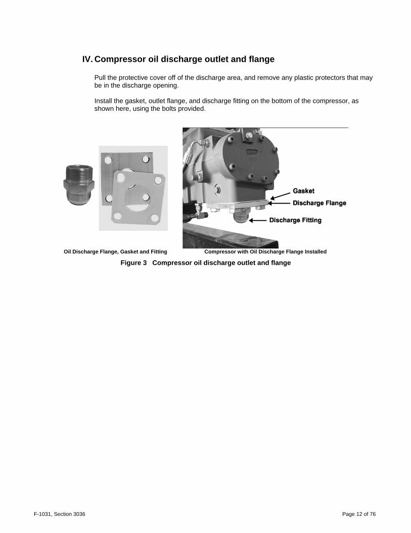
IV. Compressor oil discharge outlet and flange
Pull the protective cover off of the discharge area, and remove any plastic protectors that may be in the discharge opening. Install the gasket, outlet flange, and discharge fitting on the bottom of the compressor, as shown here, using the bolts provided.
Oil Discharge Flange, Gasket and Fitting Compressor with Oil Discharge Flange Installed
Figure 3 Compressor oil discharge outlet and flange

F-1031, Section 3036 Page 13 of 76
V. Connecting the Compressor to the PTO The compressor is shipped with a PTO companion flange (older units came with a yoke) attached to the input shaft by the two set screws. The yoke had to be removed and sent to the drive line manufacturer when the shaft was ordered. Install the drive line according to the manufacturer's instructions. (See Figure 41 for angle limits and/or SECTION 7 “Basic Driveline Installation Suggestions” in the back of the manual.
Typical compressor with input shaft connected by yoke.
Compressor input shaft with
Companion Flange Typical compressor with input shaft connected
by companion flange.
Close up of flange attached to drive line

F-1031, Section 3036 Page 14 of 76
Figure 4 Companion Flange Adapter or equivalent.
(Dana Spicer (C-22329) or equivalent. Not supplied by Waterous)
C. Air Inlet and Filter
The air inlet on the air compressor can be turned in 90° increments because the bolt pattern is symmetrical. This simplifies installation of the air filter. If you turn the inlet, you will need longer tubing. Either acquire colored tubing locally or contact Waterous for the correct lengths and colors. To change the rotation of the air inlet, disconnect the tubing, unbolt the inlet, rotate the inlet, and install new tubing. Mount the air filter, considering the following factors:
• Air intake area must be unobstructed. • Air intake tubing should be as short and straight as possible. • Maintenance clearance must be adequate for removing and replacing the filter. • The filter should be in an area that is unlikely to get wet.
The air inlet tubing (included) from the filter to the air inlet is usually made of thin-wall metal tubing and rubber elbows. Plumb it as though it were an engine air inlet. Do not use flexible exhaust tubing or any material that water or dirt can easily penetrate.

F-1031, Section 3036 Page 15 of 76
D. Air-oil reservoir (sump) installation Note: Waterous will not be responsible for systems where the sump and sight glass are installed such
that the oil level cannot be checked or does not display the correct oil level due to improper installation.
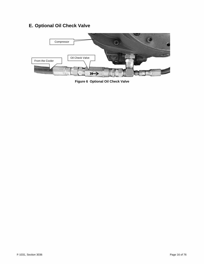
The sump works best when it is installed so that the sight glass opening (oil level) is below the base of the air intake of the air compressor (Figure 5A), although mounting the sump at the same level as the compressor is acceptable. In some cases, finding room for the sump can be difficult. It is acceptable to mount the oil sump (reference the oil level) up to 12 inches higher than the air compressor air inlet (Figure 5B). However, over 12 inches will require the installation of a check valve (Figure 6) to prevent oil from flooding the compressor. The check valve may be ordered from Waterous when ordering the system. The unit has two sump styles, the usual vertical sump and the optional "T-shaped" sump.
A
B
Figure 5 Sump height to Compressor
Oil Check Valve
F-1031, Section 3036 Page 16 of 76
E. Optional Oil Check Valve
Figure 6 Optional Oil Check Valve
From the Cooler Oil Check Valve
Compressor
F-1031, Section 3036 Page 17 of 76
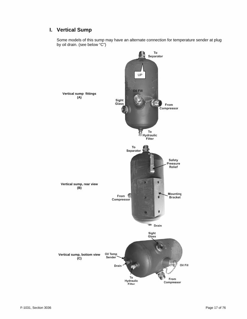
I. Vertical Sump
Some models of this sump may have an alternate connection for temperature sender at plug by oil drain. (see below “C”)
Vertical sump fittings (A)
Vertical sump, rear view (B)
Vertical sump, bottom view (C)
UP
F-1031, Section 3036 Page 18 of 76
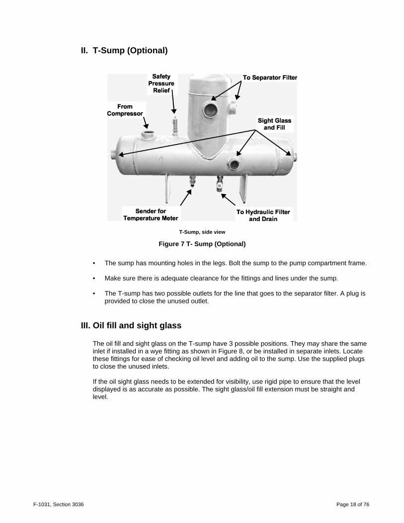
II. T-Sump (Optional)
T-Sump, side view
Figure 7 T- Sump (Optional)
• The sump has mounting holes in the legs. Bolt the sump to the pump compartment frame. • Make sure there is adequate clearance for the fittings and lines under the sump. • The T-sump has two possible outlets for the line that goes to the separator filter. A plug is
provided to close the unused outlet.
III. Oil fill and sight glass
The oil fill and sight glass on the T-sump have 3 possible positions. They may share the same inlet if installed in a wye fitting as shown in Figure 8, or be installed in separate inlets. Locate these fittings for ease of checking oil level and adding oil to the sump. Use the supplied plugs to close the unused inlets. If the oil sight glass needs to be extended for visibility, use rigid pipe to ensure that the level displayed is as accurate as possible. The sight glass/oil fill extension must be straight and level.

F-1031, Section 3036 Page 19 of 76
Oil fill and sight glass in a Wye fitting Ideal installation, with sight glass and oil fill easy to access
90° Elbow on a sight glass for better visibility Two elbows on an oil fill cap for accessibility.
Figure 8 Sight Gauge
IV. T-Sump Drain
The drain and the output to the hydraulic filter may share an outlet port.
To Hydraulic Filter

F-1031, Section 3036 Page 20 of 76
F. Oil Temperature Gauge (all sumps)
Mount the gauge on the pump operator's control panel where it will be easy to monitor. • The gauge connects to the larger of the two prongs on the sender. • The smaller prong, which is labeled "WK", may be used to
activate an oil temperature warning light or alarm (not provided). Waterous recommends installing an over-temperature device. This prong is one side of a temperature sensitive switch that will close at 250°F. The other side is grounded through the metal of the sump. The prong can be connected to the negative side of an audible alarm or warning light.
• Follow the installation instructions in the temperature gauge box
to connect the sender to the gauge and the warning light.
Figure 9 Temperature sender, on Sump
F-1031, Section 3036 Page 21 of 76
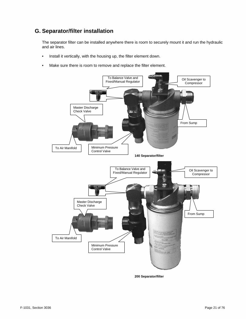
G. Separator/filter installation
The separator filter can be installed anywhere there is room to securely mount it and run the hydraulic and air lines. • Install it vertically, with the housing up, the filter element down. • Make sure there is room to remove and replace the filter element.
140 Separator/filter
200 Separator/filter
To Balance Valve and Fixed/Manual Regulator
Oil Scavenger to Compressor
From Sump
Oil Scavenger to Compressor
From Sump
To Balance Valve and Fixed/Manual Regulator
Master Discharge Check Valve
To Air Manifold
Master Discharge Check Valve
To Air Manifold Minimum Pressure Control Valve
Minimum Pressure Control Valve
F-1031, Section 3036 Page 22 of 76
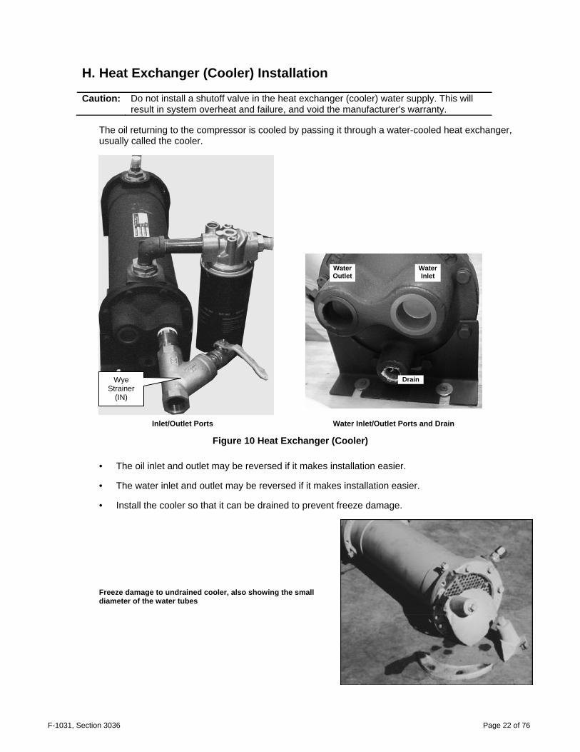
H. Heat Exchanger (Cooler) Installation
Caution: Do not install a shutoff valve in the heat exchanger (cooler) water supply. This will result in system overheat and failure, and void the manufacturer's warranty.
The oil returning to the compressor is cooled by passing it through a water-cooled heat exchanger, usually called the cooler.
Inlet/Outlet Ports Water Inlet/Outlet Ports and Drain
Figure 10 Heat Exchanger (Cooler)
• The oil inlet and outlet may be reversed if it makes installation easier. • The water inlet and outlet may be reversed if it makes installation easier. • Install the cooler so that it can be drained to prevent freeze damage.
Freeze damage to undrained cooler, also showing the small diameter of the water tubes
WaterOutlet
Water Inlet
Drain Wye Strainer
(IN)
F-1031, Section 3036 Page 23 of 76
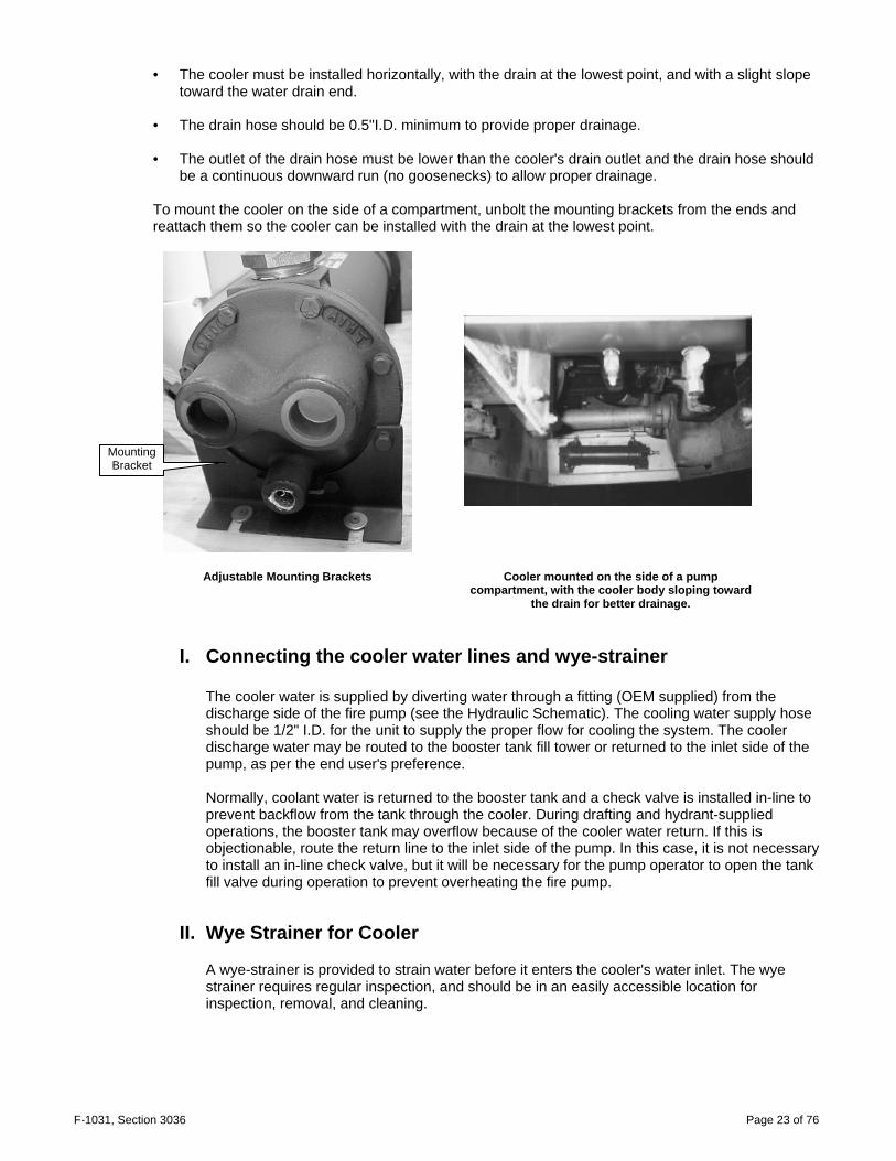
• The cooler must be installed horizontally, with the drain at the lowest point, and with a slight slope toward the water drain end.
• The drain hose should be 0.5"I.D. minimum to provide proper drainage. • The outlet of the drain hose must be lower than the cooler's drain outlet and the drain hose should
be a continuous downward run (no goosenecks) to allow proper drainage.
To mount the cooler on the side of a compartment, unbolt the mounting brackets from the ends and reattach them so the cooler can be installed with the drain at the lowest point.
Adjustable Mounting Brackets Cooler mounted on the side of a pump compartment, with the cooler body sloping toward
the drain for better drainage.
I. Connecting the cooler water lines and wye-strainer The cooler water is supplied by diverting water through a fitting (OEM supplied) from the discharge side of the fire pump (see the Hydraulic Schematic). The cooling water supply hose should be 1/2" I.D. for the unit to supply the proper flow for cooling the system. The cooler discharge water may be routed to the booster tank fill tower or returned to the inlet side of the pump, as per the end user's preference. Normally, coolant water is returned to the booster tank and a check valve is installed in-line to prevent backflow from the tank through the cooler. During drafting and hydrant-supplied operations, the booster tank may overflow because of the cooler water return. If this is objectionable, route the return line to the inlet side of the pump. In this case, it is not necessary to install an in-line check valve, but it will be necessary for the pump operator to open the tank fill valve during operation to prevent overheating the fire pump.
II. Wye Strainer for Cooler
A wye-strainer is provided to strain water before it enters the cooler's water inlet. The wye strainer requires regular inspection, and should be in an easily accessible location for inspection, removal, and cleaning.
Mounting Bracket

F-1031, Section 3036 Page 24 of 76
Caution: Waterous is not responsible for damage due to plugged strainers. If the customer's
water system contains excessive debris, or the vehicle relies on drafting for its water supply, it may be necessary to install a larger strainer and/or a clean-out valve on the wye-strainer. Without good water flow through the heat exchanger (cooler), the compressor will overheat. Compressor performance will be inadequate, and it may fail completely. Omitting the Wye-strainer or removing the screen from the Wye does not improve water flow. It will allow debris into the cooler, which can clog the tiny heat exchanger (cooler) tubes and restrict water flow.
Figure 11 Wye Strainer Figure 12 Wye-strainer installed, with cleanout valve.
Figure 13 Clean Strainer Figure 14 Dirty Strainer

F-1031, Section 3036 Page 25 of 76
I. Hydraulic Filter Installation
Caution: This is a one-way filter. Oil must flow in the direction indicated by the arrows on the top of the filter.
Cooler Assembly with Hydraulic Filter
The hydraulic filter assembly comes installed on the Cooler assembly. Remote mounting brackets are available from Waterous. • Install with the housing up, the filter element down. • Make sure there is enough room so the filter can be removed and replaced. • Make sure the direction of oil flow is correct. NOTE: Waterous has phased out in-line thermostats from the hydraulic circuit.
Output
Intput
Hydraulic Oil Filter
Assembly
Hydraulic Oil Filter
Assembly

F-1031, Section 3036 Page 26 of 76
J. Auto-Sync Control System Installation
The Auto-Sync control system will have electric or manual control valves (depending on when the system was manufactured). See Figure 39 or Figure 40 for the Manual schematics, and Figure 37 or Figure 38 for the Electrical schematic. Figure 42 for either panel cutout.
I. Manual valves
Manual Auto Sync valve assembly
Manual Auto Sync Control Switches and Label Typical Air Pressure Gauge
Figure 15 Manual Auto-sync
Install the control switch assembly and the master air pressure gauge (not included) on the pump control panel.
1. Turn the control knobs to FIXED and RUN. 2. Loosen the setscrews and remove the knobs and nuts from the front of the assembly. 3. Remove the label plate. 4. Use the label as a template for making the holes for the control valves and the
mounting bolts, or use the dimensional drawing provided. 5. From the rear, insert the valve stems through the mounting holes. 6. Attach the label to the pump control panel.
7. Replace the nuts and knobs on the front of the assembly, making sure to align the
knob indicators to FIXED and RUN. Make sure the knobs do not bottom out on the valve bodies. This will prevent the system from working properly.
8. Tighten the setscrews.

F-1031, Section 3036 Page 27 of 76
II. Electric Valves (Solenoids)
The electric valve assembly comes on a mounting bracket with the connecting wires and connector already installed.
Electrical Auto Sync Control Switch and Label Auto Sync valve assembly (electric)
Figure 16 Electric Auto-sync
1. Install the valves in a convenient location, close enough to the pump operators control panel to run the control wires. Extension cables are available from Waterous, if needed.
2. Install the valve control switch and label on the pump operator's control panel. 3. Run the control wire from the valves to the switch and plug the connectors together. 4. Connect the remaining wire to a +12V supply. 5. Secure the control signal wire to the compartment frame. Note: If there is excess wire, do not coil it. Coils of wire act as antennas, either receiving or
radiating stray EMF signals and interfere with this or other equipment. Bundle the wire harness back on itself, and secure it in a bundle with the folded wires parallel to each other.

F-1031, Section 3036 Page 28 of 76
K. Balance Valve Installation
1. Install the Piloted Balance Valve (PBV) so it is accessible for adjusting.
2. Ensure that the water connection is from the discharge side of the pump, and that the valve is correctly oriented, with the water entering the bottom of the valve. Note: Waterous will not accept responsibility for the performance of any systems with an
inaccessible PBV.
3. Connect the separator filter output to the balance valve.
Piloted Balance Valve inlets and outputs, with push-on hoses. Caution: DO NOT use oil or hose clamps on the Auto Sync system push-on hoses.
The push-on hose and fittings can be installed more easily if the hose ends are first soaked in hot water with a small amount of dish soap. Connect the Auto-Sync system air hoses as shown in the Auto-Sync Air Schematic, and connect the water line from the discharge side of the fire pump. Colored hoses are supplied with the compressor kit, long enough for an average installation, with push-on hose fittings. The schematic is also color coded, which simplifies the installation. Future service issues are easy to resolve as long as the colored hose is used as suggested and supplied.
Air in from Separator Filter and Air out to RUN/UNLOAD side of Auto Sync Control Manifold
Air out to FIXED/AUTO side ofAuto Sync Control Manifold
Water from discharge side of the Fire Pump
F-1031, Section 3036 Page 29 of 76
SECTION 3. INITIAL POWER-UP
A. Post-Installation, Pre-Power up Safety Check
Before you power-up the Waterous system: 1. Remove all tools, shop towels, hose trimmings and other debris from the compartments. 2. Double-check all hydraulic, air and water lines against the schematics, testing to make sure each
connection is tight and that the hose is fully inserted into the fitting. 3. Check all of the unused inlets: plastic shipping caps must be removed and replaced with the
appropriate plug or cap. 4. Make sure all drain valves are closed. 5. Make sure the gauges are connected to the appropriate sender (temperature, pressure, etc.) 6. Fill the sump with the specified hydraulic oil until the oil level is 1/2 way up the sight glass. You will
need to add more oil later, to compensate for oil that remains in the hydraulic lines and the compressor. Oil used in the system is ISO 68wt hydraulic oil. It must be "Low-foaming" or "Anti-foam".
7. Make sure the foam proportioner is operating properly. (see the manufacturer's installation guide). 8. Make sure the fire pump is operating properly and that water flows through the oil cooler. 9. Make sure the connection between the compressor drive shaft and the PTO is secure and that the
driveline angles match.
F-1031, Section 3036 Page 30 of 76
B. Initial Compressor System Power-up Warnings: Compressed air can be dangerous. Make sure the pressure is allowed to bleed down to
atmospheric pressure before opening any connections or valves. Check ALL fluids for the engine before initial power up.
1. Remove the air filter plumbing and pour 8 to 16 ounces of hydraulic oil into the air inlet of the compressor.
2. Replace the air filter plumbing. 3. Place the Auto-Sync system in UNLOAD and AUTO (UNLOAD for electric Auto-Sync) 4. Start the vehicle's engine and engage the PTO. 5. With the system powered up, turn the Auto-Sync to the RUN/FIXED positions (FIXED for electric
Auto-Sync). Air pressure should rise to about 110 PSI. 6. Check for leaks by listening for hissing noises at the fittings. 7. Shut the PTO off, allow the pressure to bleed off, and then add oil to the sump to bring the oil level
1/2 way up the sight glass. 8. Proceed to "Initial Adjustment Of The Auto-Sync Air Balancing System".

F-1031, Section 3036 Page 31 of 76
SECTION 4. INITIAL ADJUSTMENT OF THE AUTO-SYNC AIR BALANCING SYSTEM
CAFS retrofit kits and any other system shipped as separate components will need calibrating after installation.
This seldom needs adjusting after the initial setup if the rest of the system is well maintained. Note: Do not adjust the Auto Sync components to compensate for problems elsewhere in the CAFS
system. Before you make any adjustments, make sure the oil level in the sump is correct, the air and oil filters are not overdue for servicing, the oil is not overdue for changing, the compressor is not overheating, the oil cooler strainer is clean, and the air lines do not have leaks. Always start by adjusting UNLOAD mode, then FIXED, then AUTO.
A common problem is unauthorized adjustment of the balance valve in an attempt to improve performance. If unauthorized adjustments to the Auto Sync are a problem we suggest placing a seal over the adjustment points. This will let maintenance personnel know if the system has been tampered with.
A. Electric Auto-Sync Initial Setup
Colored hoses and fittings are supplied with the compressor kit for the average installation. The schematic is color coded to simplify installation. This also makes future service issues easier to resolve, provided suggested hose colors are used. CAFS retrofit kits and any other system shipped as separate components will need calibrating after installation.
NOTE: Before you make any adjustments, make sure the oil level in the sump is correct, and the air
lines do not have leaks or obstructions. Do not adjust the Auto-Sync components to compensate for problems elsewhere in the CAF system.
Always start by adjusting UNLOAD mode, then FIXED, then AUTO.
I. UNLOAD Mode Initial Setting
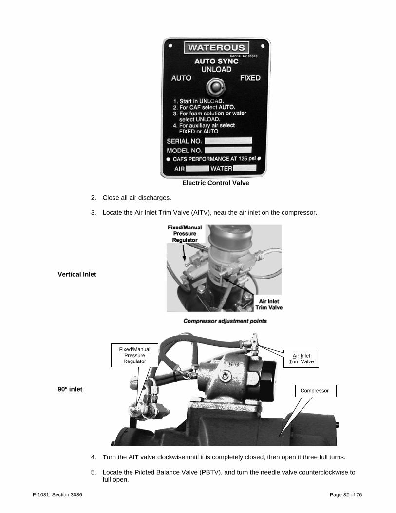
1. Before the system is powered up, set the controls on the Auto-Sync control panel to UNLOAD.
F-1031, Section 3036 Page 32 of 76
Electric Control Valve
2. Close all air discharges. 3. Locate the Air Inlet Trim Valve (AITV), near the air inlet on the compressor.
Vertical Inlet
90º inlet
4. Turn the AIT valve clockwise until it is completely closed, then open it three full turns. 5. Locate the Piloted Balance Valve (PBTV), and turn the needle valve counterclockwise to
full open.
Air Inlet Trim Valve
Compressor
Fixed/Manual Pressure Regulator

F-1031, Section 3036 Page 33 of 76
Piloted Balance Trim Valve (PBTV)
6. Start the fire pump, and with the engine at idle, establish water flow through a discharge or
tank re-circulation. 7. Engage the PTO.
CAUTION: Do not engage the PTO above 1000 engine RPM
8. With 140-200-P systems, the main pressure gauge should read approximately 40 PSI with
all discharges closed. Some systems may read lower. This is acceptable.
II. FIXED Mode Initial Setting
The FIXED pressure for a newly installed PTO retrofit kit is about 110 PSI. It must be adjusted to 150 PSI.
1. Locate the Fixed/Manual Pressure Regulator on the compressor and loosen the lock nut
on the adjustment screw. 2. Place the controls on the Auto-Sync control panel to FIXED. Wait until the compressor
pressure stabilizes.
3. The target operating pressure is 145-150 PSI. Monitor the air pressure reading as you adjust the regulator screw. Give the system several seconds to stabilize between adjustments, and make partial turns of the screw to avoid overshooting the target pressure.
• Turning the screw IN (CW) will increase pressure.
• Turning the screw OUT (CCW) will decrease pressure.
4. After the desired fixed pressure is achieved, tighten the lock nut. 5. Verify that the fixed regulator is performing properly by varying the engine speed as you
watch the air pressure gauge. The pressure should remain steady at the setting you made. Repeat steps 2 through 4 if needed.
6. Turn the controls to UNLOAD and back to FIXED. The air pressure should rise to the fixed
pressure. It may overshoot and drop back to the target pressure, but that is normal. 7. After the FIXED mode is adjusted, proceed to AUTO mode adjustment.
Piloted Balance Trim Valve
F-1031, Section 3036 Page 34 of 76
III. AUTO Mode Initial Setting
The pressure for the FIXED mode must have been correctly set before you attempt to adjust the AUTO mode.
1. Make sure the fire pump is operating at 100 PSI at the main discharge, with minimal flow.
2. Place the controls on the Auto-Sync control panel to AUTO.
3. Read the main air pressure and water discharge pressure gauges.
4. The air pressure reading should be equal or up to 5% higher than the water pressure. If the
readings are in this range, go to step 7 and verify the operation at other pressures. 5. If the air pressure is not within +5% of the water pressure, adjust it as follows:
• If the air pressure is too high, turn the AITV clockwise in 1/2 turn increments to close it,
checking air and water pressure after each 1/2 turn. • If the air pressure is too low, turn the AITV counterclockwise 1/2 turn to open it and
check pressures.
• If the air pressure is still too low, open the valve another 1/2 turn and check the pressures again.
• Do not open the Air Inlet Trim Valve more than this. Use the PBTV if the pressure
remains too low.
6. If the air pressure remains too low, close the needle valve on the Piloted Balance Trim Valve (PBTV) one full turn clockwise and check the pressure gauges.
Repeat closing the PBTV one full turn until the air pressure is equal to or up to 5% higher than the water pressure. If the air pressure is too high after a full-turn of the PBTV, turn the Air Inlet Trim Valve clockwise to lower the pressure until the air pressure is equal to or up to 5% higher than the water pressure.
7. Verify the Auto-Sync system settings by varying the fire pump discharge pressure and
monitoring the water and air pressure gauges. The air pressure should rise and fall with the water pressure, matching it within 5%. Pressures should match at static pressure only. It is normal for the pressures to be unmatched when flowing water, air, or solution.
F-1031, Section 3036 Page 35 of 76
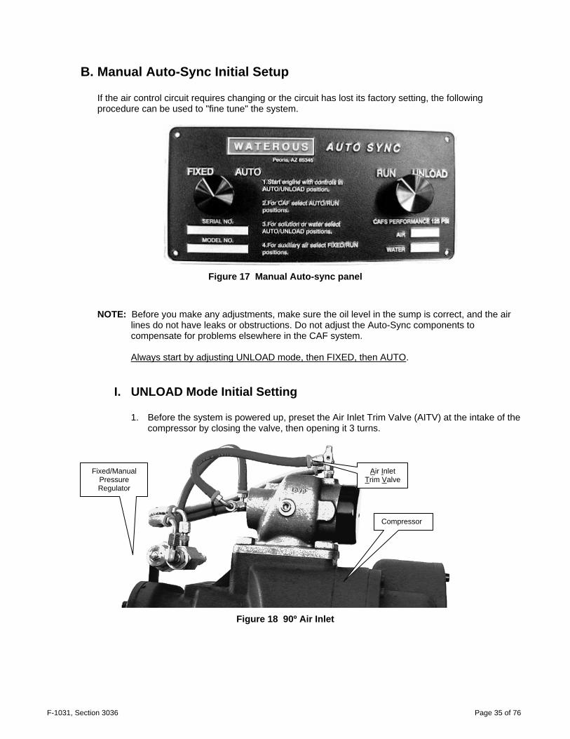
B. Manual Auto-Sync Initial Setup If the air control circuit requires changing or the circuit has lost its factory setting, the following procedure can be used to "fine tune" the system.
Figure 17 Manual Auto-sync panel
NOTE: Before you make any adjustments, make sure the oil level in the sump is correct, and the air lines do not have leaks or obstructions. Do not adjust the Auto-Sync components to compensate for problems elsewhere in the CAF system. Always start by adjusting UNLOAD mode, then FIXED, then AUTO.
I. UNLOAD Mode Initial Setting
1. Before the system is powered up, preset the Air Inlet Trim Valve (AITV) at the intake of the compressor by closing the valve, then opening it 3 turns.
Figure 18 90º Air Inlet
Air Inlet Trim Valve
Compressor
Fixed/Manual Pressure Regulator

F-1031, Section 3036 Page 36 of 76
2. Preset the Piloted Balance Trim Valve (PBTV) to full open.
Piloted Balance Trim Valve (PBTV)
3. Start the fire pump and, at idle, establish water flow either through a discharge or tank re-
circulation. 4. The Auto-Sync Control Panel should be in the FIXED/UNLOAD mode and all air
discharges closed. 5. Start the air compressor by placing the compressor engage switch to "ON."
Figure 19 Vertical Air Inlet
6. The main air pressure gauge should read 40-50 PSI. In the UNLOAD mode, this minimum
pressure is always present to provide compressor oil circulation.
We are ready to proceed with final adjustments for the FIXED and AUTO modes.
II. FIXED Air Initial Setting:
1. To set the pressure for the FIXED operation, first locate the "Fixed Pressure Regulator." The regulator has an adjustment screw with lock nut.
2. Loosen the regulator's lock nut. 3. Go to the Auto-Sync Panel and place controls to the FIXED/RUN positions. The
compressor will build pressure to some value and hold (regulate). 4. While monitoring the air pressure gauge, adjust the screw on the Fixed Pressure Regulator
until the desired pressure is reached. Turning the screw IN will INCREASE pressure and turning the screw OUT will DECREASE pressure.
5. Once the desired regulated pressure is achieved, tighten down the lock nut.
Piloted Balance Trim Valve

F-1031, Section 3036 Page 37 of 76
6. Verify the fixed regulator is performing by varying the compressor speed and monitoring
the air pressure gauge. The pressure should remain steady at your fixed pressure setting.
With the final adjustments to the FIXED air mode complete, proceed with setting the AUTO air mode.
III. AUTO Air Initial Setting:
1. With the fire pump operating at 100 PSI main discharge and minimum flow, place the Auto-Sync controls to the AUTO/RUN position.
2. Monitor main water discharge pressure gauge and the air pressure gauge. The pressure
readings should be the same. If not, proceed to step 3. 3. The Air Inlet Trim Valve (AITV) is the first valve to adjust.
a. If the air pressure is too high, close the trim valve in half turn increments, monitoring both water and air pressure gauges, until the pressures match. Once the pressures match, no further adjustments are needed, proceed to step 5.
b. If the air pressure is too low, open the trim valve a half turn, then check water and air
pressure gauges. c. If the air pressure is still too low, open the trim valve another half turn. If air pressures
match, no further adjustments are needed, proceed to step 5. d. If air pressure is still too low, proceed to step 4.
4. The Air Inlet Trim Valve (AITV) is now four turns open from fully closed. It is not desirable to
have the trim valve open more than four turns. In order to extend its range, go to the Piloted Balance Trim Valve (PBTV).
a. From the fully open position, close the PBTV one turn then check water and air
pressure gauges. b. If air is still too low, close the PBTV one additional turn and check gauges. c. Keep repeating this process until air pressure matches or is slightly higher than water
pressure. d. The final adjustment can be done using the AITV and step 4.
5. Verify the piloted balance valve is performing by varying the fire pump discharge pressure
and monitoring the water and air pressure gauges. The air pressure should follow the water pressure and match it. If not, repeat the final adjustment procedure.
6. If the air pressure remains too low, close the needle valve on the Piloted Balance Trim
Valve (PBTV) one full turn clockwise and check the pressure gauges. 7. Repeat closing the PBTV one full turn until the air pressure is equal to or up to 5% higher
than the water pressure.

F-1031, Section 3036 Page 38 of 76
8. If the air pressure is too high after a full-turn of the PBTV, turn the Air Inlet Trim Valve
clockwise to lower the pressure until the air pressure is equal to or up to 5% higher than the water pressure.
9. Verify the Auto-Sync system settings by varying the fire pump discharge pressure and
monitoring the water and air pressure gauges. The air pressure should rise and fall with the water pressure, matching it within 5%. Pressures should match at static pressure only. It is normal for the pressures to be unmatched when flowing water, air, or solution.

F-1031, Section 3036 Page 39 of 76
SECTION 5. SUGGESTED THIRD-PARTY COMPONENTS
Note: These are guidelines useful for many installations, but selection of third-party components is at the discretion of the system installer or vehicle manufacturer.
Defects in replacement part(s), component(s) or product(s) manufactured by others and furnished by WATEROUS is understood that the only warranty provided for such replacement part(s), component(s) or product(s), shall be the warranty provided by the manufacturer of said replacement part(s), component(s) or product thereof which, if assignable, WATEROUS will assign to Buyer, if requested by Buyer. Defects in replacement part(s), component(s) or product(s), not furnished by Waterous, but suggested in the installation guide, are the responsibility of the installer and the manufacturer of said replacement part(s), component(s) or product(s). Waterous will not be responsible for any replacement part(s), component(s) or product(s) that are not furnished or purchased from Waterous.
A. Suggested components for CAFS discharges:
The installer must provide fittings and tubing to connect the CAFS components to the vehicle's discharge outlets. These are suggested parts for the common discharge sizes. If the planned discharge system is not covered in this guideline, please contact Waterous. Note: Waterous strongly suggests that every CAFS discharge have an air check valve and a water
check valve, as shown below. The air check valve prevents foam solution from back flowing into the compressor and contaminating the oil. The water check valve isolates the discharge, preventing CAF from back flowing into the foam solution manifold and exiting through another discharge.
Figure 20 Typical CAFS Discharge
Discharge
Check Valve
Injection Point
Check Valves Valve body
Foam Solution
Compressed Air

F-1031, Section 3036 Page 40 of 76
B. Suggested Hose
The inside diameter (I.D.) of the hose is the most important factor, and any hose with the correct I.D. and rated to withstand the expected air system pressures (500 PSIG burst pressure) may be used. We have found the most cost-effective hose is the push-on type hose. H101 or H201 general-purpose hose has an acceptable working pressure. Gates, Dayco, Parker, Weatherhead and Aeroquip brands will suffice. All of these hoses come in a variety of colors for color-coding the lines by purpose.
Discharge: Suggested:
1” booster reel or 1” remote
Use 3/8” ID air hose.
1.5” and 2” Use 1/2” ID air hose 2-1/2” Use 3/4” ID air hose Auxiliary Air Outlet Use 3/8” ID air hose
Air brake tubing may also be used provided strict attention is paid to the inside diameters:
Size Working PSI Burst PSI
.375" OD is .250" ID 150 1400
.500" OD is .375" ID 150 950
.625" OD is .500" ID 150 900
.750" OD is .625" ID 150 800
Discharge fittings and Kits: Lists are available on request for various discharges.
For the hydraulic portion of the compressor system, it is necessary to use SAE 100R1 or SAE 100R5 as a minimum. Hose sizes necessary for installation are:
#4 for the scavenger from the separator filter to compressor. #8 for the oil inject and cooler circuit. #24 for the air out of the sump to the separator filter assembly.

F-1031, Section 3036 Page 41 of 76
C. Power Take-Off Suggestions
There are many PTO suppliers and many types of transmissions available, and the choice of PTO will in part depend on what can be installed in the vehicle. "Hot Shift" PTOs are commonly used. Make sure that there will be room to install the air compressor on a bracket close to the PTO, with their drive angles matched. Caution: The driveline angles MUST be matched to prevent serious damage to the
compressor, PTO, or transmission. Specific gear ratios vary among the different transmissions and PTO suppliers. The ratios suggested below are a guide for selecting the PTO. With these ratios, the rated CFM is usually achieved with the engine speed near 1400 RPM. Caution: A higher speed on the PTO means the CAFS system will reach the desired CFM
at lower engine speeds. Exceeding the compressor's rated RPM can damage the compressor, and void the warranty. In such applications, an over speed cut-out should be installed on the PTO to protect the compressor.
To calculate the possible compressor RPM, use this equation: Engine RPM x gear ratio on PTO x 3.267 = compressor rotor RPM
I. Compressor
The compressor produces 200 CFM at approximately 7200 rotor RPM and 140 CFM at approximately 5000 rotor RPM. The maximum rotor speed is 9000 RPM. CFM required PTO speed HP average
120-140 123-129% HI 32-40 160-180 143% HI 45-50
200 160% HI 55-60

F-1031, Section 3036 Page 42 of 76
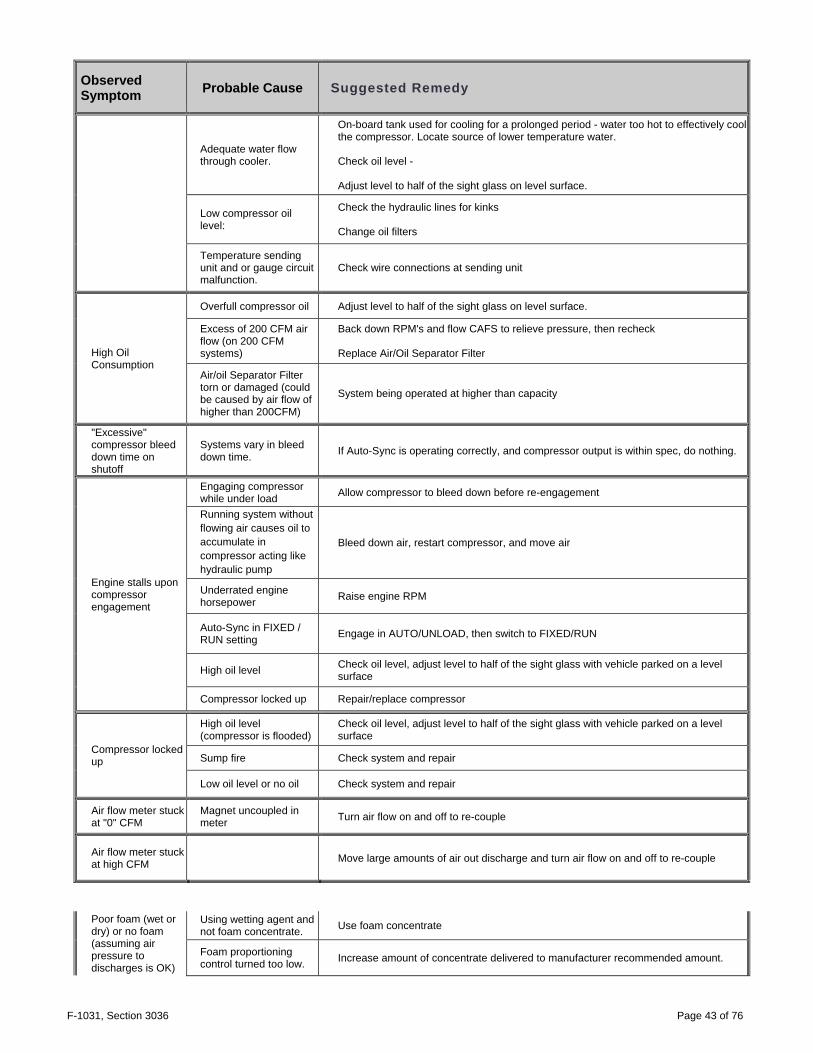
SECTION 6. TROUBLESHOOTING GUIDE
A. Troubleshooting - CAFS
Observed Symptom Probable Cause Suggested Remedy
Lack of air pressure from compressor
Lack of air supply to clutch (for air-clutch systems)
Repair air leak or re-establish air supply
Compressor not engaging No PTO engagement Confirm OK TO PUMP light is on, if not check wiring for damage or disconnected wire,
check PTO.
Compressor engaging. No air supply to discharges or insufficient air supply.
Auto-Sync switches not in correct position.
Confirm 40 PSI in UNLOAD position (200 CFM systems) and 50+ in run position. Smaller compressors have lower UNLOAD pressures. Verify when in FIXED/RUN whether pressure reflects 145-150 PSI
(electric valves) Verify there is power to the air solenoid and check operation of solenoid.
Air discharge solenoid not working. Repair/replace solenoid Air solenoid working - leak between solenoid and discharge. Repair leak.
Air check valve defective Replace or correct installation.
Trim valve out of adjustment Refer to trim valve instructions
Restricted minimum pressure valve Clean rust or debris from valve
Air plumbed before discharge valve seal Relocate to discharge side of discharge valve
Incorrect air line size Size according to discharge and replace line with correct size.
System functioning correctly, pressure gauge reading obviously incorrect.
Gauge malfunction, air line detached Check for air leaks, replace gauge
FIXED has pressure but AUTO has no pressure
No water supply to balance valve.
Check line for proper installation, with no kinks or obstructions. Refer to trim valve instructions.
Air discharge pressure too high
Red hose circuit (compressed air control) has leak or is disconnected.
Repair leak or attach hose
System overheating Inadequate water flow through cooler
Ensure adequate water flow through pump. Check Y strainer for obstruction, clean and reinstall Drain and flush cooler water tubes
F-1031, Section 3036 Page 43 of 76
Observed Symptom Probable Cause Suggested Remedy
Adequate water flow through cooler.
On-board tank used for cooling for a prolonged period - water too hot to effectively cool the compressor. Locate source of lower temperature water. Check oil level - Adjust level to half of the sight glass on level surface.
Low compressor oil level:
Check the hydraulic lines for kinks Change oil filters
Temperature sending unit and or gauge circuit malfunction.
Check wire connections at sending unit
High Oil Consumption
Overfull compressor oil Adjust level to half of the sight glass on level surface.
Excess of 200 CFM air flow (on 200 CFM systems)
Back down RPM's and flow CAFS to relieve pressure, then recheck Replace Air/Oil Separator Filter
Air/oil Separator Filter torn or damaged (could be caused by air flow of higher than 200CFM)
System being operated at higher than capacity
"Excessive" compressor bleed down time on shutoff
Systems vary in bleed down time. If Auto-Sync is operating correctly, and compressor output is within spec, do nothing.
Engine stalls upon compressor engagement
Engaging compressor while under load Allow compressor to bleed down before re-engagement
Running system without flowing air causes oil to accumulate in compressor acting like hydraulic pump
Bleed down air, restart compressor, and move air
Underrated engine horsepower Raise engine RPM
Auto-Sync in FIXED / RUN setting Engage in AUTO/UNLOAD, then switch to FIXED/RUN
High oil level Check oil level, adjust level to half of the sight glass with vehicle parked on a level surface
Compressor locked up Repair/replace compressor
Compressor locked up
High oil level (compressor is flooded)
Check oil level, adjust level to half of the sight glass with vehicle parked on a level surface
Sump fire Check system and repair
Low oil level or no oil Check system and repair
Air flow meter stuck at "0" CFM
Magnet uncoupled in meter Turn air flow on and off to re-couple
Air flow meter stuck at high CFM Move large amounts of air out discharge and turn air flow on and off to re-couple
Poor foam (wet or dry) or no foam (assuming air pressure to discharges is OK)
Using wetting agent and not foam concentrate. Use foam concentrate
Foam proportioning control turned too low. Increase amount of concentrate delivered to manufacturer recommended amount.
F-1031, Section 3036 Page 44 of 76
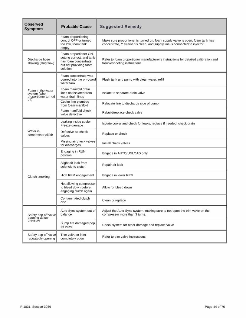
Observed Symptom Probable Cause Suggested Remedy
Foam proportioning control OFF or turned too low, foam tank empty.
Make sure proportioner is turned on, foam supply valve is open, foam tank has concentrate, Y strainer is clean, and supply line is connected to injector.
Discharge hose shaking (slug flow)
Foam proportioner ON, setting correct, and tank has foam concentrate, but not providing foam solution.
Refer to foam proportioner manufacturer's instructions for detailed calibration and troubleshooting instructions
Foam in the water system (when proportioner turned off)
Foam concentrate was poured into the on-board water tank
Flush tank and pump with clean water, refill
Foam manifold drain lines not isolated from water drain lines
Isolate to separate drain valve
Cooler line plumbed from foam manifold Relocate line to discharge side of pump
Foam manifold check valve defective Rebuild/replace check valve
Water in compressor oil/air
Leaking inside cooler Freeze damage Isolate cooler and check for leaks, replace if needed, check drain
Defective air check valves Replace or check
Missing air check valves for discharges Install check valves
Clutch smoking
Engaging in RUN position Engage in AUTO/UNLOAD only
Slight air leak from solenoid to clutch Repair air leak
High RPM engagement Engage in lower RPM
Not allowing compressor to bleed down before engaging clutch again
Allow for bleed down
Contaminated clutch disc Clean or replace
Safety pop off valve opening at low pressure
Auto-Sync system out of balance
Adjust the Auto-Sync system, making sure to not open the trim valve on the compressor more than 3 turns.
Sump fire damaged pop off valve Check system for other damage and replace valve
Safety pop off valve repeatedly opening
Trim valve or inlet completely open Refer to trim valve instructions
F-1031, Section 3036 Page 45 of 76
Figure 21 Basic CAFS Schematic
F-1031, Section 3036 Page 46 of 76
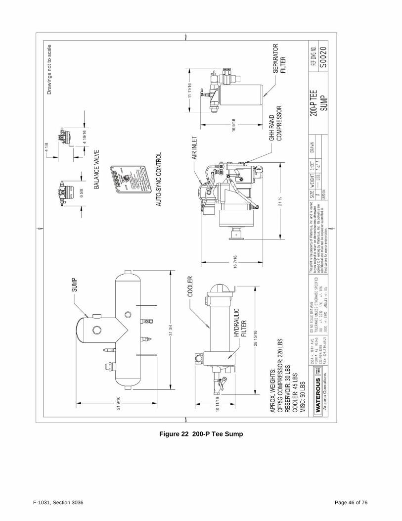
Figure 22 200-P Tee Sump

F-1031, Section 3036 Page 47 of 76
Figure 23 140-P Tee Sump

F-1031, Section 3036 Page 48 of 76
Figure 24 200-P Vertical Sump

F-1031, Section 3036 Page 49 of 76
Figure 25 140-P Vertical Sump
F-1031, Section 3036 Page 50 of 76
Figure 26 Compressor Main Dimensions
F-1031, Section 3036 Page 51 of 76
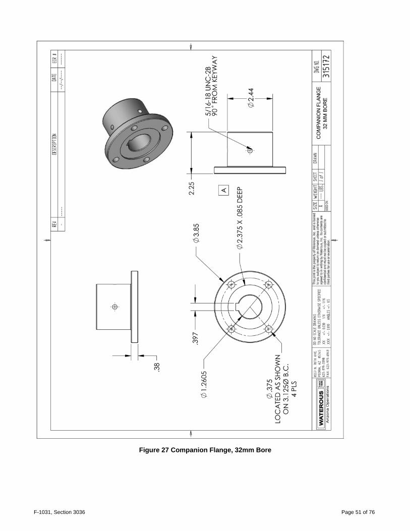
Figure 27 Companion Flange, 32mm Bore
F-1031, Section 3036 Page 52 of 76
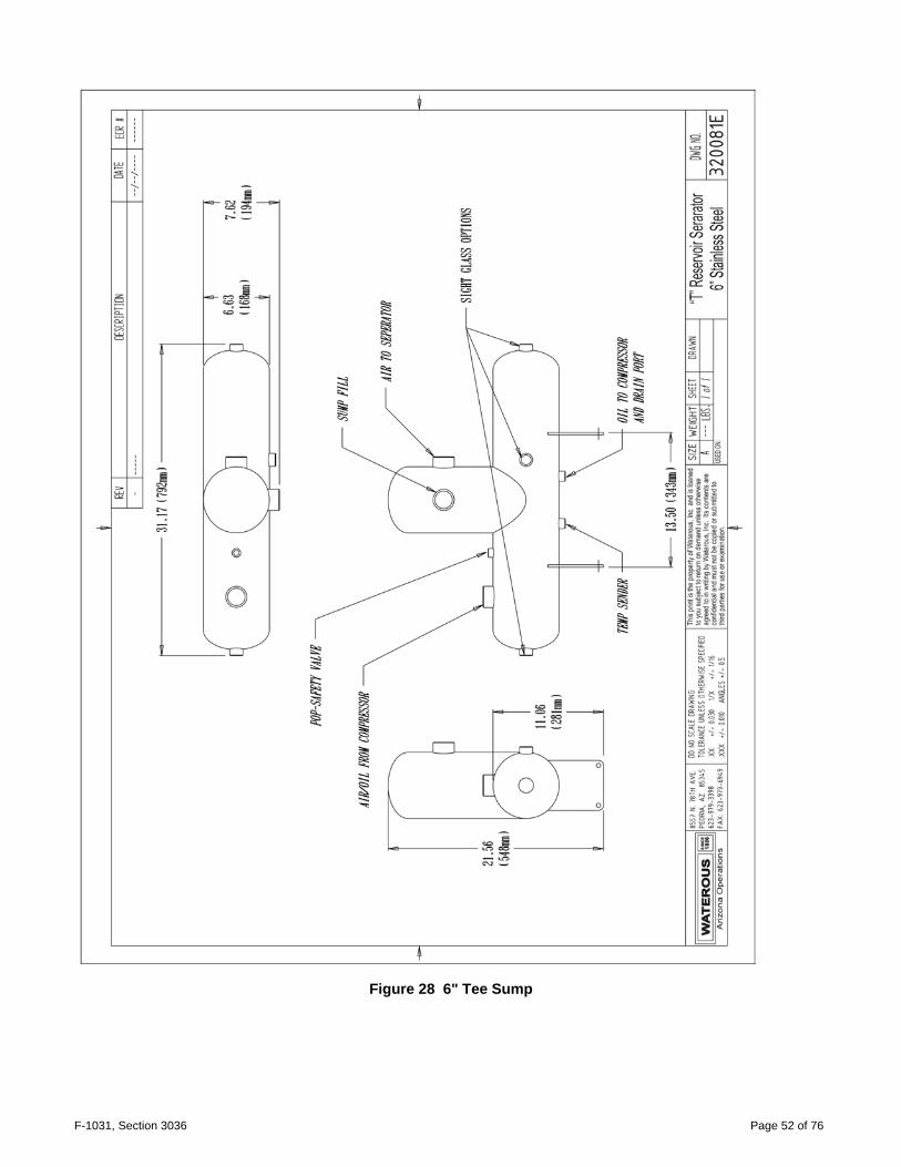
Figure 28 6" Tee Sump
F-1031, Section 3036 Page 53 of 76
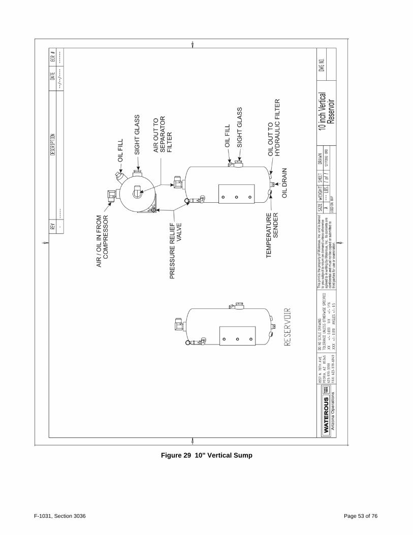
Figure 29 10" Vertical Sump

F-1031, Section 3036 Page 54 of 76
Figure 30 8" Vertical Sump

F-1031, Section 3036 Page 55 of 76
Figure 31 Large Separator Mounting Bracket

F-1031, Section 3036 Page 56 of 76
Figure 32 Hydraulic Schematic, 140 CFM Tee Sump
F-1031, Section 3036 Page 57 of 76
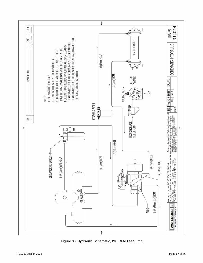
Figure 33 Hydraulic Schematic, 200 CFM Tee Sump

F-1031, Section 3036 Page 58 of 76
Figure 34 Hydraulic Schematic, 140 CFM Vertical Sump
F-1031, Section 3036 Page 59 of 76
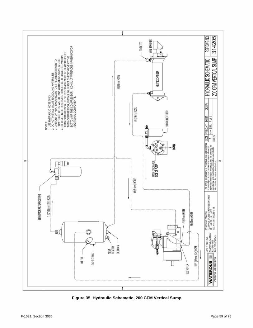
Figure 35 Hydraulic Schematic, 200 CFM Vertical Sump

F-1031, Section 3036 Page 60 of 76
Figure 36 Electrical Schematic, Auto-sync
F-1031, Section 3036 Page 61 of 76
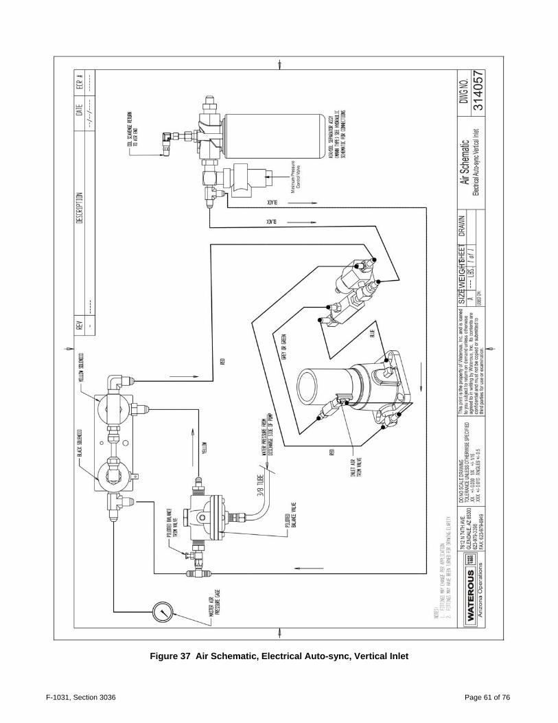
Figure 37 Air Schematic, Electrical Auto-sync, Vertical Inlet
F-1031, Section 3036 Page 62 of 76
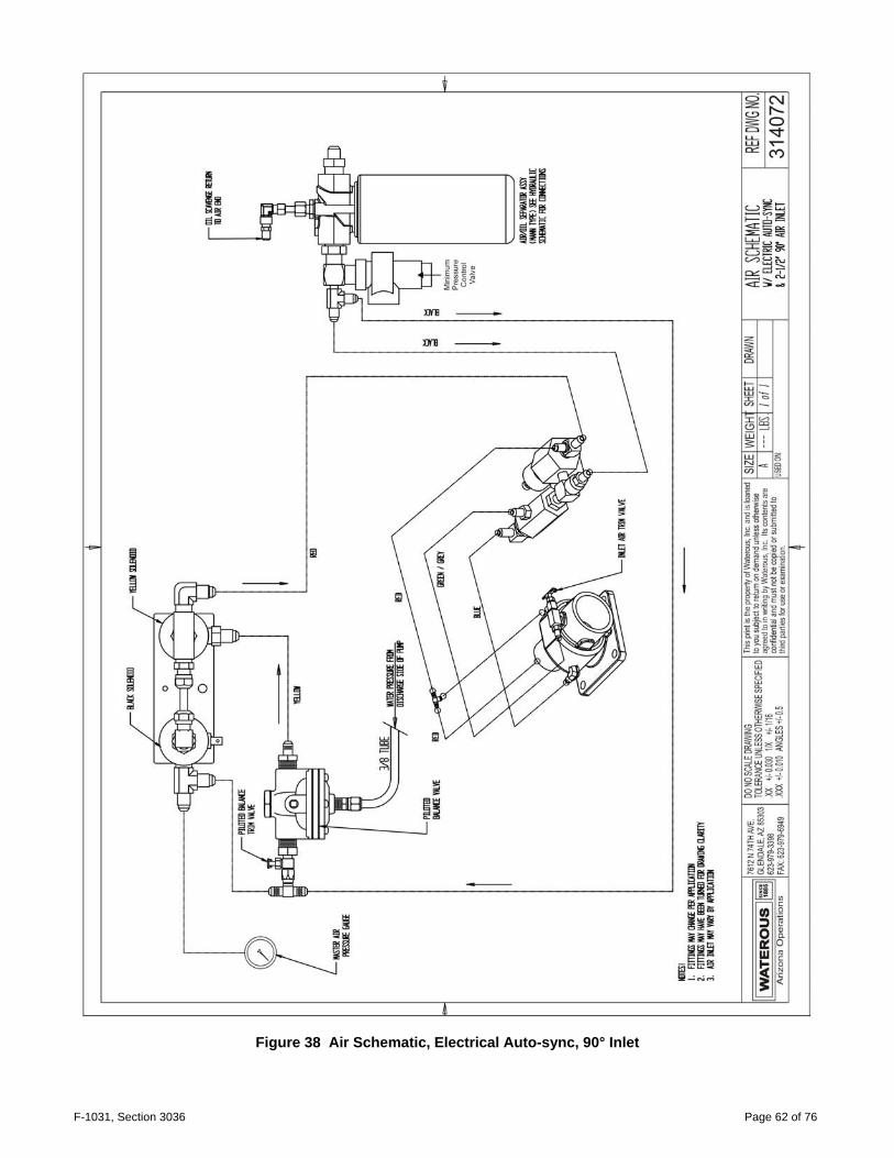
Figure 38 Air Schematic, Electrical Auto-sync, 90° Inlet

F-1031, Section 3036 Page 63 of 76
Figure 39 Air Schematic, Manual Auto-sync, Vertical Inlet

F-1031, Section 3036 Page 64 of 76
Figure 40 Air Schematic, Manual Auto-sync, 90° Inlet

F-1031, Section 3036 Page 65 of 76
Figure 41 Compressor Installation Angles

F-1031, Section 3036 Page 66 of 76
Figure 42 Panel Cutout, Auto-sync, Electrical and Manual
F-1031, Section 3036 Page 67 of 76
SECTION 7. Basic Driveline
Installation Suggestions
A. U-Joint Operating Angles
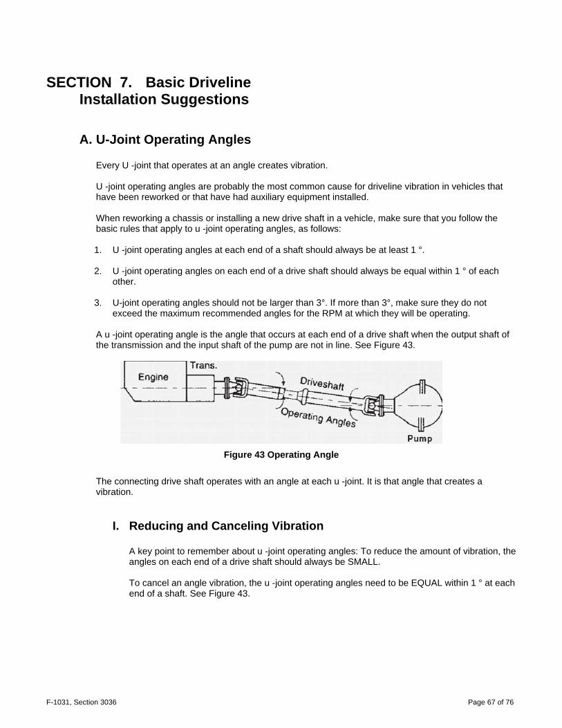
Every U -joint that operates at an angle creates vibration. U -joint operating angles are probably the most common cause for driveline vibration in vehicles that have been reworked or that have had auxiliary equipment installed. When reworking a chassis or installing a new drive shaft in a vehicle, make sure that you follow the basic rules that apply to u -joint operating angles, as follows: 1. U -joint operating angles at each end of a shaft should always be at least 1 °. 2. U -joint operating angles on each end of a drive shaft should always be equal within 1 ° of each
other. 3. U-joint operating angles should not be larger than 3°. If more than 3°, make sure they do not
exceed the maximum recommended angles for the RPM at which they will be operating.
A u -joint operating angle is the angle that occurs at each end of a drive shaft when the output shaft of the transmission and the input shaft of the pump are not in line. See Figure 43.
Figure 43 Operating Angle
The connecting drive shaft operates with an angle at each u -joint. It is that angle that creates a vibration.
I. Reducing and Canceling Vibration A key point to remember about u -joint operating angles: To reduce the amount of vibration, the angles on each end of a drive shaft should always be SMALL. To cancel an angle vibration, the u -joint operating angles need to be EQUAL within 1 ° at each end of a shaft. See Figure 43.

F-1031, Section 3036 Page 68 of 76
B. Single Plane and Compound U-Joint Operating Angles
There are two types of u -joint operating angles, single plane and compound.
I. Single Plane Single plane angles occur when the transmission and pump components are in line when viewed from either the top or side, but not both. Determine the u -joint operating angle in an application where the components are in line when viewed from the top, but not in line when viewed from the side, is as simple as measuring the slope of the components in the side view, and adding or subtracting those slopes to determine the angle. See Figure 44.
Figure 44 Angles in the side view
These angles should be SMALL and equal within 1°. Determine the u -joint operating angles on a shaft that is straight when viewed from the side and offset when viewed from the top requires the use of a special chart (See accompanying chart). In this type of application, the centerlines of the connected components must be parallel when viewed from the top, as shown. These angles should also be SMALL and equal within 1°. See Figure 45.
Figure 45 Angles in the top view
F-1031, Section 3036 Page 69 of 76
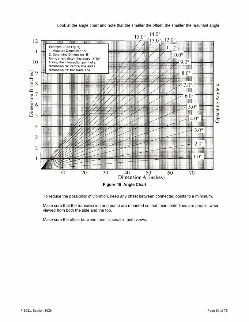
Look at the angle chart and note that the smaller the offset, the smaller the resultant angle.
Figure 46 Angle Chart
To reduce the possibility of vibration, keep any offset between connected points to a minimum. Make sure that the transmission and pump are mounted so that their centerlines are parallel when viewed from both the side and the top. Make sure the offset between them is small in both views.
F-1031, Section 3036 Page 70 of 76
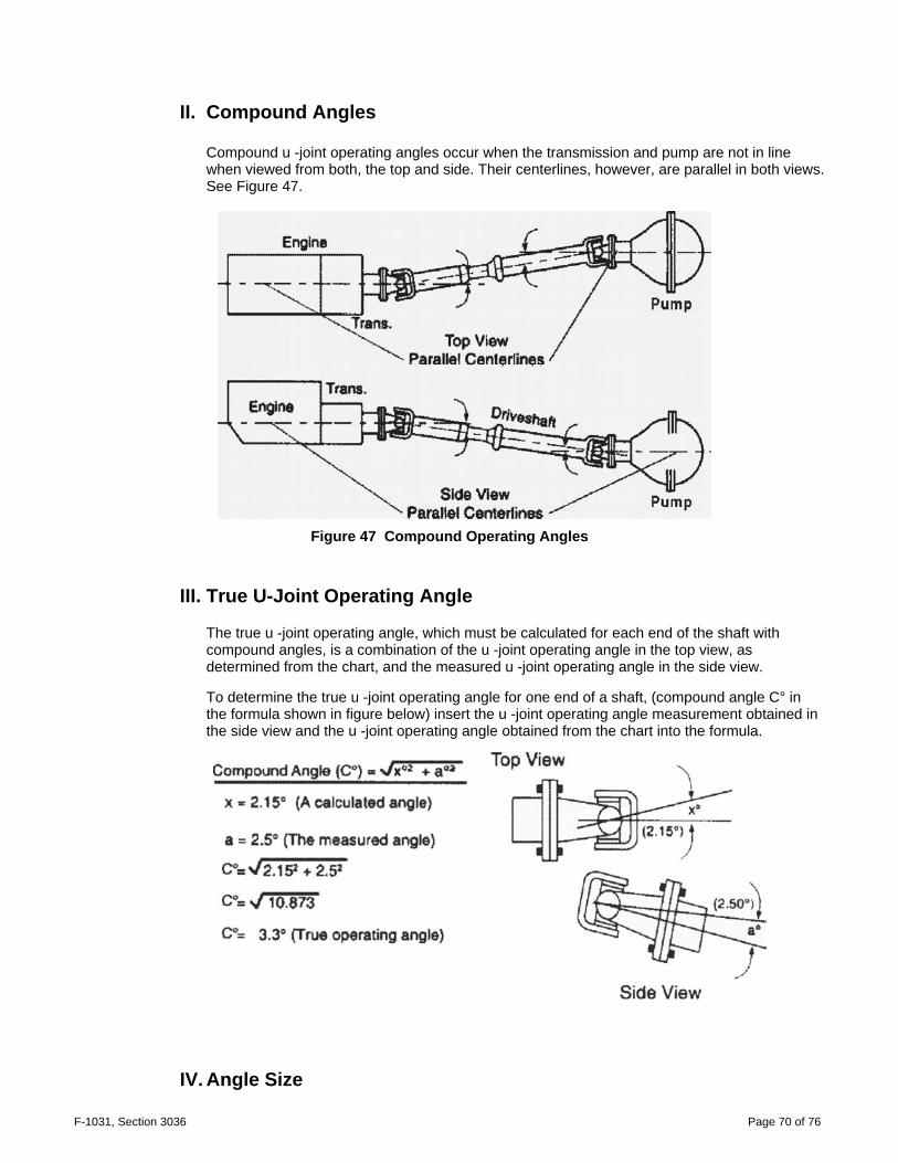
II. Compound Angles
Compound u -joint operating angles occur when the transmission and pump are not in line when viewed from both, the top and side. Their centerlines, however, are parallel in both views. See Figure 47.
Figure 47 Compound Operating Angles
III. True U-Joint Operating Angle
The true u -joint operating angle, which must be calculated for each end of the shaft with compound angles, is a combination of the u -joint operating angle in the top view, as determined from the chart, and the measured u -joint operating angle in the side view. To determine the true u -joint operating angle for one end of a shaft, (compound angle C° in the formula shown in figure below) insert the u -joint operating angle measurement obtained in the side view and the u -joint operating angle obtained from the chart into the formula.
IV. Angle Size
F-1031, Section 3036 Page 71 of 76
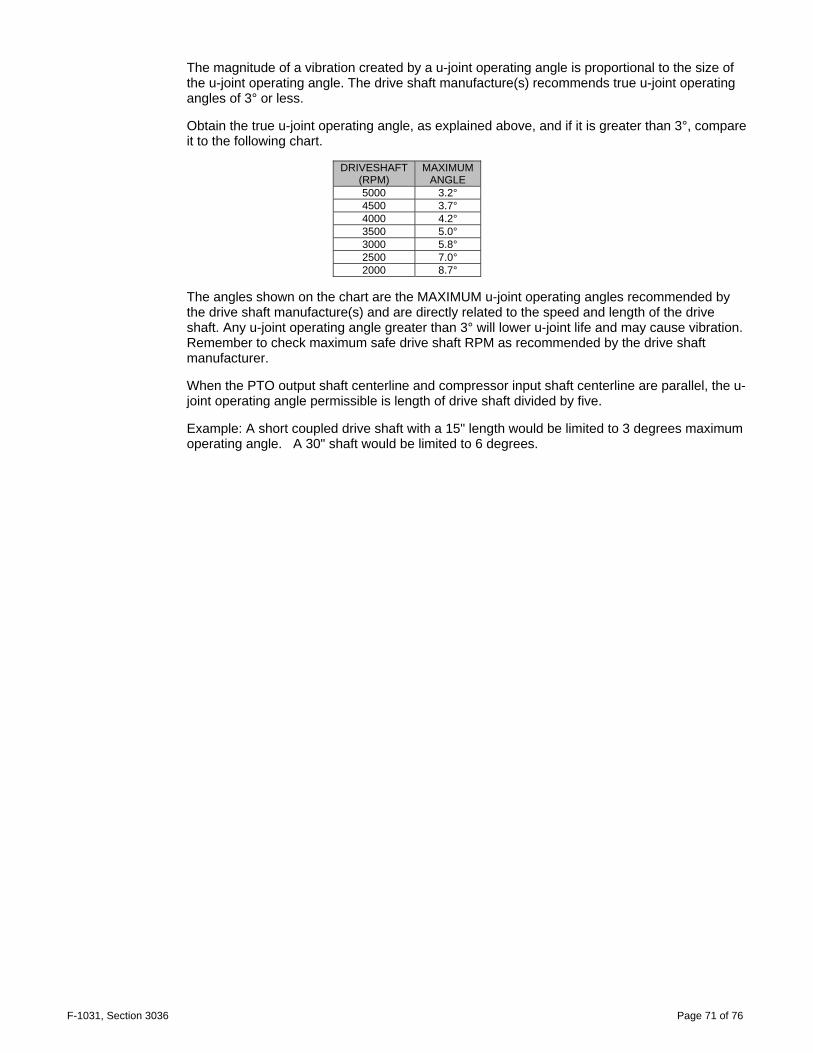
The magnitude of a vibration created by a u-joint operating angle is proportional to the size of the u-joint operating angle. The drive shaft manufacture(s) recommends true u-joint operating angles of 3° or less. Obtain the true u-joint operating angle, as explained above, and if it is greater than 3°, compare it to the following chart.
DRIVESHAFT
(RPM) MAXIMUM
ANGLE 5000 3.2° 4500 3.7° 4000 4.2° 3500 5.0° 3000 5.8° 2500 7.0° 2000 8.7°
The angles shown on the chart are the MAXIMUM u-joint operating angles recommended by the drive shaft manufacture(s) and are directly related to the speed and length of the drive shaft. Any u-joint operating angle greater than 3° will lower u-joint life and may cause vibration. Remember to check maximum safe drive shaft RPM as recommended by the drive shaft manufacturer. When the PTO output shaft centerline and compressor input shaft centerline are parallel, the u-joint operating angle permissible is length of drive shaft divided by five. Example: A short coupled drive shaft with a 15" length would be limited to 3 degrees maximum operating angle. A 30" shaft would be limited to 6 degrees.

F-1031, Section 3036 Page 72 of 76
C. Eliminating Compound Angle Induced Vibrations
Compound u -joint operating angles are one of the most common causes for driveline vibration. To avoid these problems, remember these important considerations: When setting up an application that requires compound u-joint operating angles, always keep the centerlines of the transmission and pump parallel in both views. Always keep the offset between their horizontal and vertical centerlines small.
Note: Centerlines of transmission and axle must be parallel in both top and side views to use this method of
determining true u-joint operating angle. Contact the drive shaft manufacture(s) for technical support if you have an application which cannot be installed with their centerlines parallel.
F-1031, Section 3036 Page 73 of 76
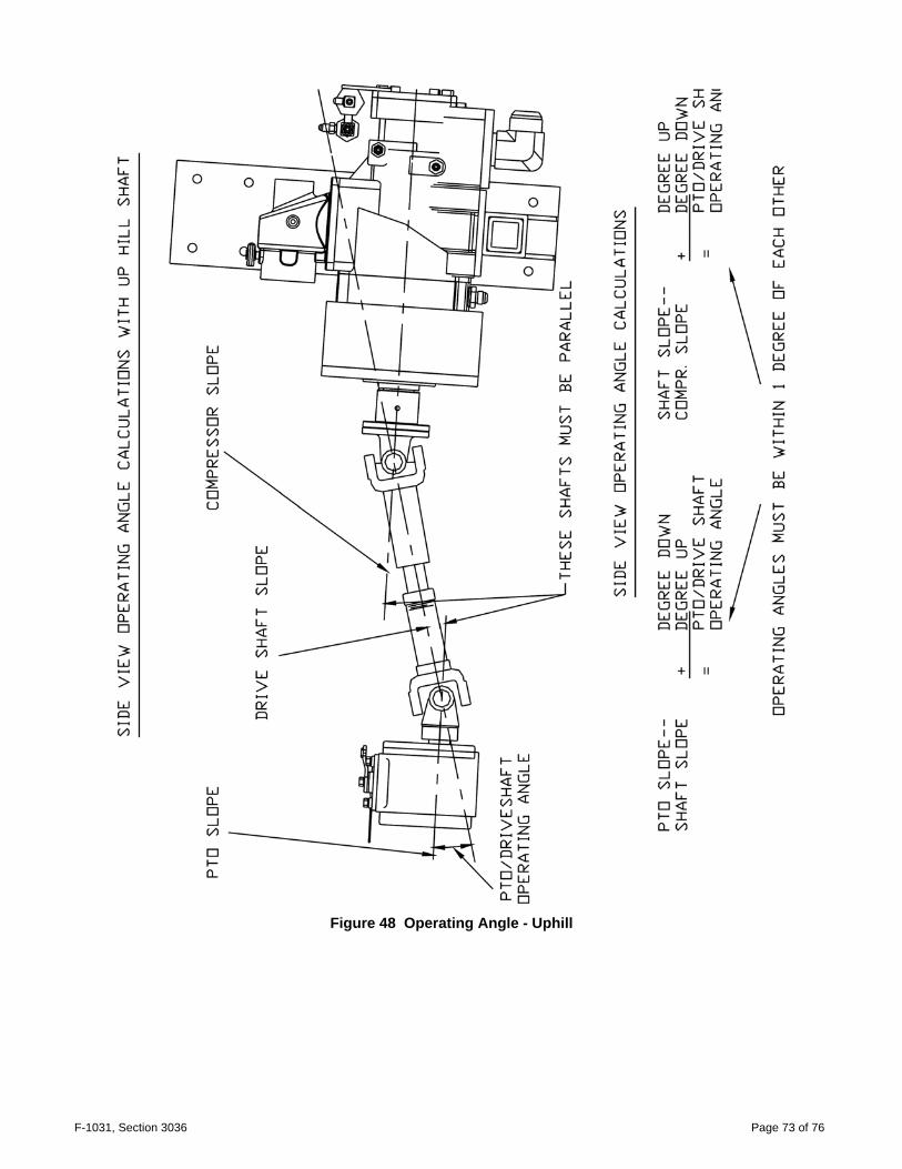
Figure 48 Operating Angle - Uphill

F-1031, Section 3036 Page 74 of 76
Figure 49 Operating Angle - Downhill

F-1031, Section 3036 Page 75 of 76
Figure 50 Driveline Run-out Spec

F-1031, Section 3036 Page 76 of 76
SECTION 8. WATEROUS 5-YEAR LIMITED WARRANTY POLICY WATEROUS warrants, to the original Buyer only, that products manufactured by WATEROUS will be free from defects in material and workmanship under normal use and service for a period of five (5) years from the date the product is first placed in service, or five and one-half (5-1/2) years from the date of shipment by WATEROUS, whichever period shall be the first to expire; provided the Buyer notifies WATEROUS, in writing, of the defect in said product within the warranty period, and said product is found by WATEROUS to be nonconforming with the aforesaid warranty. When required in writing by WATEROUS, defective products must be promptly returned by Buyer to WATEROUS at WATEROUS' plant at South St. Paul, Minnesota, or at such other place as may be specified by WATEROUS, with transportation and other charges prepaid. A Returned Material Authorization (RMA) is required for all products and parts and may be requested by phone, fax, email, or mail. The aforesaid warranty excludes any responsibility or liability of WATEROUS for:
(a) damages or defects due to accident, abuse, misuse, abnormal operating conditions, negligence, accidental causes, use in non-firefighting applications, or improper maintenance, or attributable to written specifications or instructions furnished by Buyer;
(b) defects in products manufactured by others and furnished by WATEROUS hereunder, it being understood and agreed by the parties that the only warranty provided for such products shall be the warranty provided by the manufacturer thereof which, if assignable, WATEROUS will assign to Buyer, if requested by Buyer;
(c) any product or part, altered, modified, serviced or repaired other than by WATEROUS, without its prior written consent; (d) the cost of dismantling, removing, transporting, storing, or insuring the defective product or part and the cost of
reinstallation; and (e) normal wear items (packing, strainers, filters, light bulbs, anodes, intake screens, mechanical seals, etc.).
ALL OTHER WARRANTIES ARE EXCLUDED, WHETHER EXPRESS OR IMPLIED BY OPERATION OF LAW OR OTHERWISE, INCLUDING ALL IMPLIED WARRANTIES OF MERCHANTABILITY OR FITNESS FOR A PARTICULAR PURPOSE. IN NO EVENT, WHETHER AS A RESULT OF BREACH OF CONTRACT, WARRANTY, TORT (INCLUDING NEGLIGENCE), STRICT LIABILITY, OR ANY OTHER CAUSE OF ACTION, SHALL WATEROUS BE LIABLE FOR ANY PUNITIVE, SPECIAL, INCIDENTAL OR CONSEQUENTIAL DAMAGES, OR FOR PERSONAL INJURY OR PROPERTY DAMAGES.
The exclusive remedy of Buyer and the sole liability of WATEROUS, whether based on contract, warranty, tort or any other basis of recovery whatsoever, is expressly limited at the election of WATEROUS to:
(a) the replacement at the agreed point of delivery of any product or part, which upon inspection by WATEROUS or its duly authorized representative, is found not to conform to the limited warranty set forth above, or
(b) the repair of such product or part, or (c) the refund or crediting to Buyer of the net sales price of the defective product or part.
BUYER'S REMEDIES CONTAINED HEREIN ARE EXCLUSIVE OF ANY OTHER REMEDY OTHERWISE AVAILABLE TO BUYER.
Waterous Company 125 Hardman Avenue South South St. Paul, MN 55075 www.waterousco.com