14 multi-cycle mips
TRANSCRIPT

8/13/2019 14 Multi-cycle MIPS
http://slidepdf.com/reader/full/14-multi-cycle-mips 1/65
1
ECE 2500Computer Organization and Architecture
Spring 2012
Multi-cycle MIPS Hardware

8/13/2019 14 Multi-cycle MIPS
http://slidepdf.com/reader/full/14-multi-cycle-mips 2/65
2
The Single Cycle Computer Review

8/13/2019 14 Multi-cycle MIPS
http://slidepdf.com/reader/full/14-multi-cycle-mips 3/65
3
Single Cycle Computer
To recap, let's follow closely how the followinginstruction is executed on this architecture
lw $s0, 12($t3)

8/13/2019 14 Multi-cycle MIPS
http://slidepdf.com/reader/full/14-multi-cycle-mips 4/65
4
lw $s0, 12($t3)
0x1000 0x1004
0x1000 add $t3, $t2, $t3
0x1004 lw $s0, 12($t3)
0x1008 sub $t5, $t2, $t1

8/13/2019 14 Multi-cycle MIPS
http://slidepdf.com/reader/full/14-multi-cycle-mips 5/65
5
lw $s0, 12($t3)
0x1000 0x1004
0x1000 add $t3, $t2, $t3
0x1004 lw $s0, 12($t3)
0x1008 sub $t5, $t2, $t1
add lw
memory access time

8/13/2019 14 Multi-cycle MIPS
http://slidepdf.com/reader/full/14-multi-cycle-mips 6/65
6
lw $s0, 12($t3)
0x1000 0x1004
add lw
$?? $t3
register access time

8/13/2019 14 Multi-cycle MIPS
http://slidepdf.com/reader/full/14-multi-cycle-mips 7/65
7
lw $s0, 12($t3)
0x1000 0x1004
add lw
$?? $t3
alu add time
adr1 $t3 + 12

8/13/2019 14 Multi-cycle MIPS
http://slidepdf.com/reader/full/14-multi-cycle-mips 8/65
8
0x1000 0x1004
add lw
$?? $t3
memory read time(+ mux)
adr1 $t3 + 12
mem($t3 + 12)x
lw $s0, 12($t3)

8/13/2019 14 Multi-cycle MIPS
http://slidepdf.com/reader/full/14-multi-cycle-mips 9/65
9
0x1000 0x1004
add lw
$?? $t3
must be bigger thenregister file write setup time
adr1 $t3 + 12
mem($t3 + 12)x
lw $s0, 12($t3)

8/13/2019 14 Multi-cycle MIPS
http://slidepdf.com/reader/full/14-multi-cycle-mips 10/65
10
Single-Cycle implies a long Critical Path

8/13/2019 14 Multi-cycle MIPS
http://slidepdf.com/reader/full/14-multi-cycle-mips 11/65
11
Critical Path varies with instruction type
add $t3, $t4, $t5

8/13/2019 14 Multi-cycle MIPS
http://slidepdf.com/reader/full/14-multi-cycle-mips 12/65
12
Critical Path varies with instruction type
bne $t3, $t4, 25

8/13/2019 14 Multi-cycle MIPS
http://slidepdf.com/reader/full/14-multi-cycle-mips 13/65
13
The multi-cycle processor
The single cycle processor has a very simple controlscheme BUT has a very long critical path
The critical path varies with the instruction type
Results in inefficient use of clock cycle
Therefore, we will chop the instruction cycle
Multiple shorter cycles per instruction
Vary the number of shorter cycles with the instruction type
Key points to figure out
How to 'chop' logic in cycles
How to modify the single-cycle computer architecture

8/13/2019 14 Multi-cycle MIPS
http://slidepdf.com/reader/full/14-multi-cycle-mips 14/65
14
Splitting a combinational computation
Logic
Register Register
Logic Logic
RegisterRegister
Logic Logic
RegisterRegister
Cycle 1 Cycle 2
Single cycle

8/13/2019 14 Multi-cycle MIPS
http://slidepdf.com/reader/full/14-multi-cycle-mips 15/65
15
Making the transformation to multi-cycle
Register
Add a register at the output of each logic block

8/13/2019 14 Multi-cycle MIPS
http://slidepdf.com/reader/full/14-multi-cycle-mips 16/65
16
Result is 6 small operations
2
1
3
4
5 6
1. Fetch Instruction2. Increment PC
3. Calculate Branch4. Read Register Operands5. ALU Operation6. Fetch Data operand

8/13/2019 14 Multi-cycle MIPS
http://slidepdf.com/reader/full/14-multi-cycle-mips 17/65
17
Merging Logic in multicycle implementations
reg1 reg2
ALU ALU
operation 1 operation 2
reg1 reg2
ALU ALU
operation 1 operation 2reg3
multi-cycle conversion
Two identical ALU used in different clockcycles can be merged into one ALU
Distributing logic over multiple cycles enables reuse!

8/13/2019 14 Multi-cycle MIPS
http://slidepdf.com/reader/full/14-multi-cycle-mips 18/65
18
Merging Logic in multicycle implementations
reg1 reg2
ALU ALU
operation 1 operation 2reg3
ALU
operation 1 operation 2
cycle1/ cycle2
reg1
reg2/3
8/13/2019 14 Multi-cycle MIPS
http://slidepdf.com/reader/full/14-multi-cycle-mips 19/65
19
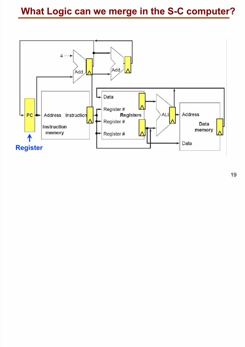
What Logic can we merge in the S-C computer?
Register

8/13/2019 14 Multi-cycle MIPS
http://slidepdf.com/reader/full/14-multi-cycle-mips 20/65
20
What Logic can we merge in the S-C computer?
Register
Merge additions and ALU
Merge memory access

8/13/2019 14 Multi-cycle MIPS
http://slidepdf.com/reader/full/14-multi-cycle-mips 21/65
21
Logic merging results in multi-cycle datapath
Register Registers Registers Registers

8/13/2019 14 Multi-cycle MIPS
http://slidepdf.com/reader/full/14-multi-cycle-mips 22/65
22
Multi-cycle datapath (with multiplexers)
What is the difference between the green and the bluemultiplexers ?

8/13/2019 14 Multi-cycle MIPS
http://slidepdf.com/reader/full/14-multi-cycle-mips 23/65
23
The Single Cycle Computer
Look at the single cycle computer if you're not sure ...

8/13/2019 14 Multi-cycle MIPS
http://slidepdf.com/reader/full/14-multi-cycle-mips 24/65
24
Multi-cycle datapath (with multiplexers)
Green multiplexers accomodate multiple types of MIPS instructions
I-type and R-type have
different destination reg field
Result data is from data memory (lw)
or from ALU (arithmetic op)

8/13/2019 14 Multi-cycle MIPS
http://slidepdf.com/reader/full/14-multi-cycle-mips 25/65
25
Multi-cycle datapath (with multiplexers)
Blue multiplexers support logic reuse during multi-cycle instructions
Memory serves as instruction-memory
and data-memory
ALU does next-PCcalculation and
arithmetic

8/13/2019 14 Multi-cycle MIPS
http://slidepdf.com/reader/full/14-multi-cycle-mips 26/65
26
Multi-cycle controller design
Each instruction can now be mapped to several clockcycles in the multi-cycle controller design
A MIPS instruction will be split into up to 5 executionsteps
Instruction Fetch
Instruction decode and Register Fetch
Execution
Memory access
Memory read completion
In the following, we will map the MIPS instructions tothe above 5 execution steps

8/13/2019 14 Multi-cycle MIPS
http://slidepdf.com/reader/full/14-multi-cycle-mips 27/65
27
Register Transfers and Register Names
IR
MDR
PC
A
B AluOut
We will describe the execution in terms of so-calledregister-transfers between the registers with namesas shown below

8/13/2019 14 Multi-cycle MIPS
http://slidepdf.com/reader/full/14-multi-cycle-mips 28/65
28
Cycle 1: Instruction Fetch
PC <= PC + 4IR <= Memory[PC]

8/13/2019 14 Multi-cycle MIPS
http://slidepdf.com/reader/full/14-multi-cycle-mips 29/65
29
Cycle 2: Instruction Decode and Reg Fetch
A <= Reg[IR[25:21]]B <= Reg[IR[20:16]]
AluOut <= PC + (SignExt(IR[15:0]) << 2)
Optimistic:may/ may notbe needed

8/13/2019 14 Multi-cycle MIPS
http://slidepdf.com/reader/full/14-multi-cycle-mips 30/65
30
Cycle 3: Execution (for Branch)
if (A == B) PC <= AluOutThis completes the Branch Instruction

8/13/2019 14 Multi-cycle MIPS
http://slidepdf.com/reader/full/14-multi-cycle-mips 31/65
31
Cycle 3: Execution (for R-type)
AluOut <= A op B

8/13/2019 14 Multi-cycle MIPS
http://slidepdf.com/reader/full/14-multi-cycle-mips 32/65
32
Cycle 4: memory Access (for R-type)
Reg[IR[15:11]] <= AluOut
This completes the R-type instruction

8/13/2019 14 Multi-cycle MIPS
http://slidepdf.com/reader/full/14-multi-cycle-mips 33/65
33
Cycle 3: Execution (for lw/sw)
AluOut <= A + SignExtend(IR[15:0])

8/13/2019 14 Multi-cycle MIPS
http://slidepdf.com/reader/full/14-multi-cycle-mips 34/65
34
Cycle 4: memory Access (for lw/sw)
lw instruction - MDR <= Memory[AluOut]sw instruction - Memory[AluOut] <= B
This completes sw instruction

8/13/2019 14 Multi-cycle MIPS
http://slidepdf.com/reader/full/14-multi-cycle-mips 35/65
35
Cycle 5: memory completion
Reg[IR[20:16]] <= MDR
This completes the lw instruction
S

8/13/2019 14 Multi-cycle MIPS
http://slidepdf.com/reader/full/14-multi-cycle-mips 36/65
36
RTL Summary
InstructionFetch
InstructionDecode
Execution
Memory Access
MemoryCompletion
R-type lw sw branch
IR <= Memory[PC]PC <= PC + 4
A <= Reg[IR[25:21]]; B <= Reg[IR[20:16]] AluOut <= PC + SignExt(IR[15:0] << 2)
AluOut<= A op B AluOut<= A +
SignExt(IR[15:0])if (A==B)
PC <= AluOut
Reg[IR[15:11]]<= AluOut
MDR <=Mem[AluOut]
Mem[AluOut]<= B
Reg[IR[20:16]]<= MDR
Instructions take 3, 4, or 5 cycles
This table can be used to design the controller
M lti C l D t th ( ith t l i l )

8/13/2019 14 Multi-cycle MIPS
http://slidepdf.com/reader/full/14-multi-cycle-mips 37/65
37
Multi-Cycle Datapath (with control signals)
H t t th t l i l ?

8/13/2019 14 Multi-cycle MIPS
http://slidepdf.com/reader/full/14-multi-cycle-mips 38/65
38
How to generate these control signals ?
InstructionFetch
InstructionDecode
Execution
Memory Access
MemoryCompletion
R-type lw sw branch
IR <= Memory[PC]PC <= PC + 4
A <= Reg[IR[25:21]]; B <= Reg[IR[20:16]] AluOut <= PC + SignExt(IR[15:0] << 2)
AluOut<= A op B AluOut<= A +
SignExt(IR[15:0])if (A==B)
PC <= AluOut
Reg[IR[15:11]]<= AluOut
MDR <=Mem[AluOut]
Mem[AluOut]<= B
Reg[IR[20:16]]<= MDR
Example: let's find the control signals for
AluOut <= A + SignExt(IR[15:0])
C t l i l f R i t T f

8/13/2019 14 Multi-cycle MIPS
http://slidepdf.com/reader/full/14-multi-cycle-mips 39/65
39
Control signals for Register-Transfers
X 0 0 0 X 0 1
X 2 add
Fi it St t M hi

8/13/2019 14 Multi-cycle MIPS
http://slidepdf.com/reader/full/14-multi-cycle-mips 40/65
40
Finite State Machines
Generate a (possibly conditional) sequence of controlsignals
A Finite State Machine (FSM) is an abstractrepresentation of a control sequence
An FSM models a machine can be in several different states
State transitions bring the machine from one state into theother
A single state is designated as an initial state
An FSM is captured by a graph, with nodes representing
states and edges representing state transitions
Fi it St t M hi S i

8/13/2019 14 Multi-cycle MIPS
http://slidepdf.com/reader/full/14-multi-cycle-mips 41/65
41
Finite State Machine: Sequencing
S0 S1 S2
This machine has three states (s0, s1, s2) and startsout in s0
When in s0, it will always transition into s1, and nextinto s2
Fi it St t M hi S i

8/13/2019 14 Multi-cycle MIPS
http://slidepdf.com/reader/full/14-multi-cycle-mips 42/65
42
Finite State Machine: Sequencing
S0 S1 S2
In our discussion, state transitions are timed .
Each clock cycle, the FSM will make a single statetransition
cycle 0 cycle 1 cycle 2
cycle 3 cycle 4 cycle 5
...
Fi it St t M hi S i

8/13/2019 14 Multi-cycle MIPS
http://slidepdf.com/reader/full/14-multi-cycle-mips 43/65
43
Finite State Machine: Sequencing
S0
S1
S2
State transitions can be conditional when decision-making is needed
Controllermodeledwith FSM
whena==0
whena==1
Datapath generates
a state transition condition a
a
FSM for the m lti c cle datapath

8/13/2019 14 Multi-cycle MIPS
http://slidepdf.com/reader/full/14-multi-cycle-mips 44/65
44
FSM for the multi-cycle datapath
Each loop in this graphrepresents the execution of a
single instruction 5 loops for 5 instruction types:
lw, sw, R-type, conditional-branch, jump
We did not discuss jump
Each state shows the value ofthe control signals
Each state transition showsthe condition that triggers it
If nothing is shown, transitionis taken unconditionally atstart of the next clock cycle.
Multicycle Datapath Finite State Machine

8/13/2019 14 Multi-cycle MIPS
http://slidepdf.com/reader/full/14-multi-cycle-mips 45/65
45
Multicycle Datapath Finite State Machine
Start Fetch Decode
Write Back
MemoryLoad
Exec Load/Store
0 1
2
3
4
5
6
7
8 9
Exec R-Type
MemoryStore
MemoryR-Type
Exec branch
Exec jump
FSM corresponds to RTL summary table

8/13/2019 14 Multi-cycle MIPS
http://slidepdf.com/reader/full/14-multi-cycle-mips 46/65
46
FSM corresponds to RTL summary table
1 2
3
InstructionFetch
InstructionDecode
Execution
Memory Access
Memory
Completion
R-type lw sw branch
IR <= Memory[PC]PC <= PC + 4
A <= Reg[IR[25:21]]; B <= Reg[IR[20:16]] AluOut <= PC + SignExt(IR[15:0] << 2)
AluOut<= A op B AluOut<= A +
SignExt(IR[15:0])if (A==B)
PC <= AluOut
Reg[IR[15:11]]<= AluOut
MDR <=Mem[AluOut]
Mem[AluOut]<= B
Reg[IR[20:16]]
<= MDR
4
5
123
4
5
FSM corresponds to RTL summary table

8/13/2019 14 Multi-cycle MIPS
http://slidepdf.com/reader/full/14-multi-cycle-mips 47/65
47
FSM corresponds to RTL summary table
1 2
3
InstructionFetch
InstructionDecode
Execution
Memory Access
Memory
Completion
R-type lw sw branch
IR <= Memory[PC]PC <= PC + 4
A <= Reg[IR[25:21]]; B <= Reg[IR[20:16]] AluOut <= PC + SignExt(IR[15:0] << 2)
AluOut<= A op B AluOut<= A +
SignExt(IR[15:0])if (A==B)
PC <= AluOut
Reg[IR[15:11]]<= AluOut
MDR <=Mem[AluOut]
Mem[AluOut]<= B
Reg[IR[20:16]]
<= MDR
4
1234
FSM Implementation

8/13/2019 14 Multi-cycle MIPS
http://slidepdf.com/reader/full/14-multi-cycle-mips 48/65
48
FSM Implementation
State Encoding: represent each state with a uniquenumber.
N states => log2(N) bits required
Next-state logic & output logic are combinational circuits
StateRegister
Next-stateLogic
OutputLogic
toDatapath
fromDatapath
log2(# states)
Microprogramming

8/13/2019 14 Multi-cycle MIPS
http://slidepdf.com/reader/full/14-multi-cycle-mips 49/65
49
Microprogramming
It's not always possible or desirable to hardcode the next-state logic & output logic
Example: Suppose you want a programmable instruction set, i.e.the possibility to define new instructions in a computer
Solution: Microprogramming
Thus, a MIPS program is made with instructions
Each instruction is made with micro-instructions
• Some computers make each micro-instruction with nano-instructions
– ...
toDatapath
MicroProgram AddressRegister
Next-address
Logic
MicroprogramMemoryfrom
Datapath
This is a writableMEMORY
(not hardwired gateslike an FSM)
After all How many Cycles Per Instruction (CPI)?

8/13/2019 14 Multi-cycle MIPS
http://slidepdf.com/reader/full/14-multi-cycle-mips 50/65
50
After all, How many Cycles Per Instruction (CPI)?
The average program contains 25% load, 50%arithmetic, 10% store, 15% branches
Load: 5 cycles, Store: 4 cycles, Arith: 4 cycles, Branch:3 cycles
Therefore, CPI , cycles per instruction:
CPI = 0.25*5 + 0.5*4 + 0.1*4 + 0.15*3 = 4.1 cycles/instruction
You can predict the cycle-true behavior of a programby looking at the sequence of instructions
Recap: The multi cycle MIPS datapath

8/13/2019 14 Multi-cycle MIPS
http://slidepdf.com/reader/full/14-multi-cycle-mips 51/65
51
Recap: The multi-cycle MIPS datapath
Single-cycle datapath
ALU with Sign-extendInstruction Memory
Data MemoryRegister FileBranch Address adderNext-PC adder+ Program Counter Reg
Multi-cycle datapath
ALU with Sign-extendMemoryRegister File
+ Program Counter Reg+ A and B Reg+ ALUOut Reg+ Memory Data Reg+ Instruction Reg
Insert Registers after each logic block
Merge logic & registers used inexclusive clock cycles
Multi cycle datapath

8/13/2019 14 Multi-cycle MIPS
http://slidepdf.com/reader/full/14-multi-cycle-mips 52/65
52
Multi-cycle datapath
Multi-cycle Implementation of MIPS instructions

8/13/2019 14 Multi-cycle MIPS
http://slidepdf.com/reader/full/14-multi-cycle-mips 53/65
53
Multi-cycle Implementation of MIPS instructions
R-type instructionslw/ sw instructionsconditional branch
MIPS Instructions
3-cycleinstruction
4-cycleinstruction
5-cycleinstruction
Register Transfers
= operations for which the source andthe destination is defined by one
of the following hardware registers:PC, IR, MDR, A, B, AluOut
beq R-type
sw
lw
An RT takes 1 clock cycle Several RT can execute in parallel
implementedusing
Example: add $s0 $t0 $t1

8/13/2019 14 Multi-cycle MIPS
http://slidepdf.com/reader/full/14-multi-cycle-mips 54/65
54
Example: add $s0, $t0, $t1
IR <= Memory[PC]PC <= PC + 4
A <= Reg[IR[25:21]]B <= Reg[IR[20:16]] AluOut <= PC + SignExt(IR[15:0] << 2)
AluOut <= A op B
Reg[IR[15:11]] <= AluOut
What happensRTL
Cycle 1
Cycle 2
Cycle 3
Cycle 4
Example: add $s0 $t0 $t1

8/13/2019 14 Multi-cycle MIPS
http://slidepdf.com/reader/full/14-multi-cycle-mips 55/65
55
Example: add $s0, $t0, $t1
IR <= Memory[PC]PC <= PC + 4
A <= Reg[IR[25:21]]B <= Reg[IR[20:16]] AluOut <= PC + SignExt(IR[15:0] << 2)
AluOut <= A op B
Reg[IR[15:11]] <= AluOut
IR <= 'add $s0, $t0, $t1'PC <= PC + 4
A <= $t0B <= $t1 AluOut <= garbage
AluOut <= $t0 '+' $t1
$s0 <= AluOut
What happensRTL
Cycle 1
Cycle 2
Cycle 3
Cycle 4
Example: add $s0 $t0 $t1

8/13/2019 14 Multi-cycle MIPS
http://slidepdf.com/reader/full/14-multi-cycle-mips 56/65
56
Example: add $s0, $t0, $t1
Cycle 1: IR <= Memory[PC]; PC <= PC + 4
Example: add $s0 $t0 $t1

8/13/2019 14 Multi-cycle MIPS
http://slidepdf.com/reader/full/14-multi-cycle-mips 57/65
57
Example: add $s0, $t0, $t1
Cycle 1: IR <= Memory[PC]; PC <= PC + 4
0 1 0 1 X 0 0
X 01 00
Example: add $s0 $t0 $t1

8/13/2019 14 Multi-cycle MIPS
http://slidepdf.com/reader/full/14-multi-cycle-mips 58/65
58
Example: add $s0, $t0, $t1
Cycle 2: A <= Reg[IR[25:21]]; B <= Reg[IR[20:16]]; AluOut <= PC + SignExt(IR[15:0] << 2)
0 1 0 1 X 0 0
X 01 00
Example: add $s0 $t0 $t1

8/13/2019 14 Multi-cycle MIPS
http://slidepdf.com/reader/full/14-multi-cycle-mips 59/65
59
Example: add $s0, $t0, $t1
Cycle 2: A <= Reg[IR[25:21]]; B <= Reg[IR[20:16]]; AluOut <= PC + SignExt(IR[15:0] << 2)
0 1 0 1 X 0 0
X 01 00
X 0 0 0 X 0 0
X 11 00
Example: add $s0, $t0, $t1

8/13/2019 14 Multi-cycle MIPS
http://slidepdf.com/reader/full/14-multi-cycle-mips 60/65
60
Example: add $s0, $t0, $t1
Cycle 3: AluOut <= A op B
0 1 0 1 X 0 0
X 01 00
X 0 0 0 X 0 0
X 11 00
Example: add $s0, $t0, $t1

8/13/2019 14 Multi-cycle MIPS
http://slidepdf.com/reader/full/14-multi-cycle-mips 61/65
61
Example: add $s0, $t0, $t1
Cycle 3: AluOut <= A op B
0 1 0 1 X 0 0
X 01 00
X 0 0 0 X 0 0
X 11 00
X 0 0 0 X 0 1
X 00 10
Example: add $s0, $t0, $t1

8/13/2019 14 Multi-cycle MIPS
http://slidepdf.com/reader/full/14-multi-cycle-mips 62/65
62
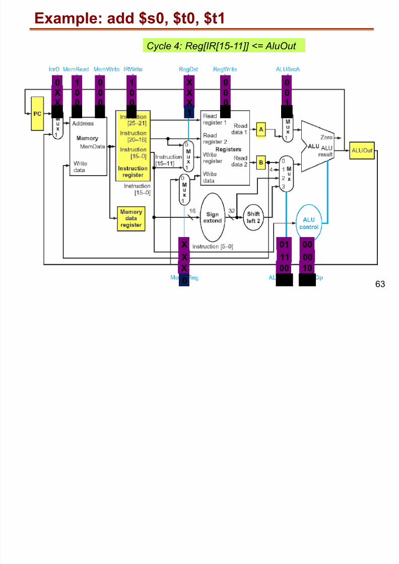
Example: add $s0, $t0, $t1
Cycle 4: Reg[IR[15-11]] <= AluOut
0 1 0 1 X 0 0
X 01 00
X 0 0 0 X 0 0
X 11 00
X 0 0 0 X 0 1
X 00 10
Example: add $s0, $t0, $t1
8/13/2019 14 Multi-cycle MIPS
http://slidepdf.com/reader/full/14-multi-cycle-mips 63/65
63
Example: add $s0, $t0, $t1
Cycle 4: Reg[IR[15-11]] <= AluOut
0 1 0 1 X 0 0
X 01 00
X 0 0 0 X 0 0
X 11 00
X 0 0 0 X 0 1
X 00 10
X 0 0 0 1 1 X
0 XX XX
Multi-cycle control

8/13/2019 14 Multi-cycle MIPS
http://slidepdf.com/reader/full/14-multi-cycle-mips 64/65
64
Multi cycle control
Multi-cycle control boils down to generating sequencesof control bits for the datapath.
0 1 0 1 X 0 0 X 01 00X 0 0 0 X 0 0 X 11 00X 0 0 0 X 0 1 X 00 10X 0 0 0 1 1 X 0 XX XX
Cycle 1Cycle 2Cycle 3Cycle 4
The sequence only depends on the value of theopcode field (IR[31:26]).
Multi-cycle controllerclock
control-bits for the datapathopcode field
To execute add $s0, $t0, $t1, generate the following bits
Summary for the multi-cycle processors

8/13/2019 14 Multi-cycle MIPS
http://slidepdf.com/reader/full/14-multi-cycle-mips 65/65
Summary for the multi cycle processors
Single cycle processor has long, variable critical path
Split critical path by introducing registers Merge logic when similar functions used in separate
cycles
Instruction execution with Register Transfers
Capture control in a Finite State Machine
Performance Measure is CPI = Cycles per Instruction