14 data link control
TRANSCRIPT
CS 408Computer Networks
Chapter 14: Data Link Control
Announcements• Midterm: November 25, Tuesday, 10:40 – 12:30
— in FASS G062 (FASS auditorium)• Exam will be closed book, closed notes
— calculators are allowed— you are responsible all topics I covered in the class even if some of
them are not in the book (I sometimes used other books) and not in the ppt files (I sometimes used board and showed applications on the computer)• I prepared some handouts for the topics that I covered from other
books (available at SUCourse under "resources") but I do not promise any completeness
• There really are some parts that I only covered on the board

Flow Control• In Data Link Layer, we deal with issues related
to point to point links—Flow control is one of these issues
• Flow control is needed since the sending entity should not overwhelm the receiving entity—Recipient needs some time to process incoming
packets—If sender sends faster than recipient processes, then
buffer overflow occurs• flow control prevents buffer overflow
Performance Metrics and Delays (Section 5.3)• Transmission time (delay)
—Time taken to emit all bits into medium• Propagation time (delay)
—Time for a bit to traverse the link• Processing time (delay)
—time spent at the recipient or intermediate node for processing
• Queuing time (delay)—waiting time at the queue to be sent out

Model of Frame Transmission
transmission time
propagation time

Stop and Wait Flow Control• Source transmits frame• Destination receives frame and replies with
acknowledgement (ACK)• Source waits for ACK before sending next frame• Destination can stop flow by not sending ACK• Works well for large frames• Inefficient for smaller frames
Stop and Wait Flow Control• However, generally large block of data split into
small frames —Called “Fragmentation”
• Limited buffer size at receiver• Errors detected sooner (when whole frame received)
– On error, retransmission of smaller frames is needed• Prevents one station occupying medium for long periods
• Channel Utilization is higher when—the transmission time is longer than the propagation time—frame length is larger than the bit length of the link—actually last two expressions mean the same—see the derivations on board
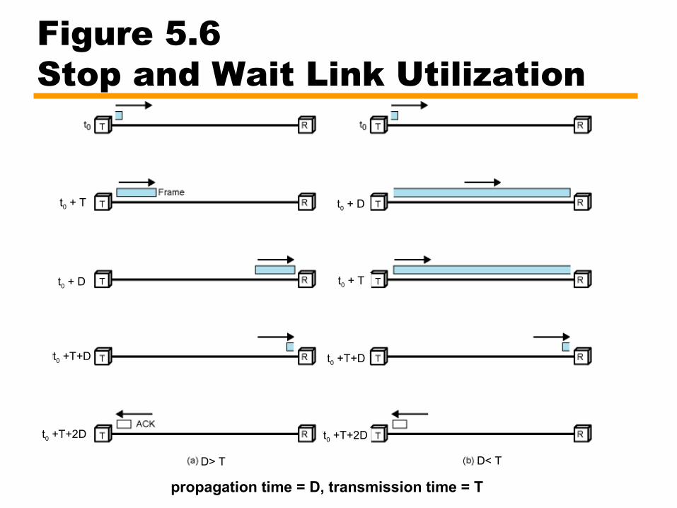
Figure 5.6 Stop and Wait Link Utilization
propagation time = D, transmission time = T
t0 + T
t0 + Tt0 + D
t0 + D
t0 +T+D t0 +T+D
t0 +T+2D t0 +T+2D
D> T D< T
Sliding Window Flow Control• The problem of “Stop and Wait” is not able to send
multiple packets• Sliding Window Protocol allows multiple frames to be in
transit• Receiver has buffer of W (called window size) frames• Transmitter can send up to W frames without ACK• Each frame is numbered
—Sequence number bounded by size of the sequence number field (k bits)
—thus frames are numbered modulo 2k (0 … 2k-1)
• ACK includes number of next frame expected
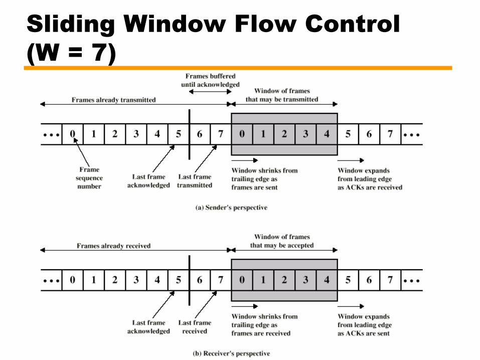
Sliding Window Flow Control(W = 7)
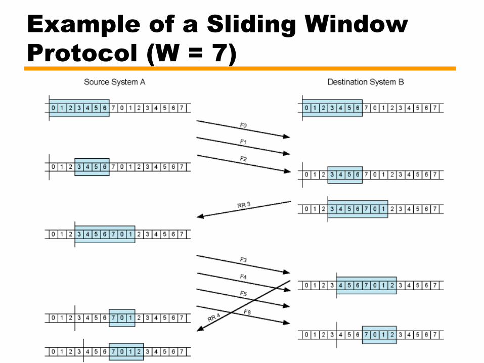
Example of a Sliding Window Protocol (W = 7)

Sliding Window Enhancements in Implementation• Receiver can acknowledge frames without
permitting further transmission (Receive Not Ready)—Must send a normal acknowledgement to resume
• If the link is duplex, use piggybacking—Send data and ack together in one frame
• frame has both data and ack fields
—If no data to send, use acknowledgement frame—If data but no acknowledgement to send, send last
acknowledgement number again
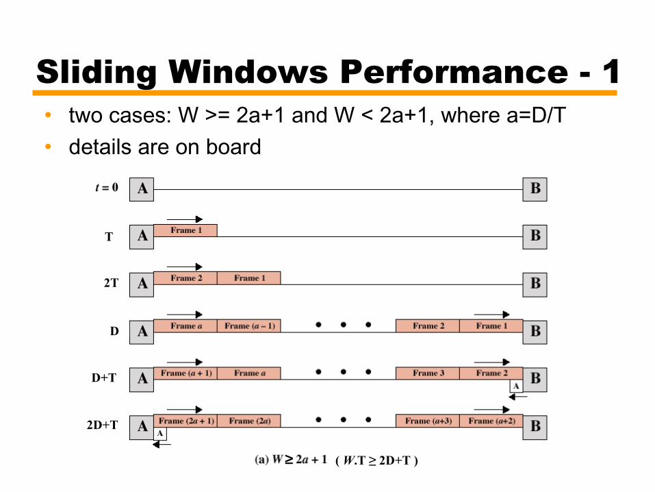
Sliding Windows Performance - 1• two cases: W >= 2a+1 and W < 2a+1, where a=D/T• details are on board
≥
T
2T
D
D+T
2D+T
( W.T ≥ 2D+T )
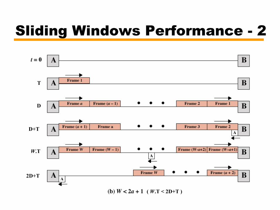
Sliding Windows Performance - 2
T
W.T
D
D+T
2D+T
( W.T < 2D+T )
END OF MIDTERM EXAM• The rest of this ppt file is not in the midterm
exam coverage
Error Detection and Control• So far we have seen flow control mechanisms
where frames are transmitted without errors—in real life any transmission facility may introduce
errors• So we have to
—detect errors—if possible, correct errors (not in the scope of CS 408) —adopt flow control algorithms such that erroneous
frames are retransmitted

Types of Errors• Single bit errors
—isolated errors—affects (flips) one bit, nearby bits are not altered—not so common in real life
• Burst errors—a sequence of bits are affected—most common case—a burst error of length B is a contiguous sequence of
B bits in which the first and the last and some intermediate bits are erroneously flipped.
• not necessarily all bits between the first and the last one
Error Detection• Additional bits added by transmitter as error
detection code—receiver checks this code
• Parity—single bit added to the end of the data—Value of parity bit is such that data and parity have
even (even parity) or odd (odd parity) number of ones—Even number of bit errors goes undetected
• thus not so useful
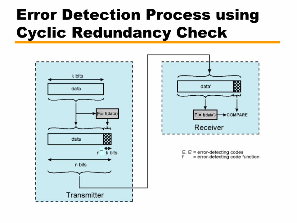
Error Detection Process using Cyclic Redundancy Check
-
F= F’=

Cyclic Redundancy Check (CRC)• For a data block of k bits, transmitter generates n-
k bit frame check sequence (FCS) and appends it to the end of the data bits
• Transmits n bits, which is exactly divisible by some number (generator)—the length of the generator is n-k+1 and first and last
bits are 1• Receiver divides the received frame by generator
—If no remainder, assume no error• Division is binary division (not the same as
integer or real division)• See board for the math details and example

Cyclic Redundancy Check (CRC)• Standard CRCs (generators are standard)
—checks all single, double and odd number of errors—checks all burst errors with length less than or equal
to the length of FCS (n-k)—checks most of the burst errors of longer length
• for bursts of length n-k+1 (length of generator), probability of an undetected error is 1/2n-k-1
• for longer bursts, probability of an undetected error is 1/2n-k

Error Control• Actions to be taken against
—Lost frames—Damaged frames
• Automatic repeat request (ARQ) mechanism components—Error detection—Positive acknowledgment—Retransmission after timeout—Negative acknowledgement and retransmission
Automatic Repeat Request (ARQ)• Stop-and-wait ARQ• Go-back-N ARQ• Selective-reject (selective retransmission) ARQ

Stop and Wait ARQ• Source transmits single frame• Wait for ACK• If received frame is damaged, discard it
—If transmitter receives no ACK within timeout, retransmits
• If ACK damaged,transmitter will not recognize it—Transmitter will retransmit after timeout—Receiver gets two copies of frame, but disregards
one of them—Use ACK0 and ACK1
• ACKi means “I am ready to receive frame i”
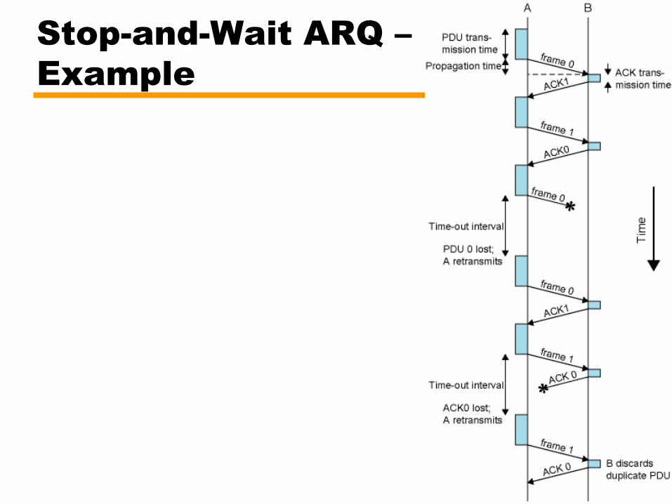
Stop-and-Wait ARQ – Example

Stop and Wait - Pros and Cons• Simple• Inefficient
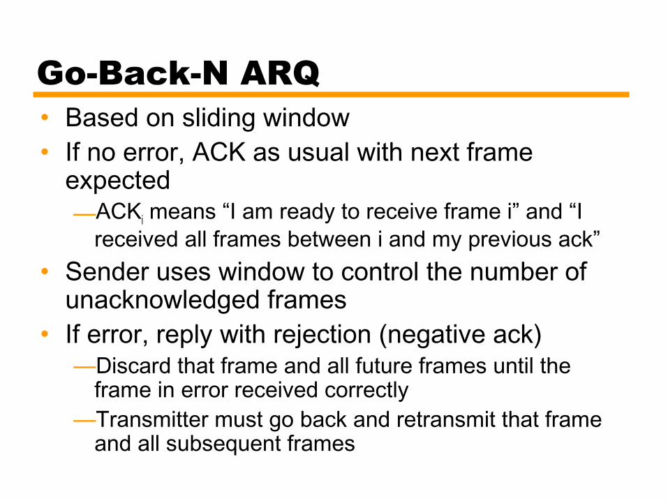
Go-Back-N ARQ• Based on sliding window• If no error, ACK as usual with next frame
expected—ACKi means “I am ready to receive frame i” and “I
received all frames between i and my previous ack”• Sender uses window to control the number of
unacknowledged frames• If error, reply with rejection (negative ack)
—Discard that frame and all future frames until the frame in error received correctly
—Transmitter must go back and retransmit that frame and all subsequent frames

Go-Back-N ARQ - Damaged Frame• Receiver detects error in frame i• Receiver sends “reject i”• Transmitter gets “reject i”• Transmitter retransmits frame i and all
subsequent frames

Go-Back-N ARQ - Lost Frame (1)• Frame i lost• Transmitter sends frame i+1• Receiver gets frame i+1 out of sequence• Receiver sends “reject i”• Transmitter goes back to frame i and
retransmits it and all subsequent frames

Go-Back-N ARQ- Lost Frame (2)• Frame i lost and no additional frame sent• Receiver gets nothing and returns neither
acknowledgment nor rejection• Transmitter times out and sends
acknowledgment frame with P bit set to 1 (this is actually a command for ack request)—Receiver interprets this as an ack request command
which it acknowledges with the number of the next frame it expects (i )
• Transmitter then retransmits frame i
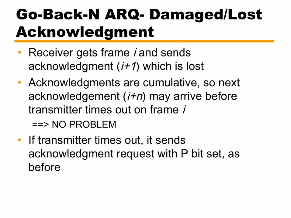
Go-Back-N ARQ- Damaged/Lost Acknowledgment• Receiver gets frame i and sends
acknowledgment (i+1) which is lost• Acknowledgments are cumulative, so next
acknowledgement (i+n) may arrive before transmitter times out on frame i ==> NO PROBLEM
• If transmitter times out, it sends acknowledgment request with P bit set, as before
Go-Back-N ARQ- Damaged Rejection• As in lost frame (2)
—sender asks the receiver the last frame received and continue by retransmitting next frame

Go-Back-N ARQ - Example

Selective Reject• Also called selective retransmission• Only rejected frames are retransmitted• Subsequent frames are accepted by the
receiver and buffered• Minimizes retransmissions• Receiver must maintain large enough buffer• Complex system

Selective Reject -Diagram

Issues• RR with P=1 is from HDLC standard
—pure protocol just have retransmissions after timeout• as explained in Tanenbaum

Issues – Window Size• Given n-bit sequence numbers, what is Max
window size?—go-back-n ARQ 2n-1
• Why?• what about receiver’s window size?
– It is 1, why?
—selective-reject(repeat) 2n-1
• Why?
• See the reasons on the board
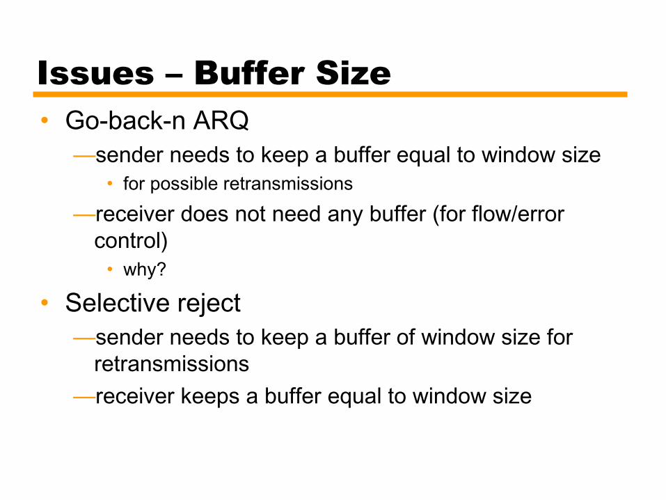
Issues – Buffer Size• Go-back-n ARQ
—sender needs to keep a buffer equal to window size• for possible retransmissions
—receiver does not need any buffer (for flow/error control)
• why?
• Selective reject—sender needs to keep a buffer of window size for
retransmissions—receiver keeps a buffer equal to window size
Issues - Performance• Notes on board• Appendix at the end of Chapter 14
—selective reject ARQ is not in the book
High Level Data Link Control• HDLC• ISO Standard• Basis for some other DLL protocols

HDLC Station Types• Primary station
—Controls operation of link—Frames issued are called commands
• Secondary station—Under control of primary station—Frames issued called responses
• Combined station—May issue commands and responses

HDLC Link Configurations• Unbalanced
—One primary and one or more secondary stations—Supports full duplex and half duplex
• Balanced—Two combined stations—Supports full duplex and half duplex
HDLC Transfer Modes (1)• Normal Response Mode (NRM)
—Unbalanced configuration—Primary initiates transfer to secondary—Secondary may only transmit data in response to
command from primary—Terminal-host communication
• Host computer as primary• Terminals as secondary
—not so common nowadays

HDLC Transfer Modes (2)• Asynchronous Balanced Mode (ABM)
—Balanced configuration—Either station may initiate transmission without
receiving permission—Most widely used

Frame Structure• All transmissions in frames• Single frame format for all data and control
exchanges

Frame Structure Diagram
Flag Fields• Delimit frame at both ends• 01111110• Receiver hunts for flag sequence to synchronize• Bit stuffing used to avoid confusion with data
containing 01111110—0 inserted after every sequence of five 1s—If receiver detects five 1s it checks next bit
• If 0, it is deleted• If 1 and seventh bit is 0, accept as flag
—If sixth and seventh bits 1, sender is indicating abort
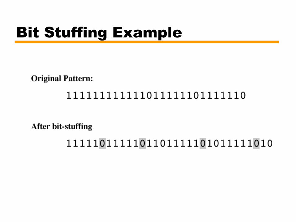
Bit Stuffing Example
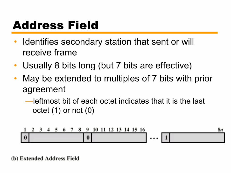
Address Field• Identifies secondary station that sent or will
receive frame• Usually 8 bits long (but 7 bits are effective)• May be extended to multiples of 7 bits with prior
agreement —leftmost bit of each octet indicates that it is the last
octet (1) or not (0)

Frame Types• Information - data to be transmitted to user
—Acknowledgment is piggybacked on information frames (only positive acknowledgment)
• Supervisory – ARQ messages (RR/RNR/REJ/SREJ) when piggyback not used (actually only RR can be piggybacked; for the other, we need Supervisory frames)
• Unnumbered – supplementary link control functions. For examples,—setting the modes—disconnect
• Control field is different for each frame type

Control Field Diagram
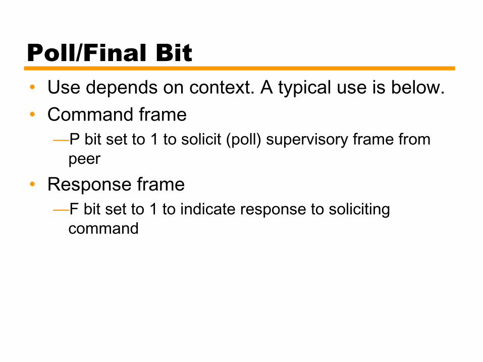
Poll/Final Bit• Use depends on context. A typical use is below.• Command frame
—P bit set to 1 to solicit (poll) supervisory frame from peer
• Response frame—F bit set to 1 to indicate response to soliciting
command

Information Field• Only in information and some unnumbered
frames• Must contain integral number of octets• Variable length

Frame Check Sequence Field• FCS• Error detection• 16 bit CRC• Optional 32 bit CRC

HDLC Operation• Exchange of information, supervisory and
unnumbered frames• Three phases
—Initialization—Data transfer—Disconnect

Initialization• Issue one of six set-mode commands
—Signals other side that initialization is requested—Specifies mode (NRM, ABM, ARM)—Specifies 3- or 7-bit sequence numbers
• If request accepted HDLC module on other side transmits "unnumbered acknowledged" (UA) frame
• If request rejected, "disconnected mode" (DM) sent
• All sent as unnumbered frames

Data Transfer• Both sides may begin to send user data in I-frames
— N(S): sequence number of outgoing I-frames• modulo 8 or 128, (3- or 7-bit)
— N(R) acknowledgment for I-frames received• seq. number of I-frame expected next
• S-frames are also used for flow and error control— Receive ready (RR) frame acknowledges last I-frame received
• Indicating next I-frame expected• Used when there is no reverse data
— Receive not ready (RNR) acknowledges, but also asks peer to suspend transmission of I-frames
• When ready, send RR to restart— REJ initiates go-back-N ARQ
• Indicates last I-frame received has been rejected• Retransmission is requested beginning with N(R)
— Selective reject (SREJ) requests retransmission of single frame

Disconnect• Send disconnect (DISC) frame• Remote entity must accept by replying with UA
—Informs layer 3 user about the termination of connection

Examples of Operation (1)
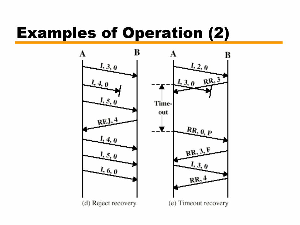
Examples of Operation (2)

Other DLC Protocols (LAPB,LAPD)• Link Access Procedure, Balanced (LAPB)
—Part of X.25 (ITU-T)—Subset of HDLC - ABM (Async. Balanced Mode)—Point to point link between user and packet switching
network node—HDLC frame format
• Link Access Procedure, D-Channel (LAPD)—Part of ISDN (ITU-T)—ABM—Always 7-bit sequence numbers (no 3-bit)—always 16-bit CRC—16-bit address field

Other DLC Protocols (LLC)• Logical Link Control (LLC)
—IEEE 802—For LANs (Local Area Networks)—Link control split between medium access control layer (MAC)
and LLC (on top of MAC)—Different frame format
• Two addresses needed (sender and receiver) – actually at MAC layer• Sender and receiver SAP addresses• Control field is same as HDLC (16-bit version for I and S frames; 8-bit
for U frames)—No primary and secondary - all stations are peers—Error detection at MAC layer
• 32 bit CRC

Other DLC Protocols (LLC)• LLC Services
—3 alternatives—Connection Mode Services
• Similar to HDLC ABM
—Unacknowledged connectionless services• no connection setup• No flow-control, no error control, no acks (thus not reliable)• good to be used with TCP/IP. Why?
—Acknowledged Connectionless Service• No connection setup• reliable communication