131469917 fortinet webui handbook 8 3
TRANSCRIPT

FortiBalancer 8.3
WebUI Handbook
©2012 Fortinet, Inc.
All Rights Reserved. II
Copyright Statement
Copyright©2000- 2012 Fortinet, Inc., 1090 Kifer Road Sunnyvale, CA 94086 , USA. All rights reserved.
This document is protected by copyright and distributed under licenses restricting its use, copying, distribution, and compilation. No part of this document may be reproduced in any form by any
means without prior written authorization of Fortinet, Inc.
Documentation is provided “as is” without warranty of any kind, either express or implied, including any kind of implied or express warranty of non - infringement or the implied warranties of
merchantability or fitness for a particular purpose. Fortinet, Inc., reserves the right to change any products described herein at any time, and without notice. Fortinet, Inc. assumes no
responsibility or liability arising from the use of products described herein, except as expressly agreed to in writing by Fortinet, Inc. The use and purchase of this product does not convey a
license to any patent copyright, or trademark rights, or any other intellectual property rights of Fortinet, Inc.
Warning: Modifications made to the Fortinet unit, unless expressly approved by Fortinet, Inc., could void the user’s authority to operate the equipment.
Declaration of Conformity
We, Fortinet, Inc., 1090 Kifer Road Sunnyvale, CA 94086; declare under our sole responsibility that the product(s) Fortinet, Inc., FortiBalancer appliance complies with Part 15 of FCC Rules.
Operation is subject to the following two conditions: (1) this device may not cause harmful interference, and (2) this device must accept any interference received, including interference that
may cause undesired operation.
Warning : This is a Class A digital device, pursuan t to Part 15 of the FCC rules. These limit s are designed to provide reasonable protection against harmful interference when the
equipment is operate d in a commercial environment. This equipment generates, uses, and can radiate radio frequency energy, and if not installed and used in accordance wit h the
instruction manual, may cause harmful interfe rence to radio communications. In a residential area, operation of this equipment is likely to cause harmful interference in which
case the user may be required to take adequate measures or product. In a d omestic environment this product may cause radio interference in which case the user may be required to
take adequate measures
.

©2012 Fortinet, Inc.
All Rights Reserved. III
About Fortinet
Fortinet Inc. is a worldwide provider of network security appliances and a market leader in unified threat management (UTM). Our products and subscription services provide broad, integrated
and high-performance protection against dynamic security threats while simplifying the IT security infrastructure. Our customers include enterprises, service providers and government entities
worldwide, including the majority of the 2009 Fortune Global 100. Fortinet’s broad product line goes beyond UTM to help secure the extended enterprise - from endpoints, to the perimeter and
the core, including databases and applications. Fortinet is headquartered in Sunnyvale, Calif., with offices around the world.
Contacting Fortinet
Please use the following information to contact us at Fortinet:
Website: http://www.fortinet.com
Telephone: Please go to https://support.fortinet.com
E-mail: Please go to https://support.fortinet.com
Address: Fortinet, Inc.
1090 Kifer Road
Sunnyvale
CA 94086

©2012 Fortinet, Inc.
All Rights Reserved. IV
Table of Contents
Copyright Statement ................................................................................................................ II
Declaration of Conformity ....................................................................................................... II
About Fortinet ........................................................................................................................ III
Contacting Fortinet ................................................................................................................ III
Table of Contents ................................................................................................................... IV
Web User Interface Introduction.............................................................................................. 1
Enabling the WebUI Function ................................................................................................. 2
Connecting to the FortiBalancer appliance ...................................................................... 2
Enabling the WebUI Function via CLI ............................................................................ 2
Using the WebUI Function ...................................................................................................... 4
Supported Browsers ......................................................................................................... 4
Accessing the WebUI ...................................................................................................... 5
Logging in the FortiBalancer WebUI .............................................................................. 6
Understanding the FortiBalancer WebUI ................................................................................. 7
Top Bar ............................................................................................................................ 8
Side Bar ........................................................................................................................... 9
Configuration Window .................................................................................................. 10
Using the FortiBalancer WebUI..................................................................................... 11
Configuring with the WebUI.................................................................................................. 12
Home Page ..................................................................................................................... 13
Basic Information ................................................................................................... 13
Flight Deck ............................................................................................................. 14
Quick Starts ............................................................................................................ 15
System Configuration............................................................................................................. 18
General Settings ............................................................................................................. 18
Host Settings .......................................................................................................... 18
Date/Time ............................................................................................................... 18
NTP ........................................................................................................................ 19
Basic Networking ........................................................................................................... 20
Interface ................................................................................................................. 20
ARP ........................................................................................................................ 25
Routing ................................................................................................................... 26
Name Resolution Host............................................................................................ 34
DNS ........................................................................................................................ 35
Switch..................................................................................................................... 35
Advanced Networking.................................................................................................... 36

©2012 Fortinet, Inc.
All Rights Reserved. V
NAT ....................................................................................................................... 36
IPv6 ........................................................................................................................ 38
IP Region ............................................................................................................... 41
IP Pool ................................................................................................................... 42
Port Forwarding ..................................................................................................... 43
High Availability ........................................................................................................... 45
Clustering ............................................................................................................... 45
HA ......................................................................................................................... 50
WebWall ........................................................................................................................ 58
Access Control ....................................................................................................... 58
Attacking Packet Filter........................................................................................... 60
Monitoring ..................................................................................................................... 61
Interface Statistics .................................................................................................. 61
NAT Translation Tables ......................................................................................... 62
Server Load Balance .............................................................................................................. 63
Real Services ................................................................................................................. 63
Real Services .......................................................................................................... 64
Health Check Setting ............................................................................................. 67
Virtual Services.............................................................................................................. 69
Virtual Services ...................................................................................................... 70
All Policy Statistics ................................................................................................ 83
Policy Order Templates .......................................................................................... 83
Virtual Service Global Setting ................................................................................ 84
Check Lists ..................................................................................................................... 85
Health Checker ....................................................................................................... 85
Health List .............................................................................................................. 86
Health Imports ........................................................................................................ 87
Groups ............................................................................................................................ 89
Groups .................................................................................................................... 90
Groups Setting ........................................................................................................ 93
Application Setting ......................................................................................................... 94
SIP NAT ................................................................................................................. 94
Direct Forward ....................................................................................................... 95
Monitoring ..................................................................................................................... 96
Status ...................................................................................................................... 96
Virtual Service Statistics ........................................................................................ 97
Group Statistics ...................................................................................................... 97
Real Service Statistics ............................................................................................ 97
Summary ................................................................................................................ 98
Report ..................................................................................................................... 99
Proxy .................................................................................................................................... 100
Compression................................................................................................................. 100

©2012 Fortinet, Inc.
All Rights Reserved. VI
Setting .................................................................................................................. 100
Type ..................................................................................................................... 101
Statistics ............................................................................................................... 102
Caching Proxy ............................................................................................................. 103
Global URL Filter ................................................................................................ 103
HTTP Settings ...................................................................................................... 105
Content Rewrite ................................................................................................... 109
Cache Settings ...................................................................................................... 116
DNS Cache Settings ............................................................................................. 119
SSL .............................................................................................................................. 120
Global Settings ..................................................................................................... 120
Global CRL .......................................................................................................... 123
Virtual Hosts ........................................................................................................ 124
Real Hosts ............................................................................................................ 134
SSL Errors............................................................................................................ 139
Monitoring ................................................................................................................... 140
Cache ................................................................................................................... 140
Advanced Load Balance ...................................................................................................... 141
InBound Settings .................................................................................................. 142
OutBound Settings ............................................................................................... 143
Statistics ............................................................................................................... 145
Report ................................................................................................................... 147
Global Load Balance .................................................................................................... 148
General Settings ................................................................................................... 149
Records................................................................................................................. 150
Topology .............................................................................................................. 154
Methods ................................................................................................................ 159
Bandwidth ............................................................................................................ 164
DPS ...................................................................................................................... 166
IANA .................................................................................................................... 170
Statistics ............................................................................................................... 171
Report ................................................................................................................... 172
Monitoring ................................................................................................................... 173
SDNS ................................................................................................................... 173
Pool SNMP Statistics ........................................................................................... 173
Admin Tools ........................................................................................................................ 174
System Management .................................................................................................... 174
System Info .......................................................................................................... 174
Access Control ..................................................................................................... 176
Update .................................................................................................................. 177
Shutdown/Reboot ................................................................................................. 178
License ................................................................................................................. 178

©2012 Fortinet, Inc.
All Rights Reserved. VII
Config Management .................................................................................................... 179
View ..................................................................................................................... 179
Backup ................................................................................................................. 180
Load ..................................................................................................................... 181
Clear ..................................................................................................................... 182
Synchronization ................................................................................................... 183
Synchronization Sdns ........................................................................................... 186
Command Timeout .............................................................................................. 187
Graph ........................................................................................................................... 188
Logging ................................................................................................................ 188
SNMP .................................................................................................................. 192
Statistics ............................................................................................................... 195
Graph Monitoring ................................................................................................ 197
Troubleshooting ........................................................................................................... 201
Tools .................................................................................................................... 201
Debug Monitor ..................................................................................................... 203
SLB Server ........................................................................................................... 204
Support Access .................................................................................................... 205
User Management ........................................................................................................ 206
User Management ................................................................................................ 206
QoS Configuration ............................................................................................................... 207
QoS .............................................................................................................................. 207
QoS Entries .......................................................................................................... 208
Interfaces .............................................................................................................. 209
Statistics ....................................................................................................................... 210
QoS Interface Statistics ................................................................................................ 210
©2012 Fortinet, Inc.
All Rights Reserved. 1
Web User Interface Introduction
The FortiBalancer Web User Interface (WebUI) is designed to maximize the functionality and performance of the FortiBalancer appliance by allowing administrators to configure
and control key functions of the FortiBalancer appliance. This WebUI Guide covers the functional elements of the graphical interface as well as basic setup steps.
This WebUI Guide is one of the three documentation resources available to administrators from Fortinet, Inc. The other two are the CLI Handbook and User Guide. The CLI
Handbook is a resource tool that instructs administrators on detailed CLI operations of the FortiBalancer appliance. The User Guide is a more in-depth configuration strategy
resource for complex FortiBalancer appliance deployments.
The three documents as well as current release notes and installation guides are available on the Documentation CD that accompanies the FortiBalancer appliance or from Fortinet
directly.

©2012 Fortinet, Inc.
All Rights Reserved. 2
Enabling the WebUI Function
Connecting to the FortiBalancer appliance
To use the WebUI function, first we should connect the client PC to the FortiBalancer appliance.
Put the FortiBalancer appliance onto the rack properly. Attach the power cord to the power supply, and turn on the power by pressing the power button.
Connect one end of the Console cable to the serial port of the client PC, and the other end to the serial port of the FortiBalancer appliance. Then, run the terminal software on the
client PC to access the FortiBalancer via the Console connection.
Enabling the WebUI Function via CLI
To access the FortiBalancer via the terminal software, please first make certain that your terminal software is set as follows:
Setting Value
Emulation VT 100
Baud 9600
Number of Bits 8
Parity No
Stop Bits 1
Flow Control No

©2012 Fortinet, Inc.
All Rights Reserved. 3
Enabling the WebUI Function via CLI (Continue)
After the above settings are finished, you can access the FortiBalancer CLI interface via the terminal software.
In the CLI interface, you will be first prompted for the user name and password (default to array and admin). Once you log in successfully, the FortiBalancer will show the prompt
“FortiBalancer>”. Enter the command “enable” to go to “Enable” mode, and the FortiBalancer will show “FortiBalancer#”. Continue to enter the command “configure terminal”
to go to “Config” mode, and the FortiBalancer will show “FortiBalancer(config)#”.
Then, execute the following commands to complete necessary network settings and enable the WebUI function:
Command Operation
ip address {system_ifname|mnet_ifname|vlan_ifname|bond_ifname}
<ip_address> <netmask>
This command is used to set the IP address and netmask of the system
interface, MNET interface, VLAN interface or bond interface.
webui ip <ip_address> This command is used to set the WebUI IP address.
ip route default <gateway_ip> This command is used to set the default gateway IP address.
webui {on|off} This command is used to enable or disable the WebUI function.
Example:
FortiBalancer>enable
FortiBalancer#config terminal
FortiBalancer(config)#ip address outside 10.3.70.100 255.255.255.0
FortiBalancer(config)#webui ip 10.3.70.100
FortiBalancer(config)#ip route default 10.10.0.1
FortiBalancer(config)#webui on
FortiBalancer(config)#exit

©2012 Fortinet, Inc.
All Rights Reserved. 4
Using the WebUI Function
Supported Browsers
The Array FortiBalancer WebUI supports the following browsers:
Microsoft Internet Explorer (Recommended)
Mozilla Firefox
Google Chrome
Note: It is highly recommended to use the Microsoft Internet Explorer (IE) browser for accessing the FortiBalancer WebUI. This handbook will introduce the WebUI operations in
the IE browser.
©2012 Fortinet, Inc.
All Rights Reserved. 5
Accessing the WebUI
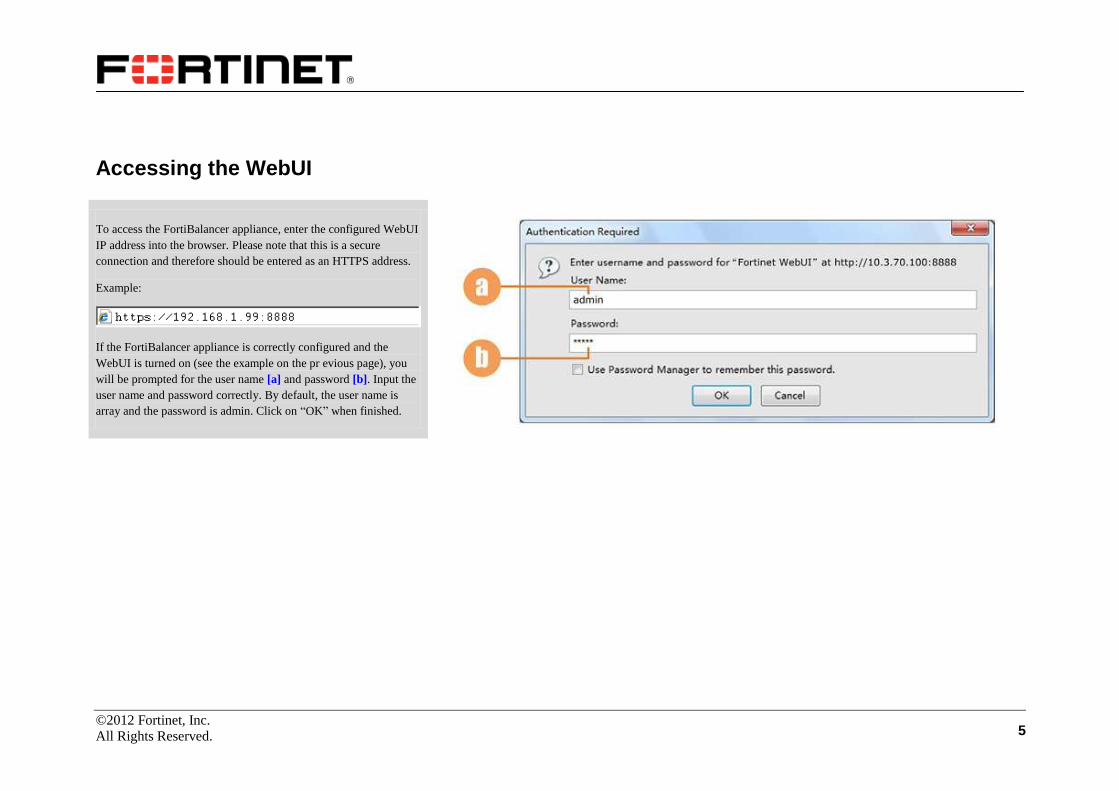
To access the FortiBalancer appliance, enter the configured WebUI
IP address into the browser. Please note that this is a secure
connection and therefore should be entered as an HTTPS address.
Example:
If the FortiBalancer appliance is correctly configured and the
WebUI is turned on (see the example on the pr evious page), you
will be prompted for the user name [a] and password [b]. Input the
user name and password correctly. By default, the user name is
array and the password is admin. Click on “OK” when finished.

©2012 Fortinet, Inc.
All Rights Reserved. 6
Logging in the FortiBalancer WebUI
After the step of user registration, the FortiBalancer appliance will
prompt you for an Enable level password. Enter the enable
password correctly in the text field [a] (default to null), and click
on the “Login” button [b]. Then, you will be taken to the
FortiBalancer WebUI.
©2012 Fortinet, Inc.
All Rights Reserved. 7
Understanding the FortiBalancer WebUI
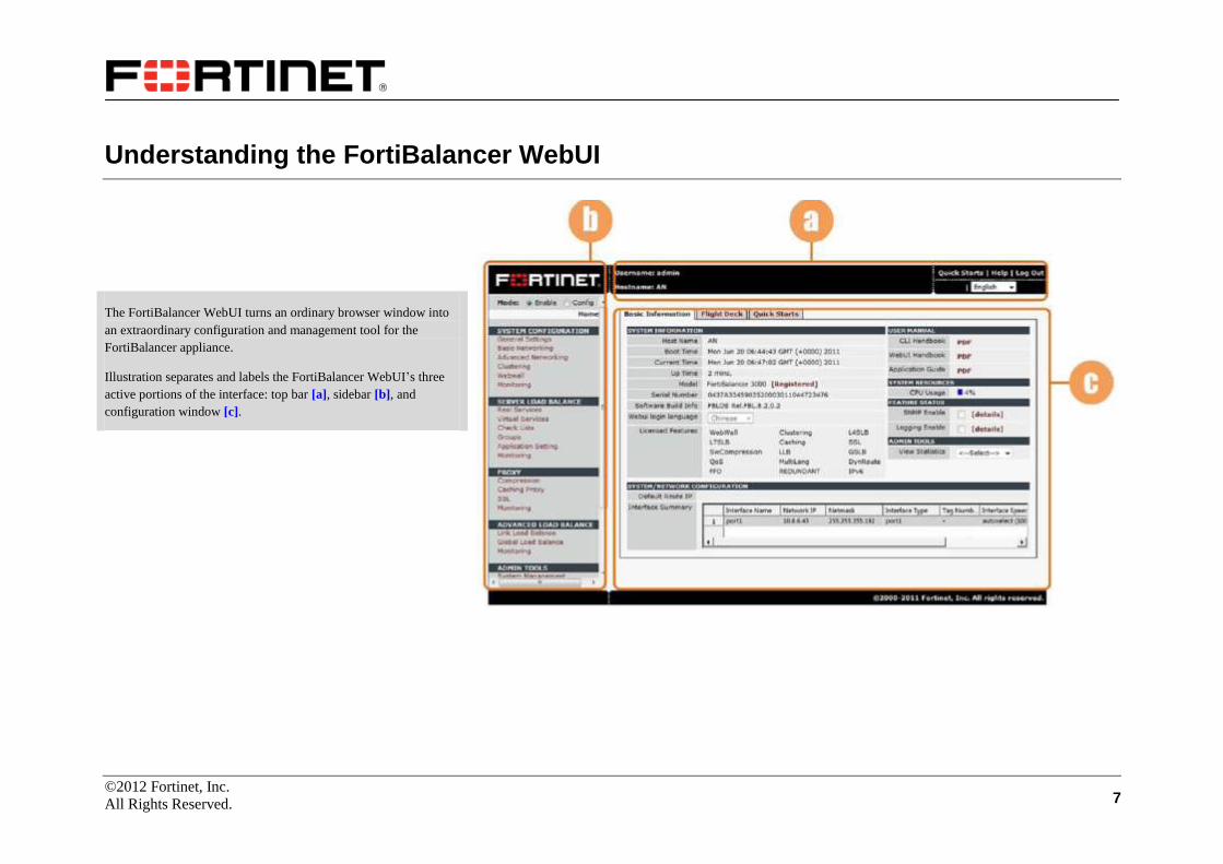
The FortiBalancer WebUI turns an ordinary browser window into
an extraordinary configuration and management tool for the
FortiBalancer appliance.
Illustration separates and labels the FortiBalancer WebUI’s three
active portions of the interface: top bar [a], sidebar [b], and
configuration window [c].

©2012 Fortinet, Inc.
All Rights Reserved. 8
Top Bar
The top bar displays basic static information such as user’s name
[a], FortiBalancer appliance host name [b] and four basic
hyperlinks: Quick Starts [c], Help [d], Log Out [e] and Save Config
[f]. Users can also set the WebUI display language via the selector
[g].

©2012 Fortinet, Inc.
All Rights Reserved. 9
Side Bar
The side bar serves as the principal navigational tool for the Web
interface. With this sidebar, administrators can perform desired
configuration management and general setup about the
FortiBalancer appliance.
Administrators can switch between the Enable and Config modes
via the radio buttons [h]. Features are presented in groups [i],
depending on site and user specifics as well as licensed features.
To configure a specific feature, click on the link, A white strip [j]
will indicate your location within each feature group.
©2012 Fortinet, Inc.
All Rights Reserved. 10
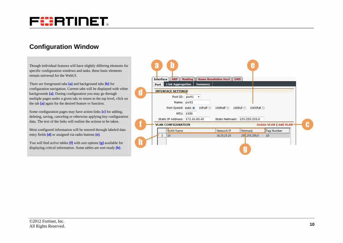
Configuration Window
Though individual features will have slightly differing elements for
specific configuration windows and tasks, these basic elements
remain universal for the WebUI.
There are foreground tabs [a] and background tabs [b] for
configuration navigation. Current tabs will be displayed with white
backgrounds [a]. During configuration you may go through
multiple pages under a given tab; to return to the top level, click on
the tab [a] again for the desired feature or function.
Some configuration pages may have action links [c] for adding,
deleting, saving, canceling or otherwise applying key configuration
data. The text of the links will outline the actions to be taken.
Most configured information will be entered through labeled data
entry fields [d] or assigned via radio buttons [e].
You will find active tables [f] with sort options [g] available for
displaying critical information. Some tables are sort-ready [h].

©2012 Fortinet, Inc.
All Rights Reserved. 11
Using the FortiBalancer WebUI
When you log into the WebUI, please note that you are first in the
Enable mode [a]. Also note the default username “array” and
default FortiBalancer appliance hostname “AN” are displayed [b]
within the top bar. Finally, notice that the feature link Home [c] is
right justified and framed with a white bar. Whenever a feature link
like General Settings [d] is selected, all related features in the
feature group [e] will become right justified with the selected
feature singled out with the white bar [d] and the previously
selected feature link [c] returns to the left side of the sidebar.
©2012 Fortinet, Inc.
All Rights Reserved. 12
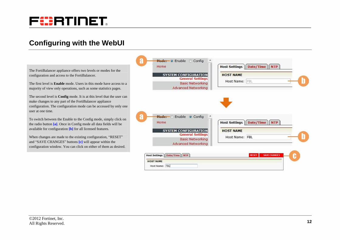
Configuring with the WebUI
The FortiBalancer appliance offers two levels or modes for the
configuration and access to the FortiBalancer.
The first level is Enable mode. Users in this mode have access to a
majority of view only operations, such as some statistics pages.
The second level is Config mode. It is at this level that the user can
make changes to any part of the FortiBalancer appliance
configuration. The configuration mode can be accessed by only one
user at one time.
To switch between the Enable to the Config mode, simply click on
the radio button [a]. Once in Config mode all data fields will be
available for configuration [b] for all licensed features.
When changes are made to the existing configuration, “RESET”
and “SAVE CHANGES” buttons [c] will appear within the
configuration window. You can click on either of them as desired.
©2012 Fortinet, Inc.
All Rights Reserved. 13
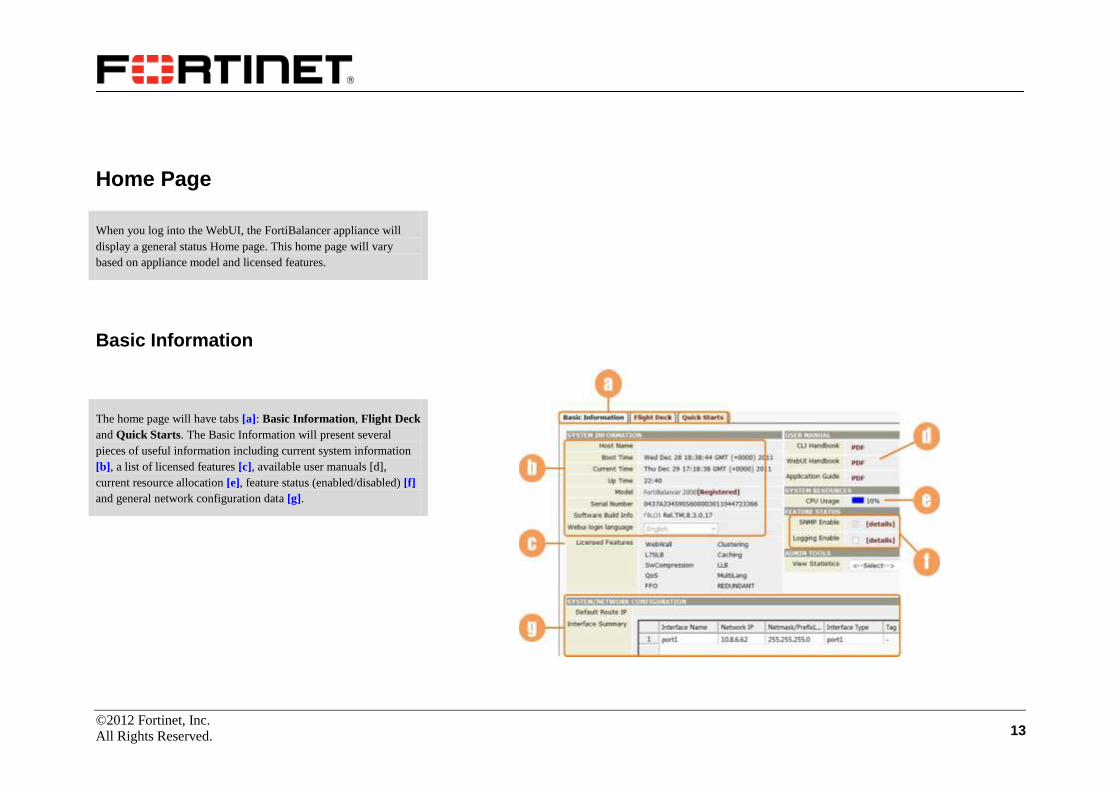
Home Page
When you log into the WebUI, the FortiBalancer appliance will
display a general status Home page. This home page will vary
based on appliance model and licensed features.
Basic Information
The home page will have tabs [a]: Basic Information, Flight Deck
and Quick Starts. The Basic Information will present several
pieces of useful information including current system information
[b], a list of licensed features [c], available user manuals [d],
current resource allocation [e], feature status (enabled/disabled) [f]
and general network configuration data [g].
©2012 Fortinet, Inc.
All Rights Reserved. 14
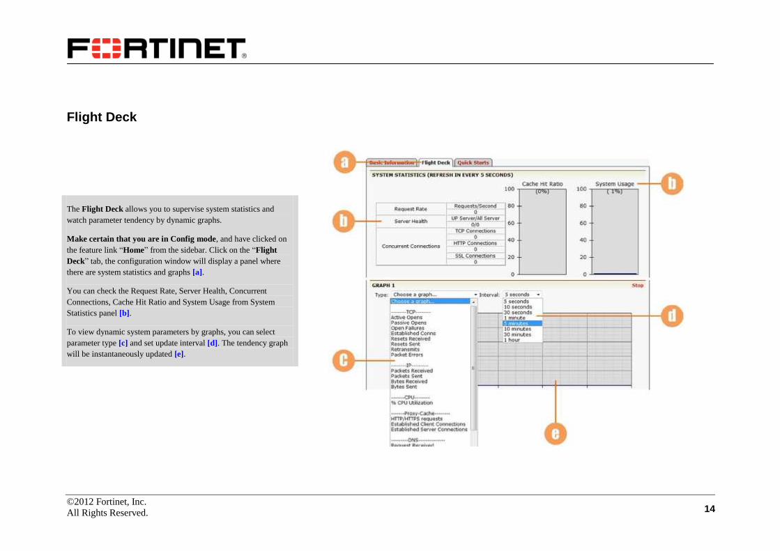
Flight Deck
The Flight Deck allows you to supervise system statistics and
watch parameter tendency by dynamic graphs.
Make certain that you are in Config mode, and have clicked on
the feature link “Home” from the sidebar. Click on the “Flight
Deck” tab, the configuration window will display a panel where
there are system statistics and graphs [a].
You can check the Request Rate, Server Health, Concurrent
Connections, Cache Hit Ratio and System Usage from System
Statistics panel [b].
To view dynamic system parameters by graphs, you can select
parameter type [c] and set update interval [d]. The tendency graph
will be instantaneously updated [e].

©2012 Fortinet, Inc.
All Rights Reserved. 15
Quick Starts
In order to make the total configuration easier and more convenient
for FortiBalancer appliance users, we set up “Quick Starts” to
guide users to directly complete desired configurations.
To perform quick start configuration, make certain that you are
in Config mode and have selected the tab “Quick Starts” [a].
Select the “Basic Quick Start” module from the selector [b], and
the configuration window will present 6 steps to carry out basic
configurations [c].
You may notice the action links are in two colors in the
configuration page. The red ones represent the steps that have
already been finished, while the green ones indicate you have not
configured them yet. Click on the action links according to the
numbers of collective steps.
Next, we will take Basic Quick Start as an example to illustrate
the operation steps of quick starts.

©2012 Fortinet, Inc.
All Rights Reserved. 16
Quick Starts (Continue)
Basic Quick Start:
Click on the action link “1. Modify host settings”, WebUI will
guide you to the Host Settings configuration page [a]. Fill in the
blank with host name [b], click on the button “Save Changes” [c],
and then click on the action link “Quick Starts” on the upper right
side [d], the configuration window will return to the Quick Starts
panel (see the former page).
Click on the action link “2. Modify date/time”. For details about
configuring this page [e], please refer to the “General Settings”
section in the “System Configuration” chapter.
After configuring the Date/Time, click on “Quick Starts” [f] to go
back to the Quick Starts main panel in order to perform further
tasks.
“3. Add interface ip”, “4. Add default route”, “5. Add static route”
and “6. Add dns” action links are all from System
Configuration/Basic Networking. Remember to click on the action
link “Quick Starts” if you have finished one step and want to move
on to another.
©2012 Fortinet, Inc.
All Rights Reserved. 17
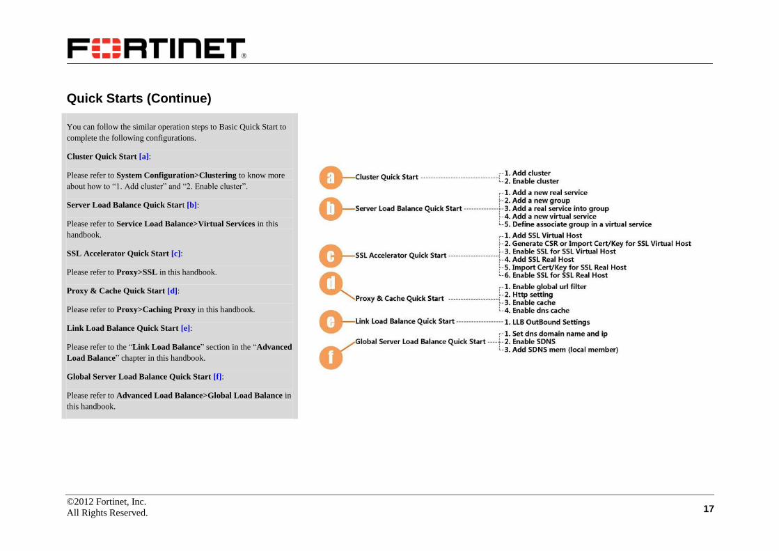
Quick Starts (Continue)
You can follow the similar operation steps to Basic Quick Start to
complete the following configurations.
Cluster Quick Start [a]:
Please refer to System Configuration>Clustering to know more
about how to “1. Add cluster” and “2. Enable cluster”.
Server Load Balance Quick Start [b]:
Please refer to Service Load Balance>Virtual Services in this
handbook.
SSL Accelerator Quick Start [c]:
Please refer to Proxy>SSL in this handbook.
Proxy & Cache Quick Start [d]:
Please refer to Proxy>Caching Proxy in this handbook.
Link Load Balance Quick Start [e]:
Please refer to the “Link Load Balance” section in the “Advanced
Load Balance” chapter in this handbook.
Global Server Load Balance Quick Start [f]:
Please refer to Advanced Load Balance>Global Load Balance in
this handbook.

©2012 Fortinet, Inc.
All Rights Reserved. 18
System Configuration
General Settings
Host Settings
Make certain you are in Config mode, click “General Settings”
[a].
On the “Host Settings” page [b], enter the host name for the
FortiBalancer appliance [c], and click on the “SAVE CHANGES”
button [d] to save your settings.
Date/Time
Click on the “Date/Time” tab [e]. Enter the date and time as
desired [f], and click on “SAVE CHANGES” [g]. The
FortiBalancer appliance has the default time zone set to GMT [h].
To change this time zone, un-select the time zone box, and
configure the time zone properly via the three selectors [i]. Then,
remember to click on the “SAVE CHANGES” button [g].

©2012 Fortinet, Inc.
All Rights Reserved. 19
NTP
Click on the “NTP” tab [a]. You can enable NTP by selecting the
check box [b]. (Remember to save your setting [c].) Before you
enable NTP, you need to first add an NTP Server. Click on the
action link “Add” [d], supply the IP address and version number of
the NTP server [e]. Click on the action link “Save” [f]. The newly
added server will be displayed in the sort ready table [g].
With the NTP function enabled, you can view the NTP statistics in
the box [h].

©2012 Fortinet, Inc.
All Rights Reserved. 20
Basic Networking
Make certain you are in Config mode and click “Basic
Networking” [a].
Interface
To complete the interface settings, select the tab “Interface” and its
sub tab “Port” [b].
Port
To perform interface settings, select port ID via the selector [c],
supply its name [d], set the port speed via the radio buttons [e],
supply the MTU value [f] and supply the static IPv4/IPv6 address
and static netmask/prefix length in text fields [g] and [h]. Besides,
you can change the MAC address of the system interface [i].
After confirming the input information, click on the “SAVE
CHANGES” button [j] to save your settings.
©2012 Fortinet, Inc.
All Rights Reserved. 21
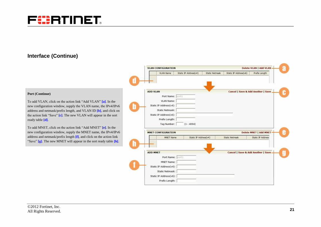
Interface (Continue)
Port (Continue)
To add VLAN, click on the action link “Add VLAN” [a]. In the
new configuration window, supply the VLAN name, the IPv4/IPv6
address and netmask/prefix length, and VLAN ID [b], and click on
the action link “Save” [c]. The new VLAN will appear in the sort
ready table [d].
To add MNET, click on the action link “Add MNET” [e]. In the
new configuration window, supply the MNET name, the IPv4/IPv6
address and netmask/prefix length [f], and click on the action link
“Save” [g]. The new MNET will appear in the sort ready table [h].
©2012 Fortinet, Inc.
All Rights Reserved. 22
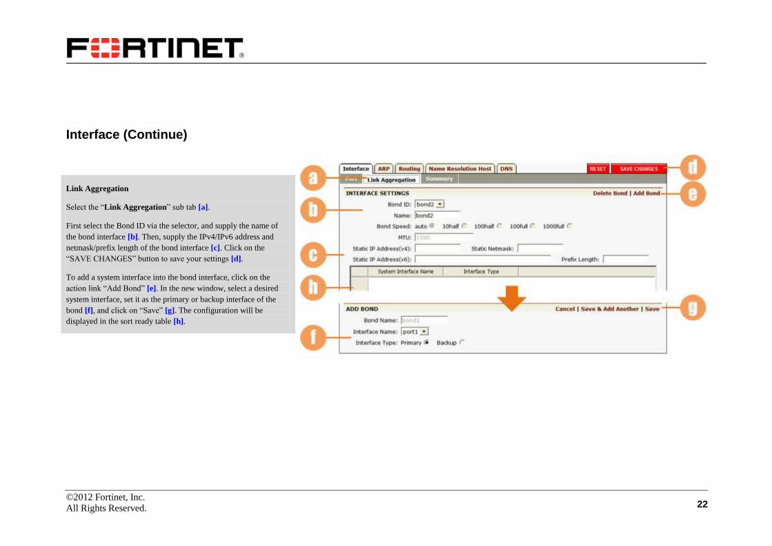
Interface (Continue)
Link Aggregation
Select the “Link Aggregation” sub tab [a].
First select the Bond ID via the selector, and supply the name of
the bond interface [b]. Then, supply the IPv4/IPv6 address and
netmask/prefix length of the bond interface [c]. Click on the
“SAVE CHANGES” button to save your settings [d].
To add a system interface into the bond interface, click on the
action link “Add Bond” [e]. In the new window, select a desired
system interface, set it as the primary or backup interface of the
bond [f], and click on “Save” [g]. The configuration will be
displayed in the sort ready table [h].

©2012 Fortinet, Inc.
All Rights Reserved. 23
Interface (Continue)
Link Aggregation (Continue)
The FortiBalancer appliance supports configuring MNET or VLAN
on bond interface. The bond interface configuration must be
performed before configuring MNET/VLAN on it.
To add VLAN, click on the action link “Add VLAN” [a]. In the
new window, supply the VLAN name, IPv4/IPv6 address and
netmask/prefix length, and VLAN ID [b], and click on “Save” [c].
The new VLAN will appear in the sort ready table [d].
To add MNET, click on the action link “Add MNET” [e]. In the
new window, supply the MNET name, IPv4/IPv6 address and
netmask/prefix length [f], and click on “Save” [g]. The new MNET
will appear in the sort ready table [h].
©2012 Fortinet, Inc.
All Rights Reserved. 24
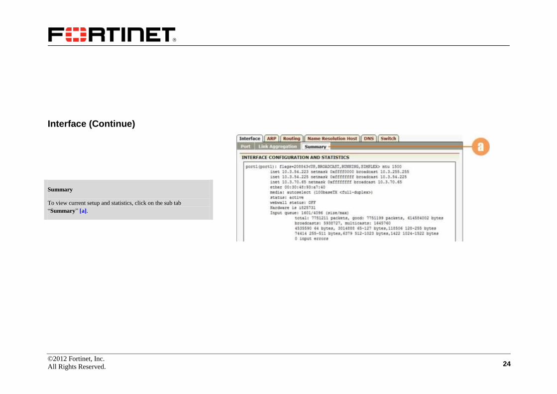
Interface (Continue)
Summary
To view current setup and statistics, click on the sub tab
“Summary” [a].

©2012 Fortinet, Inc.
All Rights Reserved. 25
ARP
Extreme care should be taken when altering the ARP table.
Administrators should not clear ARP entries for IP addresses that
are already assigned to establish.
Click on the “ARP” tab [a] and the main window will display an
ARP table.
The table contains sort-ready columns [b]. To add an ARP table
entry, click on the “Add ARP” action link [c]. A new configuration
window will appear.
Enter appropriate IP and hardware address in the data fields [d].
Click on the desired action link [e].
To remove an ARP entry, select the desired entry form the
displayed list [f] and click on “Delete ARP” action link [g]. A new
window will appear, click “OK” to delete ARP entry, click
“cancel” to keep the ARP entry.

©2012 Fortinet, Inc.
All Rights Reserved. 26
Routing
Make certain you are in Config mode and have selected the
“Routing” tab [a]. Seven sub tabs are displayed [b].
Default Routes
Verify and/or change the default route. To add a global default
route, click on the action link [c] and the configuration window
will present a configuration field for the route.
Supply the destination IP (IPv4 or IPv6 address) in the field [d].
Click on the desired action link [e] to continue. The configured
route IP address will be displayed in the table [f].
To remove a global default route, simply select it from the
displayed list and click on the “Delete Global Default Route”
action link [g].
©2012 Fortinet, Inc.
All Rights Reserved. 27
Routing (Continue)
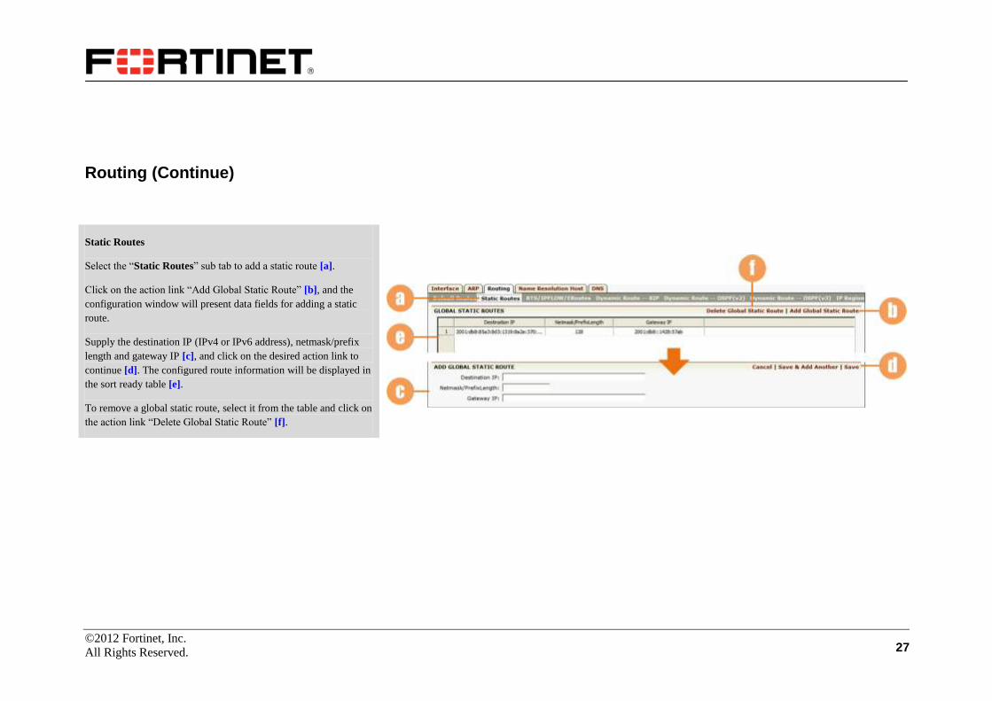
Static Routes
Select the “Static Routes” sub tab to add a static route [a].
Click on the action link “Add Global Static Route” [b], and the
configuration window will present data fields for adding a static
route.
Supply the destination IP (IPv4 or IPv6 address), netmask/prefix
length and gateway IP [c], and click on the desired action link to
continue [d]. The configured route information will be displayed in
the sort ready table [e].
To remove a global static route, select it from the table and click on
the action link “Delete Global Static Route” [f].
©2012 Fortinet, Inc.
All Rights Reserved. 28
Routing (Continue)
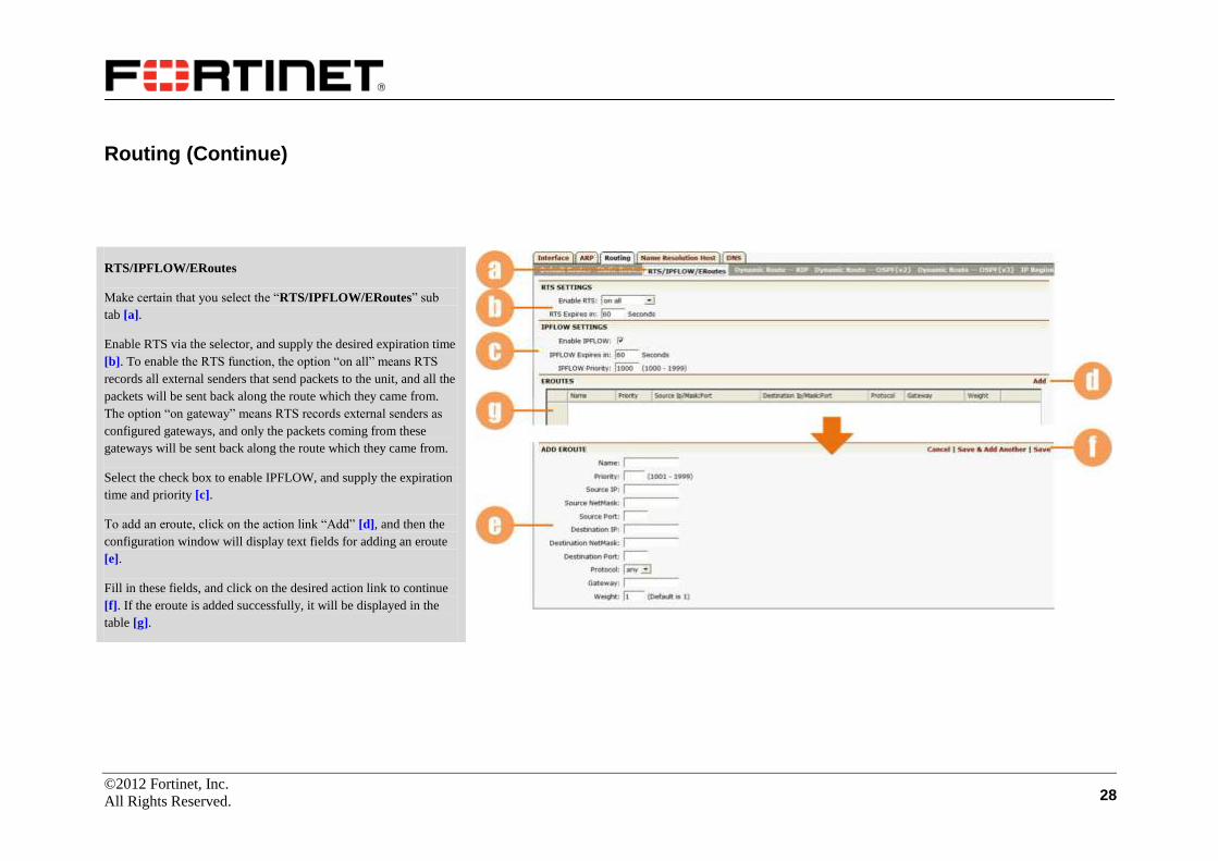
RTS/IPFLOW/ERoutes
Make certain that you select the “RTS/IPFLOW/ERoutes” sub
tab [a].
Enable RTS via the selector, and supply the desired expiration time
[b]. To enable the RTS function, the option “on all” means RTS
records all external senders that send packets to the unit, and all the
packets will be sent back along the route which they came from.
The option “on gateway” means RTS records external senders as
configured gateways, and only the packets coming from these
gateways will be sent back along the route which they came from.
Select the check box to enable IPFLOW, and supply the expiration
time and priority [c].
To add an eroute, click on the action link “Add” [d], and then the
configuration window will display text fields for adding an eroute
[e].
Fill in these fields, and click on the desired action link to continue
[f]. If the eroute is added successfully, it will be displayed in the
table [g].
©2012 Fortinet, Inc.
All Rights Reserved. 29
Routing (Continue)
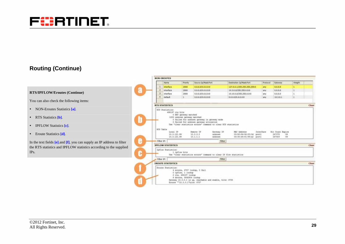
RTS/IPFLOW/Eroutes (Continue)
You can also check the following items:
NON-Eroutes Statistics [a].
RTS Statistics [b].
IPFLOW Statistics [c].
Eroute Statistics [d].
In the text fields [e].and [f], you can supply an IP address to filter
the RTS statistics and IPFLOW statistics according to the supplied
IPs.

©2012 Fortinet, Inc.
All Rights Reserved. 30
Routing (Continue)
Dynamic Route--RIP
Select the “Dynamic Route--RIP” sub tab [a]. You can enable RIP
by selecting the check box [b]. If you enable the RIP, you need to
further specify the version of RIP via the selector [c]. Then, click
on “SAVE CHANGES” button [d] when it appears.
Click on the action link “Add” [e] and a new configuration page
will be presented. Supply the destination IP address and netmask
[f] properly and click on the “Save” action link [g]. Then, the
added information will be displayed in the table [h]. You can clear
RIP settings by clicking on the “Clear” button [i].
After you set the RIP network properly, the information of the
routes dynamically detected will be displayed in the table [j].

©2012 Fortinet, Inc.
All Rights Reserved. 31
Routing (Continue)
Dynamic Route—OSPFv2
Select the “Dynamic Route—OSPFv2” sub tab [a]. You can
enable OSPF by selecting the check box [b]. Then, click on “SAVE
CHANGES” button [c] when it appears.
Click on the action link “Add” [d] and a new configuration page
will be presented. Supply the destination IP address, netmask and
area ID [e] properly and click on the “Save” action link [f]. Then,
the added information will be displayed in the table [g]. You can
clear OSPF settings by clicking on the “Clear” button [h].
After you set the OSPF network properly, the information of the
routes dynamically detected will be displayed in the table [i].
©2012 Fortinet, Inc.
All Rights Reserved. 32
Routing (Continue)
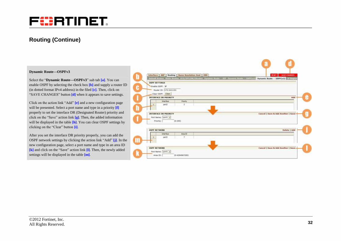
Dynamic Route—OSPFv3
Select the “Dynamic Route—OSPFv3” sub tab [a]. You can
enable OSPF by selecting the check box [b] and supply a router ID
(in dotted format IPv4 address) in the filed [c]. Then, click on
“SAVE CHANGES” button [d] when it appears to save settings.
Click on the action link “Add” [e] and a new configuration page
will be presented. Select a port name and type in a priority [f]
properly to set the interface DR (Designated Router) priority and
click on the “Save” action link [g]. Then, the added information
will be displayed in the table [h]. You can clear OSPF settings by
clicking on the “Clear” button [i].
After you set the interface DR priority properly, you can add the
OSPF network settings by clicking the action link “Add” [j]. In the
new configuration page, select a port name and type in an area ID
[k] and click on the “Save” action link [l]. Then, the newly added
settings will be displayed in the table [m].
©2012 Fortinet, Inc.
All Rights Reserved. 33
Routing (Continue)
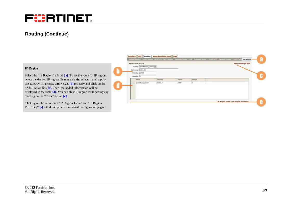
IP Region
Select the “IP Region” sub tab [a]. To set the route for IP region,
select the desired IP region file name via the selector, and supply
the gateway IP, priority and weight [b] properly and click on the
“Add” action link [c]. Then, the added information will be
displayed in the table [d]. You can clear IP region route settings by
clicking on the “Clear” button [c].
Clicking on the action link “IP Region Table” and “IP Region
Proximity” [e] will direct you to the related configuration pages.

©2012 Fortinet, Inc.
All Rights Reserved. 34
Name Resolution Host
Make certain you are in Config mode and have selected the
“Name Resolution Host” tab [a]. To add a new host, click on the
action link “Add Network Host” [b].
Within the supplied configuration window, supply the host name
and the host IP address in the text fields [c]. Once completed, click
the next desired action link [d].
All added hosts will be displayed in a sort enabled table [e] for
editing.
To delete a host, select the host name from the table [e] and click
on the desired action link [f]. A new window will appear, click
“OK” to delete the network host name, click “cancel” to keep the
network host name.

©2012 Fortinet, Inc.
All Rights Reserved. 35
DNS
Make certain you are in Config mode and have selected the
“DNS” tab [a].
From this configuration page, you may edit or assign DNS IP
addresses by clicking on the action links [b].
Enter DNS IP address in dotted IP format [d] and click on the
desired action link [e].
To delete a DNS, select the DNS address from the table [c] and
click on the desired action link [b]. A new window will appear,
click “OK” to delete ARP entry, click “cancel” to keep the ARP
entry.
Switch
For the model FortiBalancer 4600, users can further see the
“Switch” tab [g] under “Basic Networking”. Under this tab, users
can access the WebUI of AGS switch.
First, confirm the switch’s Web link displayed in the text box [h]
(if incorrect, input the correct link here), and then click on the
“Open Switch Web Admin” [i] action link to directly go to the
switch’s WebUI for further configuration. To read the switch user
manual, users can click on the action link [j] to open the manual.
©2012 Fortinet, Inc.
All Rights Reserved. 36
Advanced Networking
NAT
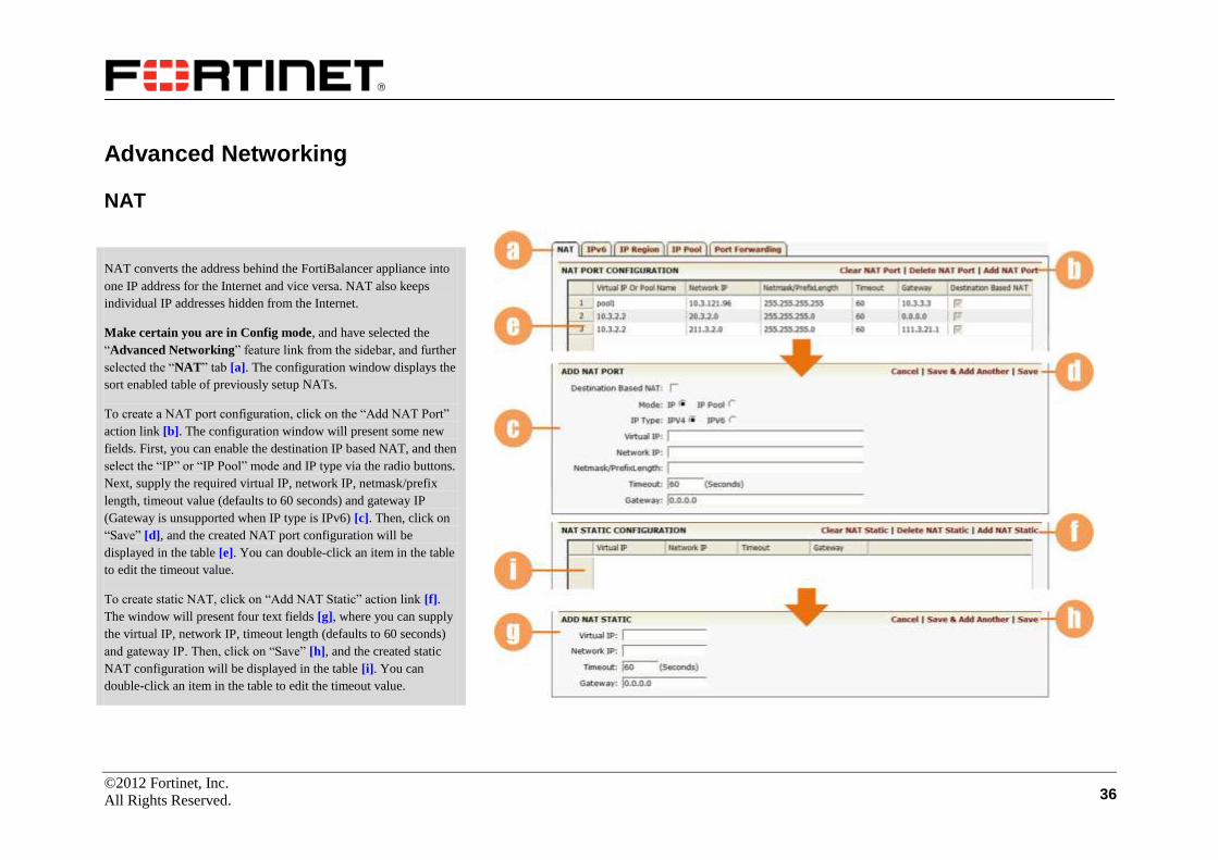
NAT converts the address behind the FortiBalancer appliance into
one IP address for the Internet and vice versa. NAT also keeps
individual IP addresses hidden from the Internet.
Make certain you are in Config mode, and have selected the
“Advanced Networking” feature link from the sidebar, and further
selected the “NAT” tab [a]. The configuration window displays the
sort enabled table of previously setup NATs.
To create a NAT port configuration, click on the “Add NAT Port”
action link [b]. The configuration window will present some new
fields. First, you can enable the destination IP based NAT, and then
select the “IP” or “IP Pool” mode and IP type via the radio buttons.
Next, supply the required virtual IP, network IP, netmask/prefix
length, timeout value (defaults to 60 seconds) and gateway IP
(Gateway is unsupported when IP type is IPv6) [c]. Then, click on
“Save” [d], and the created NAT port configuration will be
displayed in the table [e]. You can double-click an item in the table
to edit the timeout value.
To create static NAT, click on “Add NAT Static” action link [f].
The window will present four text fields [g], where you can supply
the virtual IP, network IP, timeout length (defaults to 60 seconds)
and gateway IP. Then, click on “Save” [h], and the created static
NAT configuration will be displayed in the table [i]. You can
double-click an item in the table to edit the timeout value.
©2012 Fortinet, Inc.
All Rights Reserved. 37
NAT (Continue)
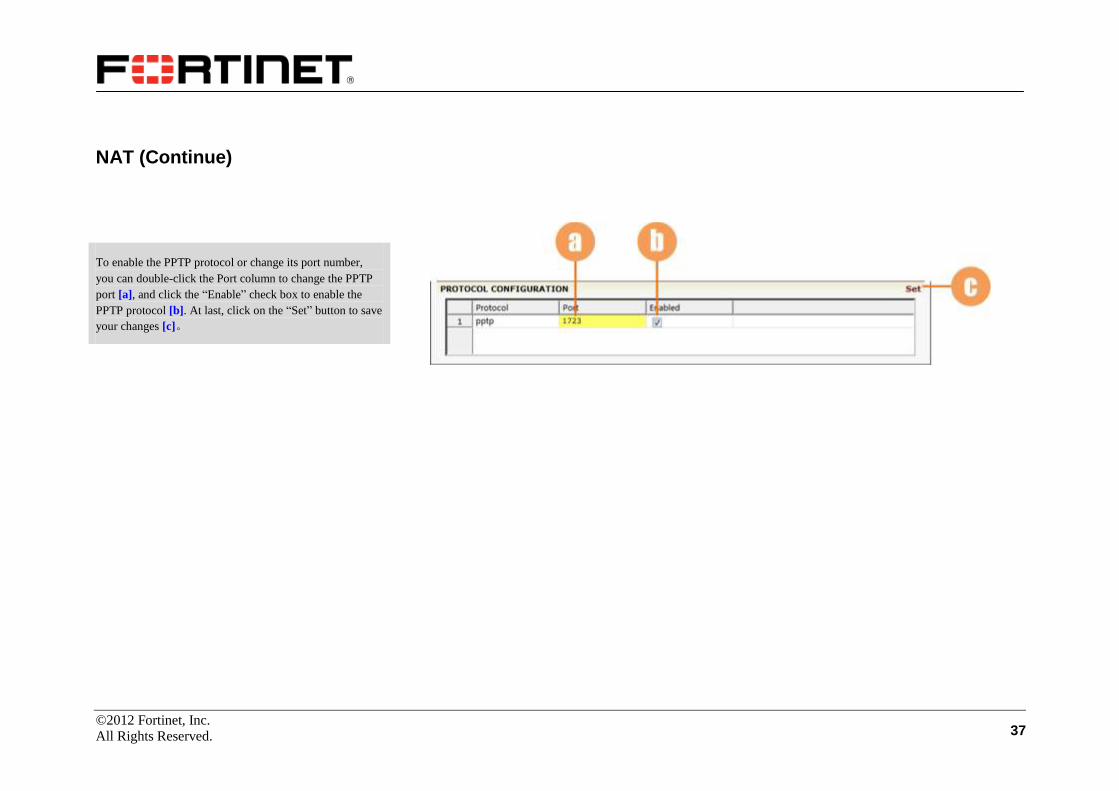
To enable the PPTP protocol or change its port number,
you can double-click the Port column to change the PPTP
port [a], and click the “Enable” check box to enable the
PPTP protocol [b]. At last, click on the “Set” button to save
your changes [c]。

©2012 Fortinet, Inc.
All Rights Reserved. 38
IPv6
Array IPv6 implementation includes two parts currently: IPv6
routing and NAT-PT (Network Address Translation-Protocol
Translation).
Select the “IPv6” tab [a], and the window displays the “Addresses”
sub tab by default [b].
Addresses
This page allows you to set the IPv6 addresses for system
interfaces. First, specify the interface name via the selector, and
further input the desired IPv6 address and prefix length in the text
fields [c].
Then, click on the “Set” action link [d]. The configuration will be
displayed in the sort ready table [e]. Note: Only one address can be
configured on each interface.
You can also click on the “Delete” action link to delete a
configuration item in the table or “Clear” to delete all the
configurations [d].

©2012 Fortinet, Inc.
All Rights Reserved. 39
IPv6 (Continue)
Routing
Select the “Routing” tab [a].
First, you can configure the default IPv6 gateway. Input the default
gateway address in the text field (should be a global unicast IPv6
address) [b], and click on the “Set” action link to save your
configuration [c].
Then, you can set the IPv6 static route. Input the destination
address, prefix length and gateway IP address (the destination
address and gateway address should be global unicast IPv6
addresses) in the text fields [d] and click on the “Add” action link
[e]. The configuration will be displayed in the sort ready table [f].
©2012 Fortinet, Inc.
All Rights Reserved. 40
IPv6 (Continue)
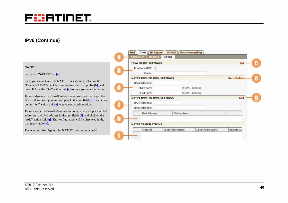
NATPT
Select the “NATPT” tab [a].
First, you can activate the NATPT translation by selecting the
“Enable NATPT” check box and setting the IPv6 prefix [b], and
then click on the “Set” action link [c] to save your configuration.
To set a dynamic IPv6-to-IPv4 translation rule, you can input the
IPv4 address, start port and end port in the text fields [d], and click
on the “Set” action link [e] to save your configuration.
To set a static IPv4-to-IPv6 translation rule, you can input the IPv4
addresses and IPv6 address in the text fields [f], and click on the
“Add” action link [g]. The configuration will be displayed in the
sort ready table [h].
The window also displays the NAT-PT translation table [i].
©2012 Fortinet, Inc.
All Rights Reserved. 41
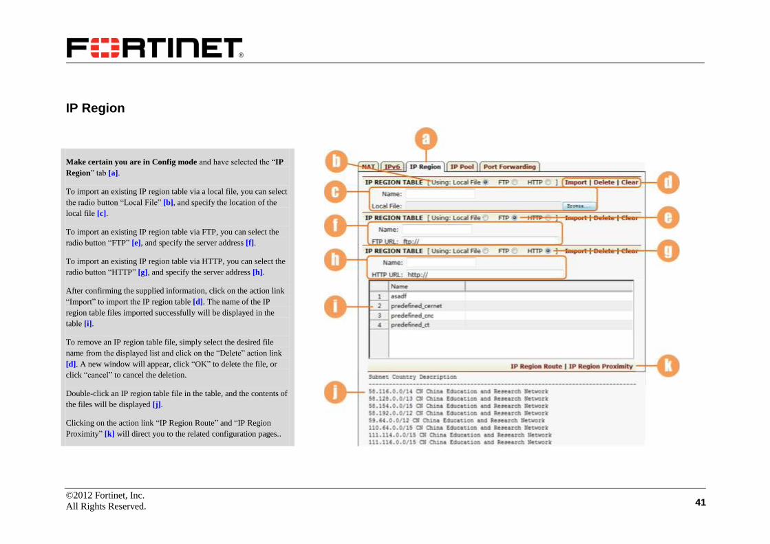
IP Region
Make certain you are in Config mode and have selected the “IP
Region” tab [a].
To import an existing IP region table via a local file, you can select
the radio button “Local File” [b], and specify the location of the
local file [c].
To import an existing IP region table via FTP, you can select the
radio button “FTP” [e], and specify the server address [f].
To import an existing IP region table via HTTP, you can select the
radio button “HTTP” [g], and specify the server address [h].
After confirming the supplied information, click on the action link
“Import” to import the IP region table [d]. The name of the IP
region table files imported successfully will be displayed in the
table [i].
To remove an IP region table file, simply select the desired file
name from the displayed list and click on the “Delete” action link
[d]. A new window will appear, click “OK” to delete the file, or
click “cancel” to cancel the deletion.
Double-click an IP region table file in the table, and the contents of
the files will be displayed [j].
Clicking on the action link “IP Region Route” and “IP Region
Proximity” [k] will direct you to the related configuration pages..
©2012 Fortinet, Inc.
All Rights Reserved. 42
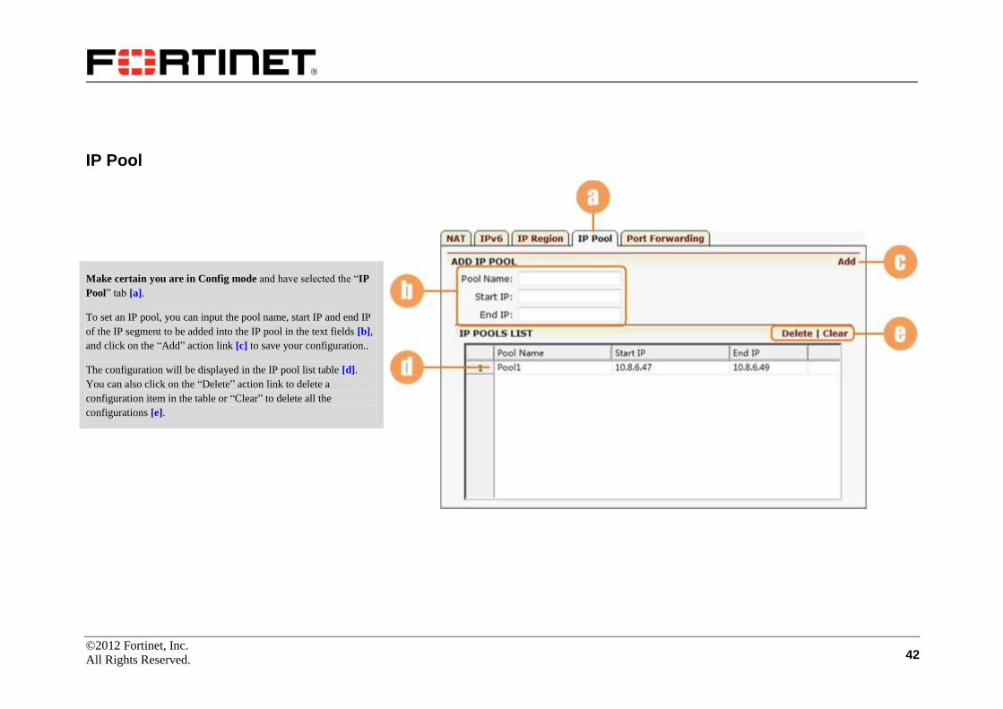
IP Pool
Make certain you are in Config mode and have selected the “IP
Pool” tab [a].
To set an IP pool, you can input the pool name, start IP and end IP
of the IP segment to be added into the IP pool in the text fields [b],
and click on the “Add” action link [c] to save your configuration..
The configuration will be displayed in the IP pool list table [d].
You can also click on the “Delete” action link to delete a
configuration item in the table or “Clear” to delete all the
configurations [e].
©2012 Fortinet, Inc.
All Rights Reserved. 43
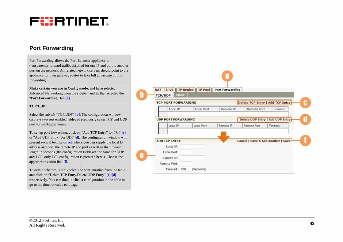
Port Forwarding
Port Forwarding allows the FortiBalancer appliance to
transparently forward traffic destined for one IP and port to another
port on the network. All related network servers should point to the
appliance for their gateway routes to take full advantage of port
forwarding.
Make certain you are in Config mode, and have selected
Advanced Networking from the sidebar, and further selected the
“Port Forwarding” tab [a].
TCP/UDP
Select the sub tab “TCP/UDP” [b]. The configuration window
displays two sort enabled tables of previously setup TCP and UDP
port forwarding schemes.
To set up port forwarding, click on “Add TCP Entry” for TCP [c]
or “Add UDP Entry” for UDP [d]. The configuration window will
present several text fields [e], where you can supply the local IP
address and port, the remote IP and port as well as the timeout
length in seconds (the configuration fields are the same for UDP
and TCP; only TCP configuration is pictured here.). Choose the
appropriate action link [f].
To delete schemes, simply select the configuration from the table
and click on “Delete TCP Entry/Delete UDP Entry” [c]/[d]
respectively. You can double-click a configuration in the table to
go to the timeout value edit page.

©2012 Fortinet, Inc.
All Rights Reserved. 44
Port Forwarding (Continue)
Mode
You may set the FortiBalancer appliance for transparent (default)
or You may set the FortiBalancer appliance for transparent
(default) or non-transparent port forwarding.
Select the sub tab “Mode” [a]. The configuration window displays
two radio buttons to set the transparent mode or non- transparent
mode [b] for port forwarding. This will affect TCP/UDP Port
Forwarding.
Select the desired mode and click the “SAVE CHANGES” button
[c] to save the settings.
©2012 Fortinet, Inc.
All Rights Reserved. 45
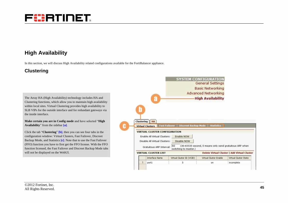
High Availability
In this section, we will discuss High Availability related configurations available for the FortiBalancer appliance.
Clustering
The Array HA (High Availability) technology includes HA and
Clustering functions, which allow you to maintain high availability
within local sites. Virtual Clustering provides high availability to
SLB VIPs for the outside interface and for redundant gateways via
the inside interface.
Make certain you are in Config mode and have selected “High
Availability” from the sidebar [a].
Click the tab “Clustering” [b], then you can see four tabs in the
configuration window: Virtual Clusters, Fast Failover, Discreet
Backup Mode, and Statistics [c]. Note that to use the Fast Failover
(FFO) function you have to first get the FFO license. With the FFO
function licensed, the Fast Failover and Discreet Backup Mode tabs
will not be displayed on the WebUI.

©2012 Fortinet, Inc.
All Rights Reserved. 46
Clustering (continue)
Virtual Clusters
Click on the buttons [a] to enable or disable virtual clusters. Set
the interval of sending gratuitous ARP packets in the text box
[b].
Select “Add Virtual Cluster” [c] and a new page will appear.
Give the virtual cluster an ID (1-255), and assign the cluster to
an interface via the selector [d]. Then, select “Save” [e]. The
information will be displayed in the table [f]. Double-click an
entry in the table, the clustering configuration window for the
entry will appear. You may also select from the created virtual
clusters via the selector [g].
General Settings
Select “General Settings” sub tab [h]. Enable the individual
cluster and/or preemption via the check boxes [i]. Set
advertisement interval in the text field [j]. Use the radio buttons
[k] to configure whether to use an authentication code or not. If
“Yes” is selected, you need to further input the password [l].
Click on the button [m] to save changes.

©2012 Fortinet, Inc.
All Rights Reserved. 47
Clustering (continue)
Virtual IP (VIP)
Make certain you select the “Virtual IP (VIP)” tab [a]. Select
the action link “Add VIP Entry” [b]. The configuration window
will present a new screen.
Supply the VIP in dotted format in the text field [c]. Next, click
on the desired action link [d]. The configured VIP will be
displayed in the table [e].
Priority
Select the “Priority” sub tab [f]. To set priority, firstly you
should add a node from “Config Management” (Please refer to
the “Config Management” chapter for further information).
Then, navigate back to the “Priority” sub tab and directly
double-click the Priority column [g] to modify the value.
Once you’ve added a virtual cluster, it will be displayed in the
table [h] under the “Virtual Clusters” tab [i]. You can use either
of the two buttons [j] to universally enable or disable the
clusters.

©2012 Fortinet, Inc.
All Rights Reserved. 48
Clustering (continue)
Fast Failover
Select the “Fast Failover” tab [a].
You can enable fast failover by checking the box [b], and set FFO
interface carrier loss timeout in the text field [c]. Then, click on the
“SAVE CHANGES” button [d] to save the settings you made.
Discreet Backup Mode
Select the “Discreet Backup Mode” tab [e].
You can enable the cluster discreet backup mode by checking the
box [f]. Note that to have the discreet backup mode work, you have
to first enable FFO. You can do this by selecting the check box [b]
under the “Fast Failover” tab.
At last, remember to click on the “SAVE CHANGES” button [g] to
save the changes.

©2012 Fortinet, Inc.
All Rights Reserved. 49
Clustering (continue)
Statistics
Select the “Statistics” tab [a]. The statistics information about all
configured clusters [b] and transition logs of virtual clusters [c] are
displayed here.
To clear cluster statistics or transition logs, users can select a
desired cluster or all clusters (all) from the selector [d] and click on
the “Clear” action link [e].

©2012 Fortinet, Inc.
All Rights Reserved. 50
HA
Array HA function is designed to provide more comprehensive and
reliable support for high availability and just two appliances are
required to deploy HA based on the major features such as floating
IP group, failover decision rule, configuration synchronization and
SSF (Session Stateful Failover).
Make certain you are in Config mode, and have selected the tab
“HA” [a], then you can see the following eight sub tabs in the
configuration window: General Information, General Config,
Groups, Condition, Decision, Synchronization, SSF and Statistics.
General Information
Click the sub tab “General Information” [b]. You will see the
status of the local unit and the peer unit in an HA domain [c], login
and synchronization status [d], and the status of link [e], which are
labeled with different marks as follows:
Active
Standby
!
Init

©2012 Fortinet, Inc.
All Rights Reserved. 51
HA (continue)
General Config
This page allows the users to perform the general HA
configurations on the FortiBalancer appliance.
Select the sub tab “General Config” [a]. The HA feature can be
enabled or disabled by the check box [b]. Set ARP interval in the
text field [c], which by default is 30, in seconds. The HA logging
function can be enabled or disabled by the check box [d]. To turn
on or off the HA FFO link, the user can use the radio buttons [e].
The HA network link can be turned on or off via the radio buttons
[f] and the primary peer IP and primary local IP can be supplied in
the text fields [g]. In addition, heart beat interval and health down
check times can be supplied in the text fields [h]. By default, heart
beat interval is 1000, in milliseconds and the number of health
down check times is 3.
To add the network secondary link, the user can click the action
link “Add” [i] to open a new configuration window. In the new
window, specify the peer IP and the local IP [j] and then click the
action link “Save” [k] to save the settings in the sorted table [l].
Click the “SAVE CHANGES” button [m] to save all the settings.

©2012 Fortinet, Inc.
All Rights Reserved. 52
HA (continue)
Groups
This function allows the users to add HA groups and further add floating
IP/IP range to the groups.
Select the sub tab “Groups” [a].
To add an HA group, supply the group ID in the field [b] and click the
action link “Add” [c]. The newly added group will be displayed in the
sorted table [d]. You can click on the action link “Delete/Clear” [e] to
delete one or clear all the groups.
Double-click an entry in the group list, and a new window will be
presented to perform more configurations for HA groups. First, select a
group from the selector [f], and then make the following configurations
about the group: specify the priority of the local group and the peer group
(which cannot be the same) and enable/disable the preempt mode [g],
enable or disable the group via the radio buttons [h], then click the action
link “Save” [i] to save the configurations.
Next, you can click the action link “Add” [j] and a new window will be
opened, where you can supply an IP address and a port [k] to add a
floating IP address into the group after saving the configuration by the
action link “Save” [l], the newly added floating IP will be displayed in the
table [m]. Similarly, an IP range can be added into a group. You click the
action link “Add” [n] and supply the start and end IP and port [o] in the
new window, then click the action link “Save” [p], the newly added IP
range will present in the table [q].

©2012 Fortinet, Inc.
All Rights Reserved. 53
HA (continue)
Condition
This function allows the users to manage the failover conditions on
the local unit or on the peer unit.
Select the sub tab “Condition” [a]. The configuration window
displays a sort enabled table for defined failover conditions.
To add a failover condition for the local unit, click the action link
“Add” [b] and a new configuration window will present several
selectors and text fields [c], where you can select the condition type
and name, specify gateway IP address, interval time and check
times, and then click the action link “Save” [d]. The configuration
will be displayed in the local condition table [e].
To add a failover condition for the peer unit, click the action link
“Add” [f] and a new configuration window will present several
selectors and text fields [g], where you can select the condition
type and name, specify gateway IP address, interval time and check
times, and then click the action link “Save” [h]. The configuration
will be displayed in the peer condition table [i].
©2012 Fortinet, Inc.
All Rights Reserved. 54
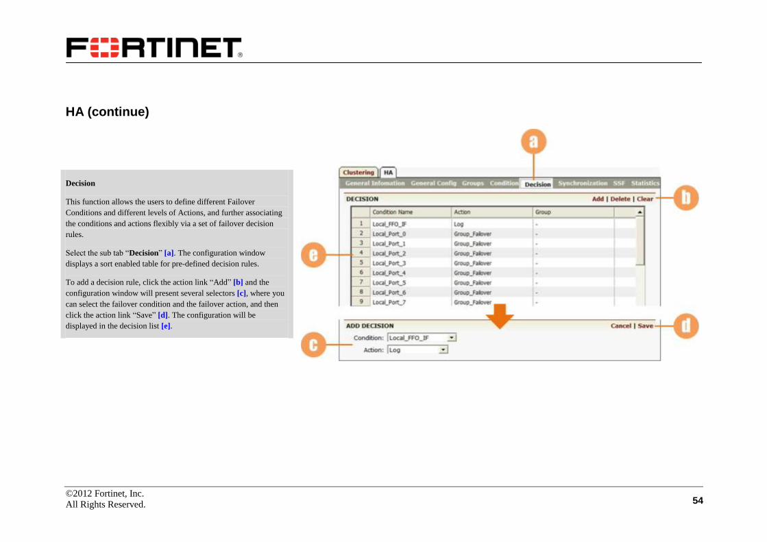
HA (continue)
Decision
This function allows the users to define different Failover
Conditions and different levels of Actions, and further associating
the conditions and actions flexibly via a set of failover decision
rules.
Select the sub tab “Decision” [a]. The configuration window
displays a sort enabled table for pre-defined decision rules.
To add a decision rule, click the action link “Add” [b] and the
configuration window will present several selectors [c], where you
can select the failover condition and the failover action, and then
click the action link “Save” [d]. The configuration will be
displayed in the decision list [e].

©2012 Fortinet, Inc.
All Rights Reserved. 55
HA (continue)
Synchronization
HA allows configuration synchronization between the units at
bootup time and during runtime of HA.
Select the sub tab “Synchronization” [a]. The configuration
window displays four radio buttons to respectively enable or
disable the bootup time synchronization and the runtime
synchronization [b].
For the bootup time synchronization, one unit will first
synchronize the configurations of the communication
links on the peer unit via the FFO link, and then
synchronize the configurations of the peer unit via the
primary link. In this way, the configurations on the two
units can be maintained consistent right after the HA
function is enabled. By default, the function is enabled.
For the runtime synchronization, one unit can
automatically synchronize its local configurations to the
peer unit after deploying related CLI commands. As a
result, the two units both have the same configurations
with each other during HA running. By default, the
function is disabled.
Click the “SAVE CHANGES” button [c] to save the settings.

©2012 Fortinet, Inc.
All Rights Reserved. 56
HA (continue)
SSF
You can disable or enable the HA SSF (Session Stateful Failover)
function globally or on a specific virtual service.
Select the “SSF” tab [a]. Enable or disable the SSF function
globally via the radio buttons [b], and specify the peer IP address in
the text field [c]. SSF can also be enabled or disabled per virtual
service via the check box [d].
Click the “SAVE CHANGES” button [e] to save the settings.
©2012 Fortinet, Inc.
All Rights Reserved. 57
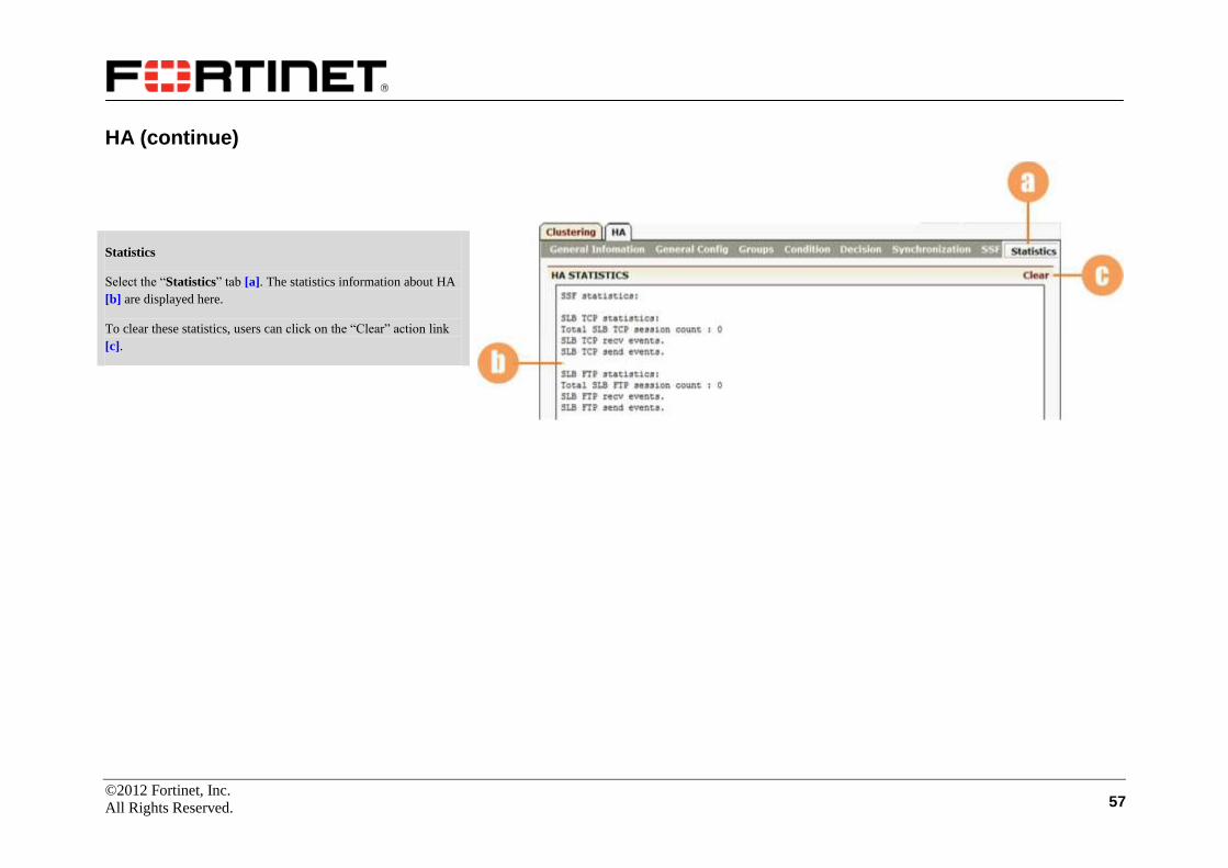
HA (continue)
Statistics
Select the “Statistics” tab [a]. The statistics information about HA
[b] are displayed here.
To clear these statistics, users can click on the “Clear” action link
[c].

©2012 Fortinet, Inc.
All Rights Reserved. 58
WebWall
The Webwall function of the FortiBalancer appliance allows you to
filter TCP, UDP and ICMP packets from the network by creating
permit/deny rules. You can enable the Webwall function on desired
interfaces, define various permit/deny access control rules and
further bind these rules to desired interfaces within the network.
Make certain you are in Config mode and have selected the
feature link “Webwall” from the sidebar [a].
Access Control
Select the “Access Control” tab [b]. You can enable the Webwall
function on desired interfaces via the check boxes [c]. There are
two modes: 0 and 1. Refer to section [d] for descriptions of the two
modes. Confirm the interfaces and modes to enable and click on
“SAVE CHANGES” [e] to make your settings take effect.
©2012 Fortinet, Inc.
All Rights Reserved. 59
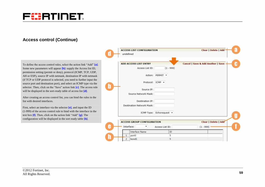
Access control (Continue)
To define the access control rules, select the action link “Add” [a].
Some new parameters will appear [b]: supply the Access list ID,
permission setting (permit or deny), protocol (ICMP, TCP, UDP,
AH or ESP), source IP with netmask, destination IP with netmask
(if TCP or UDP protocol is selected, you need to further input the
source port and destination port), and select an ICMP type via the
selector. Then, click on the “Save” action link [c]. The access rule
will be displayed in the sort-ready table of access list [d].
After creating an access control list, you can bind the rules in the
list with desired interfaces.
First, select an interface via the selector [e], and input the ID
(1-999) of the access control rule to bind with the interface in the
text box [f]. Then, click on the action link “Add” [g]. The
configuration will be displayed in the sort ready table [h].

©2012 Fortinet, Inc.
All Rights Reserved. 60
Attacking Packet Filter
Select the “Attacking Packet Filter” tab [a].
You can set the level to filter invalid packages via the radio buttons
[b]. Three levels (0, 1 and 2) are available. Refer to section [c] for
descriptions of the three levels. After setting the level properly,
click on the “SAVE CHANGES” button [d] when it appears to
save your configuration.
You can also view the filtering statistics of attacking packets in
details in the table [e].
©2012 Fortinet, Inc.
All Rights Reserved. 61
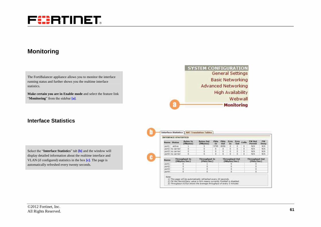
Monitoring
The FortiBalancer appliance allows you to monitor the interface
running status and further shows you the realtime interface
statistics.
Make certain you are in Enable mode and select the feature link
“Monitoring” from the sidebar [a].
Interface Statistics
Select the “Interface Statistics” tab [b] and the window will
display detailed information about the realtime interface and
VLAN (if configured) statistics in the box [c]. The page is
automatically refreshed every twenty seconds.
©2012 Fortinet, Inc.
All Rights Reserved. 62
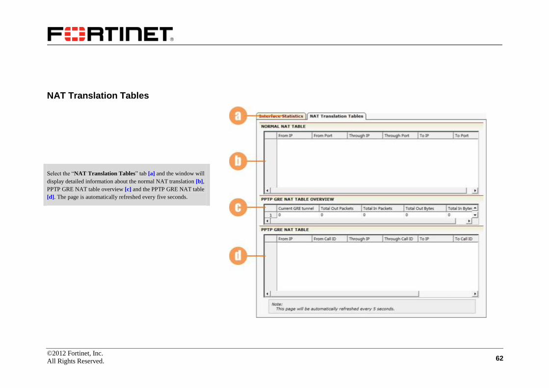
NAT Translation Tables
Select the “NAT Translation Tables” tab [a] and the window will
display detailed information about the normal NAT translation [b],
PPTP GRE NAT table overview [c] and the PPTP GRE NAT table
[d]. The page is automatically refreshed every five seconds.

©2012 Fortinet, Inc.
All Rights Reserved. 63
Server Load Balance
Server Load Balancing (SLB) allows you to distribute load and
traffic to specific groups of servers or to a specific server. The
FortiBalancer appliance supports server load balancing through
Layer 2 to 7 of the OSI network model. The Layer 4 SLB is mostly
concerned with port based load balancing, and the Layer 7 SLB is
used when you want to perform load balancing based on URLs,
HTTP headers or cookies.
Real Services
The first step in setting up your network architecture with the
FortiBalancer appliance to perform SLB tasks is to create and
configure your real services.
Make certain you are in Config mode and have selected the
feature link “Real Services” from the sidebar [a]. The
configuration window will display two tabs [b]. The default page is
“Real Services”.

©2012 Fortinet, Inc.
All Rights Reserved. 64
Real Services
Select the action link “Add Real Service Entry” [a]. The
configuration window will present a new screen.
The new screen is for you to configure real servers. Depending on
which type of real service is specified, certain parameter fields will
appear, change or disappear [b]. For TCP/TCPS, FTP,
HTTP/HTTPS or RDP real services, the max connections per
second (CPS limit) can be configured.
Then set the health check type for the real service via the selector
[c], and configure the related parameters of health check [d]. The
parameter fields may vary with different health check types. Note:
For the TCP real services, LDAP health check can be set up. For
the UDP and SIP-UDP real services, the Radius health check can
be configured.
Finish the configuration of the real service and its health check by
clicking on the desired action link [e].
WebUI supports login to a real server via Web-based SSH
connection. Click on the Web link on the real service name [f] and
a login page will appear. Supply the correct authentication
information as prompted and then you can connect to the real
server via the browser.
©2012 Fortinet, Inc.
All Rights Reserved. 65
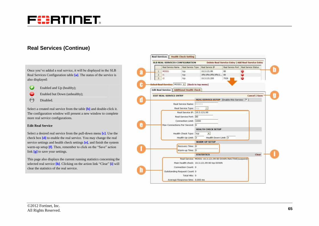
Real Services (Continue)
Once you’ve added a real service, it will be displayed in the SLB
Real Services Configuration table [a]. The status of the service is
also displayed:
Enabled and Up (healthy);
Enabled but Down (unhealthy);
Disabled.
Select a created real service from the table [b] and double-click it.
The configuration window will present a new window to complete
more real service configurations.
Edit Real Service
Select a desired real service from the pull-down menu [c]. Use the
check box [d] to enable the real service. You may change the real
service settings and health check settings [e], and finish the system
warm-up setup [f]. Then, remember to click on the “Save” action
link [g] to save your settings.
This page also displays the current running statistics concerning the
selected real service [h]. Clicking on the action link “Clear” [i] will
clear the statistics of the real service.
©2012 Fortinet, Inc.
All Rights Reserved. 66
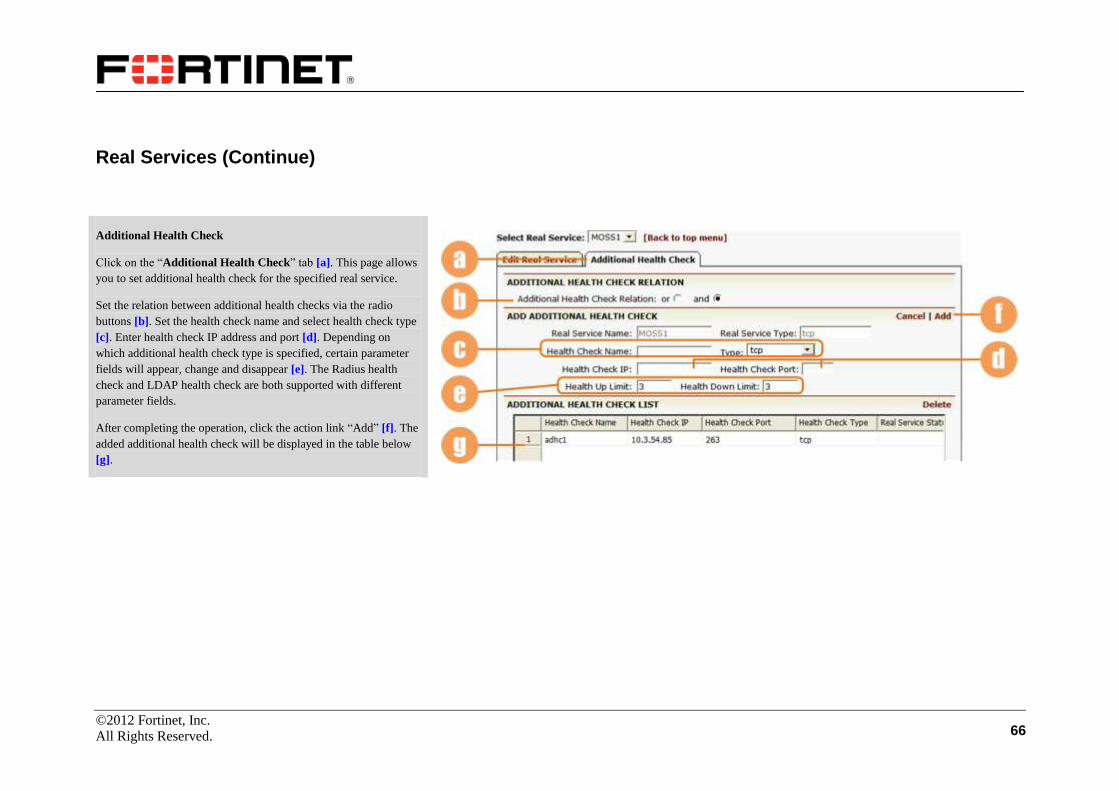
Real Services (Continue)
Additional Health Check
Click on the “Additional Health Check” tab [a]. This page allows
you to set additional health check for the specified real service.
Set the relation between additional health checks via the radio
buttons [b]. Set the health check name and select health check type
[c]. Enter health check IP address and port [d]. Depending on
which additional health check type is specified, certain parameter
fields will appear, change and disappear [e]. The Radius health
check and LDAP health check are both supported with different
parameter fields.
After completing the operation, click the action link “Add” [f]. The
added additional health check will be displayed in the table below
[g].
©2012 Fortinet, Inc.
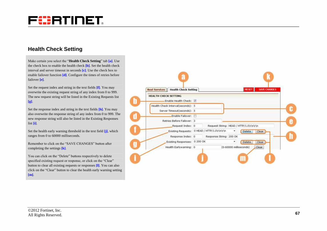
All Rights Reserved. 67
Health Check Setting
Make certain you select the “Health Check Setting” tab [a]. Use
the check box to enable the health check [b]. Set the health check
interval and server timeout in seconds [c]. Use the check box to
enable failover function [d]. Configure the times of retries before
failover [e].
Set the request index and string in the text fields [f]. You may
overwrite the existing request string of any index from 0 to 999.
The new request string will be listed in the Existing Requests list
[g].
Set the response index and string in the text fields [h]. You may
also overwrite the response string of any index from 0 to 999. The
new response string will also be listed in the Existing Responses
list [i].
Set the health early warning threshold in the text field [j], which
ranges from 0 to 60000 milliseconds.
Remember to click on the “SAVE CHANGES” button after
completing the settings [k].
You can click on the “Delete” buttons respectively to delete
specified existing request or response, or click on the “Clear”
button to clear all existing requests or responses [l]. You can also
click on the “Clear” button to clear the health early warning setting
[m].
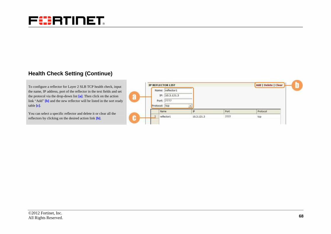
©2012 Fortinet, Inc.
All Rights Reserved. 68
Health Check Setting (Continue)
To configure a reflector for Layer 2 SLB TCP health check, input
the name, IP address, port of the reflector in the text fields and set
the protocol via the drop-down list [a]. Then click on the action
link “Add” [b] and the new reflector will be listed in the sort ready
table [c].
You can select a specific reflector and delete it or clear all the
reflectors by clicking on the desired action link [b].
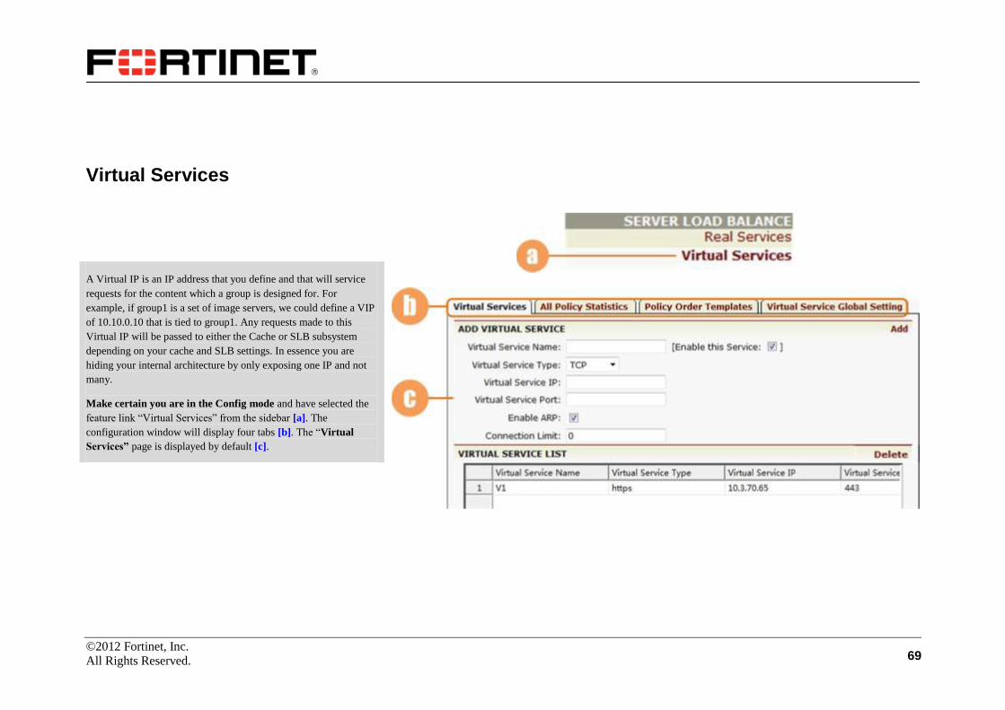
©2012 Fortinet, Inc.
All Rights Reserved. 69
Virtual Services
A Virtual IP is an IP address that you define and that will service
requests for the content which a group is designed for. For
example, if group1 is a set of image servers, we could define a VIP
of 10.10.0.10 that is tied to group1. Any requests made to this
Virtual IP will be passed to either the Cache or SLB subsystem
depending on your cache and SLB settings. In essence you are
hiding your internal architecture by only exposing one IP and not
many.
Make certain you are in the Config mode and have selected the
feature link “Virtual Services” from the sidebar [a]. The
configuration window will display four tabs [b]. The “Virtual
Services” page is displayed by default [c].

©2012 Fortinet, Inc.
All Rights Reserved. 70
Virtual Services
Set the virtual service’s name [a]. Use the check box to enable the
virtual service [b]. Select the virtual service type from the selector
[c]. Set the virtual service IP and port [d]. Use the check box to
enable ARP [e]. Set the maximum number of open connections per
virtual service [f]. Depending on which type of virtual service is
specified, certain parameter fields will appear, change or disappear.
Click on the desired action link [g] to add a virtual service. Once a
virtual service is added, it will be displayed within the table [h].
Select a virtual service in the table and double-click it, a new
configuration window will present a new series of tabs for
completing virtual services configuration.
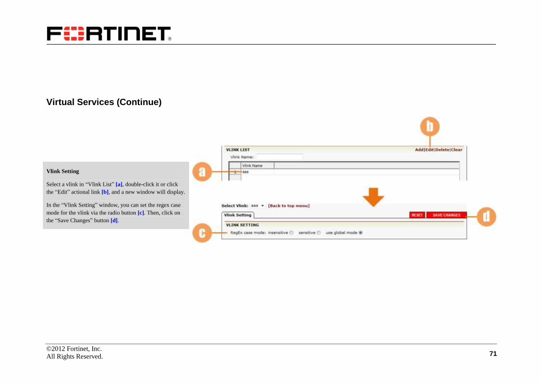
©2012 Fortinet, Inc.
All Rights Reserved. 71
Virtual Services (Continue)
Vlink Setting
Select a vlink in “Vlink List” [a], double-click it or click
the “Edit” actional link [b], and a new window will display.
In the “Vlink Setting” window, you can set the regex case
mode for the vlink via the radio button [c]. Then, click on
the “Save Changes” button [d].
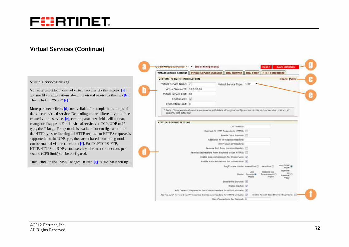
©2012 Fortinet, Inc.
All Rights Reserved. 72
Virtual Services (Continue)
Virtual Services Settings
You may select from created virtual services via the selector [a],
and modify configurations about the virtual service in the area [b].
Then, click on “Save” [c].
More parameter fields [d] are available for completing settings of
the selected virtual service. Depending on the different types of the
created virtual services [e], certain parameter fields will appear,
change or disappear. For the virtual services of TCP, UDP or IP
type, the Triangle Proxy mode is available for configuration; for
the HTTP type, redirecting all HTTP requests to HTTPS requests is
supported; for the UDP type, the packet based forwarding mode
can be enabled via the check box [f]. For TCP/TCPS, FTP,
HTTP/HTTPS or RDP virtual services, the max connections per
second (CPS limit) can be configured.
Then, click on the “Save Changes” button [g] to save your settings.

©2012 Fortinet, Inc.
All Rights Reserved. 73
Virtual Services (Continue)
Virtual Services Settings (Continue)
And also on this configuration page, if the virtual service’s port is
set to be 0, the “Port Range List” will be displayed here [a].
Administrators need to configure “Begin port” and “End port” [b]
and then click on the action link “Add” [c], and then the port range
will be added to the table [d]. For a virtual service, you can
configure three port ranges at most.
Also on this configuration page, you may assign the virtual service
to the established groups as set up earlier in the configuration
process. Use the scroll down menu to select the desired group and
the necessary policy [e]. Depending on different virtual service
types, certain parameter fields will change, appear or disappear [f].
Click on the desired action link “Add” [g]. The group and the
policy will be displayed in the sort ready table [h].
Use the scroll down menu to assign the configured real services [i]
to the virtual service. Then choose a policy order template by the
selector [j] for the virtual service.

©2012 Fortinet, Inc.
All Rights Reserved. 74
Virtual Services (Continue)
Virtual Services Statistics
Select the “Virtual Service Statistics” sub tab [a].
To view statistics of a desired virtual service, select the service
from the drop-down list [b] and the window will display related
running statistics for the virtual service, including virtual service
statistics, policy statistics, cache statistics and compression
statistics [c].
You can clear desired statistics information by clicking on the
action link “Clear” [d].

©2012 Fortinet, Inc.
All Rights Reserved. 75
Virtual Services (Continue)
URL Rewrite
Select the “URL Rewrite” sub tab [a], and a configuration screen
will appear. The contents in this configuration page are available
only if you have selected the HTTP or HTTPS type of virtual
service.
HTTP Redirect: Assign a name to the HTTP redirect policy [b].
Set the priority of the rule [c], the larger the higher. Set the HTTP
status code to send back response by selecting from the selector
[d]. Set an exact string of host header and regular expression to
match the path of the request [e]. Select a new protocol of
redirected response, either HTTP or HTTPS [f]. Then assign a new
name to the redirected response and Set a new string to replace the
part matching Path Regex [g]. Click on the desired action link
“Add” [h]. The configurations will be displayed in the table below
[i].
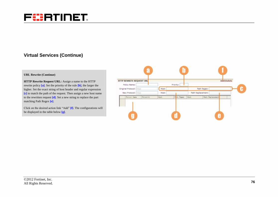
©2012 Fortinet, Inc.
All Rights Reserved. 76
Virtual Services (Continue)
URL Rewrite (Continue)
HTTP Rewrite Request URL: Assign a name to the HTTP
rewrite policy [a]. Set the priority of the rule [b], the larger the
higher. Set the exact string of host header and regular expression
[c] to match the path of the request. Then assign a new host name
to the rewritten request [d]. Set a new string to replace the part
matching Path Regex [e].
Click on the desired action link “Add” [f]. The configurations will
be displayed in the table below [g].
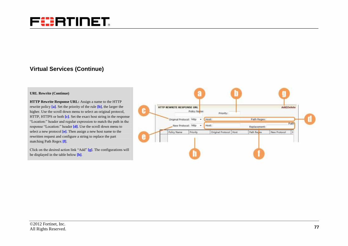
©2012 Fortinet, Inc.
All Rights Reserved. 77
Virtual Services (Continue)
URL Rewrite (Continue)
HTTP Rewrite Response URL: Assign a name to the HTTP
rewrite policy [a]. Set the priority of the rule [b], the larger the
higher. Use the scroll down menu to select an original protocol,
HTTP, HTTPS or both [c]. Set the exact host string in the response
“Location:” header and regular expression to match the path in the
response “Location:” header [d]. Use the scroll down menu to
select a new protocol [e]. Then assign a new host name to the
rewritten request and configure a string to replace the part
matching Path Regex [f].
Click on the desired action link “Add” [g]. The configurations will
be displayed in the table below [h].

©2012 Fortinet, Inc.
All Rights Reserved. 78
Virtual Services (Continue)
URL Rewrite (Continue)
HTTP Remove Request Header: Input the name of the HTTP
header to be removed from all client requests for this virtual service
in the text box [a] and click on the action link [b]. Then, the header
name will be displayed in the table [c]. To delete a header name
from the table, select it in the table and click on the action link
“Delete” [b].
HTTP Remove Response Header: Input the name of the HTTP
header to be removed from all server responses for this virtual
service in the text box [d] and click on the action link [e]. Then, the
header name will be displayed in the table [f]. To delete a header
name from the table, select it in the table and click on the action
link “Delete” [e].

©2012 Fortinet, Inc.
All Rights Reserved. 79
Virtual Services (Continue)
URL Filter
Make certain you are in Config mode and Select the “URL
Filter” sub tab [a], and a configuration screen will appear. URL
filtering includes VIP URL filtering and global URL filtering.
(Here, only VIP URL filtering configuration is described. Please
refer to the “Caching Proxy” chapter for global URL filtering
configuration.) The contents in this configuration page are
available only if you have selected the HTTP or HTTPS type of
virtual service.
URL Filtering: Enable the VIP URL filtering feature [b], and save
the change by clicking on “SAVE CHANGES” button [c]. After
saving, more configurations appear.
Alert E-mails: Set the behavior mode for filtering as active or
passive [d]. Configure the destination email address for filter
related alerts and the threshold for the number of dropped requests
before issuing the alert [e].

©2012 Fortinet, Inc.
All Rights Reserved. 80
Virtual Services (Continue)
URL Filter (Continue)
Length Based Filtering: Configure the filter length parameters for
requests coming into the network [a]. You may reset by clicking on
the action link [b].
Keyword Filtering: Assign the default filtering policy as permit or
deny [c] and supply the Match Keyword text field [b]. Then, click
the action link “Add” [e]. The restrictions will be displayed in the
sort ready table [f]. Note that if you want to change the default
global filtering policy, you must firstly delete all configured
restriction entries displayed in the table [f].
Type Filtering: Set the variable type (integer or string) [g], and
supply the variable name [h]. Click the desired action link “Add”
[i]. Then, the restrictions will be displayed in the sort ready table
[j]. To remove an existing restriction, select the desired entry in
table [j] and click on the action link “Delete” [i].
Character Based Filtering: Configure the filter character
parameters for requests coming into the network. To deny specific
requests based on URL character ranges (ASCII values); enter the
starting and ending values of the character range [k]. Click on the
action link “Add” [l].
Keyword Filtering Statistics: Display the statistics of default
policy, deny policy and permit policy of URL keyword filtering
[m].
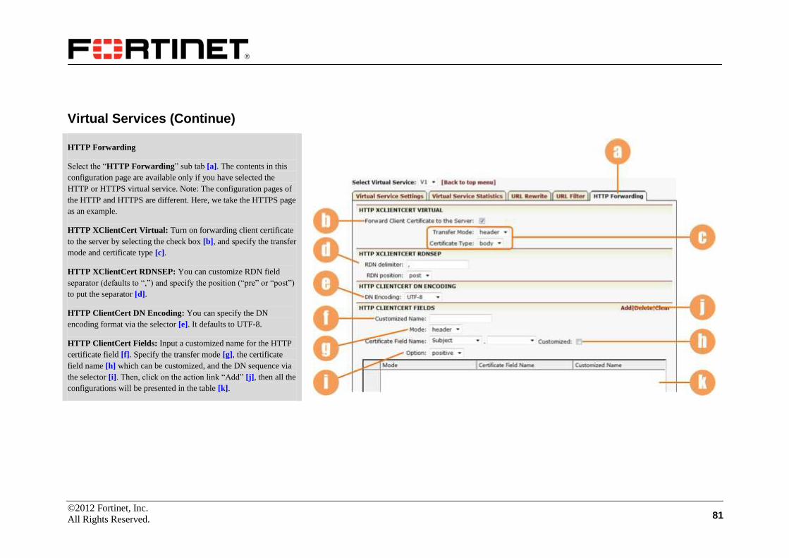
©2012 Fortinet, Inc.
All Rights Reserved. 81
Virtual Services (Continue)
HTTP Forwarding
Select the “HTTP Forwarding” sub tab [a]. The contents in this
configuration page are available only if you have selected the
HTTP or HTTPS virtual service. Note: The configuration pages of
the HTTP and HTTPS are different. Here, we take the HTTPS page
as an example.
HTTP XClientCert Virtual: Turn on forwarding client certificate
to the server by selecting the check box [b], and specify the transfer
mode and certificate type [c].
HTTP XClientCert RDNSEP: You can customize RDN field
separator (defaults to “,”) and specify the position (“pre” or “post”)
to put the separator [d].
HTTP ClientCert DN Encoding: You can specify the DN
encoding format via the selector [e]. It defaults to UTF-8.
HTTP ClientCert Fields: Input a customized name for the HTTP
certificate field [f]. Specify the transfer mode [g], the certificate
field name [h] which can be customized, and the DN sequence via
the selector [i]. Then, click on the action link “Add” [j], then all the
configurations will be presented in the table [k].
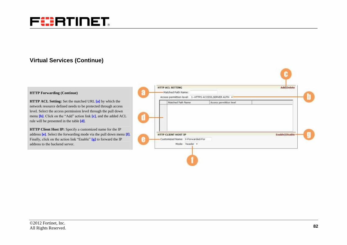
©2012 Fortinet, Inc.
All Rights Reserved. 82
Virtual Services (Continue)
HTTP Forwarding (Continue)
HTTP ACL Setting: Set the matched URL [a] by which the
network resource defined needs to be protected through access
level. Select the access permission level through the pull down
menu [b]. Click on the “Add” action link [c], and the added ACL
rule will be presented in the table [d].
HTTP Client Host IP: Specify a customized name for the IP
address [e]. Select the forwarding mode via the pull down menu [f].
Finally, click on the action link “Enable” [g] to forward the IP
address to the backend server.
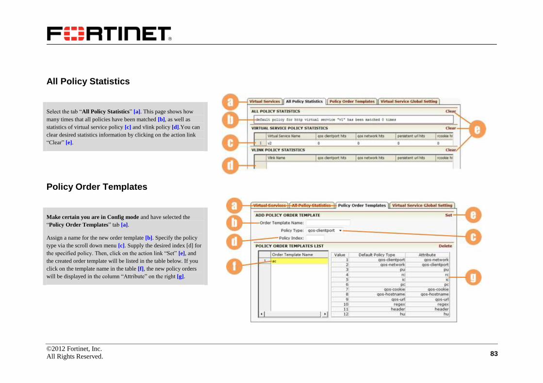
©2012 Fortinet, Inc.
All Rights Reserved. 83
All Policy Statistics
Select the tab “All Policy Statistics” [a]. This page shows how
many times that all policies have been matched [b], as well as
statistics of virtual service policy [c] and vlink policy [d].You can
clear desired statistics information by clicking on the action link
“Clear” [e].
Policy Order Templates
Make certain you are in Config mode and have selected the
“Policy Order Templates” tab [a].
Assign a name for the new order template [b]. Specify the policy
type via the scroll down menu [c]. Supply the desired index [d] for
the specified policy. Then, click on the action link “Set” [e], and
the created order template will be listed in the table below. If you
click on the template name in the table [f], the new policy orders
will be displayed in the column “Attribute” on the right [g].

©2012 Fortinet, Inc.
All Rights Reserved. 84
Virtual Service Global Setting
Click on the “Virtual Service Global Setting” tab [a]. A new
configuration window will be displayed.
Specify the proxy mode for the system via the radio buttons [b]. In
addition to the “reverse” and “transparent” modes, the system also
supports the “triangle” mode.
Enable global x-forwarded-for function by selecting the check box
[c].
Set the client certificate header name [d]. The default name is
X-Client-Cert.
Enable SLB virtual service health check via the check box [e].
Set the port range for data connection in passive FTP/FTPS in the
text fields [f]. Users can add 20 to 1000 ports to a port range. The
port range is global. It can be used for all FTP/FTPS virtual
services.
Enable or disable the global SLB regexcase mode via the radio
button [g].
Enable TCP connections soft close feature via the radio button [h].
Once any change is made, the “RESET” and “SAVE CHANGES”
buttons [i] will appear. Click on the desired button to reset or save
the change.

©2012 Fortinet, Inc.
All Rights Reserved. 85
Check Lists
A health checker is defined as one transaction of health check. It
consists of sending one message and receiving one response. A list
of health checkers can compose a health checker list, which is
identified by the health checker list name.
Note that the health checker list will work while doing health check
only when the hc_type is set as “script_tcp” or “script_udp”.
Make certain you are in Config mode and have selected “Check
Lists” from the sidebar [a]. The configuration window will display
three tabs [b]. The “Health Checker” page is displayed by default.
Health Checker
Supply a checker name [c]. Set the request index and response
index by selecting from the scroll down menu [d]. Set checker
timeout and checker flag [e]. Click on the “Save” action link [f].
The created health checker will be saved and displayed in the table
below [g].
To edit a health checker, you can select it in the table [g] and then
make desired changes. At last, remember to click on “Save” [f] to
make the changes take effect.

©2012 Fortinet, Inc.
All Rights Reserved. 86
Health List
Click on the “Health List” tab [a]. Assign a health list name [b].
Click on the action link “Add” [c]. A new health checker list is
created and will be displayed in the sort ready table below [d].
Select a desired health list and double-click it or click on the action
link “Edit” [e]. A new configuration page will be displayed.
This page is used to add members to the specified health list. Use
the scroll down menu [f] to select the created checkers. Set the
place index for the selected checker [g]. Click on the desired action
link “Add” [h]. The selected checker is added in the specified
health list, and will be displayed in the table below [i].
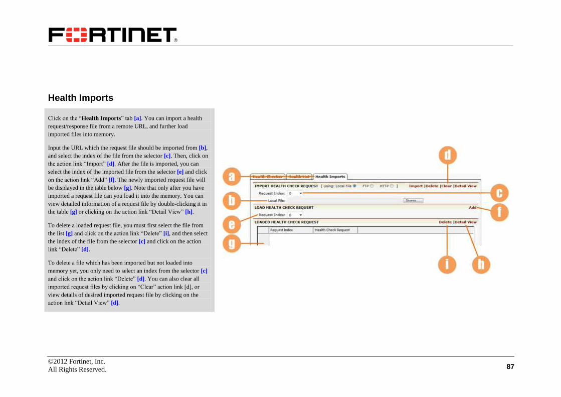
©2012 Fortinet, Inc.
All Rights Reserved. 87
Health Imports
Click on the “Health Imports” tab [a]. You can import a health
request/response file from a remote URL, and further load
imported files into memory.
Input the URL which the request file should be imported from [b],
and select the index of the file from the selector [c]. Then, click on
the action link “Import” [d]. After the file is imported, you can
select the index of the imported file from the selector [e] and click
on the action link “Add” [f]. The newly imported request file will
be displayed in the table below [g]. Note that only after you have
imported a request file can you load it into the memory. You can
view detailed information of a request file by double-clicking it in
the table [g] or clicking on the action link “Detail View” [h].
To delete a loaded request file, you must first select the file from
the list [g] and click on the action link “Delete” [i], and then select
the index of the file from the selector [c] and click on the action
link “Delete” [d].
To delete a file which has been imported but not loaded into
memory yet, you only need to select an index from the selector [c]
and click on the action link “Delete” [d]. You can also clear all
imported request files by clicking on “Clear” action link [d], or
view details of desired imported request file by clicking on the
action link “Detail View” [d].
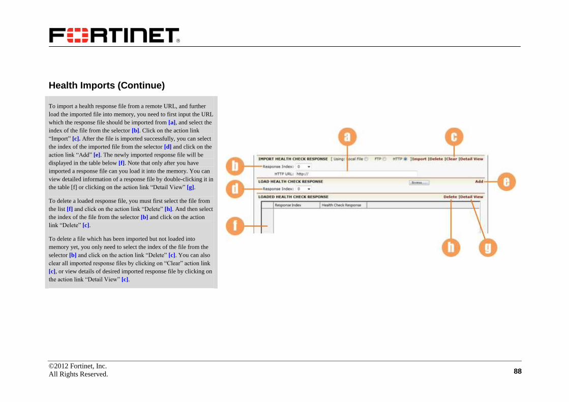
©2012 Fortinet, Inc.
All Rights Reserved. 88
Health Imports (Continue)
To import a health response file from a remote URL, and further
load the imported file into memory, you need to first input the URL
which the response file should be imported from [a], and select the
index of the file from the selector [b]. Click on the action link
“Import” [c]. After the file is imported successfully, you can select
the index of the imported file from the selector [d] and click on the
action link “Add” [e]. The newly imported response file will be
displayed in the table below [f]. Note that only after you have
imported a response file can you load it into the memory. You can
view detailed information of a response file by double-clicking it in
the table [f] or clicking on the action link “Detail View” [g].
To delete a loaded response file, you must first select the file from
the list [f] and click on the action link “Delete” [h]. And then select
the index of the file from the selector [b] and click on the action
link “Delete” [c].
To delete a file which has been imported but not loaded into
memory yet, you only need to select the index of the file from the
selector [b] and click on the action link “Delete” [c]. You can also
clear all imported response files by clicking on “Clear” action link
[c], or view details of desired imported response file by clicking on
the action link “Detail View” [c].

©2012 Fortinet, Inc.
All Rights Reserved. 89
Groups
It is time to assign the previously defined real services to groups. A
group is first defined by using the slb group command. This
command will define a group to which you may add real servers.
Make certain you are in Config mode and have selected the
feature link “Groups” from the sidebar [a]. The configuration
window will display two tabs. Click on the “Groups” tab [b].

©2012 Fortinet, Inc.
All Rights Reserved. 90
Groups
Supply the group name [a]. Select a group method from the pull
down menu [b]. Depending on the group method selected, different
parameter fields will appear for configuration [c].
After making configurations on those parameter fields, click on the
action link “Add” [d]. Then the newly created group will be
displayed in the sort ready table below [e]. The specific group can
be enabled or disabled via the check box [f]. Once any change is
made, you need to click the “Save” action link to save the
configuration.
Choose a group in the table and double-click it or click on the
action link “Edit” [g]. A new configuration page will be displayed
for more group settings.

©2012 Fortinet, Inc.
All Rights Reserved. 91
Groups (Continue)
You can modify the group method and make relevant
configurations in the area [a], and click on “Save” [b] to save your
changes. Depending on the group method selected, different
parameter fields will appear for configuration.
Input the number (1-65535) of real servers to activate in the text
field [c]; for pi group, you can also set persistence timeout for it.
Then, click on “Set” [d] to save your setting.
To assign an IP Pool to this group, you should select a pool name
via the pull down menu [e], and click on the “Add” action link [f],
the created IP pool will displayed in the following table [g].

©2012 Fortinet, Inc.
All Rights Reserved. 92
Groups (Continue)
To assign a configured real service to a newly created group, you
can select an eligible real service via the pull down menu [a],
configure required parameter [b], and set the priority of the group
member [c].
For the parameter [b], set the Weight value for the method lc, rr,
ph, pi, ic, rc, hc, hh or sslsid; set the Cookie value for pc; set the
URL value for pu; for other methods, no parameter will be required
for configuration.
Then, click on the “Add” action link [d] and the assigned real
service will appear in the table [e]. You can change the configured
parameters in the table directly, and click on “Save” [d] to save
your changes.
At this page, you can view real-time group statistics [f]. To view
the latest statistics, you can click on “Refresh” [g]. To view or clear
the latest group statistics, you can click on the action link
“Refresh” or “Clear” [g].

©2012 Fortinet, Inc.
All Rights Reserved. 93
Groups Setting
Click on the “Groups Setting” tab [a], and a new configuration
window will be displayed. Set “pi” group method timeout value for
SLB [b]. Use the pull down menu to set the SLB insert/rewrite
cookie mode [c]. Use the pull down menu to finish the insert
cookie setting [d]. Remember to click on the “SAVE CHANGES”
button to save the settings [e].
To assign an IP pool as a global IP pool, select an IP pool via the
pull down menu [f], and click on the “Add” action link [g], the
created IP pool will be displayed in the following table [h].
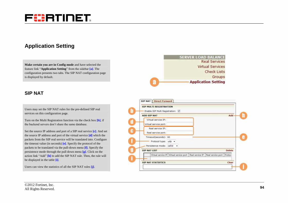
©2012 Fortinet, Inc.
All Rights Reserved. 94
Application Setting
Make certain you are in Config mode and have selected the
feature link “Application Setting” from the sidebar [a]. The
configuration presents two tabs. The SIP NAT configuration page
is displayed by default.
SIP NAT
Users may set the SIP NAT rules for the pre-defined SIP real
services on this configuration page.
Turn on the Multi Registration function via the check box [b], if
the backend servers don’t share the same database.
Set the source IP address and port of a SIP real service [c]. And set
the source IP address and port of the virtual service [d] which the
packets from the SIP real service will be translated into. Configure
the timeout value (in seconds) [e]. Specify the protocol of the
packets to be translated via the pull-down menu [f]. Specify the
persistence mode through the pull down menu [g]. Click on the
action link “Add” [h] to add the SIP NAT rule. Then, the rule will
be displayed in the table [i].
Users can view the statistics of all the SIP NAT rules [j].

©2012 Fortinet, Inc.
All Rights Reserved. 95
Direct Forward
Direct Forward is a new Layer 4 SLB module by utilizing a
multi-thread and non-lock architecture based on a multi-core
system. This new architecture has maximized the advantage of the
multi-core system. Compared with the traditional Layer 4 SLB, the
Direct Forward module provides remarkably better Layer 4 SLB
performance.
Click on the “Direct Forward” tab [a].
To enable the Direct Forward function, you can select the check
box [b].
You can also enable the Direct Forward module’s syncache
function via the check box [c]. This function can avoid synflood
attacking effectively.
Remember to click on the “SAVE CHANGES” button to save the
settings [d].

©2012 Fortinet, Inc.
All Rights Reserved. 96
Monitoring
This feature allows you to monitor the general status of the related
groups and real services of a specified virtual service, and further
view their statistic information.
Make certain you are in Enable mode and select “Monitoring”
from the sidebar [a]. The configuration presents four tabs. The
“Status page” [b] is displayed by default.
Status
Select a desired virtual service via the selector [c], and the general
status information of its related groups and real services will be
displayed in the table [d]:
: Enabled and Up (healthy);
: Enabled but Down (unhealthy);
: Disabled.
Note: The icon descriptions also apply to the “Virtual Service
Statistics” and “Real Service Statistics” pages.
You can view the statistics of a virtual service, a group or a real
service by clicking on it in the table [e].

©2012 Fortinet, Inc.
All Rights Reserved. 97
Virtual Service Statistics
Select the “Virtual Service Statistics” tab [a], and the new
configuration page will display the statistics of all virtual services
in details in the table [b]. The page is refreshed automatically every
twenty seconds.
Group Statistics
Select the “Group Statistics” tab [c], and the new page will
display the name of all groups in the table [d]. You can click on the
“View Details” link [e] of a group, and then you will be presented
with the real service details of the group on the Real Service
Statistics page. This page is refreshed automatically every twenty
seconds.
Real Service Statistics
Select the “Real Services Statistics” tab [f], and the new page will
display the statistics of all real services in details in the table [g].
The page is refreshed automatically every twenty seconds.
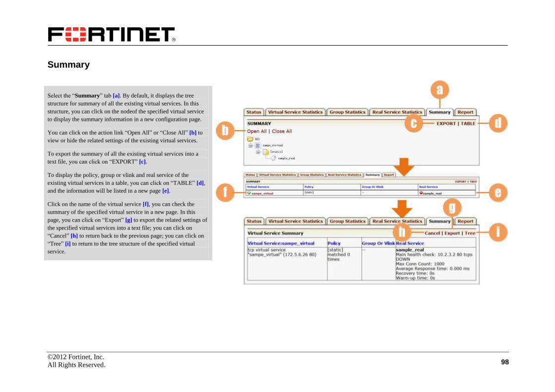
©2012 Fortinet, Inc.
All Rights Reserved. 98
Summary
Select the “Summary” tab [a]. By default, it displays the tree
structure for summary of all the existing virtual services. In this
structure, you can click on the nodeof the specified virtual service
to display the summary information in a new configuration page.
You can click on the action link “Open All” or “Close All” [b] to
view or hide the related settings of the existing virtual services.
To export the summary of all the existing virtual services into a
text file, you can click on “EXPORT” [c].
To display the policy, group or vlink and real service of the
existing virtual services in a table, you can click on “TABLE” [d],
and the information will be listed in a new page [e].
Click on the name of the virtual service [f], you can check the
summary of the specified virtual service in a new page. In this
page, you can click on “Export” [g] to export the related settings of
the specified virtual services into a text file; you can click on
“Cancel” [h] to return back to the previous page; you can click on
“Tree” [i] to return to the tree structure of the specified virtual
service.

©2012 Fortinet, Inc.
All Rights Reserved. 99
Report
Select the “Report” tab [a].
Specify the interval of the report via the drop-down list [b]. Click
the action link “Preview” [c]. Then, you will be presented with an
SLB Statistics Report file.

©2012 Fortinet, Inc.
All Rights Reserved. 100
Proxy
Compression
Setting
Make certain that you are in the Config mode and have selected
“Compression” [a]. The configuration window will present three
tabs. The “Setting” page is displayed by default [b].
Enable or disable the HTTP data compression via the check box
[c]. The selector [d] lists all configured HTTP/HTTPS virtual
services. You can choose one and click on the “Enable VS
Compression” action link [e]. The HTTP/HTTPS virtual service for
which compression feature is enabled will be displayed in the sort
ready table [f]. To disable the compression of a virtual service, you
can select the service in the table [f] and click on the “Disable VS
Compression” action link [e].
You can add a url-exclude policy for a virtual service to disable the
compression function. Input the wildcard expression [g], and select
a desired HTTP/HTTPS virtual service from the selector [h]. Click
on the action link “Add” [i], and the new configuration will be
displayed in the sort ready table below [j].

©2012 Fortinet, Inc.
All Rights Reserved. 101
Type
Click on the “Type” tab [a]. Enter a particular browser name in the
field [b]. Select one compression MIME type from the “Mime
Type” select box [c]. Click on the “Add Mime Type” action link
[d]. The added user agent and mime type will be displayed in the
table below [e].
To remove the added user agent and mime type, select a desired
entry or multi entries from the displayed list [f] and click on the
“Delete Mime Type” action link [d].
Click on “Apply Tested User Agents” [d], and the default user
agents and mime types will be displayed in the table [e].

©2012 Fortinet, Inc.
All Rights Reserved. 102
Statistics
Click on the “Statistics” tab [a].
The main window displays global compression statistics and
content statistics information [b]. Click on “Clear” action link [c],
and the statistics will default to 0.

©2012 Fortinet, Inc.
All Rights Reserved. 103
Caching Proxy
The reverse proxy cache better enhances the overall speed and
performance of your Web servers. Using the cache will improve
website performance and throughput, and will reduce server load
by moving heavily requested data closer to the end user and away
from the backend servers. You may set up limitations on queries
made to your network based on header length, request length, URL
and query length as well as ASCII character ranges and keyword
matches.
Global URL Filter
Make certain you are in Config mode and have selected the
feature link “Caching Proxy” [a]. The configuration window will
display four tabs, and the default page is “Global URL Filter” [b].
On the Global URL Filter page, you can enable the global URL
filtering feature by selecting the “Enable” check box [c]. Save the
change by clicking on the “SAVE CHANGES” button [d]. After
saving, more configurations appear.
You can set the behavior mode for filtering as active or passive [e],
and enable or disable the control characters filtering feature of
URL filter via the check box [f]. Configure the destination email
address for filter related alerts and the threshold for the number of
dropped requests before issuing the alert [g].
Click on the “SAVE CHANGES” button to save the changes [d].

©2012 Fortinet, Inc.
All Rights Reserved. 104
Global URL Filter (Continue)
Configure length-based filtering rules for requests coming into the
network [a]. Then click on the action link “SAVE CHANGES” to
save your settings [b].
Assign the default filtering policy as permit or deny [c]. Supply the
match keyword and click on the “Test” button to check whether the
inputted keyword matches one of configured regular expressions
for URL filter rules [d]. Confirm your settings, and click the action
link “Add” [e]. The restrictions will be displayed in the table [f].
Note: If you want to change the default global filtering policy, you
must first delete all configured restriction entries displayed in the
table here.
Name the variable in the text field [g], and set the variable type
(integer or string) [h]. Click the desired action link “Add” [i]. The
new restriction will be displayed in the table [j].
Configure character-based filter rules for requests coming into the
network. To deny specific requests based on URL character ranges
(ASCII values), enter the starting [k] and ending [l] values of the
character range respectively and click on the action link “Add”
[m]. The new restriction will be displayed in the table [n].
This page also displays statistics about the filter URL keyword
default policy, deny policy and permit policy [o]. You can click on
“Clear” [p] to clear all statistics.

©2012 Fortinet, Inc.
All Rights Reserved. 105
HTTP Settings
This page allows you to set/enable various parameters for your
network caching strategy. For specific HTTP settings based on
individual virtual sites, please refer to the “Virtual Services”
section in the “Server Load Balancing” chapter.
Select the “HTTP Settings” tab [a].
HTTP Setting: You may enable the following functions [b]:
Buffer response with no HTTP message length: When
enabled, responses that don’t process an “end of response”
HTTP message length indicator within the headers will still be
buffered before returning the information to the client.
Hide “Server” HTTP header from client: Removes Server
header from the response that is forwarded to the client.
Hide “Via” HTTP header from client: Does not insert Via
header into the response that is forwarded to the client.
Add “secure” keyword to Set-Cookie headers for HTTPS
Virtuals: Inserts secure keyword into the Set-Cookie header in
the responses that are sent to HTTP clients.
Add “secure” Keyword to FortiBalancer Inserted Set-Cookie
Header for HTTPS Virtuals.
OWA support: Enables or disables the subsystem, which
inserts OWA (Outlook Web Access) specific header
FRONT-END-HTTPS: on in the requests forwarded to
backend servers.

©2012 Fortinet, Inc.
All Rights Reserved. 106
HTTP Settings (Continue)
Reuse of connection to origin server: If disabled, each
connection will be used only for a single transaction after
which the connection is terminated. If enabled, each server
connection will be used by multiple transactions.
Enable Persistent Connection to Origin Server.
Persistent connection to origin server: When connection reuse
is enabled, enabling connection persistence ensures that all
transactions from the same client connection are forwarded to
the same backend server. If connection reuse is enabled but
connection persistence is disabled, then transactions from the
same client connection may be forwarded to different backend
servers. Note that the connection persistence option is only
applicable when real server persistence methods such as hash
IP or persistent cookie are disabled.
Reset non-reusable server connections.
X-Forwarded-For header insertion: Turns on/off inserting the
X-Forwarded-For header in the request forwarded to the
backend server. The client IP address is set as the value of this
header. This header is currently inserted even if the client
request already has an X-Forwarded-For header.
HTTP Modifyheader: Enables or disables HTTP modify
header.
Confirm your settings and click on “SAVE CHANGES” [a] to
make them take effect.

©2012 Fortinet, Inc.
All Rights Reserved. 107
HTTP Settings (Continue)
HTTP OWA Virtual: Set an OWA virtual service in the text field
[a]. Click on the desired action link “Add” [b], and the OWA
virtual service name will be displayed in the table [c]. To delete an
entry, select the desired entry and click on the desired action link
“Delete” [b].
HTTP XClientCert Virtual: Set an Xclientcert virtual service in
the text filed, and select the transfer mode and certificate type via
the selectors [d]. Click on the desired link “Add” [e], and then the
Xclientcert virtual service name will be displayed in the table [f].
To delete an entry, select the desired entry and click on the desire
link “Delete” [e].
HTTP Host Permissions: Set the host name for HTTP Host
Permissions [g]. Click on the desired action link “Add” [h], and
then the host will be displayed in the sort ready table [i]. To delete
an entry, select the desired entry and click on the desire link
“Delete” [h].
HTTP Method Permissions: Use the selector [j] to set the virtual
IP. Select the desired HTTP method in the field [k] and click on the
button [l] to add it into the text field [m]. You can also select one
method in the field [m] and click on the button [n] to move the
method to the “Allowed HTTP method” list.
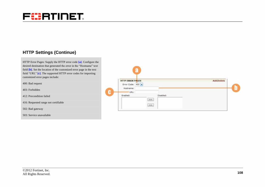
©2012 Fortinet, Inc.
All Rights Reserved. 108
HTTP Settings (Continue)
HTTP Error Pages: Supply the HTTP error code [a]. Configure the
desired destination that generated the error in the “Hostname” text
field [b]. Set the location of the customized error page in the text
field “URL” [c]. The supported HTTP error codes for importing
customized error pages include:
400: Bad request
403: Forbidden
412: Precondition failed
416: Requested range not certifiable
502: Bad gateway
503: Service unavailable
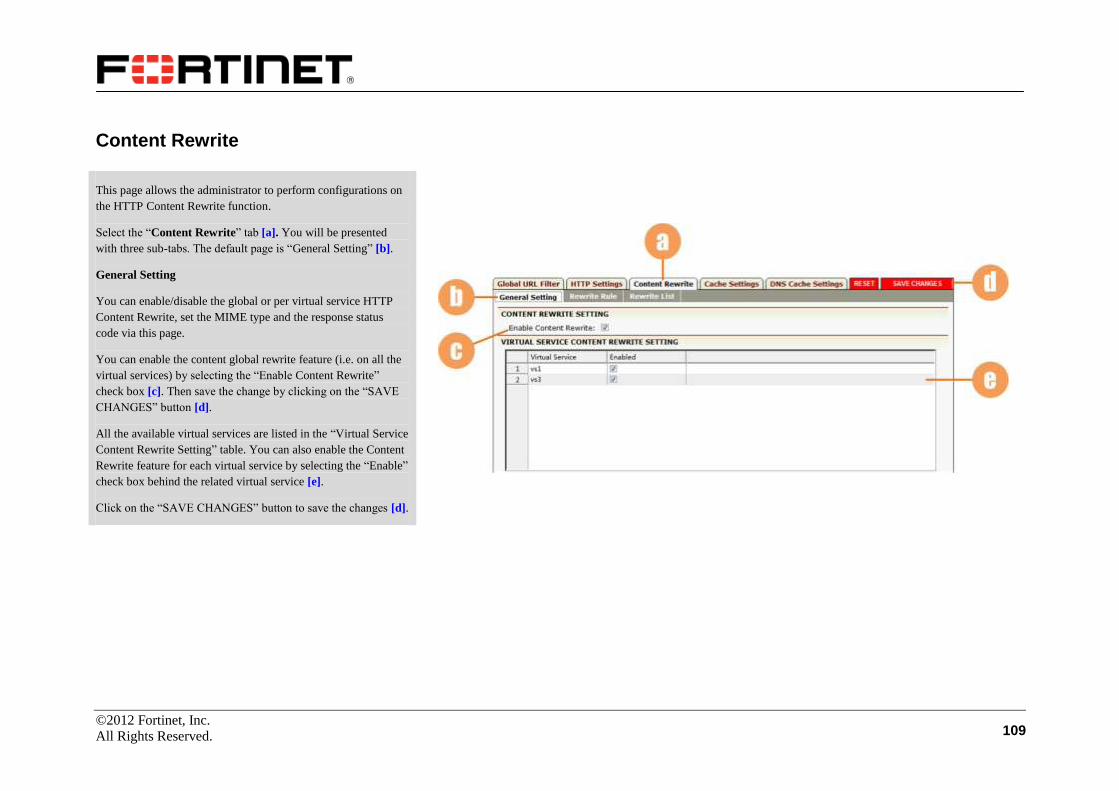
©2012 Fortinet, Inc.
All Rights Reserved. 109
Content Rewrite
This page allows the administrator to perform configurations on
the HTTP Content Rewrite function.
Select the “Content Rewrite” tab [a]. You will be presented
with three sub-tabs. The default page is “General Setting” [b].
General Setting
You can enable/disable the global or per virtual service HTTP
Content Rewrite, set the MIME type and the response status
code via this page.
You can enable the content global rewrite feature (i.e. on all the
virtual services) by selecting the “Enable Content Rewrite”
check box [c]. Then save the change by clicking on the “SAVE
CHANGES” button [d].
All the available virtual services are listed in the “Virtual Service
Content Rewrite Setting” table. You can also enable the Content
Rewrite feature for each virtual service by selecting the “Enable”
check box behind the related virtual service [e].
Click on the “SAVE CHANGES” button to save the changes [d].

©2012 Fortinet, Inc.
All Rights Reserved. 110
Content Rewrite (Continue)
You can define the MIME type to decide the types of files to
be rewritten.
To add a new MIME type, click on the action link “Add” [a],
and a new configuration window will appear.
In the new window, select a MIME type via the pull down
menu [b]. Then, click on the desired action link to save the
configurations [d]. The newly added MIME type will be
displayed in the sort ready table [c].
All the files in the selected MIME types will be rewritten, and
the other types of files will not be rewritten. By default, only
the html type of files will be rewritten.
To delete a specific MIME type, select the MIME type in the
MIME type list, and click on the “Delete” action link [e]. And
you can also click on the “Clear” action link [f] to reset the
MIME type setting to the default value “html”.
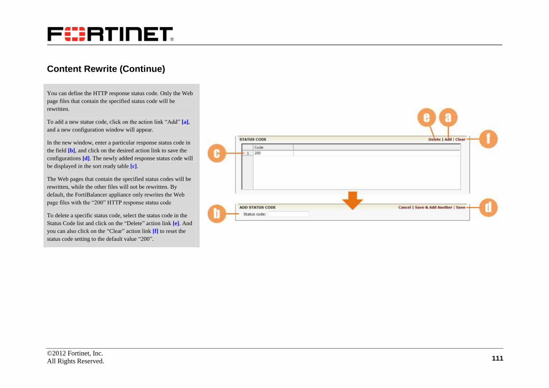
©2012 Fortinet, Inc.
All Rights Reserved. 111
Content Rewrite (Continue)
You can define the HTTP response status code. Only the Web
page files that contain the specified status code will be
rewritten.
To add a new statue code, click on the action link “Add” [a],
and a new configuration window will appear.
In the new window, enter a particular response status code in
the field [b], and click on the desired action link to save the
configurations [d]. The newly added response status code will
be displayed in the sort ready table [c].
The Web pages that contain the specified status codes will be
rewritten, while the other files will not be rewritten. By
default, the FortiBalancer appliance only rewrites the Web
page files with the “200” HTTP response status code
To delete a specific status code, select the status code in the
Status Code list and click on the “Delete” action link [e]. And
you can also click on the “Clear” action link [f] to reset the
status code setting to the default value “200”.
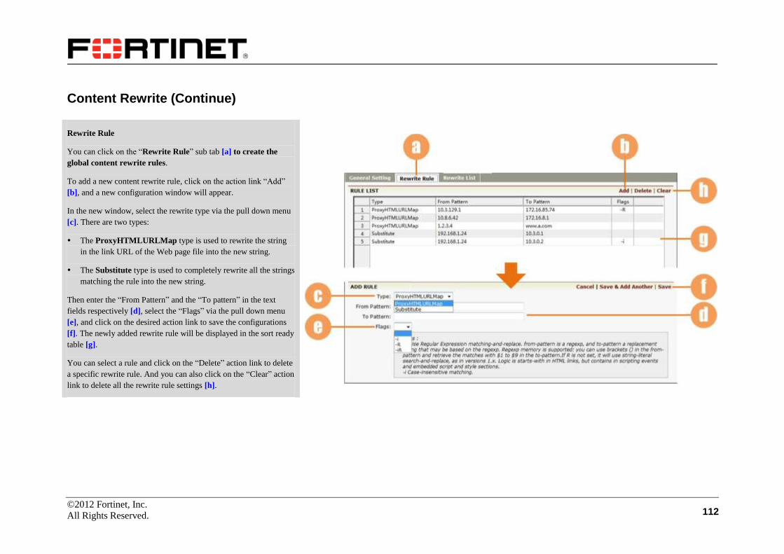
©2012 Fortinet, Inc.
All Rights Reserved. 112
Content Rewrite (Continue)
Rewrite Rule
You can click on the “Rewrite Rule” sub tab [a] to create the
global content rewrite rules.
To add a new content rewrite rule, click on the action link “Add”
[b], and a new configuration window will appear.
In the new window, select the rewrite type via the pull down menu
[c]. There are two types:
The ProxyHTMLURLMap type is used to rewrite the string
in the link URL of the Web page file into the new string.
The Substitute type is used to completely rewrite all the strings
matching the rule into the new string.
Then enter the “From Pattern” and the “To pattern” in the text
fields respectively [d], select the “Flags” via the pull down menu
[e], and click on the desired action link to save the configurations
[f]. The newly added rewrite rule will be displayed in the sort ready
table [g].
You can select a rule and click on the “Delete” action link to delete
a specific rewrite rule. And you can also click on the “Clear” action
link to delete all the rewrite rule settings [h].

©2012 Fortinet, Inc.
All Rights Reserved. 113
Content Rewrite (Continue)
Rewrite List
The administrator can define the filter regex to permit or deny
rewriting of the files that match the filter regex per virtual service.
To specify the filter regex, the administrator should first define a
URL list, and then add filter regexes into the URL list.
You can click on the “Rewrite List” sub tab [a] to create the
content rewrite URL.
To add a new rewrite URL list, click on the action link “Add” [b],
and a new configuration window will appear.
In the new window, enter the “List Name” and the “Regex” in the
text fields [c], and click on the desired action link to save the
configurations [d].
The “Regex” is used to match the string in the Web page file. Once
a URL list is associated with a virtual service, all the files that
contain the string matching the regex will be rewritten.
The newly added rewrite URL list will be displayed in the sort
ready table [e]. You can select a row and click on the “Delete”
action link to delete a specific URL list, or you can click on the
“Clear” action link to delete all URL lists [f].

©2012 Fortinet, Inc.
All Rights Reserved. 114
Content Rewrite (Continue)
The administrator can associate a URL list with a specific virtual
service to permit/deny rewriting certain kinds of Web page files on
the virtual services.
To define a permit URL list for a virtual service, click on the action
link “Add” [a], and a new configuration window will appear.
In the new window, select the virtual service and the URL list via
the pull down menus [b], and click on the desired action link to
save the configurations [c].
The newly added association will be displayed in the sort ready
table [d]. All the Web page files that contain strings matching the
regex in the URL list will be rewritten. You can select a virtual
service from the pull down menu [e] to view the associated permit
URL lists with it.
You can select a row and click on the “Delete” action link to delete
a specific association. And you can also click on the “Clear” action
link to delete all associations [f].
Note: A virtual service can be associated with only one URL list.
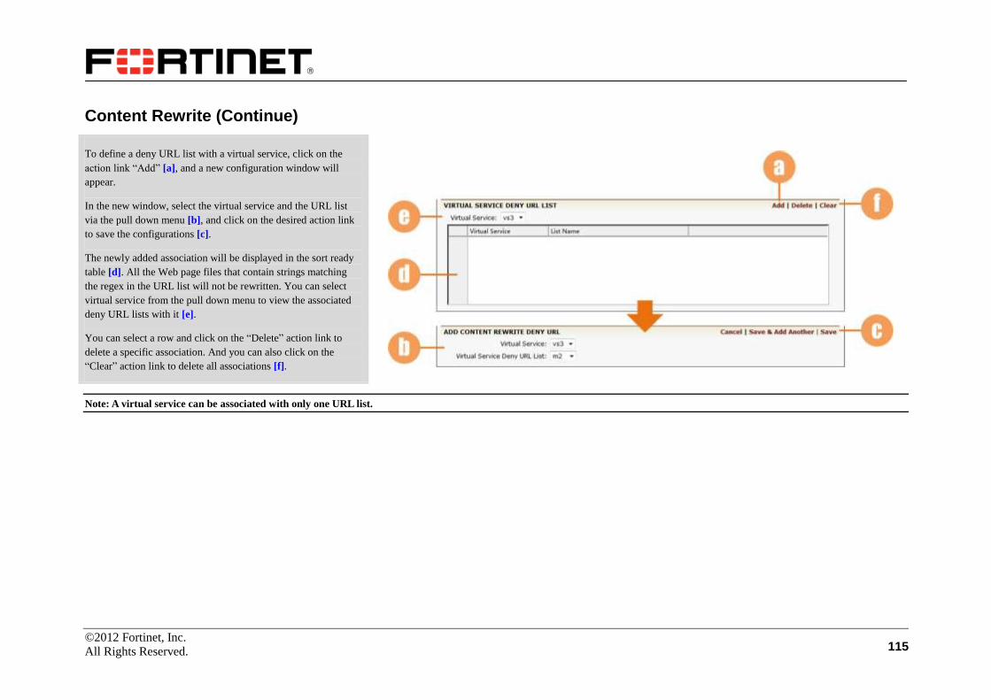
©2012 Fortinet, Inc.
All Rights Reserved. 115
Content Rewrite (Continue)
To define a deny URL list with a virtual service, click on the
action link “Add” [a], and a new configuration window will
appear.
In the new window, select the virtual service and the URL list
via the pull down menu [b], and click on the desired action link
to save the configurations [c].
The newly added association will be displayed in the sort ready
table [d]. All the Web page files that contain strings matching
the regex in the URL list will not be rewritten. You can select
virtual service from the pull down menu to view the associated
deny URL lists with it [e].
You can select a row and click on the “Delete” action link to
delete a specific association. And you can also click on the
“Clear” action link to delete all associations [f].
Note: A virtual service can be associated with only one URL list.
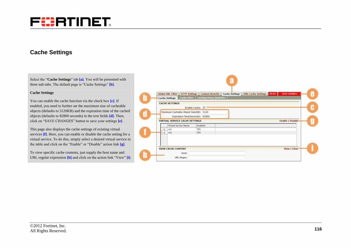
©2012 Fortinet, Inc.
All Rights Reserved. 116
Cache Settings
Select the “Cache Settings” tab [a]. You will be presented with
three sub-tabs. The default page is “Cache Settings” [b].
Cache Settings
You can enable the cache function via the check box [c]. If
enabled, you need to further set the maximum size of cacheable
objects (defaults to 5120KB) and the expiration time of the cached
objects (defaults to 82800 seconds) in the text fields [d]. Then,
click on “SAVE CHANGES” button to save your settings [e].
This page also displays the cache settings of existing virtual
services [f]. Here, you can enable or disable the cache setting for a
virtual service. To do this, simply select a desired virtual service in
the table and click on the “Enable” or “Disable” action link [g].
To view specific cache contents, just supply the host name and
URL regular expression [h] and click on the action link “View” [i].

©2012 Fortinet, Inc.
All Rights Reserved. 117
Cache Settings (Continue)
Cache Filter
Select the sub-tab “Cache Filter” [a].
You can enable the cache filter function via the check box [b].
Remember to click on the “SAVE CHANGES” button [c] to save
your change.
To add a cache filter rule, supply the host name, regular expression
and TTL in the text fields [d] and choose to enable (yes) or disable
(no) the Cache or URL query function for the host via the selectors
[e]. Then, click on the action link “Add” [f], and the rule will be
displayed in the table [g].
The “Cache Host Name” selector lists all hosts configured with
cache filter rules. You can choose one from the selector [h] to view
related cache filter statistics. To clear the statistics, simply click on
the action link “Clear” [i].

©2012 Fortinet, Inc.
All Rights Reserved. 118
Cache Settings (Continue)
Caching Proxy Statistics
Click on the “Caching Proxy Statistics” sub-tab [a].
The window displays the statistics information about reverse proxy
cache [b], including basic statistics and advanced statistics.
You can select a desired virtual service from the selector [c] to
view its cache proxy statistics.
To clear the statistics, simply click on the action link “Clear” [d].

©2012 Fortinet, Inc.
All Rights Reserved. 119
DNS Cache Settings
DNS Cache Settings
Click on the “DNS Cache Settings” tab [a]. Enable the DNS cache
via the check box [b]. Set the time to live for the cache entry in the
text field [c].
In “DNS CACHE STATIC ENTRIES”, enter the desired host
name and IP in the text fields [d] and click on the action link
“Add” [e]. Then the added host will be displayed in the table [f].
Remember to click on the “SAVE CHANGES” button [g] after
changing the DNS Cache settings. You can reset the configuration
by clicking on the “RESET” button [g].
In “DNS CACHE STATISTICS”, all DNS cache statistics
information is displayed [h].

©2012 Fortinet, Inc.
All Rights Reserved. 120
SSL
To do SSL configurations, make certain you are in Config mode
and select the “SSL” feature link [a]. The configuration window
will display five tabs: Global Settings, Global CRL, Virtual Hosts,
Real Hosts, and SSL Errors. The Global Settings tab [b] is
displayed by default.
Global Settings
On this page, you can complete the following SSL global settings:
specify whether to ignore the close_notify alert messages [c],
whether to enable sending the close_notify alert messages [d],
whether to enable the certificate verification function [e], whether
to enable the SSL renegotiation function [f], whether to enable the
CRL (Certification Revocation List) memory support function [g],
and set the session cache idle timeout (in seconds) [h].
Then, confirm your settings and click on “SAVE CHANGES” [i]
to make them take effect.
To add a global CRL, click on the action link “Add” [j], and a new
configuration window will appear.
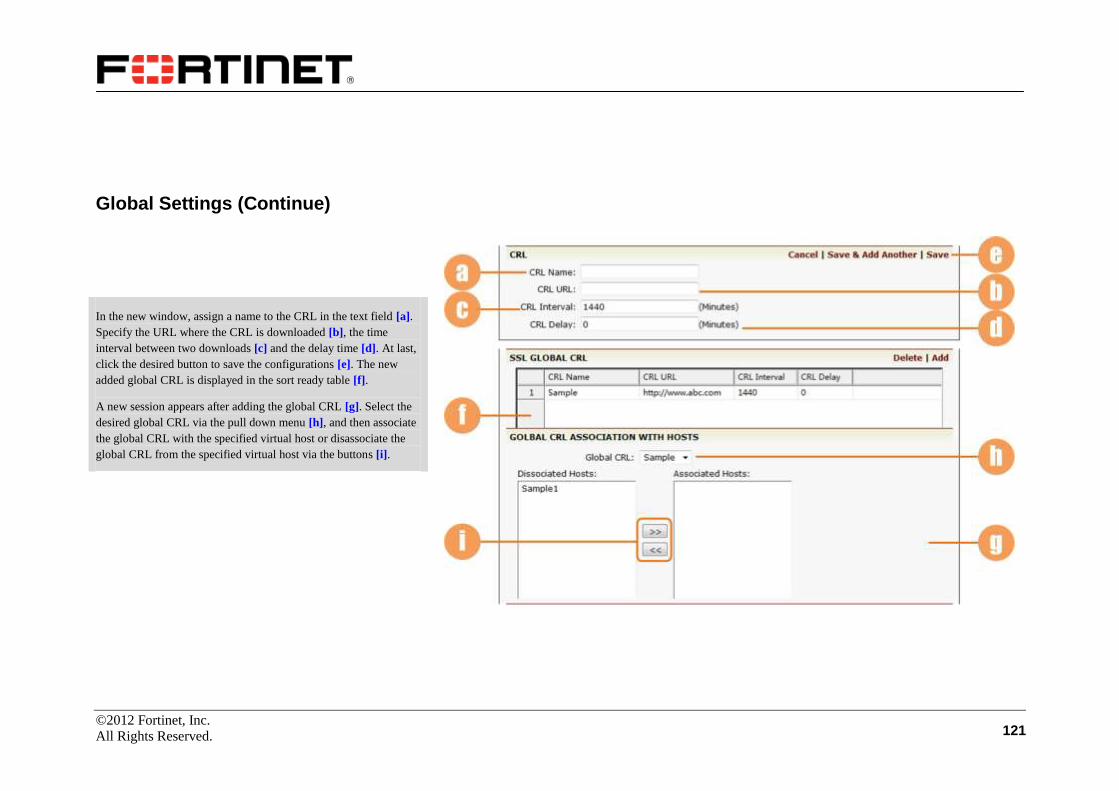
©2012 Fortinet, Inc.
All Rights Reserved. 121
Global Settings (Continue)
In the new window, assign a name to the CRL in the text field [a].
Specify the URL where the CRL is downloaded [b], the time
interval between two downloads [c] and the delay time [d]. At last,
click the desired button to save the configurations [e]. The new
added global CRL is displayed in the sort ready table [f].
A new session appears after adding the global CRL [g]. Select the
desired global CRL via the pull down menu [h], and then associate
the global CRL with the specified virtual host or disassociate the
global CRL from the specified virtual host via the buttons [i].

©2012 Fortinet, Inc.
All Rights Reserved. 122
Global Settings (Continue)
You can import a trusted CA certificate via selecting a local file,
using TFTP or manually inputting the certificate.
To import from a local file, specify the file path in the text field [a];
to import via TFTP, select the radio button “TFTP” and supply the
server address [b]; to import via manual input, select the radio
button “Manual Input” and supply the global certificate in the text
field [c]. After confirming the supplied information, click on the
action link “Import” to import the CA certificate [d].
To view the global CA certificate information, click on the “View”
action link [e]. Then a new window displays all global CA
certificates in numeric order [f]. You can view the simple or
complete mode of certificates via the radio buttons [g].
You can also delete an undesired certificate. Select the sequence
number of the certificate from the list [h] and click on the “Delete”
button [i] to start deleting.
You can further import or view CRL CA certificate by following
the steps of importing or viewing global CA certificate.

©2012 Fortinet, Inc.
All Rights Reserved. 123
Global CRL
Select the “Global CRL” tab [a] to enter the configuration
windows.
To import a CRL filter, select the specific CDP name via the pull
down menu. Specify the TFTP IP address and the remote file name
[b], and then click on the “Import” button to import the CRL filter
[c].
To delete a CRL filter, select an entry from the CRL filter table [d]
and then click on the “Delete” button to delete the CRL filter [e].
To modify the CRL study interval, select the specific CDP name
via the pull down menu [f]. Specify the study interval [g], in
minutes, and then click on the “Set” button [h]. The new study
interval will be displayed in the table [i].

©2012 Fortinet, Inc.
All Rights Reserved. 124
Virtual Hosts
Make certain that you have already created virtual hosts via the
Virtual Services configuration.
Select the “Virtual Hosts” tab [a]. A list of SSL virtual hosts will
be displayed in the sort ready table [b].
To add a virtual host, click on the action link “Add” [c], and supply
the virtual host name and select an SLB virtual service [d], and
then click on the desired action link [e]. Then, the newly added
host names will be displayed in the table [b].
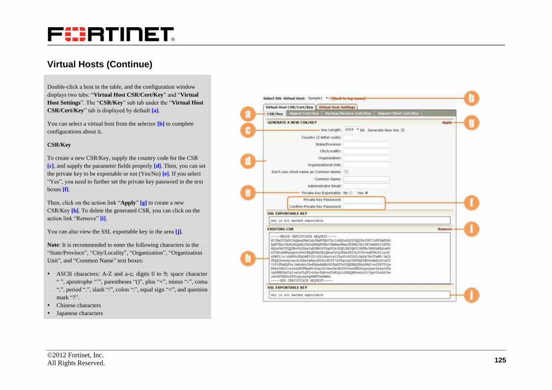
©2012 Fortinet, Inc.
All Rights Reserved. 125
Virtual Hosts (Continue)
Double-click a host in the table, and the configuration window
displays two tabs: “Virtual Host CSR/Cert/Key” and “Virtual
Host Settings”. The “CSR/Key” sub tab under the “Virtual Host
CSR/Cert/Key” tab is displayed by default [a].
You can select a virtual host from the selector [b] to complete
configurations about it.
CSR/Key
To create a new CSR/Key, supply the country code for the CSR
[c], and supply the parameter fields properly [d]. Then, you can set
the private key to be exportable or not (Yes/No) [e]. If you select
“Yes”, you need to further set the private key password in the text
boxes [f].
Then, click on the action link “Apply” [g] to create a new
CSR/Key [h]. To delete the generated CSR, you can click on the
action link “Remove” [i].
You can also view the SSL exportable key in the area [j].
Note: It is recommended to enter the following characters in the
“State/Province”, “City/Locality”, “Organization”, “Organization
Unit”, and “Common Name” text boxes:
ASCII characters: A-Z and a-z; digits 0 to 9; space character
“ ”, apostrophe “’”, parentheses “()”, plus “+”, minus “-”, coma
“,”, period “.”, slash “/”, colon “:”, equal sign “=”, and question
mark “?”.
Chinese characters
Japanese characters
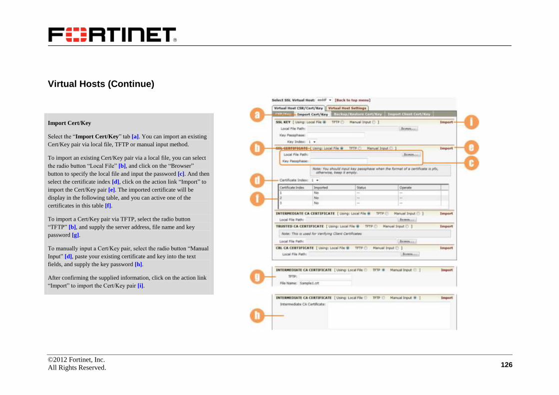
©2012 Fortinet, Inc.
All Rights Reserved. 126
Virtual Hosts (Continue)
Import Cert/Key
Select the “Import Cert/Key” tab [a]. You can import an existing
Cert/Key pair via local file, TFTP or manual input method.
To import an existing Cert/Key pair via a local file, you can select
the radio button “Local File” [b], and click on the “Browser”
button to specify the local file and input the password [c]. And then
select the certificate index [d], click on the action link “Import” to
import the Cert/Key pair [e]. The imported certificate will be
display in the following table, and you can active one of the
certificates in this table [f].
To import a Cert/Key pair via TFTP, select the radio button
“TFTP” [b], and supply the server address, file name and key
password [g].
To manually input a Cert/Key pair, select the radio button “Manual
Input” [d], paste your existing certificate and key into the text
fields, and supply the key password [h].
After confirming the supplied information, click on the action link
“Import” to import the Cert/Key pair [i].

©2012 Fortinet, Inc.
All Rights Reserved. 127
Virtual Hosts (Continue)
Import Cert/Key (Continue)
Double-click the certificate index in the index table [a], a new
window will display the detail information of the imported
certificate [b].
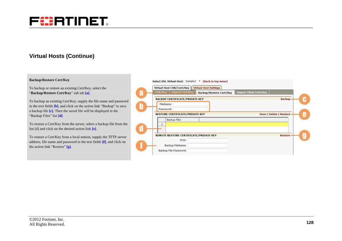
©2012 Fortinet, Inc.
All Rights Reserved. 128
Virtual Hosts (Continue)
Backup/Restore Cert/Key
To backup or restore an existing Cert/Key, select the
“Backup/Restore Cert/Key” sub tab [a].
To backup an existing Cert/Key, supply the file name and password
in the text fields [b], and click on the action link “Backup” to save
a backup file [c]. Then the saved file will be displayed in the
“Backup Files” list [d].
To restore a Cert/Key from the server, select a backup file from the
list [d] and click on the desired action link [e].
To restore a Cert/Key from a local station, supply the TFTP server
address, file name and password in the text fields [f], and click on
the action link “Restore” [g].
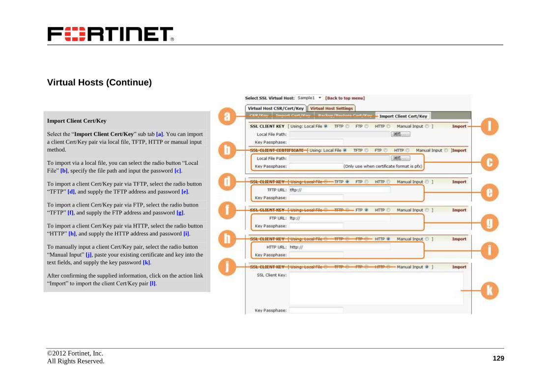
©2012 Fortinet, Inc.
All Rights Reserved. 129
Virtual Hosts (Continue)
Import Client Cert/Key
Select the “Import Client Cert/Key” sub tab [a]. You can import
a client Cert/Key pair via local file, TFTP, HTTP or manual input
method.
To import via a local file, you can select the radio button “Local
File” [b], specify the file path and input the password [c].
To import a client Cert/Key pair via TFTP, select the radio button
“TFTP” [d], and supply the TFTP address and password [e].
To import a client Cert/Key pair via FTP, select the radio button
“TFTP” [f], and supply the FTP address and password [g].
To import a client Cert/Key pair via HTTP, select the radio button
“HTTP” [h], and supply the HTTP address and password [i].
To manually input a client Cert/Key pair, select the radio button
“Manual Input” [j], paste your existing certificate and key into the
text fields, and supply the key password [k].
After confirming the supplied information, click on the action link
“Import” to import the client Cert/Key pair [l].

©2012 Fortinet, Inc.
All Rights Reserved. 130
Virtual Hosts (Continue)
Virtual Host Settings
To execute virtual host settings, make sure that you have already
generated a CSR or imported a certificate and key. Select the
“Virtual Host Settings” tab [a], and the configuration window will
display two sub tabs “Basic Settings” [b] and “Advanced
Settings” [c].
Basic Settings
On this configuration page, you can enable SSL on this virtual host
by selecting the check box “Enable SSL” [d].
You can view certificate information in the configuration window
[e]. Select the display mode via the radio buttons [f]. If you choose
the “Complete” mode, complete certificate information will be
displayed.

©2012 Fortinet, Inc.
All Rights Reserved. 131
Virtual Hosts (Continue)
Basic Settings (Continue)
On this configuration page, you can also view intermediate CA
certificate, trusted CA certificate, CRL CA certificate and client
certificate information.
Select the display mode of certificate information (simple or
complete) via the radio buttons [a].
You can click on the “Clear” action link [b] to remove the
certificate.
You can also view SSL statistics information on this page [c].
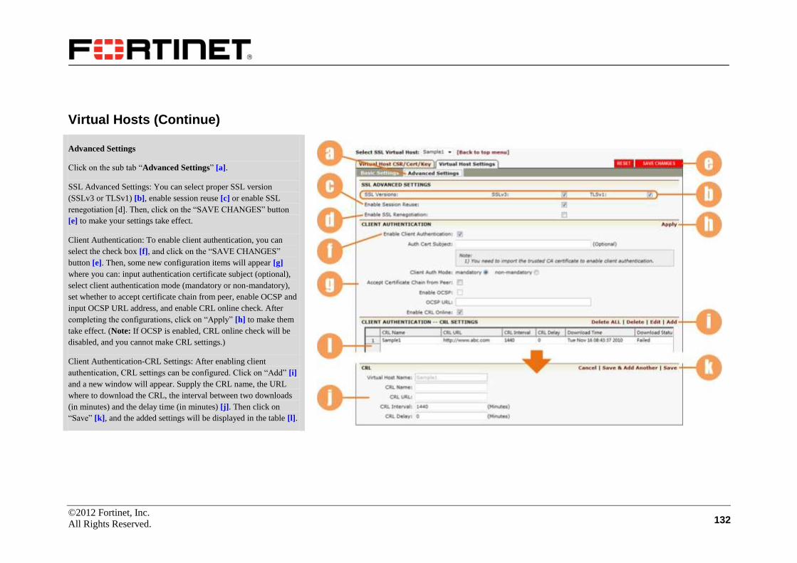
©2012 Fortinet, Inc.
All Rights Reserved. 132
Virtual Hosts (Continue)
Advanced Settings
Click on the sub tab “Advanced Settings” [a].
SSL Advanced Settings: You can select proper SSL version
(SSLv3 or TLSv1) [b], enable session reuse [c] or enable SSL
renegotiation [d]. Then, click on the “SAVE CHANGES” button
[e] to make your settings take effect.
Client Authentication: To enable client authentication, you can
select the check box [f], and click on the “SAVE CHANGES”
button [e]. Then, some new configuration items will appear [g]
where you can: input authentication certificate subject (optional),
select client authentication mode (mandatory or non-mandatory),
set whether to accept certificate chain from peer, enable OCSP and
input OCSP URL address, and enable CRL online check. After
completing the configurations, click on “Apply” [h] to make them
take effect. (Note: If OCSP is enabled, CRL online check will be
disabled, and you cannot make CRL settings.)
Client Authentication-CRL Settings: After enabling client
authentication, CRL settings can be configured. Click on “Add” [i]
and a new window will appear. Supply the CRL name, the URL
where to download the CRL, the interval between two downloads
(in minutes) and the delay time (in minutes) [j]. Then click on
“Save” [k], and the added settings will be displayed in the table [l].
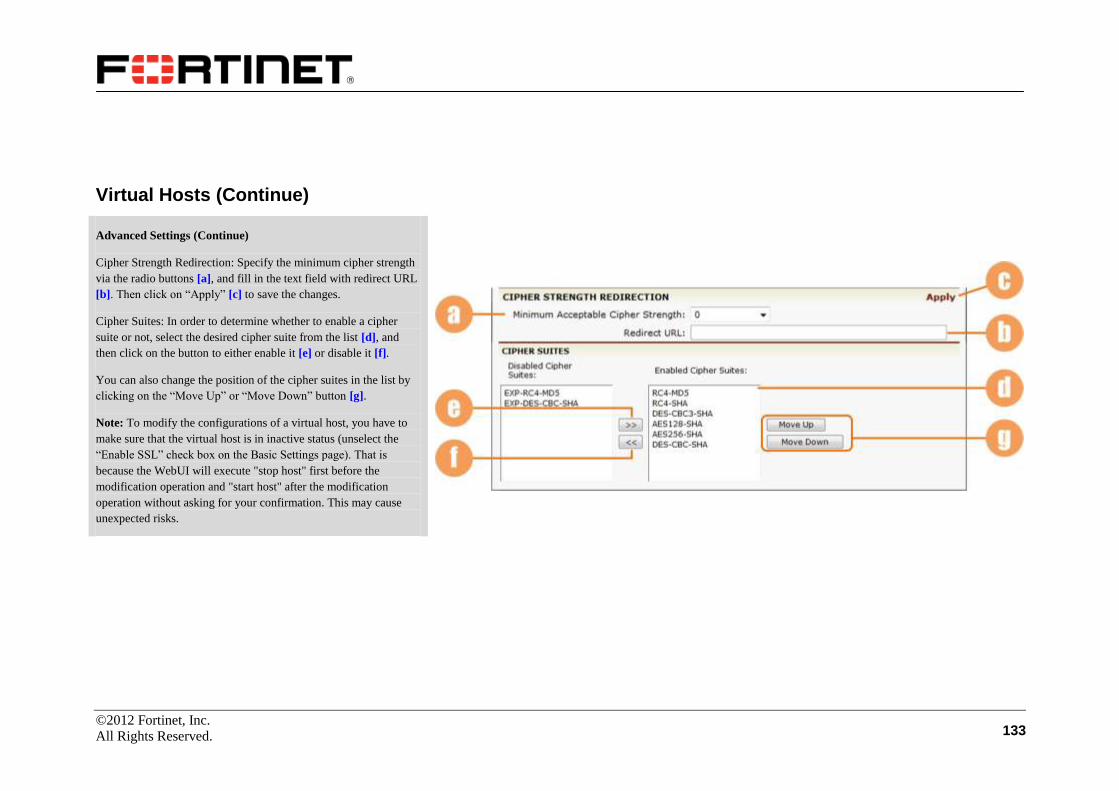
©2012 Fortinet, Inc.
All Rights Reserved. 133
Virtual Hosts (Continue)
Advanced Settings (Continue)
Cipher Strength Redirection: Specify the minimum cipher strength
via the radio buttons [a], and fill in the text field with redirect URL
[b]. Then click on “Apply” [c] to save the changes.
Cipher Suites: In order to determine whether to enable a cipher
suite or not, select the desired cipher suite from the list [d], and
then click on the button to either enable it [e] or disable it [f].
You can also change the position of the cipher suites in the list by
clicking on the “Move Up” or “Move Down” button [g].
Note: To modify the configurations of a virtual host, you have to
make sure that the virtual host is in inactive status (unselect the
“Enable SSL” check box on the Basic Settings page). That is
because the WebUI will execute "stop host" first before the
modification operation and "start host" after the modification
operation without asking for your confirmation. This may cause
unexpected risks.
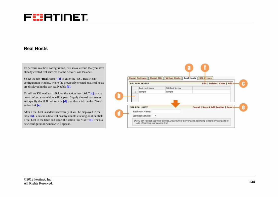
©2012 Fortinet, Inc.
All Rights Reserved. 134
Real Hosts
To perform real host configuration, first make certain that you have
already created real services via the Server Load Balance.
Select the tab “Real Hosts” [a] to enter the “SSL Real Hosts”
configuration window, where the previously created SSL real hosts
are displayed in the sort ready table [b].
To add an SSL real host, click on the action link “Add” [c], and a
new configuration widow will appear. Supply the real host name
and specify the SLB real service [d], and then click on the “Save”
action link [e].
After a real host is added successfully, it will be displayed in the
table [b]. You can edit a real host by double-clicking on it or click
a real host in the table and select the action link “Edit” [f]. Then, a
new configuration window will appear.

©2012 Fortinet, Inc.
All Rights Reserved. 135
Real Hosts (Continue)
Double-click the real host name in the list box, and the
configuration window will display two tabs “Real Host Cert/Key”
and “Real Host Settings”. By default, the sub tab “Import
Cert/Key” under the “Real Host Cert/Key” tab is displayed [a].
You can switch among the created real hosts by selecting from the
drop-down list box [b].
Import Cert/Key
You can import a Cert/Key pair via the local file, TFTP or manual
input method.
To import a Cert/Key pair via the local file method, select the radio
button “Local File” [c], and Clicking "Browse" to select the local
file path and password [d]. Then select the certificate index [e],
click the action link “Import” to import the Cert/Key pair [f]. The
imported certificate will be displayed in the following table, and
you can activate or delete unactivated certificates in this table [g].
To import via TFTP, select the radio button “TFTP” [h], enter the
server address and password, and then select the key index in the
text fields [i].
To manually input a Cert/Key pair, select the radio button “Manual
Input” [j], and paste your SSL key and CA certificate into the
blanks, enter the key password and select the key index [k].
After confirming the information input, click “Import” [l].

©2012 Fortinet, Inc.
All Rights Reserved. 136
Real Hosts (Continue)
Backup/Restore Cert/Key
To backup or restore an existing Cert/Key pair, select the sub tab
“Backup/Restore Cert/Key” [a].
To backup an existing certificate or private key, supply the file
name and password [b], and then click on the action link “Backup”
[c]. The saved files will be displayed in the “Backup Files” list [d].
To restore from local backup files, select an entry from the backup
files list [d], and click on the desired action link [e].
To restore via remote server, supply the TFTP server address,
backup filename and password [f], and click on the action link
“Restore” [g].

©2012 Fortinet, Inc.
All Rights Reserved. 137
Real Hosts (Continue)
Basic Settings:
Make certain you have selected the “Real Host Settings” tab, and
the “Basic Settings” page is displayed by default [a].
Select the check box to enable SSL on this real host [b]. Then,
click on the “SAVE CHANGES” button when it appears to save
the configuration [c].
You can also view the certificate and statistics [d]. Select the
display mode via the radio buttons [e]. If the display mode is set to
“Complete”, all the certificate information will be displayed on the
page.

©2012 Fortinet, Inc.
All Rights Reserved. 138
Real Hosts (Continue)
Advanced Settings
Select the sub tab “Advanced Settings” [a]. Specify the SSL
version (SSLv3 or TLSv1) via the check boxes [b]. Enable SSL
session reuse via the check box [c]. To enable the function of
checking server certificate common name, you can first check the
box [d] and then input the common name in the text box thereafter.
You can also enable the client authentication feature by selecting
the check box [e].
After finishing these settings, you can click on the “SAVE
CHANGES” button to save your configuration [f].
In order to determine whether to enable a cipher suite or not, select
the desired cipher suite from the list [g], and click on the button to
either enable it [h] or disable it [i].
You can also change the position of the cipher suites by clicking on
the “Move Up” or “Move Down” button [j].
Note: To modify the configurations of a real host, you have to make sure that the real host is in inactive status (unselect the “Enable SSL” check box on the Basic Settings page). That
is because the WebUI will execute "stop host" first before the modification operation and "start host" after the modification operation without asking for your confirmation. This
may cause unexpected risks.

©2012 Fortinet, Inc.
All Rights Reserved. 139
SSL Errors
Click on the “SSL Errors” tab [a].
First, import a customized static error page from the
administrator’s remote host. You need to input the URL address of
the remote host in the text box [b], from which you can obtain the
static error page. Select the error code [c] and the virtual host name
[d] for the customized error page from the selector, respectively.
Click “Add” on the upper right side [e], and then the imported error
code and virtual host name will be displayed in the table [f].
Next, load the imported SSL customized error page into the
FortiBalancer appliance system memory. Thus, when client
authentication fails, this error page will be displayed at the SSL
client. Select the error code for the customized error page from the
selector [g], and also select the virtual host name from the
dropdown list [h]. Click “Add” on the upper right side [i]. Then,
the loaded error code and virtual host name for the error page will
be displayed in the table [j].

©2012 Fortinet, Inc.
All Rights Reserved. 140
Monitoring
The FortiBalancer appliance allows you to monitor the cache hits
ratio in real time.
Make certain you are in the Config Mode and select the feature
link “Monitoring” from the sidebar [a].
Cache
Select the “Cache” tab [b] and the window will display the
realtime hit ratio in the box [c]. The page is automatically refreshed
every twenty seconds.
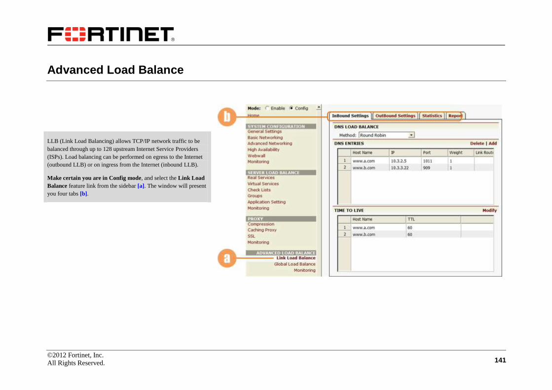
©2012 Fortinet, Inc.
All Rights Reserved. 141
Advanced Load Balance
LLB (Link Load Balancing) allows TCP/IP network traffic to be
balanced through up to 128 upstream Internet Service Providers
(ISPs). Load balancing can be performed on egress to the Internet
(outbound LLB) or on ingress from the Internet (inbound LLB).
Make certain you are in Config mode, and select the Link Load
Balance feature link from the sidebar [a]. The window will present
you four tabs [b].
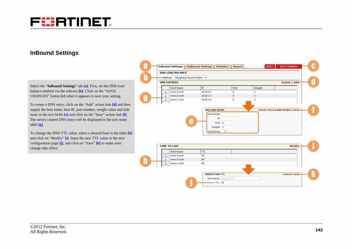
©2012 Fortinet, Inc.
All Rights Reserved. 142
InBound Settings
Select the “InBound Settings” tab [a]. First, set the DNS load
balance method via the selector [b]. Click on the “SAVE
CHANGES” button [c] when it appears to save your setting.
To create a DNS entry, click on the “Add” action link [d] and then
supply the host name, host IP, port number, weight value and link
route in the text fields [e] and click on the “Save” action link [f].
The newly created DNS entry will be displayed in the sort ready
table [g].
To change the DNS TTL value, select a desired host in the table [h]
and click on “Modify” [i]. Input the new TTL value in the new
configuration page [j], and click on “Save” [k] to make your
change take effect.

©2012 Fortinet, Inc.
All Rights Reserved. 143
OutBound Settings
Click on the tab “OutBound Settings” [a]. The configuration
window presents a new configuration page.
Set the Link Load Balance method via the selector [b]. If
“Dynamic Detecting” method is selected, you need to set time
interval and connection count for triggering DD refresh [c]. Use the
check box [d] to enable the LLB health check. Once any change is
made, the “RESET” and “SAVE CHANGES” buttons will appear.
Remember to save any change made by clicking on the “SAVE
CHANGES” button [e].
Select the action link “Add” [f]. A new configuration page is
displayed.
Specify the link name, gateway IP, weight value for the link, set the
health check source IP and bandwidth threshold [g]. At last,
remember to click on the action link “Save” [h] to complete the
configuration. The newly added LLB link route will be displayed in
the table [i].

©2012 Fortinet, Inc.
All Rights Reserved. 144
OutBound Settings (Continue)
In the LLB link list, you can enable a link via the check box [a].
Then, remember to click on “SAVE CHANGES” [b] to save your
configuration.
To modify the settings of a link, double-click it in the table [c], or
select it and click on the action link “Edit” [d]. A new
configuration page will be displayed.
Enable or disable the link via the check box [e]. Then, click on
“Save” [f] to make your setting take effect.
To add an LLB link health checker, click on the action link “Add”
[g]. A new configuration page will appear.
Select the health check type, and supply the required information
[h]. The parameter fields may vary with different health check
types. After finishing the configuration, click on the action link
“Save” [i], and information about the health checker will be
displayed in the sort ready table [j].
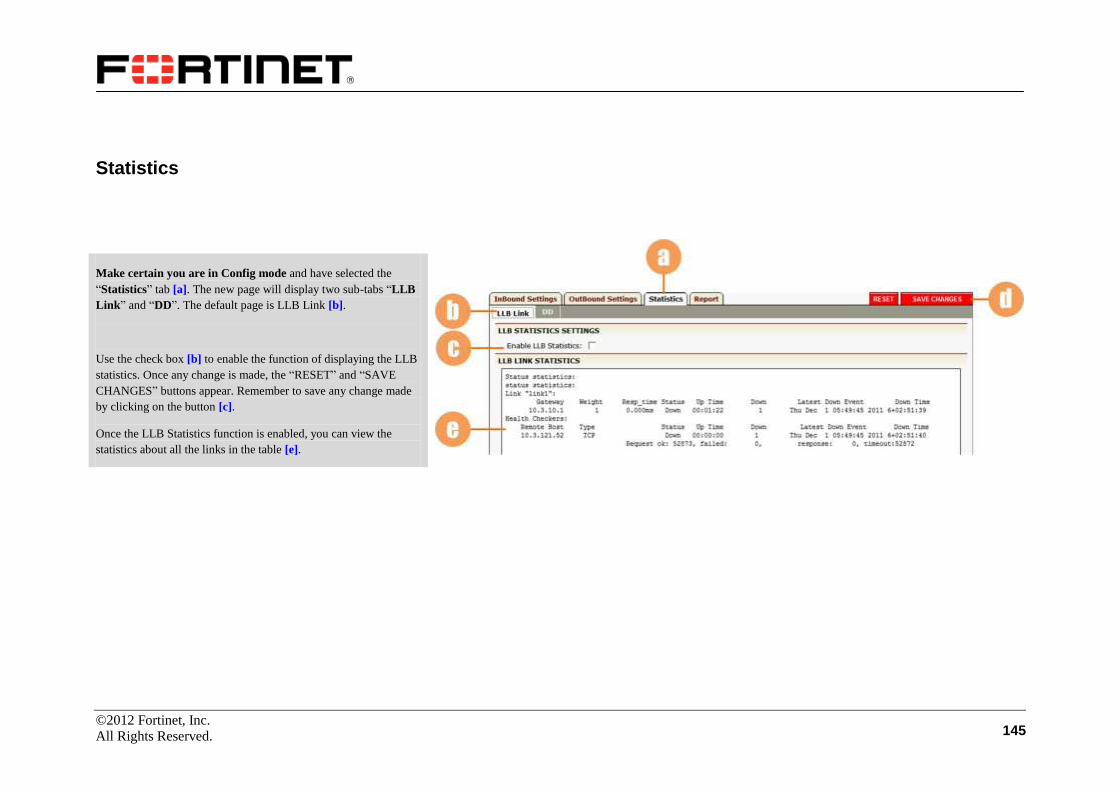
©2012 Fortinet, Inc.
All Rights Reserved. 145
Statistics
Make certain you are in Config mode and have selected the
“Statistics” tab [a]. The new page will display two sub-tabs “LLB
Link” and “DD”. The default page is LLB Link [b].
Use the check box [b] to enable the function of displaying the LLB
statistics. Once any change is made, the “RESET” and “SAVE
CHANGES” buttons appear. Remember to save any change made
by clicking on the button [c].
Once the LLB Statistics function is enabled, you can view the
statistics about all the links in the table [e].
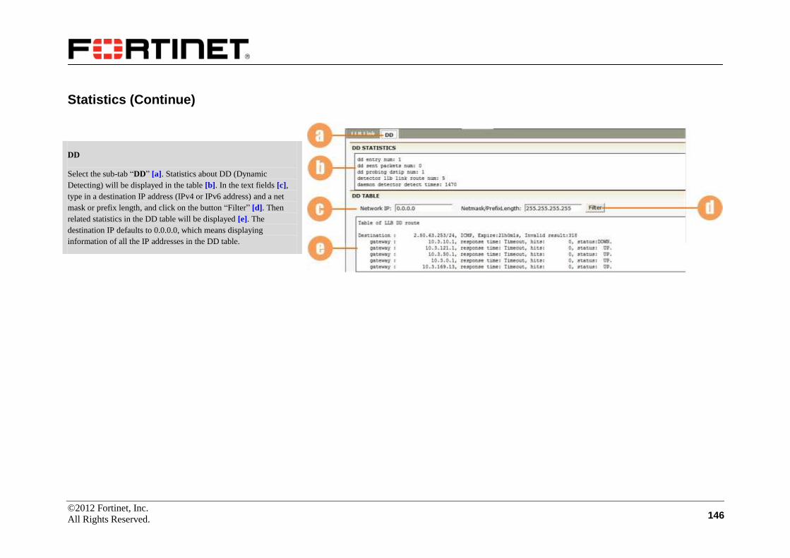
©2012 Fortinet, Inc.
All Rights Reserved. 146
Statistics (Continue)
DD
Select the sub-tab “DD” [a]. Statistics about DD (Dynamic
Detecting) will be displayed in the table [b]. In the text fields [c],
type in a destination IP address (IPv4 or IPv6 address) and a net
mask or prefix length, and click on the button “Filter” [d]. Then
related statistics in the DD table will be displayed [e]. The
destination IP defaults to 0.0.0.0, which means displaying
information of all the IP addresses in the DD table.

©2012 Fortinet, Inc.
All Rights Reserved. 147
Report
Select the “Report” tab [a]. You can view the report under the
Enable mode.
Specify the link name, interval and format of the report via the
selectors [b] and click on the action link “Preview” [c]. Then, you
will be presented with a statistics report of the specified LLB link
in the format and time length you have specified.
Note that the Report page is available only after you have selected
the “Enable LLB Statistics” check box [d] on the Statistics page
[e], and also have enabled the statmon function via the check box
[f] on the Graph Monitoring Setting page under the “Graph
Monitoring” tab [g] (select the Graph feature link under the
Admin Tools feature group [h]).
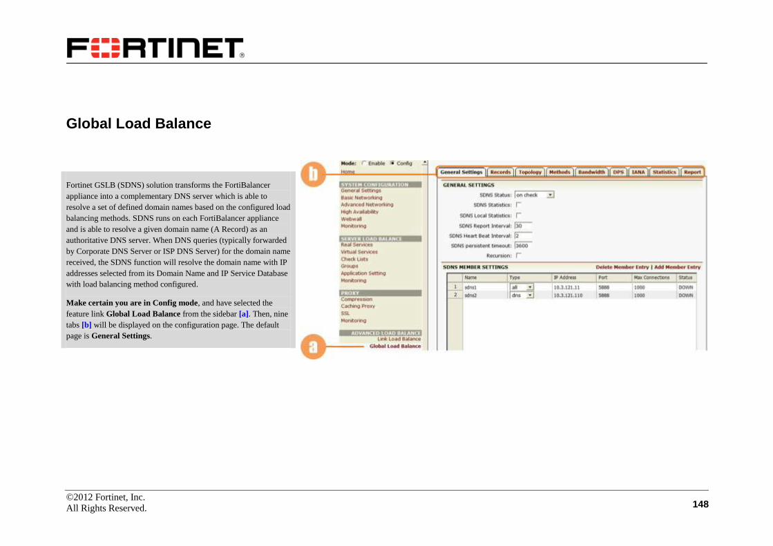
©2012 Fortinet, Inc.
All Rights Reserved. 148
Global Load Balance
Fortinet GSLB (SDNS) solution transforms the FortiBalancer
appliance into a complementary DNS server which is able to
resolve a set of defined domain names based on the configured load
balancing methods. SDNS runs on each FortiBalancer appliance
and is able to resolve a given domain name (A Record) as an
authoritative DNS server. When DNS queries (typically forwarded
by Corporate DNS Server or ISP DNS Server) for the domain name
received, the SDNS function will resolve the domain name with IP
addresses selected from its Domain Name and IP Service Database
with load balancing method configured.
Make certain you are in Config mode, and have selected the
feature link Global Load Balance from the sidebar [a]. Then, nine
tabs [b] will be displayed on the configuration page. The default
page is General Settings.

©2012 Fortinet, Inc.
All Rights Reserved. 149
General Settings
Select the General Settings tab [a]. First, turn on or turn off the
SDNS function via the selector [b]; to turn on the function, you
need to further specify checking (on check) or not checking (on no
check) virtual hosts’ health status.
Next, you can make some basic SDNS settings [c]: enable or
disable the SDNS statistics and local DNS statistics functions,
specify how often HTTP proxy cache servers should report their
local status information, specify how long the FortiBalancer
appliance will wait to send heartbeat messages to all other
members in an SDNS network, specify the SDNS persistent
timeout value, and enable or disable the SDNS recursive query.
Then, click on the “SAVE CHANGES” button [d] to save your
settings.
To add an SDNS member, click on the action link “Add Member
Entry” [e]. In the new configuration page, specify the name, type,
IP address and port number (defaults to 5888) of the SDNS host [f],
and click on “Save” [g]. The newly created SDNS host will be
displayed in the sort ready table [h].
You can also change the SDNS members’ type or set them as local
DNS member in the sort ready table. Remember to click on “SAVE
CHANGES” [d] to save your change.
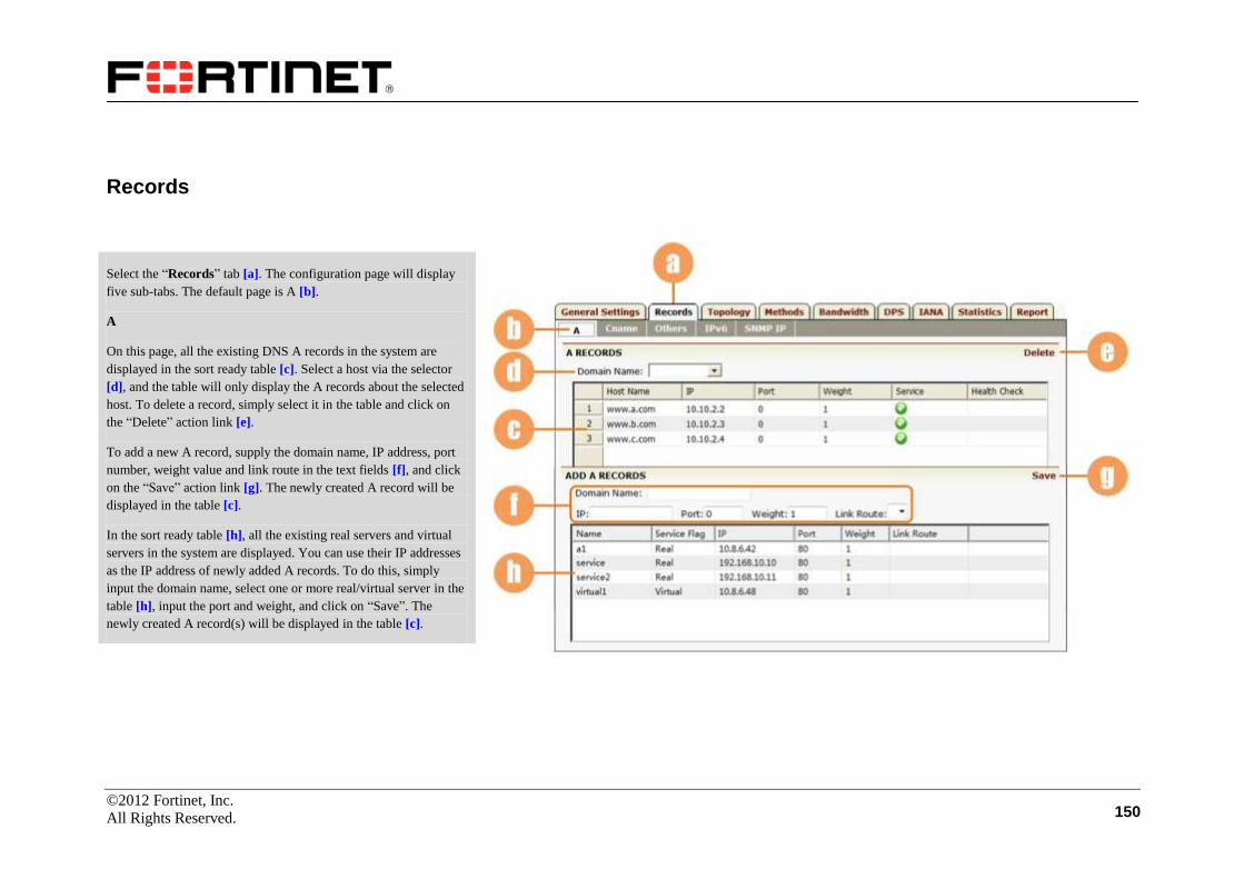
©2012 Fortinet, Inc.
All Rights Reserved. 150
Records
Select the “Records” tab [a]. The configuration page will display
five sub-tabs. The default page is A [b].
A
On this page, all the existing DNS A records in the system are
displayed in the sort ready table [c]. Select a host via the selector
[d], and the table will only display the A records about the selected
host. To delete a record, simply select it in the table and click on
the “Delete” action link [e].
To add a new A record, supply the domain name, IP address, port
number, weight value and link route in the text fields [f], and click
on the “Save” action link [g]. The newly created A record will be
displayed in the table [c].
In the sort ready table [h], all the existing real servers and virtual
servers in the system are displayed. You can use their IP addresses
as the IP address of newly added A records. To do this, simply
input the domain name, select one or more real/virtual server in the
table [h], input the port and weight, and click on “Save”. The
newly created A record(s) will be displayed in the table [c].

©2012 Fortinet, Inc.
All Rights Reserved. 151
Records (Continue)
Cname
Select the sub-tab “Cname” [a]. You can add new CNAME
records for a domain name. Supply the domain name and alias
name in the text fields [b] and click on the action link “Add” [c].
The newly added CNAME records will be displayed in the sort
ready table [d].
To delete an entry in the table, simply select the entry and click on
the “Delete” action link [e].
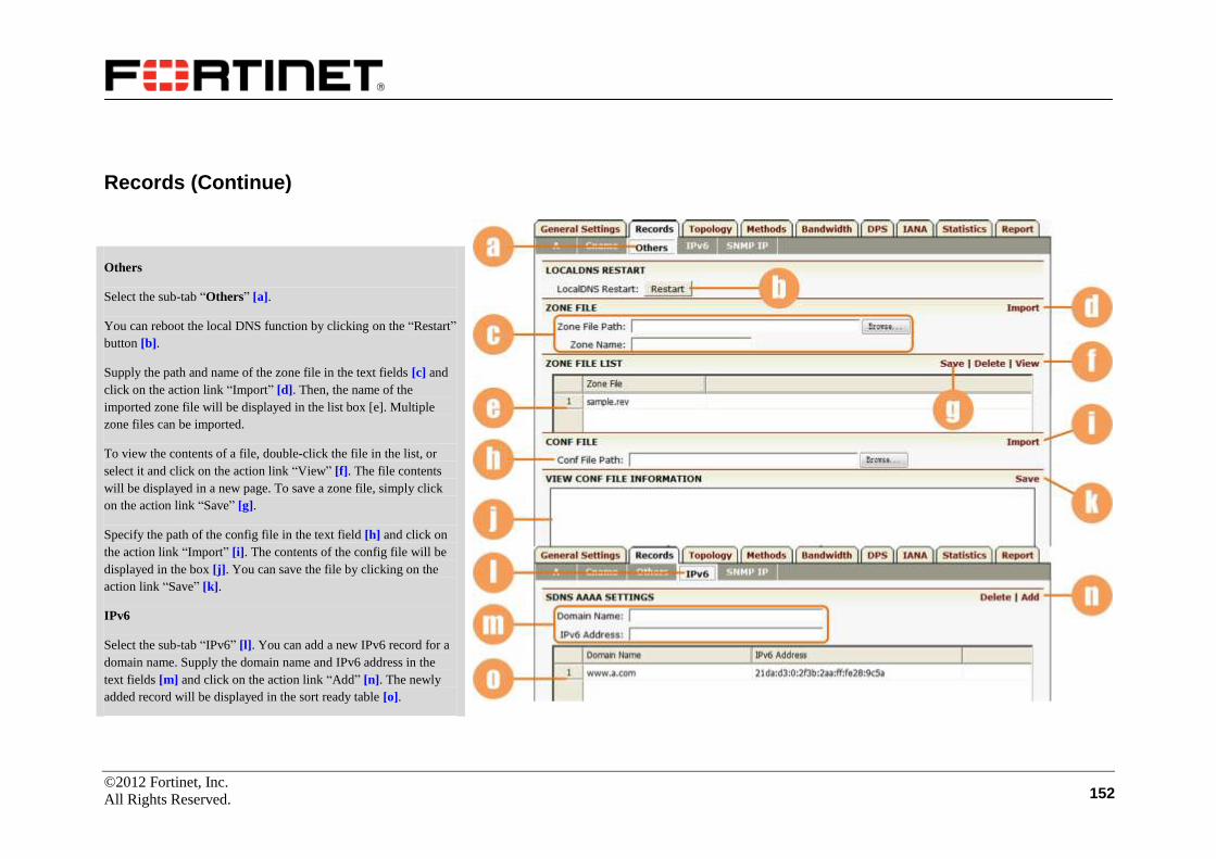
©2012 Fortinet, Inc.
All Rights Reserved. 152
Records (Continue)
Others
Select the sub-tab “Others” [a].
You can reboot the local DNS function by clicking on the “Restart”
button [b].
Supply the path and name of the zone file in the text fields [c] and
click on the action link “Import” [d]. Then, the name of the
imported zone file will be displayed in the list box [e]. Multiple
zone files can be imported.
To view the contents of a file, double-click the file in the list, or
select it and click on the action link “View” [f]. The file contents
will be displayed in a new page. To save a zone file, simply click
on the action link “Save” [g].
Specify the path of the config file in the text field [h] and click on
the action link “Import” [i]. The contents of the config file will be
displayed in the box [j]. You can save the file by clicking on the
action link “Save” [k].
IPv6
Select the sub-tab “IPv6” [l]. You can add a new IPv6 record for a
domain name. Supply the domain name and IPv6 address in the
text fields [m] and click on the action link “Add” [n]. The newly
added record will be displayed in the sort ready table [o].
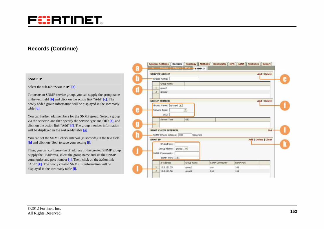
©2012 Fortinet, Inc.
All Rights Reserved. 153
Records (Continue)
SNMP IP
Select the sub-tab “SNMP IP” [a].
To create an SNMP service group, you can supply the group name
in the text field [b] and click on the action link “Add” [c]. The
newly added group information will be displayed in the sort ready
table [d].
You can further add members for the SNMP group. Select a group
via the selector, and then specify the service type and OID [e], and
click on the action link “Add” [f]. The group member information
will be displayed in the sort ready table [g].
You can set the SNMP check interval (in seconds) in the text field
[h] and click on “Set” to save your setting [i].
Then, you can configure the IP address of the created SNMP group.
Supply the IP address, select the group name and set the SNMP
community and port number [j]. Then, click on the action link
“Add” [k]. The newly created SNMP IP information will be
displayed in the sort ready table [l].

©2012 Fortinet, Inc.
All Rights Reserved. 154
Topology
Select the “Topology” tab [a]. The configuration page will display
five sub-tabs. The default page is Site [b].
Site
On the “Site” page, all sites previously configured are displayed in
the sort ready table [c]. To add a new site, click on the action link
“Add Site Entry” [d], supply the site name and weight [e] in the
new configuration page and click on “Save” [f]. Then the newly
created site will be displayed in the sort ready table [c].
You can select a desired site via the radio button to view the
members of the selected site [g]. To edit the site members, click on
the action link “Edit Members of the Site” [h]. Select the members
for the site via the check boxes [i], and click on the “SAVE
CHANGES” button [j] when it appears to make your change take
effect.

©2012 Fortinet, Inc.
All Rights Reserved. 155
Topology (Continue)
Region
Select the sub-tab “Region” [a].
On the “Region” page, all regions previously configured are
displayed in the sort ready table [b]. To add a new region, click on
the action link “Add Region” [c], supply the region name and
weight [d] in the new configuration page and click on “Save” [e].
Then the newly created region will be displayed in the sort ready
table [b].
You can select a desired region via the radio button to view its
child regions [f]. To add a new child region for the selected region,
click on the action link “Add Region Division” [g], and select a
division region via the selector [h]. Then click on the “Save” action
link [i] to make your setting take effect.
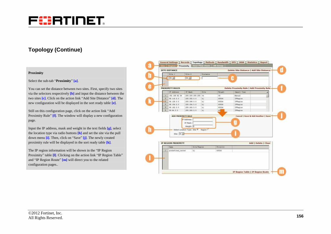
©2012 Fortinet, Inc.
All Rights Reserved. 156
Topology (Continue)
Proximity
Select the sub-tab “Proximity” [a].
You can set the distance between two sites. First, specify two sites
via the selectors respectively [b] and input the distance between the
two sites [c]. Click on the action link “Add Site Distance” [d]. The
new configuration will be displayed in the sort ready table [e].
Still on this configuration page, click on the action link “Add
Proximity Rule” [f]. The window will display a new configuration
page.
Input the IP address, mask and weight in the text fields [g], select
the location type via radio buttons [h] and set the site via the pull
down menu [i]. Then, click on “Save” [j]. The newly created
proximity rule will be displayed in the sort ready table [k].
The IP region information will be shown in the “IP Region
Proximity” table [l]. Clicking on the action link “IP Region Table”
and “IP Region Route” [m] will direct you to the related
configuration pages..

©2012 Fortinet, Inc.
All Rights Reserved. 157
Topology (Continue)
Over Flow Chain
Select the sub-tab “Over Flow Chain” [a].
On this page, all overflow chains previously configured are
displayed in the sort ready table [b]. To add a new chain, click on
the action link “Add Overflow Chain” [c], supply the chain name
[d] in the new configuration page and click on “Save” [e]. Then the
newly created chain will be displayed in the sort ready table [b].
You can select a desired chain via the radio button to view the
members of the chain [f]. To edit the chain members, click on the
action link “Edit Members of the Chain” [g]. Select the members
for the chain via the check boxes [h], and click on the “SAVE
CHANGES” button [i] when it appears to make your change take
effect.

©2012 Fortinet, Inc.
All Rights Reserved. 158
Topology (Continue)
DR Group
Select the sub-tab “DR Group” [a].
Enter the DR (disaster recovery) group name and the domain name
that requires disaster recovery in the text fields [b], and click on the
action link “Add DrGroup” [c]. The newly added group
information will be displayed in the sort ready table [d].
In the table, you can switch on/off a DR group via the check box
[e]. Remember to click on the “SAVE CHANGES” button [f] when
it appears to save your change.
Select a desired DR group via the radio button [g], and you can see
the list of the sites in the group [h]. You can further add these sites
into a primary DR group or a standby DR group. To do this, select
“Primary” or “Standby” via the selector [i], and specify the sites to
be added into the group via the check boxes [j]. Then, click on the
“Save Group Site Settings” action link [k] to save your changes.
You can disable the primary group or standby group via the check
boxes [l].
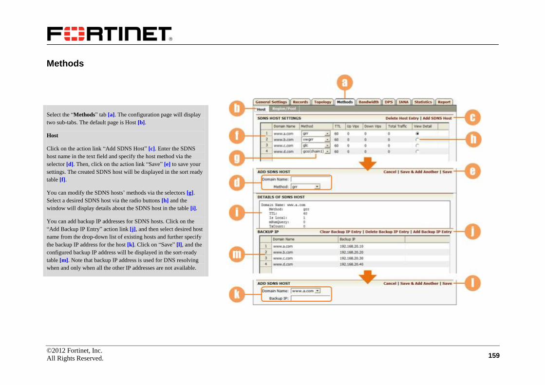
©2012 Fortinet, Inc.
All Rights Reserved. 159
Methods
Select the “Methods” tab [a]. The configuration page will display
two sub-tabs. The default page is Host [b].
Host
Click on the action link “Add SDNS Host” [c]. Enter the SDNS
host name in the text field and specify the host method via the
selector [d]. Then, click on the action link “Save” [e] to save your
settings. The created SDNS host will be displayed in the sort ready
table [f].
You can modify the SDNS hosts’ methods via the selectors [g].
Select a desired SDNS host via the radio buttons [h] and the
window will display details about the SDNS host in the table [i].
You can add backup IP addresses for SDNS hosts. Click on the
“Add Backup IP Entry” action link [j], and then select desired host
name from the drop-down list of existing hosts and further specify
the backup IP address for the host [k]. Click on “Save” [l], and the
configured backup IP address will be displayed in the sort-ready
table [m]. Note that backup IP address is used for DNS resolving
when and only when all the other IP addresses are not available.

©2012 Fortinet, Inc.
All Rights Reserved. 160
Methods (Continue)
Region/Pool
Select the sub-tab “Region/Pool” [a].
Click on the action link “Add Pool Entry” [b]. A new configuration
page will appear. Select to add an SDNS pool or an SDNS rule via
the selector [c], and the parameter fields will vary with your
selection. The following will introduce how to add an SDNS pool
and how to add an SDNS rule.
To add an SDNS pool, specify a host and select a configured region
or site to be the pool via the selectors respectively [d], and set the
pool type (A or CNAME) via the selector [e].
For type “A”, you need to set the pool’s method [f]. For method rr,
wrr or snmp, you need to enter the number of returned IPs [g]. For
method ipo, you need to enable or disable the SDNS pool ipo
preemption [h] and further enter the number of returned IPs.
Then, click on “Save” [i]. The newly added pool will be displayed
in the sort ready table [j].
To modify the SDNS pool settings, you can select an entry and
select the radio button [k], or double-click the entry. The window
will display a new configuration page.

©2012 Fortinet, Inc.
All Rights Reserved. 161
Methods (Continue)
Region/Pool (Continue)
In this new page, you can modify the pool type via the selector [a].
If A is selected, you need to set the method [b]. If you select the
“snmp” method, you need to further set the order type (ascending
or descending), service type and weight value [c]. Click on the
action link “Save” [d] to save your configuration.
If the “ipo” method is selected and if the SDNS pool ipo
preemption is disabled, you can manually preempt [e].
You can further add pool resources.
For pool type “A”, you need to specify the record type (A or
AAAA) via the selector [f]: if “A” is selected, you need to input the
IP address and priority in the text fields [g]; if “AAAA” is selected,
you need to input the IPv6 address and priority in the text fields
[h].
For pool type “CNAME”, you need to input the IP address [i].
Click on the action link “Add” [j]. The newly added pool resource
will be displayed in the sort ready table [k].

©2012 Fortinet, Inc.
All Rights Reserved. 162
Methods (Continue)
Region/Pool (Continue)
To add an SDNS rule, click on the “Add Rule Entry” action link
[a]. In the new configuration page, select “rule” via the selector
[b], input the rule name in the text field and select a configured
region or site via the selector [c]. Set the method via the selector
[d] and enter the number of returned records in the text field [e].
Click on the “Save” action link [f]. The newly added rule will be
displayed in the sort ready table [g].
In the table, you can select the radio button [h] or double-click an
entry The window will display a new configuration page.

©2012 Fortinet, Inc.
All Rights Reserved. 163
Methods (Continue)
Region/Pool (Continue)
In this new page, you can modify the method via the selector [a],
and set the number of returned records in the text field [b]. Then,
click on the action link “Save” [c] to save your configuration.
You can further add rule resources. Input the IP address and weight
properly in the text fields [d] and click on the action link “Add” [e].
Then the newly added information will be displayed in the sort
ready table [f].
You can further specify the hosts that use the created rule. Specify
the desired hosts via the check boxes [g] and click on the “SAVE
CHANGES” button [h] when it appears to make your settings take
effect.

©2012 Fortinet, Inc.
All Rights Reserved. 164
Bandwidth
Select the “Bandwidth” tab [a]. The configuration page will
display five sub-tabs. The default page is Region [b].
Region
On the new page, all regions configured previously are displayed in
the sort ready table [c]. To specify the maximum bandwidth of a
region, double-click the entry under the “Limit” column and input
the value in the text field [d]. You can also set the mode of each
region via the selector [e]. Remember to click on the “SAVE
CHANGES” button [f] when it appears to save your configuration.
Site
Select the sub-tab “Site” [g]. Follow the same steps with the region
band settings to set the bandwidth for sites.
Member
Select the sub-tab “Member” [h]. Follow the same steps with the
region band settings to set the bandwidth for members.

©2012 Fortinet, Inc.
All Rights Reserved. 165
Bandwidth (Continue)
Host
Select the sub-tab “Host” [a]. Enter the domain name and the
maximum bandwidth in the text fields [b]. Specify the bandwidth
mode via the selector [c]. Then, click on the action link “Add Band
Entry” [d], and the information will be displayed in the sort ready
table [e].
You can modify the maximum bandwidth by double-clicking on it
under the “Limit” column [f]. You can also change the mode via
the selector [g].
IP
Select the “IP” sub-tab [h]. Enter the IP address and the maximum
bandwidth of the IP address in the text fields [i]. Set the bandwidth
mode via the selector [j]. Then, click on the action link “Add Band
Entry” [k], and the configured information will be displayed in the
sort ready table [l].
To modify the IP bandwidth and mode, follow the same way with
the host bandwidth modification.
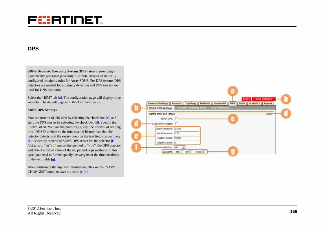
©2012 Fortinet, Inc.
All Rights Reserved. 166
DPS
SDNS Dynamic Proximity System (DPS) aims at providing a
dynamically generated proximity rule table, instead of statically
configured proximity rules for Array SDNS. For DPS feature, DPS
detectors are needed for proximity detection and DPS servers are
used for DNS resolution.
Select the “DPS” tab [a]. The configuration page will display three
sub-tabs. The default page is SDNS DPS Settings [b].
SDNS DPS Settings
You can turn on SDNS DPS by selecting the check box [c], and
start the DPS master by selecting the check box [d]. Specify the
interval of SDNS dynamic proximity query, the interval of sending
local DNS IP addresses, the time span of history data that the
detector detects, and the expiry count in the text fields respectively
[e]. Select the method of SDNS DPS server via the selector [f]
(defaults to “rtt”). If you set the method to “mix”, the DPS detector
will detect a mixed value of the rtt, plr and hops methods. In this
case, you need to further specify the weights of the three methods
in the text fields [g].
After confirming the inputted information, click on the “SAVE
CHANGES” button to save the settings [h].

©2012 Fortinet, Inc.
All Rights Reserved. 167
DPS (Continue)
SDNS DPS Settings (Continue)
To add a DPS server into the DPS member list, enter the IP address
of the DPS server in the text field [a] and click on the “Add” action
link [b]. The new member will be displayed in the sort ready table
[c]. You can delete a member from the list or clear all members by
clicking on the desired action link [d].
To add an SDNS DPS detector, you can click on the action link
“Add” [e], and the configuration window will display a new page.
Specify the site (must have been defined in SDNS configuration),
the IP address of the detector, port number (defaults to 44544) and
detect interval in the text fields [f]. Click on the “Save” action link
[g], and the settings will be displayed in the sort ready table [h].
You can select to delete a detector, edit detector configuration or
clear all detectors’ configuration by clicking on the desired action
link [i].

©2012 Fortinet, Inc.
All Rights Reserved. 168
DPS (Continue)
Dynamic Proximity Rules
Select the “Dynamic Proximity Rules” sub tab [a]. On this page,
all the dynamic proximity statistics generated based on the
detection results will be displayed in the table [b].
To export the dynamic proximity statistics, you can first select the
sort standard and specify to export the statistics in ascending or
descending order [c], and then click on the “Export” action link [d].
You can export the dynamic proximity rules via three methods:
File, SCP and TFTP. For File method, select the “File” radio button
and input the file name in the text field [e]; for SCP method, select
the “SCP” radio button and input required information in the text
fields [f]; for TFTP method, select the “TFTP” radio button and
input required information in the text fields [g].
After confirming the inputted information, click on the “Export”
action link [h] to start exporting.

©2012 Fortinet, Inc.
All Rights Reserved. 169
DPS (Continue)
Local Detectors
Select the “Local Detectors” sub tab [a].
To add and SDNS DPS local detectors, first specify a name for the
local detector [b]. Then, enter the IP address, interface name, detect
port number, report port number and detect timeout value in the
text fields [c]. After confirming the inputted information, click on
the action link [d]. The configured information of the local
detectors will be displayed in the table below [e].
To delete a local detector or clear all local detectors, you can click
on the desired action link [f].
You can view the version information of the SNDS DPS local
detector in the table [g].
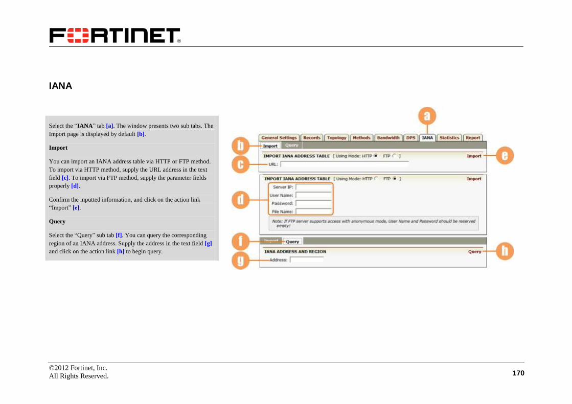
©2012 Fortinet, Inc.
All Rights Reserved. 170
IANA
Select the “IANA” tab [a]. The window presents two sub tabs. The
Import page is displayed by default [b].
Import
You can import an IANA address table via HTTP or FTP method.
To import via HTTP method, supply the URL address in the text
field [c]. To import via FTP method, supply the parameter fields
properly [d].
Confirm the inputted information, and click on the action link
“Import” [e].
Query
Select the “Query” sub tab [f]. You can query the corresponding
region of an IANA address. Supply the address in the text field [g]
and click on the action link [h] to begin query.
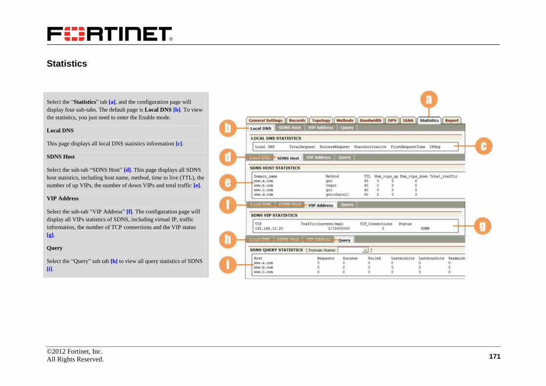
©2012 Fortinet, Inc.
All Rights Reserved. 171
Statistics
Select the “Statistics” tab [a], and the configuration page will
display four sub-tabs. The default page is Local DNS [b]. To view
the statistics, you just need to enter the Enable mode.
Local DNS
This page displays all local DNS statistics information [c].
SDNS Host
Select the sub-tab “SDNS Host” [d]. This page displays all SDNS
host statistics, including host name, method, time to live (TTL), the
number of up VIPs, the number of down VIPs and total traffic [e].
VIP Address
Select the sub-tab “VIP Address” [f]. The configuration page will
display all VIPs statistics of SDNS, including virtual IP, traffic
information, the number of TCP connections and the VIP status
[g].
Query
Select the “Query” sub tab [h] to view all query statistics of SDNS
[i].

©2012 Fortinet, Inc.
All Rights Reserved. 172
Report
Select the “Report” tab [a]. To view the report, you just need to
enter the Enable mode.
Specify the interval of the report via the selector [b] and select the
desired report format [c]. Click on the action link “Preview” [d].
Then, you will be presented with an SDNS Statistics Report file in
the format you have specified.
Note that the contents on the Report page are available only after
you have made the following configurations.
Go to the General Settings page [e], and enable the SDNS
Statistics and SDNS Local Statistics functions [f].
Select the Graph feature link [g] under the Admin Tools
feature group, and go to the Graph Monitoring Setting page
under the “Graph Monitoring” tab [h]. Then, enable the
statmon function via the check box [i].

©2012 Fortinet, Inc.
All Rights Reserved. 173
Monitoring
FortiBalancer appliance allows users to monitor real-time SDNS query and pool SNMP statistics.
SDNS
To use this feature, you just need to enter the Enable mode.
Select the feature link Monitoring from the sidebar [a].
Select the “SDNS” tab [b], and the window will display the
monitoring information about SDNS queries in the table [c].
Pool SNMP Statistics
Select the “Pool SNMP Statistics” tab [d]. The window will
display the monitoring information about pool SNMP statistics in
the table [e].

©2012 Fortinet, Inc.
All Rights Reserved. 174
Admin Tools
System Management
In this section, we will discuss various configuration management functions available for the FortiBalancer appliance.
System Info
Make certain you are in Config mode and have selected the
System Management feature link from the sidebar [a]. The
configuration window will present a page with five navigational
tabs [b].
Under the “System Info” tab, there are three sub tabs: Version,
Memory and Statistics. By default, the Version page is displayed
[c].
Version
On this page, the window displays the current running version and
related information of the FortiBalancer powering the
FortiBalancer appliance [d].

©2012 Fortinet, Inc.
All Rights Reserved. 175
System Info (Continue)
Memory
Select the “Memory” sub tab [a], and the window will display all
data about current memory usage in the box [b].
Statistics
Select the “Statistics” sub tab [c], and the window will display all
information about current configuration in the box [d].
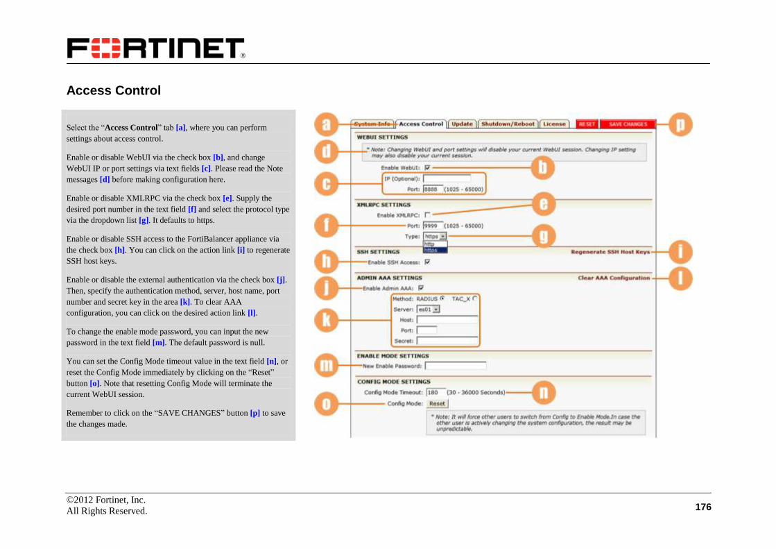
©2012 Fortinet, Inc.
All Rights Reserved. 176
Access Control
Select the “Access Control” tab [a], where you can perform
settings about access control.
Enable or disable WebUI via the check box [b], and change
WebUI IP or port settings via text fields [c]. Please read the Note
messages [d] before making configuration here.
Enable or disable XMLRPC via the check box [e]. Supply the
desired port number in the text field [f] and select the protocol type
via the dropdown list [g]. It defaults to https.
Enable or disable SSH access to the FortiBalancer appliance via
the check box [h]. You can click on the action link [i] to regenerate
SSH host keys.
Enable or disable the external authentication via the check box [j].
Then, specify the authentication method, server, host name, port
number and secret key in the area [k]. To clear AAA
configuration, you can click on the desired action link [l].
To change the enable mode password, you can input the new
password in the text field [m]. The default password is null.
You can set the Config Mode timeout value in the text field [n], or
reset the Config Mode immediately by clicking on the “Reset”
button [o]. Note that resetting Config Mode will terminate the
current WebUI session.
Remember to click on the “SAVE CHANGES” button [p] to save
the changes made.

©2012 Fortinet, Inc.
All Rights Reserved. 177
Update
Select the “Update” tab [a], and the window will present a new
configuration page. You can update the system by using a local
host file or a URL. To update via a local host file, select the radio
button and specify the file path [b] (a browse button is present to
help locate files). To update via a URL, select the radio button and
specify the URL [c]. Once the file path is located or the URL path
is specified, click on the “Apply Update” action link [d].

©2012 Fortinet, Inc.
All Rights Reserved. 178
Shutdown/Reboot
License
Select the “Shutdown/Reboot” tab [a], and the window will
present a new configuration page. You can reboot the system by
clicking on the “Reboot NOW” button [b], or shut down the system
by clicking on the “Shut down NOW” button [c]. The shutdown
mode (“halt” means the system stops but the appliance stays in the
poweron state; “poweroff” means the system stops and the
appliance powers off.), can be specified via the dropdown list [d],
and it defaults to “poweroff”. The check box [e] can be selected to
fall back to the previous software version on the next reboot.
Remember to click on the “SAVE CHANGES” button [f] when it
appears to save your configuration.
Select the “License” tab [a], and a new configuration page will be
displayed. In the text field [b], the current license for the
FortiBalancer appliance is displayed. If you want to replace the
license with a new license, input the new one in the field [b] and
click on the desired action link [c].

©2012 Fortinet, Inc.
All Rights Reserved. 179
Config Management
In this section, we will discuss the configuration management functions available for the FortiBalancer appliance.
View
Make certain you are in Config mode and have selected the
Config Management feature link from the sidebar [a]. The
window will present a configuration page with seven navigational
tabs. The View page is displayed by default [b].
Under the “View” tab, there are three sub tabs: Running Config,
Startup Config and Saved File [c].
Running Config
The Running Config page displays information about the current
running configurations [d].
Startup Config
Select the “Startup Config” sub tab [e], and the configuration
window will display the startup configuration information [f].
Saved File
Select the “Saved File” sub tab [g], and the configuration window
will display all configuration files currently saved in the sort ready
table [h]. Double-click a file entry to view the file details.
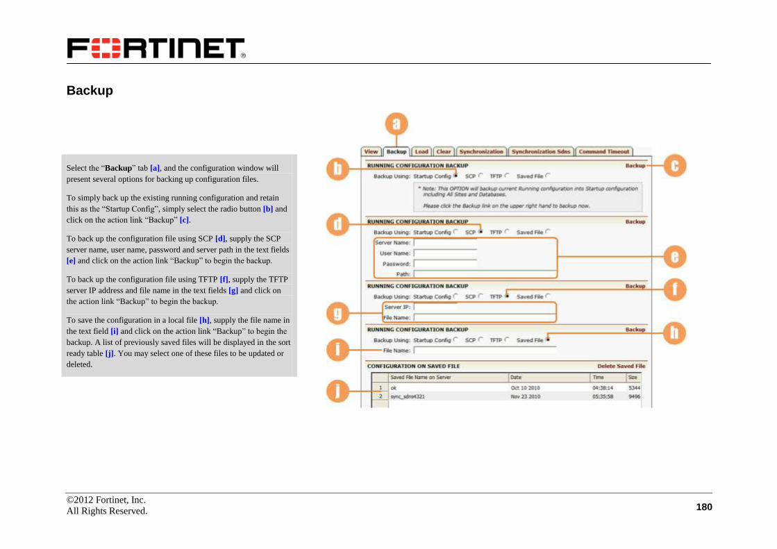
©2012 Fortinet, Inc.
All Rights Reserved. 180
Backup
Select the “Backup” tab [a], and the configuration window will
present several options for backing up configuration files.
To simply back up the existing running configuration and retain
this as the “Startup Config”, simply select the radio button [b] and
click on the action link “Backup” [c].
To back up the configuration file using SCP [d], supply the SCP
server name, user name, password and server path in the text fields
[e] and click on the action link “Backup” to begin the backup.
To back up the configuration file using TFTP [f], supply the TFTP
server IP address and file name in the text fields [g] and click on
the action link “Backup” to begin the backup.
To save the configuration in a local file [h], supply the file name in
the text field [i] and click on the action link “Backup” to begin the
backup. A list of previously saved files will be displayed in the sort
ready table [j]. You may select one of these files to be updated or
deleted.

©2012 Fortinet, Inc.
All Rights Reserved. 181
Load
Select the “Load” tab [a], and the configuration window will
present several options for loading configuration files.
To load the last running configuration, select the “Startup Config”
radio button [b] and click on the action link “Load” [c].
To load a file from an SCP server [d], supply the SCP server name,
user name, password and server path in the text fields [e] and click
on the action link “Load” to begin loading.
To load a file using TFTP [f], supply the TFTP server IP address
and file name in the text fields [g] and click on the action link
“Load” to begin loading.
To load a file from an HTTP server [h], supply the HTTP URL in
the text field [i] and click on the action link “Load”.
To load a locally saved file [j], select the file name from a list of
previously saved files [k] and click on the action link “Load”.
To load a file from a network location [l], supply the file name in
the field [m] or click on the “Browse” button to locate the file.
Then click on the action link “Load”.

©2012 Fortinet, Inc.
All Rights Reserved. 182
Clear
Caution should be taken when clearing configurations from the
FortiBalancer appliance. Make certain that you only clear those
configurations you wish to clear. If you have any questions with
clearing a running or saved configuration, please contact Fortinet
Customer Support.
Select the “Clear” tab [a] and the configuration window will
present four buttons for clearing various configurations.
To reset the primary networking functions of the FortiBalancer
appliance to the default, including all access lists and groups, IP
addresses, clustering and synchronization, click on the “Clear
NOW” button [b] for primary configuration.
To reset those secondary network functions of the configuration
such as WebUI, NAT, proxy settings, SNMP and logging, click on
the “Clear NOW” button for secondary configuration [c].
To clear and delete all locally saved configuration files, except for
the default startup file, click on the “Clear NOW” button for entire
configuration [d].
To reset the FortiBalancer appliance to factory default allowing for
console connectivity only, click on the “Reset NOW” button for
factory default configuration [e].
Read the notes [f] carefully before clearing.

©2012 Fortinet, Inc.
All Rights Reserved. 183
Synchronization
The synchronization feature allows you to transfer configuration
information among separate FortiBalancer appliances (referred to
as Peers or Nodes) on the same network. Using configuration
synchronization, you can also setup an active-standby
configuration for failover support. The basic configuration must be
completed before configuring the virtual clustering functionality.
Nodes/Peers
Make certain you have selected the “Synchronization” tab [a], and
the window presents five sub tabs. The Nodes/Peers page is
displayed by default [b]. Here, all peers previously configured will
be displayed in the sort ready table [c]. The first step with
synchronization is to define the name and IP address for each peer.
To do this, you can click on the action link “Add Node/Peer Entry”
[d].
In the new configuration window, supply the node/peer name and
IP address in the texts fields [e] and click on the “Save” action link
[f].
All newly added peers will be displayed in the sort ready table [c].

©2012 Fortinet, Inc.
All Rights Reserved. 184
Synchronization (Continue)
Tasks
Select the “Tasks” sub tab [a]. The configuration window will
display all configured peers in the table under “Configuration
Synchronization” [b] where all individual FortiBalancer appliances
share the same configuration, and also in the table under
“Synchronization Rollback” [c], where you can pull a specific
FortiBalancer appliance back out of a clustered group and rollback
the configuration to the pre-synchronized status (refer to the
following “Synchronization Rollback” section).
Configuration Synchronization: This feature allows you to either
“push” a configuration onto other FortiBalancer appliances in the
network via the “TO” radio button [d] or “pull” a configuration
from a specific appliance and place the configuration on the
appliance being setup via the “FROM” radio button [e]. Note that
you may “push” a configuration onto all existing appliances, but
you can only “pull’ a configuration from one appliance at a time.
Once you have selected the appliances to synchronize, click on the
link [f].
Synchronization Rollback: To reset to a previously synchronized
configuration that was received from another peer appliance on the
network, select the “LOCAL” radio button [g], select the peer
appliance that originated the configuration from the list [c] and
click on the “Rollback” action link [i]. To reset a peer that received
the configuration from the current appliance, select “REMOTE”
[h], specify the destination appliance from the list [c] and click on
the action link [i].

©2012 Fortinet, Inc.
All Rights Reserved. 185
Synchronization (Continue)
Results
Select the “Results” sub tab [a], and the configured peers are
displayed in the sort ready table [b]. You can view the
synchronization results of a peer by double-clicking on it in the
table or selecting it and clicking on the action link “View Synch
Summary” [c]. Then, the results will be displayed in the table
below [d].
Differences
Select the “Differences” sub tab [e], and all configured peers are
displayed in the sort ready table [f]. Double-click a desired peer to
view the configuration differences between the selected remote
peer FortiBalancer appliance and the appliance which you are
currently synchronizing from.
History
Select the “History” sub tab [g], and the page will display all
synchronization events related to the current FortiBalancer
appliance being configured in the box [h].

©2012 Fortinet, Inc.
All Rights Reserved. 186
Synchronization Sdns
The SDNS Synchronization feature of the FortiBalancer appliance
allows administrators to synchronize SDNS configurations and
BIND 9 zone files except SDNS member configurations from an
FortiBalancer appliance to its peers.
Select the “Synchronization Sdns” tab [a], and the window
presents two sub tabs.
Nodes/Peers
Select the “Nodes/Peers” sub tab [b]. All peers previously
configured will be displayed in the sort ready table [c]. The first
step with synchronization is to define the name and IP address for
each peer. To do this, you can click on the action link “Add
Node/Peer Entry” [d]. In the new configuration window, supply the
node/peer name and IP address in the texts fields [e] and click on
the “Save” action link [f]. The newly added peers will be displayed
in the sort ready table [c].
Tasks
Select the “Tasks” sub tab [g]. The configuration window will
display all configured peers in the table under “Configuration
Synchronization” [h]. Select a desired node or peer in the table and
click on the “Synchronization” action link [i] to begin
synchronizing.
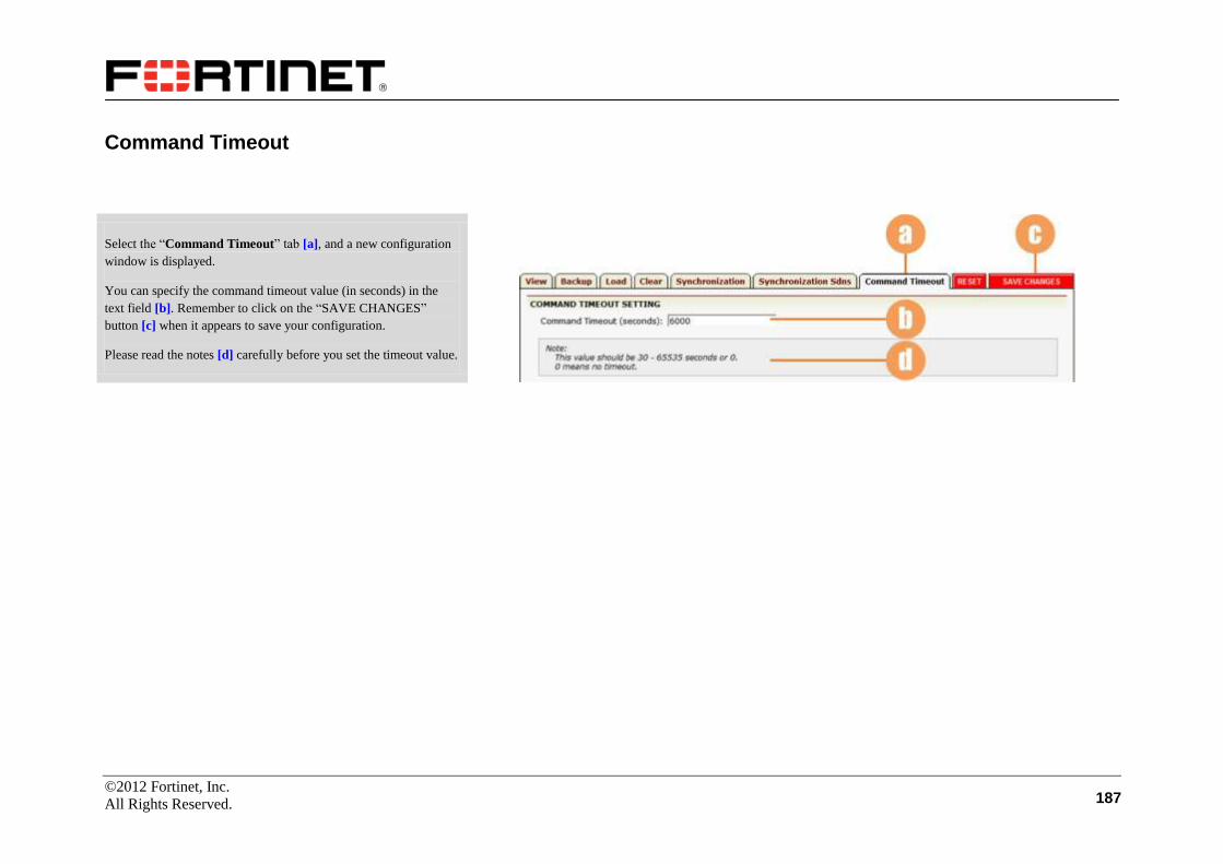
©2012 Fortinet, Inc.
All Rights Reserved. 187
Command Timeout
Select the “Command Timeout” tab [a], and a new configuration
window is displayed.
You can specify the command timeout value (in seconds) in the
text field [b]. Remember to click on the “SAVE CHANGES”
button [c] when it appears to save your configuration.
Please read the notes [d] carefully before you set the timeout value.

©2012 Fortinet, Inc.
All Rights Reserved. 188
Graph
Make certain you are in Config mode and have selected the Graph feature link from the sidebar [a]. The configuration window presents four tabs [b].
Logging
Under the “Logging” tab, there are five sub tabs [c]. The General
page is displayed by default [d].
General
Enable the logging feature via the check box [e], and enable the
timestamp feature for log entries via the check box [f]. Set the
facility from LOCAL0 to LOCAL7 via the selector [g], and set the
log level (any message below the specified level will be ignored)
via the selector [h]. Set the source port in the text field [i].
You can reset the log setting by clicking on the “Clear NOW”
button [j]. Note that this operation will set log setting to the default.
You can generate a test log message by clicking on the “Generate
NOW” button [k].
You can view the log list text file or HTML file by clicking on the
“View” buttons [l] and [m] respectively.
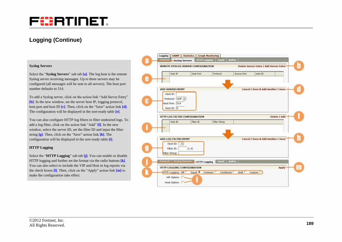
©2012 Fortinet, Inc.
All Rights Reserved. 189
Logging (Continue)
Syslog Servers
Select the “Syslog Servers” sub tab [a]. The log host is the remote
Syslog server receiving messages. Up to three servers may be
configured (all messages will be sent to all servers). The host port
number defaults to 514.
To add a Syslog server, click on the action link “Add Server Entry”
[b]. In the new window, set the server host IP, logging protocol,
host port and host ID [c]. Then, click on the “Save” action link [d].
The configuration will be displayed in the sort-ready table [e].
You can also configure HTTP log filters to filter undesired logs. To
add a log filter, click on the action link “Add” [f]. In the new
window, select the server ID, set the filter ID and input the filter
string [g]. Then, click on the “Save” action link [h]. The
configuration will be displayed in the sort-ready table [i].
HTTP Logging
Select the “HTTP Logging” sub tab [j]. You can enable or disable
HTTP logging and further set the format via the radio buttons [k].
You can also select to include the VIP and Host in log reports via
the check boxes [l]. Then, click on the “Apply” action link [m] to
make the configuration take effect.

©2012 Fortinet, Inc.
All Rights Reserved. 190
Logging (Continue)
Select the “Email” sub tab [a], and a new configuration page is
displayed. You can configure an alert email to report issues. To add
an email alert, click on the action link “Add Email Alert Entry” [b]
and a new configuration page appears.
Set the log/entry ID in the text field [c], define the message that
accompanies the log alert [d] as a message of importance, supply
the email address of the recipient [e] and the interval between
sending reports (in minutes) [f], and specify the report type via the
selector [g]. The report can be either a “data” report or a “count”
(number of incidents) report. At last, click on the desired action
link [h] to complete configuration.
You can set the “From” header in the mail being sent out via the
text field [i], and set the value of the hostname from which the mail
is recorded as sent via the text field [j]. Remember to click on
“SAVE CHANGES” [k] when it appears to save your
configuration.
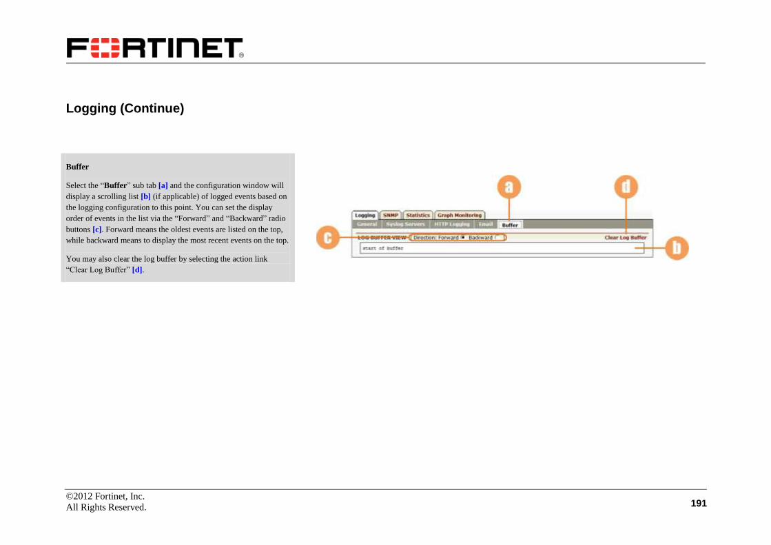
©2012 Fortinet, Inc.
All Rights Reserved. 191
Logging (Continue)
Buffer
Select the “Buffer” sub tab [a] and the configuration window will
display a scrolling list [b] (if applicable) of logged events based on
the logging configuration to this point. You can set the display
order of events in the list via the “Forward” and “Backward” radio
buttons [c]. Forward means the oldest events are listed on the top,
while backward means to display the most recent events on the top.
You may also clear the log buffer by selecting the action link
“Clear Log Buffer” [d].

©2012 Fortinet, Inc.
All Rights Reserved. 192
SNMP
SNMP (Simple Network Management Protocol) is a widely used
protocol for network monitoring and control. Data are passed from
SNMP agents, which are hardware and/or software processes
reporting activity on each network device to the workstation
console which oversees the network. At most three SNMP hosts
can be configured. Note that SNMP traps must be enabled to view
graphs on the Array Flight Deck.
Make certain that you are in Config mode and have selected the
“SNMP” tab [a]. The window presents five sub tabs. By default,
the General page is displayed [b].
General
Enable/disable the SNMP feature via the selector [c]. You can
enable the FortiBalancer appliance to send generic and enterprise
traps via the “Enable Trap” check box, and enable access control
based on the source IP of an SNMP client via the “Enable IP”
check box [d]. Define a community string [e] (at most 32
characters) to act as a password to limit or control access from the
NMS to the agent. Specify the contact person and FortiBalancer
appliance location in the text fields [f] (at most 128 characters for
each). Click on the “SAVE CHANGES” button [g] when it appears
to save changes made.
Note: For the sake of security, it is strongly recommended to
modify the default SNMP community string to avoid possible
system information interception.
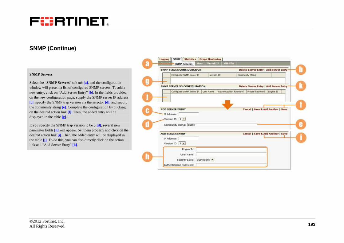
©2012 Fortinet, Inc.
All Rights Reserved. 193
SNMP (Continue)
SNMP Servers
Select the “SNMP Servers” sub tab [a], and the configuration
window will present a list of configured SNMP servers. To add a
new entry, click on “Add Server Entry” [b]. In the fields provided
on the new configuration page, supply the SNMP server IP address
[c], specify the SNMP trap version via the selector [d], and supply
the community string [e]. Complete the configuration by clicking
on the desired action link [f]. Then, the added entry will be
displayed in the table [g].
If you specify the SNMP trap version to be 3 [d], several new
parameter fields [h] will appear. Set them properly and click on the
desired action link [i]. Then, the added entry will be displayed in
the table [j]. To do this, you can also directly click on the action
link add “Add Server Entry” [k].
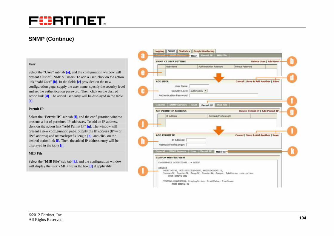
©2012 Fortinet, Inc.
All Rights Reserved. 194
SNMP (Continue)
User
Select the “User” sub tab [a], and the configuration window will
present a list of SNMP V3 users. To add a user, click on the action
link “Add User” [b]. In the fields [c] provided on the new
configuration page, supply the user name, specify the security level
and set the authentication password. Then, click on the desired
action link [d]. The added user entry will be displayed in the table
[e].
Permit IP
Select the “Permit IP” sub tab [f], and the configuration window
presents a list of permitted IP addresses. To add an IP address,
click on the action link “Add Permit IP” [g]. The window will
present a new configuration page. Supply the IP address (IPv4 or
IPv6 address) and netmask/prefix length [h], and click on the
desired action link [i]. Then, the added IP address entry will be
displayed in the table [j].
MIB File
Select the “MIB File” sub tab [k], and the configuration window
will display the user’s MIB file in the box [l] if applicable.

©2012 Fortinet, Inc.
All Rights Reserved. 195
Statistics
Make certain that you are in Config mode and have selected the
“Statistics” tab [a]. The configuration window will present four
sub tabs, the default sub tab is “IP” [b].
IP
Select the “IP” sub tab to view the IP statistics. You can
enable/disable the collection of IP statistics via the check box [c].
Then, click on the “SAVE CHANGES” button [d] when it appears.
The IP statistics info will be displayed in this area [e], you can
click on the “Clear Statistics” action link [f] to remove the
statistical information about IP addresses.

©2012 Fortinet, Inc.
All Rights Reserved. 196
Statistics (Continue)
SSL
Select the “SSL” sub tab [a] to view SSL statistics. You can clear
the SSL statistics by clicking on the action link [b].
System CPU
Select the “System/CPU” sub tab [c] to view system and CPU
statistics.
TCP
Select the “TCP” sub tab [d] to view TCP statistics.
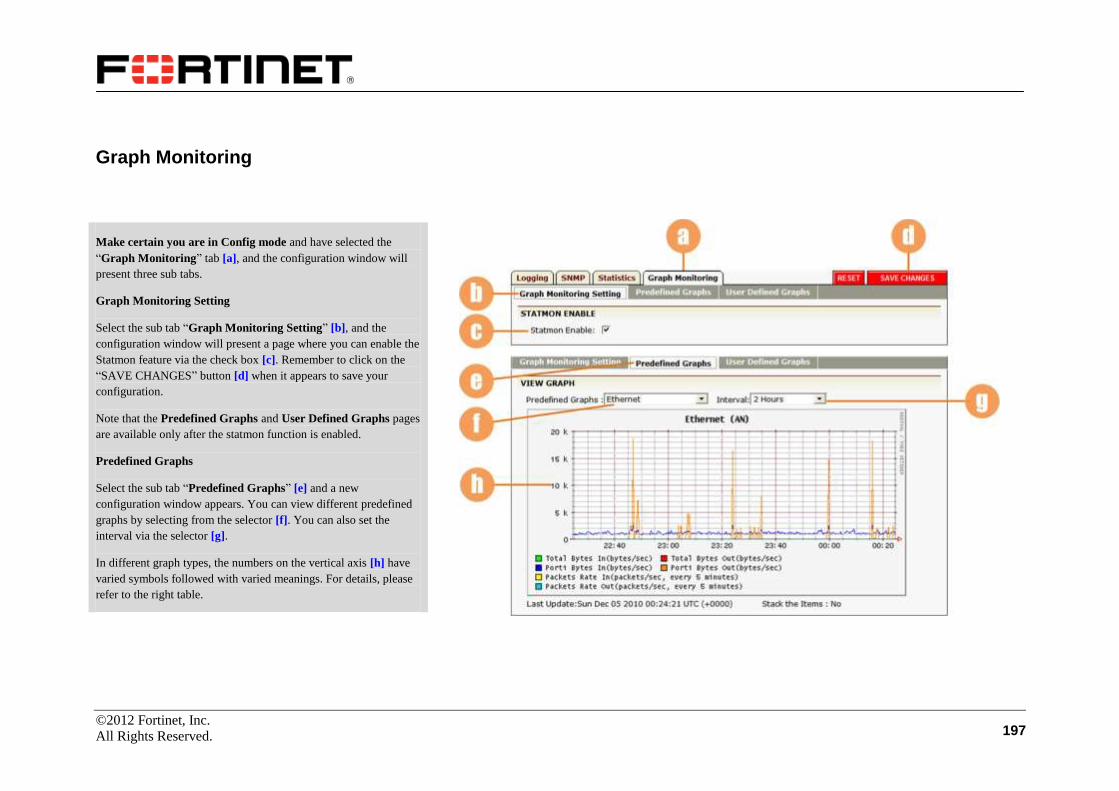
©2012 Fortinet, Inc.
All Rights Reserved. 197
Graph Monitoring
Make certain you are in Config mode and have selected the
“Graph Monitoring” tab [a], and the configuration window will
present three sub tabs.
Graph Monitoring Setting
Select the sub tab “Graph Monitoring Setting” [b], and the
configuration window will present a page where you can enable the
Statmon feature via the check box [c]. Remember to click on the
“SAVE CHANGES” button [d] when it appears to save your
configuration.
Note that the Predefined Graphs and User Defined Graphs pages
are available only after the statmon function is enabled.
Predefined Graphs
Select the sub tab “Predefined Graphs” [e] and a new
configuration window appears. You can view different predefined
graphs by selecting from the selector [f]. You can also set the
interval via the selector [g].
In different graph types, the numbers on the vertical axis [h] have
varied symbols followed with varied meanings. For details, please
refer to the right table.

©2012 Fortinet, Inc.
All Rights Reserved. 198
Graph Monitoring (Continue)
Symbol Meaning Symbol Meaning
a 10e-18 (Ato) k 10e3 (Kilo)
f 10e-15 (Femto) M 10e6 (Mega)
p 10e-12 (Pico) G 10e9 (Giga)
n 10e-9 (Nano) T 10e12 (Terra)
u 10e-6 (Micro) P 10e15 (Peta)
m 10e-3 (Milli) E 10e18 (Exa)
None Base
Predefined Graphs (Continue)
In the “Predefined Graphs” dropdown list, if one item of the graph
types is selected, the number on the vertical axis will have its
corresponding symbol followed. For meanings of these symbols,
please refer to the right table.

©2012 Fortinet, Inc.
All Rights Reserved. 199
Graph Monitoring (Continue)
User Defined Graphs
Select the “User Defined Graphs” sub tab [a], and the
configuration window will present a page allowing you to select to
view preferred graphs.
Input a name for your preferred graph in the text field [b], and click
on the action link “Add” [c]. Then, the added graph name will be
displayed in the list box [d]. You can double-click a name to
further define the graph on a new page.
Select the check box [e] to stack the items, and change the graph
name if needed in the text field [f]. Then, click on the button [g]
when it appears to save changes.
Then, you can define your preferred graph by adding items to the
graph through the parameter fields [h]. After setting them properly,
click on the action link “Add” [i] and the added module will be
displayed in the sort ready table [j].

©2012 Fortinet, Inc.
All Rights Reserved. 200
Graph Monitoring (Continue)
User Defined Graphs (Continue)
Then, click on “User Defined Graphs” [a] again, and you can
view your defined graphs on the page. You can further switch
among the graphs you have defined via the selector [b], or set the
interval as desired via the selector [c].

©2012 Fortinet, Inc.
All Rights Reserved. 201
Troubleshooting
This feature provides simple tools for ping (generate an echo request), packet trace, name server verification and system debugging files exporting.
Tools
Make certain you are in Config mode and have selected
Troubleshooting from the sidebar [a]. The window will present
three tabs. By default, the Tools page is displayed [b].
Ping: To generate a network connectivity echo request directed
towards a specified IP address or “ping”, enter the IP address or
host name and click on the “Ping” button [c]. The ping result will
be displayed in the box [d].
Traceroute: Enter the IP address or host name and click on the
“Traceroute” button [e]. The traceroute result will be displayed in
the box [f]. Here, you are allowed to set the traceroute timeout
value (in seconds, defaults to 5) in the text field [g].
Name server lookup: This feature allows the user to verify the IP
address for the given hostname. Enter the IP address or host name
for the name server and click on the “Lookup” button [h]. The
verification result will be displayed in the box [i].

©2012 Fortinet, Inc.
All Rights Reserved. 202
Tools (Continue)
Build Debug Files: Via this operation, the system will generate four
kinds of system debug files which respectively record the system
activities information by categories:
sys_snap.tar.gz
sys_log.tar.gz
sys_core.tar.gz
app_core.tar.gz
You can manually generate and obtain these files. First, set the
number of the debug files to obtain (0-10, 0 means do not obtain
any file) [a], and click on “Build” [b].
After a while, the system debug files obtained successfully will be
displayed in the sort ready table [c].
Export debug files: You can export the system debug files via the
local file, FTP or SCP method. Select a file to export [d], and
specify the export method via the radio buttons [e]. For the FTP
and SCP method, you need to input the IP address of the FTP or
SCP server and the user name and password to access the server
[f]. Then, click on “Export” [g].
Note: The “sys_debug” system debug file in the list is generated by
successively executing the command “debug enable” and “debug
disable” via CLI. Users can also export the file here.

©2012 Fortinet, Inc.
All Rights Reserved. 203
Debug Monitor
Select the “Debug Monitor” tab [a].
You can enable or disable the debug monitor function via the check
box [b], and then click on the “Set” action link [c] to make your
configuration take effect. By default, the debug monitor function is
enabled.
You can self-define the CLI commands to be executed for monitor
purpose in a file, and then import the file via FTP or SCP method.
To import the file, input user name, password, IP address of the
FTP or SCP server and the file name in the text fields [d], and click
on the “Import” action link [e].
After the file is imported successfully, the CLI commands defined
in the file will be displayed in the area [f]. The system will execute
these commands every 1 minute automatically and further save the
monitor data.
You can also export the monitor data via FTP or SCP method.
Input user name, password, IP address of the FTP or SCP server in
the text fields [g], and click on the “Export” action link [h]. For
SCP method, you further need to input the directory path to save
the monitor data [i].
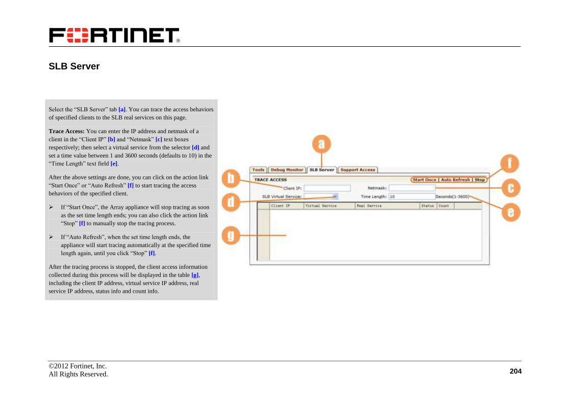
©2012 Fortinet, Inc.
All Rights Reserved. 204
SLB Server
Select the “SLB Server” tab [a]. You can trace the access behaviors
of specified clients to the SLB real services on this page.
Trace Access: You can enter the IP address and netmask of a
client in the “Client IP” [b] and “Netmask” [c] text boxes
respectively; then select a virtual service from the selector [d] and
set a time value between 1 and 3600 seconds (defaults to 10) in the
“Time Length” text field [e].
After the above settings are done, you can click on the action link
“Start Once” or “Auto Refresh” [f] to start tracing the access
behaviors of the specified client.
If “Start Once”, the Array appliance will stop tracing as soon
as the set time length ends; you can also click the action link
“Stop” [f] to manually stop the tracing process.
If “Auto Refresh”, when the set time length ends, the
appliance will start tracing automatically at the specified time
length again, until you click “Stop” [f].
After the tracing process is stopped, the client access information
collected during this process will be displayed in the table [g],
including the client IP address, virtual service IP address, real
service IP address, status info and count info.

©2012 Fortinet, Inc.
All Rights Reserved. 205
Support Access
This function allows Fortinet Customer Satisfaction personnel
access to the FortiBalancer appliance directly. You should first
contact the Customer Satisfaction department at Fortinet
(1-877-99-Array) before you configure this operation. Select the
“Support Access” tab [a], and all configured access points are
displayed in the sort ready table [b].
To add a support entry, you can click on the action link “Add
Support Entry” [c]. On the new configuration page, supply the IP
address and netmask in the text fields [d] and click on the “Save”
action link [e]. Then, the entry will be displayed in the sort ready
table [b].

©2012 Fortinet, Inc.
All Rights Reserved. 206
User Management
User Management
Make certain you are in Config mode and have selected the User
Management feature link from the sidebar [a]. The configuration
window will display all administrators thus far established in the
“Administrators” list [b].
To edit the account information of an administrator, you can
double-click the user name in the list [c], and change the password
and user level in the parameter fields and dropdown list [d] as
desired on the new configuration page. Then, click on the action
link “Save” to save the new account information [e].
Note: The “Username” field does not support special characters
like “,\t:+&#%$^()!@~*?"<>=|\\/\”. “$” is just allowed as the final
character of the user name.
To add an administrator account, click on the action link “Add
Admin” [f], and a new configuration page appears. Set the
parameters properly in the text fields [g], and click on the action
link “Save” [h]. Then, the newly added administrator will be
displayed in the list [b].

©2012 Fortinet, Inc.
All Rights Reserved. 207
QoS Configuration
QoS
Quality of Service (QoS) for networks is an industry-wide set of
standards and mechanisms for ensuring high-quality performance
for critical applications. By using QoS mechanisms, network
administrators can use existing resources efficiently and ensure the
required level of service without reactively expanding or
over-provisioning their networks.
QoS enables network administrators to manage TCP, UDP or
ICMP flows via queuing mechanism and packet filtering policies.
The FortiBalancer appliance has developed a tree-like queue
structure.
Make certain you are in Config mode, and have selected the
feature link QoS from the sidebar [a]. The configuration window
will present two new tabs. The QoS Entries page is displayed by
default [b].
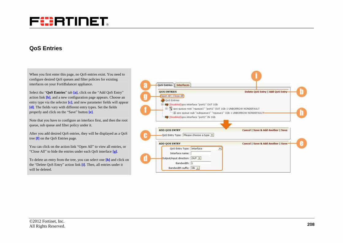
©2012 Fortinet, Inc.
All Rights Reserved. 208
QoS Entries
When you first enter this page, no QoS entries exist. You need to
configure desired QoS queues and filter policies for existing
interfaces on your FortiBalancer appliance.
Select the “QoS Entries” tab [a], click on the “Add QoS Entry”
action link [b], and a new configuration page appears. Choose an
entry type via the selector [c], and new parameter fields will appear
[d]. The fields vary with different entry types. Set the fields
properly and click on the “Save” button [e].
Note that you have to configure an interface first, and then the root
queue, sub queue and filter policy under it.
After you add desired QoS entries, they will be displayed as a QoS
tree [f] on the QoS Entries page.
You can click on the action link “Open All” to view all entries, or
“Close All” to hide the entries under each QoS interface [g].
To delete an entry from the tree, you can select one [h] and click on
the “Delete QoS Entry” action link [i]. Then, all entries under it
will be deleted.

©2012 Fortinet, Inc.
All Rights Reserved. 209
Interfaces
Select the “Interfaces” tab [a] and the page will display basic
information about the interfaces previously configured on the QoS
Entries page in the table [b]. You can enable the QoS policies of an
interface on OUT or IN direction by selecting the desired check
box [c] and clicking on the “SAVE CHANGES” button [d].

©2012 Fortinet, Inc.
All Rights Reserved. 210
Statistics
QoS Interface Statistics
Select the feature link Statistics from the sidebar [a]. To view the
statistics, you only need to enter the Enable mode.
The configuration window will present the QoS Interface Statistic
page [b]. You can view the QoS statistics of existing interfaces on
either in, out, or both directions.
Specify an interface via the selector [c], and further specify a
direction (IN or OUT) of the interface from the selector [d], where
“ANY” means both the IN and OUT directions. Then the desired
interface statistics will be displayed in the table [e]. You can click
on the action link “Refresh” [f] to view the latest statistics.
To clear the statistics, you need to enter the Config mode and click
on the “Clear” action link [g].