12c bus protocol
TRANSCRIPT

I2C BUS PROTOCOL
CHINARI S SAKTI
1NH02EC011
DEPT OF ECE

EVOLUTION OF I2C
developed in the early 1980's by Philips Semiconductors
Its original purpose was to provide an easy way to connect a CPU to peripheral chips in a TV-set.
I2C BUS PROTOCOL
I2C BUS PROTOCOL
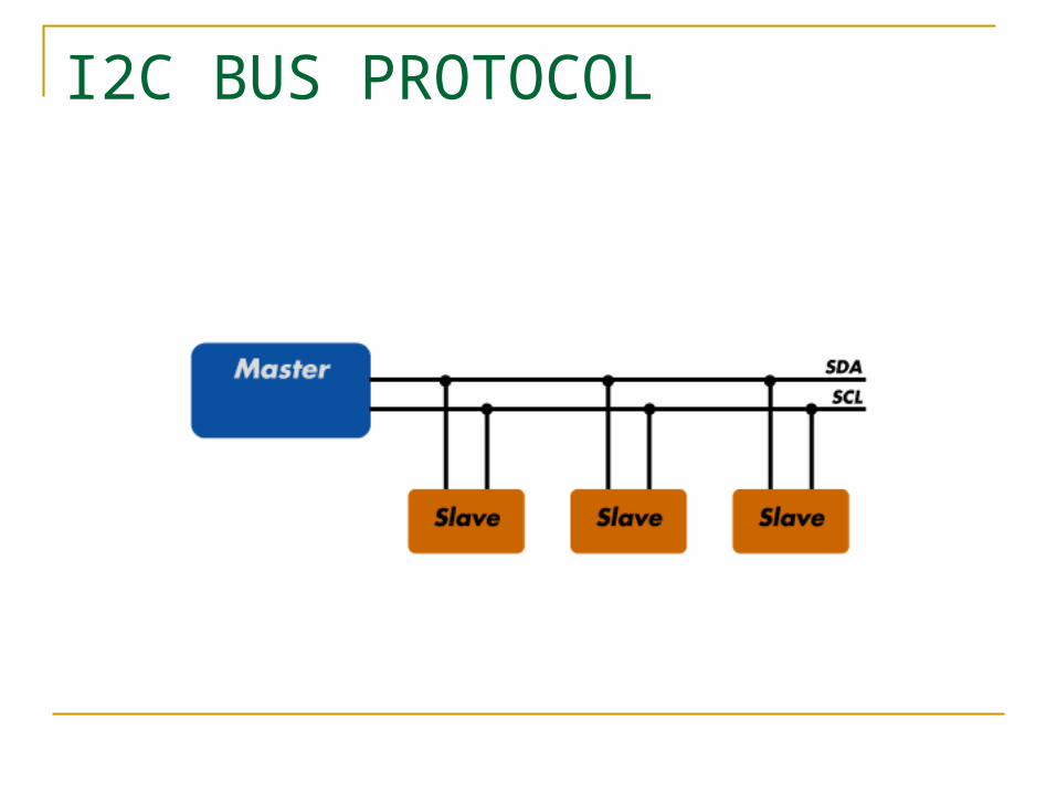
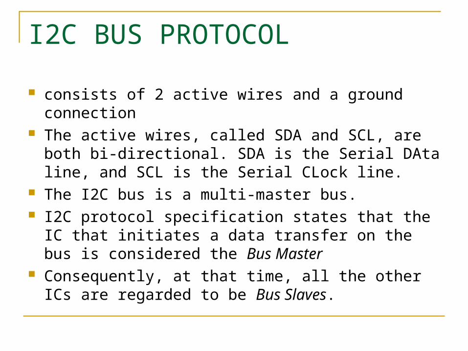
consists of 2 active wires and a ground connection The active wires, called SDA and SCL, are both bi-
directional. SDA is the Serial DAta line, and SCL is the Serial CLock line.
The I2C bus is a multi-master bus. I2C protocol specification states that the IC that
initiates a data transfer on the bus is considered the Bus Master
Consequently, at that time, all the other ICs are regarded to be Bus Slaves.

I2C BUS HARDWARE STRUCTURE

I2C BUS HARDWARE STRUCTURE Physically consist of 2 active wires: sda(data)
and scl(clock). Both are initially bidirectional. These signals use open collector or open
drain outputs (depending on the technology). When bus is idle it is logic HIGH state.

I2C BUS ARBITRATION
The I2C bus was originally developed as a multi-master bus
using only one master on the bus there is no real risk of corrupted data
situation changes with 2 MCU's

I2C BUS ARBITRATION

I2C BUS ARBITRATION
when one of the MCU's missed the START condition and still thinks the bus is idle, this leads to problems.
How can you know if some other device is transmitting on the bus ?
What about the risk of data corruption ?

CLOCK SYNCHRONISATION
All masters generate their own clock on the SCL line
Data is only valid during the HIGH period of the clock
A defined clock for bit-by-bit arbitration performed using the wired-AND connection of
I2C interfaces to the SCL line
I2C BUS EVENTS
the start condition the stop condition transmitting a byte to a slave receiving a byte from slave giving acknowledge to a slave getting acknowledge from a slave no acknowledge
THE START CONDITION
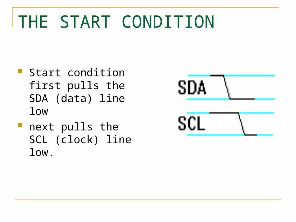
Start condition first pulls the SDA (data) line low
next pulls the SCL (clock) line low.

THE STOP CONDITION
The Bus Master first releases the SCL and then the SDA line.
A Stop condition ALWAYS denotes the END of a transmission
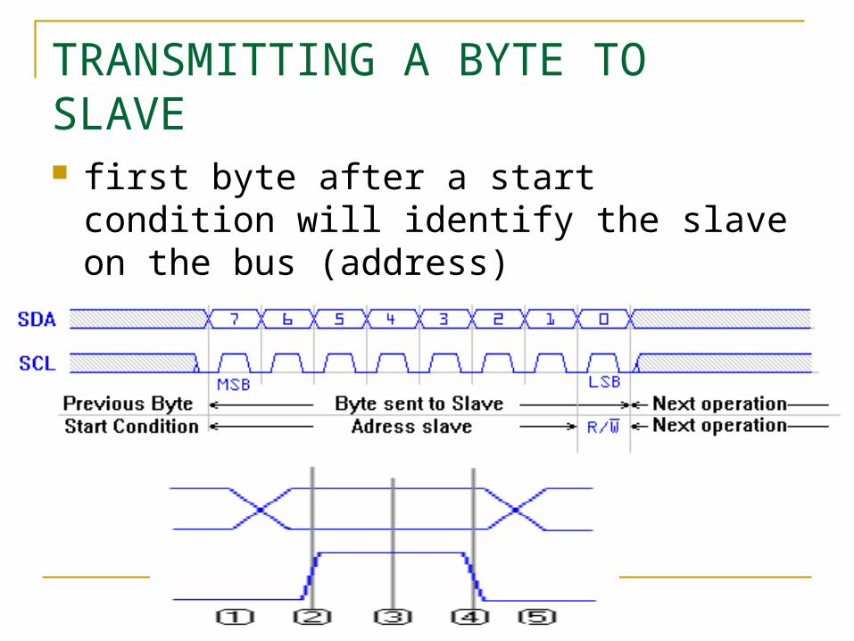
TRANSMITTING A BYTE TO SLAVE first byte after a start condition will identify the
slave on the bus (address)

RECIEVING A BYTE FROM SLAVE a byte can be received from the slave if the
R/W bit in the address was set to READ (set to '1').

GETTING ACKNOWLEDGE FROM SLAVE ACKNOWLEDGED by the slave pulls the SDA line low immediately after
reception of the 8th bit transmitted

GIVING ACKNOWLEDGE TO A SLAVE Upon reception of a byte from a slave, the
master must acknowledge this to the slave device.
NO ACKNOWLEDGE
Not merely a condition but a state If slave doesnot pull the sda line low Happens when slave is not there (in case of
an address) The slave missed a pulse and got out of sync
with the SCL line of the master The bus is "stuck". One of the lines could be
held low permanently.

TRAMSMITTING MODES
Standard mode:
bit rate of 100Kbps. Enhanced I2C:
bit rate of 400Kbps. High speed I2C:
bit rate of 3.2Mbps

ADDRESSING MODE
7 bit addressing (standard) 10 bit addressing (extended)
THEORY OF OPERATION
The Master device issues a start condition. This condition informs all the slave devices to listen on the serial data line for instructions.
The Master device sends the address of the target slave device and a read/write flag.
The Slave device with the matching address responds with an acknowledgement signal.
Communcation proceeds between the Master and the Slave on the data bus. Both the master and slave can receive or transmit data depending on whether the communcation is a read or write. The transmitter sends 8-bits of data to the receiver which replies with a 1-bit acknowledgement.
When the communication is complete, the master issues a stop condition indicating that everything is done.
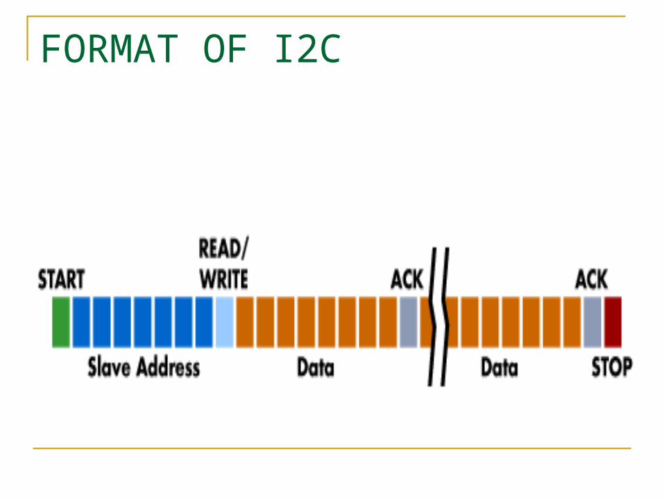
FORMAT OF I2C

FORMAT OF I2C
SCL
SDL
...
MSBstart
...
ack
...

FLOWCHART FOR MASTER

Sending start condition
Start sending serial address of the slave
Receiving ack from slave
Start
Receiving data
Sending ack to slave
Sending data
Receiving ack from slave
Check 7th bit of initial
byte
Sending stop condition
stop
Receiving ack from slave
Sending slave location address serially
‘1’ read‘0’ write

FLOWCHART FOR SLAVE

receiving start condition
Receiving serial address of the slave
sending ack to master
Start
Receiving data from master
Sending ack to master
Sending data to master
Receiving ack from master
Check 7th bit of initial
byte
Detecting stop condition
stop
sending ack to master
receiving slave location address
Checking for address
false
true
‘0’ write‘1’ read

FEATURES
multiple data speeds Built in collision detection, 10-bit Addressing, Mutli-master support, Data broadcast (general call).

BENEFITS
Since only 2 wires Reduces cost Reduces complexity Increases the number of devices on a board

DRAWBACKS
Due to the presence of only two wires, complexity in handling the overhead of
addressing and acknowledgments
COMPANIES ADOPTED I2C
XicorST Microelectronics Infineon TechnologiesIntel Texas Instruments Maxim Atmel Analog Devices and others.
REFERENCES
www.philipssemiconductors.com www.esacademy.com www.totalphase.com www.embedded.com

THANK YOU!
ANY QUESTIONS ?