12/31/05chapter i · web viewthe composition and description of the booklet are made for the...
TRANSCRIPT

CHAPTER I
ATC LABORATORY
1.1.General
1.1.1 Air Traffic control laboratory (subsequently is named LAB) is the practical activities as a part of the subject of Aerodrome Control Procedure (ADC) and/or Approach (APP) and Area Control Procedure (ACC). The objective of the practical training is to provide the students with opportunity to apply their knowledge ( which is obtained from the classical or theoretical training) and to familiarize themselves in simulated operational environment of the Aerodrome Control Tower (TWR), approach Control office (APP) and Area Control Center (ACC).
1.1.2 The purpose of TWR simulation is to permit the student to practice aerodrome control tower activities in order to :a) Familiarize the student with the basic concepts related to this type
of control and the role of TWRb) Expose them to traffic flow in the vicinity of aerodrome.c) Impress on them the need for close coordination, constraints of
TWR and factor / situation affecting IFR departure / arrival andd) Improve coordination practice.
1.1.3 Whereas the purpose of APP / ACC simulation is to permit the student to practice approach office and area control center activities in order to :a) Familiarize the students with the basic concepts related to this type
of control and the role of APP and ACC.b) Expose them to traffic flow within controlled airspace.c) Impress on them the need for close coordination, constraints of
APP/ACC and factor / situation affecting IFR departure / arrival andd) Improve coordination practice
1.2.Requirement
1.2.1. Before going to the relevant laboratory, the students are required to have sufficient knowledge in :
1.2.1.1. For Tower LAB :1) Aerodrome control service / procedure 2) Lay out of aerodrome3) Flight progress strip (strip marking)4) Aircraft type and performance5) Coordination and6) Phraseology
1.2.1.2. For APP / ACC-LAB :1) Approach and area control service / procedures.
Technical and Aviation Safety Academy of MEDAN 2nd Revision, 10, 2007 – Aviation Safety Division1

2) Structure of airspace and ATS route.3) Flight progress strip (strip marking)4) Estimating process and plotting5) Coordination and6) Phraseology.
1.3.Structure
The structure and procedures which are used in the LAB are fictive and designed such a manner that cover all aspect associated with the function of Air Traffic Control. The composition and description of the booklet are made for the purpose of giving the student with a model of local procedure that will hopefully be able to be developed in the future.
--------- 0 ---------
Technical and Aviation Safety Academy of MEDAN 2nd Revision, 10, 2007 – Aviation Safety Division2

CHAPTER II
AIR TRAFFIC CONTROL SERVICE
2.1 Application
Air Traffic Control Service (ATCS) will be provided to all flight within controlled airspace (control zone/control area/terminal control area ) and to all aircraft at controlled aerodrome.
2.2. Division of Air Traffic Control Service
2.2.1. Air Traffic Control service is divided into :
a. Aerodrome Control service : is provided by Aerodrome Control Tower (TWR) for aerodrome traffic, which excludes parts of those flight under jurisdiction of Approach Control Offices (APP)
b. Approach Control service ; is provided by Approach Control Service (APP) for those parts of controlled flights associated with departure and arrival.
c. Area Control Service : is provided by Area Control Center (ACC) for those parts of controlled flight during en-route phase.
2.2.2. Responsibility
2.2.2.1. The responsibility for control of individual flight at any given time shall be vested in a single Air Traffic Control Unit. When circumstances required, control of one or more than one aircraft may be delegated to other AYC Unit provided coordination between the relevant units has been effected.
2.2.3. Air Traffic Control Clearance
2.2.3.1 Scope
2.2.3.1.1. Authorization for an air traffic to proceed for the portion or portions of a flight shall be issued by the respective ATC Unit prior to an aircraft is permitted to operate in any control area.
2.2.3.1.2. Clearance are based on know traffic conditions which affect safety in aircraft operation. Such traffic conditions include not only aircraft in the air and on the maneuvering area but also, Vehicular traffic or other obstruction not permanently installed on the maneuvering area in use.
Technical and Aviation Safety Academy of MEDAN 2nd Revision, 10, 2007 – Aviation Safety Division3

2.2.3.2. Issuance
2.2.3.2.1. The issuance of the ATC clearance by an ATC unit constitutes authority for an aircraft to proceed only in so far know is concerned and base solely on expediting and separating air traffic and do not constitute authority to violate any applicable regulations for promoting safety of flight operation for any other purpose.
2.2.3.2.2. ACC shall issue clearance to APP and/or TWR as soon as on receipt of request by any of the ATS Unit then the relevant ATS Unit shall issue , as appropriate, the ATC clearance as soon as possible, in order to avoid unnecessary delay to aircraft.
2.2.3.2.3. A Control instruction issued subsequent to clearance amends the appropriate item in the clearance. When there is any change to the clearance limit and/or route specified in the original clearance, a complete new clearance shall be issued.
2.2.3.2.4. When an item the initial clearance differs from that contained in the flight plan, a brief statement as to the reason for the change shall be in the clearance when necessary. The pilot shall be required to acknowledge the emended item.
2.2.3.2.5. The clearance shall be made in such a way that the flight will be cleared by most efficient separation and/or route.
2.2.3.3. Content
2.2.3.3.1. ATC clearance shall contain the following items :a. Prefixb. Aircraft identificationc. Clearance limitd. Route of flighte. Level andf. Any necessary instruction or information.
Note : Prefix (ATC CLEARS) will only be used if the clearance is issued through a communication agency.
2.2.3.4. Clearance limit
2.2.3.4.1. Aircraft shall be cleared o the aerodrome of first intended landing, reporting point or common airspace boundary. The clearance limit and route instruction shall be included in the following circumstances a) When the aircraft has not been previously cleared to enter the
control area or
Technical and Aviation Safety Academy of MEDAN 2nd Revision, 10, 2007 – Aviation Safety Division4

b) When instrument approaches are required and the aircraft is instructed to proceed to a radio holding point which is situated at a position other than at the destination aerodrome or
c) When aircraft is being cleared to an intermediate point in accordance with point 2.2.3.5. below, the clearance limit in this case shall be the appropriate radio aid selected for route.
2.2.3.5. Clearance to intermediate point
2.2.3.5.1. An aircraft shall not be cleared into succeeding control area until coordination has been effected or unless otherwise agreed with the appropriate controlling authority.
2.2.3.5.2. When coordination has not been effected the clearance limit shall be an appropriate intermediate point. The UTC Unit concerned shall issue instruction to the aircraft to request further clearance from the appropriate unit before arrival at the clearance limit and to hold at the point if further clearance has not been received unless the pilot choose to proceed at his own discretion.
2.2.3.6. Clearance through a control area / control zone
2.2.3.6.1. When a clearance is required for an aircraft to cross through a control area / control zone, controller shall clear an aircraft via a specified point (s) which will describe the flight path to be followed while the aircraft is in the control area / control zone. Traffic information (including current altimeter setting ) shall be passed.
2.2.3.7. Clearance for local flight
2.2.3.7.1. When a clearance is required for an aircraft to proceed on a local flight in the control area/ control zone, the area in which the flight is to be conducted shall be described. Traffic information shall be issued.
2.2.4. Essential traffic
2.2.4.1 Essential traffic is that controlled flight to which the provision of separation by ATC is applicable, but which, in relation to particular controlled flight, is not separated by standard minima set forth for the system.
2.2.4.2. Essential traffic shall be given to controlled flight concerned whenever they constitute essential traffic to each other such as at the following situation :
a) when through emergency or other cause, aircraft are operating with less than the prescribed separation minima ,or
Technical and Aviation Safety Academy of MEDAN 2nd Revision, 10, 2007 – Aviation Safety Division5

b) when in VMC, separation is not provided between aircraft (descent/climb maintain own separation while in VMC) or
c) when visual approaches are being conducted, aircraft are descending in en-route aerodrome below the control area and it is know that other aircraft are operating below the control area in close proximity to such movement, or
d) when an aircraft has been instructed to operate in accordance with VFR (canceling IFR), or
e) when requested by the pilot- in command of an aircraft
2.2.4.3. Essential traffic information shall include the following items :
a) direction of flightb) type of aircraftc) flight level/altitude andd) ETA/ATA at a position such a reporting point, point of crossing flight
paths and point of passing or overtaking.
2.3. Aerodrome Control Service
2.3.1. Provision of service
2.3.1.1 Aerodrome Control Tower (TWR) shall provide ;
a) Aerodrome Control Serviceb) Flight Information Servicec) Alerting Service.
2.3.2. Responsibility
2.3.2.1. The Tower shall responsible for the safe, orderly flow and expeditious flow of air traffic by :
a) the issuance of instruction and information to aircraft under its control
b) the establishment of separation between arriving, departing, over flying, and locally operating aircraft and
c) the control of vehicular and pedestrian movement, including aircraft movement, on the maneuvering area.
2.3.3 Division of control
2.3.3.1. Aerodrome control may be divided into :
a) air control andb) ground (movement ) control.
Technical and Aviation Safety Academy of MEDAN 2nd Revision, 10, 2007 – Aviation Safety Division6

2.3.3.1.1. Air control shall be responsible for the provision of service to aircraft flying in the vicinity of aerodrome and to aircraft taking off or landing. It shall have absolute authority over all movements on runway and their access point.
2.3.3.1.2. Ground (movement ) control is established for the provision of services to aircraft, pedestrian and vehicles in the apron and maneuvering area other than runway.
2.3.4. Control of surface traffic
2.3.4.1. The movement of aircraft, person or vehicles on the maneuvering area and the movement of aircraft on the apron shall be subject to approval and control from aerodrome control.
2.3.4.2. The Tower has the authority to issue or with hold, on traffic ground permission for pedestrian or vehicular movement on the maneuvering area when permitted, such movement shall be rigidly position.
2.3.4.3. In circumstances where the apron may be out of sight from Tower control responsibility then is limited to providing advice. Instruction shall be issued to aircraft that are in view from Tower position.
2.3.4.4. The following procedures may be adopted to control movement of aircraft
2.3.4.4.1. An aircraft is cleared to taxi. A second aircraft may be given taxi clearance coupled with information on the position and intention of the first aircraft with clear instruction to follow or give way to it.
2.3.4.4.2. An aircraft is cleared to taxi and all further request for aircraft movement are refused until the first aircraft comes into sight of the controller. A second movement is then approved following the same procedure.
2.3.4.4.3. An aircraft is cleared to taxi and asked to report when cleared of the apron or passing an easily identifiable reference point. A second aircraft may be cleared subject to the know progress of the first.
2.3.5. Turbulence in aerodrome surface operation
2.3.5.1. Turbulence caused by engine efflux is different phenomenon to vortex (wake turbulence) resulting from trailing vortices, but it may also cause hazard to aircraft operating behind the larger jets. Therefore, the following shall apply :
Technical and Aviation Safety Academy of MEDAN 2nd Revision, 10, 2007 – Aviation Safety Division7

2.3.5.1.1. Clearance or instruction which imply indicate approval of rolling take-off are not to be issued to aircraft with maximum take-off weight of more than 170.000 kg ( Tupolev 144, Boeing 747, Lockheed 1011, DC 10 Mc Donnel Douglas, Galaxy C5A etc) For this purpose a rolling take off is defined as one which requires as one which requires more than normal power to be used to enter the runway.
2.3.5.1.2. Clearance or instruction which requires aircraft as above listed to use more than normal power for taxiing are not to be issued.
2.3.6 Taxi clearance
2.3.6.1. Taxi clearance shall be issued to control the movement of aircraft taxiing on the maneuvering area. Clear, concise and precise taxi instruction shall be given particularly with wide-bodied aircraft where the pilot’s visibility from the flight deck is limited.
2.3.6.2. The following information, in order listed below, shall be given to aircraft prior to taxiing :a) Aircraft identificationb) Instruction “taxi to” c) Runway numberd) Current surface wind direction and speed including significant
changese) Time checkf) QNH (altimeter setting)g) Information, if any.
2.3.6.3. When it is know that aircraft has received such element (from ATIS, for example ), only runway-in-use shall be passed.
2.3.6.4. A taxi clearance shall consist of the taxi clearance limit which will normally be the holding position for the runway-in-use and details of the routes to be followed. The routes to be followed shall be specified in sufficient time to enable the pilot to take action promptly.
2.3.6.5 After landing, clearance necessary for the control of ground traffic, and taxi instruction to assist the pilot in locating his terminal shall be issued. Any special clearance or information relating to turning-off immediately from the runway after landing, if practicable be given with the landing clearance.
2.3.6.6. Where sectionalized taxiway lighting is provided , it shall be used at night to indicate progressively the route to be followed by an aircraft.
2.3.7. Critical position of aircraft in the taxi circuit
Technical and Aviation Safety Academy of MEDAN 2nd Revision, 10, 2007 – Aviation Safety Division8

2.3.7.1. Tower shall maintain a continuous watch on all visible traffic on the surface of aerodrome and shall control such traffic in accordance with the procedure set forth herein and all applicable traffic rules.
2.3.7.2. The following positions of aircraft in taxi circuit area positions where the aircraft will normally receive clearance/instruction, whether these are given by light signals or radio. The aircraft should be watched closely as they approach these position so that proper clearance/instruction may be issued without delay. Where practicable, all clearance shall be issued without waiting for the aircraft to initiate the call.a) Position 1 : Aircraft initiates call – request for taxi clearance will
normally be made by aircraft. Runway-in-use information and taxi clearance will be given.
b) Position 2 : Aircraft will call for take-off clearance. If there is conflicting traffic, the departing aircraft will be held at this position. Engine of the aircraft will normally be run up here.
c) Position 3 : Take off clearance is issued here, if not practicable at position 2.
d) Position 4 : Clearance to land is issued here as practicablee) Position 5 : Clearance to taxi to the appropriate position on the
aerodrome (hangar line or Parking area) issued here.f) Position 6 : parking information issued here if necessary.
2.3.8. Traffic control in the vicinity of aerodrome
2.3.8.1. Departing aircraft shall :
a) not be held beyond the holing point of the taxiwayb) not be permitted to hold at the end of the runway if another aircraft
has been cleared to landc) not be permitted to line up on the runway if another aircraft has
been cleared to carry out an overshoot.
2.3.8.2. Only one aircraft at any one time shall be permitted to line up on any runway prior to taking–off
Technical and Aviation Safety Academy of MEDAN 2nd Revision, 10, 2007 – Aviation Safety Division9

2.3.8.3. Aircraft is not to be given take–off clearance until :
a) for IFR, the ATC clearance from APP has been passed to and acknowledged by aircraft.
b) APP has authorized its departure (release) and any specific instruction have been passed to aircraft.
2.3.8.4. Take off clearance shall be issued when the aircraft is ready for take-off and at or approaching the runway-in-use, and when traffic subject to the pilot accepting the clearance.
2.3.8.5. A clearance for immediate take-off may be issued to an aircraft before it enters the runway in order to expedite traffic subject to the pilot accepting the clearance.
2.3.8.6. When a light and heavy aircraft both ready for take-off at the same time, the controller should generally clear the light aircraft for take-off first in order to avoid wake turbulence, provided no undue delay would be created for the heavy aircraft. Such clearance should provide for a turn after take-off to ensure expeditious clearing the flight part for the following departing aircraft.
2.3.8.7. If it appears that a take-off clearance may be delayed for more than three minute, the pilot shall be advised of the reason for the delay and the time at which take-off clearance may be expected unless the reason apparent : e.g other aircraft ahead awaiting take-off clearance.
2.3.8.8. If the pilot of an IFR flight specifically request permission to depart and maintain VFR until the IFR clearance is received, take-off clearance in this instance may be issued provided prior approval, with limitation if necessary, has been obtained from the appropriate ATS unit.
2.3.8.9. When a requested clearance has been withheld or deferred by controller, actual clearance shall be given when condition permit, without further request from pilot.
2.3.8.10. Take-off from an intersection resulting in use of less than the full usable length of the runway may be authorized when requested by the pilot or suggested by the controller. When an intersection take-off is suggested by the controller, the pilot shall be informed of the usable length of the runway remaining from the intersection.
2.3.8.11. Before clearance for take-off is given, any significant changes in wind direction and/or speed, the visibility or RVR values, operational status of visual / non visual aids and any significant meteorological conditions in the take-off or climb out area shall be passed.
Technical and Aviation Safety Academy of MEDAN 2nd Revision, 10, 2007 – Aviation Safety Division10

2.3.9 Issuance of ATC clearance
2.3.9.1 Aerodrome Control Tower shall issue ATC clearance as required to meet the objectives of collision prevention and the expedition and maintenance of an orderly flow or air traffic
2.3.9.2. If a pilot request a clearance to manoeuver his aircraft in a manner different from that specified, a new clearance in accordance with the request shall be issued if and when traffic condition permit.
2.3.9.3. When any part of a clearance is issued to aircraft differs from the corresponding part in the approved flight plan, the controller shall request the pilot to read back the appropriate part of the clearance.
2.3.10. Withholding a clearance
2.3.10.1. The person listed below are empowered to prohibit flight and they may instruct/request controller to withhold a clearance :a) Director General of Air Communication (Senior Officer on behalf of
Airport Manager or Above)b) Indonesian Police or Security Agency through Airport Authorityc) Airport Customs through Airport Authorityd) Airport Immigration through Airport Authoritye) Airport Quarantine through Airport Authority
2.3.10.2. To avoid problem which can arise with ATC’s withholding of clearance, the supervisor or his controller shall take precautionary steps to establish the authenticity of person giving instruction or requesting withholding.
2.3.10.3 The following action shall be taken :
2.3.10.3.1. Obtain full particular of the caller which include ;a) Nameb) Government Departmentc) Designation and rank andd) Reasons (if available) for prohibition of flight
2.3.10.3.2. ATC on receipt of the message shall take the particulars of the caller and then return the call to ascertain the identity of the caller. This is necessary to ascertain frivolous call or hoaxes.
2.3.10.3.3. The pilot-In Command shall be instructed to :a) delay start-up if he calls for start-up clearanceb) hold at the holding position if he has commenced taxing.
Technical and Aviation Safety Academy of MEDAN 2nd Revision, 10, 2007 – Aviation Safety Division11

c) Take the first available turn off the runway (subject to traffic condition ) if he has not begun his take-off.
Note : After transmitting the instruction (s) ATC shall advise the pilot-in-command using phraseology “ STANDBY FOR AN URGENT MESSAGE”
2.3.10.3.4. When the authenticity of the authority issuing the detention order is confirmed, controller shall issue, as appropriate, the following instruction using phraseology : “YOUR AIRCRAFT HAS BEEN DETAINED BY…. ( authority issuing detention order). I AM UNABLE TO ISSUE (taxi/take-off) CLEARANCE”
2.3.10.3.5. Record the incident and actions taken on the control log book
2.3.11. Arriving Aircraft
2.3.11.1. An IFR Flight may be cleared to execute visual approach provided that pilot has the aerodrome in sight, can maintain visual reference to terrain and visibility is at least 1 statute mile and :
a) if the reported ceiling is at or above the approved initial approach level for the aircraft so cleared, or
b) if the report at the initial approach level or at any time during instrument approach procedure that the visibility will permit a visual approach and has reasonable assurance that the landing can be accomplished.
2.3.11.2. IFR separation shall be effected between aircraft execute visual approach and other departing or arriving aircraft.
2.3.11.3. When a clearance for visual approach is issued, no further altitude assignment need be made.
2.3.11.4. An arriving aircraft may be required to report when leaving or passing a reporting point, or when starting procedure / base turn in order to provide positive position information required by the controller to expedite departing traffic.
2.3.11.5. For traffic which will join circuit, landing information shall be given in sufficient time to facilitate operational efficiency. When clearance to the circuit is not given on initial contact, the controller shall ensure that efficient aerodrome and traffic information is made available to the pilot to permit expeditious progress of flight.
2.3.11.6. Instruction to enter a traffic circuit shall be given when an arriving aircraft reports at the transfer point or, in the case of a locally operating flight at nominated fix, or when aircraft already under control is issued with a VFR clearance.
Technical and Aviation Safety Academy of MEDAN 2nd Revision, 10, 2007 – Aviation Safety Division12

2.3.11.7. When traffic is permitting, a controller may clear an aircraft directly to base leg or final approach.
2.3.11.8. The content of initial clearance/instruction are as follows :
a) Aircraft identification.b) Runway number.c) Wind (in degrees magnetic and nautical mile per hour)d) Altimeter setting ande) Instruction and / or information.
2.3.11.9. Controller are required to know the distances and directions of prominent landmarks within a 25 mile radius of the aerodrome which might be used as visual reporting point / holding point , if necessary, shall assist aircraft in determining the location of such landmark.
2.3.11.10. When two or more arriving aircraft are expected to join the traffic pattern simultaneously, controller shall determine the landing sequence which will yield the most expeditious movement of the traffic concerned. Each pilot-in-command shall be informed of this number in the landing sequence. Controller shall ensure by observing the aircraft concerned that each pilot-in-command has identified which he ii to follow.
2.3.11.11. Traffic flow may be considerably expedited by approving or requiring entry into the traffic pattern at a point which affords the shortest flight path of the runway to be used (e.g right base or direct final). Before approving or requiring such action, controller shall give due consideration to the pilot’s ability to keep in sight the preceding aircraft in sequence bearing in minda) the limitation in the aircraft flight desk visibility.b) Glare from the sunc) The contrast formed by an aircraft with the background which it
will appear ,ord) Restriction on atmospheric visibility e.g sudden loss of forward
visibility following descent into a layer of haze.
2.3.11.12. Information to be transmitted to aircraft on the approach phase are as follows :
2.3.11.12.1. At the commencement of final approach ;a) significant changes in surface wind.b) latest information on vertical wind shear/ turbulencec) visibility or RVR values, if practicable
2.3.11.12.2. During final approach :a) sudden occurrence of hazard.b) significant change in the current surface wind
Technical and Aviation Safety Academy of MEDAN 2nd Revision, 10, 2007 – Aviation Safety Division13

c) significant change in runway surface condition.d) change in the operational status of visual or non visual aids.
2.3.11.13. When traffic permitting, when wind speed is relatively higher(15 knot or more),aircraft shall be provided with the wind direction and speed when the aircraft is approximately two mile from the beginning of runway. When traffic does not permit provision of this service, the information shall be broadcasted periodically for the benefit of all aircraft on final approach.
2.3.11.14. Aerodrome control shall use the following terms to describe the runway surface conditions whenever water is present on the runway:
a) DAMP : the surface shows change of color due to moisture
b) WET : the surface is soaked but there is no standing water
c) WATER PATCHES : patches of standing water are visible or
d) WATER COVERED : extending standing water is visible
2.3.11.15. Landing clearance should be issued when the aircraft is on final approach, When traffic permit, clearance shall be issued without waiting for a request from the pilot.
2.3.11.16. Landing clearance shall not normally be issued until the controller is satisfied that the aircraft is on approach to the correct runway. When two or more runway are in use, the runway number shall be included in the landing clearance.
2.3.11.17. When an aircraft is on final approach and it appears that the runway may not be cleared for landing. The aircraft shall be advised to “CONTINUE APPROACH POSSIBLE PULL UP” in lieu of being issued a landing clearance . when a pull up is necessary ( before or being a landing clearance has been issued ) the aircraft shall be advised immediately.
2.3.11.18. When an aircraft reports on the aerodrome frequency at the transfer point, controller shall issue a clearance/instruction, amending as necessary clearance issued by APP. And new or amended information relating to the flight to the aerodrome or to the holding point associated with final approach.
2.3.11.19. Clearance to land shall be given as soon as possible after the aircraft is sighted. In conditions of poor visibility preventing the aircraft from being sighted, clearance to land shall not be denied but shall be issued following the aircraft’s final/runway in sight
Technical and Aviation Safety Academy of MEDAN 2nd Revision, 10, 2007 – Aviation Safety Division14

report. The aircraft is to be advised that controller has not got the aircraft in sight.
2.3.11.20. Tower shall make advance arrangements with APP, in anticipation of aircraft diversion or return to the holding stack when weather conditions point towards probability of missed approaches.
2.3.11.21. Tower shall promptly provide ACC and AIS Unit with the information on the conditions of the movement area and the operational status of the navigational facilities to enable such units to advise all aircraft operating agencies accordingly. The information shall be up-dated, changes in conditions reported without delay
2.3.11.22. Conditions of the movement area and the operational status of the navigational aids shall be monitored, and controller shall promptly provide pilots with information on matters of operational significance.
2.3.11.23. A continuous watch shall be maintained for arriving aircraft not equipment with radio communication or suffering from radio failure rendering it incapable of establishing two-way communication.
2.3.11.24. If an aircraft enters a traffic circuit without proper authorization the possibility of an emergency must first be considered. The aircraft shall be permitted to land if its actions indicate that it wishes to do so and , if necessary, other aircraft shall be asked to give way.
2.3.12. Critical position in traffic circuit.
2.3.12.1. Tower shall maintain a continuous watch on all visible traffic in the traffic circuit of aerodrome and shall control such traffic in accordance with the procedure set forth herein and all applicable traffic rules.
2.3.12.2. The following positions of aircraft in traffic circuit where the aircraft will normally receive clearance/instruction, whether these are given by light signal or radio. The aircraft should be watched closely as they approach these position so that proper clearance/instruction may be issued without delay. Where practicable all clearance shall be issued without waiting for the aircraft to initiate the call.
a) Position 1 : Aircraft report on down wind leg when abeam upwind leg end of the runway (pilot may be instructed to report on base leg)
b) Position 2 : Aircraft report on base leg (clearance to land may issued here)
c) Position 3 : Aircraft report on final (clearance to land can be issued here if not practicable in position 2).
d) Position 4 : Aircraft report on long final (between 8 and 4 NM) when aircraft is on straight-in-approach (clearance to land may also be issued here)
Technical and Aviation Safety Academy of MEDAN 2nd Revision, 10, 2007 – Aviation Safety Division15

2.3.13. VFR flight under Aerodrome Control
2.3.13.1. When VFR flight are operating on the maneuvering area or in the traffic pattern, clearance for effecting separation and for effecting an orderly and expeditious flow of traffic shall be initiated by Aerodrome Controllers. Throughout such operations, the responsibility for avoiding collisions rest with pilot-in-command, but aerodrome controller shall issue essential traffic.
2.3.13.2. In order to apply the required separation between a VFR flight and IFR flight the Aerodrome Controller may withhold take-off clearance for VFR flight or may issue appropriate clearance to a VFR flight already in the air when such clearance would not require the pilot-in-command to contravene the VFR criteria.
2.3.14. Special VFR (SVFR) flight under Aerodrome Control.
2.3.14.1. In the authorizing SVFR flight, the duty of Aerodrome Controller shall issue an ATC clearance which shall specify that the flight be conducted clear of cloud and in sight of ground or water and with a flight visibility of at least 1 NM. In case of local flight, the location and duration and methods of recall if the aircraft is not equipped with a functioning radio shall also be specified.
2.3.14.2. In approving a request for specially authorized flight, the Aerodrome Controller must bear in mind that the aircraft is required to comply with the provisions of the appropriate Civil Aviation Safety Regulation (CASR) with regard to minimum operating heights, and a clearance shall not be issued if the existing ceiling might require an aircraft to contravene the regulation governing minimum operating altitudes.
Technical and Aviation Safety Academy of MEDAN 2nd Revision, 10, 2007 – Aviation Safety Division16

CHAPTER III
PADANG BULAN AERODROME CONTROL PROCEDURE
3.1. General
3.1.1 Padang Bulan Aerodrome Control Tower (BULAN TWR), provide the following services to aircraft :
a) aerodrome control serviceb) flight information servicec) alerting service
3.1.2. Control of traffic on maneuvering area come under the control of BULAN TWR whereas the control of traffic in the air may be shared between BULAN TWR and SELAYANG Approach Control Office (SELAYANG APP). Normally departing IFR traffic will be transferred by BULAN TWR to SELAYANG APP immediately after airborne, while arriving IFR traffic will be transferred by SELAYANG APP to BULAN TWR when properly sequenced for an approach lo land.
3.2. Facilities, Services and Procedures
3.2.1. ATC Unit : PADANG BULAN TOWER (BULAN TWR)Frequency : 118.3 MHz
3.2.2. Airspace dimension :
a) Maneuvering area ( Lateral limit 17 Nm/see detailed information on appendix 1)
b) Vertical Limit : - upper limit : 3000 feet - lower limit : ground or water
3.2.3. Navigational aids :a) VOR : “SLY” frequency 113.0 Mhzb) ILS : Runway 30 on frequency 110.1 Mhz c) NDB : “PB” Frequency 375 KHzd) VASIS : Three bars system.
- Runway 12- Runway 30- Runway 17- Runway 35
e) Signal Area : Landing T, Wind shock, Rotating Beacon, Obstacle Light
Technical and Aviation Safety Academy of MEDAN 2nd Revision, 10, 2007 – Aviation Safety Division17

3.2.4. Infra Structure :
a) Runway- Runway 12 with right hand circuit / Normal Circuit (Obstacle
Chart)- Runway 17 with normal circuit - Runway 30 with normal circuit - Runway 35 with right hand circuit / Normal Circuit (Obstacle
Chart)
b) Taxiway - Taxiway Alpha (A)- Taxiway Bravo (B)- Taxiway Charlie (C)- Taxiway Delta (D)- Taxiway Echo (E)
c) Apron : Main apron
d) Aerodrome lighting- Runway light- Taxiway light- Vasis light- Approach light
3.2.5. Pilot shall request and obtained push back clearance, start engine clearance and taxi instruction and report his aircraft stand number.
3.2.6. Taxiing guidance signs are provided at Padang Bulan aerodrome. Aircraft shall follow the sign accordingly, except when otherwise instructed by BULAN TWR.
3.2.7. Taking-off from taxiway intersection with the runway in use or main intersection may be authorized when requested by pilot or suggested by the controller. When an intersection take-off is suggested by the controller, the pilot shall be informed of usable length of runway remaining from the intersection. It is the responsibility of the pilot-in-command to ensure that TORA is suitable for this particular aircraft.
3.3 Handover Procedure
3.3.1. Before assuming responsibility of their position, the duty TWR controller shall acquaint themselves with weather condition expected during their period of watch by studying current weather report for take off and landing (QAM) or other sources. If necessary, consult with the duty MET Observer or Forecaster.
3.3.1.2. Study all current NOTAM and Supplement information.
Technical and Aviation Safety Academy of MEDAN 2nd Revision, 10, 2007 – Aviation Safety Division18

3.3.1.3. Ensure that they are fully acquainted with the aerodrome condition including runway in use and serviceability state of aerodrome light, VASI, ILS and other things.
3.3.1.4. Acquaint themselves with the position of the aircrafts, vehicles and pedestrian currently under control and with the instruction/clearance which have been issued to them.
3.3.1.5. Ensure that a full appreciation of the air traffic situation is received.
3.3.1.6. Ascertain the time or spacing in term of distance between successive landing aircraft.
3.3.1.7. Conduct checks of all TWR control equipment to ascertain their serviceability state and to take the appropriate action, if necessary. The equipment shall include :a) Telephone links with Briefing Office (BO), Flight Information Center
(FIC), APP, ACC, Fire Fighting Brigade (FFB), Operator (OPR), Military Authority (MILI) or other things.
b) All transmitter and receiver, including standby unit.c) Signal lampd) Any new equipment that might bi installed from time to time.
3.3.1.8. Sign the log book against the time of taking over responsibility, which signature shall confirm that the above procedure have been carried out.
3.4. Start up / push back Procedure for Turbine Aircraft
3.4.1. The normal procedure for a pilot to advise BULAN TWR that it is stating in 3-5 minutes and ascertain that aircraft will get delay due to traffic.
3.4.2. When a delay is expected, BULAN TWR shall advise the pilot of the earlier time of departure.
3.4.3. For a wide-bodied or jumbo jet aircraft, BULAN TWR shall issue a push back time instead of clearance to start up.
3.4.4. Due to possibility of conflict in traffic, a clearance expiry time may be issued with the push back time. A clearance shall be considered cancelled if an aircraft is unable to comply with the time so specified.
3.5. Start up / Push back for Jumbo Aircraft
3.5.1. Aircraft fitted with auxiliary power unit (APU), the following procedure shall apply :
Technical and Aviation Safety Academy of MEDAN 2nd Revision, 10, 2007 – Aviation Safety Division19

3.5.1.1. Aircraft shall start up one engine.
3.5.1.2. Push back shall commence shall one engine has stated up, such engine shall be on idle power at push back.
3.5.1.3. Start up of all other engine shall be made after push back and when the aircraft is positioned on the apron taxiway line.
3.5.2. Aircraft not fitted with auxiliary power unit (APU) or auxiliary power unit (APU) is unserviceable, the following procedure shall apply :
3.5.2.1. Aircraft without APU shall be permitted to start all engine up before push back.
3.5.2.2. Request by pilot top start one engine first (due to special circumstance) and then the rest after completion push back, shall be granted.
3.5.2.3. Push back clearance shall only be granted to one aircraft at a time in apron.
3.6 Start up / Push back Procedure for other Aircraft
3.6.1. Under normal condition aircraft shall start up all engine before commencing push back.
3.6.2. Two aircraft may be given permission to push back simultaneously provided that :
3.6.2.1. They are positioned at least three bays apart (No 1 and No 4)
3.6.2.2. They are separated by at least three bays after the completion of push back
3.6.2.3. They are facing the same direction after push back.
3.7. Engine Run Up
3.7.1. Holding Position runway 12, 17, 30, 35 are designated area for full power engine run up come under the jurisdiction of BULAN TWR.
3.7.2. Request such engine run up shall be made to BULAN TWR
3.7.3. There must be two-way communication at all time (maintaining listening watch) between aircraft and BULAN TWR.
3.7.4. Aircraft doing run up may be granted to an aircraft prior taking off, provided such run up are made from take-off position on the runway and provided that it will not affect other traffic.
Technical and Aviation Safety Academy of MEDAN 2nd Revision, 10, 2007 – Aviation Safety Division20

3.8. Determination of Runway In Use (RIU)
3.8.1. The term of runway-in-use is applied to indicate the particular runway or landing direction by TWR as the most suitable at any particular time. The runway- in-use selected will normally be that the closely aligned to the surface wind direction specially when the wind speed is more than 5 knot. At aerodrome with more than runway TWR will normally nominate the longest runway when the headwind speed is less than 5 knot.
3.8.2. In the determination of the runway in use, the following factor shall be considered :a) types of aircraftb) length of runwayc) wind direction and speedd) traffic dispositione) better approachesf) shorter taxiing distanceg) position of the sun or other weather phenomena in relation to runway
and/orh) necessity to avoid flight over populated area or other reason may be
used.
3.8.3. Operational shall be confined to the most suitable runway for the majority of aircraft/traffic. More than one runway direction shall only be used if necessary :a) due to operational characteristic of particular aircraft orb) to avoid necessary delay.
3.8.4. The responsibility for ensuring that sufficient length or run is available and that cross wind component does not exceeds the maximum permissible for an aircraft operation rest solely with the pilot-in-command.
3.8.5. Should the pilot-in-command advise BULAN TWR that the nominated runway is unsuitable because of operational characteristic of its aircraft permission shall be given to him to select a suitable runway.
3.8.6. It is the sole responsibility of Pilot- in-command to conduct operation where the cross wind component exceeds the maximum permissible for his type of aircraft.
3.8.7. If weather in the vicinity of aerodrome is such that there is cumulonimbus activity with the wind blowing down the runway on the departure part of flight, the controller shall inform the pilot when start up clearance is requested for, of the presence of the cloud and wind condition.
Technical and Aviation Safety Academy of MEDAN 2nd Revision, 10, 2007 – Aviation Safety Division21

3.9 Airfield Inspection
3.9.1. An inspection of the aerodrome surface and boundaries shall be made as soon as practicable :
a) after day light begin.b) before night operation begin.c) after heavy raind) when report are made by pilot of abnormal runway surface ore) when reports are received from maintenance personnel that repairs
on runway resurfacing have been completed.
3.10. Closure or Restricted Operation of Aerodrome
3.10.1. In case accident/incident situation :
3.10.1.1. On the occurrence of an accident situation on the apron or maneuvering area or on received of a report of any hazard to the movement of aircraft on these areas, BULAN TWR shall immediately take the following actions :
a) advice SELAYANG APP and SLY ACC.b) warn all aircraft intending to use the aerodrome of nature and
position of the obstruction of hazard.c) inform the chief of ATS Unit or Airport Manager andd) inform the duty of fire station if any fire which is hazardous to
aircraft operation is observed or if there is likelihood of a fire which may endanger aircraft operation is felt.
3.10.1.2. If immediately action is necessary in the light of prevailing circumstance to close the aerodrome due to unsuitable surface condition or fire, BULAN TWR shall temporarily close the aerodrome and notify immediately to :a) All aircraft affected and which are listening out the TWR
frequency.b) SELAYANG APP and SLY ACC andc) Chief of ATC/ATS Units.
3.10.1.3. The decision to close the aerodrome beyond such interim period lies with the Senior Officer after consultation with chief of ATC.
3.10.1.4. AIS shall be advised, if required, to initiate NOTAM action when the decision of the Senior to close the aerodrome for the period of time has been taken.
3.10.1.5. The decision to reopen the aerodrome rests with the Senior Officer after consultation with the Chief of ATC.
Technical and Aviation Safety Academy of MEDAN 2nd Revision, 10, 2007 – Aviation Safety Division22

3.10.1.6 The duty TWR shall notify all concerned once the aerodrome is open to aircraft operation. AIS shall be asked to issued the NOTAM in this respect.
3.10.2. In weather below minima :
3.10.2.1. If weather in the vicinity of aerodrome in accordance with weather report from Meteorological Officer is such that need the closure of aerodrome due to below minima, BULAN TWR controller after consultation with the Senior Officer, shall immediately take the following action :a) inform SELAYANG APP and SLY ACCb) inform operator and other technical service (air navigation
services)c) warn all aircraft operating on/in the vicinity of aerodrome to take
intention andd) consult at any time with the duty of Meteorological Office on the
improvement likely to occur.
3.10.2.2. When the weather likely become better and the aerodrome may be able to be reopened, notify all concerned once the aerodrome is opened to aircraft operation.
3.11. Air Traffic Control Clearance
3.11.1 BULAN TWR shall normally be responsible for the issuance of ATC clearance for all flight operating within SELAYANG CTR irrespective of weather condition. This function shall be assigned to SELAYANG APP under condition when SELAYANG APP is responsible for control of the control zone.
3.11.2. A clearance by BULAN TWR for an aircraft to enter or cross the SELAYANG CTR shall specify :a) ACIDb) Clearance limit(and holding instruction)c) Route to be flownd) Altitude to be maintained ande) Any other instruction or information.
3.12. Aerodrome Weather Observation and Report
3.12.1. It is responsibility of the TWR controller to advise pilot under his control in the prevailing weather changes significantly from the last reported.
3.12.2 Report by pilot of significant weather phenomena experienced during the final approach phase shall also be relayed to all following aircraft concerned.
Technical and Aviation Safety Academy of MEDAN 2nd Revision, 10, 2007 – Aviation Safety Division23

3.13. Special Visual Flight Rules (SVFR)
3.13.1. BULAN TWR may authorize SVFR flight within SLY CTR after approval has been obtained from SELAYANG APP and provided that weather minima are equal to or better than those prescribe for SVFR.
3.13.2. SVFR authorization should normally be extended to only one aircraft in the CTR at one time, but in some circumstance may arise where a controller may be requested to authorize two or more flight simultaneously.
3.13.3. Controller are cautioned that in such circumstances, they must ensure that: a) All operation can be conducted safely.b) Under complete control within CTR andc) Attention should be paid to the development and agreement of
procedures covering the recall of aircraft as and when necessary and for ensuring that SVFR flight will remain clear of flight path or arriving and departing IFR.
3.14. PADANG BULAN Tower Control Procedures
3.14.1 General
3.14.1.1. Full coordination with the respective ATS Unit is required for all the traffic operating in and outside of the airspace of the BULAN TWR.
3.14.1.2. Controller shall take into consideration the effect of wake turbulence when controlling traffic. It is especially important at SELAYANG APP due to the mixture of aircraft type operating simultaneously
3.14.2 Circuit pattern and height
3.14.2.1. Fixed wing aircraft
a) the circuit pattern
RUNWAY CIRCUIT REMARK12 NORMAL WEST OF OVERHEAD17 NORMAL EAST OF OVERHEAD30 NORMAL WEST OF OVERHEAD35 NORMAL EAST OF OVERHEAD
Technical and Aviation Safety Academy of MEDAN 2nd Revision, 10, 2007 – Aviation Safety Division24

b) circuit heightAIRCRAFT TYPE/ MANOEUVRE HEIGHT (MSL)
Light aircraft and piston engine 500 - 800 feetMedium/heavy and turbine/jet engine 1000 -1500 feetOver flying aircraft (via overhead) At or above 2000 feet
3.14.3. Arrival Procedure 3.14.3.1. IFR arrival which are instructed to make straight in approach
( SELAYANG APP), join final approach course in accordance with the standard instrument approach procedure (SIAP) established for BULAN TWR, whereas arrival which is instructed to make circling approach, after reaching MDA for circling minima (as mentioned in instrument approach chart), proceed to overhead station then join down wind (left/right), whichever is used and make further approach to land.
Note : BULAN TOWER need not to repeat straight in approach clearance which has been given by SELAYANG APP, except if there is a change of runway in use for landing due to wind or other reason.
3.14.3.2. VFR arrival (either incoming from point PAPHA or QIBEC) join downwind (left/right) at circuit altitude. In case arrival are instructed to proceed to overhead station, the arriving aircraft shall maintain 2000 feet until overhead then turn (left/right) join the circuit (as applicable for the runway in use).
3.14.3.3. For the purpose of providing separation : orbit, extend circuit etc, can be exercised provided that all turn shall be effected away from overhead.
3.14.3.4. Arrival, due to traffic density, which can not be instructed to join traffic circuit, may be held over point PAPHA / QIBEC visually. Prior coordination shall be effected with SELAYANG APP before instructing aircraft to hold over such area.
3.14.3.5. There is no mandatory direction from which traffic must join the circuit. However, any deviation from the normal must be coordinated with the appropriate ATS Unit. Active traffic whether reported or not, must also be taken into consideration.
3.14.3.6. For pilot who is not familiar with the aerodrome or who is flying into the airfield for the first time, controller shall initially clear the aircraft to
Technical and Aviation Safety Academy of MEDAN 2nd Revision, 10, 2007 – Aviation Safety Division25
overhead for the pilot to positively identify the airfield then issue subsequent clearance.
3.14.4. Departure Procedure
3.14.4.1. Departure IFR shall be cleared in accordance with the ATC clearance obtained from SELAYANG APP or SLY ACC.
3.14.4.2. Determination of runway in use rests on BULAN TWR controller. Before clearing IFR traffic to depart, release time statement shall be obtained from SELAYANG APP.
3.14.4.3. Departure IFR will be transferred from BULAN TWR to SELAYANG APP immediately after the aircraft airborne.
3.14.4.4. BULAN TWR controller shall ensure that departure IFR is separated from other arriving (IFR/VFR) traffic in accordance with the minima specified at the aerodrome.
3.14.4.5. Departure VFR traffic shall be cleared to be on VFR corridor as soon as possible.
3.14.4.6. Departure VFR traffic will be transferred from BULAN TWR to SELAYANG APP at point PAPHA (for west bound traffic) or point QIBEC (for east bound traffic) or at any point/time/level/ a greed by BULAN TWR and SELAYANG APP.
3.14.5. Separation between Departing and Arriving Traffic
3.14.5.1. Since BULAN TWR is visual controller, it is therefore, providing vertical or horizontal separation in unnecessary. For the purpose of providing separation between VFR flight, traffic information shall be applied instead.
3.14.5.2. Traffic information shall be given to VFR flight concerned whenever they constitute traffic to each other.
Note : 1) Between Departing and arriving VFR flight : traffic information shall be given to both aircraft whatever the ETA difference.
2) Between departing VFR flight or arriving VFR flight traffic information shall be given to both aircraft if the ETA difference is 3 minute or less (traffic information may not be given if the ETA difference is more than 3 minutes).
3.15.5.3. Traffic Information shall include :
a) aircraft identification (ACID)b) type of aircraft concernedc) route of flightd) current position
Technical and Aviation Safety Academy of MEDAN 2nd Revision, 10, 2007 – Aviation Safety Division26

e) level andf) ETA significant point(s)
Example : MNA 5431 (call sign) YOUR TRAFFIC IS ONE CASSA AVIOCAR (type aircraft) COMING FROM NIAS POSITION OVER ORAWA MAINTAINING(or LEAVING/PASSING)5000 FEET ESTIMATING PAPHA 0820(time ETA) if there is additional traffic just add the word ADDITIONAL TRAFFIC ONE…..ETC
3.14.6. Radio Failure Procedure
3.14.6.1. Receiver Failure
3.14.6.1.1. If there is assurance that radio receiver failure occurs(TWR can read the message from pilot but there is no acknowledgement of receipt for any instruction) or pilot cannot read any message the following procedure shall apply :
a) TWR, on observing the aircraft approaching traffic circuit, shall confirm the occurrence by asking the acknowledgement of receipt from the aircraft. When positively the aircraft unable to read the TWR instruction, use light signal for instruction transmission.
b) The aircraft shall proceed to the condition as prescribed in the last instruction and report its position every time passes the reporting point, then join the traffic circuit, acknowledge any TWR instruction (TWR instruction will be given by mean of light signal) and land as appropriate. If landing instruction has not been obtained yet, proceed to overhead station, observe the signal on the signal area and other traffic. Then follow the circuit of the preceding aircraft or as indicated by the signal while awaiting/observing signal lamp from TWR.
c) In the absence of green light or on receipt of a red light when on final approach, the pilot is to overshoot making a turn ( right/left, whichever is used ) for joining downwind (right) and continue approach for runway which is applicable, and on receipt of green light make a landing.
3.14.6.2. Transmitter failure
3.14.6.2.1. If there is assurance that radio transmitter failure occurs (TWR can not read any message neither acknowledgement of receipt from the pilot ) or pilot can read any message but there no response for his transmission TWR the following procedure shall apply :
Technical and Aviation Safety Academy of MEDAN 2nd Revision, 10, 2007 – Aviation Safety Division27

a) TWR, on observing the aircraft approaching traffic circuit, shall confirm the occurrence by asking the acknowledgement of receipt from the aircraft, when positively the aircraft is able to read the TWR instruction, use normal radio communication.
b) The aircraft shall proceed to the condition as prescribed in the last instruction and report his position every time passes the reporting point. Then join the traffic circuit, acknowledge any TWR instruction (TWR instruction will be given by mean of light signal) and land as appropriate. If landing instruction has not been obtained yet, proceed to overhead station until TWR recognize the aircraft and acknowledge any message as requested by TWR.
3.14.6.3. Total Radio Failure.
3.14.6.3.1. If there assurance that total radio failure occurs (TWR can not read the message from pilot and there is no acknowledgement of receipt for any instruction) or pilot cannot read any message the following procedure shall apply :
a) TWR on observing the aircraft approaching traffic circuit, shall confirm the occurrence by asking the asking the acknowledgement of receipt from the aircraft. When positively the aircraft unable to read the TWR instruction, use light signal for instruction transmission.
b) The aircraft shall proceed to the condition as prescribed 3in the last instruction and report its position every time passes the reporting point, then join the traffic circuit, acknowledge any TWR instruction (TWR instruction will be given by mean of light signal) and land as appropriate. If landing instruction has not been obtained yet, proceed to overhead station, observe the signal on the signal area and other traffic, then follow the circuit of the preceding aircraft or as indicated by the signal while awaiting/observing signal lamp from TWR.
c) In the absence of a green light or on receipt of a red light when on final approach, the pilot is to overshoot making a turn (right/left, whichever is used) for joining downwind (right) and continue approach for runway which is applicable, and on receipt of a green light make a landing.
3.14.7 Pilot or ATC Action on Change of Runway
3.14.7.1. It is possible that during the control of traffic, wind condition changed abruptly from the opposite direction. When it happens, TWR
Technical and Aviation Safety Academy of MEDAN 2nd Revision, 10, 2007 – Aviation Safety Division28

controller shall revise runway-in-use and issue revised instruction to all aircraft (departure as well as arrival). For aircraft which is on take off position (about to take off) or on final approach shall be advised. The pilot responsible to determine whether will use runway previously nominated or change another runway.
3.14.7.2. The pattern of arriving aircraft who intends to change the runway in use shall pull up and go round then turn (right/left) to join downwind (right) or base(right) leg of the new runway.
3.14.8. Helicopter Procedure
3.14.8.1. Take off and landing area
3.14.8.1.1. There are two places that have been designated as the helicopter take-off and landing area, those are a:
a) Helipad North West take-off/landing area (northwest spot) : 50 meters north of apron
b) Helipad South East take-off/landing area (south spot) : 75 meters south of apron
3.14.8.1.2. It is desirable that helicopter movement on and in the vicinity of BULAN Aerodrome be operated in such a distance that the sufficient separation with the fixed wing movement exist.
3.14.8.1.3. To avoid possible mistaken identity, the normal or appropriate landing spots are displayed.
3.14.8.1.4. Helicopter (upon request) may land on any part of the aerodrome nearest to the lighting and take off area to enable them to keep taxiing down to minimum. In granting the request, TWR controller must ensure that there are sufficient clearance areas and that no hazard will cause to both persons and properly. For landing, the minimum clearance between rotor tips and the nearest building shall not be less than 100 feet.
3.14.8.2. Approach and Departure Pattern
3.14.8.2.1. Helicopter are not to operate above 500 feet above ground level (AGL) within radius 13 NM centered at BULAN Aerodrome unless authorized by ATC.
3.14.8.2.2. Few minute (5-10 minutes) before approaching point PAPHA/QIBEC, helicopter pilot is to advise ATC on appropriate frequency. ATC is to advise the pilot of the landing direction, altimeter setting, surface wind etc.
Technical and Aviation Safety Academy of MEDAN 2nd Revision, 10, 2007 – Aviation Safety Division29

3.14.8.2.3. All approach/turn after take off shall be made in accordance with pattern established for SLY APT. Approach to land direction 12, 17 and take off direction 30 and 35 from/to north spot using North West spot.
Approach to landing direction 30, 35 and take off direction 17 and 12 from/to south spot using South East spot.
Approach to land direction 12, 17 and take off direction 30 and 35 from/to south spot using North West Spot.
All Helicopters that use runway for take off and landing shall using the runway in use.
3.14.8.2.4. After take-off, the helicopter is to be flown not above 500 feet AGL until radius 13 NM from BLN AD.
3.14.8.3. Ground or Air Taxiing
3.14.8.3.1. After landing, the helicopter is required either to ground or air taxi via the existing taxiways into its allotted parking stands ( Helipad South East or Helipad North West) which will be indicated by a ground signaler using orange bats.
3.14.8.3.2. For take off, the helicopter will either ground or air taxi away from its parking stand and move out of the parking area via existing taxiways to an appropriate spot.
3.14.8.3.3. Helicopter which is landing and intends to park its aircraft at another side of apron, shall be cleared to parking area via taxiways specified in taxi clearance from BULAN TWR.
Note : Ground taxiing are less fuel than air taxi (hovering) and minimize turbulence. However, under circumstance, such as rough, soft or uneven terrain, it may become necessary to hover / air taxi for safety consideration.
3.14.8.4. Radio Failure Procedure
3.14.8.4.1. In the event of failure occurs, if on the ground, shall not be cleared to depart.
3.14.8.4.2. If radio failure occurs while in the air, landing and taxiing clearance will be given by means of the appropriate light signal.
Technical and Aviation Safety Academy of MEDAN 2nd Revision, 10, 2007 – Aviation Safety Division30

3.15. Emergency
3.15.1. An aircraft know or believed to be in state of emergency, including being subjected to unlawful interference, shall be given priority over other aircraft.
3.15.1.1. Unlawful Interference
3.15.1.1.1. Whenever there is any indication of occurrence of unlawful interference with an aircraft, should be handled in accordance with the procedures contained in Air Traffic Management
3.15.1.2. Emergency Conditions
3.15.1.2.1. if you are in communication with an aircraft in emergency (issuing distress message) handle the emergency with the following procedure:a) Confirm the accuracy of message, if the message in unclear.b) Give an appropriate landing instruction by giving the most
nearest and suitable runway.c) Make sure that the expected flight path of aircraft experiencing
emergency will be clear of traffic by transmitting traffic information if any ;
d) Coordination with Fire Fighting Brigadee) Transmit traffic information to other normal aircraftf) Other pertinent actions.
Note : 1. If the position of aircraft experiencing emergency is still far enough and has sufficient time for coordination with the FFB, BULAN TWR does not necessary to push crash bell. Normal coordination can be effected.
2. If the position of aircraft experiencing emergency is close to the aerodrome and has not sufficient time for coordination with the FFB, BULAN TWR is necessary to push bell immediately receive distress message.
3.15.1.2.2. When the only one runway in use is available the normal aircraft on and in the vicinity aerodrome shall be held either overhead station or other holding point until the emergency aircraft positively land at aerodrome.
3.15.1.2.3. If more than one runway are available, other normal aircraft may be assigned with runway other than runway to be used by aircraft emergency.
3.15.1.2.4. If the aircraft emergency ultimated block the runway, coordinate with other technical services and broadcast information to other normal aircraft for intention.
Technical and Aviation Safety Academy of MEDAN 2nd Revision, 10, 2007 – Aviation Safety Division31

CHAPTER IV
STRIP MARKING
4.1. GENERAL
4.1.1. Definition
4.1.1.1. The following definitions are terms associated with the flight progress strip operations which should be understood by controller :
a) BAY : a sloping panel of flight progress board unit.b) BAY DIVIDER : an adjustable horizontal divider used to separate
prepared strip holders being held in suspense bay.c) BOX : one sub division of flight progress strips.d) DESIGNATOR : an approved abbreviation used to identify a
reporting point, holding point or other location.e) FLIGHT PROGRESS BOARD (DISPLAY) : a unit comprising
sufficient bays to accommodate the flight progress strip necessary for the provision of respective ATC unit. The board will normally consist of minimum two bays i.e active and suspense bays. Whereas the active may consist of more than one bay dependent upon the number of designated/holding point or route structures.
f) FLIGHT PROGRESS STIP : a paper strip measuring approximately 26 Cm X 2,5 Cm containing essential flight data necessary for control unit respect to one fix. A strips for the fix representing the point of departure or intended landing is know respectively as a departure or arrival strip
g) STRIP HOLDER : a metal / plastic structure which hold the flight progress strip.
h) SUSPENCE BAY : a bay or portion reserved for the accommodation of strip which is not active strip yet.
4.1.2. Objective of the flight progress strip :
4.1.2.1. The primary objective of flight progress strip are :
1. to enable controllers to visualize current as well as projected traffic situation,
2. to serve as an aide memoirs on the action taken by controller,3. to assist the authority in investigation of accident/incident,4. to serve airport management as data for statistic purposes.
4.1.3. Design and color4.1.3.1. Design of flight progress strips are made in such a way based on the
function of the ATC units(ACC as En route Controller is different to
Technical and Aviation Safety Academy of MEDAN 2nd Revision, 10, 2007 – Aviation Safety Division32

APP/TWR which deals with departing / arriving traffic). Detailed explanation of the flight progress strip boxes is on page 34.
4.1.3.2. Color codes are assigned to flight progress strip to make them distinguishable for control purposes. Three colors are designated for control flight operation namely blue/green, yellow/buff and white. The following flight progress strips are use in the respective ATC Unit in Indonesia :
a) light blue/green : for departure/outbound flight.b) yellow/buff : for arrival/inbound flight.c) white : for local flight.d) plain reserve side of white : for posting flight information of an
urgent matter/nature such as NOTAM,SIGMET etc.
4.1.4. Procedure
4.1.4.1. In the interest of overall efficiency and to avoid misinterpretation, the following flight progress strip principles shall be strictly followed :a) symbol and abbreviation used shall confirm to those listed in ICAO
Document, AIP Indonesia and airways Operation Instruction (AOI)b) entries on air traffic and ATC clearance shall be legible hand
printed (un erasable pencil or ballpoint pen is preferable)c) correction or revision to data posted shall be made by drawing a
single horizontal line through/cross the incorrect data and writing correct data adjacent there to (in the same column / box)
d) do not draw a horizontal line though/cross an altitude being changed until the aircraft has reported leaving altitude.
e) do not erase or overwrite any item.f) insert a check mark(√) against any data to indicate that it has been
passed to either pilot or other ATS Units.
4.1.5. Posting of flight progress strip
4.1.5.1. Arrange flight progress strips under the appropriate designators in the following manners :a) sequence in chronological order of arrival over particular fix (time
sequencing) or in ascending/descending order of assigned altitude over holding fix (level sequencing )
b) time sequencing under the same fix designator with the earliest time at the bottom.
4.1.5.2. Remove the strip marking from the flight progress board when no longer required for control purposes (to avoid incorrect instrument approach clearance issuance, arrival strip of APP will normally be withheld until visual contact information has been obtained from TWR).
Technical and Aviation Safety Academy of MEDAN 2nd Revision, 10, 2007 – Aviation Safety Division33

4.1.5.3. Used flight progress strips shall be filed and in no instance shall such strips be destroyed / thrown away.
4.2. DATA ENTRY
4.2.1. APP and TWR flight progress strip
4.2.1.1. Arrival
4.2.1.1.1. In most cases, the APP flight progress strip is equal to the TWR flight progress strip. The only difference is that TWR as visual controller does not need for insertion of data concerning instrument approach clearance. TWR shall then enter landing time only instead. Whereas the APP as instrument controller need to insert data related to the instrument approach.
4.2.1.1.2. Flight progress strip box function.
A
B
C
D1
D2
D3
E
F
G H J KS
LM
N
P
QR
Legend :
BOX TOWER APPROACH1 2 3A ETA destination aerodrome ETA holding fix/IAFB Time first contact Time first contactC Level of aircraft at transfer time Level of aircraft at transfer timeD Level of aircraft on rep . point Level restrictionE Type, speed and WTC Type, speed and WTCF Aircraft identification/call sign Aircraft identification/call signG Runway in use for landing Runway in use for landingH Blank Time of IAC is given1 2 3J Blank Time of IAP is commencedK Landing time Landing timeL Point of departure Point of departureM Blank ETA holding (feeder) pointN Blank ATA holding (feeder) point P Blank Time leaving holding (feeder)
pointQ Blank ATA inst. App . fix (IAF)R Missed approach time Missed approach timeS Any other pertinent information
such as : ETA’s, conflicting traffic, Any other pertinent information such as : EAT’s , ETA’s reporting
Technical and Aviation Safety Academy of MEDAN 2nd Revision, 10, 2007 – Aviation Safety Division34

communication failure, emergency etc.
point, communication failure, emergency etc.
4.2.2.1. Departure
4.2.2.1.1. In most cases, the APP flight progress strip is equal to the TWR flight progress strip. The only difference is that TWR as visual controller is dealing with push back, start engine and taxi, where as APP is not. For the purpose of conducting the function of instrument controller some boxes are modified which conform to the need of APP.
4.2.2.1.2. Flight progress strip box function
A
B
C
D3
D2
D1
E
F
G H J KN
L MM MM MM
Legend :
BOX TOWER APPROACH1 2 3A ETD ETD B Blank/usable for setting course Time first contactC Intended cruising level Intended cruising levelD Level restriction Level restrictionE Type, speed and WTC Type, speed and WTCF Aircraft identification Aircraft identification1 2 3G Runway in use for take-off Runway in use for take offH Time of start engine Time ATC clearence is given to
TWRJ Time of commencing taxi Release time, if anyK Airborne time Airborne timeL Aerodrome destination Aerodrome destinationM ATC clearance ATC clearanceN Any other pertinent information
such as : ETA reporting points, transfer time to APP
Any other pertinent information such as : ETA reporting points transfer time to ACC etc.
4.2.3.1. Local flight
Technical and Aviation Safety Academy of MEDAN 2nd Revision, 10, 2007 – Aviation Safety Division35

4.2.3.1.1. In most cases, the APP flight progress strip is equal to the TWR flight progress strip. The only difference is that TWR as visual controller is dealing with push back, start engine and taxi, where as APP is not. For the purpose of conducting the function of instrument controller some boxes are modified which conform to the need of APP.
4.2.3.1.2. Flight progress strip box function
A
B
C
DE
F
G H J KQ
L M N P
BOX TOWER APPROACH1 2 3A ETD ETDB Duration of flight Duration of flightC Number of fuel / endurance Number of fuel / enduranceD Intended maneuvering area Intended maneuvering areaE Type, speed and WTC Type, speed and WTCF Aircraft identification Aircraft identificationG Runway in use for take-off Runway in use for take offH Time of start engine Time ATC clearence is given to
TWRJ Time of commencing taxi Release time, if any1 2 3K Airborne time Airborne timeL Runway in use for landing Runway in use for landingM Blank Time of IAC is givenN Blank Time of IAP is commencedP Landing time Landing timeQ Any other pertinent information
such as : ETA reporting points, name pilot in command, etc.
Any other pertinent information such as : ETA reporting points, name pilot in command, etc.
Technical and Aviation Safety Academy of MEDAN 2nd Revision, 10, 2007 – Aviation Safety Division36

CHAPTER V
PHRASEOLOGY
5.1.General
5.1.1. The communication procedure shall be in accordance with Volume II of Annex 10 – Aeronautical Telecommunication and Air Traffic Management- RAC/501/12-. Pilot and ATC personnel shall be thoroughly familiar with the radiotelephony procedures contained therein.
Note : Attention to the students who are acting as pilot that all ATC instruction or clearance shall be read back and ended by acknowledgement of receipt by saying his/her call sign)
5.1.2. Words in parentheses indicated that specific information, such as a level, a place or a time, etc. must be inserted to complete the phrase, or alternatively that optional phrases may be used. Words in square parentheses indicate optional additional words or information that may be necessary in specific instances.
5.1.3. The following are some example of phraseology in various situation which are used by TWR, APP and ACC.
5.2.Aerodrome Control Tower (TWR)
5.2.1. Outbound flight
5.2.1.1. Fixed wing aircraft
5.2.1.1.1. Situation : Aircraft on parking (apron) requests push back Phraseology : A – BULAN TWR MNA 521ON STAND NUMBER- 3
REQUEST PUSH BACK CLEARANCET – MNA 521 PUSH BACK APPROVED {EXPECT} RUNWAY (number)} {EXPECT PUSH BACK AT … (time)} FACE [ WEST/EAST]
5.2.1.1.2. Situation : Aircraft requests start engine Phraseology : A – BULAN TWR MNA 521 {POSITION} REQUEST
START UP {ENGINE} CLEARANCE { BOUND FOR (destination)} T – MNA 521 START UP APPROVED TEMPERATURE (degrees Celsius/centigrade) {EXPECT RUNWAY (number)} {or STANDBY START UP or EXPECT START UP AT (time)}
Technical and Aviation Safety Academy of MEDAN 2nd Revision, 10, 2007 – Aviation Safety Division37
5.2.1.1.3. Situation : Aircraft request taxi from one point to another at aerodrome
Phraseology : A – BULAN TWR PK AGN POSITION STAND NUMBER 1 REQUEST TAXI {CLEARANCE} TO COMPASS SWINGING AREA (or any other location).T – PK AGN TAXI TO COMPASS SWINGING AREA VIA TAXIWAY ALPHA ,ENTERING RUNWAY 30 VIA TAXIWAY BRAVO REPORT…..etc.
5. 2.1.1.4. Situation : Aircraft request taxi for departurePhraseology : A – BULAN TWR MNA 521 {POSITION} REQUEST
TAXI {CLEARANCE} {BOUND FOR (destination)} {VFR/IFR}T – MNA 521 TAXI TO HOLDING POSITION RUNWAY (number) VIA (route of taxiway) WIND (direction and speed) QNH (in whole millibar ) TIME (in minute) HOLD SHORT OF ….etc.
5. 2.1.1.5. Situation : IFR departure is taxiing, hold on short for examplePhraseology : T – MNA 521 CROSS {or ENTER} RUNWAY
(number) ATC CLEARANCE AVAILABLEA – CROSSING RUNWAY (number) GO AHEAD ATC CLEARANCE.T – MNA 521 CLEARED TO (clearance limit) VIA (ATS routes) F 310 AFTER TAKE-OFF TURN LEFT TRACK 090 DEGREES MAINTAIN 3000 FEET
NOTE : No ATC Clearance for VFR Flight
5.2.1.1.6. Situation : Aircraft is ready for take offPhraseology : T – MNA 521 READY [FOR TAKE OFF or FOR
DEPARTURE]A – MNA 521 HOLD POSITION (if any reason) or MNA 521 LINE UP AND WAIT (if any reason) or (if any traffic) MNA 521 TRAFFIC ONE PIPER NAVAJO COMING FROM……
Note : For IFR departure, before issuing take off clearance TWR shall obtained approval (release time) from APP to ensure that the departing aircraft will not conflict with the traffic still under the control of APP.
5.2.1.1.7. Situation : Aircraft is just airborne Phraseology : (IFR) T – MNA 521 AIRBORNE 15 CONTACT [SLY]
APPROACH [ON 119.7][MHZ](VFR)T– MNA 521 AIRBORNE 15 REPORT [PASSING/OVER POINT …..
Technical and Aviation Safety Academy of MEDAN 2nd Revision, 10, 2007 – Aviation Safety Division38

(VFR) A – AIRBORNE 15 WE ARE CLIMBING TO 6000 FEET ESTIMATING [POINT] ….: 20 …[NDB] : 25 MNA 521
5.2.1.1.8. Situation : Departing aircraft (VFR) passing point PAPHA
Phraseology : A - MNA 521 OVER {or PASSING} POINT ALPHA PASSING 1500 FEETT - MNA 521 CONTACK SLY APP {ON 119,7}
5.2.1.1.9. Situation : After contact APP SLY, aircraft report intend to return to base (BULAN MAPT) due to engine failure or other reason.
Phraseology : A - MAYDAY (3 times) BULAN TWR {THIS IS} MNA 521(3 times) DUE TO ENGINE FAILURE WE ARE RETURNING TO PADANG BULAN ESTIMATING BULAN 0710T - MNA 521 ROGER MAYDAY, WIND CALM MAKE STRAIGHT-IN APPROACH RWY 12 REPORT LONG FINAL.
Note : 1. Consideration should be taken that for aircraft having emergency situation should be assigned with the nearest and the most suitable runway in use except for the reason of the amount of cross wind or tail wind component or other reason so that the aircraft is unable to use the assigned runway in use.
2. If the aircraft return to base due to other than distress situation but experiencing technical reason (trouble)TWR can ask whether the aircraft after landing need any assistance or not using the following phraseology : MNA 521 {CONFIRM} DO YOU NEED ANY ASSISTANCE ON ARRIVAL ?
5.2.1.2 Rotary wing (helicopter)
5.2.1.2.1. Situation : A helicopter on apron intend to depart to Gunung Sitoli
Phraseology : H - BULAN TOWER PK HBA POSITION ON APRON REQUEST TAXI CLEARANCE {BOUND FOR} GUNUNG SITOLI.T- PK HBA TAKE OFF DIRECTION 16 WIND (direction and speed), QNH (in whole millibar), TIME ( in minute), TAXI VIA TAXIWAY ALPHA REPORT …. Etc
Note : Subsequent reports are similar to the fixed aircraft.5.2.2. Inbound flight
5.2.2.1. Fixed wing aircraft
Technical and Aviation Safety Academy of MEDAN 2nd Revision, 10, 2007 – Aviation Safety Division39

5.2.2.1.1. Situation : IFR aircraft leaving instrument approach fix (SLY VOR DME / ON NDB ILS)
Phraseology : A – PADANG BULAN TOWER MNA 521 LEAVING {or PASSING} SLY {VOR} {HEADING} INBOUND {AERODROME IN SIGHT or VISUAL CONTACT}
T – MNA 521 REPORT LONG FINAL …etc.
Note : 1. If the arriving IFR does not report aerodrome in sight or visual contact, TWR shall instruct the aircraft to report visual contact or aerodrome in sight first.
2. Approach clearance has been given by APP so TWR need not give landing instruction anymore. Just say REPORT LONG FINAL, except when due to wind or other reason the aircraft will be assigned to another runway, TWR should give additional instruction such as MNA 521 DUE TO WIND CHANGE TO 300/20 CIRLING FOR RWY 30 REPORT RIGHT DOWN WIND RWY 30
5.2.2.1.2. Situation : Arriving IFR has been cleared for instrument approach by APP but wind condition is such that impossible to use the runway specified for straight in approach, the aircraft shall be cleared to make circling approach.
Phraseology : A - PADANG BULAN TOWER MNA 521 LEAVING {or PASSING} SLY {VOR} { or PB NDB}{ HEADING} INBOUND {AERODROME IN SIGHT or VISUAL CONTACT}T - MNA 512 DUE TO WIND CHANGE TO 300/20 CIRCLING FOR RWY 30 REPORT VISUAL CONTACTA - MNA 521 VISUAL CONTACTT - REPORT RIGHT BASE LEG ….etc
5.2.2.1.3. Situation : Arriving IFR unable to establish visual contactPhraseology : A – MNA 521 UNABLE TO ESTABLISH VISUAL
CONTACT {NEGATIVE VISUAL CONTACT} MAKING MISSED APPROACH { WE ARE OVER SHOOTING}
T– MNA 521 STANBY { FOR FURTHER INSTRUCTION}TWR request/inform APP for further instruction and after obtaining an instruction
T – MNA 521 TURN RIGHT AND CLIMB TO 3000 FEET PROCEED TO SLY VOR {or CLIMB
Technical and Aviation Safety Academy of MEDAN 2nd Revision, 10, 2007 – Aviation Safety Division40

STRAIGHT AHEAD TO 2500 FEET PROCEED TO SLY VOR CONTACT SLY APP ON 119,7
5.2.2.1.4. Situation : Arriving IFR, after getting landing clearance from TWR, aircraft is unable to continue its approach to land due to technical reason.
Phraseology : A – MNA 521 DUE TO TECHNICAL REASON WE ARE PULLING UP AND GO AROUND {OVERSHOOTING} DUE TO TECHNICAL REASONT – MNA 521 JOIN DOWN WIND (runway) REPORT DOWN WIND….etc.
Note : Aircraft which is making a missed approach due to technical reason (other than WX reason) such as ; the aircraft is not aligned (is not precisely with runway center line), altitude is too high or too low steep or other reason un necessary to be cleared to original instrument approach fix (IAF). Since the aircraft can maintain visually (or visible to the controller) and there is reasonable assurance that circling can be accomplished, the aircraft may be cleared to join downwind, direction to base leg etc.
5.2.2.1.5. Situation : Arriving VFR is just transferred by APP over RAMPAPhraseology : A – BULAN TWR MNA 521 COMING FROM
KISARAN [POSITION} LEAVING 3000 FEET ESTIMATING QIBEC 20 REQUEST LANDING INSTRUCTION
T – MNA 521 JOIN(down wind/right down wind) [or DIRECT (base leg) or MAKE STRAIGHT IN APPROACH} RWY (number) WIND(direction and speed) QNH (whole millibar) REPORT……. Etc
5.2.2.1.6. Situation : Arriving VFR/IFR are approaching aerodrome, expected runway in use is 12 but wind condition is changed in such direction or the runway in use is blocked by any obstruction (disabled aircraft for example) that need change of runway in use to runway 16
Phraseology : T - MNA 521 DUE TO WIND CHANGE TO 170/16 {or RWY 12 IS BLOCKED BY ONE CESSNA}, RUNWAY IN USE NOW 16 JOIN DOWN WIND REPORT…ect.
5.2.2.1.7. Situation : Arriving VFR approaching overhead station and there have been one or more aircraft (s) on the traffic circuit so that they need sequence properly.
Technical and Aviation Safety Academy of MEDAN 2nd Revision, 10, 2007 – Aviation Safety Division41

Phraseology : T – MNA 521 OBSERVE ONE DAKOTA ON DOWN WIND {or SKYVAN ELEVEN O’CLOCK} TURN RIGHT YOU ARE NUMBER TWO TO LAND , REPORT…etc.orT – MNA 521 YOU ARE NUMBER TWO TO LAND FOLLOW ONE DAKOTA POSITION APPROCHING BASE LEG RUNWAY (number), REPORT…ect.
5.2.2.1.8. Situation : Arriving aircraft experiencing communication failure
5.2.2.1.8.1. Situation : Transmitter failure indicated by the absence of any message or report from the pilot in command. To ensure that aircraft is still able to read any message use the following phraseology.
Phraseology : T – MNA 521 ( BULAN TWR) IF YOU READ ME ACKNOWLEDGE BY ROCKING YOUR WING{or FLASHING YOUR LANDING / NAVIGATIONAL LIGHT TWICE}
Note : If the pilot in command does maneuvers or action as requested it means that the receiver is normal, then the subsequent message be transmitted by means of the appropriate radio communication. Acknowledgement of receipt from aircraft in accordance with TWR’s request.
5.2.2.1.8.2. Situation : Receiver failure indicated by the absence of pilot’s response to TWR’s instruction (acknowledgement of receipt) but message or report from the pilot is unable to read any message use the following phraseology.
Phraseology : T - MNA 521 {BULAN TWR} IF YOU READ ME ACKNOWLEDGE BY ROCKING YOUR WING { or FLASHING YOUR LANDING / NAVIGATIONAL LIGHT TWICE}
Note : if the pilot in command did not do maneuver or action as requested it means that the receiver is failed or unserviceable, than the subsequent message be transmitted by means of light signal. The acknowledgement of receipt from aircraft by means of the appropriate radio communication.
5.2.2.1.8.3. Situation : Total communication failure indicated by the absence of any message or report from the pilot in command. To ensure that aircraft is still able to read any message use the following phraseology.
Technical and Aviation Safety Academy of MEDAN 2nd Revision, 10, 2007 – Aviation Safety Division42
Phraseology : T – MNA 521 {BULAN TWR} IF YOU READ ME ACKNOWLEDGE BY ROCKING YOUR WING { or FLASHING YOUR LANDING / NAVIGATIONAL LIGHT TWICE}
Note : If the pilot in command did not do maneuver or action as requested it means that the receiver is failed or unserviceable, then the subsequent message be transmitted by means of light signal.
5.2.2.1.9. Situation : Arriving aircraft experiencing emergency. Phraseology : A - MAYDAY (3 times) BULAN TWR {THIS IS} MNA
521 (3 times ) POSITION APPROACHING {POINT} QIBEC ENGINE {NUMBER 1/2/3/FAILURE[REQUEST DIRECT BASE LEG RUNWAY ONE TWO }T - MNA 521 ROGER MAYDAY, WIND CALM DIRECT BASE LEG RWY 12 REPORT BASE LEG.
Note : 1. In case the aircraft having emergency situation did not give any reason, TWR may request additional information such as the runway intended to be used for landing, number of persons on board, fuel remaining and other necessary information.
2. Consideration should be taken that for aircraft having emergency situation should be assigned with the nearest and the most suitable runway in use except for the reason of amount of cross wind or tail wind component or other reason so that the aircraft is unable to use the assigned runway in use, another runway assignment may be done.
5.2.2.2. Rotary wing (helicopter)
5.2.2.2.1. Situation : Arriving helicopterPhraseology : A – BULAN TOWER PK HBA COMING FROM
BELAWAN POSITION APPROCHING POINT PAPHA MAINTAINING 1000 FEET REQUEST LANDING DIRECTION.T – PK HBA LANDING DIRECTION 12 WIND 130/10 QNH 1009 REPORT OVER POINT PAPHA.
Note : After report point PAPHA / QIBEC , helicopter is requested to report aerodrome in sight then report final (long final) before landing clearance is given.
5.2.3. Over flying or un expected traffic
5.2.3.1. Situation : Over flying aircraft from Rampa to BinjaPhraseology : A – BULAN TWR MNA 521 {OVER FLYING} FROM
RAMPA TO BINJA APPROACHING A BEAM
Technical and Aviation Safety Academy of MEDAN 2nd Revision, 10, 2007 – Aviation Safety Division43

OSCAR NOVEMBER NDB MAITAINING 2000 FEET ESTIMATING {POINT} QIBEC 20 OVERHEAD STATION 25 {POINT} PAPHA 30 AND BINJA 37T – MNA 521 QNH PADANG BULAN 1009 REPORT ….etc
5.2.3.2 Situation : Unexpected arriving aircraft intends to land at SLY APT
Phraseology : A – BULAN TWR THIS IS DIR 5431, OVERT – DIR 5431 {THIS IS} BULAN TOWER GO AHEADA – DIR 5431 COMING FROM CEMIN LEAVING 2000 FEET ESTIMATING QIBEC 15 PADANG BULAN 20 REQUEST LANDING INSTRUCTIONT – DIR 5431 DIRECT BASE LEG RUNWAY 16 {or JOIN DOWN WIND RWY 34 VIA OVERHEAD} WIND (direction and speed), QNH 1010{ TRAFFIC IS ONE NOMAD COMING FROM BINJA ESTIMATING PAPHA 19 MAINTAINING 2500 FEET} REPORT…..etc.
Note : If there is no information concerning the incoming traffic have been obtained, TWR need to request the information such as the type of aircraft and speed for the provision of traffic information purposes.
Technical and Aviation Safety Academy of MEDAN 2nd Revision, 10, 2007 – Aviation Safety Division44
Attachment 1
TWR/APP/ACC/RDR SIMULATION EVALUATION SHEETName : Date : Ex. No : Post: TWR/APP/ACC/RDR*)
No Evaluation factors/Expected performance
Max Score Description of error(s)
A SEPARATION1. Separation is maintained/ensured2. Selection of separation3. Application of separation4. Degree of precision ( including calculation)5. Traffic information6. Efficiency
30
B CONTROL TECHNIQUE1. Analysis and problem solving2. Planning abilities3. Determining priority / sequence4. Traffic flow / efficiency5. Effective working speed6. Visual scanning7. Aircraft identity is maintained8. Field observation
20
C COMM/CLR/INST/INFO1. Using standard /prescribed phraseology2.Message format accuracy/clarity of
expression3. Timeliness of action/reaction to change4. Realistic instruction5. Microphone technique6. Phonetic alphabet/ voice quality
15
D FLIGHT DATA1. Completeness/correctness of FPS2. Neatness and legibility of FPS3. Correct use of abbreviation/ symbol4. Sequence handling of FPS
5
E COORDINATION1. Clarity of expression2. Promptness / priorities3. Adherence to letter of agreement4. Adherence to the directives
10
F ABNORMAL SITUATION1. Anticipation/reaction2. Judgment
10
G WORK HABIT1. Deportment/attitude2. Initiative3. Attention to detail4. Appearance
10
Total Score = 100 – ……(Error) = Student’s signature Instructor’s signature
Note : 1. Total score : 100 2. Each(one) collision/separation less than minimum = 10
3. *) encircle which one is appropriate
Technical and Aviation Safety Academy of MEDAN 2nd Revision, 10, 2007 – Aviation Safety Division45

Attachment 2
PADANG BULAN VFR CORIDOR
Technical and Aviation Safety Academy of Medan 2nd Revision,10, 2007 – Aviation Safety Division46
To WMKK, WSSS, WSSL, WIDD, WIBT, WIDK, WIDS, WIDN,WIDB
BRAVO
To WIML, WIBB, WIBD, WIBS, WIPL, WIAT, WIIT, WICB, WIII, WIPA, WIPR,
BINJA
ELAWA
CEMIN
ORAWA
STAGI
PAPHA
QIBEC
MNM SEC ALT2700-3590
4000-25 NM
MNM SEC ALT0000-0890
1500-25 NM
MNM SEC ALT0900-1790
7500-25 NM
MNM SEC ALT1800-2690
7500-25 NM
To WMKP, WMKI
To WIMN, WIMS, WIMB, WIMG, WIPT, WIME, WITG
To WITA, WITB, WITC, WITL, WITM, WITN, WITT, WITS
SLY VOR
PB NDB
STABA
ALPHA
DOLOG
PM NDB
NADEM

Attachment 3
VFR Corridor within Selayang Control Zone
IDENTIFICATION
SIGNIFICANT POINT
MAG TRACK
DIST (NM)
UPPER LIMIT LOWER LIMIT
MINIMUM FLIGHT ALTITUDE
WIDTH ATS UNIT RESPONSIBLE
1 2 3 4 5 6 7 8VICTOR STABA SLY APPONE 140 09 119.7 MHz(V-1) 320
BINJA120 10300
PAPHA BLN TWR090 15 118.3 MHz270 6000 FT
QIBEC 3000 FT 5 NM090 10 GND / 270 WATER
CEMIN080 12 SLY APP260 119.7 MHz
BRAVO
VICTOR ALPHA SLY APPTWO 204 12 6000 FT 119.7 MHz(V-2) 024
ELAWA 3000 FT 5 NM180 GND /360 15 WATER BLN TWR
PAPHA 118.3 MHzTWO 200 14 6000 FT(V-2) 020
STAGI GND / 3000 FT 5 NM199 WATER SLY APP019 13 119.7 MHz
DOLOG
Technical and Aviation Safety Academy of Medan 2nd Revision,10, 2007 – Aviation Safety Division47

IDENTIFICATION
SIGNIFICANT POINT
MAG TRACK
DIST (NM)
UPPER LIMIT LOWER LIMIT
MINIMUM FLIGHT ALTITUDE
WIDTH ATS UNIT RESPONSIBLE
1 2 3 4 5 6 7 8VICTOR QIBECTHREE 120 10 BLN TWR(V-3) 300 6000 FT 118.3 MHz
ORAWA GND/ 3000 FT 5 NM123 WATER303 09 SLY APP
PM NDB 119.7 MHzVICTOR STAGITWO A 342 16 BLN TWR(V-2A) 162 6000 FT 118.3 MHz
BINJA GND/ 3000 FT 5 NM027 WATER207 15 SLY APP
ELAWA 119.7 MHzVICTOR STAGIFOUR 085 40 BLN TWR(V-4) 265 6000 FT 118.3 MHz
PM NDB GND/ 3000 FT 5 NM025 WATER205 11 SLY APP
BRAVO 119.7 MHzVICTOR QIBECONE A 022 11 BLN TWR(V-1-A) 202 6000 FT 118.3 MHz
NADEM GND/ 3000 FT 5 NMVICTOR ALPHAFIVE 303 18 SLY APP(V-5) 123 6000 FT 119.7 MHz
NADEM GND/ 3000 FT 5 NM301 WATER121 18 SLY APP
BRAVO 119.7 MHz
Technical and Aviation Safety Academy of Medan 2nd Revision,10, 2007 – Aviation Safety Division48

Attachment 4
IFR And VFR Chart within Selayang Control Zone
SCALE 1 CM = 3.3 NMAttachment 5
Technical and Aviation Safety Academy of Medan 2nd Revision,10, 2007 – Aviation Safety Division49
VOR/DMESLY-113.0
NDB/ILSPB -375 Khz/110.1 M

MNM SEC ALT270 0 -359 0
4000-25 NM
NDB/ILSPB-375Khz/110.1 M
MEDAN TOWN
MEDANTOWN
MNM SEC ALT000 0 -089 0
1500-25 NM
300 0
120 0
MNM SEC ALT1800-2690
7500-25 NM
MNM SEC ALT0900-1790
7500-25 NM
INSTRUMENT ELEV : 30 FT MEDAN/BulanAPPROACH CHART Height Related to MSL INDONESIA NDB/ILS RWY 30
MISSED APPROACH PROCEDURE TRANSITON LEVEL : FL 180 climb to 2500’ to proceed to SLY VOR/DME or TRANSITION ALT : 16,000 FTAs instructed by ATC PB 2500 3000
1200 3000 3000
MAPt
THR 33 FT 0 1 2 3 4 5 6 7 8 9 10
OCA (H) Dist. Fm. SLY VOR TO MAPt 9 NMCat of acft A B C D SPEED 100 125 150 165Straigth -in 475 (417) 485 (427) MIN : SEC 5:34 4:27 3:55 3:23
Circling 690 (607) 710 (627) R/D 485 585 810 820
Attachment 6
Technical and Aviation Safety Academy of Medan 2nd Revision,10, 2007 – Aviation Safety Division50
APP : 119,7TWR : 118,3

INSTRUMENT ELEV : 30 FT MEDAN/BulanAPPROACH CHART Height Related to MSL INDONESIA VOR/DME RWY 17
Technical and Aviation Safety Academy of Medan 2nd Revision,10, 2007 – Aviation Safety Division51
APP : 119,7TWR : 118,3
MALAKA SEA
VOR/DMESLY-113,0
170
170350
BINJAI
BRASTAGI
BELAWAN
MEDANTOWN
MNM SEC ALT2700-3590
4000-25 NM
MNM SEC ALT0000-0890
1500-25 NM
MNM SEC ALT0900-1790
7500-25 NM
MNM SEC ALT1800-2690
7500-25 NM

MISSED APPROACH PROCEDURE TRANSITON LEVEL : FL 180Turn right and climb to 3000’ to proceed to SLY VOR / DME or TRANSITION ALT : 16,000 FTAs instructed by ATC 1700 SLY 3000’ 3500
1700 1600 MAPt
THR 30 FT 10 9 8 7 6 5 4 3 2 1 0
OCA (H) Dist. Fm. SLY VOR TO MAPt 9 NMCat of acft A B C D SPEED 100 125 150 165Straigth -in 475 (417) 485 (427) MIN : SEC 5:34 4:27 3:55 3:23
Circling 690 (607) 710 (627) R/D 485 585 810 820
Attachment 7
Technical and Aviation Safety Academy of Medan 2nd Revision,10, 2007 – Aviation Safety Division52
H
H

Attachment 8
``
Technical and Aviation Safety Academy of SELAYANG First Revision, 09, 2006 – Aviation Safety Division
53

Attachment 9
`
Technical and Aviation Safety Academy of SELAYANG First Revision, 09, 2006 – Aviation Safety Division
54
TERMINAL

Attachment 10
Technical and Aviation Safety Academy of Medan 2nd Revision, 10, 2007 – Aviation Safety Division55
SOUTH EAST SPOT
H1
H2
to 30 to 35
ldg 12 ldg 17
to 17
ldg 35
to 12
ldg 30
NORTHWEST SPOT
TOWER
N
S

Attachment 11
AERODROME CONTROL LABORATORYPADANG BULAN TOWER
PROBLEM TRAFFIC STATUS EXPECTED PERFORMANCE
01 DEP VFR Taxi & Take-off (Piston Engine)
02 DEP VFR/IFR Start Up, Taxi & Take off ( Piston + Turbo Engine)
03 ARR VFR Landing instruction, Sequence Arrangement
04 DEP/ARR VFR Departure & Arrival Procedure + Traffic Info
05 DEP/ARR VFR Idem + Ground Vehicle + Helicopter Operation
EX I DEP/ARR VFR/IFR ALL ITEM WHICH HAS BEEN EXERCISED
06 DEP/ARR VFR Idem + Local Flight
07 DEP/ARR VFR Idem + Un Expected Traffic + Over flying
08 DEP/ARR VFR Idem + Communication failure
09 DEP/ARR VFR/IFR Idem + Dep/IFR + Multi Rwys Operation
10 DEP/ARR VFR/IFR Idem + Arr/IFR ( Instrument Approach)
EX II DEP/ARR VFR/IFR ALL ITEM WHICH HAS BEEN EXERCISED
11 DEP/ARR VFR Missed approach + Special VFR Operation
12 DEP/ARR VFR/IFR General Procedure
13 DEP/ARR VFR/IFR Idem + Change of Runway
14 DEP/ARR VFR/IFR Idem + Urgency Situation
15 DEP/ARR VFR/IFR Idem + Emergency Situation
EX III DEP/ARR VFR/IFR ALL ITEM WHICH HAS BEEN EXECISED
Technical and Aviation Safety Academy of Medan 2nd Revision, 10, 2007 – Aviation Safety Division56

Attachment 12
AIRCRAFT APPROACH CATEGORY
Note :
1. Aircraft performance has direct effect on the airspace and visibility needed to perform the various maneuvers associated with the conduct of instrument approach procedure.
2. The most significant factor is the speed.
3. Approach speed categories are established based on 1-3 times the stall speed in the landing configuration at maximum certificated landing mass.
AIRCRAFT CATEGORY
AIRCRAFT SPEED (KT) EXAMPLE
A <91 BE35, HS14, CS12, DC3, BN3, ETCB 91-<121 BE90, BE10, FK27, IL18, CN35, DA10, DA20,
VC8, L382, ND 16, HS74, LR28, LR29,ETCC 121-<141 FK28, DC9, B727, BA11, FK10, VC10,
LR54/55/56, B767, EA30, B707, TU14, B757, C5A, B737, HS21, HS25, L101, DC10, AN22, IL76, ETC
D 141-<166 LR35/36, B747, DC8, TU34, TU54, IL62, CV99, CONC, ETC
E 166-<211 TU44, SR71, MILI JET, ETC
Technical and Aviation Safety Academy of Medan 2nd Revision, 10, 2007 – Aviation Safety Division57

Attachment 13
LOCATION INDICATOR.ENCODE DECODE
NAME OF AIRPORT/CITIES
LOCATION
INDICATOR
LOCATION
INDICATOR
NAME OF AIRPORT/CITIES
ADI SUCIPTO / JOGYAKARTA WARJ WAAA HASANUDIN / UJUNG PANDANG
AEK GODANG / P. SIDEMPUAN WIME WADD NGURAH RAI / BALI
AEK LOBA/KISARAN WIML WARJ ADI SUCIPTO / JOGYAKARTA
AHMAD YANI / SEMARANG WARS WARR JUANDA / SURABAYABINAKA/GUNUNG SITOLI WIMB WARS AHMAD YANI / SEMARANG
BUDIARTO / CURUG WIAB WIBB SULTAN SYARIEF/PEKANBARU
C NYAK DIEN/MEULABOH WITC WIBD PINANG / DUMAI
DABO/SINGKEP WIDS WIBS SUNGAI PAKNING/BENGKALIS
DEPARTI PARBO / KERINCI WIPH WIBT SEIBATI/T. BALAIDEPATI AMIR/ P. PINANG WIDK WICB BUDIARTO / CURUG
FATMAWATI/BENGKULU WIPL WICC HUSEIN SASTRA N / BANDUNG
HALIM P KUSUMA/JAKARTA WIHH WIDD HANG NADIM/BATAMHANANDJOEDDIN/ TJ PANDAN WIDB WIDK DEPATI AMIR/ P. PINANG
HANG NADIM/BATAM WIDD WIDN KIJANG/T.PINANGHASANUDIN / UJUNG PANDANG WAAA WIDS DABO/SINGKEP
HUSEIN SASTRA N / BANDUNG WIAA WIHH HALIM P KUSUMA/JAKARTA
JAPURA / RENGAT WIPR WIII SOEKARNO HATTA/JAKARTA
JUANDA / SURABAYA WARR WIAT RADIN INTEN / LAMPUNGKIJANG/T.PINANG WIDN WIMB BINAKA/GUNUNG SITOLI
LASIKIN/SINABANG WITG WIME AEK GODANG / P. SIDEMPUAN
LHOK SUKON WITL WIML AEK LOBA/KISARANMAIMUN SALEH/ B ACEH WITB WIMN SILANGIT / TARUTUNGMALIKUS SALEH/LHOKSEUMAWE WITM WIMP SIBISA / PRAPAT
MINANG/PADANG WIPT WIMS PINANG SORI/SIBOLGA
NGURAH RAI / BALI WADD WIDB HANANDJOEDDIN/ TJ PANDAN
PADANG BULAN/SELAYANG WISY WIOO SUPADIO / PONTIANAK
Technical and Aviation Safety Academy of Medan 2nd Revision, 10, 2007 – Aviation Safety Division58
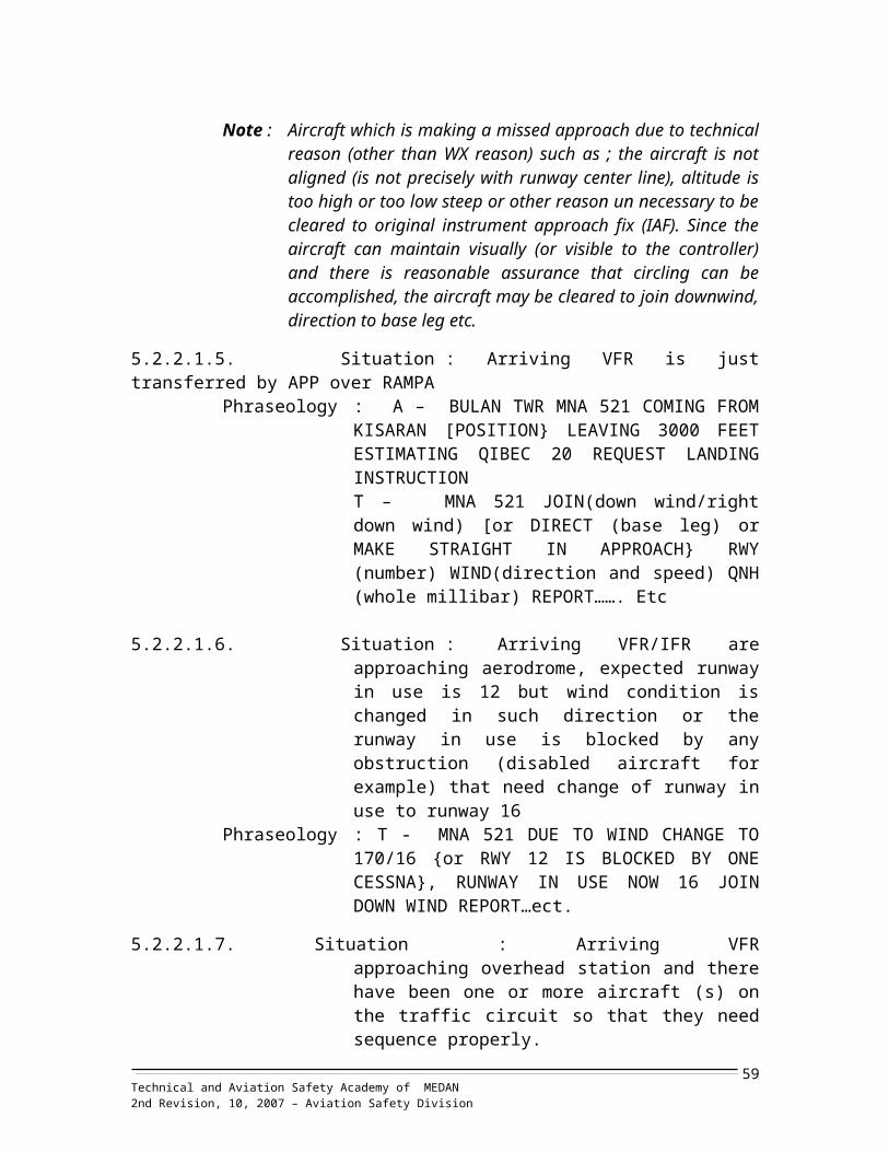
PINANG KAMPAI / DUMAI WIBD WIPA SULTAN THAHA/JAMBIPINANG SORI/SIBOLGA WIMS WIPE TANJUNG ENIM /BANGKORADIN INTEN / LAMPUNG WIAT WIPH DEPARTI PARBO / KERINCIS ISKANDAR MUDA/ B ACEH WITT WIPL FATMAWATI/BENGKULUSABANG WITN WIPP SMB II / PALEMBANGSEIBATI/T. BALAI WIBT WIPR JAPURA / RENGATSIBISA / PRAPAT WIMP WIPT MINANG/PADANGSILANGIT / TARUTUNG WIMN WISY PADANG BULAN/SELAYANGSMB II / PALEMBANG WIPP WITA T CUT ALI/ TAPAK TUANSOEKARNO HATTA/JAKARTA WIII WITB MAIMUN SALEH/ B ACEHSULTAN SYARIEF/PEKANBARU WIBB WITC C NYAK DIEN/MEULABOH
SULTAN THAHA/JAMBI WIPA WITG LASIKIN/SINABANGSUNGAI PAKNING/BENGKALIS WIBS WITL LHOK SUKON
SUPADIO / PONTIANAK WIOO WITM MALIKUS SALEH/LHOKSEUMAWE
T CUT ALI/ TAPAK TUAN WITA WITN SABANGTANJUNG ENIM /BANGKO WIPE WITT S ISKANDAR MUDA/ B ACEH
Technical and Aviation Safety Academy of Medan 2nd Revision, 10, 2007 – Aviation Safety Division59
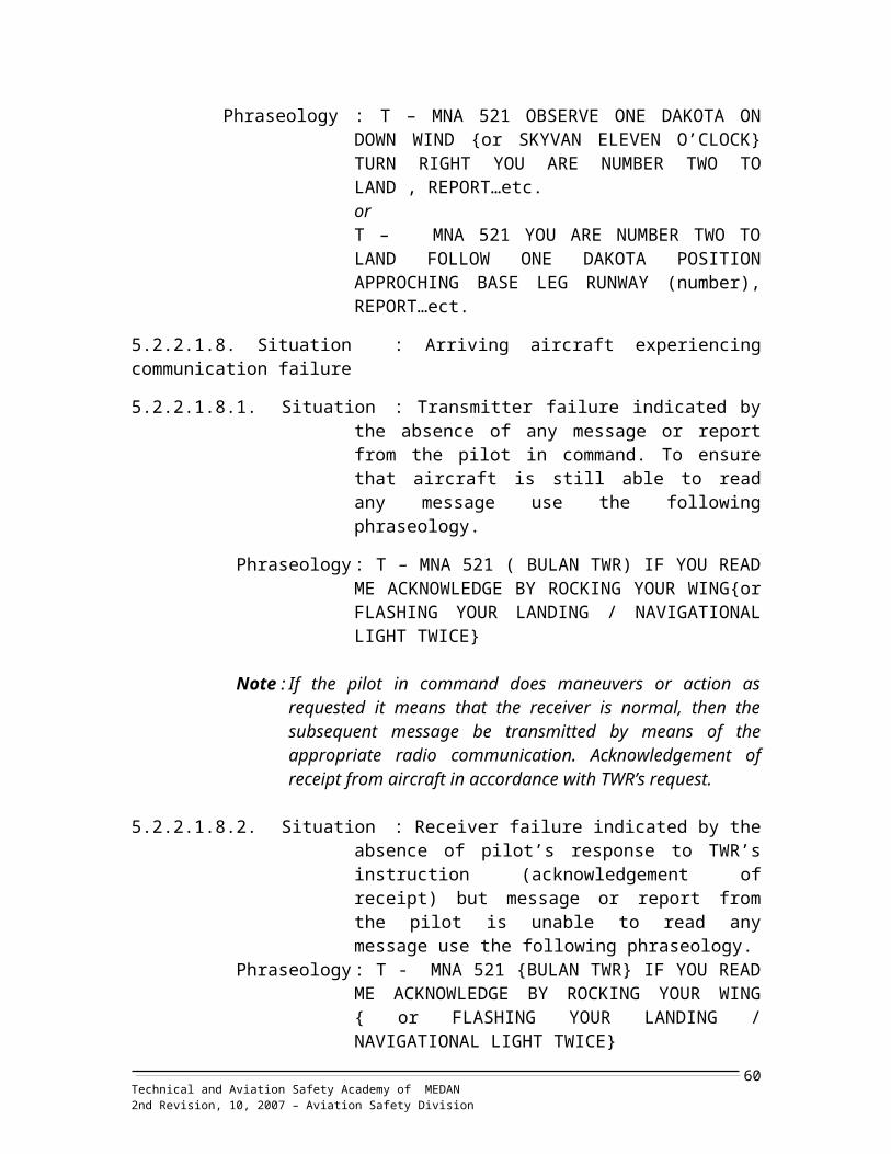
Attachment 14
AIRCRAFT NATIONALITY AND REGISTRATION MARK
ENCODE DECODE
STATES NATIONALITY MARK
NATIONALITY MARK STATES
AUSTRALIA VH AP PAKISTAN
BANGLADESH S2 CCCP RUSSIA
BELGIUM OO D GERMANY
BURMA XX,XZ DQ FIJI
FIJI DQ F FRANCE
FRANCE F G UNITED KINGDOM
GERMANY D HB SWTZERLAND
INDIA VT HL KOREA
INDONESIA PK HS THAILAND
ITALY I I ITALY
JAPAN JA JA JAPAN
MALAYSIA 9M N UNITED STATES
NETHERLAND PH OO BELGIUM
NEW ZEALAND ZK, ZL, ZM PH NETHERLAND
PAKISTAN AP PK INDONESIA
PAPUA NEW GUINEA PZ PZ PAPUA NEW GUINEA
PHILIPINES RP RP PHILIPINES
KOREA HL S2 BANGLADESH
SINGAPORE 9V VH AUSTRALIA
SRILANKA 4R VT INDIA
SWTZERLAND HB XX,XZ BURMA
THAILAND HS ZK, ZL, ZM NEW ZEALAND
RUSSIA CCCP 4R SRILANKA
UNITED KINGDOM G 9M MALAYSIA
UNITED STATES N 9V SINGAPORE
Technical and Aviation Safety Academy of Medan 2nd Revision, 10, 2007 – Aviation Safety Division60

Attachment 15
RESPONSIBILITY OF FEEDER AND PILOT
I. FEEDER POSITION1. Function
The Function of feeder is a supplier unit represents the relevant technical units which supply information to ATC unit currently in operations, it is therefore it acts as one or more ATS unit(s) or other technical unit(s).
2. ResponsibilityTower SimulatorAt Tower Simulator, Feeder will act as :1) Briefing Office which supplies ETD, NOTAM, etc,;2) APP which coordinates for departure /arrival of IFR traffic;3) Fire Fighting Unit which coordinates in case of emergency exercise;4) Meteorological office which supplies weather report for take-off and
landing (QAM);5) Adjacent ATC/ATS unit(s)6) Other relevant units.
II. PILOT POSITION1. The responsibility of Pilot Position is to record all data required in
accordance with the progress of flight at all time reference to flight level, time, position, clearance/instruction, etc on the pilot strip.
2. Guidance for data insertion on the pilot strips are as follow :Note : Data which will be inserted on pilot strips based on the data on the scenario sheet.
PROBLEM DEPARTURE AIRCRAFT
PILOT : 1CALL SIGN : PK ZAQ TYPE : C212/P/L DEST : WIMSETD : 05.20 SPD/LVL: NO150/060 POSITION: BAY 7
TIME COMMUNICATION/ACTIVITIES REMARKS05.16+3 – 4 ……
+ 3+ 1
REQUEST TAXI CLEARANCEREADY FOR DEPARTURECLIMBING TO 6000 FEETESTIMATING PAPHA (+3) STAGI (+5)OVER PAPHA PASSING 2000 FEETCLIMBING PASSING 3000 FEET
RWY : 12 (+3) 17 (+4) 30 (+4) 35 (+3)
Technical and Aviation Safety Academy of Medan 2nd Revision, 10, 2007 – Aviation Safety Division61

PROBLEM ARRIVAL AIRCRAFTPILOT : 1CALL SIGN : PK ATK TYPE : C212/P/L DEP : WIDNETA : 03.10 SPD/LVL : 160/VFR POSN : CEMIN
TIME COMMUNICATION/ ACTIVITIES REMARKS0303
+ 4
+ 2
…..
APPROACHING CEMIN LEAVING 3000 FEET
ESTIMATING QIBEC 07 PADANG BULAN 10
REQUEST LANDING INSTRUCTION
OVER QIBEC (MAINTAINING ) 2000 FEET
(SHOW YOUR AIRCRAFT – FOLLOW ATC
INSTRUCTION )
(TAXI FOLLOW TAXI INSTRUCTION)
+2:D/W RWY 17- 35
+3:D/W RWY 12- 30
PROBLEM EMERGENCY AIRCRAFT PILOT : 14 ACALL SIGN : …… TYPE : …………… DEP : ………….ETA :……. SPD/LVL : …………… POSN : ………….
TIME COMMUNICATION/ ACTIVITIES REMARKS……. REPORT : MAYDAY, MAYDAY, MAYDAY
PANDANG BULAN TOWER…( C/S) POSITION…(YOUR CURRENT POSITION) [LEFT/RIGHT] ENGINE ON FIRE WILL ATTEMP TO LAND AT YOUR FIELD [WE HAVE 9 PASSERGERS ON BOARD AND 950 LBS FUEL REMAINING]
REPORT YOUR POSITION ACCORDING AND LAND AS APPROPRIATE
Technical and Aviation Safety Academy of Medan 2nd Revision, 10, 2007 – Aviation Safety Division62

Attachment 16
DESIGNATOR FOR AIRCRAFT OPERATING AGENCY
AIRCRAFT OPERATING AGENCY DESIGNATOR TELEPHONY STATETWO THREEAIR ASIAADAM AIRLINEAEROFLOT SOVIET AIRLINESAEROLINEAS ARGENTINASAIRWAGONAIR BELGIUMAIR CANADAAIR CHINAAIR FRANCEAIR INDIAAIR LANGKAAIR NEW ZEALAND LTDAIR NIUGINIAIR PANAMA INTERNATONALAIR TANZANIAALL NIPPON AIRWAYSALITALIA LINEE AEREE ITALIANE,SPAAMARICAN AIRLINE INCORPORATIONANSETT AIRLINES OF AUSTRALIAAUSTRIAN AIRLINEBATAVIA AIRLINEBANGLADESH BIMANBOURAQ INDONESIA AIRLINESBRITISH AIRLINECANADIAN AIRLINE INTERNATIONALCATHAY PASIFIC AIRWAY CHINA AIRCONTINENTAL AIRLINEDERAYA AIR TAXYDIRGANTARA AIR SERVICEEGYPT AIREMIRATESFINNAIRGATARI HUTAMA AIR SERVISCEGARUDA INDONESIA AIRLINESGULF AIRINDONESIA AIR TRANSPORTINDUSTRI PES TERBANG NUSANTARAIRAN NATIONAL AIRLINES INCORPIRAQI AIRWAYSJAPAN AIRLINESJATAYU AIRLINESKLM ROYAL DUTCH AIRLINEKOREAN AIRLINESKUWAIT AIRWAYSLEBANESE AIR TRASPORT
--
SUARQZ-
AC-
AFAIUJTEPXOPTCNHAZAAANOS7PBGBOBA-
CX-
CO--
MS-
AY-
GA---
IRIAJLVJKLKEJULQ
AXMDHIAFLARGAWQABBACACCAAFRAICALKANZANGAPIATCANAAZAAALAAAAUABTVBBCBOUBAWCDNCPACALCOADRYDIRMSRUAEFINGHSGIAGFAIDAIPNIRAIAWJALJTYKLMKALKACLAQ
ASIAN EXSPRESS
ADAMAEROFLOTARGENTINAWAGONAIR
AIR BELGIUMAIR CANADAAIR CHINA
AIRFRANCEAIR INDIA
AIR LANGKANEW ZEALAND
NIUGINIARPA
TANZANIAALL NIPPON
ALITALIAAMERICAN
ANSETTAUSTRIABATAVIA
BANGLADESHBOURAQ
SPEEDBIRDCANADIAN
CATHAYDINASTY
CONTINENTALDERAYA
DIRGANTARAEGYPT AIREMIRATES
FINNAIRGATARI
INDONESIAGULFINTRA
NUSANTARAIRANAIRARAQILIBAIR
JAPAN AIRKLM
KOREANAIRKUWAITI
LAT
MALAYSIAINDONESIARUSSIANARGENTINAINDONESIABELGIQUECANADACHINAFRANCEINDIASRILANGKANEW ZELANDPNGPANAMATANZANIAJAPANITALIAUSAAUSTRALIAAUSTRIAINDONESIABANGLADESHINDONESIAUKCANADAUKCHINAUSAINDONESIAINDONESIAEGYPT,ARUAEFINLANDINDONESIAINDONESIABAH/QAT/UAEINDONESIAINDONESIAIRANIRAQLIBYA,AJJAPANNETHERLANDKOREAKUWAITLIBAN
Technical and Aviation Safety Academy of Medan 2nd Revision, 10, 2007 – Aviation Safety Division63

AIRCRAFT OPERATING AGENCYDESIGNATOR
TELEPHONY STATETWO
THREE
LUFTHANSA 9DEUTSCHE LUFTHANSA)LUXEAIR SOCIETE LUXEMBOURGEOUISELION AIRMANDALA AIRLINESMERPATI AIRLINESMALAYSIA AIRLINESMAURITUS AIRLINESPELITA AIR SERVICEPAKISTAN INTERNATIONAL AIRLINESPHILIPPINE AIRLINES CORPORATIONQANTAS AIRWAYSROYAL BRUNEI AIRLINESROYAL JORDANIARICH AIRSABAH AIRSABANG MERAUKE AIR CHARTERSAUDI ARABIA AIRLINESSILK AIRSINGAPORE AIRLINESSWISS AIRSEYCHELLES AIRSYRIAN ARAB AIRLINESTHAI AIRWAYS INTERNATIONALTUNIS AIRUNITED AIRLINESWORLD AIRLINESZAMBIA AIRWAYS
LHRIJTRIMZ
---
PKPRQFBIRJ-
SG-
SV-
SQSR-
RBTGTUUAWOQZ
DLHLGLLNIMDLMNAMASMAUPASPIAPALQFARBARJARCHSAXSMCSVASLKSIA
SWRSEYSYRTHATARUTAWOAZAC
POLLOTLUXAIR
LIONMANDALAMERPATIMALAYSIAMAURITUS
PELITAPAKISTAN
PHILIPPINEQANTASBRUNEI
JORDANIANRICH
SABAH AIRSAMERSAUDIASILK AIR
SINGAPORESWISS AIR
SEYCHELLESSYRIANAIRTHAINTER
TUNAIRUNITEDWORLDZAMBIA
GERMANYLUXEMBOURGINDONESIAINDONESIAINDONESIAMALAYSIA-INDONESIAPAKISTANPHILIPPINAAUSTRALIABRUNEIJORDANIA-MALAYSIAINDONESIASAUDI ARABIASINGAPORESINGAPORESUISSE-SYRIATHAILANDTUNISIEUSAUSAZAMBIA
Technical and Aviation Safety Academy of Medan 2nd Revision, 10, 2007 – Aviation Safety Division64

Attachment 17
AERODROME DATA
WISY AD 2.1 AERODROME LOCATION INDICATOR AND NAMEWISY-MEDAN INTERNATIONAL AIRPORT/PADANG BULANARP coordinates and site AD ……………………. 033333N 0984016EDirection and distance from city…………………. 02 NM (3,6 km)
West of the center of SELAYANGElevation/Reference temperature ……………….. 90 ft/330 cMAG VAR/Annual change ……………………….. 010 WAD Administration …………………………………. Selayang ATS Provider.Address ……………………………………………. ATKP MEDAN INTERNATIONAL/
Padang Bulan Airport Jl. Penerbangan No.85 - Aviation Safety DivisionMEDAN-20131
Telephone …………………………………………. 62-61-8360675 ext 30,935,93662-8126577043,62-81361001376
Telefax ……………………………………………… 62-61-8367965Telex ………………………………………………… -AFTN ……………………………………………….. WISYPAPXE-mail ……………………………………………….. [email protected] Homepage ………………………………………….. http://www.atkp_SLY.ac.idType of traffic permitted …………………………... IFR and VFRRemarks …………………………………………… for copter take-off and approach
Avoid approach area.
WISY AD.2.3. OPERATION HOURSAD administration …………………………………. MON-SUNDAY H-24Custom and Immigration ………………………… H-24Health and Sanitation ……………………………. H-24AIS Briefing Office ………………………………... H-24ATS Reporting Office …………………………….. H-24MET Briefing Office ……………………………….. H-24ATS ………………………………………………… H-24Fueling ……………………………………………… H-24Handling ……………………………………………. H-24Security …………………………………………….. H-24De-icing …………………………………………….. H-24Remarks …………………………………………… NILWISY AD-2.4 HANDLING SERVICE AND FACILITIESCargo handling Facilities …………………………. 2 Cargo terminal equipped with
Storage, stacker material and pallet Container and X-ray small cargo are Available
Fuel/Type ………………………………………….. - Fuel : Jet a 1 (for jetaircraft),Avtur50/jp, Avigas 100/130, water metan 45/55-Oil: ASW 100, AS 120, ASTO 600,ASTO 750
Fueling facilities …………………………………… No limitationDe-icing Facilities …………………………………. No limitationHangar space for visiting aircraft ………………... Available f or 2 B747 and 3 B737Repair facilities for visiting aircraft ………………. Available for :
Technical and Aviation Safety Academy of Medan 2nd Revision, 10, 2007 – Aviation Safety Division65

-Major repair (overhaul) at apronRemarks ……………………………………………. Oxygen and relating services :
-Oxygen for all cabin and aircraft syst.-CO2, Oxygen and Fire recharging facilities
WISY AD 2.5 PASSENGER FACILITIESHotel ………………………………………………… 60 rooms at terminalRestaurant …………………………………………. Available both in public and transit
areaTransportation ……………………………………… Bus, Taxi, Car rental are available
No limitationMedical Facilities ………………………………….. at airport H-24
At town H-24 (2 KM)Bank and Post Office ……………………………… AvailableTourist Office ………………………………………. No limitationRemarks ……………………………………………. -WISY AD.2.6 RESCUE AND FIRE FIGHTINGAD Category for fire fighting ……………………… Category 8 with Foaming facilitiesRescue Equipment ………………………………… Adequate provided as
recommended By ICAO
Capabilities for removal of disabled aircraft ……. Four of 75 tons (type F) and six 40 Tons (type G) and three of 25 tons (type H), 8 units tethering equipment, 5 units winch machines and 2 crane mobile.
Remarks …………………………………………… -
WISY AD 2.7. SEASONAL AVAIABILITY CLEARINGType of clearing equipment ……………………… AvailableClearing priorities ………………………………….. AvailableRemarks …………………………………………… NIL
WISY AD 2.8. APRONS, TAXIWAY AND CHECK LOCATION DATAApron surfaces and strengthMain Apron (International and Domestic)
Surface : RigidStrength : PCN 120 R/D/W/T
Taxiway width, surface and strength
Width : 25 mSurface : RigidStrength : PCN 120 R/D/W/T
North West Spot for Helicopter Take-off/landing area 50 m north of apronSouth East Spot for Helicopter Take-off/landing area 75 m South of apronAlpha Spot for Helicopter Take-off/landing area at touch down zone rwy 16Charlie Spot for Helicopter Take-off/landing area at touch down zone rwy 30ACL location and elevation ………………………. At compass swinging area (CSA)
62 FTVOR/ins Check point ……………………………… SLY VOR
03038’08.86 N 098 39 53 23 ERemarks …………………………………………… NIL
Technical and Aviation Safety Academy of Medan 2nd Revision, 10, 2007 – Aviation Safety Division66

WISY AD 2.9. SURFACE MOVEMENT GUIDANCE AND CONTROL SYSTEM ANDMARKINGUse of aircraft ID sign, taxiway guidance lines and visualDocking/parking guidance system of aircraft stand . AvailableRunway and taxiway marking and lighting ……… availableStop bars …………………………………………… Red stop bar light at taxiway
holding Position entrances to runway are permanently on.
Remarks ……………………………………………. - Approach Lighting: RWY 16, 12, 30, 34 – precision
Approach light category 1.- VASI
RWY 12, 16, 30, and 34 areT –VASIS
- Threshold lightingGreen lights, supplemented byGreen wing bar and twoThreshold Identification light
WISY AD 2.10. AERODROME OBSTACLESee aerodrome obstacle chart Type A (page)
WISY AD.2.11 METEOROLOGICAL INFORMATION PROVIDEDAssociated Office …………………………………. SELAYANG international/Padang
BulanHours of service MET Office outside hours ……. H-24 Office responsible for TAF preparation period Of validity …………………………………………… SELAYANGType of landing forecast interval issuance ……… 9, 12, 24 hours TREND TYPEBriefing/Consultation provided …………………… AvailableFlight Documentation ……………………………… -Chart –EnglishATS Units provided with information …………….. Briefing OfficeAdditional Information (limitation of service). …… NIL WISY AD 2.12. RUNWAY PHYSICAL CHARACTERISTICS
1 2 3 4 5 6
Designations RWY NR
True & Mag. BRG
Dimension of RWY
Strength (PCN) and Surface of RWY and
SWY
THR Coordinates
THR elevation and
highest elevation of
TDZ of precision
APP RWY
12 123,20
3000 x 45PCN 120 R/D/W/T RIGID
03026’25.21 N 098042’38.82”E 91 FT
30 303,20 03024’10.61 N 098046’30.62”E 92 FT
17 173,20 03027’19.52 N 098043’52.15”E 93 FT
35 353,20 03023’23.39 N 098045’14.92”E 90 FT
Technical and Aviation Safety Academy of Medan 2nd Revision, 10, 2007 – Aviation Safety Division67

7 8 9 10 11 12Slope of RWY - SWY
SWY dimension CWY dimension Strip dimension OFZ Remarks
2o 100 x45 600 x 150
3200 x 300 NIL See the following notes
2o 100 x45 900 x 1503o 100 x45 600 x 1502o 100 x45 900 x 150
Remarks:1. Nose in parking aircraft on main apron shall pushback before taxiing out except
the aircraft on extra bays, but if on extra bays nose in must push back before taxi. 2. The extra bays only available for aircraft CS212/CN235 or smaller.3. Propeller engine aircraft are not allowed to be started when being pushed back.
WISY AD 2.13 DECLARED DISTANCE
RWY Designator TORA TODA ASDA LDA12 3000 3600 3100 300030 3000 3900 3100 300016 3000 3600 3100 300034 3000 3900 3100 3000
Technical and Aviation Safety Academy of Medan 2nd Revision, 10, 2007 – Aviation Safety Division68
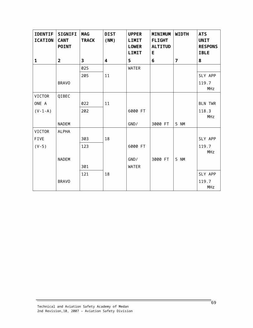
Attachment 18 Aircraft Type Designator
Note: L : land plane J : jet engined A : amphibian 1-8 : number of engine H : helicopter Speed: max cruising speed at or
above 10,000 feetP : piston enginedT : turbine engines Blank: nil data (unavailable)
Aircraft Type Designator
DESIGNATOR NAME OF MODEL MTOW SPEED MANUFACTURER
CIVIL MILI DESC (KG) (KTS)- A1 Skyraider L1P/M McDonnel Douglas,
US- A3 Skywarrior L1J/M McDonnel Douglas,
US- A4 Skyhawk L1J/M 11,113 581 McDonnel Douglas,
US- A6 Intruder L2J/M 27,500 595 Grumman Aviation,
USAC21 - Jet Commander L2J/M 9,298 471 Rockwell Intl, USAAC50 - Aerocommander
50L2P/L 3,175 178 Rockwell Intl, USA
AC88 U4 Supercommander L2P/L - - Rockwell Intl, USAA6T - Turbocommander L2T/L 4,285 241 Rockwell Intl, USA- A37 Dragonfly L2J/L 6,320 440 Cessna Acts Co., US- AH1 Huey/Cobra H2T/L 4,309 190 Bell Heli. Co., USAN10 - Antonov 10 L4T/M 55,110 366 Antonov, Russian
Fed.AN12 - Arrtonov 12 L4T/M 81,000 324 Antonov, Russian
Fed.AN22 - Antonov 22 L4T/H 250,000 399 Antonov, Russian
Fed.AN24 - Antonov 24 L2T/M 21,000 243 Antonov, Russian
Fed.
AN30 - Antonov 30 L2T/M 28,500 294 Antonov, Russian Fed.
AN32 - Antonov 32 L2T/M 27,000 290 Antonov, Russian Fed.
Technical and Aviation Safety Academy of Medan 2nd Revision, 10, 2007 – Aviation Safety Division69

DESIGNATOR NAME OF MODEL MTOW SPEED MANUFACTURER
CIVIL MILI DESC (KG) (KTS)AN72 - Antonov 72 L2T/M 33,000 422 Antonov, Russian
Fed.AN4C - Antonov
324/CondorL4J/H 385,560 500 Antonov, Russian
Fed,AN4R - Antonov
124/RusianL4J/H 405,909 500 Antonov, Russian
Fed.AN5M _. Antonov 225/Mirya L6JH 421,350 525 Antonov, Russian
Fed.- JET Alphajet L2J/L 6,550 450 Dassault-Breguet, Fr.AT42 - ATR 42 L2T/M 16,750 272 Aerospatiale, Fr.AT72 - ATR 72 L2T/M 19,990 294 Aerospatiale, Fr.- B1 Bomber B-1 L4J/H 181,450 1262 Rockwell Intl, USA- B52 Stratofortress L8J/H 221,350 565 Boeing Co. USAB707 - B707-100/200 L4J/M 116,575 537 Boeing Co. USAB707 - B707-300/400 L4J/M 120,750 535 Boeing Co. USAB717 - B717 L2J/M 63503 456 Boeing Co. USAB727 - B727-All Series L3J/M 95,000 527 Boeing Co., USAB72S - B720B L4J/M 106,000 520 Boeing Co., USAB737 T43A B737-100/200 L2J/M 52,400 509 Boeing Co., USAB73F - B737-400 L2J/M 55,600 525 Boeing Co., USAB735 - B707-300/500 L4J/M 60,000 520 Boeing Co., USAB747 E4A B747-100/200 L4J/M 371,000 528 Boeing Co., USAB744 B747-400 L4J/M 380,000 532 Boeing Co., USAB74S B747-300 L4J/M 370,000 535 Boeing Co., USAB757 B757 L2J/M 99,790 509 Boeing Co., USAB767 B767 L2J/M 136;080 497 Boeing Go., USAB777 B777 L2J/M Boeing Co., USABA11 BAC One-eleven L2J/M 45,000 470 BAE. Ltd., UKBA32 Jetstream 32 L2T/L - BAE. Ltd., UKBA46 BAE 146-100/200 L4J/M 42,184 437 Sae. Ltd., UKBATP Adv. Turbo. Prop. L2T/M 22,453 272 Bee. Ltd., UKBE10 U21 F King Air 100A L2T/L 5,667 245 Beechcraft Co. USABEIE C45 Twin Beech 18 LZT/L 4,490 180 Beechcraft Co. USA.B1B King Air 100B L2T/L 6,050 235 Beehcraft Co. USABE20 Super King Air L2T/L Beechcraft Co. USA
SE23 Sundowner L1 P/L Beechcraft Co. USA
Technical and Aviation Safety Academy of Medan 2nd Revision, 10, 2007 – Aviation Safety Division70

DESIGNATOR NAME OF MODEL MTOW SPEED MANUFACTURER
CIVIL MILI DESC (KG) (KTS)BE36 Bonanza L1 P/L 1,633 170 Beechcraft Co. USASE45 T34 Mentor L1 P/L 1,703 180 Beechcraft Co. USASE55 T42 Baron 55 L2P/L 2,449 200 Beechcraft Co. USABE58 Baron 58; D L2P/L 2,449 200 Beechcraft Co. USABE30 U8F Queen Air 80 L2P/L 3,992 195 Beechcraft Co. USABE90 - U21A King Air L2T/L 5,667 248 Beechcraft Co. USABE95 Travellair L2P/L - - Beechcraft Co. USABH06 H139 Jet Ranger H1T/L 1,451 118 Bell Helicopter, USABH13. - Sioux/
Trooper47G/JH1P/L 1,338 73 Bell Helicopter, USA
BH41 - Bell 412 H2T/L 5,397 133 Bell Helicopter, USABN2 BN2a Islander L2P/L 2,993 140 Britten Norman, UKBN3 BN3 Trilander L3P/L 4,241 156 Britten Norman, UK- BUC Buccaneer L2J/M 28,123 560 Hawker Siddley, UKC150 - Cessna 150 L1P/L 726 102 Cessna Acft Co.,
USAC172 T41 Cessna Skyhawk L1P/L 1,519 124 Cessna Act Co., USAC175 - Cessna Skylark L1P/L 1,519 124 Cessna Acft Co. USAC177 - Cessna Cardinal L1P/L 1,525 128 Cessna Acft Co.,
USAC180 - Cessna 180 L1P/L 1,498 122 Cessna Act Co., USAC182 - Cessna Skylane L1P/L 1,338 136 Cessna Acit C o.,
USAC185 - Cessna Skywagon L1P/L 1,496 135 Cessna Acft Co. USAC206 - Cessna 206 L1P/L 1,724 138 Cessna Act Co., USAC210 - Cessna Centurion L1P/L 1,723 163 Cessna Acft Co. USAC310 - Cessna Three-ten L2P/L 2,710 163 Cessna Acct Co.,
USAC337 - Cessna
SkymasterL2P/L 2,677 140 Cessna Act Co., USA
C401 - Cessna 401 L2P/L 2,857 189 Cessna Acft co., USAC402 - Cessna 402 L2PlL 2,857 192 Cessna Acft Co.,
USA0414 - Cessna 414 L2P/L 3,375 200 Cessna Acft Co. USAC425 - Cessna Corsair L2T/L 3,033 230 Cessna Acft Co. USAC441 - Cessna 441 LZT/L 3,379 234 Cessna Acct Co.,
USAC500 - Cessna Citation L2JIL 5,210 348 Cessna Act Co., USA
Technical and Aviation Safety Academy of Medan 2nd Revision, 10, 2007 – Aviation Safety Division71

DESIGNATOR NAME OF MODEL MTOW SPEED MANUFACTURER
CIVIL MILI DESC (KG) (KTS)0500 - Cessna Citation
M3L2J/M 9,5.26 486 Cessna Acft Go.,
USAC501 - Cessna Citation I L2J/L 5,210 340 Cessna Acft Co.,
USACW2 - Cessna Citation V L2J/L 9,550 486 Cessna Acft Co.,
USAC20A - Gutfstream III L2J/M - - Gulfstream AS, USA- C135 Stratolifter L4J/H 134,715 462 Boeing Co., USA- C5A Galaxy L4J/H 380,454 450 Lockheed, USA- C130 Hercules L4T/M 70,308 327 Lockheed, USA- C 141 Starlifter L4J/H 155,909 510 Lockheed, USACD22 - Nomad
FloatrmasterL2T/L 4,050 180 Govt Acft Co.
AustraliaCD24 - Nomad
SearchmasterLZTIL 4,1201 190 Govt Act Go.
AustraliaCL60 - Challenger L2J/M 18,643 472 Canadair CanadaCL61 - Canadair CL601 L2J/M 19,550 472 Canadair CanadaCN35 - CN 235 L2T/M 13,000 245 CASAAPTN,
IndonesiaCONC - Concorde L4J/H 182,000 M2.05 BAC/AerospatiaIe
UK/FranceCS01 E25 Aviojet L1 J/L 6,300 463 CASA, EspanaCS12 T12 CASH Aviocar L2TIL 7,450 208 CASA, EspanaCV60 - Convair 600 L2T/M 24,.450 261 Convair Div. GE,
USACV64 - Convair 640 L2T1M 24,950 265 Convair Div. GE,
USACV88 - Convair 880 L4J/M 87,410 492 Convair Div. GE,
USACV99 - Convair
990/Corona-L4J/M 114,790 504 Convair Div. GE,
USA- CNBR Canberra L2J/M 24,945 504 British Acft Co., UKDA01 - Mercure 100 L2J/M 85,000 503 Dassauft-Breguet Fr.DA10 - Falcon 10 L2J/M 8,300 M0.87 Dassautt-Bn3guet,
Fr.DA20 - Falcon 20 L2J/M 13,000 465 Dassauft-Breguet Fr.DA50 - Falcon 50 L2J/M 16,250 475 Dassauft-Breguet Fr.DA90 - Falcon 90 L2J/M 20,640 495 Dassauft-Breguet Fr.DC3 C47 Dakota/Skytrain L2P/M 12,700 160 McDonnel Douglas,
US
Technical and Aviation Safety Academy of Medan 2nd Revision, 10, 2007 – Aviation Safety Division72

DESIGNATOR NAME OF MODEL MTOW SPEED MANUFACTURER
CIVIL MILI DESC (KG) (KTS)DC8 - DC8 L4J/H 158,750 520 McDonnel Douglas
USDC9 DC 9 L2J/M 54,900 487 McDonnel Douglas
USDC10 DC10 L3J/H 251,000 495 McDonnel Douglas
USDH4 CC08. Caribou DHC-4 L2P/M 12,500 230 De Havilland,
CanadaDH5 GT15 Buffalo DHC5 LZT/M 13,250 255 De Havilland,
CanadaDH6 - Twin Otter DH6 L2T/L 5,670 182 De Havilland,
CanadaDH7 Dash Seven L4T/M 19,995 236 De Havilland,
CanadaDH8 - Dash Eight L2T/M 13,835 278 De Havilland,
Canada- E1 Tracer/Tracker L2P/M 13,222 230 Grumman, USA- E2 Hawkeye L2T/M 23,335 315 Grumman, USA- E135 Boeing EC135 L4J/M 134,715 462 Boeing Co., USA- E137 Boeing VC137 L4J/M 134,715 462 Boeing Co., USA- E3A AWACS L4J/M 116,000 520 Boeing Co. USA- EA6 Bomber L2J/M 26,535 595 Germany- ETAR Etendard L1J/M 10,275 585 Dassault-Breguet, Fr.EA30 - Airbus 300 L2J/H 137,000 505 Airbus Industry,
FranceEA31 - Airbus 310 L2J/H 138,600 500 Airbus Induxtry,
FranceEA32 - Airbus 320 L2J/H - - Airbus Industry,
FranceEA33 _ Airbus 330 L2J/M Airbus Industry,
FranceEA34 Airbus 340 L4J/H 160,000 500 Airbus Industry,
FranceFK10 - Fokker100 L2J/M 40,000 M0.75 Fokker-VFW. BV
NetherlandFK27, Folder Friendship L2T/M 20,820 260 Fodcer-VFW, BV
NetherlandFK28 Fokker Fellowship L2J/M 33,112 485 Fokker-VFW, BV
NetherlandFK50 Fokker 50 L2T/M 18,990 295 Fokker-VFW, BV
Netherland
Technical and Aviation Safety Academy of Medan 2nd Revision, 10, 2007 – Aviation Safety Division73

DESIGNATOR NAME OF MODEL MTOW SPEED MANUFACTURER
CIVIL MILI DESC (KG) (KTS)FK70 Fokker 70 L2J/M - - Fokker-VFW, BV
NetherlandF1 Mirage L1 J/M 14,900 1259 Dassautt-Breeguet,
Fr.- F4 Phantom L2J/M 26,035 1262 McDonnel Douglas
US- F5 Tiger L2J/M 15,875 917 Grumman, USA- F6 Delta Dart L1J/M 15,875 1324 Convair Div. GE.,
USA- F8 Crusader LIJ/M - - Convair Div.Ge.,
USA- F14 Tomcat LIJ/M 30,028 1149 Grumman, USA
F15 Eagle L2J/M 30,843 1146 McDonnel Douglas US
F16 Fghting Falcon L1J/M 16,057 M0.93 General Dynamic, USA
F18 Hornet L2J/M 25,400 M1.80 General Dynamic, USA
- F20A Tigershark LIJ/M 25,402 M2.00 Northtrop, USA- F86 Sabre L1J/M 9,350 597 Rockwell inU, USA- F100 Super Sabre LIJ/M 40,000 M0.75 Rockwell Inti, USA- F101 Voodoo L1J/M 21,090 1059 McDonnel Douglss
US- F102 Delta Dagger LIJ/M 14,515 716 Convair Div. GE,
USA- F104 Starfighter L1J/M 14,060 1259 Lockheed, USA- F105 Thunderchief LIJ/M 16,350 1240 Fairchild Ind., USA- F106 Delta Dart LIJ/M 15,875 1324 Convair Div. GE,
USA- F111 Bomber F-111 L2J/M 41,500 1433 General Dynamic,
USAG64 U16 Albatrns A2P/M 15,800 176 Grumman USA6159 C4 Guffstream L2T/M 15,920 302 Grumman, USAG2 - Gufstream I L2J/M 28,22 511 Grumman, USAG4 - Gulfstream IV L2J/M 31,616 M0.85 Grumman, USA- GNAT Gnat F141/144 L1J/L 3,010 603 Hawker Siddeley. UKHE1 - Hello Courier LlP/L 1,542 143 Hello Acft, USAH3 - Super Courier L1P/L 1,542 150 Hello Acct, USAHN32 - Alouette III HIT/L 2,250 119 SNIAS, France.
Technical and Aviation Safety Academy of Medan 2nd Revision, 10, 2007 – Aviation Safety Division74

DESIGNATOR NAME OF MODEL MTOW SPEED MANUFACTURER
CIVIL MILI DESC (KG) (KTS)HS21 - Trident, All Marks L3J/M 13,580 520 HS Aviation, UKHS25 - HS125 L2J/M 12,430 450 HS Aviation, UKHS74 Andover LZT/M 20,182 242 HS Aviation, UKHU50 H6 Hugh Pawnee HIT/L 1,157 117 Hughes Tools, USAHV34 H47 Chinook HZT/M 20,845 123 Boeing VERTOL,
USA- H53 Sea Stallion H2T/M 19,050 170 Sikorsky, USA- HAR Harrier L1J/M 11,339 640 British Acft, UK
SHAR Sea Harrier L1J/M 11,612 645 British Acft, UKHAWK Hawk L1J/M 8,342 555 British AMU UK
- HUN Hunter: L1J/M 10, 885 616 British Acct, U KIL14 - llyushin 14 L2P/M 18,000 162 Ilyushin, Russian
Fed.IL18 - Ilyushin 13 L4T/M 61,200 364 Ilyushin, Russian
Fed.IL28 - Ilyushin 28/Beagle L2J1M 21,000 485 Ilyushin, Russian
Fed.IL33 - llyushin 38/May ' L2T/M 63,500 347 Ilyushin, Russian
Fed.IL62 - Ilyushin 62 L4J/IH 162,000 486 Ilyushin, Russian
Fed.IL76 - Ilyushin 76 L4J/H 157,000 458 Ilyushin, Russian
Fed.IL66 - Ityushin 86rarnber L4J/H 206,000 528 Ilyushin, Russian
Fed.IL96 - Ilyushin 96 L4J/H 235,000 525 Ilyushin, Russian fed.- JAGR Jaguar L2J/M 14,500 860 British Acft, UK- KC10 DC10-Tanko; L3J/H 208,211 490 McDonnel Douglas
US- KC97 Stratofreighter L4P/M 79,450 325 Boeing Acft CO.,
USA- KC135 Stratotanker L4J/H 134,715 462 Boeing Acft Go., USAL101 - Lockheed Tri-star L3J/H 225,000 M0.85 Lockheed, USAL188 P3 Electra/Orion L4T/M 52,664 352 Lockheed, USAL329, C46 Jetstar L4T/M 19,051 495 Gates Learjet USAL382 C130 Hercules L4T/M 70,308 327 Gates Learjet USALR23 - Learjet 23 L2J/L 6,803 441 Gates Learjet USALR25 - Learjet 25 L2J/L 6,803 441 Gates Learjet USALR35 - Learjet 35 L2J/M 6,904 450 Gates Learjet, USA
Technical and Aviation Safety Academy of Medan 2nd Revision, 10, 2007 – Aviation Safety Division75

DESIGNATOR NAME OF MODEL MTOW SPEED MANUFACTURER
CIVIL MILI DESC (KG) (KTS)LR54 - Learjet 54 L2J/M 10,600 425 Gates Learjet USALR55 - Learjet 55 L2J/M - - Gates Learjet USA- LTNG Lightning L2J/M 21,770 1148 British Acft; UKMBH5 - Boelkow 105A H2T/L 2,300 125 MBB, GermanyMBK7 - Boelkow-
KawasakiH2T/L 2,800 152 MBB/
Kawasafd, ,Japan
MD11 - MD 11 L3J/H 285,990 525 McDonne! Douglas US
MD80 - MD-80 L2JIM 63,503 456 McDonnel Douglas US
- MI 17 Mig 17/Fresco L1J/L 6,069 617 Mikoyan, Russian Fed.
- MI 19 Mig 19/Farmer L2J/M 8,700 783 Mikoyan, Russian Fed.
- MI 21 Mig 21Fishbed LIJ/M 8,200 1203 Mikoyan, Russian Fed.
- MI 23 Mig 23/ L1J/M 12,70 1233 Mikoyan, Russian, Fed.
- MI 25 Mig 25/Foxbat L2J/M 29,120 1836 Mikoyan, Russian Fed.
- MI 27 Mig 271FIogger LIJ/M 20,410 M0.95 Mikoyan, Russian Fed.
- MI 29 Mig 29/Fulcrum L2J/M 16,330 1358 Mikoyan, Russian Fed.
- MI 31 Mig 31/Foxhound L2J/M 29,575 M2.20 Mikoyan, Russian Fed.
- MIRI Mirage I L1J/M 14,900 1259 Dassauft-Breguet, Fr.- MIR2 Mirage 2000 LIJ/M 15,000 1386 Dassauft-Breguer,Fr.- MIR3 Mirage III LIJ/M 13,500 1258 Dassauft-Bneguet,
Fr.- MIR4 Mirage IV L2J/M 31,600 1262 Dassauft-Breguet, Fr.- MIR5 Mirage V LIJ/M 13,500 1258 Dassauft-BregueL Fr.- MRC Tornado L2J/M 18,140 1146 Dassauft-2reguet, Fr.NAS2 Superpuma H2T/M 9,000 102 SNIAS, FranceNB05 - Boelkow B0105 H2T/L 2,300 125 IPTN, IndonesiaNB12 - Bell 412 H2T/M 5,347 133 IPTN, IndonesiaNC12 CAS, Aviocar L2T/M 7;450 208 IPTN, IndonesiaND16 - TransaA C160 L2T/M 52,090 250 SNIAS, FranceNSAO - Puma SA330 H2T/M 6,700 147 IPTN, Indonesia
Technical and Aviation Safety Academy of Medan 2nd Revision, 10, 2007 – Aviation Safety Division76

DESIGNATOR NAME OF MODEL MTOW SPEED MANUFACTURER
CIVIL MILI DESC (KG) (KTS)- NIM Nimrod L4J/M 87,090 500 Hawker Siddeiey, UK- OV1 Mohawk L2T/M 8,214 265 Rockwell Irtti, USA- OV10 Bronco L2T/L 6,563 244 Rockwell Inti, USAPA23 Apache L2P/L 2,177 166 Piper Act Co., USAPA24 - Commanche L1P/L 1,451 165 Piper Acct Co., USAPA25 - Pawnee L1P/L 1,365 155 Piper Act Co., USAPA28 T35 Cherokee L1P/L 1,202 143 Piper Acft Co., USAPA30 - Twin Commanche L2P/L Piper Acft Co., USAPA31 Navajo/Mojave L2P/L 2,812 185 Piper Acit Co., USAPA34 Seneca L2P/L 3,800 162 Piper Acft Co., USAPA38 - Tomahawk L1P/L - - Piper Acft Co., USAPA41 - Cheyenne L2T/L 5,486 362 Piper AcftCo., USAPA44 - Seminoie L2P/L - - Piper Acft Co., USAPA46 - Malibu L1P/L 1,746 270 Piper Acft Co., USAPASE - Seneca II L2P/L 3,800 162 Piper AcftCo., USAPAZT U11 Aztec L2P/L 2,360 182 Piper Acft Co., USA- P2 Neptune L2P/M 36,240 309 Lockheed, USA- P3 Orion L4T/M 52,664 352 Lockheed, USA- PML Tornado L2J/M 25,402 M2.20 Northtrop, USA- PROV Jet Provost LIJ/M 5,215 410 British Acft Co., UKS210 - CaraveLte,All
SeriesL2J/M 58,000 445 SNIAS, France
S315 - Lama SA315 H1T/L 1,951 113 SNIAS, FranceS316 A103 Alouette III H1T/L 2,200 115 SNIAS, FranceS318 - Alouette II H1T/L 1,650 102 SNIAS, FranceS319 - Alouette III S319 H1T/L 2,250 119 SNIAS, FranceS321 SFRL Super Frelon H1T/M 13,000 135 SNIAS, FranceS330 - Puma SA330 H2T/L 6,700 147 SNIAs, FranceS332 - Super Puma
AS332H2T/M 9,000 102 SNIAs, France
S341 - Gazelle SA341/342
H1T/L 1,800 168 SNIAS, France
S351 - Ecureuil A351 HIT/L 4,980 155 SNIAS, FranceS360 - Dauphin SA360 H1T/L 3,000 170 SNIAS, FranceSB32 J32 SAAB 32/Lausen L1J/M 13,000 608 SAAB Scania,
Sweden
Technical and Aviation Safety Academy of Medan 2nd Revision, 10, 2007 – Aviation Safety Division77

DESIGNATOR NAME OF MODEL MTOW SPEED MANUFACTURER
CIVIL MILI DESC (KG) (KTS)SB35 J35 SAAB 35IDraken L1J/M 16,000 1146 SAAB Scania,
SwedenSB37 J37 SAAB 37/VIggen LIJ/M 16,000 1146 SAAB Scania,
SwedenSK58 H35 Choctaw/
SeahorseH1P/L 6,350 110 Sikorsky Acft Div.
USASK59 - Sikorsky S59 H1P/L 5,896 115 Sikorsky Acft Div
USASK61 - Seating S61. H2TIM 8,450 144 Sikorsky Acft Div.
USASK62 H52 Sikorsky S62' H1T/M 8,620 140 Sikorsky Acft Div.
USASK64 H54 Skycrane S64 H2T/M 19,050 110 Sikorsky Acct Div.
USASK70 - Sikorsky S70 H2T/M 9,977 159 Sikorsky Acft
Div.USASK76 - Sikorsky S76 H2T/L 5,307 155 Sikorsky Acft Div.
USA- S34 Viking L2J/M 19,277 440 Lockheed, USA- SR71 Blackbird L2J/M 77,110 1720 Lockheed, USA- SU78 Sukhoi 7/Filler L2J/M 13,500 917 Sukhoi, Russian Fed.- SU9 Sukhoi 9/Fishpot LIJ/M 12,750 1033 Sukhoi, Russian Fed.- SU11 Sukhoi 11/Flagon L2J/M 16,000 1320 Sukhoi, Russian Fed- SU22- Sukhoi 22/Fitter LIJ/M 17,700 1275 Sukhoi, Russian Fed.- SU24 Sukhoi 24/Fencer L2J/M 29,500 1359 Sukhoi, Russian Fed.- SU25 Sukhoi
25/FrogfootL2J/M 16,785 465 Sulchoi, Russian
Fed.- SU27 Sukhoi 271Flanker L2J/M 28,805 802 Suldhoi, Russian
Fed.- TU16 Tupoiev
16/BadgerL2J/M 68,000 510 Tupolev Russian Fed
- TU22 Tupolev 22/Blinder L2J/M 83,900 800 Tupolev Russian Fed- TU22
MTu22M/Backfire L2J/M 123,350 1430 Tupolev Russian Fed
- TU28 Tupolev 28Fiddler L2J/M 45,000 1000 Tupolev Russian Fed- TU34 Tupolev 134 L2J/M 44,500 469 Tupolev Russian Fed- TU44 Tupolev 144 L4J/H 180,000 1350 Tupolev Russian Fed- TU54 Tupolev 154 L3J/M 90,000 526 Tupolev Russian Fed- TU95 Tupolev 95Bear L4J/H 154,220 434 Tupolev Russian Fed- TU114 Tupolev 114/Moss L4J/H 163,295 400 Tupolev Russian Fed
Technical and Aviation Safety Academy of Medan 2nd Revision, 10, 2007 – Aviation Safety Division78

DESIGNATOR NAME OF MODEL MTOW SPEED MANUFACTURER
CIVIL MILI DESC (KG) (KTS)VC8 - V'ickers-Viscount
800L4T/M 32,886 306 British Acct C. UK
VC9 - Vanguard 952/953 L4T/M 66,445 369 British Acft Co., UKVC10 - VC-Ten 1100 , L4J/H 141,000 505 British Acfi Co. UKVC15 - Super VC10-1150 L4J/H 151,000 ' 510 British Act Go. UK- VLCN Vulvan L4 J/M 81,645 542 British Act Co., UKYK40 - Yak-40 L3J/M 43,256 425 Yakoviev Russian
Fd.YK42 - Yak-42 L3J/M 45,562 432 Yakoviev Russian
Fd.YS11 - YS 11/YS 11-A L2T/M 25,000 252 Nihon Aeroplane Jap.
Technical and Aviation Safety Academy of Medan 2nd Revision, 10, 2007 – Aviation Safety Division79

Attachment 19 Control Abbreviation
Table 1 Control Abbreviation
ABBREV
MEANING ABBREV
MEANING
ABM abeam MA missed approachAPT airport PT procedure turnAPCH any authorized/approved/
authorised IAPR radial (when preceded by an
Identification and three figures)
ASC ascent or ascend to RL leavingBC back course RLS releaseBT base turn RP report passingBDRY boundary RR report reachingDCT direct RX report crossingDLA delay SI straight-in-approachEAT expected approach time SYD release subject to your
discretionEFC expect further clearance SYT release subject to your own
trafficFPM feet per minute TL turn leftH holding TR turn rightHFR hold for release UFA until further adviceILS ILS approach UFC urn further clearanceM magnetic (when preceded by
three figures)VA visual approach
VR VOR approach
Technical and Aviation Safety Academy of Medan 2nd Revision, 10, 2007 – Aviation Safety Division80

Attachment 20
Control Symbol
Symbol Meaning Symbol Meaning Symbol Meaning
Climb(ing) toEnter control zone**
Special VFR operation in the vicinity of AD
Descend(ing) toLeaving control zone**
Pilot cancelled FPL
CruiseThrough control zone
Information/flight data has been passed to recipient and correctly read back
@ At Local flight DME holdIng (use mileage)
Cross Abeam No delay expected
MaintainDepart (direction/turn after takeoff)
Contact …(ATS unit) on …. (frequency – if other than standard)
Cross airway/route/course
Until (After passing)
> before
Intercept airway/route/course
( ) Alternate instruction
< after
While in controlled airspace
( ) restriction At or before
While in control area
At or above At or after
Enter controlled area** At or below
Technical and Aviation Safety Academy of Medan 2nd Revision, 10, 2007 – Aviation Safety Division81
25
C
w

Symbol Meaning Symbol Meaning Symbol Meaning
Leaving controlled area**
_____ From - to
Note: ** arrows indicate direction of flight
Not below (the level indicated)
Proceeding VFR at the time indicated
Precautionary Holding instructions issued
Not above (the level indicated)
Holding instructions issued (aircraft in the air) or an indication that the aircraft to be held on the ground awaiting a release.
Overflight (flight passing over aerodrome without landing)
Not before the time indicated
Aircraft holding
____210190
Aircraft operating between the two levels indicated
Coordinated descent (or climb when an upward arrow is used)
Aircraft has left the holding pattern
Technical and Aviation Safety Academy of Medan 2nd Revision, 10, 2007 – Aviation Safety Division82

Attachment 21
LETTER OF AGREEMENTBETWEEN SELAYANG ACC, SELAYANG APP AND PADANG BULAN TWR
1. SUBJECT : ATC CO-ORDINATION PROCEDURES
2. UNITS INVOLVED : a. SELAYANG AREA CONTROL CENTRE b. SELAYANG APPROACH CONTROL OFFICE
c. BULAN AERODROME CONTROL TWR
3. PURPOSE:The purpose of this letter of agreement is to define co-ordination and transfer of responsibility procedures in respect of aircraft operating within SLY CTR and SLY CTA to ensure a safe, expeditious and orderly flow of air traffic.
4. SCOPES:Involved in these procedures are the following items.
a. Area of Jurisdiction;
b. Exchange of flight data;
c. ATC Clearance; and
d. Transfer of responsibility.
5. AREA OF JURISDICTION5.1 Area of jurisdiction of Bulan Tower (BLN TWR)
a) lateral limit : a circle with a radius of 17 NM centred at ARP, 03:33:33N 098:40:16 E
b) vertical limit : - upper limit : 3,000 feet. - lower limit : ground/water.
5.2 Area of jurisdiction of Selayang Approach Control Office (SLY APP)
lateral limit : a. circle with a radius of 40 NM centred at BUlan radar head (03:33:16.08N; 098:40:13.80E), excluding the area allocated to BLN TWR
a) vertical limit : - upper limit : 10,000 feet - lower limit : ground/water.
5.3 Area of jurisdiction of SELAYANG Control Center (SLY ACC)
a) lateral limit : -QIBEC (04:40:19.99N, 109:37:46.19E), - ROMEO (07:44:03.99S, 109:39:22.89E) thence along an arc of the circle with a radius of 200 NM centred at SELAYANG radar head (06:13:16.08S; 106:40:13.80E) clockwise to QIBEC, except as allocted to BLN TWR and SLY APP.
b) vertical limit : - upper limit: F460.
- lower limit: 6000 feet except above SLY CTR is 10,000 feet.
Technical and Aviation Safety Academy of Medan 2nd Revision, 10, 2007 – Aviation Safety Division83

6. EXCHANGE OF FLIGHT DATA6.1. Arrival
1.1 SLY ACC shall keep the SLY APP promptly advised of pertinent data such as
1.2 ETA of arriving aircraft (at least 15 minutes before ETA including ACID, type, point of departure and destination),
a) estimated and proposed level of aircraft will be transferred,
b) transfer of control time, position and altitude,
c) EAT that has been issued by ACC to aircraft,
d) expected delay for departure due to congestion,
e) any other pertinent information.
1.3 SLY APP shall keep the BLN TWR promptly advised of pertinent data such as:
a) estimated time and proposed level of arriving aircraft over aerodrome;
b) statement that an aircraft has been cleared to contact BLN TWR;
c) anticipated delay departure traffic due to congestion.
1.4 BLN TWR shall keep the SLY APP promptly advised of pertinent data such as
a) arrival time, if necessary;
b) statement that arriving aircraft is in communication with and sighted by BLN TWR;
c) all available information relating to overdue aircraft;
d) information concerning missed approach.
6.2. Departure
1.5 BLN TWR shall keep the SLY APP promptly advised of pertinent data such as:
a) information that aircraft ready for push back/start engine;
b) information that aircraft (IFR) ready for departure (request release time);
c) information concerning aircraft that constitute essential traffic to aircraft under the jurisdiction of SLY APP;
d) information that departure aircraft can not depart in accordance with clearance expiry time (CET);
e) departure time/airborne time and route to be flown;
f) any other pertinent information
1.6 SLY APP shall keep the SLY ACC promptly advised of pertinent data such as:
a) lowest vacant level available at individual. fix;
b) departure time;
Technical and Aviation Safety Academy of Medan 2nd Revision, 10, 2007 – Aviation Safety Division84

c) missed approach, if it is considered to constitute a conflict to traffic under SLY ACC;
d) EAT and revision thereof;
e) any other pertinent information
7. AIR TRAFFIC CONTROL CLEARANCE7.1 Request and Clearance delivery
1.7 BLN TWR request clearance to SLY APP then SLY APP request clearance to SLY ACC.
1.8 SLY ACC shall issue ATC clearance subject to traffic under its jurisdiction to SLY APP and SLY APP relay ATC clearance to BLN TWR with the additional clearance subject to traffic under control of SLY APP.
7.2 Content of ATC clearance
1.9 The content of ATC, clearance consists of:
a clearance limit;
b route of flight;
c level;
d departure instruction, and
e any other instruction/information.
Example: GIA483 CLEARED TO PDG VIA W-11 F240 AFTER TAKE-OFF TURN LEFT TRACK 090 DEGREES MAGNETIC TO INTERCEPT W-11 MAINTAIN 2000 FEET
8. TRANSFER OF CONTROL8.1 Departure
1.10 Departing (IFR) aircraft will be transferred from BLN TWR to SLY APP immediately after airborne and clear of other traffic, except in weather below minima (IMC), will be transferred before entering runway in use.
1.11 Departing (VFR) will be transferred from BLN TWR to SLY APP at altitude 3000 feet.
1.12 Unless prior co-ordination, SLY APP shall not climb outbound traffic higher than 10,000 feet.
1.13 Departing traffic will be transferred from SLY APP to SLY ACC at SLY CTR BDRY or at any point/time/level agreed by the two units.
8.2 Arrival
1.14 Arrival (IFR) will be transferred from SLY APP to BLN TWR when the aircraft is passing instrument approach fix (IAF) inbound at 2000 feet (SLY VOR/DME) or on ILS slope (ON NDB).
Technical and Aviation Safety Academy of Medan 2nd Revision, 10, 2007 – Aviation Safety Division85

Note: The transfer of control shall normally be effected when the arriving aircraft has reported visual contact, however, for the interest of avoiding unexpected overshooting due to unavailability of landing clearance delivery, the transfer effected is the transfer of air-ground communication only. It is therefore, the subsequent aircraft which will be cleared to make instrument approach after SLY APP has obtained information from BLN TWR that arriving aircraft has reported visual contact.
1.15 Arriving (VFR) will be transferred from SLY APP to BLN TWR at ELAWA/BINJA/STAGI (for traffic from the north/west/south or CEMIN/ORAWA (for traffic from east/southeast).
1.16 Unless prior co-ordination, SLY ACC shall not descend inbound traffic lower than 11,000 feet.
Arrival traffic will be transferred from SLY ACC to SLY APP at SLY CTR BDRY or at any point/time/level agreed by the two units.
9. DEVIATIONAny deviation from or change to the procedures contained in this letter of agreement may only be made with the concurrence and with the purpose to enhance the safe, expeditious and orderly movement of air traffic.
Selayang, 1st October 2007
Chief Of
SELAYANG APPROACH
CONTROL OFFICE
JULIET FOXTROT MIKE
Chief Of
BULAN AERODROME
CONTROL TWR
TANGO ALFA WHISKEY
Airport Authority of
PADANG BULAN INTERNATIONAL
AIRPORT
ALFA BRAVO FOXTROT
Chief Of
SELAYANG AREA CONTROL CENTRE
LIMA TANGO HOTEL
Technical and Aviation Safety Academy of Medan 2nd Revision, 10, 2007 – Aviation Safety Division86

Attachment 22
REFERENCES
1. Budi Pradana, Aminarno, SsiT, MM, “Seahorse-Batfish Air Traffic Control
Procedures (Non Radar)”, Indonesia Civil Aviation Institute, Curug, 2003.
2. Documents 4444, Air Traffic Management, ICAO, 2004
3. Annex 10 Vol 2, Aeronautical Telecommunication, ICAO, 2004.
4. ATC Licence and Aerodrome Control, Ambiji, Australia, 2002
5. Indonesian Location Indicator, Indonesia DGAC, April 2004
6. etc.
Technical and Aviation Safety Academy of Medan 2nd Revision, 10, 2007 – Aviation Safety Division87