120 series electric actuator series electric actuator 01.06.16 pib 2010 b 12 volt applications it is...
TRANSCRIPT

1
4.12(105)
3.50(89)
.28(7)
3.625(92)
1.00(25)
2.750(70)
.95(24)
2.375(60)
1.92(49)
3.69(94)
* .69(17.5)
4.75(116.1)
3.80(98.5)
3.62(92.0)
.85(21.6)
2.25(57.1)
1.81(48.0)
1.05(26.7)
.28 DIA(7)
2.05(52.1)
3.88(98.6)
* .69(17.5)
4.75(116.1)
3.80(98.5)
3.62(92.0)
.85(21.6)
2.25(57.1)
1.81(48.0)
1.05(26.7)
.28 DIA(7)
2.05(52.1)
3.88(98.6)
120 SeriesElectric Actuator
© 2016 Copyright All Rights Reserved120 Series Electric Actuator 01.06.16 PIB 2010 B
1
2
SELECTION CHART
SPECIFICATIONS
PERFORMANCE
Available Torque 1.0 ft-lb max (1.4 Nm) See Diagram 5
Max Operating Shaft Travel 25° ±1° CW/CCW
POWER INPUT
Operating Voltage 12 or 24 VDC
Normal Operating Current 2.0 Amps @ 12 VDC 1.0 Amps @ 24 VDC
Maximum Current Continuously Rated
6.0 Amps @ 12 VDC3.0 Amps @ 24 VDC
ENVIRONMENT
Operating Temperature Range -65°F to +200°F (-54°C to +95°C)
Relative Humidity up to 100%
All Surface Finishes Fungus Proof and Corrosion Resistant
PHYSICAL
Dimensions See Section 3
Weight 4.5 lb (2.05 kg)
Mounting Electrical connector at top preferred
RELIABILITY
Vibration Up to 20 G, 50 - 500 Hz
Testing 100% Tested
3 OUTLINE & DIMENSIONS
ACB120
4.12(105)
3.50(89)
.28(7)
3.625(92)
1.00(25)
2.750(70)
.95(24)
2.375(60)
1.92(49)
3.69(94)
ADB120 and ADC120 (and S)
[X.XX]X.XX
in[mm]
Dimension Units
TORQUE(Lb.-Ft.)
ANGLE (Deg.)
00
.5
1.0
5 10 15 2520
ADB/ADCDECREASE FUEL
(SPRING)
ADB/ADCINCREASE
FUEL
Graph of Actuator TorqueDIAGRAM 5 ACTUATOR TORQUE
Prod. #System Voltage Connector
Shaft HousingMIL Commercial Packard12 24 Multi
ACB120 ■ ■ Serrated Sand
ADB120 ■ ■ Serrated Die
*ADC120-12 ■ ■ Smooth Die
*ADC120-24 ■ ■ Smooth Die
ADC120S-12 ■ ■ Serrated Die
ADC120S-24 ■ ■ Serrated Die
*ADD120-12 ■ ■ Smooth Die
*ADD120-24 ■ ■ Smooth Die
ADD120S-12 ■ ■ Serrated Die
ADD120S-24 ■ ■ Serrated Die
* Historical Models Not Available For Purchase
2
AB
CD
E
F
to Actuator Terminal “A”on Speed Control Unit
to Actuator Terminal “B”on Speed Control Unit
DIAGRAM 3 12 VOLT OPERATION (MILITARY CONNECTOR)
AB
CD
E
F
to Actuator Terminal “A”on Speed Control Unit
to Actuator Terminal “B”on Speed Control Unit
Jumper B to C
DIAGRAM 4 24 VOLT OPERATION (MILITARY CONNECTOR)
24 VOLT APPLICATIONS
A simple jumper wire between pins B and C at the mating half connector can be made. The remaining two pins, A and D, can be extended to the required length. Maximum current is 4 Amps. The recommended wire size is at least #18 AWG (1.0 mm sq.). See Diagram 4.
Actuator cable harnesses with lengths greater than 10 ft. (3 meters) from the ac-tuator to the speed control unit may introduce current losses which can restrict full rotation of the actuator. In this case, use of a larger gauge wire is required. For applications where EMI is of concern, twisted, shielded cable for the actu-ator is recommended. Twisting of the cable alone will substantially reduce EMI.
5 WIRING
ADC Prewired for 12 or 24V. Mating hardware included (Commercial)
ADDCH1215 Packard Cable HarnessEC1300 Packard Mating Half
ACBADB
CH1203 - 12’ Military Straight HarnessCH1210 - 12’ Military 90° HarnessCH1212 - 30’ Military Straight HarnessEC1000 Military Straight ConnectorEC1010 Military 90° Straight Connector
The mating electrical connector must be wired in a configuration de-pendent on the system voltage supply. The maximum wire size that will fit into the actuator mating half connector is #16 AWG (1.3 mm sq.). Cable CH 1203/1210, a pre-wired actuator cable harness, is available. It is 12 feet (4 meters) in length and suitable for use on 12 or 24 volt systems. CH1212 is 30 feet (9.1 meters) in length.
A B A B
AB
CD
E
F
4.3 OHMS
3.4 OHMS
PACKARDCONNECTOR
COMMERCIALCONNECTOR
MILITARYCONNECTOR
Available Connector Options:
© 2016 Copyright All Rights Reserved120 Series Electric Actuator 01.06.16 PIB 2010 B
12 VOLT APPLICATIONS
It is preferable to connect four wires, one to each of the coils and wire per Diagram 3. Maximum current is 8 Amps. The recommend-
ed wire size is at least #16 AWG (1.3 mm sq.).
NOTE
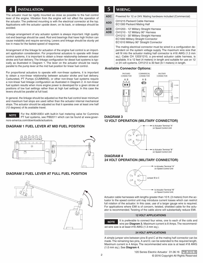
The actuator must be rigidly mounted as close as possible to the fuel control lever of the engine. Vibration from the engine will not affect the operation of the actuator. The preferred mounting is with the electrical connector at the top. Applications with the actuator upside down, on its back, or sideways should be avoided.
Linkage arrangement of any actuator system is always important. High quality rod end bearings should be used. Rod end bearings that have high friction can cause instability and require servicing. Levers and linkage should be sturdy yet low in mass for the fastest speed of response.
Arrangement of the linkage for actuation of the engine fuel control is an import-ant application consideration. For proportional actuators to operate with linear control systems, it is important to obtain a linear relationship between actuator stroke and fuel delivery. The linkage configuration for diesel fuel systems is typ-ically as illustrated in Diagram 1. The lever on the actuator should be nearly parallel to the pump lever at the mid fuel position for linear fuel control.
For proportional actuators to operate with non-linear systems, it is important to obtain a non-linear relationship between actuator stroke and fuel delivery. Carbureted, PT Pumps (CUMMINS), or other non-linear fuel systems require a non-linear fuel linkage configuration as illustrated in Diagram 2. A non-linear fuel system results when more engine power is developed for a given stroke at positions of low fuel settings rather than at high fuel settings. In this case the levers should be parallel at full load.
In general, the linkage should be adjusted so that the fuel control lever minimum and maximum fuel stops are used rather than the actuator internal mechanical stops. The actuator should be adjusted so that it operates over at least one half (12 degrees) of its available travel.
For the ADB120E4 with built-in fuel metering valve for Cummins PT fuel systems, see PIB2011 which can be found at www.gover-
nors-america.com/downloads/actuators.
4 INSTALLATION
DIAGRAM 1 FUEL LEVER AT MID FUEL POSITION
NOTE
DIAGRAM 2 FUEL LEVER AT FULL FUEL POSITION

3
7 TROUBLESHOOTINGIf the governor system fails to operate, make the following tests at the actuator mounted connector while moving the actuator through its stroke.
ACB/ADB120
TERMINALS RESISTANCE
A to B 4.2 Ohms
C to D 3.4 Ohms
A to C Infinity
A to Housing Infinity
C to Housing Infinity
Energize the actuator to full fuel (follow steps in control unit publication) and manually move the actuator through its range. No binding or sticking should occur. If the actuator passes the tests, the problem is elsewhere in the system. Refer to the control unit troubleshooting publication.
ADC/ADD 120
TERMINALS RESISTANCE
Red to White (12 V) 1.9 Ohms
Red to White (24 V) 7.5 Ohms
Red to Housing Infinity
White to Housing Infinity
MEASURING THE RESISTANCE
ADJUSTMENTS6Reconfirm that the linkage is not binding and that friction is minimal. Before starting the engine, push the actuator to the full fuel position and release. It should return instantly to the no fuel position without any binding. Once the engine has been started, the linkage can be optimized by temporarily inserting an ammeter in one of the wires between the speed control unit and the actuator or by measuring the voltage across the actuator. Measure the actuator current or voltage at no load and full load. The range and the starting current or voltage are important for optimizing the linkage system. Typical values are shown in the following table for 12 volt and 24 volt systems.
To increase the range of the actuator voltage or current, move the linkage to a lower hole on the actuator lever. A lower range of actuator current than suggest-ed can cause instability or poor performance. To increase or decrease the no load current or voltage, adjust the length of the link between the actuator and the engine fuel control. Smaller angles of actuator travel may improve transient performance, but will reduce available force at the fuel control lever. Allowing the actuator to operate through at least one half (12 degrees) of its stroke will usually provide near optimum response.
12 VOLTS 24 VOLTS
No Load 1.0 Amp, 2 Volts 0.5 Amps, 4 Volts
Full Load 2.5 Amp, 5 Volts 1.2 Amps, 10 Volts
ACTUATOR STARTING CURRENT/VOLTAGE RANGE CHART
© 2016 Copyright All Rights Reserved120 Series Electric Actuator 01.06.16 PIB 2010 B