(12) united states patent (io) patent no.: us 9,464,638 … compressor for automotive...
TRANSCRIPT

1111111111111111111111111111111111111111111111111111111111111111111111111111
(12) United States PatentCepeda-Rizo et al.
(54) REVERSE BRAYTON CYCLE WITHBLADELESS TURBO COMPRESSOR FORAUTOMOTIVE ENVIRONMENTALCOOLING
(71) Applicants:Juan Cepeda-Rizo, Long Beach, CA(US); Gani B. Ganapathi, LaCrescenta, CA (US)
(72) Inventors: Juan Cepeda-Rizo, Long Beach, CA(US); Gani B. Ganapathi, LaCrescenta, CA (US)
(73) Assignee: California Institute of Technology,Pasadena, CA (US)
(*) Notice: Subject to any disclaimer, the term of thispatent is extended or adjusted under 35U.S.C. 154(b) by 669 days.
(21) Appl. No.: 13/875,188
(22) Filed: May 1, 2013
(65) Prior Publication Data
US 2013/0294890 Al Nov. 7, 2013
Related U.S. Application Data
(60) Provisional application No. 61/641,132, filed on May1, 2012.
(51) Int. Cl.F04D 29/58 (2006.01)F25B 9/00 (2006.01)B60H 1/32 (2006.01)
(52) U.S. Cl.CPC ............. F04D 29/58 (2013.01); B60H 1/3204
(2013.01); F25B 9/004 (2013.01)(58) Field of Classification Search
CPC ..... F04D 29/58; B60H 1/3204; F25B 9/004;FO1D 1/34
(io) Patent No.: US 9,464,638 B2(45) Date of Patent: Oct. 119 2016
USPC ............................................................ 415/90See application file for complete search history.
(56) References Cited
U.S. PATENT DOCUMENTS
1,061,142 A 5/1913 Testa1,061,206 A 5/1913 Testa4,036,584 A 7/1977 Glass4,403,911 A * 9/1983 Possell .................. A61M 1/101
415/904,445,639 A * 5/1984 Kinsell ..................... F02C 6/00
237/816,174,127 BI * 1/2001 Conrad ..................... A47L 5/22
415/1
(Continued)
OTHER PUBLICATIONS
Beatrice et al., "Feasibility of a Brayton Cycle Automotive AirConditioning System," Engenharia Termica, vol. 8, No. 2, Dec.2009.
(Continued)
Primary Examiner Igor KershteynAssistant Examiner Aaron R Eastman(74) Attorney, Agent, or Firm Canady & Lortz LLP;Bradley K. Lortz
(57) ABSTRACT
An automotive cabin cooling system uses a bladeless tur-bocompressor driven by automobile engine exhaust to com-press incoming ambient air. The compressed air is directedto an intercooler where it is cooled and then to anotherbladeless turbine used as an expander where the air cools asit expands and is directed to the cabin interior. Excess energymay be captured by an alternator couple to the expanderturbine. The system employs no chemical refrigerant andmay be further modified to include another intercooler onthe output of the expander turbine to isolate the cooled cabinenvironment.
21 Claims, 6 Drawing Sheets
X-300
Intercooler X314E322 Engine
Turbine A Exhaust
308 310~ — — 1 —~
+P Comp. Turbine330L
J
306
EngineCombustion 304Gases
302
Air air312
https://ntrs.nasa.gov/search.jsp?R=20160013190 2018-06-02T09:57:38+00:00Z

US 9,464,638 B2Page 2
(56) References Cited
U.S. PATENT DOCUMENTS
6,224,325 B1 5/2001 Conrad et al.6,261,052 B1 * 7/2001 Conrad ................. F04D 17/161
415/906,368,078 B1 * 4/2002 Palumbo ................... FO1D 1/36
415/2026,503,067 B2 1/2003 Palumbo6,682,007 B2 1/2004 Noda et al.6,692,232 B1 * 2/2004 Letourneau ............... FO1D 1/36
415/906,726,443 B2 4/2004 Collins et al.7,125,439 B2 * 10/2006 Bennett ................ BO1D 53/047
95/2682005/0169743 Al* 8/2005 Hicks ..................... B82Y 30/00
415/902 00 8/004 1046 Al* 2/2008 Bering ...................... FO IN 5/02
60/320
2009/0260361 Al * 10/2009 Prueitt .................... FOIK 27/0060/670
2010/0139297 Al * 6/2010 McCormick ............ F25B 9/00462/89
2011/0239659 Al* 10/2011 Lior ....................... B60H 1/00460/783
Mutterer et al., "Alternative Technologies for Automobile Air
Conditioning," Air Cond. and Refrig. Center, U. of Illinois Urbana,
1991.
Carey, "Assessment of Tesla Turbine Performance for Small ScaleRankine Combined ... ," J. of Engineering for Gas Turbines andPower, ASME, Dec. 2010, vol. 132.
* cited by examiner

U.S. Patent Oct. 119 2016 Sheet 1 of 6 US 9,464,638 B2
1
1
Comp.
104 I
Air
Heat `114
Intercooler
0-100
Turbine x,--1 12
Net Work16 Output
-110
Cooled Air
FIG. 1
31,or--300
318 Intercooler --314322 Engine
Turbine Alt. Exhaust
308 310
+ _ ~-324 'Power ( Comp. Turbine
330 L — — —
328 306
EngineCombustion 304
I ~ Gases3
326 02
Cooled External
Air Air
312
FIG. 3A

Comp
ress
ed
214
Air
Ar—
Inpu
tAi
r
212
FIG.
2
b
Ar-214
A~--200 10
C
o-212
208 4*
206
/ o

31
Heat
Turbine M
Alt.
+11-,,,,-324
Power
Heat
Exchanger
Heat
x--350
Heat
,-314
Exch
ange
r En
gine
Exha
ust
308
310
I Comp.
Turbine
L ---
-~
Engine
Comb
usti
onGases
302
FIG. 38
M
382-)366
.--360
Wens
Heat
sink
f362
VC
364
380
384-
)~,-
JR
388
372
368
386
b woe
E
~.o it
370
C-Comapmmor
R-RecvPwdW
E - Twbbw
FIG. 3C
364
Heat
Reje
cted
IL
T
366
362
368
Turbine
372
Expansion
370 Av
ailable
Cooling
8
FIG. 3D
r, 0 a

U.S. Patent Oct. 119 2016 Sheet 5 of 6
Start
US 9,464,638 B2
Receive engine combustion gases in a first turbine of a bladelessturbocompressor to drive a first bladeless impeller coupled to a
second bladeless impeller of a compressor.
Receive and compress the air in the compressor by the secondbladeless impeller.
Receive the compressed air from the compressor and cool it withan intercooler.
Receive the cooled, compressed air from the intercooler andexpand it in a second turbine, the second turbine having a thirdbladeless impeller driven by the cooled, compressed air, the
cooled, compressed air expanding and becoming further cooledthereby.
End
FIG. 4
,x--400

U.S. Patent Oct. 119 2016 Sheet 6 of 6 US 9,464,638 B2
ae~V or-cam rQssien
Thmn Uab ios
SWUM Cy01a
wMemo torumAtr qJ010
Cosiaamt Cy010
eaeotm Air Cy01e
Absorption CgOu
0.00
FIG. 5A
Overall COP's of various systems
FIG. 5B
0.42
OAO
O.Ss
0" 1 AO

US 9,464,638 B2
REVERSE BRAYTON CYCLE WITHBLADELESS TURBO COMPRESSOR FOR
AUTOMOTIVE ENVIRONMENTALCOOLING
CROSS-REFERENCE TO RELATEDAPPLICATIONS
This application claims the benefit under 35 U.S.C. §119(e) of the following U.S. provisional patent application,which is incorporated by reference herein:
U.S. Patent Application No. 61/641,132, filed May 1,2012, and entitled "Reverse Brayton Cycle With BladelessTurbo Compressor For Automotive Refrigeration", byCepeda-Rizo et al.
STATEMENT OF GOVERNMENT RIGHTS
The invention described herein was made in the perfor-mance of work under a NASA contract, and is subject to theprovisions of Public Law 96-517 (35 USC 202) in which theContractor has elected to retain title.
BACKGROUND OF THE INVENTION
1. Field of the InventionThis invention relates to systems to provide environmen-
tal cooling in vehicle cabins, particularly in automobilecabins.
2. Description of the Related ArtEnvironmental heating and cooling systems for the
vehicle cabins are employed for most types of vehicles inorder to maintain the occupant comfort. Such systems areparticularly important in vehicles which are used to transportpeople through extreme weather and environmental condi-tions such as aircraft or automobiles. Cooling systems aretypically more complex than heating systems.
In automobile applications, main stream systems employa vapor compression cycle using freon R134a, etc. as theworking fluid in a closed system. In the well known system,freon is pressurized by a compressor undergoing a phasechange to liquid and rise in temperature. The compressor istypically a centrifugal, vane, or scroll type pump thatincreases the pressure and temperature of the freon. Theheated liquid freon is then passed through an intercooler(typically disposed at the front of the vehicle such that coldair can cool the liquid freon. The cooled liquid freon is thenpassed through an expansion device which allows the liquidfreon to return to gaseous state rapidly cooling in theprocess. The cooled gaseous freon is then passed throughanother intercooler which is coupled to the cabin air forcedby a fan in order to cool it, heating the gaseous freon in theprocess. The heated gaseous freon is then returned to thecompressor to begin the cycle again.On the other hand, aircraft cabin cooling typically employ
an air cycle machine using a standard open cycle reverseBrayton process. The air cycle cooling process uses airinstead of a phase changing fluid such as Freon in the gascycle. Bladed turbines are used both for compressing theincoming air and expanding it after the heated compressedair has been cooled. Accordingly, no condensation or evapo-ration of a refrigerant is involved. In addition, in this case,the cooled air output from the process is used directly in thecabin or for cooling electronic equipment.
Typical automobile environmental cooling systems areefficient but expensive due to their use of refrigerant. Inaddition, the compressors are expensive to manufacture and
2the overall system is complex and susceptible to failure if aseal is breached anywhere. Typical aircraft cabin coolingsystems employ expensive bladed turbines in order to com-press and expand air in the system.
5 In view of the foregoing, there is a need in the art forimproved apparatuses and methods for cooling cabin envi-ronments in automobiles. There is particularly a need forsuch apparatuses and methods to operate efficiently andreliably. Further, there is a need for such apparatuses and
to methods to be simple and affordable to manufacture andmaintain and operate without refrigerant. These and otherneeds are met by embodiments of the present invention asdetailed hereafter.
15 SUMMARY OF THE INVENTION
An automotive cabin cooling system uses a bladelessturbocompressor driven by automobile engine exhaust tocompress incoming ambient air. The compressed air is
20 directed to an intercooler where it is cooled and then toanother bladeless turbine used as an expander where the aircools as it expands and is directed to the cabin interior.Excess energy may be captured by an alternator coupled tothe expander turbine. The system employs no chemical
25 refrigerant and may be further modified to include anotherintercooler on the output of the expander turbine to isolatethe cooled cabin environment.A typical embodiment of the invention comprises an
apparatus for cooling an automotive cabin, comprising a3o bladeless turbocompressor including a first turbine receiving
engine combustion gases which drive a first bladeless impel-ler coupled to a second bladeless impeller of a compressor,the compressor receiving air which is compressed by thesecond bladeless impeller, an intercooler coupled to receive
35 and cool the compressed air from the compressor, and asecond turbine receiving the cooled, compressed air from theintercooler, the second turbine having a third bladelessimpeller driven by the cooled, compressed air, the cooled,compressed air expanding and becoming further cooled
40 thereby.In a typical embodiment, each of the first, second and
third bladeless impellers comprises a plurality of planardiscs spaced apart in a stack on a common shaft having fluidpassages cut therethrough near the central shaft. Typically,
45 spacing between the plurality of planar discs enables laminarfluid flow of the air to develop beginning at a boundary layerbetween the air and planar surfaces of the planar discs. Inaddition, spacing between the plurality of planar discs maybe tuned such that choked flow does not occur.
50 In further embodiments, the first bladeless impeller maybe coupled to a second bladeless impeller by a commonshaft. In other embodiments, the second bladeless impellerof the compressor may be independent. In addition, airreceived by the compressor may be ram air directed in from
55 outside the vehicle. Embodiments may further comprise analternator coupled to third bladeless impellor of the secondturbine for generating electrical power. In addition, a driermay be used for reducing moisture content from the air priorto being received by the compressor. In addition, embodi-
60 ments of the invention may further comprise a recuperatorfor reducing temperature of the air prior to being received bythe compressor and raising the temperature of the air afterbeing expanded by the second turbine.In some embodiments, the expanded cooled air from the
65 second turbine is directed to the automotive cabin. However,in other embodiments, a heat exchanger may receive the airfrom the second turbine and heat it by cooling automotive

US 9,464,638 B23
cabin air passed over it, the heat exchanger then returningthe air to the compressor in a closed cycle.A typical method embodiment for cooling an automotive
cabin, comprises receiving engine combustion gases in afirst turbine of a bladeless turbocompressor to drive a firstbladeless impeller coupled to a second bladeless impeller ofa compressor, receiving and compressing air in the com-pressor by the second bladeless impeller, receiving andcooling the compressed air from the compressor with anintercooler, and receiving and expanding the cooled, com-pressed air from the intercooler in a second turbine, thesecond turbine having a third bladeless impeller driven bythe cooled, compressed air, the cooled, compressed airexpanding and becoming further cooled thereby. Thismethod embodiment of the invention may be further modi-fied consistent with the apparatus embodiments describedherein.
Another typical embodiment of the invention may com-prise an apparatus for cooling an automotive cabin, com-prising a first turbine means for driving a first bladelessimpeller from received engine combustion gases, the firstbladeless impeller coupled to a second bladeless impeller ofa compressor means for compressing receiving air by thesecond bladeless impeller, an intercooler means for coolingthe compressed air from the compressor, and a secondturbine means for expanding the received cooled, com-pressed air from the intercooler, the second turbine meanshaving a third bladeless impeller driven by the cooled,compressed air, the cooled, compressed air expanding andbecoming further cooled thereby. This embodiment of theinvention may be further modified consistent with the appa-ratus or method embodiments described herein.
BRIEF DESCRIPTION OF THE DRAWINGS
Referring now to the drawings in which like referencenumbers represent corresponding parts throughout:
FIG. 1 is a schematic diagram of an exemplary apparatus100 for cooling an aircraft cabin environment using astandard open cycle reverse Brayton process with a bladedcompressor and turbine;
FIG. 2 is a schematic diagram of an exemplary turbine/compressor having a bladeless impeller operable in embodi-ments of the invention;FIG. 3A is a schematic diagram of an exemplary appa-
ratus for cooling an automotive cabin environment usingthree bladeless turbines in an open cycle system;
FIG. 3B is a schematic diagram of an exemplary appa-ratus for cooling an automotive cabin environment usingthree bladeless turbines in a closed cycle system;
FIG. 3C is schematic diagram of another exemplaryapparatus for cooling an automotive cabin environment in aclosed cycle system;
FIG. 3D illustrates the closed cycle reverse Braytonprocess performed by the apparatus of FIG. 3C;
FIG. 4 is a flowchart of an exemplary method of coolingan automotive cabin according to an embodiment of theinvention;
FIG. 5A shows the basic coefficients of performance(COP) of different cooling technologies; and
FIG. 5B shows the normalized overall coefficients ofperformance (COP) of different cooling technologies.
DETAILED DESCRIPTION OF THEPREFERRED EMBODIMENT
1. Overview
Embodiments of the present invention are directed to anovel system and method for cooling automotive cabins
_►,
employing three bladeless turbine/compressors. Suchembodiments of the invention are an improvement over theturbocompressor air refrigeration system commonly used inaircraft which can yield cost benefits without hindering
5 performance in automotive applications. It should be notedthat the terms "bladeless" turbine and "bladeless" compres-sor used herein refer to Tesla turbine/compressors known inthe art.An automotive cabin cooling system embodiment of the
io invention uses a bladeless turbocompressor driven by auto-mobile engine exhaust to compress incoming ambient air.The compressed air is directed to an intercooler where it iscooled and then to another bladeless turbine used as anexpander where the air cools as it expands and is directed to
15 the cabin interior. Excess energy may be captured by analternator couple to the expander turbine. The systememploys no refrigerant and may be further modified toinclude another intercooler on the output of the expanderturbine to isolate the cooled cabin environment.
20 Some of the benefits of the system include using bladelessturbines and compressors (i.e. Tesla turbines) which canbring the costs down significantly over conventional impel-ler blade turbocompressors. The second bladeless turbineused as the expander may be optionally linked to a turbo
25 alternator for increasing the overall system coefficient ofperformance (COP). In addition, no expensive refrigerant isused, so the system is not susceptible to being disabled froma minor leak. In addition, the system may be directlypowered by exhaust gases from the automobile engine
30 which would otherwise be wasted. Cooling system embodi-ments of the invention can deliver equal or better perfor-mance versus state of the art vapor compression units.FIG. 1 is a schematic diagram of an exemplary apparatus
100 for cooling an aircraft cabin environment using a35 standard open cycle reverse Brayton process. The apparatus
100 employs a bladed compressor 102 which receivesambient air 104, compresses it and delivers it to an inter-cooler 106. Heat 114 is drawn off the air in the intercooler106. Next the cooled pressurized air is directed to drive a
4o bladed turbine 108 through which it cools as it expands andyielded as cooled air 110 to the cabin. Expansion of the airthrough the bladed turbine 108 drives coupled shaft 116 tothe bladed compressor 102. In addition, excess energy fromthe bladed turbine 108 may be captured as a net work output
45 112 through a coupled generator.FIG. 2 is a schematic diagram of an exemplary turbine/
compressor 200 having a bladeless impeller operable inembodiments of the invention. As mentioned above,embodiments of the invention operate using bladeless tur-
5o bins/compressors (Tesla turbines). An example compressor200 employs a bladeless impeller 202 comprising a pluralityof planar discs 204A-204E spaced apart in a stack on acommon shaft 206 having fluid passages 208 cut through theplanar discs 204A-204E near the central shaft 206. Laminar
55 fluid flow is developed beginning at a boundary layerbetween the fluid and the planar surfaces of the discs204A-204E. The bladeless impeller 202 is disposed in ahousing 210 having an inlet 212 along an axis of the centralshaft 206 and an outlet 214 at the outer edge of the housing
60 210.To operate as a compressor 200 in the example, the
bladeless impeller 202 is driven to rotate clockwise asshown by the shaft and draws in the input air and compressesas it is forced through the outlet 214. Alternately, to operate
65 as a turbine, the inlet 212 and outlet 214 are reversed;compressed air is received at the outlet 214 and drives thebladeless impeller 202 to rotate clockwise as it expands to

US 9,464,638 B25
exit at the inlet 214. Those skilled in the art will appreciatethat the specific design of the turbine/compressor will varyand can be optimized for the particular application. Thenumber and size of planar discs, spacing between discs, sizeof fluid passages, flow direction (clockwise/counterclock-wise) and materials will vary accordingly.
2. Example Open Cycle Air Cooling SystemEmbodiments
FIG. 3A is a schematic diagram of an exemplary appa-ratus 300 of the invention for cooling an automotive cabinenvironment using three bladeless impellers, i.e. two in abladeless turbocompressor (including a bladeless compres-sor coupled directly to a bladeless turbine) and another in asecond bladeless turbine. In the exemplary apparatus 300,hot engine combustion gases 302 from the automobileengine are directed to a bladeless turbocompressor 304. Theengine may be a standard combustion engine, two-stroke,four-stroke, rotary, or any other suitable type that producesenough exhaust gas to drive a bladeless turbocompressor.The turbocompressor 304 comprises a first turbine 306
and a compressor 308 that are coupled together by a com-mon shaft 310. The hot engine combustion gases 302 enteran inlet of the first turbine 306 to drive the common shaft310 coupled to the compressor 308 and then exit an outlet tothe engine exhaust 314. The air cycle starts as ambient air312 enters the compressor 308 (which, in some embodi-ments may first pass through a recuperator 328 and drier 330discussed in section 5 hereafter). The air 312 is compressed(which causes it to heat up) and is delivered to an isobaricintercooler 316 which precools the compressed air to nearambient temperature. The above ambient temperature airthen undergoes isentropic expansion by means of a secondbladeless turbine 318 which causes it to further cool. Thecooled expanded air 326 is then sent to the vehicle interior(which, in some embodiments may first pass through arecuperator 328 discussed in section 5 hereafter). Optionally,the second bladeless turbine 318 may also be coupled to analternator 322 (turbo alternator) and produces electric power324 from the excess energy liberated from the expansion asrotational energy of the bladeless turbine 318 shaft. Thiselectric power 324 may be used to charge the vehicle'selectrical system battery or a hybrid battery for auxiliarypower.As discussed above, embodiments of the invention are
direct to environmental cooling utilizing a reverse Braytoncycle cooling process in a novel apparatus. Brayton cyclecooling is used currently in commercial aircraft. In addition,NASA has previously employed a reverse Brayton cryo-cooler from Creare to cool the NiCMOS instrument onboardthe Hubble Space Telescope. Brayton cycle coolers are alsocommonly used in the condensation and production of liquidnitrogen from atmospheric air.An example reverse Brayton cycle cooler embodiment of
the invention uses air as the working fluid to replacemainstream freon R134a vapor compression systems in anautomotive vehicle. In various embodiments of the inven-tion, the cooled air operating as the working fluid remains ina gaseous state; it does not change phase in contrast with thefreon R134a used in conventional cooling systems. Oneexample system requires 1.3-1.7 kW from the engine, har-nessed from the exhaust waste heat, and is capable of lifting4.5-5.6 kW of heat (1.25-1.56 tons refrigeration). This issufficient for providing air conditioning for a standardmidsize vehicle under hot static conditions similar to a testparameters report submitted by Chrysler. A published studydemonstrated that a system can be created with an off theshelf turbocharger that would be approximately 56% more
6expensive and 10% heavier, but a bladeless turbocompressoris proposed to bring down both cost and weight as well asincrease overall system efficiency and less fuel consump-tion. Reverse Brayton embodiments of the invention can
5 operate as either open or closed systems with differentbenefits for each. There is enough exhaust heat to run thesystem while in idle mode, although the system can easily bealternately configured to be pulley-driven at the cost ofreduced efficiency. In this case, the turbine of the turbocom-pressor would be replaced with a pulley driven by theautomotive engine in the apparatus 300 of FIG. 3A.
3. Example Closed Cycle Air Cooling SystemEmbodiments
15
In a further embodiment of the invention to yield a gainin efficiency is to create a closed cycle system apparatus 350that recirculates dry air as shown in FIG. 3B. Operation ofthe apparatus 350 of FIG. 3B is essentially the same as the
20 apparatus 300 of FIG. 3A detailed in the prior section exceptas described hereafter. Air is employed as the working fluidof the closed cycle system, but it does not change statethrough the process.
Referring to FIG. 313, Exhaust gases from the automobile25 engine are still used to power the compressor 308 just as
with the open cycle apparatus of FIG. 3A, but in this case theintercooler 316 is replaced by two heat exchangers 352, 354.(This system 350 would operate in a manner analogous tostandard vapor compression systems that have one heat
30 exchanger at the condenser and one at the evaporator.) Thefirst heat exchanger 352 (which can also be consideredintercooler 316) cools the compressed heated air from thecompressor 308. The second heat exchanger 354 heats thecooled expanded air from the second turbine 318 andthereby cools the external air passing over it which is
35 directed to the automobile cabin.Another more efficient approach would be to use a third
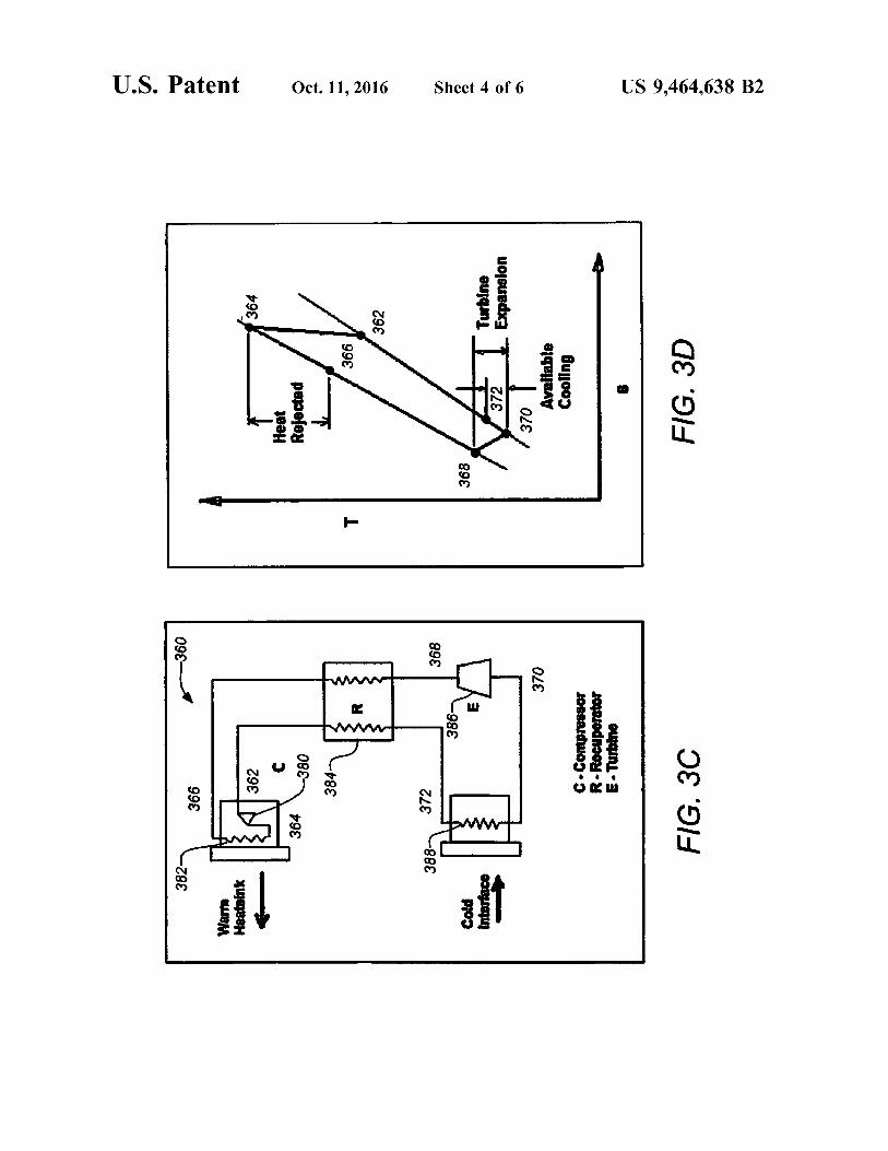
regenerative heat exchanger in the apparatus 360 as shownin FIG. 3C. FIG. 3D. illustrates the closed cycle reverseBrayton process performed by the apparatus 360 of FIG. 3C
40 with the various states of the air indicated by the corre-sponding state labels 362-372. Dry air enters the compressor380 at 362 and through isentropic compression heats to state364, which is run through a heat exchanger 382 (similar toa condenser heat exchanger in a conventional vapor com-
45 pression system). The hot gas cools to state 366 and is sentto the regenerator 384 which cools the gas even further tostate 368. The gas then undergoes isentropic expansionthrough the turbine expander 386 and is cooled to its coldeststate, state 370. The cold gas enters the cold heat exchanger
50 388 and enters state 372 (which cools the automobile cabinair). The still cold gas then enters the regenerator whichabsorbs heat and enters state 362 where the cycle repeats.The benefit of the regenerative closed system is lesser
compressor power to achieve the cooling temperatures andthus improved overall efficiency. Also in all closed systems,
55 because the quality of the air refrigerant is controlled, thelifespan of the system typically increases. The tradeoff withan open system is the need for heat exchangers at the hot andcold side of the cycle. There is an additional associated costfor a regenerator which must be justified versus the gain in
60 performance.
4. Example Method of Cooling Air
FIG. 4 is a flowchart of an exemplary method 400 of65 cooling an automotive cabin. The method 400 comprises a
first operation 402 of receiving engine combustion gases ina first turbine of a bladeless turbocompressor to drive a first

US 9,464,638 B27
bladeless impeller coupled to a second bladeless impeller ofa compressor. In operation 404, air is received and com-pressed in the compressor by the second bladeless impeller.Next in operation 406, the compressed air is received fromthe compressor and cooled with an intercooler. Followingthis in operation 408, the cooled, compressed air is receivedfrom the intercooler and expanded in a second turbine, thesecond turbine having a third bladeless impeller driven bythe cooled, compressed air, the cooled, compressed airexpanding and becoming further cooled thereby.
This method 400 may be altered consistent with thevarious apparatus embodiments previously described toincorporate optional operations. For example, the method400 may further include receiving and heating the air fromthe second turbine by cooling automotive cabin air passedover it in a heat exchanger and then returning the air to thecompressor in a closed cycle and/or generating electricalpower from an alternator coupled to third bladeless impellorof the second turbine. The method 400 may also includereducing moisture content from the air in a drier prior tobeing received by the compressor and/or reducing tempera-ture of the air in a recuperator prior to being received by thecompressor and raising the temperature of the air after beingexpanded by the second turbine. It is also important to notethat the steps may be performed in any suitable order.
5. Baseline Automotive Cabin Air Cooling Sizing& Performance
5
10
15
20
25
30Abaseline example system employing an embodiment of
the invention may be sized based on a typical automobile atthe time of the study (e.g. a 1990 Pontiac Grand Prix), anambient temperature of 52° C. (125° F.), an in-car tempera-ture of 24° C. (75° F.), a vehicle speed of 55 mph and a 35maximum hot soak pull-down time of approximately 120seconds. See Multerer et al., "Alternative Technologies forAutomobile Air Conditioning," Air Conditioning andRefrigeration Center, U. of Illinois, Urbana, 1991, which isincorporated by reference herein. Ambient Conditions and 40Constants are provided in Table I below.
TABLE I
Baseline Air-conditioning and Vehicle Parameters
Parameter Value
Ambient Temperature 52° C.In car temperature 24° C.Solar irradiation 900 W/m2Driving speed 55 mphAir density at 52° C. 1.1 kg/m3Air density at 24° C. 1.3 kg/m3
Thermal conductivity of plate glass 1.4 W/mKWindshield thickness 0.25 inArea of windshield 1.4 mZTotal window area 3.41 mZMax. A/C pull-down time 120 sec
In the example case, the vehicle heat load is dominated bytwo large heat sources: solar irradiation and body conduc-tance. It is a surprising result that when the car is moving,the largest single heat load on the system is not solar, butrather heat conduction/convection through the vehicle win-dows. In other words, in hot weather driving the faster thevehicle travels the more heat convection intrusion dominatesover solar radiation.
Solar radiation is the first major source of heat input to apassenger vehicle and at the surface of the earth is assumed
45
50
8to be 900 W/m2. The total window area of the 1990 PontiacGrand Prix is approximately 3.41 m2, but realizing that halfof the area is exposed to the sun at any given time, themaximum is reduced to 1.7 m2. When a solar view of 30degree is taken into account, this area reduces to 1.5 m2.Glass transmittance is approximately 1.00. With this infor-mation the solar load is calculated as approximately 1.35kW.Though solar radiation heats the vehicle and passenger
compartment during the day whether or not the vehicle isrunning, most air conditioning uses occur when the vehicleis in motion. Next, consider heat that is brought into thevehicle by air convection, then by conduction through thebody panels and windows of the vehicle. For the vehiclevelocities considered, the body conductance roughly varieslinearly with velocity. When traveling at 55 mph, this bodyconductance has a typical value of 80 W/K. When thetemperature difference between the outside and inside of thecar is 28° C. (52-24° C.), the body conductance is approxi-mately 2.24 kW. This is a rough estimate that shows that heatintrusion by conduction into the vehicle roughly varieslinearly with the speed of the vehicle and temperaturedifference with the outside environment. Thus, in thisexample the body load is approximately 60% larger than thesolar load.To sum up the steady-state heat loads affecting the pas-
senger space we must also account for outside air andpassenger heat loads. The most important of these externalloads is the amount of outside air, at ambient temperature,being brought into the passenger compartment. This is avariable load that can be adjusted by the driver of thevehicle. One extreme case involves full inside air recircu-lation with no replacement, while the other extreme replacesthe air about twice a minute. A conservative amount ofreplacement air, 0.25 M3 /min, is assumed for baseline case.The calculation for the replacement air cooling requirementat 0.25 M3 /min and delta T of 28° C. gives 0.12 kW. Thethermal impact of the replacement air is higher for higherflow rates.
In addition, the driver and passenger give off heat,assumed 120 W of heat for a total of 0.24 kW. Finally, asmall amount of heat leaks in from the engine and transaxle,assumed to total approximately 0.50 kW of heat inputinvolves full inside air recirculation with no replacement,while the other extreme replaces the air about twice aminute. A conservative amount of replacement air, 0.25M3 /min, is assumed for the baseline case. The calculation forthe replacement air cooling requirement at 0.25 M3 /min anddelta T of 28° C. gives 0.12 kW. The thermal impact of thereplacement air is higher for higher flow rates. The steady-state heat load summary for the baseline case example isgiven in Table 2 below.
TABLE 255
Total Baseline Heat Load
Parameter Load Fraction
Solar radiative load at 900 W/m2 1.35 kW 0.30Body conductance load at 55 mph 2.24 kW 0.50
60Recirculated air energy 0.12 kW 0.03Driver and one passenger 0.24 kW 0.06Engine loads 0.50 kW 0.11
Total 4.50 kW 1.00
65
A commonly used basis for comparing efficiency of twoA/C systems is the Coefficient of Performance (COP), which

US 9,464,638 B2I
is defined and the energy rate of cooling/input energy.However, the COP index gives unfair advantage to systemsthat use electric power for the input energy and is notsuitably compared with systems that derive input from wasteheat. If waste heat is not used to power the compressor andinstead a belt drive is used to run the compressor, thedifferent identified technologies would compare as shown inFIG. 5A.As shown in FIG. 5A, R134a vapor compression has a
higher COP efficiency than does the "Air Cycle," which isalso known as the belt driven reverse Brayton cycle A/C. Forsystem embodiments of the present invention that deriveinput power from automotive exhaust gas, the COP valuesshould be normalized to meet the following definition: theoverall COP is the heat removed from the vehicle divided bythe heating value of the required fuel.As shown in FIG. 513, the normalization of COP is
accomplished by assuming the base energy efficiency of theautomobile engine is 30%, leaving 70% of the fuel energy asradiator or exhaust waste. For a waste heat-driven A/Csystem, the heat exchanger is assumed to recover 60%,resulting in an overall 42% efficiency. For the belt driven orelectrically-driven systems the drive system is assumed to be90% efficient, which combined with the base engine effi-ciency, results in an overall 27% efficiency. These normal-ized factors are multiplied by the basic COP to give anoverall COP.An ideal reverse Brayton cycle analysis can be performed
to show such a system is capable of removing the necessary4.5 kW vehicle heat load by using the waste heat of theexhaust. Assuming a pressure ratio of 2.25 at the compressorfrom the four states shown previously in Figure XA, theanalysis results in the following temperatures,
Tl = 10° C. hl = 283.15 kJ/kgT2 = 83.5° C. hl = 356.6 kJ/kgT3 = 38° C. h3 = 311.25 kJ/kgT4 = —26.5° C. h4 = 246.64 kJ/kg
Mass flow at the compressor, mdot = 0.1285 kg/s (16.4 lbm/min) and Heat lift, qL, _ (hl— h4) x mdot = 36.51 x 0.1258 = 4.69 kW.
As previously described, the simplicity of a bladelessturbine (i.e. Tesla-type turbine) can allow a low cost, reliabledesign for a turbocompressor and turbine expander that canbe an attractive option for reverse Brayton air conditioningsystems if an efficient design can be achieved. Thoughstandard off the shelf turbocompressors (bladed turbocharg-ers or superchargers) can be designed into a reverse Braytonsystem, it is believed that the cost of the turbocompressorswould make it unattractive compared to a standard vaporcompression system. See V. Carey, "Assessment of TeslaTurbine Performance for Small Scale Rankine CombinedHeat and Power Systems," J. of Engineering for Gas Tur-bines and Power, ASME, December 2010, Vol. 132, whichis incorporated by reference herein.A study performed by Beatrice and Fiorelli demonstrated
that the use of off an existing commercial off the shelf(COTS) turbocompressor from Honeywell/Garrett wouldresult in a system that is approximately 40% more expensivethan a standard vapor compression system. Main compo-nents for a conventional freon R134a vapor compressionsystem are estimated as compressor ($800), evaporator/expansion device ($500), and condenser ($400), totaling$1,700. In contrast, a reverse Brayton cycle system employ-ing a COTS turbocompressor includes main componentsestimated as turbocompressor ($2,000), intercooler ($300),evaporative system/dryer ($200), and expansion device
10($150), totaling $2,650. See Beatrice et al., "Feasibility of aBrayton Cycle Automotive Air Conditioning System,"Engenharia Termica, Vol. 8, No. 2, December 2009, whichis incorporated by reference herein.
5 Embodiments of the present invention which employreverse Brayton A/C system driven by waste heat can deliveran overall COP of 0.63 comparable to existing R134a vaporcompression of 0.68. It is further estimated that use of thebladeless turbine technology at the compressor and expander
io will increase the COP and even surpass that of vaporcompression. In addition, it is estimated that the significantlylower cost of bladeless turbines over COTS turbocompres-sors will enable system cost to be at least comparable tostandard vapor compression systems.
15 It is estimated that on average a midsize vehicle willconsume about one gallon of gasoline for every one hourthat it idles. Under these conditions and assuming a gallonof gasoline contains 39 kW of energy rate content. Consid-ering experimental data provided by manufacturers, the
20 turbocompressor increases the outlet engine pressure by3.5% in the worst case scenario, and the impact on theengine power is nearly the same. So if the engine power atidle is 39 kW, the turbocompressor impact is 1.35 kW, whichis enough power to provide a decent amount of air condi-
25 tioning and in the neighborhood of the input power requiredfor a conventional air conditioning system.By using off the shelf components, Beatrice and Fiorelli
had their system evaluated at 11.5 kg, while a conventionalvapor compression system weighed 10.5 kg. The turbocom-
30 pressor accounts for over 50% of the total weight, similar toa conventional vapor compression system, and most of theweight is due to a very thick and heavy housing needed tomeet safety standards from high speed rotation. A bladelessTesla turbine would not require as thick of housing because
35 of the lower rotation inertia compared to centrifugal blades.It is estimated that the total weight of a system with abladeless Tesla turbine should drop below 10 kg.As seen from the performance estimates of the system, the
air will cool well below dew point and the moisture will4o have to be removed before being sent to the vehicle cabin.
Off the shelf air driers/descicants exist that can be put intothe system; they are conch shaped and remove dew from theair by rotating it and having it condense on the walls.In the event that the air is not cooled substantially cooled
45 below dew point, a recuperator can be placed between airintake of the compressor and air exit into the vehicle cabinas shown in the apparatus 300 referring back to FIG. 3A.Recuperators and driers are known in the art and anysuitably size device may be employed as will be understood
5o by those skilled in the art. The recuperator can be a plate-type air-to-air heat exchanger, that are both low cost andhigh efficiency. The recuperator 328 lowers the temperatureof the ambient air as before it enters the compressor 308,which allows for higher compressibility as colder air com-
55 presses more efficiently. It also lowers to overall temperatureof the incoming air. Condensate can be collected andremoved (reducing moisture content) from the ambient airby a drier 330 before entering the compressor 308 disposedbetween the recuperator 328 and the compressor 308. As the
6o air leaves the turbine 318 and enters the recuperator 328, itthen heats the air a little (which still remains cool) butmaking it more comfortable for the passengers. Another,relatively simple approach for drying could be implementedusing membranes to dehumidify the air before it enters the
65 Brayton turbocompressor. The drier used in aircraft is aspin/centrifugal type that separates moisture from the air byrotation and can be employed in the automotive application.

US 9,464,638 B211
The drier can also be a plate-type adsorption drier thatallows condensation to happen on the plate surface.
This concludes the description including the preferredembodiments of the present invention. The foregoingdescription including the preferred embodiment of theinvention has been presented for the purposes of illustrationand description. It is not intended to be exhaustive or to limitthe invention to the precise forms disclosed. Many modifi-cations and variations are possible within the scope of theforegoing teachings. Additional variations of the presentinvention may be devised without departing from the inven-tive concept as set forth in the following claims.What is claimed is:1. An apparatus for cooling an automotive cabin, com-
prising:a bladeless turbocompressor including a first turbine
receiving engine combustion gases which drive a firstbladeless impeller coupled to a second bladeless impel-ler of a compressor, the compressor receiving air whichis then compressed by the second bladeless impeller;
an intercooler coupled to receive and cool the compressedair from the compressor; and
a second turbine receiving the cooled, compressed airfrom the intercooler, the second turbine having a thirdbladeless impeller uncoupled from the first bladelessimpeller and the second bladeless impeller and drivenby the cooled, compressed air, the cooled, compressedair expanding and becoming further cooled thereby.
2. The apparatus of claim 1, wherein each of the first,second and third bladeless impellers comprises a plurality ofplanar discs spaced apart in a stack on a common shafthaving fluid passages cut therethrough near the central shaft.
3. The apparatus of claim 2, wherein spacing between theplurality of planar discs enables laminar fluid flow of the airto develop beginning at a boundary layer between the air andplanar surfaces of the planar discs.
4. The apparatus of claim 2, wherein spacing between theplurality of planar discs is such that choked flow does notoccur.
5. The apparatus of claim 1, wherein the first bladelessimpeller is coupled to a second bladeless impeller by acommon shaft.
6. The apparatus of claim 1, wherein the air received bythe compressor is ram air directed in from outside thevehicle.
7. The apparatus of claim 1, further comprising a heatexchanger receiving the air from the second turbine andheating it by cooling automotive cabin air passed over it, theheat exchanger then returning the air to the compressor in aclosed cycle.
8. The apparatus of claim 1, further comprising an alter-nator coupled to third bladeless impellor of the secondturbine for generating electrical power.
9. The apparatus of claim 1, further comprising a drier forreducing moisture content from the air prior to beingreceived by the compressor.
10. The apparatus of claim 9, further comprising a recu-perator for reducing temperature of the air prior to beingreceived by the compressor and raising the temperature ofthe air after being expanded by the second turbine.
11. A method for cooling an automotive cabin, compris-ing:
12receiving engine combustion gases in a first turbine of a
bladeless turbocompressor to drive a first bladelessimpeller coupled to a second bladeless impeller of acompressor;
5 receiving and compressing air in the compressor by thesecond bladeless impeller;
receiving and cooling the compressed air from the com-pressor with an intercooler; and
receiving and expanding the cooled, compressed air from10 the intercooler in a second turbine, the second turbine
having a third bladeless impeller uncoupled from thefirst bladeless impeller and the second bladeless impel-ler and driven by the cooled, compressed air, the
15 cooled, compressed air expanding and becoming fur-ther cooled thereby.
12. The method of claim 11, wherein each of the first,second and third bladeless impellers comprises a plurality ofplanar discs spaced apart in a stack on a common shaft
20 having fluid passages cut therethrough near the central shaft.13. The method of claim 12, wherein spacing between the
plurality of planar discs enables laminar fluid flow of the airto develop beginning at a boundary layer between the air andplanar surfaces of the planar discs.
25 14. The method of claim 12, wherein spacing between the
plurality of planar discs is such that choked flow does notoccur.15. The method of claim 11, wherein the first bladeless
impeller is coupled to a second bladeless impeller by a
30 common shaft.
16. The method of claim 11, wherein the air received bythe compressor is ram air directed in from outside thevehicle.17. The method of claim 11, further comprising receiving
35 and heating the air from the second turbine by coolingautomotive cabin air passed over it in a heat exchanger andthen returning the air to the compressor in a closed cycle.
18. The method of claim 11, further comprising generat-ing electrical power from an alternator coupled to third
40 bladeless impellor of the second turbine.
19. The method of claim 11, further comprising reducingmoisture content from the air in a drier prior to beingreceived by the compressor.
20. The method of claim 19, further comprising reducing45 temperature of the air in a recuperator prior to being received
by the compressor and raising the temperature of the air afterbeing expanded by the second turbine.
21. An apparatus for cooling an automotive cabin, com-prising:
50 a first bladeless means for driving a second bladelessmeans from received engine combustion gases, thesecond bladeless means for compressing received airdriven by the first bladeless means;
a cooling means for cooling the compressed air from the
55 compressor; and
a third bladeless means for expanding the receivedcooled, compressed air from the cooling means, thethird bladeless means uncoupled from the first blade-less means and the second bladeless means and driven
60 by the cooled, compressed air, the cooled, compressedair expanding and becoming further cooled thereby.