(12) united states patent (10) patent no.: us 8,261,256 b1 · 314 audio - interface 312 sdram -b-...
TRANSCRIPT

USOO826 1256B1
(12) United States Patent (10) Patent No.: US 8,261,256 B1 Adler et al. (45) Date of Patent: Sep. 4, 2012
(54) SYSTEMAND METHOD FOR (51) Int. Cl. AUTOMATICALLY UPDATING THE G06F 9/445 (2006.01) SOFTWARE OF ANETWORKED PERSONAL (52) U.S. Cl. ........................................ 717/173; 717/178 AUDIOVISUAL DEVICE (58) Field of Classification Search ........................ None
(75) Inventors: Steven M. Adler, San Diego, CA (US); Joseph B. Grand, San Diego, CA (US); Andrew S. Huang, Cardiff-by-the-Sea, CA (US): Duane S. Maxwell, San Diego, CA (US); Kenneth E. Steele, San Diego, CA (US); Stephen L. Tomlin, San Diego, CA (US)
(73) Assignee: BBY Solutions, Inc., Richfield, MN (US)
(*) Notice: Subject to any disclaimer, the term of this patent is extended or adjusted under 35 U.S.C. 154(b) by 1316 days.
(21) Appl. No.: 11/845,027
(22) Filed: Aug. 24, 2007
Related U.S. Application Data (60) Provisional application No. 60/805,830, filed on Sep.
5, 2006, provisional application No. 60/823,491, filed on Aug. 24, 2006, provisional application No. 607823,493, filed on Aug. 24, 2006, provisional application No. 60/823,496, filed on Aug. 24, 2006, provisional application No. 60/945,900, filed on Jun. 22, 2007, provisional application No. 60/869,297, filed on Dec. 8, 2006.
320
TOUCHSCREN SpAY
LCD COMTROLLER
322
330 OUCHSCREEN CONTROLLER
334
CPU
See application file for complete search history.
(56) References Cited
U.S. PATENT DOCUMENTS
7,181,731 B2 * 2/2007 Pace et al. ..................... 717/136 2004/0098.715 A1* 5/2004 Aghera et al. ... 717, 173 2008/0010372 A1 1/2008 Khedouri et al. ............. TO9,224
* cited by examiner
Primary Examiner — Chuck Kendall (74) Attorney, Agent, or Firm — Schwegman Lundberg & Woessner, P.A.
(57) ABSTRACT
A method for automatically updating software executed by an electronic device is disclosed herein. The method includes receiving, at the electronic device, an update indication from a server that updated software is available for the electronic device. The method further includes modifying, in response to the update indication, a boot state of the electronic device and initiating operation of the electronic device in an update mode. The updated software is received, at the electronic device, during operation in the update mode. The method further includes initiating, upon determining the updated software has been correctly received, operation of the elec tronic device in a normal mode.
15 Claims, 61 Drawing Sheets
W-Fi COMMUNICATIONS NRAC
314 AUDIO - INTERFACE
312
SDRAM -b-
306
WIDGETS 350
3 O 2 le
He
WDGET-PARAMETERS SENSOR 352
INTERFACE 370 FLASHPAYER
360
OPERATING SYSTEM 364
NON-WOLATILE MEMORY
10
US 8,261,256 B1 Sheet 2 of 61 Sep. 4, 2012 U.S. Patent

US 8,261,256 B1 Sheet 3 of 61 Sep. 4, 2012 U.S. Patent
El OV-HRHE_LNI
>]OSNESNEE, JOSHO (YOL099

US 8,261,256 B1 Sheet 4 of 61 Sep. 4, 2012
007
U.S. Patent

U.S. Patent Sep. 4, 2012 Sheet 5 of 61 US 8,261,256 B1
502
512
U.S. Patent Sep. 4, 2012 Sheet 6 of 61 US 8,261,256 B1
FIG.SB

U.S. Patent Sep. 4, 2012 Sheet 7 of 61 US 8,261,256 B1
... --- - - - - - - -es a rear is a a
508
FIG.SC

U.S. Patent Sep. 4, 2012 Sheet 8 of 61 US 8,261,256 B1
502

O
US 8,261,256 B1
502
Sheet 9 of 61 Sep. 4, 2012 U.S. Patent
|
FG, SE
U.S. Patent Sep. 4, 2012 Sheet 10 of 61 US 8,261,256 B1
(GETHE ESSEESE E.
N7 1 FT ITN N
| | 9 C
i U < \e ve 9 2
s
U.S. Patent Sep. 4, 2012 Sheet 11 of 61

U.S. Patent Sep. 4, 2012 Sheet 12 of 61 US 8,261,256 B1
FIG. 6F
U.S. Patent Sep. 4, 2012 Sheet 13 of 61 US 8,261,256 B1
512
US 8,261,256 B1 Sheet 14 of 61 Sep. 4, 2012 U.S. Patent

US 8,261,256 B1 Sheet 15 of 61 Sep. 4, 2012 U.S. Patent

U.S. Patent
Request Chumby Configuration
902
Process Chumby Configuration
91
POCeSS Error
Sep. 4, 2012
Configuration module - includes Chumby GUID
Configuration
Respond w/XMLERROR
FIG. 9
Sheet 16 of 61
- - - - - - - - - - - - - - - - -
US 8,261,256 B1
900
SERVICE PROVIDER 106
Receive
Retrieve Chumby Config. from DB
908

U.S. Patent Sep. 4, 2012 Sheet 17 of 61 US 8,261,256 B1
1000
- - - - - - - - - - - - - - - - -
CHUMBYTM DEVICE
HTTP GET to profile module: RECEIVE REOUEST
1004
REOUEST PROFILE
1002
- includes profile GUID
RETRIEVE PROFILE FROM DATABASE
1008
Respond wiXML profile PROFILE EXISTS?
1012
PROCESS PROFILE
1016
PROCESS Respond w/XMLERROR
FIG. 10

U.S. Patent Sep. 4, 2012 Sheet 18 of 61 US 8,261,256 B1
11OO
CHUMBYTM DEVICE SERVICE PROVIDER
HTTP POST to PARAMS module SEND WIDGET
NSTANCE CHANGE 4XML widget instance data RECEIVE CHANGE REQUEST
REO UEST 1102 1104.
WRITE WIDGE INSTANCE TO DATABASE
110
Respond wiXMLERROR PROCESS ERROR
RETRIEVE WIDGET INSTANCE FROM
DATABASE 1116
PROCESS WDGET Respond wiXML PARAMS NSTANCE
SEND UPDATED WDGET INSTANCE
1120
FIG. 11
U.S. Patent
INSTANCE
INSTANCE
CHUMBYTM DEVICE
REGUEST WIDGET
DOWNLOAD 1202
PROCESS WIDGET
Sep. 4, 2012 Sheet 19 of 61 US 8,261,256 B1
SERVICE PROVIDER
HTTP GET to PARAMS module:
includes widget instance GUID RECEIVE REOUEST
1204
RETRIEVE WOGET INSTANCE FROM
DATABASE 1208
WIDGET INSTANCE EXISTS?
Respond wiXML widget instance
1212 1220
U.S. Patent Sep. 4, 2012 Sheet 20 of 61 US 8,261,256 B1
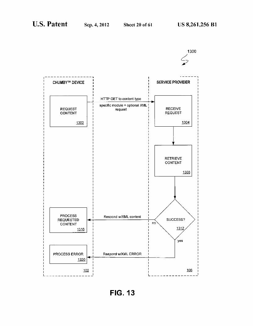
1300
SERVICE PROVIDER
HTTP GET to content-type specific module+ optional XML
RECUEST request CONTENT
RECEIVE REQUEST
1302 1304
RETRIEVE CONTENT
1308
PROCESS Respond wiXML content RECUESTED CONTENT
1316
PROCESS ERROR Respond wiXML ERROR 1320
FIG. 13
US 8,261,256 B1 Sheet 21 of 61 Sep. 4, 2012 U.S. Patent
U.S. Patent Sep. 4, 2012 Sheet 22 of 61 US 8,261,256 B1
w ver
y
s
d o
v
S

U.S. Patent Sep. 4, 2012 Sheet 23 of 61 US 8,261,256 B1
Touchscreen
FIG. 16B
Touchscreen e Drag the ba fing Ato B with yourfinger, If
o Stopping E. along the way is OK • Worked fine? Press poNE. If nitress RETRY or wait 15 secgids to try again.B.
1607
FIG. 16
US 8,261,256 B1 Sheet 25 of 61 Sep. 4, 2012 U.S. Patent

US 8,261,256 B1 Sheet 26 of 61 Sep. 4, 2012 U.S. Patent

US 8,261,256 B1 Sheet 27 of 61 Sep. 4, 2012 U.S. Patent
OZOZ
US 8,261,256 B1 Sheet 28 of 61 Sep. 4, 2012 U.S. Patent
Z 1. || Z.

US 8,261,256 B1 Sheet 29 of 61 Sep. 4, 2012 U.S. Patent
OZZZ :
00ZZ
96ed euJOH

US 8,261,256 B1 Sheet 30 of 61 Sep. 4, 2012 U.S. Patent
0092
US 8,261,256 B1 Sheet 31 of 61 Sep. 4, 2012 U.S. Patent
007Z
ON ON
O N
ON
US 8,261,256 B1 Sheet 32 of 61 Sep. 4, 2012 U.S. Patent
GZ "SOIH OGGZ
?æ6pINA BAeS,

U.S. Patent Sep. 4, 2012 Sheet 33 of 61 US 8,261,256 B1
26OO
is Choose Option & GO: w GO Edit FIG. 26A Widget
Remove BACK Widget If
Choose Category & GO:
A GO
FIG. 26B V
Choose Widget & GO:
Widget 1 A GO Widget 2 r|. FIG. 26C
Widget N V back
You have selected the “Name' widget:
“Widget description.” F G 26 D Continue?
Go
onfigure Widget Now?
Go FIG. 26E OR
Use Defaults for Widget.

U.S. Patent Sep. 4, 2012
Downloading Widget
REQUEST WIDGET DESCRIPTION
CHUMBYTM DEVICE
PROCESS WIDGET DESCRIPTION
2716
REGUEST WIDGET
2720
EXECUTE MOVIE
2736
PROCESS ERROR
HTTP GET to Widget Description Module
- includes GUID of widget
Respond WXML Widget Desc.
HTTP GET to "movie" module
Sheet 34 of 61
27OO
SERVICE PROVIDER
RECEIVE REQUEST
2704
RETRIEVE WIDGET DESC. FROM DB
2708
v
u1 N. WDGE DESC.
EXISTS?
Respond wiXML movie.swf
Respond wiXML Error
Respond wiXML Error
FIG. 27
RETRIEVE MOVE
2728
MOVIE EXISTS? yes 1.
US 8,261,256 B1
U.S. Patent Sep. 4, 2012 Sheet 35 of 61 US 8,261,256 B1
502
512
U.S. Patent Sep. 4, 2012 Sheet 36 of 61 US 8,261,256 B1
508
2904
FIG. 29

US 8,261,256 B1 U.S. Patent

U.S. Patent Sep. 4, 2012 Sheet 39 of 61 US 8,261,256 B1
3210
NAUTS CANNs Stuff On MV Mus. De ..". D (g)
NGHT WMUSIC
(O (3) ee TING CAOCK -
RATs belETs
() ()() () Got controlone)
N 2.17
FIG. 32
U.S. Patent Sep. 4, 2012 Sheet 40 of 61 US 8,261,256 B1
3300
Squeeze When you sque our Chuimby, the blue bar Will move. E. E. to somewhere between the positions of the blue bar when Squeezed and unsqueezed.
N SQUEEZE THRESHOLD x
C 727 - A -
FIG. 33

US 8,261,256 B1 Sheet 41 of 61 Sep. 4, 2012 U.S. Patent
0079
aff

US 8,261,256 B1 Sheet 42 of 61 Sep. 4, 2012 U.S. Patent
Z099
?senbau

US 8,261,256 B1 Sheet 43 of 61 Sep. 4, 2012 U.S. Patent
\/99, "SOI
£199 "SDI
US 8,261,256 B1 U.S. Patent
US 8,261,256 B1 Sheet 45 of 61 Sep. 4, 2012 U.S. Patent
099 "SDIE

US 8,261,256 B1 Sheet 46 of 61 Sep. 4, 2012
+ = - - ----+-----------+- - - - -+------+----- == -------+-----------------+
U.S. Patent
US 8,261,256 B1 Sheet 48 of 61 Sep. 4, 2012 U.S. Patent
H99 "SDIE
xse
US 8,261,256 B1 Sheet 49 of 61 Sep. 4, 2012 U.S. Patent
prooea eraour worz?ean 6 Ezuoo eq?
aer eqq Egº circae
H99 "SDI
US 8,261,256 B1 U.S. Patent
US 8,261,256 B1 Sheet 52 of 61 Sep. 4, 2012
(~~~
0099
U.S. Patent
U.S. Patent Sep. 4, 2012 Sheet 53 of 61 US 8,261,256 B1
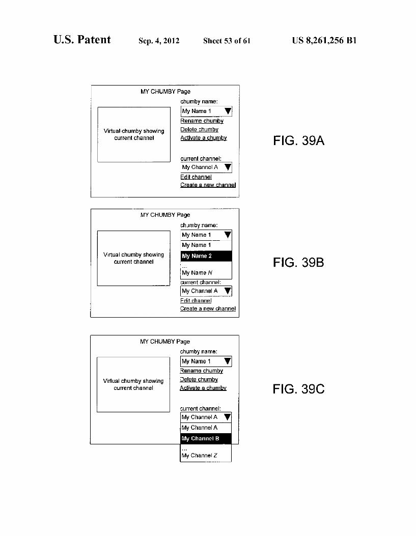
MY CHUMBY Page chumby name: My Name 1 V Rename chumby
Virtual chumby showing Delete Chumb Current Channel Activate a Chunb F G 39 A
Current channel:
My Channel A V Edit channel Create a new channel
MY CHUMBY Page chumby name: My Name 1 V My Name 1
Virtual Chumby showing Current channel
My Name 2
My Name N Current channel:
My Channel A V Edit Channel
FG. 39B
Create a new channel
MY CHUMBY Page chumby name: My Name 1 V Rename chunby
Virtual chumby showing Delete churmby Current channel Activate a chumby FIG. 39C
Current channel:
My Channel A V My Channel A My Channel B
My Channel Z
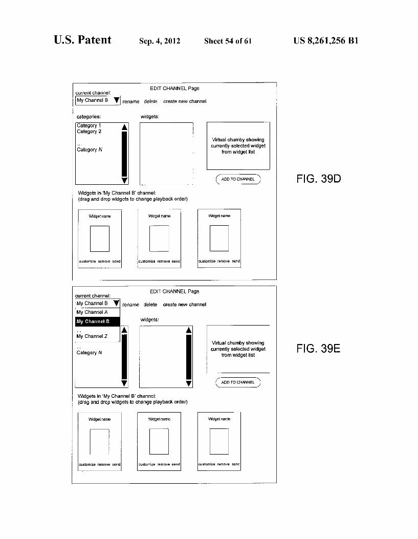
U.S. Patent Sep. 4, 2012 Sheet 54 of 61
EDITCHANNEL Page current channel:
My Channel B V rename delete create new channe
categories: widgets: Category 1 Category 2 A
Category N
Widgets in "My Channel B' channel: (drag and drop widgets to change playback order)
Virtual chumby showing currently selected widget
from widget list
ADD TO CHANNEL
Widgetname Widget name Widgetname
customize remove send customize remove send Customize remove send
EDIT CHANNEL Page Current channel:
My Channel B V rename delete create new channel My Channel A My Channel B widgets:
My Channel Z.
Category N
V V
Widgets in "My Channel B' channel: (drag and drop widgets to change playback order)
Widgetname Widget name
customize remove send customize remove send customize remove send
Virtual chumby showing Currently selected widget
from widget list
ADD TO CHANNEL
Widgetname
US 8,261,256 B1
FIG. 39D
FIG. 39E
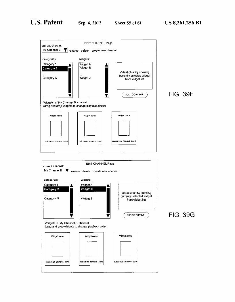
U.S. Patent Sep. 4, 2012 Sheet 55 of 61
EDITCHANNEL Page Current channel: My Channel B v rename delete Create new channel
categories: widgets: Category 1 A Widget A A
Widget B Virtual chumby showing currently selected widget
Category N Widget Z from widget list
V V
Widgets in 'My Channel B' channel: (drag and drop widgets to change playback Order)
Widget name Widget name
customize ?emove Send customize remove send customize remove send
EDITCHANNELPage current Channel:
My Channel B V rename delete create new channel
categories: widgets: Category 1 A WidgetA A Category 2
Virtual chumby showing Currently selected widget
Category N from widget list
V
Widgets in "My Channel B' channel: (drag and drop widgets to change playback Order)
Widget name Widgetname Widget name
customize remove send customize remove send customize remove send
US 8,261,256 B1
FIG. 39F
FIG. 39G

U.S. Patent Sep. 4, 2012 Sheet 56 of 61 US 8,261,256 B1
EDITCHANNEL Page Current Channel.
My Channel B V rename delete create new channel
categories: widrats:
Category 1 Category 2
Widget Name
Play widget For 30 Seconds V irtual churnby showing rrently selected widget
Category N from widget list
Field A. Walue A
Field B: Walue B
Field C: Value C Widgets in "My Ch ---
FIG. 39H (drag and drop wi Option P
Option Q Widget name
Option R X
customize remove send customize remove send customize remove send

U.S. Patent Sep. 4, 2012 Sheet 57 of 61 US 8,261,256 B1
Default
FIG. 40B
US 8,261,256 B1 Sheet 58 of 61 Sep. 4, 2012 U.S. Patent
ON
ON
ON

U.S. Patent Sep. 4, 2012 Sheet 59 of 61 US 8,261,256 B1
4200A
From FG 42B From FIG 42C Stage 4258 BL initialized Stage 4214
GO TO FIG 42C Stage 4260
GO TO FIG 42B Stage 4226 Check SEMAPHORE
On MSP
4222
FIG. 42A
U.S. Patent Sep. 4, 2012 Sheet 60 of 61 US 8,261,256 B1
42OOB
From FG AUTO. UPDATE 5's
MODE SE 4222 load/execute K2
4226 User Oliphate
Reboots? successful
MOUNTRFS2 4230
fall back to eat
atternatibe transport client
Redundant HTTP transfer succeeded?
Load WIFI config from PSP, Connect to
SPECIAL OPTIONS mode
1fall back to HTTP altell attle 4238
transfer transport client succeeded?
estart to NORMAL
OPERATION heck update
available flag on PSP - Update
needed?
YES
Download torrent file via HTTP
Bit Torrent
Succeeded
Execute Bit Torrent client and preallocate image space on NAND.
Validate checksum 4244 for a chunks.
Extract downloaded image and write partition image(s) to NAND
Clear SEMAPHORE
on MSP
GO TO FIG 42A Stage
4218
FIG. 42B

U.S. Patent Sep. 4, 2012 Sheet 61 of 61 US 8,261,256 B1
SEMAPHORE on MSP for
MODE Load/execute
User Aphate Reboots? secessful MOUNTRFS1 Load
WIFI config from PSP.
4281 Connect to
Go To FG 42A Stage Check
edunda fall back to PSP - Update 4218 http rebuilitat needed? transfer alternate
Set SEMAPHOR E On M
dfall back to Download torrent alternatibe file via HTTP
transport client transfer
YES Torrent client and preallocate image space on NAND Walidate checksum for a Set update
available flag on PSP
4211
Succeede
Clear SEMAPHOR E on MSP
Continue NORMAL
OPERATION
Extract downloaded
image and write partition image(s)
UNAVAILABLE
User Desires to Update?
m for firmware
4204 4206
FIG. 42C

US 8,261,256 B1 1.
SYSTEMAND METHOD FOR AUTOMATICALLY UPDATING THE
SOFTWARE OF ANETWORKED PERSONAL AUDIOVISUAL DEVICE
CROSS-REFERENCE TO RELATED APPLICATIONS
This application claims priority under 35 U.S.C. S 119(e) to U.S. Provisional Application Ser. No. 60/805,830 filed Sep. 5, 2006, entitled CONFIGURABLE PERSONAL AUDIOVI SUAL DEVICE FOR USE IN NETWORKED APPLICA TION SHARING SYSTEM, to U.S. Provisional Application Ser. No. 60/823,491 filed Aug. 24, 2006, entitled SYSTEM AND METHOD FOR TRANSFERRING ELECTRONIC CONTENT TO NETWORKED PERSONAL AUDIOVI SUAL DEVICES, to U.S. Provisional Application Ser. No. 60/823,493 filed Aug. 24, 2006, entitled NETWORKED PERSONAL AUDIOVISUAL DEVICE HAVING FLEX IBLE HOUSING, to U.S. Provisional Application Ser. No. 607823,496 filed Aug. 24, 2006, entitled SYSTEM AND METHOD FOR AUTOMATICALLY UPDATING THE SOFTWARE OF ANETWORKED PERSONAL AUDIOVI SUAL DEVICE, to U.S. Provisional Application Ser. No. 60/945,900 filed Jun. 22, 2007, entitled REGISTRATION SYSTEMS AND METHODS FOR PERSONALIZED POR TABLE DEVICES, and to U.S. Provisional Application Ser. No. 60/869,297 filed Dec. 8, 2006, entitled SYSTEMAND METHODS FOR LOCATION, MOTION, AND CONTACT DETECTION AND TRACKING IN A NETWORKED AUDIOVISUAL DEVICE, each of which is incorporated herein by reference in its entirety. This application is related to U.S. patent application Ser. No. 1 1/845,018, entitled CON FIGURABLE PERSONAL AUDIOVISUAL DEVICE FOR USE IN NETWORKED APPLICATION SHARING SYS TEM, filed on even date herewith, to U.S. patent application Ser. No. 1 1/845,026, entitled SYSTEM AND METHOD FOR TRANSFERRING ELECTRONIC CONTENT TO NETWORKED PERSONAL AUDIOVISUAL DEVICES, filed on even date herewith, and to U.S. patent application Ser. No. 1 1/845,021, entitled NETWORKED PERSONAL AUDIOVISUAL DEVICE HAVING FLEXIBLE HOUS ING, filed on even date herewith, all of which are incorpo rated by reference in their entirety.
BACKGROUND OF THE INVENTION
It is well known that broadband Internet connectivity is becoming Substantially more pervasive among consumers as a result of competition among service providers utilizing various different technologies (e.g., cable, digital Subscriber line (DSL), satellite). In many households personal comput ers (PCs) constitute the primary users of the bandwidth fur nished by these broadband connections. In order to facilitate sharing of the Internet connection among PCs in a given household, a variety of “wired and “wireless' home net working technologies have been utilized. As a result of the impracticality of installing Ethernet cable
throughout a residence, RF-based wireless networking tech nology is becoming increasingly commonplace among con Sumers. Although systems based upon the 802.11b, or “Wi Fi”, wireless networking standard may currently be the most pervasive, versions of the 802.11 standard offering increased bandwidth have been introduced and yet higher-bandwidth approaches have been proposed. The increased bandwidth available within the home has
increased the usage of a number of different services, such as
10
15
25
30
35
40
45
50
55
60
65
2 Internet-based delivery of digital audio, video and graphic content. However, since many of these services are facilitated by a desktop or notebook PC capable of communication over a broadband Internet connection, users are forced to remain proximate to their respective computers in order to utilize Such services. Although other strategies to leverage the avail ability of broadband Internet connectivity within the home are currently being developed, many of these approaches involve creation of a relatively powerful, costly centralized communications “hub” (e.g., a PC with enhanced media capabilities, or a multi-purpose cable set-top box). Unfortu nately, this typically requires either the purchase of an expen sive hardware device or extended Subscription plan, and con strains the extent to which Internet-enabled entertainment or other services are enjoyed outside of the immediate vicinity of the centralized hub device.
Accordingly, the increasing availability of wireless band width within the home and elsewhere creates an opportunity for economically leveraging this bandwidth in a flexible, consumer-friendly manner.
SUMMARY OF THE INVENTION
In Summary, one aspect of the present invention relates to a method for automatically updating software executed by an electronic device. The method includes receiving, at the elec tronic device, an update indication from a server that updated software is available for the electronic device. The method further includes modifying, in response to the update indica tion, a boot state of the electronic device and initiating opera tion of the electronic device in an update mode. The updated Software is received, at the electronic device, during operation in the update mode. The method further includes initiating, upon determining the updated Software has been correctly received, operation of the electronic device in a normal mode.
In another aspect the present invention relates to a machine-readable medium having instructions stored thereon for execution by a processor to perform a method. The method includes receiving, at the electronic device, an update indication from a server that updated software is available for the electronic device. The method further includes modify ing, in response to the update indication, a boot state of the electronic device. Following initiation of operation of the electronic device in an update mode, the updated Software is received at the electronic device. The method includes initi ating, upon determining the updated Software has been cor rectly received, operation of the electronic device in a normal mode.
Yet another aspect of the invention relates to a method which involves initially operating an electronic device in a normal mode. The method includes rebooting the electronic device into an update mode following unintended termination of the operation of the electronic device in the normal mode. The method further includes receiving, during operation of the electronic device in the update mode, updated software for the electronic device.
BRIEF DESCRIPTION OF THE DRAWINGS
For a better understanding of the nature of the features of the invention, reference should be made to the following detailed description taken in conjunction with the accompa nying drawings, in which:
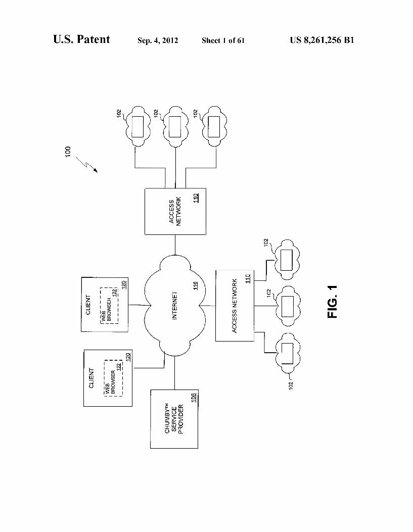
FIG. 1 is a block diagram illustrating a set of networked components comprising an exemplary embodiment of the system of the invention.
US 8,261,256 B1 3
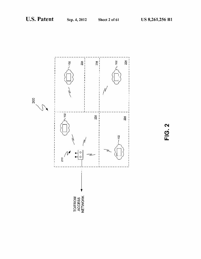
FIG. 2 illustrates an exemplary distribution of CHUMBYTM devices throughout a residence or other build ing having a number of rooms.
FIG.3 provides a block diagrammatic representation of the principal components of an embodiment of a CHUMBYTM device of the present invention.
FIG. 4 shows an exemplary user interface generated through a screen of a CHUMBYTM device during operation of the CHUMBYTM device in a control panel mode.
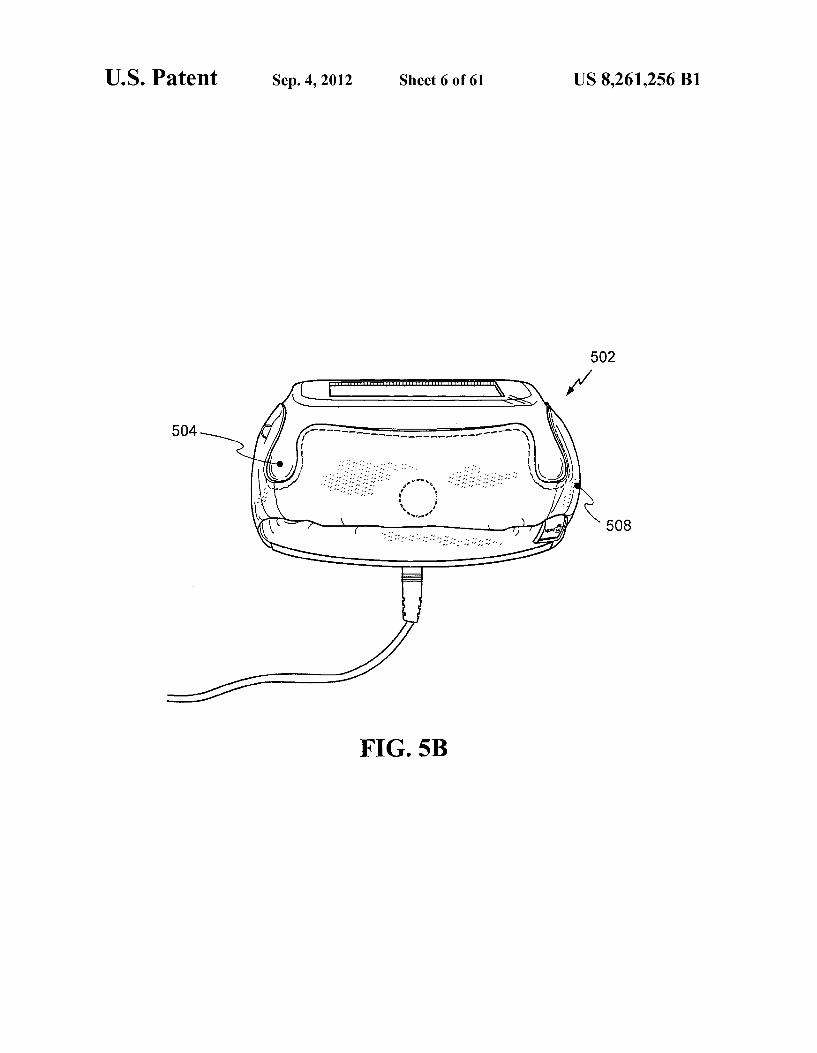
FIGS. 5A-5E provides various perspective views of an exemplary CHUMBYTM device configured with a malleable housing.
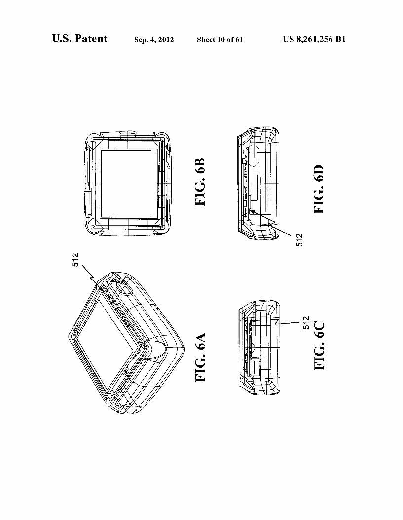
FIGS. 6A-6D provide various partially transparent per spective, side and plan views of an embodiment of the CHUMBYTM device.
FIGS. 6E-6G depict the core electronics and other compo nents contained within the housing of a CHUMBYTM device and the arrangement of certain of these components within a housing of the device.
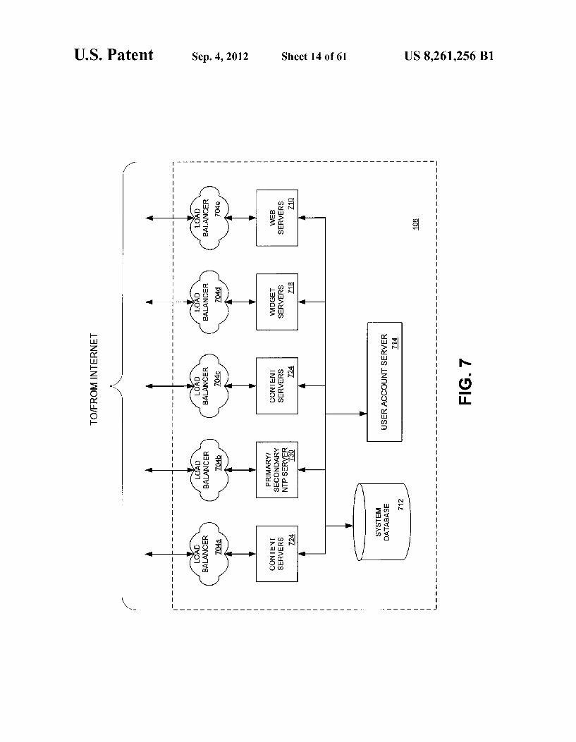
FIG.7 provides a block diagrammatic representation of the server components and other infrastructure which may be utilized to facilitate the operations of a CHUMBYTM service provider.
FIG. 8 provides a database model diagram of an exemplary object-oriented database schema utilized by a system data base.
FIG. 9 is a signal flow diagram representative of one man ner in which a configuration is provided to a CHUMBYTM device by a service provider.
FIG. 10 is a signal flow diagram which represents one manner in which a profile is provided to a CHUMBYTM device by a service provider.
FIG. 11 is a signal flow diagram which depicts processing of changes made to the parameters of a widget instance through the interface of a CHUMBYTM device in which the widget is instantiated.
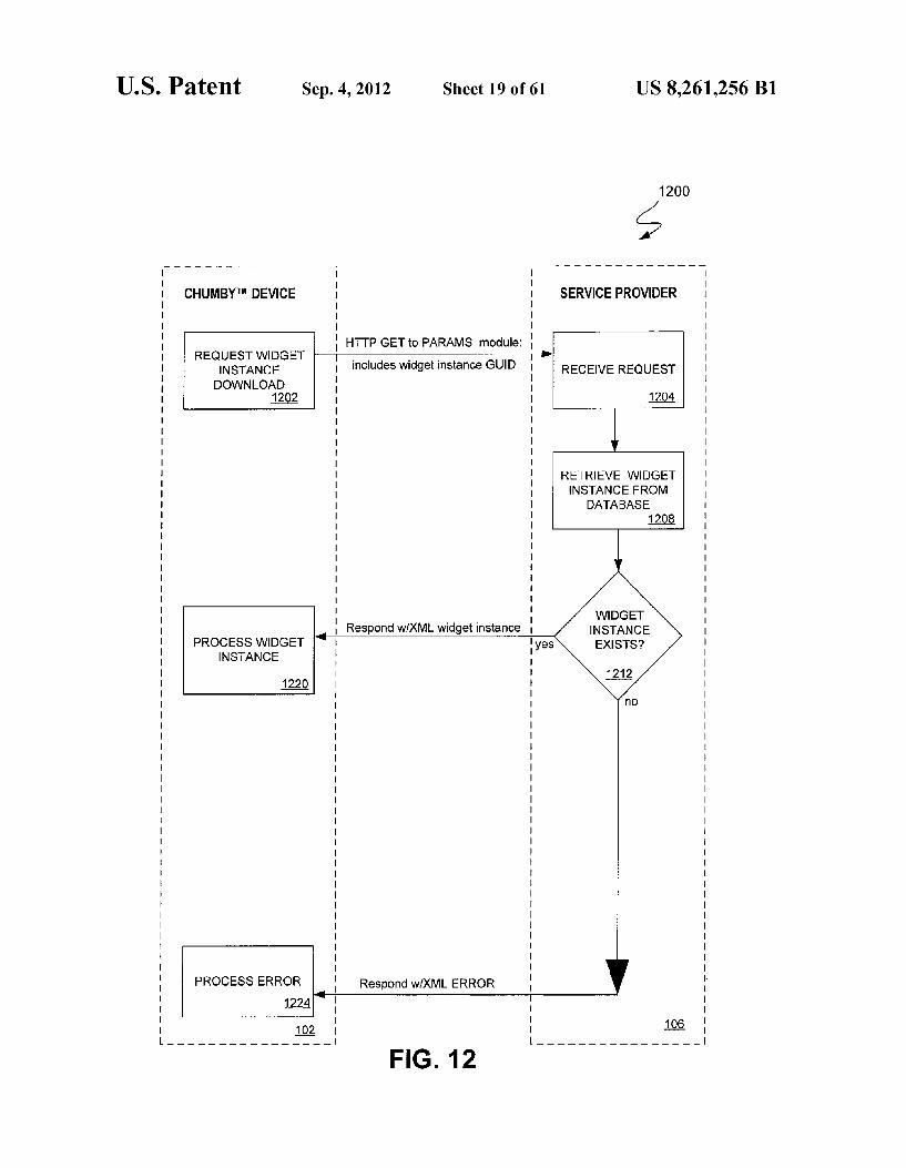
FIG. 12 shows a signal flow diagram illustrating an exem plary widget instance download operation in which a service provider is requested to push values of widget-specific parameters to a requesting CHUMBYTM device.
FIG. 13 is a signal flow diagram which illustratively rep resents the process of obtaining content from the service provider for a widget of a CHUMBYTM device.
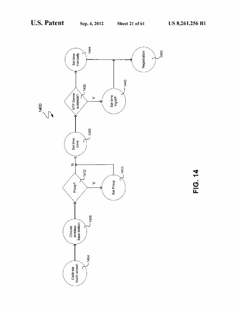
FIG. 14 is a flowchart which depicts an exemplary sequence of operations performed by a CHUMBYTM device upon initial power-up.
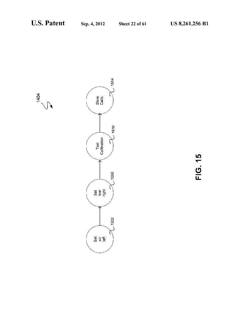
FIG. 15 is a flowchart illustrating an exemplary routine used to calibrate a touchscreen of a CHUMBYTM device.
FIGS. 16A-16D provide a set of screen shots of the user interface of a CHUMBYTM device being calibrated pursuant to the routine of FIG. 15.
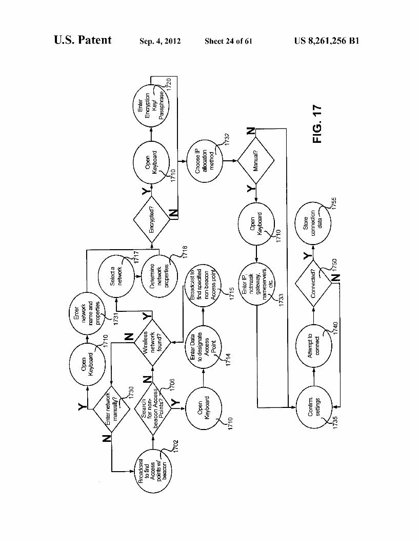
FIG. 17 is a flowchart illustrating the operations performed in selecting a wireless base station upon initial power-up of a CHUMBYTM device.
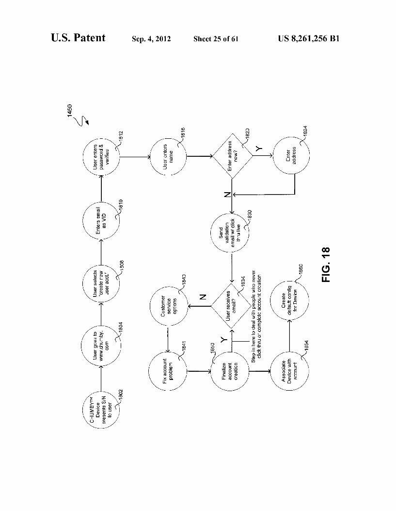
FIG. 18 is a flowchart of an exemplary account creation and registration process.
FIG. 19 is a flowchart representative of an exemplary Web based interaction between a user and a service provider in connection with associating a particular CHUMBYTM device with the user's account.
FIG. 20 is a flowchart of an exemplary Web-based interac tion between a user and the service provider with regard to disabling a CHUMBYTM device that has been previously associated with the user's account.
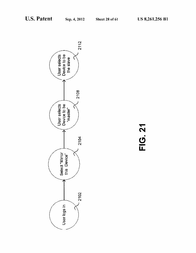
FIG. 21 is a flowchart of an exemplary Web-based interac tion between a user and the service provider in connection with “mirroring CHUMBYTM devices.
5
10
15
25
30
35
40
45
50
55
60
65
4 FIG.22 is a top-level flowchart of exemplary Web-based or
CHUMBYTM device-based interaction between a device user and the service provider with regard to adding, removing and configuring widget profiles relative to the user's CHUMBYTM device.
FIG. 23 is a flowchart representative of exemplary Web based or CHUMBYTM device-based interaction between a device user and the service provider with respect to the addi tion of widgets to the current configuration of the user's CHUMBYTM device.
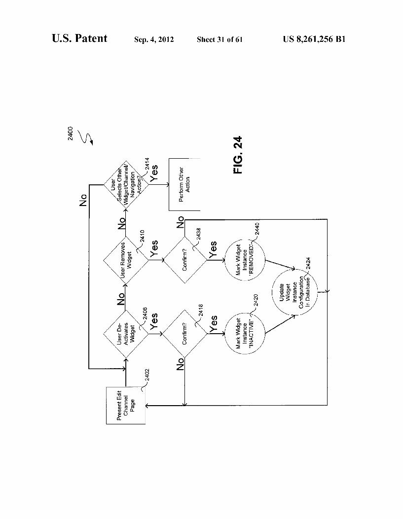
FIG. 24 is a flowchart representative of exemplary Web based or CHUMBYTM device-based interaction between a device user and a service provider in connection with the removal of widgets from a channel, which may also be active on the user’s CHUMBYTM device.
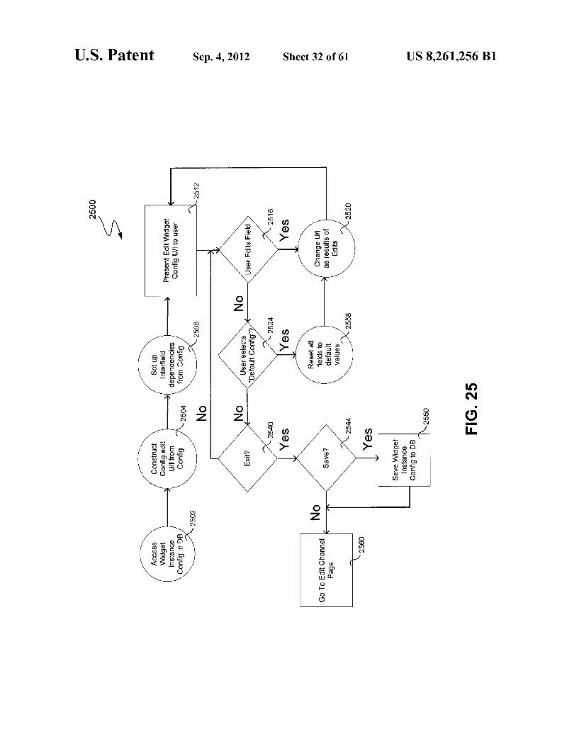
FIG.25 is a flowchart depicting an exemplary set of opera tions involved in configuring parameters specific to of one or more widgets currently associated with a given CHUMBYTM device.
FIGS. 26A-26E are screen shots of exemplary user inter faces presented by a Web browser used to facilitate certain of the processes described by FIGS. 22-25.
FIG. 27 is a signal flow diagram which illustratively rep resents the process of downloading the code for a widget from a service provider.
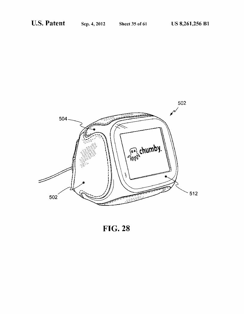
FIG. 28 provides an alternative illustration of a CHUMBYTM device in which is identified a core electronics unit and flexible housing of the device.
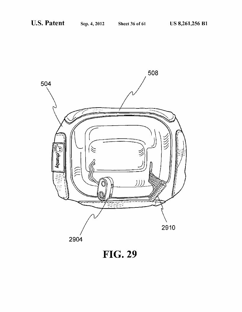
FIG.29 illustrates various components interior to a flexible housing of an exemplary CHUMBYTM device.
FIGS. 30-31 provide an example of a flat pattern used to define the exterior structure of a flexible housing of an exem plary CHUMBYTM device.
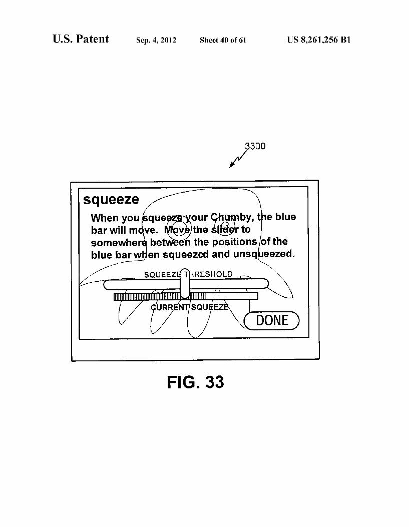
FIGS. 32-33 show exemplary user interface screens of a CHUMBYTM device applicable to a process for calibration of one or more bend sensors within the device.
FIG. 34 is a process flow diagram of a text/image process ing service within the infrastructure of CHUMBYTM service provider configured to parse e-mail messages from mobile devices and extract the relevant content.
FIG. 35 is a process flow diagram illustrating an alternate implementation of an image processing service for CHUMBYTM devices.
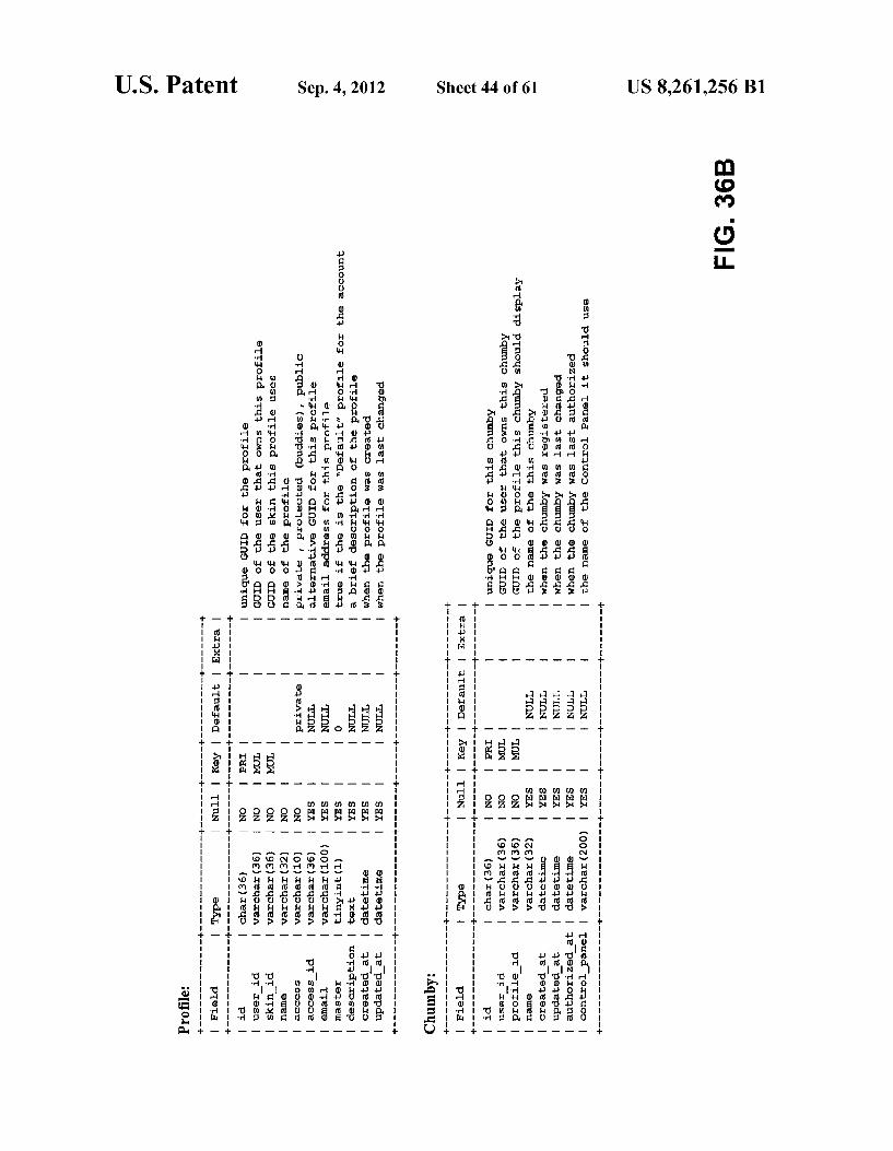
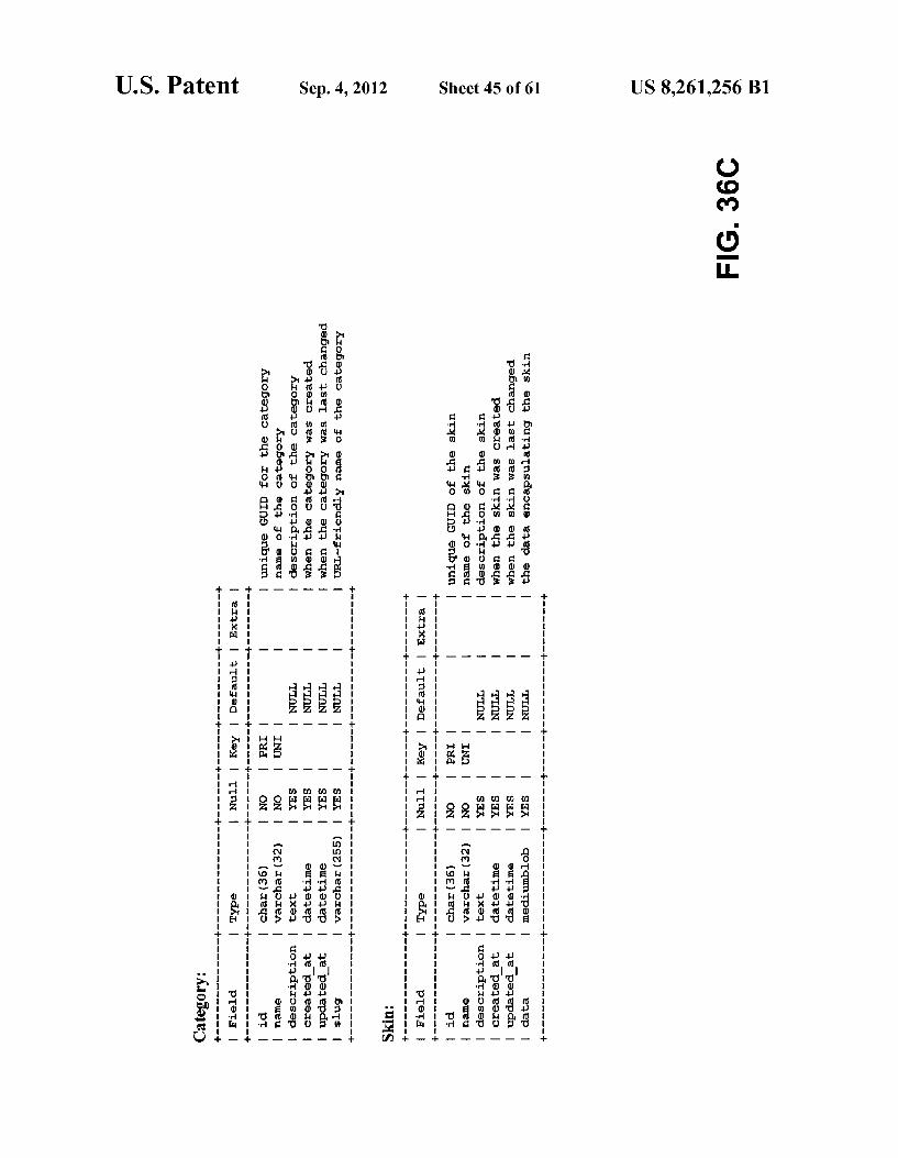
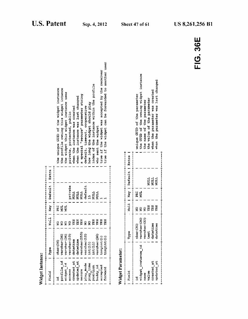
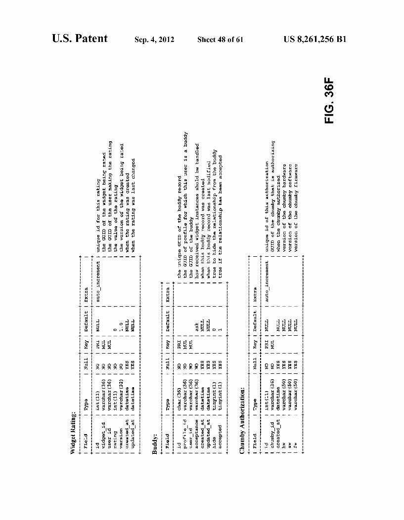
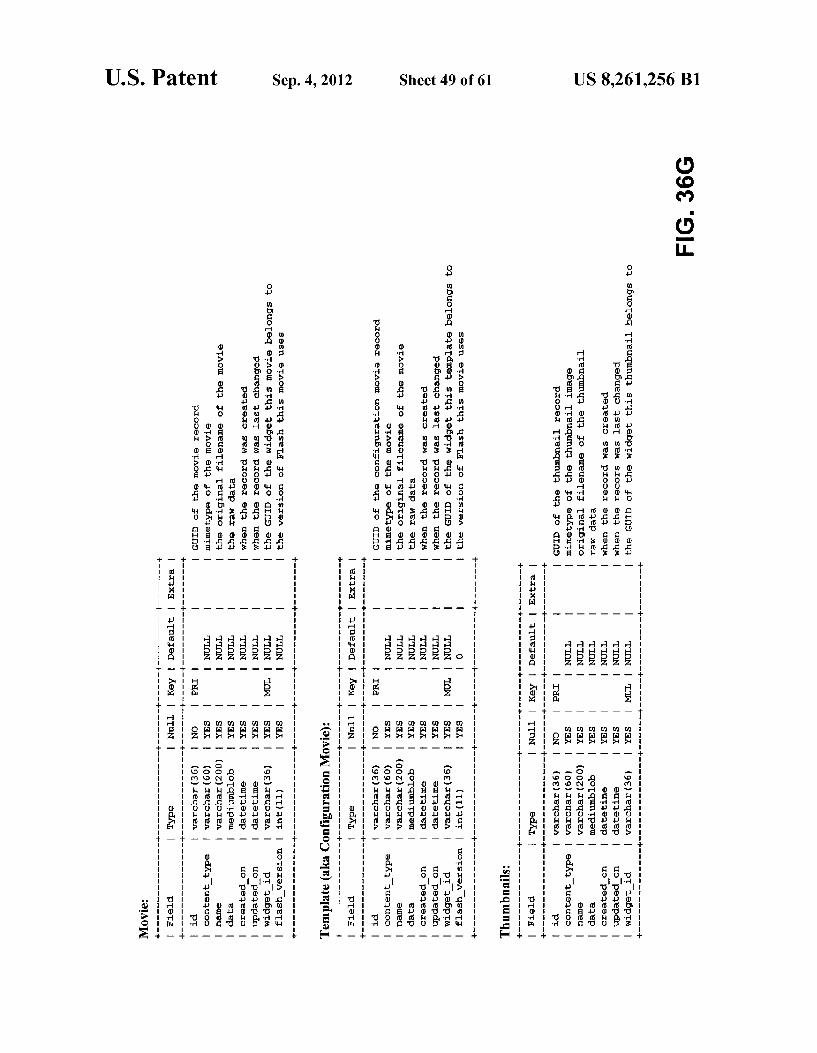
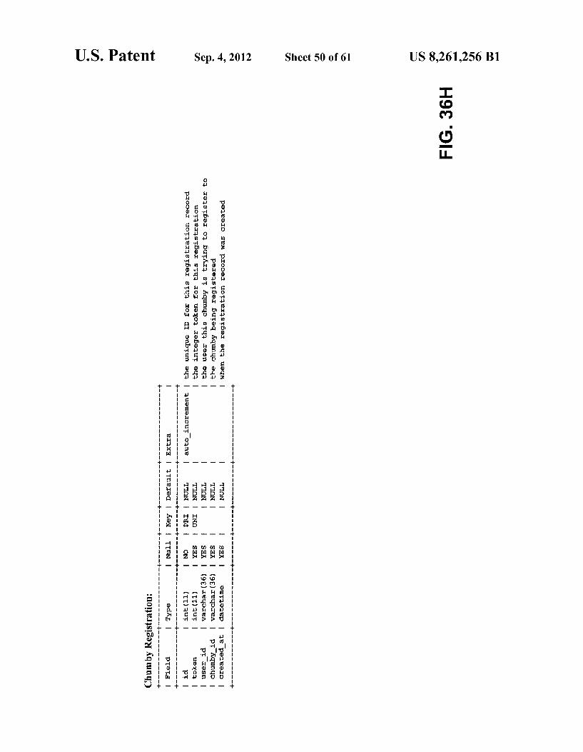
FIGS. 36A-36H provide a more comprehensive tabular representation of an exemplary object-oriented database schema capable of being utilized by the system database.
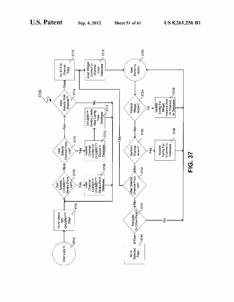
FIG. 37 is a top-level flowchart of exemplary Web-based interaction between a device user and the service provider with regard to adding, removing and configuring widget pro files relative to the user’s CHUMBYTM device.
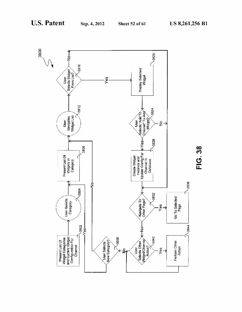
FIG. 38 is a flowchart representative of exemplary Web based interaction between a device user and the service pro vider with respect to the addition of widgets to the current configuration of the user's CHUMBYTM device.
FIGS. 39A-39H are screen shots of exemplary user inter faces presented by a Web browser used to facilitate certain of the processes described by FIGS. 25 and 37-38.
FIGS. 40A-40B are screen shots of exemplary user inter faces presented by a CHUMBYTM device used to facilitate certain of the processes described by FIG. 41.
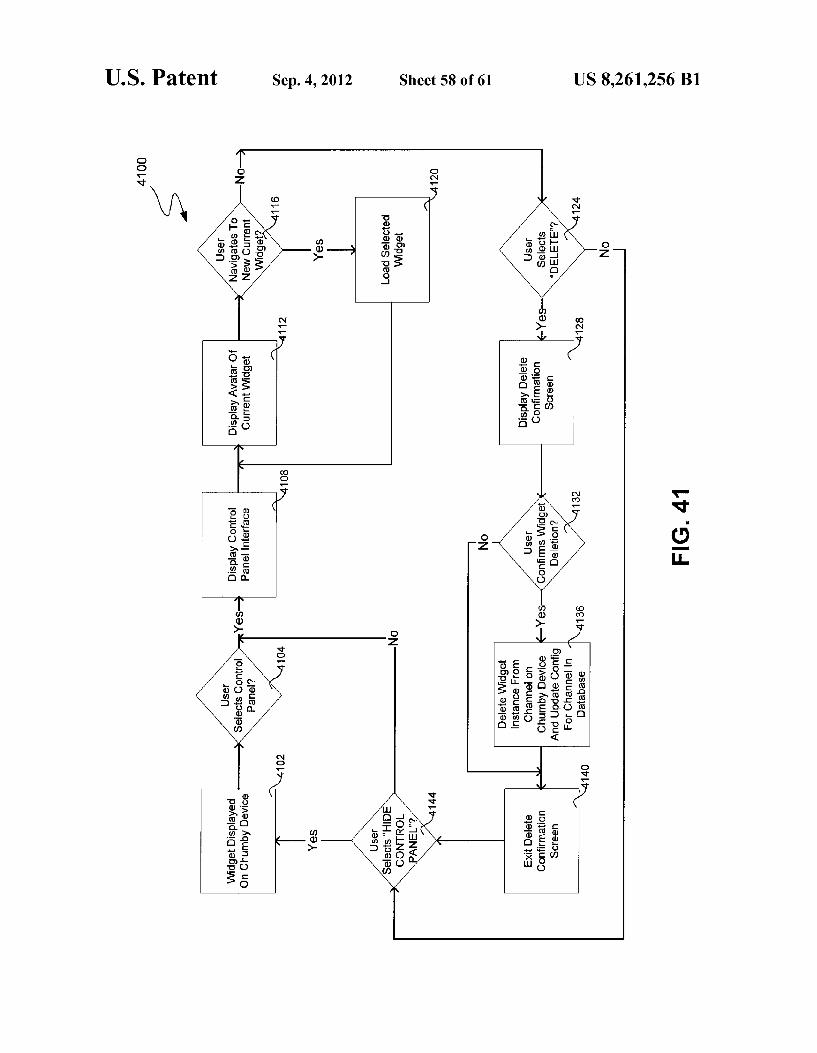
FIG. 41 is a flowchart representative of exemplary CHUMBYTM device-based interaction between a device user and a service provider in connection with the removal of widgets from the current channel of the user's CHUMBYTM device.
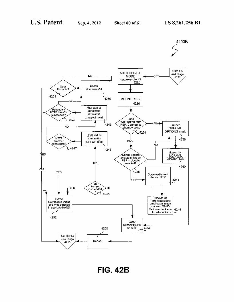
FIGS. 42A-C are flowcharts illustrating an exemplary sequence of operations performed to automatically update all

US 8,261,256 B1 5
or part of the software maintained within non-volatile memory of a CHUMBYTM device.
DETAILED DESCRIPTION OF EMBODIMENTS OF THE INVENTION
Overview
The present invention generally relates a system comprised of a set of personalized audiovisual devices in Internet-based communication with a service provider. It is anticipated that the personalized audiovisual devices will be commercially distributed under the trademark CHUMBYTM, and may also be referred to herein as “CHUMBYTM devices'. During com munication with the service provider, each CHUMBYTM device periodically receives a set of application programs, or “widgets’, which are sequentially executed by the CHUMBYTM device after being received from the service provider or locally from a personal computer (e.g., via a USB connection). Since each CHUMBYTM device is typically Internet-enabled, each may also be remotely configured and otherwise personalized via the CHUMBYTM service provider through a Web browser executed by a remote terminal (e.g., a PC or wireless handset). Such personalization may include, for example, specifying the set of widgets provided to a given CHUMBYTM device as well as their sequence and priority of execution. As is described hereinafter, it is a feature of embodiments
of the invention that a user configuring a CHUMBYTM device via an interface provided by the CHUMBYTM service pro vider may "drag and drop' icons representative of various widgets onto a rectangular or other portion of the interface representative of the screen of the CHUMBYTM device being configured. Alternatively, a user may select textual and/or graphical representations of widgets and select a button or other graphical representation of a user interface (UI) control to “add” the widget to the CHUMBYTM device being config ured. In these ways the “layout of the screen of the CHUMBYTM device may be remotely configured by the owner of the device. Although each CHUMBYTM device will preferably be capable of being configured in this manner, in certain embodiments each may also come “loaded with a default set of widgets (e.g., an "alarm clock' widget) dis posed to be executed by the CHUMBYTM device upon its registration with the CHUMBYTM service provider. Once a CHUMBYTM device has been configured (i.e., with either a “default” or user-specified configuration), it may execute the widgets defined by the configuration without user interven tion. Alternatively, users may opt to “stay on a given widget by explicitly instantiating the system interface on the device and selecting a “stay” UI control. If a user has explicitly selected a widget to “stay”, the sequential execution of wid gets can be continued by terminating the “stay” command via the system interface. If a user interacts with a widget which presents user interface controls to the user through one of a number of alternative input methods. Such as via a touch screen or accelerometer, the currently active widget will con tinue to execute on the device until some timeout period expires following the cessation of user interaction with the widget.
The configuration of a CHUMBYTM device may also specify the events or conditions under which the sequence of execution of widgets is to be altered or interrupted, and allows certain widgets to be accorded the highest available priority with respect to execution. For example, an "alarm clock” widget could be granted Such priority in order to ensure that its alarm function would not be prevented from being actu
10
15
25
30
35
40
45
50
55
60
65
6 ated at the scheduled time due to contemporaneous execution of another widget. In one embodiment the Web interface provided by the CHUMBYTM service provider is in the form of a “timeline' enabling the sequence of execution of the widgets associated with a given CHUMBYTM device to be controlled in an intuitive manner. In an exemplary implemen tation the timeline defines the order in which the widgets are to be played in a constantly repeating sequence; that is, the timeline is representative of the complete set of widgets played by a given CHUMBYTM device as well as their relative order and duration of execution. However, certain widgets (e.g., the "alarm clock' widget) can be specified to be actu ated at a given time by appropriately setting the applicable configuration element of Such widgets.
Although in exemplary embodiments it is not contem plated that more than a single “content-related widget be operative at any given time, a system configuration widget may be utilized to run concurrently with each Such content related widget in order to, for example, control the relative priority of execution of Such content-related widgets and system settings such as loudness, brightness, navigation, and the like.
In one embodiment CHUMBYTM devices are each capable of wireless communication in accordance with an accepted wireless networking standard, such as the 802.11b or 802.11g standard. Accordingly, in homes or other environments con taining one or more wireless access points, multiple CHUMBYTM devices may be distributed throughout the cov erage area of the access points. Alternatively, a CHUMBYTM device may use a wired connection as a backup to, or in lieu of a wireless connection to the extent convenient or neces sary. Among the features of the invention is the capability of the
interface presented by each CHUMBYTM device to change in accordance with the nature of the widget currently being executed by the device. For example, a “clock radio' widget could be employed to produce audio and visual imagery consistent with a conventional alarm clock at an appointed time in the morning. In exemplary embodiments the clock radio widget would allow for the selection of a standard “wake up' chime or choice of several different audio pro grams. Later in the day the device interface could be devoted to a rotating selection of several standard information screens Such as news headlines, local weather, sports scores, Stock market updates, horoscope and the like.
In accordance with another aspect of the invention, users of CHUMBYTM devices may optionally participate in a “CHUMBYTM Network” along with other users by logging on to a Web site (e.g., www.chumby.com) hosted by the CHUMBYTM service provider. At this site (also referred to hereinafter as the “CHUMBYTM site') a user will be able to register with the CHUMBYTM Network and access services enabling the basic capabilities of the user's CHUMBYTM device. Basic capabilities may comprise, for example, the opportunity to send/receive widgets and other content to/from other CHUMBYTM users, for improved personalization of the device's generic information features, more detailed alarm setting capabilities, and better selection and configuration of audio capabilities.
Registration with the CHUMBYTM Network, which would potentially require payment of a periodic Subscription fee, enables members of the Network to access a wide array of widgets. It is contemplated that certain of such widgets would be developed by the entity operating the CHUMBYTM Net work while other widgets would be developed by indepen dent developers. In addition, members of the “CHUMBYTM Network would also be able to communicate with the
US 8,261,256 B1 7
CHUMBYTM devices of other members, provided that per mission for Such communication has been authorized by the other members. Such communication could entail, for example, the sending of a widget and corresponding data from the CHUMBYTM service provider to a member of the CHUMBYTM Network (the “receiving member”) in response to a request sent to the CHUMBYTM service provider by another member (the “sending member). For example, a sending member could, after receiving permission from a receiving member, request the CHUMBYTM service provider to send a “photo-viewer' widget to the receiving member. In addition, the sending member could specify that a link be established between the photo-viewer widget and pictures uploaded by the sending member to the CHUMBYTM service provider. In this way the receiving member could, without any effort other than providing authorization to the sending mem ber, enable their CHUMBYTM device to essentially automati cally receive and display a sequence of photos provided by the sending member. Similarly, while traveling a sending mem ber could send a personalized “wake up” message to the CHUMBYTM device of a consenting receiving member. Finally, a sending member could send widgets to a group of receiving members included on a “buddy list of the sending member, which could be established after the receipt of suit able permissions from those proposed to be included on the list.
In an exemplary embodiment members of the CHUMBYTM Network are enabled to completely configure, through any Web browser, their respective CHUMBYTM devices by specifying a set of "premium' widget programs or content to play or be shown rotationally (or in some other user-defined sequence) on their respective CHUMBYTM devices. Such premium widgets and content may include, for example, webcam shots, RSS readers, filtered news reports, personalized stock performance data, short animations or movies, podcasts or audio files to function as the audio Sources for alarms or reminders scheduled to be triggered at different times throughout the day. As is discussed further below, one exemplary implemen
tation of a CHUMBYTM device is comprised of a malleable housing attached to a rigid “core' structure Supporting a display Screen and the electrical components of the device. The malleable housing would generally encompass all of the electrical components of the CHUMBYTM device, and will preferably be filled with an appropriate material or otherwise constructed to enable it to be “squeezed' or otherwise deformed by a user. Moreover, the core structure is designed to be capable of being removed from the housing and mated in to a different housing. A set of "squeeze sensors' are enclosed by the malleable housing in order to permit the detection of Such a squeezing or similar action by a user. In this way a user is afforded the opportunity of conveying information through physical deformation of the CHUMBYTM device in addition to the more conventional textual and other modes of communication facilitated by the display Screen. For example, in one exemplary system a user could initiate the conveying of a 'hug' to another user by squeezing the housing of the user's CHUMBYTM device in a particular manner. The electrical signals generated by the sensor array in response to this squeeze would be appropri ately interpreted and the user's CHUMBYTM device would communicate, via the CHUMBYTM service provider, a “hug” message to the intended recipient user. At this point the recipi ent’s CHUMBYTM device could register receipt of the hug message by, for example, illuminating an indicator light or sending a message to the display of the device. Significantly, the CHUMBYTM device is not limited to an implementation
10
15
25
30
35
40
45
50
55
60
65
8 in a malleable housing; all of the features associated with Such a malleable housing may be emulated using a rigid housing in combination with alternative sensors (e.g., force-sensitive or virtually emulated sensors).
System Components
FIG. 1 is a block diagram illustrating a set of networked components comprising an exemplary embodiment of the system 100 of the invention. As shown, the system 100 com prises one or more CHUMBYTM personal audiovisual devices 102 in communication with a central service provider 106 via one or more access networks 110 and the Internet 116. As those skilled in the art will appreciate, the access networks 110 are representative of various intermediary network rout ing and other elements between the Internet 116 and the CHUMBYTM personal audiovisual devices 102. Such inter mediary elements may include, for example, gateways or other server devices, and other network infrastructure pro vided by Internet service providers (ISPs). As is discussed below, the CHUMBYTM personal audiovisual devices 102 obtain application programs (“widgets’) for execution from the central service provider 106 or locally from a mass storage device, personal computer or other computing device. In this regard the service provider 106 typically contains a repository of widgets and has access to other content capable of being communicated to a given CHUMBYTM device 102 upon the request of its authorized user or another user to which appro priate permission has been granted.
Referring again to FIG. 1, the system 100 also includes a plurality of user computers 120 disposed for communication with the service provider 106 via an access network (not shown) and the Internet 116. Each user computer 120 executes a Web browser 122 capable of displaying Web pages generated by the service provider 106 through which a user may configure one or more CHUMBYTM personal audiovi Sual devices 102. As mentioned above, such configuration may include, for example, specifying a set of widgets to be sent to a particular device 102 and their sequence of execu tion, adjusting audio or visual parameters relating to Such execution, defining and managing a user's CHUMBYTM net work (including, for example, defining a “buddy list com prised of other CHUMBYTM users with respect to which the device 102 is permitted to communicate), and defining the layout or other aspects of the user interface presented through the screen of the device 102. To this end a given Web browser 122 may, when in communication with the service provider 106, present a rectangular configuration window which dis plays the widgets currently configured to “play' within the named “channel. By 'dragging and dropping iconic repre sentations of widgets or content files into Such a configuration window, a user may personalize the behavior and user inter face presented by the corresponding CHUMBYTM device 102. Alternatively, a user may select textual and/or graphical representations of widgets and select a button or other graphi cal representation of a user interface control to “add the widget to the CHUMBYTM device being configured. More over, users may access the service provider 106 via a Web browser 122 for the purpose of sending widgets or other information to other users for execution or display by their respective CHUMBYTM devices 102. In one embodiment the service provider 106 maintains a record of the permissions granted among users of CHUMBYTM devices in order to determine which users are authorized to provide, via the service provider 106, a given user with widgets, messages or other information, and Vice-versa. Such permissions may be

US 8,261,256 B1 9
granted or withdrawn by a given user via appropriate pages presented by a Web browser 122 in communication with the service provider 106.
In the exemplary embodiment a configuration window may be utilized to configure one or more CHUMBYTM devices 102 consistent with the permissions granted by the users of such devices 102. In addition, a user of a given CHUMBYTM device 102 may elect to have the interface of the device 102 “mirror” or otherwise replicate that of another device 102 Subject to the requisite permissions being granted. Similarly, one or more CHUMBYTM devices 102 may be configured to mirror the interface for a “virtual” CHUMBYTM device (or Vice-versa) defined via a configuration window.
Different users of a given CHUMBYTM device 102 may be accorded different roles or privileges in configuring the device 102. For example, user-granted Supervisory privileges could be given the authority to filter or monitor the widgets or content sent to the CHUMBYTM device 102. This would enable, for example, parents to manage and/or monitor the widgets and content executed and displayed by the one or more CHUMBYTM devices 102 used by their children. More over, administrators of the system 100 would typically pos sess an elevated level of privilege relative to users of CHUMBYTM devices 102 within the system 100. Also, if a specific widget performs functions requiring communication with a web site controlled by a third party in order to access content, the developer of the widget may create a hierarchical user model to regulate such access (and perhaps the functions of the widget).
Attention is now directed to FIG. 2, which illustrates an exemplary distribution of CHUMBYTM devices 102 through out a residence 200 or other building having a number of rooms 204. In the embodiment of FIG. 2, each CHUMBYTM device 102 is equipped with wireless transceiver (e.g., a Wi-Fi transceiver) to facilitate communication with one or more access points 210. Each access point is interconnected with an access network 110 by way of for example, a local area network, thereby enabling Internet-based communication to be established between the service provider 106 and the devices within the residence 200.
Turning now to FIG. 3, a block diagrammatic representa tion is provided of the principal components of an embodi ment of a CHUMBYTM device of the present invention. As shown, the device includes a central processing unit (CPU) 302, memory including volatile (e.g., SDRAM) 306 and non Volatile memory 310 (e.g., flash memory), an audio interface 312, a wireless communications interface 314, and a sensor interface 370. In an exemplary implementation the CPU 302 comprises a microprocessor (e.g., based upon an ARM core) configured to run a Linux kernel and having attendant capa bilities for graphics rendering. The device may or may not include a battery backup unit, which serves to preserve real time information in the event of a power outage, and may also serve as a primary power source if the user desires untethered operation. The battery may or may not be rechargeable. The operating system is made aware of the power status and actively configures the CHUMBYTM device and the running widget to either save power or modify the user interface consistent with untethered operation. The device may or may not include a Security Module (not
shown) If included, the Security Module serves to store secrets and compute authentication algorithms in a fashion that fully isolates core security routines from otherwise unse cured code running on CPU 302. The secret storage and authentication capability may or may not be used by the client-server communication protocol to enable authenticated and encrypted communication capabilities for, among other
5
10
15
25
30
35
40
45
50
55
60
65
10 things, financial transactions. The Security Module is initial ized in Such a way that there is no default mapping of the secrets contained within the module versus the identity of the hardware of the user. Furthermore, the secrets are revocable and a routine may exist for generating new secrets based upon a master secret that is never associated with a specific user's profile. This enables opt-in policies for privacy and a limited ability to revoke identity information, barring forensic net work analysis, thereby enabling anonymity as well. The anonymous trust network can be extended with a variety of client-server protocols to enable a wide range of anonymous transactions, including but not limited to cash and content transactions. As shown, software comprising widgets 350 or other appli
cations received from the service provider 106 are stored in memory 310 and loaded into SDRAM 306 or non-volatile memory 310 for execution by the CPU 302. In one embodi ment widgets are downloaded from the service provider 106 to CHUMBYTM devices in the format of a “Adobe Flash' file, also referred to as a “Flash movie'. As is known by those skilled in the art, Flash movies are usually accorded a “...swf: file extension and may be played by a Flash Player developed and distributed by Adobe Systems. Accordingly, the memory 310 also includes a Flash Player 360 as well as a copy of the operating system 364 executed by the CPU 302. In other embodiments widgets may be developed in accordance with other formats and played by players compatible with such other formats.
In the exemplary embodiment widgets are not “perma nently stored in memory 310 of CHUMBYTM devices. Rather, widgets are executed by the CPU and then either discarded or cached in temporary memory for future use. This enables widgets to be “pushed' from the service provider 106 as necessary to Support the sequence of widget execution specified for each CHUMBYTM device. That is, the service provider 106 may operate to provide a “stream” of widgets to each CHUMBYTM device, where the widgets within each Such stream are temporarily cached within the memory of the applicable CHUMBYTM device until their execution. This enables the service provider 106 and/or the creator of each widget program to maintain a degree of control over the content and behavior of each widget program, since each Such program is typically not permanently downloaded (thereby facilitating modification) but is rather temporarily cached and erased after Some predetermined time has passed or a memory use threshold has been reached. The CHUMBYTM device also includes a liquid crystal
display (LCD) 320 controlled by an LCD controller 322, which may or may not be integrated into the CPU 302. The display 320 visually renders iconic representations of the widget programs stored within the CHUMBYTM device and images generated in connection with the execution of Such widgets by the CPU 302. In an exemplary implementation a touchscreen 330 overlays the LCD 320 and is responsive to a touchscreen controller 334. In one embodiment a user may induce the CHUMBYTM device to enter a “control panel mode” by touching the a sensor Such as the Squeeze sensor (not shown in FIG.3), touchscreen 330 or other sensor device. In an exemplary embodiment, widgets and the system control panel may present the user with different “user interface', or “UI”, elements to enable the user to interact with the widget/ system control panel. These UI elements may include, but are not limited to, buttons, scroll bars, drop down combo boxes and menus. When a user touches the screen to interact with one of these UI elements, the touchscreen controller 334 informs the CPU 302 that the touchscreen has been touched at a specific location and that location is converted by the CPU

US 8,261,256 B1 11
302 to a UI control actuation event based on the configuration of the currently displayed widget 350 or system control panel screen (not shown in FIG.3). In alternate implementations the LCD 320 and touchscreen 330 may comprise an integral device controlled by an integrated controller.
Turning to FIG. 4, there is shown an exemplary user inter face 400 generated by the LCD 320 during operation of the CHUMBYTM device in control panel mode. As shown, the interface 400 defines an mute button 404, a channel button 406, a night button 408, a music button 410, a settings button 412, a clockbutton 414, a delete button 418, a rate button 420, a send button 422, a stay button 424, a rightarrow button 428, a left arrow button 426, and a hide control panel mode button 416. Selection of the mute button 404 toggles the mute state of the CHUMBYTM device. Selection of the channel button 406 instantiates another control panel screen which enables users to view the content of all of their CHUMBYTM “chan nels' and/or select a new "channel to be loaded and run on the CHUMBYTM device. A “channel is a collection of wid gets configured by a user in a named grouping via an inter action between a page rendered on a web browser 122 and the CHUMBYTM service provider, such collection of widgets generally running on the CHUMBYTM device in a sequential, repetitive fashion.
Selection of the night button 408 places the CHUMBYTM device into a “night mode” in which the screen is dimmed and a low intensity clock is displayed. Selection of the music button 410 instantiates another control panel screen which enables the user to interact with and control various continu ous music sources, such as, for example, MP3 players, Stor age devices, and music services. Such sources may reside on either the local network or on the Internet. Selection of the settings button 412 instantiates another control panel Screen which enables the user to configure various CHUMBYTM device settings, such as, for example, wireless network setup, speaker volume and touchscreen calibration. Selection of the clock button 414 instantiates another control panel Screen which enables the user to configure the time, date and alarm functions of CHUMBYTM device. Selection of the delete button 418 deletes the currently displayed widget to be deleted, with user confirmation, from the current “channel'. Selection of the rate button 420 instantiates another control panel Screen which enables the user to provide a rating on a fixed scale for the currently displayed widget. Selection of the send button icon 422 instantiates another control panel Screen which displays a personalized list of other users of CHUMBYTM users to which it may be desired to send widgets or otherwise communicate. Selection of the stay button 424 toggles the “stay” state of the currently selected widget. When the “stay” state of a widget is selected, the widget plays continuously on the CHUMBYTM device. Selection of the right arrow button 426 or left arrow button 428 causes the CHUMBYTM device to display the previous or next widget in the channel, respectively. A user may, from any Web browser 122, access a Web page generated by the service provider 106 and designate a “favorite widget. Alternatively, a user may press a virtual, touchscreen-based button on his or her CHUMBYTM device 102 to designate the current widget as the new “favorite' widget. When the user then selects the heart-shaped icon (not shown in FIG. 4) on his or her CHUMBYTM device, an iconic representation of this favorite widget (e.g., a clock widget) replaces the heart-shaped icon and enables the user to immediately activate (i.e., cause the CPU 302 to execute) the program instructions corresponding to such favorite widget. Alternatively, selection of the heart shaped icon (or other predefined icon) results in the CHUMBYTM device becoming configured in accordance
10
15
25
30
35
40
45
50
55
60
65
12 with a “favorite' or other profile rather than executing a favorite widget. Of course, certain profiles may be specified to include only a single widget such as, for example, an “alarm clock” or “photo viewer widget.
Referring again to FIG. 4, selection of the right arrow button 426 advances one widget in a user-defined (or default) widget sequence (“channel'), or just skips ahead in imple mentations in which widgets are chosen to be displayed ran domly. Similarly, selection of the left arrow button 428 results in “going back' one widget in the user-defined (or default) widget sequence (“channel'). As the buttons 426 and 428 are selected, an iconic representation or avatar corresponding to the currently active widget is displayed in a display box 430. If it is desired to return to the currently active widget, the hide control panel mode button 416 is selected and the control panel mode interface 400 changes to a screen through which the user views the sequence of widgets currently configured to be executing on the CHUMBYTM device.
In certain embodiments a physical button element (not shown) may be provided proximate the LCD screen 320 to enable navigation through menus and the like presented by the LCD screen 320. In one implementation this button ele ment is cross-shaped in order to facilitate two-dimensional navigation, and may further include a smaller, dedicated but ton (e.g., in the center of the cross) associated with a specific widget (e.g., clock widget). Pressing this dedicated widget would interrupt the operation of all other widgets.
In implementations in which two-dimensional navigation through the user interface of the CHUMBYTM device is sup ported, users may be provided with the ability to navigate forward and back in the configured widget timeline. Simi larly, users may navigate up and down a stack of related widgets. This function depends on the implementation of the concept of widget categories—i.e., associating widgets into logical categories that can be displayed sequentially, if con figured to be displayed. An example of a category could be “News”. Widgets included within this category could include, for example, a local news widget, a sports news widget, an entertainment news widget, a business news widget, and the like. For each category, there would be a default widget, which is designated by the user on the CHUMBYTM web site for each category selected to be displayed by the user's CHUMBYTM device.
If more than one widget in a category is selected, then the widgets are conceptually “stacked with the default widget being:
on the top of the stack; and the widget that is displayed as the CHUMBYTM device
automatically cycles through configured widgets. If a widget for a given category (e.g., “News’) is displayed
and there exist additional widgets in the category which are also configured for display, then in the exemplary embodi ment these additional widgets are “stacked' below the dis played widget. In this case the user may take some predefined action with respect to the user's CHUMBYTM device (e.g., perhaps selecting a control on the touchscreen or accessing a function via the control panel, which is instantiated via actu ating the Squeeze sensor) in order to cause the next widget in the "stack' for that category to be displayed. The CHUMBYTM device may be configured such that taking fur ther predefined actions of the same type will cause the wid gets either above or below in the stack to be displayed, as designated by the user. The last widget that is displayed in the stack for the applicable category when the CHUMBYTM device cycles to the next widget category will be the widget displayed in the next cycle for the just exited category (e.g., News).
US 8,261,256 B1 13
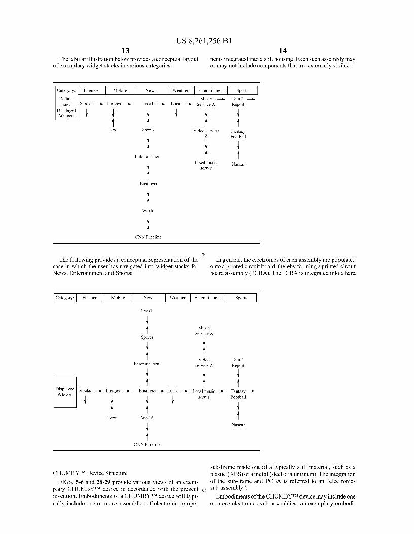
The tabular illustration below provides a conceptual layout of exemplary widget Stacks in various categories:
14 nents integrated into a soft housing. Each Such assembly may or may not include components that are externally visible.
Music Local -> Local -> Service X Stocks -- Images -a-
Surf -- Report
ent
-e-
"WE" A
Text Sports Video service Fantasy y Z Football
A y Entertainment
Business
: World
y A
CNN Pipeline
30 The following provides a conceptual representation of the
case in which the user has navigated into widget stacks for News, Entertainment and Sports:
Local music Sewer
Nascar
In general, the electronics of each assembly are populated onto a printed circuit board, thereby forming a printed circuit board assembly (PCBA). The PCBA is integrated into a hard
Local
Music
Video Entertainment
y
PSPlayed Stocks -- Images -- Widget: y y Sewer y
Text World
CNN Pipeline
CHUMBYTM Device Structure
FIGS. 5-6 and 28-29 provide various views of an exem plary CHUMBYTM device in accordance with the present 65 invention. Embodiments of a CHUMBYTM device will typi cally include one or more assemblies of electronic compo
service Z.
Service X
Surf Report
Business-> Local -> Local music-> Fantasy --> Football
Nascar
Sub-frame made out of a typically stiff material. Such as a plastic (ABS) or a metal (steel or aluminum). The integration of the sub-frame and PCBA is referred to an “electronics sub-assembly'. Embodiments of the CHUMBYTM device may include one
or more electronics Sub-assemblies; an exemplary embodi
US 8,261,256 B1 15
ment described herein employs three such sub-assemblies. One such sub-assembly is included within a core electronics unit of the CHUMBYTM device, and contains heat-generating electronics components, an LCD, and a microphone. Another such electronic sub-assembly comprises a WiFi riser contain ing a WiFi communications module. The third electronics sub-assembly included within the exemplary embodiment of the CHUMBYTM device comprises a “daughtercard sub-as sembly'. The daughtercard contains a plurality of external connectors (e.g., USB connectors) and a set of audio trans ducers. In the exemplary embodiment a mechanical Switch is grafted onto the daughtercard Sub-assembly facilitates the 'Squeeze sensing described below. An accelerometer may also be included upon the daughtercard Sub-assembly. The general subdivision into these three sub-assemblies
confers several benefits. By confining the heat generating components to the core electronics unit and WiFi riser, a more cost-effective heat path may be engineered. By confining the connectors and large transducers to the daughtercard, logis tical advantages may be conferred to the Supply chain. This may add a new level of rapid reconfigurability of the CHUMBYTM device for end user customization. By bridging between the sub-assemblies with flexible connectors, the CHUMBYTM device retains a soft and flexible feel.
Attention is now directed to FIG.5, which provides various perspective views of an exemplary CHUMBYTM device con figured with a malleable housing 502 comprising a rubber type frame 504 in combination with a fabric material 508. The housing 502 surrounds a core electronics unit 512, bezel 514 for daughtercard Sub-assembly, and a plush interior fill mate rial (not shown in FIG. 5). The frame 504, fabric 508 and fill materials collectively imparta soft and malleable feel to users handling the CHUMBYTM device.
In one embodiment the frame 504 is composed of Santo preneTM or Texin, a soft, flexible, tactile, rubber-like material similar to TPE (thermoplastic elastomer). In another embodi ment, the frame 504 is composed of a very low durometer PVC (Polyvinyl Chlroide). The exact frame composition will generally balance considerations of flexibility, feel, look, and manufacturing properties, namely, the ability to be sewn and to have items tacked onto the side with adhesive to improve production tolerances. The frame 504 provides structure and form to the housing 502 and allows the core electronics unit 512 to be replaced and inserted. The frame 504 will generally be manufactured in a relatively flattened configuration and then manually flexed or curved and stitched to the fabric or other soft material when assembling the housing 502 of the CHUMBYTM device. In another embodiment, the CHUMBYTM frame, fabric, or a combination thereof is cre ated out of molded EVA (Ethylene VinylAcetate) foam. The molding process renders a slightly different feel but generally provides greater fidelity to CAD-related artwork.
FIG. 28 provides an alternative illustration of a CHUMBYTM device in which are identified the core electron ics unit 512 and the flexible housing 502. As opposed to existing wireless or other consumer electronic devices in which the device electronics are typically simply mounted into rigid plastic enclosures that are not subject to any user modification or customization, in an exemplary embodiment the flexible housing of a CHUMBYTM device may be created using any number of exterior fabric materials such as those used in soft-goods or plush toy manufacturing. Such materi als may include, for example, leather, Suede, Neoprene, rub ber, vinyl, etc. Interior to the flexible housing may be con tained any number offill materials, such as Poly-Fil, polyester beads, gel, foam, metal beads, etc., not unlike a pillow, stuffed animal, or plush toy. Such interior fills enable the
10
15
25
30
35
40
45
50
55
60
65
16 CHUMBYTM device to be “squishable.” Moreover, such inte rior fill enables the device to retain its shape after being “squeezed' or “pressed by a user in order to trigger an internal squeeze sensor 650. (In other embodiments an elec tric field/capacitance sensor may be used in lieu of a squeeze sensor to detect the location/distance of a user's hand to the sensor; that is, since the users hand moves closer to the sensor as the user Squeezes the flexible housing of the CHUMBYTM device, the sensor is capable of indicating that a “squeeze' event has occurred).
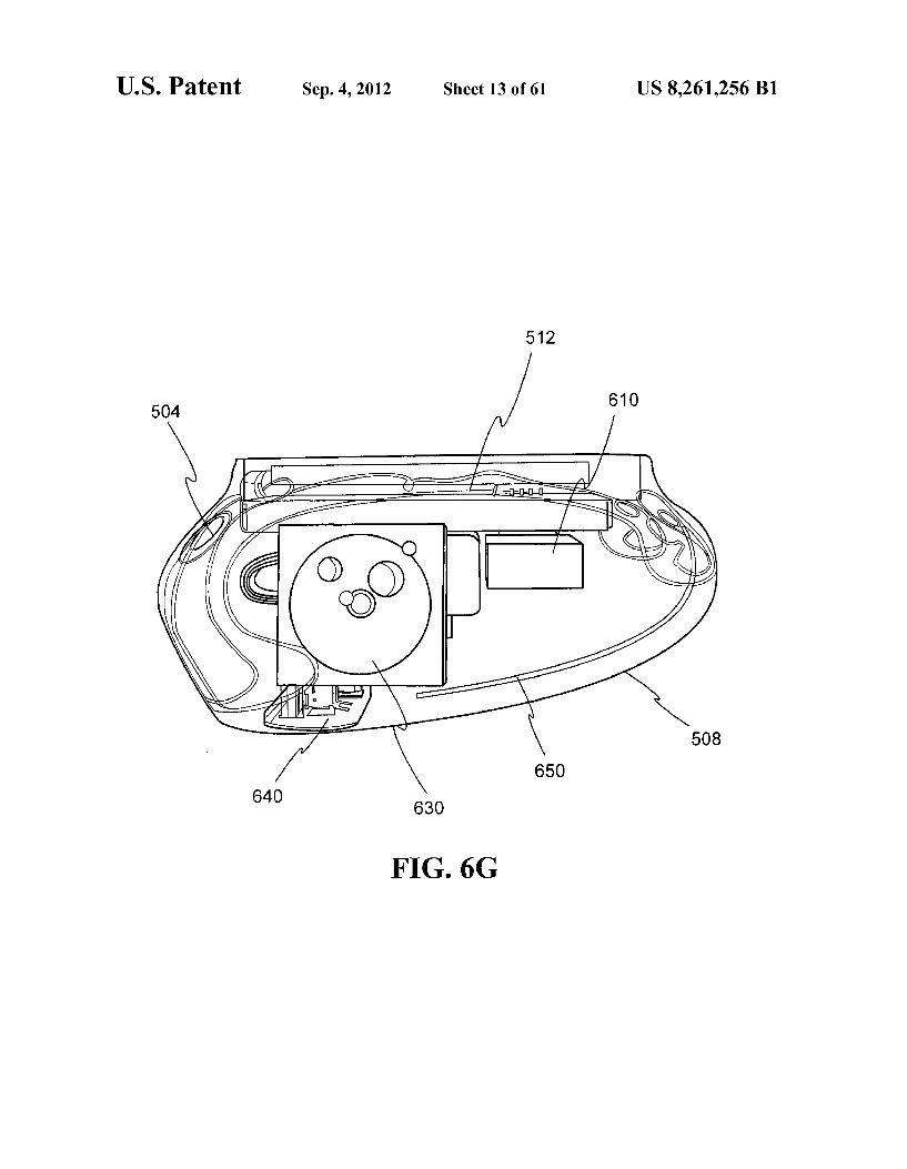
Turning now to FIG. 29, interior to the flexible housing of an exemplary embodiment of the device there is included the daughtercard circuitry containing an external power Switch, external power Supply connector, external headphone con nector, one or more external USB connectors, internal left and right speaker connectors, internal 9V back-up battery con nector 2904, internal Squeeze sensor connector, and internal cable assembly or “ChumbilicalTM connector 2910. In one implementation the Chumbilical connector 2910 is used to connect all the signals received/processed by the daughter card sub-assembly to the core electronics unit 512 of the CHUMBYTM device, which is press-fit into the soft frame. Also positioned interior to the flexible housing are a pair of speakers 630 (for left and right audio output) (FIG. 6F), as well as a squeeze sensor 650 (FIG. 6G) and various cabling required to attach Such elements to the daughtercard Sub assembly 640. In the preferred embodiment, the speakers are affixed to a rigid plate, constructed of plastic or other similar material, located on the back of the CHUMBYTM device, coincident to the headphone connector, USB ports, power Switch and power connector. The division of the circuitry into a core board with greater
complexity and cost and a daughtercard which breaks out many of the peripheral connections and features is a signifi cant feature of the design of exemplary embodiments of the CHUMBYTM device. So segregating the design enables quicker adaptation to market and product changes, since the most volatile components of a system are often “on the edge'. The segregation of the core and the peripherals in this manner also provides a key benefit, in that the peripheral card can be customized at a lower cost, which helps enable the growth of an ecosystem of accessories and custom housings around the CHUMBYTM device.
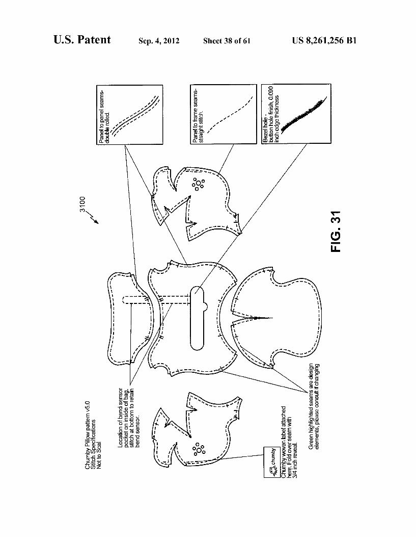
Referring to FIGS. 30-31, an example of a flat pattern, commonly used in Soft-goods and garment manufacturing, is used to define the exterior structure of the flexible housing 3002 or “bag” of an exemplary CHUMBYTM device (“CHUMBYTM bag”). Any number of artistic/design ele ments can be added to the exterior fabric material of the CHUMBYTM bag to add dimension and visual features. The use of a fabric-type enclosure for the CHUMBYTM device provides for unlimited possibilities for product housing cre ation, both by the original manufacturer and end-users (such as craftspeople, hobbyists, etc.), and is believed to representa novel approach in the design of consumer electronic and/or wireless devices. Fabric tags, patches, or other fabric/gar ment-related items can be stitched or otherwise attached to the exterior housing of the CHUMBYTM device to convey product or corporate information, such as a logo.
FIG.31 provides a sample flat pattern drawing 3100 for the flexible housing 3002 or “bag” of a CHUMBYTM device, showing individual fabric panel shapes, Stitching details, and design elements:
FIGS. 6A-6D provide various partially transparent per spective, side and plan views of an embodiment of the CHUMBYTM device. FIGS. 6E-6F depict the core electronics unit and other components contained within the housing of
US 8,261,256 B1 17
the CHUMBYTM device, and FIG. 6G illustrates the arrange ment of certain of these elements within the housing. The core electronics unit 512 will generally include, for
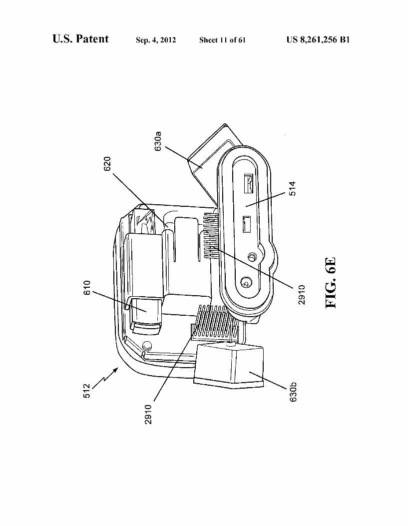
example, a main circuit board onto which are populated a plurality of electronic components. The main circuit board will generally then be integrated into a hard Sub-frame made of a rigid material Such as, for example, stiff plastic or metal, thereby yielding an electronics sub-assembly. The core elec tronics unit 512 will also typically include an LCD display, touchscreen, ambient light sensor, microphone, USB WiFi dongle 610, backup battery 620, and any number of RF shields. This core module is designed to be removable from the frame by the user of the CHUMBYTM device. It is typi cally connected into the housing CHUMBYTM by the Chum bilicalTM connector 2910.
The WiFi dongle 610 is connected to the WiFi riser (not shown) of the core electronics unit and facilitates WiFi wire less networking. The backup battery 620 may be realized using, for
example, a standard 9V alkaline, and is used to provide backup/supplemental power to the CHUMBYTM device in the event of failure of the primary power supply. In one embodi ment, the backup battery 620 is mounted onto an RF shield positioned on a back side of the core electronics unit 512 and is intended to be replaceable by the user. In another embodi ment, the battery 620 is contained in the soft housing of the CHUMBYTM device and is accessible via a velcro-sealed hole in the exterior material for user service.
In the exemplary embodiment the daughtercard 640 pro vides connectors available to the user, including power input, headphone output, and external USB-style connectors for future accessories and/or facilitating device upgrades. The daughtercard sub-assembly 640 is clamped to the fabric in between the daughtercard sub-assembly front and rear bezel components 514, which are made of rigid ABS-type plastic. The daughtercard Sub-assembly connects to the core elec tronics 512 via the ChumbilicalTM 2910.
In the exemplary embodiment the CHUMBYTM device includes a pair of internally-mounted speakers 630 to provide stereo sound. In one embodiment, the speakers 630 are held in place using square pouches sewn into the interior of the unit. The pouches each have a small drawstring to keep the speak ers 630 in a relatively fixed position within the interior of the CHUMBYTM device. In another embodiment, the speakers are retained in the rear bezel molding. Both speakers 630 connect to the daughtercard sub-assembly 640. As is discussed below, the squeeze sensor 650 may be
implemented in a variety of different ways to facilitate sens ing of “squeezing of the CHUMBYTM device. The squeeze sensor 650 is typically connected to the daughtercard sub assembly 640 and in one particular embodiment comprises a flexible resistive element which varies in resistance based upon the angle offlex of the sensor. Alternatively, the Squeeze sensor 650 may be comprised of a canonical Snap action switch with a lever protruding into the body of the CHUMBYTM device and buffered by the surrounding fill material to give an overall soft feel. Accordingly, the Squeeze sensor 650 is capable of detecting physical “squeezing” of the soft housing of the CHUMBYTM device. Signals from the Squeeze sensor 650 are processed (e.g., by the core electron ics module 512 or dedicated electronic circuitry) and gener ally will precipitate performance a defined action, which may be dependent upon characteristics of the currently active wid get. The Squeeze sensor 650 connects to the daughtercard sub-assembly 640. The squeeze sensor 650 will generally be attached to the inside of the CHUMBYTM bag and oriented parallel to the vertical access of the CHUMBYTM device. In
10
15
25
30
35
40
45
50
55
60
65
18 other embodiments, one or more displacement sensors may be used to effect the same function. The squeeze sensor 650 may be implemented in a variety of
different forms to accomplish "squeeze sensing within a CHUMBYTM device:
Mechanical sensor: As mentioned above, a mechanical Switch, Such as a 'snap action Switch, may be mounted with its actuator lever curled over so that it does not catch on any of the internal fabric seams. Soft fill may be packed between the lever and the bag surface so as to spread the force of the Squeeze around, thereby increasing the effective active area of the snap action switch. Soft fill may also be packed between the lever and the switch so as to provide extra restoring force so that the Switch does not become stuck in one position.
Force or bend sensitive sensor: A Strip, Such as a resistive bend sensor, or a force sensor consisting of a resistive mate rial, a spacer, and intercalated electrodes, may be adhered or sewn into the fabric. The deformation of the fabric modulates the resistance of these sensors, which could then be post processed by the electronics in the bag into a bend signal.
Field sensor: A capacitive field sensor may be used, which creates a sensing field that extends up to the edge of the bag. When the bag is squeezed, the deformation and presence of the fingers will change the dielectric properties of the air within the bag. This change in dielectric property can be detected using a number of techniques, including but not limited to the shift in frequency of a resonant tank.
Acceleration sensor: An accelerometer inside the bag may be used to detect the signature of a deformation event based upon how the sensor moves inside the bag. A set of advanced signal identification primitives may be required, which may take the form of kalman filters, matched filters, and/or hidden markov estimators. Fabrication of CHUMBYTM Device As is described hereinafter, a number of process innova
tions have been developed to address a number of issues pertinent to fabrication of exemplary embodiments of the CHUMBYTM device. For example, challenges exist in ensur ing that the Soft housing retain each electronics Sub-assem bly; that is, ensuring that such sub-assemblies remain appro priately positioned within, and do not fall out of the soft housing of the CHUMBYTM device. In particular, it will generally be desired that the core electronics unit be acces sible with a small amount of effort on the part of the end user. A number of methods may be used to ensure a solid mating between the core electronics unit and the soft frame:
First, a plastic lip may be attached to an opening defined by the soft housing in the manner described below. The lip is preferably configured to have a smaller opening than the size of the core electronics sub-assembly. This difference in diam eter or relevant dimension prevents the core from easily fall ing out of the plastic lip.
Second, the Soft housing may internally include a set of buttresses that press against the core electronics Sub-assem bly to keep the housing from being easily pushed inward. The buttresses may take the form of a structural foam or of a rigid mechanical piece attached to the housing.
Third, the lip may have a set of friction-locking points, thus enabling it to engage into the core electronics Sub-assembly through mating friction-lock points.
Fourth, the lip and core electronics sub-assembly may be glued together using a variety of adhesives. Using a brittle drying adhesive (such as a cyanoacrylate) allows the seal to be broken with minimal cosmetic impact.
In addition, the lip of the Soft housing may be engineered using a soft but semi-tacky plastic, such as TPE, which inher ently provides friction.
US 8,261,256 B1 19
With respect to mating of the bezel of the daughtercard sub-assembly to the soft housing, it will typically be desired that the sub-assembly be mounted in place without any visible gapping so as to create a "seamless' look with respect to the remainder of the soft housing. A number of methods may be employed to ensure Such a seamless mating:
First, an overmolded soft plastic lip (such as a TPE com pound) can be applied to the plastic edge of the bezel for the daughtercard Sub-assembly to facilitate blending.
Second, a viscous or semi-solid adhesive (such as VHB) can be applied to the daughtercard bezel prior to mounting to assist with minimizing gapping.
Third, a jig-shaped element may be used to hold the bezel component so as to facilitate alignment of the applicable components.
Fourth, a set of screw holes may be made in the fabric of the Soft housing in alignment with mating screw-through pegs in the daughtercard bezel to facilitate both alignment and reten tion of the fabric.
Fifth, a friction-fit rim consisting of an exterior piece sand wiching an interior piece may be used to enhance the Snug ness of the seam between the soft housing and the daughter card bezel.
In exemplary embodiments of the CHUMBYTM device a number of approaches may be used during the fabrication process to reduce the buildup of within the soft housing during operation of the CHUMBYTM device. Since in certain embodiment a CHUMBYTM device may gain its shape and resilience due to air trapped between the fibers of a compound similar to polyfill, the fill material and soft housing collec tively act as an insulator around the various electronics Sub assemblies. Strategies for mitigating this potential insulating effect are described below. One heat dissipation strategy involves filling the Softhous
ing of the CHUMBYTM device with thermally-conductive materials. The materials may be dispersed in whole or in part through the soft fill material interposed between the electron ics Sub-assemblies and the soft housing. Such thermally conductive materials may be composed of for example, hol low aluminum beads or pellets, or plastics having relatively good thermal conduction characteristics. Another embodi ment uses a thermally-conductive gel material to conduct the heat from the core electronics sub-assembly to the surface of the Soft housing. Alternatively, a heat pipe may be used to conduct heat to a metal plate glued to the surface of the soft housing. Such approaches may advantageously leverage a large surface area and utilize relatively thin fabric material for the soft housing so as to minimize overall heat retention.
Heat dissipation may also be facilitated by “stacking the various electronic Sub-assemblies and other components in Such away that a low-thermal resistance path exists from each heat-generating component within the device to one of the solid structures facing exterior to the CHUMBYTM device (e.g., the daughtercard bezel or LCD display). In this embodi ment such solid structures effectively function as heats sinks. Each low-thermal resistance path may be completed by inter posing a thermal compound (e.g., in the form of soft, gel-like gap filling pads) between the heat generating electronics Sub assemblies and the externally facing solid structure. For example, in one embodiment the LCD display is held in place with an aluminum heat spreader plate, and a thermal com pound is applied between the heat spreader and the LCD. In addition, the PCB of the core electronics sub-assembly may contain thermal vias and copper planes to enhance heat flow.
10
15
25
30
35
40
45
50
55
60
When the WiFi module is mounted directly to the PCB of 65 the core electronics module, heat conduction may be enhanced using positioning a softgel-like gap filling between
20 the WiFi module to this PCB and ultimately through the LCD display to the ambient air. In another embodiment, the WiFi module is placed on a WiFi riser in order to enable generation of an improved antenna pattern. In this embodiment the WiFi module is positioned Such that a Suitably low-resistance ther mal path is established between the module and the PCB of the core electronics module through any of the metal connec tors or devices exposed on the PCB.
Assembling pieces of a soft, flexible material into the soft housing of CHUMBYTM device poses a number of chal lenges. One exemplary approach involves first sewing the pieces of flexible material inside out and then “turning the resultant aggregation into its final bag-like configuration for mating (e.g., sewing) to the flexible frame 504. A number of difficulties which may be potentially encountered during this type manufacturing process and possible resolutions to Such difficulties are described below.
Binding of the flexible frame to the sewing machine—In one approach a spray-on lubricant may be applied to a back of the flexible frame 504 to prevent binding of the soft housing to the foot of a sewing machine used to attach the soft housing to the frame 504. Such binding may also be reduced by laminating a piece of Smooth paper to the back of the frame 504. Another process improvement that may be employed in combination with any or all of the above is to use a post-style oranvil-style sewing machine rather than a flatbed machine.
Misalignment due to mismatch of fabric and plastic durometer—As the sewing machine feeds the interface between the frame 504 and the fabric of the soft housing, the fabric will tend to stretch more and faster than the plastic frame 504. This may becompensated for by pre-distorting the fabric pattern by an amount matching the amount of distortion introduced by the sewing machine feed.
Misalignment due to operator error Mismatch of the fab ric of the soft housing and the frame 504 may occur due to the compound curves involved in realizing exemplary embodi ments of the CHUMBYTM device, thereby making visual alignment difficult. Such mismatch may be reduced by inte grating notches, marks, and dots into the plastic frame 504 and flat pattern to act as guides for the operator of the sewing machine.
Fabric puckering Once a seam is created between the frame 504 and the fabric material of the soft housing, the fabric will tend to pucker away from the seam due to the fabric crushing in the vicinity of the seam. This may be compensated for by gluing the fabric onto the frame 504 prior to sewing. The glue acts both as a scaffolding to hold the fabric in place and to prevent the fabric from lifting off the surface of the frame 504.
Edgefinishing. It is anticipated that Small errors in sewing will tend to be more apparent or otherwise noticeable if the edges of the fabric of the soft housing are rough. This degra dation in appearance may be addressed by treating the edges of the fabric to make them appear finished. The specific process employed depends upon the type of fabric material used. For example, in exemplary embodiments which use leather as the fabric material for the soft housing, the edges may be painted. When woven synthetics are used as the fabric material, the edges may first be heat-treated (either with an open flame or a heated metal die). In particular, when using synthetic fabrics for the soft housing a heated metal die may be utilized create a melted emboss pattern around the area of the die used for cutting the fabric. The melted emboss pattern will act to bind the fibers together and create a finished look ing edge. For natural fabrics, the edges may be painted, folded under, or have sewing tape applied.
US 8,261,256 B1 21
Height matching—In exemplary embodiments the plastics or other substances forming the frame 504 are pressed in high-precision molds; in contrast, the fabric materials used for the soft housing are the products of imprecise processes. Mismatch in height between the two can create objectionable visual artifacts. When leather is used as the fabric material, these artifacts may be ameliorated by skiving the leather so as to control its height prior to sewing to the frame 504. Also, the plastics or other materials used for the frame 504 will gener ally be molded such that they rise above the height of the finished leather over anticipated manufacturing tolerances. This reduces the visual impact of any imperfections, particu larly when the device is viewed from “head-on. The process of initially integrating multiple pieces of flex
ible material into the soft prior to attachment to the frame 504 also poses a number of challenges. One exemplary process pertinent to a soft housing comprised of leather is described below.
First, the soft housing is assembled with the four leather panels, each of which forms one of the sides of the soft housing. When joining these seams, the leather is flipped over, glued, and pounded flat so as to reduce the profile and puckering of the seams when viewed from the front. The leather has its thickness skived, at least in the area of
any seam, so as to reduce puckering in the area of the seam. The back of the soft housing is attached at the last stage of
the process, and then the device is turned inside out. In another embodiment, the leather seams are given excess
length, and the material is sewn back upon itself to create a triple-stitch.
In other embodiments darts may be used to relieve stress around the curved edges of the soft housing. However, the use of darts may adversely affect the aesthetics of the device. Accordingly, in yet another embodiment a modified flat pat tern having sufficient tolerance to handle any stresses that build up around Such curved edges is utilized. Due to the stresses that are stored in the flexible frame 504
and fabric housing, exemplary embodiments of the CHUMBYTM device may develop a permanent, assymetric bias in shape. The following techniques may be applied to limit the impact of these stresses.
First, the effects of friction at the interface between the sewing machine and the materials being sewn may be reduced in the manner described above.
Second, a hot melt may be applied to the frame 504 after the CHUMBYTM device has been assembled. The hot melt is applied on a shaped jig such that the when the hot melt cures it forces the device into a prescribed shape. A stiffer fabric may be laminated to the back of soft fabrics
used in the process. Although not visible from exterior to the CHUMBYTM device, the stiffness allows the natural shape of the fabric (as embodied by the flat pattern) to dominate the forces built into the stitch seams between the frame 504 and the fabric.
Natural fabrics, such as leather, contain defects that can impact the yield of the process. During the die cutting phase, coarser pieces of leather may be cut using the pattern for the bottom and back pieces, so as to lessen the visual impact of these pieces while increasing the overall usage of the leather hide.
The material selection for the frame 504 plays a large role in the manufacturability of the soft housing. The soft frame 504 will preferably comprise a material which is flexible yet does not stretch easily. It will typically be sufficiently soft to permit a sewing needle to penetrate without breaking. One embodiment uses a TPU type of plastic to implement the frame 504. This type of plastic has the advantage that the soft
10
15
25
30
35
40
45
50
55
60
65
22 housing may be attached to using glue, but is relatively hard and sewing needles may have trouble penetrating its surface. Another embodiment uses a TPE type of plastic, which is flexible, does not stretch easily, and may be easily penetrated by a needle. However, it is difficult to induce adherence to the surface of TPE. Another embodiment uses a PVC/PU type of plastic, which is flexible, admits the application of glue, and is soft enough for a needle to easily penetrate.
In another embodiment, an EVA foam is used for both the frame 504 and the fabric of the soft housing, or just for the frame. The EVA may be cast over a mold of the desired size and allowed to set. This process may advantageously produce an integrated frame and flexible housing without sewing, and is capable accurately realizing precise geometries. However, the use of an EVA foam for both the frame and housing of a CHUMBYTM device results in the device exhibiting a stiffer feel than other implementations.
Attention is now directed to the exemplary user interface screens of a CHUMBYTM device shown in FIGS. 32-33, to which reference will be made in describing a process for calibration of the one or more bend sensors 650 within the device. When a user “squeezes' the back of a CHUMBYTM device and displaces the applicable squeeze sensor 650 beyond the threshold tolerance, the Control Panel function is activated and the appropriate user interface is displayed (FIG. 32). From a “settings' screen accessed 3220 via the Control Panel 3210 of FIG. 32, the user can then access the “squeeze” calibration function 3300 (FIG. 33) to recalibrate the bend SSO.
Although in certain embodiments the flexible or malleable housing of each CHUMBYTM device is intended to be essen tially permanent and not replaced, in other embodiments such housings may comprise interchangeable 'skins' designed to be easily detached and replaced at the discretion of the user. In such implementations the CHUMBYTM device may be con figured to operate in accordance with various profiles depend ing upon the particular “skin' currently attached to the under lying hardware “core” of the device. Specifically, one or more sensors could be deployed upon the core of the CHUMBYTM device in order to read electronic identifiers embedded within the various skins disposed to be employed as the housing for the CHUMBYTM device. Each identifier could consist of a persistent (non-volatile) storage module containing unique identifying information, and would be physically configured So as to make electrical or radio contact with a corresponding sensor on the core of the CHUMBYTM device upon its skin becoming attached to the device core. The information read from such embedded identifiers could be used to inform the control system of the CHUMBYTM device of the identity of the skin currently enveloping the core of the device. Certain of Such skins could, for example, include characteristics or fea tures Suggestive of various applications (e.g., “clock radio'. or “boom box') or intended operating environments (e.g., “car”, “kitchen”, “workshop'). In another embodiment, an identifier can be written into non-volatile storage integral to a “skin'. When such “skin' is mated to the core, a wired con nection is established between the non-volatile storage and the “core” in such a fashion that the identifier can be read directly from such. Once a new skin has been attached or otherwise secured to
the core of a CHUMBYTM device and the information from the embedded identifier has been read, the CHUMBYTM device may send a message to the service provider 106 indica tive of its current skin (e.g., “skin #1). In response, the service provider 106 may reply with a message instructing the CHUMBYTM device to utilize a particular profile (e.g., “pro file #3). It is contemplated that users may elect to define, via

US 8,261,256 B1 23
a Web browser 122 in communication with the service pro vider 106, profiles for each of their skins or simply utilize default profiles available from the service provider 106. Each profile could define, for example: (i) the widgets to be executed, (ii) the configuration to be used for executing the widgets, and (iii) the style and theme information (color schemes, control decorations, fonts, backgrounds, etc.) uti lized in presenting information via the LCD display 320. CHUMBYTM Service Provider
Referring now to FIG. 7, a block diagrammatic represen tation is provided of the server components and other infra structure which may be utilized to facilitate the operations of the CHUMBYTM service provider 106. It is understood that the representation of FIG. 7 is functional in nature, and single or multiple computers may be adapted to execute Software designed to perform one or more than one of the functions described below. For example, the functionality provided by the load balancers 704 may be provided by a single load balancing device or multiple load balancing devices. Simi larly, each of the servers represented in FIG.7 may be realized using either a single server computer or using a cluster com prised of primary, secondary and backup server computers interconnected in configurations familiar to those skilled in the art. As shown in FIG. 7, one or more Web servers 710 are used
to define the Web interface presented by the CHUMBYTM service provider 106 to users or other interested parties. A system database 712 may include, among other things, CHUMBYTM user account information, CHUMBYTM device configuration information, CHUMBYTM widget configura tion and instance information, marketing materials, press information, and contact information relating to the CHUMBYTM service that is served by the Web servers 710. Also included may be information relating to registration and first-level support. A user account server 714 maintains user account data in
the system database 712 and provides authentication services to the other servers depicted in FIG. 7. One or more widget servers 718 are used to serve widgets
to CHUMBYTM devices 102. Each widget server 718 will typically be sufficiently powerful to encrypt and sign widgets on demand. In addition, each server 718 will be configured to “store-and-forward' widgets being sent from one user to another. The service provider 106 may also utilize a number of
content servers 724 to provide information (e.g., new, weather, stock market information) to CHUMBYTM devices 102. In an exemplary embodiment all content servers func tion in a “pull” mode of operation; that is, CHUMBYTM device 102 polls the applicable content server 724 for new data on Some periodic basis. Each response from a content server 724 preferably contains the schedule and frequency for Subsequent polls. For example, a content server 724 disposed to provide stock market information can change the polling frequency to reflect whether or not the stock market is open. In other implementations a CHUMBYTM device 102 may be provided with the capability to change polling frequencies on the basis of, for example, environmental conditions (e.g., ambient room brightness) or other factors. One or more of the content servers 724 may be used for serving certain types of content uploaded by users for use on their own or other CHUMBYTM devices 102 and stored within the system data base 712.
The CHUMBYTM service provider 106 will typically maintain a small number of load-balanced Network Time Protocol (NTP) servers 730 to provide time to CHUMBYTM devices 102. Each such server 730 will be configured to fetch
5
10
15
25
30
35
40
45
50
55
60
65
24 their time from a “primary” NTP server, which fetches time from an upstream external public NTP server. If the primary NTP server 730 is inoperative, secondary NTP servers 730 will synchronize with a random selection of upstream servers. If all servers 730 are unavailable, a CHUMBYTM device 102 will either fetch time information from random public NTP servers or simply have its time adjusted via user input. In one embodiment each CHUMBYTM device 102 requests time upon connecting to the Internet and at jittered intervals there after, no more frequently than once a day.
Turning now to FIG. 8, a database model diagram is pro vided of an exemplary object-oriented database schema 800 utilized by the system database 712. As shown, the schema 800 includes the following tables: buddies, categories, CHUMBYTM devices, parameters, profiles, skins, users, wid get instance, widgets, ratings, registrations, activations, mov ies, templates, thumbnails. Each rectangular object in FIG. 8 is an entity object representation of a table in the database 712, with the primary key denoted with the acronym “PK': ownership relationships indicated by dashed arrows which originate at the owned entity and terminate at the owning entity, and which are keyed by the asterisked column in the owned object; and solid arrows indicating a relationship between entities. Although the type of information contained within a number of these tables will be readily apparent to those skilled in the art in view of the discussion herein, a simplified example of various steps performed during user registration and the adding of a widget to a “profile' is pro vided in order to further illuminate the structure of the data base schema 800.
In one embodiment the user registration and account cre ation process is initiated by a user through submission, via a Web browser 122, of a CHUMBYTM ID so as to identify a particular CHUMBYTM device 102. The act of creating a user account results in the construction of a default profile and one or more widget instances, each of which is automatically assigned to the CHUMBYTM device 102 (as identified by its CHUMBYTM ID) currently being registered. When a user adds a widget to the user's profile, the user is presented with a list of potential categories based upon information within the categories table. The user then selects a category from the categories table, and the user is presented with a list of wid gets belonging to the chosen category. After the user chooses a widget, a widget instance is constructed and information is entered into the appropriate fields (e.g., profile id, widget id, index). The user is then presented a user interface via the Web browser 122 for editing the widget-specific parameters asso ciated with the selected widget. In response to the user's parameter selections, records are appropriately updated in the parameters table.
FIGS. 36A-36H provide a more comprehensive tabular representation of an exemplary object-oriented database schema capable of being utilized by the system database 712.
System Operation
Client-Server Communication Protocol
In general, it is contemplated that embodiments of the invention will be implemented such that each CHUMBYTM device 102 will function as a client relative to various servers existing within the CHUMBYTM service provider 106. In these embodiments the CHUMBYTM devices 102 do not engage in direct communication with each other, but may do so via independent client-sever relationships established with the service provider 106. In this way the service provider 106 may facilitate the communication of a variety of different
US 8,261,256 B1 25
types of executable files (e.g., widgets or other computer programs, audio clips, short “Flash' movies, etc.) among CHUMBYTM devices 102, subject to the permission of the content owner and potential recipient. A user may designate that a widget or other content be sent to another user, or to the members of a user’s “buddy list” or the like. This designation may be made via a Web browser 122 in communication with the service provider 106, or directly through the interface of the user’s CHUMBYTM device 102.
In one embodiment executable files may be created by users of CHUMBYTM devices 102 or other third parties and loaded within the system database 712 after being approved by the entity operating the service provider 106. Once a widget or other executable file has been created and stored within the system database 712, it is made available for use by all those users of CHUMBYTM devices 102 that have been granted the requisite permission. Various schemes for grant ing permissions among and between users are possible. For example, one such type of permission could entail that any user X that is given permission by a user Y to send widgets to user Y’s CHUMBYTM device may select any widget for which user X has usage rights and 'send'. Such widget to user Y’s CHUMBYTM device. Other restrictions could be placed on the transferability of widgets or other files from the service provider 106 to a CHUMBYTM device at the request of another user. For example, a user could be provided with the capability to “lock” certain widgets on only the user's CHUMBYTM device, or a CHUMBYTM device could reach a “full state and advertise itself as being incapable of receiving any additional widgets.
Although widgets and other executable files could be trans ferred between the service provider 106 and CHUMBYTM devices 102 in a number of different formats, in one embodi ment such transfers will occur in the Flash movie format (i.e., as .swf files, when not signed or encrypted). In this case the process for downloading widgets from the service provider 106 includes receiving a notificationata CHUMBYTM device 102 that a “new” widget is ready for downloading. Since in the exemplary embodiment each CHUMBYTM device 102 acts in a “pull” mode, each device 102 periodically polls the service provider and inquires as to whether any configuration changes are available to load. In the case in which a new widget is available for downloading, the CHUMBYTM device 102 will generally use standard HTTP (or HTTPS) protocols in downloading the applicable widget file.
Attention is now directed to FIGS. 9-13, which are a series of signal flow diagrams representative of the client-server communication protocol established between a CHUMBYTM device 102 and the CHUMBYTM service provider 106. As mentioned above, each CHUMBYTM device 102 functions as a client relative to the CHUMBYTM service provider 106. In one embodiment the basic protocol established between each CHUMBYTM device and the corresponding server entity of the CHUMBYTM service provider 106 may be characterized as XML using a Representational State Transfer (REST) architecture transmitted using HTTP. In general, the CHUMBYTM device 102 issues periodic HTTP GET or POST requests and the service provider 106 responds with a block of XML. The CHUMBYTM device 102 will use HTTP GET for relatively simple requests, and POST for more com plex requests, which will be in encapsulated in XML. Indi vidual data elements are uniquely identified by Global Unique Identifiers (GUID). In one embodiment, there will be Some form of cryptographic key exchange and transactions will be encrypted using those keys. Furthermore, XML may
10
15
25
30
35
40
45
50
55
60
65
26 be compressed in order to facilitate transfer between the CHUMBYTM device 102 and the CHUMBYTM service pro vider 106.
Each CHUMBYTM device 102 will have a unique GUID. In some embodiments, time codes will be represented in ISO 8061 format.
Requesting a CHUMBYTM Configuration Referring to FIG.9, a signal flow diagram 900 illustratively
represents one manner in which a "CHUMBYTM configura tion” is provided to a CHUMBYTM device 102 by the service provider 106. In one embodiment each CHUMBYTM device 102 operates in accordance with a configuration, which speci fies the profile to be loaded by the CHUMBYTM device 102 under various conditions. The user specifies the profile for the CHUMBYTM device 102 via a web interface at the CHUMBYTM web site. The profile contains several opera tional parameters for the CHUMBYTM device 102. As shown in FIG. 9, the requesting of a configuration is
initiated when the CHUMBYTM device 102 sends an HTTP GET request containing the GUID of the requested configu ration to a CHUMBYTM configuration object within the sys tem database 712 maintained by the service provider 106 (stage 902). An example of such a request is provided below:
http://server.chumby.com/xml/chumbies/CB6A8A20 DFB8-11DA-98FA-00306555C864 The service provider 106 receives the request (stage 904), and retrieves the requested configuration from the system data base 712 (stage 908). If the requested configuration exists, the service provider responds with an XML-based configuration; if not, the service provider 106 responds with an XML-based error message (stage 912). An exemplary XML-based response generated by the service provider 106 is given below: <?xml version="1.0 encoding “UTF-8”?) <chumby id="CB6A8A20-DFB8-11DA-98FA
OO306555C864's <name>Bathrooms/name> <profile href="/xml/profiles/00000000-0000-0000-0000
OOOOOOOOOOO1 name="Default' id="00000000-0000 OOOO-OOOO-OOOOOOOOOOO1/>
<user username="Frank href="/xml/users/00000000 OOOO-OOOO-OOOO-OOOOOOOOOOO1 id=OOOOOOOO OOOO-OOOO-OOOO-OOOOOOOOOOO1/>
</chumbya Once the response is received by the CHUMBYTM device 102, it is processed by the Master Controller (stage 916). Ifan error is instead received, it is processed by the Master Con troller as well (stage 920).
Requesting a Profile Referring to FIG. 10, a signal flow diagram 1000 illustra
tively represents one manner in which a “profile' is provided to a CHUMBYTM device 102 by the service provider 106. In one embodiment each CHUMBYTM device 102 operates in accordance with a profile, which specifies the set of widgets to be executed by the CHUMBYTM device 102 under various conditions. This enables a user to specify that a certain Subset of the available set of widgets is to be instantiated and utilized during a particular time frame, based upon the location of the user's CHUMBYTM device 102 or the skin (or housing) within which the CHUMBYTM device 102 is currently seated. For instance, the user may desire that local weather and traffic information be provided while the user is located at home, but would prefer that airline flight information be available from the CHUMBYTM device 102 when the user is traveling. As shown in FIG. 10, the requesting of a profile is initiated
when the CHUMBYTM device 102 sends an HTTP GET request containing the GUID of the requested profile to a
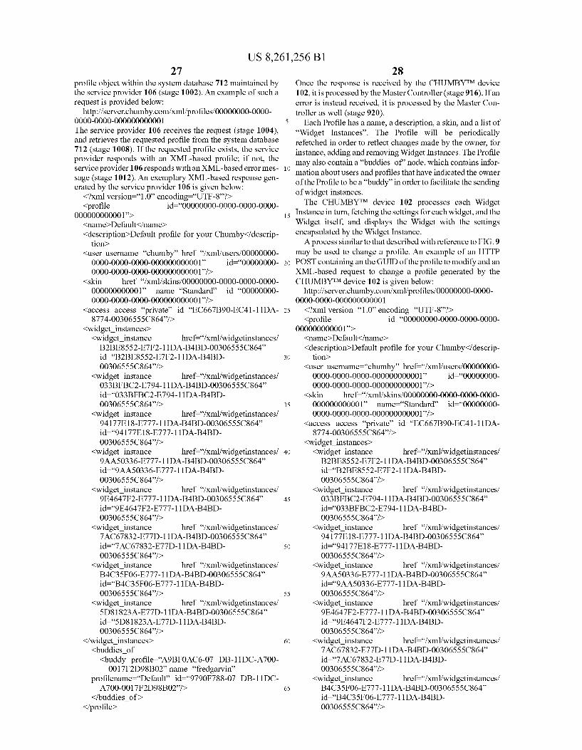
US 8,261,256 B1 27
profile object within the system database 712 maintained by the service provider 106 (stage 1002). An example of such a request is provided below:
http://server.chumby.com/xml/profiles/00000000-0000 OOOO-OOOO-OOOOOOOOOOO1 The service provider 106 receives the request (stage 1004), and retrieves the requested profile from the system database 712 (stage 1008). If the requested profile exists, the service provider responds with an XML-based profile; if not, the service provider 106 responds with an XML-based error mes sage (stage 1012). An exemplary XML-based response gen erated by the service provider 106 is given below:
<?xml version="1.0 encoding “UTF-8”?) <profile id=OOOOOOOO-OOOO-OOOO-OOOO
OOOOOOOOOOO1> <name>Default-/name> <description>Default profile for your Chumby</descrip
tion> <user username="chumby” href="/xml/users/00000000
OOOO-OOOO-OOOO-OOOOOOOOOOO1 id=OOOOOOOO OOOO-OOOO-OOOO-OOOOOOOOOOO1/>
<skin href="/xmlfskinS/00000000-0000-0000-0000 OOOOOOOOOOO1 name="Standard id="00000000 OOOO-OOOO-OOOO-OOOOOOOOOOO1/>
<access access="private” id="EC667B90-EC41-11DA 8774-00306555C864/>
<widget instances <widget instance href="/xml/widgetinstances/ B2BE8552-ETF2-11DA-B4BD-OO306555C864 id=B2BE8552-ETF2-11DA-B4BD OO306555C864/>
<widget instance href="/xml/widgetinstances/ O33BFBC2-ET94-11DA-B4BD-OO306555C864 id=O33BFBC2-ET94-11DA-B4BD OO306555C864/>
<widget instance href="/xml/widgetinstances/ 94177E18-E777-11DA-B4BD-OO306555C864 id=94177E18-E777-11DA-B4BD OO306555C864/>
<widget instance href="/xml/widgetinstances/ 9 AA50336-E777-11DA-B4BD-OO306555C864 id=9 AA50336-E777-11DA-B4BD OO306555C864/>
<widget instance href="/xml/widgetinstances/ 9E4647F2-ET77-11DA-B4BD-OO306555C864 id=9E4647F2-ET 77-11DA-B4BD OO306555C864/>
<widget instance href="/xml/widgetinstances/ 7AC67832-ETTD-11DA-B4BD-OO306555C864 id=7AC67832-ET 7D-11DA-B4BD OO306555C864/>
<widget instance href="/xml/widgetinstances/ B4C35FO6-E777-11DA-B4BD-OO306555C864 id=B4C35FO6-E777-11DA-B4BD OO306555C864/>
<widget instance href="/xml/widgetinstances/ 5D81823A-E77D-11DA-B4BD-OO306555C864 id=5D81823A-E77D-11DA-B4BD OO306555C864/>
</widget instances <buddies of <buddy profile="A9BFOAC6-07 DB-11DC-A700
001.7F2D98B02” name="fredgarvin' profilename="Default” id="9790F788-07 DB-11DC A700-0017F2D98BO2/>
</buddies of > </profile>
10
15
25
30
35
40
45
50
55
60
65
28 Once the response is received by the CHUMBYTM device 102, it is processed by the Master Controller (stage 916). Ifan error is instead received, it is processed by the Master Con troller as well (stage 920).
Each Profile has a name, a description, a skin, and a list of “Widget Instances”. The Profile will be periodically refetched in order to reflect changes made by the owner, for instance, adding and removing Widget Instances. The Profile may also contain a “buddies of node, which contains infor mation about users and profiles that have indicated the owner of the Profile to be a “buddy” in order to facilitate the sending of widget instances. The CHUMBYTM device 102 processes each Widget
Instance in turn, fetching the settings for each widget, and the Widget itself, and displays the Widget with the settings encapsulated by the Widget Instance. A process similar to that described with reference to FIG.9
may be used to change a profile. An example of an HTTP POST containing an the GUID of the profile to modify and an XML-based request to change a profile generated by the CHUMBYTM device 102 is given below:
http://server.chumby.com/xml/profiles/00000000-0000 OOOO-OOOO-OOOOOOOOOOO1 <?xml version="1.0 encoding “UTF-8”?) <profile id=OOOOOOOO-OOOO-OOOO-OOOO
OOOOOOOOOOO1> <name>Default-/name> <description>Default profile for your Chumby</descrip
tion> <user username="chumby” href="/xml/users/00000000
OOOO-OOOO-OOOO-OOOOOOOOOOO1 id="OOOOOOOO OOOO-OOOO-OOOO-OOOOOOOOOOO1/>
<skin href="/xml/skinS/00000000-0000-0000-0000 OOOOOOOOOOO1 name="Standard id="00000000 OOOO-OOOO-OOOO-OOOOOOOOOOO1/>
<access access="private” id="EC667B90-EC41-11DA 8774-00306555C864/>
<widget instances <widget instance href="/xml/widgetinstances/ B2BE8552-ETF2-11DA-B4BD-OO306555C864 id=B2BE8552-ETF2-11DA-B4BD OO306555C864/>
<widget instance href="/xml/widgetinstances/ O33BFBC2-ET94-11DA-B4BD-OO306555C864 id=O33BFBC2-ET94-11DA-B4BD OO306555C864/>
<widget instance href="/xml/widgetinstances/ 94177E18-E777-11DA-B4BD-OO306555C864 id=94177E18-E777-11DA-B4BD OO306555C864/>
<widget instance href="/xml/widgetinstances/ 9 AA50336-E777-11DA-B4BD-OO306555C864 id=9AASO336-E777-11DA-B4BD OO306555C864/>
<widget instance href="/xml/widgetinstances/ 9E4647F2-ET 77-11DA-B4BD-OO306555C864 id=9E4647F2-ET 77-11DA-B4BD OO306555C864/>
<widget instance href="/xml/widgetinstances/ 7AC67832-ETTD-11DA-B4BD-OO306555C864 id=7AC67832-ET 7D-11DA-B4BD OO306555C864/>
<widget instance href="/xml/widgetinstances/ B4C35FO6-E777-11DA-B4BD-OO306555C864 id=B4C35FO6-E777-11DA-B4BD OO306555C864/>

US 8,261,256 B1 29
<widget instance href="/xml/widgetinstances/ 1OA66395-85OO-215E-81 FO-OO3256F982.57 id=1OA66395-85OO-215E-81 FO-003256F98257/>
</widget instances </profile>
An exemplary XML-based response corresponding to such a request which contains the updated profile could be provided by the service provider 106 as follows:
<?xml version="1.0 encoding “UTF-8”?) <profile id=OOOOOOOO-OOOO-OOOO-OOOO
OOOOOOOOOOO1> <name>Default-/name> <description>Default profile for your Chumby</descrip
tion> <user username="chumby” href="/xml/users/00000000
OOOO-OOOO-OOOO-OOOOOOOOOOO1 id=OOOOOOOO OOOO-OOOO-OOOO-OOOOOOOOOOO1/>
<skin href="/xmlfskinS/00000000-0000-0000-0000 OOOOOOOOOOO1 name="Standard id="00000000 OOOO-OOOO-OOOO-OOOOOOOOOOO1/>
<access access="private” id="EC667B90-EC41-11DA 8774-00306555C864/>
<widget instances <widget instance href="/xml/widgetinstances/ B2BE8552-ETF2-11DA-B4BD-OO306555C864 id=B2BE8552-ETF2-11DA-B4BD OO306555C864/>
<widget instance href="/xml/widgetinstances/ O33BFBC2-ET94-11DA-B4BD-OO306555C864 id=O33BFBC2-ET94-11DA-B4BD OO306555C864/>
<widget instance href="/xml/widgetinstances/ 94177E18-E777-11DA-B4BD-OO306555C864 id=94177E18-E777-11DA-B4BD OO306555C864/>
<widget instance href="/xml/widgetinstances/ 9 AA50336-E777-11DA-B4BD-OO306555C864 id=9 AA50336-E777-11DA-B4BD OO306555C864/>
<widget instance href="/xml/widgetinstances/ 9E4647F2-ET77-11DA-B4BD-OO306555C864 id=9E4647F2-ET 77-11DA-B4BD OO3065550.864/>
<widget instance href="/xml/widgetinstances/ 7AC67832-ETTD-11DA-B4BD-OO306555C864 id=7AC67832-ET 7D-11DA-B4BD OO306555C864/>
<widget instance href="/xml/widgetinstances/ B4C35FO6-E777-11DA-B4BD-OO306555C864 id=B4C35FO6-E777-11DA-B4BD OO306555C864/>
<widget instance href="/xml/widgetinstances/ 1OA66395-85OO-215E-81 FO-OO3256F982.57 id=1OA66395-85OO-215E-81 FO-003256F98257/>
</widget instances </profile> Widget Instance Upload/Download Turning now to FIGS. 11-12, there are shown signal flow
diagrams representative of the communication of widget instance information from the CHUMBYTM device 102 to the service provider 106, and vice-versa. In one embodiment the set of parameters associated with a widget instance determine the user-specified manner in which the behavior of the widget is modified when executed by a CHUMBYTM device 102. That is, the parameters fetched by the CHUMBYTM device 102 from the service provider 106 for a given widget consti tute the user's "customized settings, rather than dynamic
10
15
25
30
35
40
45
50
55
60
65
30 content. For example, in the case of a “stock ticker widget the applicable parameters could comprise the names and symbols of the stocks within the user's portfolios, but would not define or relate to the current prices of the stocks (which would be furnished by another service supplied by the service provider 106).
FIG. 11 is a signal flow diagram which depicts processing of changes made to the parameters of a widget instance through the interface of the CHUMBYTM device 102 in which the widget is instantiated. Examples of parameter changes could include changing a location of interest in the case of a “weather widget, or adding/removing Stock ticker symbols in the case of a “stock market' widget. In the exemplary embodiment it is not necessary for the user to set or otherwise modify all parameters of a given widget, and the service provider 106 will effectively “expand the parameter change data into a full parameter record once received. For instance, a Zip code could be sufficient to uniquely identify a location in the case of a weatherwidget, and the associated city, State, etc. could be supplied to the applicable record during processing of the parameter change request by the service provider 106. As shown, the widget instance change operation is initiated
when the CHUMBYTM device 102 sends an HTTP POST and an XML request to a widget instance object within the system database 712 maintained by the service provider 106 (stage 1102). This type of “UPLOAD operation informs the service 106 that the parameters of a specific widget instance have been updated by the applicable user. As shown, the updated parameters are received by the service provider (stage 1104), and are attempted to be written to a corresponding widget instance object within the system database 712 (stage 1108). If this attempted write operation is unsuccessful (stage 1112), the service provider 106 responds with an error message that is processed by the requesting CHUMBYTM device 102 (stage 1120). If the write operation is successful, the newly updated widget instance are retrieved from the system data base 712 (stage 1116) and sent to the applicable CHUMBYTM device 102 (stage 1120). Once received, the widget instance is processed by the
CHUMBYTM device 102 (stage 1124). In general, the pro cessing of the parameters contained in a widget instance are dependent upon the characteristics of the particular widget. In certain cases the parameters may be sufficient to enable the widget to display information, while other widgets may use the parameters to fetch content from another service. As an example of the former, consider a "clock' widget capable of displaying information following receipt of a parameter indi cating a time Zone. In contrast, a “stock widget may have stock symbols as parameters and use such symbols to fetch quote information.
Referring now to FIG. 12, there is shown a signal flow diagram illustrating an exemplary widget instance download operation in which the service provider 106 is requested to push values of widget-specific parameters to a requesting CHUMBYTM device 102. The requesting of a parameter download is initiated when the CHUMBYTM device 102 sends an HTTP GET containing the GUID of the requested widget instance request to a parameter object within the sys tem database 712 maintained by the service provider 106 (stage 1202). An example of Such a request in the case of a “weather widget is provided below:
http://server.chumby.com/xml/widgetinstances/ 5D81823A-E77D-11DA-B4BD-OO306555C864 The service provider 106 receives the request (stage 1204), and retrieves the requested parameters from the system data base 712 (stage 1208). If the requested parameters exist, the service provider 106 responds with an XML-based widget
US 8,261,256 B1 31
instance message (stage 1212). Using the example of a weather widget, which utilizes a zip code to identify the location for which weather is to be retrieved, such a message could comprise:
<?xml version="1.0 encoding “UTF-8”?) 5 <widget instance id="5D81823A-E77D-11DA-B4BD
OO306555C864's <widget href="/xml/widgets/BF4CE814-DFB8-11DA
9C82-OO306555C864 id=BF4CE814-DFB8-11DA 9C82-OO306555C864/>
<profile href="/xml/profiles/00000000-0000-0000-0000 OOOOOOOOOOO1 id=OOOOOOOO-OOOO-OOOO-OOOO OOOOOOOOOOO1/>
<access access="private/> <mode time='10' mode="timeout/> <received buddy=“9790F788-07 DB-11DC-A700
001.7F2D98B02” forward=“true” accepted=“false"/> <widget parameters>
<widget parameter id="BF4CE814-DFB8-11DA- 20 9C82-OO3O6643C864’s <name>ZipCode</name> <value-92037.</name>
</widget parameters </widget parameters> 25 </widget instances The CHUMBYTM device 102 uses the GUID in the “Wid
get tag to fetch the information about the Widget to be displayed. Once the widget has been started, it is passed the name/value pairs in the “widget parameters' section, in order 30 to customize the behavior of the widget. The “mode' tag indicates how long the widget is to be played. A value of “default' in the mode attribute indicates that the timing will be specified by the widget description, an attribute value of “timeout' will use the duration specified in the “time' 35 attribute (in seconds), and the value of “cooperative' will display the widget until the user explicitly commands it to stop through a UI element, or the widget itself indicates that it wishes to discontinue operation. The presence of a “received node indicates that the widget instance has been 40 “sent by a buddy. The value of the “accepted' attribute indicates whether or not the widget instance has been accepted by the recipient, which is done either through the web interface or through the UI of the device. The “forward attribute indicates whether this widget instance can be sent on 45 to another user.
If the requested parameters do not exist, a default widget instance is attempted to be retrieved from the system database 712 (stage 1224). If Such a widget instance exists (stage 1228), the service provider 106 responds with an XML-based 50 parameters message that is processed by the CHUMBYTM device 102 upon receipt (stage 1220). If such a default widget instance does not exist, an error message is returned to the CHUMBYTM device 102 (stage 1232).
Downloading a Widget 55 Referring now to FIG. 27, a signal flow diagram 2700 is
provided which illustratively represents the process of down loading the code for a widget (e.g., a .swf file) from the service provider 106 for execution on a CHUMBYTM device 102. The process is initiated when the CHUMBYTM device 60 102 sends an HTTP GET request containing the GUID of the requested widget to a specific widget description object within the system database 712 maintained by the service provider 106 (stage 1302). An example of such a request is provided below: 65
http://server.chumby.com/xml/widgets/BF4CE814 DFB8-11DA-9C82-00306555C864
10
15
32 The service provider 106 receives the request (stage 2704),
and attempts to retrieve the requested widget description from the system database 712 or other data source available to the service provider 106 (stage 2708). If the requested widget description is able to be retrieved, the service provider 106 responds with an XML-based widget description message; if not, the service provider 106 responds with an XML-based error message (stage 2712). An exemplary XML-based response generated by the service provider 106 is given below: <?xml version="1.0 encoding “UTF-8”?) <widget id="BF4CE814-DFB8-11DA-9C82
OO306555C864's <name>Time Zones</name> <description>A time Zone selectors/description> <version>1.0</version> <protection protection="none'/> <mode time='15' mode='default/> KaCCeSS Sendable="true' deleteable="true'
access="public” virtualable="true”/> <user username="chumby” href="/xml/users/00000000
OOOO-OOOO-OOOO-OOOOOOOOOOO1 id=OOOOOOOO OOOO-OOOO-OOOO-OOOOOOOOOOO1/>
<category href="/xml/categories/00000000-0000-0000 OOOO-OOOOOOOOOOO1 name="Chumby' id=OOOOOOOO-OOOO-OOOO-OOOO-OOOOOOOOOOO1
<thumbnail content type="image/jpeg href="/xml/ thumbnails/BF4CE814-DFB8-11DA-9C82 OO306555C864/>
<template content type="text/xml href="/xml/templates/ BF4CE814-DFB8-11DA-9C82-00306555C864/>
<movie content type="application/x-shockwave-flash” href="/xml/movieS/BF4CE814-DFB8-11DA-9C82 OO306555C864/>
<rating count=“0” rating="0.0/> </widget Once the requested widget description is received by the
CHUMBYTM device 102, the CHUMBYTM device 102 uses the URL referencing the “movie' for the requested widget to download the movie (e.g., .swf) file from the service provider 106. The CHUMBYTM device 102 sends an HTTP GET request containing the GUID of the requested movie to a specific movie object within the system database 712 main tained by the service provider 106 (stage 1320). An example of such a request is provided below:
http://server.chumby.com/xml/movies/BF4CE814 DFB8-11DA-9C82-OO306555C864 The service provider 106 receives the request (stage 2724),
and attempts to retrieve the requested movie from the system database 712 or other data source available to the service provider 106 (stage 2728). If the requested movie is able to be retrieved, the service provider 106 responds with the .swf file which implements the movie; if not, the service provider 106 responds with an XML-based error message (stage 2732). Once the requested movie is received by the CHUMBYTM device 102, it is loaded by the Master Controller and queued for subsequent execution (stage 2736). If an error is instead received, it is processed accordingly (stage 2740).
Requesting Content Referring now to FIG. 13, a signal flow diagram 1300 is
provided which illustratively represents the process of obtain ing content from the service provider 106 for a widget of a CHUMBYTM device 102. The process is initiated when the CHUMBYTM device 102 sends an HTTP GET and an optional XML request to a specific content object within the system database 712 maintained by the service provider 106

US 8,261,256 B1 33
(stage 1302). An example of Such a request for content for a “tide' widget is provided below:
http://content.chumby.com/tides/United%20States/ National%20City%2C9%20San%20Diego%20Bay%2C9620Californiaide
The service provider 106 receives the request (stage 1304), and attempts to retrieve the requested content from the system database 712, internal content service, external content ser vice or other data source available to the service provider 106 (stage 1308). If the requested content is able to be retrieved, the service provider 106 responds with an XML-based con tent message; if not, the service provider 106 responds with an XML-based error message (stage 1312). Once the requested contentis received by the CHUMBYTM device 102, corresponding audiovisual output is generated by the device 102 for the benefit of its user (stage 1316). If an error is instead received, it is processed accordingly (stage 1320). An exemplary XML-based response generated by the service provider 106 is given below:
<tideitems> <tideitem timestamp="2006-05-31T00:39:11Z'>
<location> <locationstring string “National City, San Diego
Bay, California'/> <station id="National City, San Diego Bay/> <state name="California'/> <country name="United States"/> M <coordinates lat=“32.6667A N, lon=“117.1167A W/>
</location> <tides>
<tide dateTime="2006-05-31T 12:44:00Z, tidedescription="Low Tide', tidelevel="0.85 meters/>
<tide dateTime="2006-05-31T02:50:00Z, tidedescription="Sunset/>
<tide dateTime="2006-05-31T06:30:00Z, tidedescription="Moonset/>
<tide dateTime="2006-05-31T06:56:00Z, tidedescription="High Tide', tidelevel="1.80 meters/>
<tide dateTime="2006-05-31T24:41:00Z, tidedescription="Sunrise/>
<tide dateTime="2006-05-31T 14:46:00Z, tidedescription="Low Tide', tidelevel="-0.13 meters/>
<tide dateTime="2006-05-31T 16:38:00Z, tidedescription="Moonrise/>
<tide dateTime="2006-05-31T21:55:00Z, tidedescription="High Tide', tidelevel="1.14 meters/>
<tide dateTime="2006-06-01TO1:38:00Z, tidedescription="Low Tide', tidelevel="0.92 meters/>
<tide dateTime="2006-06-01 TO2:50:00Z, tidedescription="Sunset/>
<tide dateTime="2006-06-01T07:06:00Z, tidedescription="Moonset/>
<tide dateTime="2006-06-01T07:41:00Z, tidedescription="High Tide', tidelevel="1.64 meters/>
<tide dateTime="2006-06-01 124:41:00Z, tidedescription="Sunrise/>
<tide dateTime="2006-06-01T15:37:00Z, tidedescription="Low Tide', tidelevel="-0.01 meters/>
<tide dateTime="2006-06-01T 17:38:00Z, tidedescription="Moonrise/>
5
10
15
25
30
35
40
45
50
55
60
65
34 <tide dateTime="2006-06-01T22:59:00Z,
tidedescription="High Tide', tidelevel="1.18 meters/>
dateTime="2006-06-02TO2:51:00Z, tidedescription="Sunset/>
<tide dateTime="2006-06-02TO2:58:00Z, tidedescription="Low Tide', tidelevel="0.96 meters/>
<tide dateTime="2006-06-02TO7:37:00Z, tidedescription="Moonset/>
<tide dateTime="2006-06-02T08:35:00Z, tidedescription="High Tide', tidelevel="1.47 meters/>
<tide dateTime="2006-06-02T24:41:00Z, tidedescription="Sunrise'/>
<tide dateTime="2006-06-02T16:28:00Z, tidedescription="Low Tide', tidelevel="0.09 meters/>
<tide dateTime="2006-06-02T18:35:00Z, tidedescription="Moonrise/>
<tide dateTime="2006-06-02T23:51:00Z, tidedescription="High Tide', tidelevel="1.26 meters/>
<tide dateTime="2006-06-03TO2:51:00Z, tidedescription="Sunset/>
<tide dateTime=2006-06-03T04:44:00E, tidedescription="Low Tide', tidelevel="0.93 meters/>
<tide dateTime="2006-06-03T08:04:00Z, tidedescription="Moonset/>
<tide dateTime="2006-06-03T09:46:00Z, tidedescription="High Tide', tidelevel="1.31 meters/>
<tide dateTime="2006-06-03T24:41:00Z, tidedescription="Sunrise'/>
<tide dateTime="2006-06-03T17:17:00Z, tidedescription="Low Tide', tidelevel="0.19 meters/>
<tide dateTime="2006-06-03T19:31:00Z, tidedescription="Moonrise/>
<tide dateTime="2006-06-03T23:06:00Z, tidedescription="First Quarter/>
<tide dateTime="2006-06-04T12:30:00Z, tidedescription="High Tide', tidelevel="1.35 meters/>
</tides> </tideitems </tideitems> In the case where content is retrieved directly from an
external content service provider (i.e., from other than the service provider 106), a series of web-based transactions (most likely HTTP and/or XML-based) defined by such con tent service provider will take place between the CHUMBYTM device 102 and such provider.
CHUMBYTM Security Protocol
CHUMBYTM devices 102 may optionally include a hard ware security module, which in one implementation is accessed via a character driver interface in the operating system (“OS) of the device 102. The module may or may not be installed. When the module is not installed, the OS pref erably virtualizes the hardware security module by emulating it in software. While losing all the tamper-resistance benefits of a hardware module, this feature enables cost reduction savings while maintaining protocol interoperability with a secured system.
US 8,261,256 B1 35
The hardware security module of a CHUMBYTM device 102 may be implemented in a number of ways. As an example, the hardware security module may be implemented using a monolithic security processor or a cryptographic Smart Card module. This module, or its emulated counter part, is capable of at a minimum, the following operations: (1) storage of secret numbers in hardware; (2) the ability to compute public-key signatures; (3) the ability to compute one-way cryptographic hashes; and (4) the ability to generate trusted random numbers.
During the manufacturing process the hardware security module, or its emulated counterpart, is initialized with a set of secret numbers that are only known to the module and to the CHUMBYTM service provider 106. These secret numbers may or may not consist of public and private keys. If the numbers consist of public and private keys, then a mutual key-pair is stored by both the CHUMBYTM service provider 106 and the hardware module, along with a putative, insecure identifier number for the pair. Furthermore, these numbers are preferably not recorded by the CHUMBYTM service provider 106 in association with any other identifying information, such as the MAC address for the WLAN interface, or any other serial numbers that are stored in insecure memory for customer service purposes. When the user or service wishes to initiate a strong authen
ticated transaction, the CHUMBYTM device 102 sends the putative insecure key-pair identifier to the service provider 106. The service provider 106 looks up the putative insecure key-pair identifier and issues a challenge to the hardware module, consisting of a random number In particular, the challenge is packetized and sent through the Internet to the CHUMBYTM device 102. The device 102 unpacks the chal lenge and passes it directly to the hardware module. The hardware module adds another random number to the packet and signs the pair of numbers, along with other transaction information (such as the version number of the protocol) with a private key that is only known to the CHUMBY cryptopro cessor. In addition, an 'owner key may optionally be encrypted to the server public key. Again, this message is packetized and transmitted by the device 102 to the service provider 106 over the Internet. Upon receipt, the service provider 106 verifies the signature of the packet using the device's public key, which was generated and recorded at the time of manufacture and indexed by the hash of the putative insecure key-pair identifier. The CHUMBY device is deemed authentic if the signature is correct and the signed packet contains the exact random number that was generated by the service provider in the first step of the challenge. The service provide 106 also decrypts the owner key, whose purpose is discussed in the next paragraph. At the conclusion of this transaction, the service provider 106 has authenticated the device 102, and can fall back to any number of session keys that can be either dynamically generated or statically stored for further secured transactions. Advantageously, this authen tication transaction does not involve uniquely associating the hardware module with user information. Rather, the service provider 106 is simply aware of the existence of the approved hardware module and upon completion of the authentication transaction may safely trust the integrity of the secrets stored therein.
The owner key comprises a random number (or one of a set of random numbers) generated at the time of manufacture and stored only within the cryptographic processor. The owner key is transmitted to the server, encrypted using the server public key, and used as a shared secret to protect any other secrets (user passwords, credit card information, etc.) that may be stored on the server. Once a user decides they no
10
15
25
30
35
40
45
50
55
60
65
36 longer wish to continue with the service, or desire to sell or transfer their CHUMBYTM device, or otherwise wish to revoke any secrets entrusted to the server, the user can instruct the cryptographic processor to delete the key from memory, thereby abolishing the server's ability to decrypt the secrets entrusted to it. A user of the device 102 may opt-out of privacy mode and
provide identifying information, as required by some billing services Such as credit cards and banks. Optionally, an anony mous cash-based transaction network can be established where accounts are opened and managed only by secrets contained within the hardware module. To enable limited revocation of user-identifying informa
tion, the specific embodiment of the master authentication protocol should operate on a set of clean-room servers with a multiplicity of connections that are trusted by the CHUMBYTM service provider 106, and authenticated session keys are then passed on laterally to the content servers. Thus, the anonymity of the master authentication key is nominally preserved, although it is possible to recreate and correlate transactions from forensic logs and transaction timings. The use of multiple servers and multiple connections, along with network routing randomization techniques, can be used to increase the anonymization resistance to forensic logging (cf. Tor network), but this configuration is in no way essential to the network's operation.
CHUMBYTM Device Calibration, Registration and Account Management
Attention is now directed to FIGS. 14-21, which area set of flowcharts representative of the calibration, registration and initial operation of a CHUMBYTM device and associated account management functions.
Initial Power-Up FIG. 14 is a flowchart 1400 which depicts an exemplary
sequence of operations performed by a CHUMBYTM device 102 upon initial power-up. When a user initially connects a CHUMBYTM device 102 to a power source, the device 102 undergoes a touchscreen calibration process described below with reference to FIGS. 15-16 (stage 1404). The device 102 then selects a wireless base station in the manner described below with reference to FIG. 17 (stage 1408). If a proxy server is identified (stage 1412), then information relating to the proxy server is configured into the CHUMBYTM device 102 to enable it to with the Web site maintained by the service provider 106 (as well as with the Web sites of content provid ers) (stage 1416). At this point the user of the CHUMBYTM device 102 is prompted to set the time Zone in which the device 102 is located (stage 1420). If an NTP server is deter mined to be available (stage 1430), then time is set automati cally based upon information acquired from Such a server (stage 1440). If not, the CHUMBYTM device 102 is refer enced to a time set manually (stage 1444). After the time of the CHUMBYTM device 102 has been set, the registration process described below with reference to FIG. 18 is initiated (stage 1450).
In one embodiment a CHUMBYTM device downloads con figuration information from the service provider 106 each time it is powered on or otherwise re-establishes communi cation with the service provider 106. However, a minimal amount of widget and configuration information may be locally stored on a CHUMBYTM device so that it may con tinue to function in the absence of network connectivity. For example, a clock widget may be permanently stored on a CHUMBYTM device so that its clock function could remain operational at all times. A CHUMBYTM device will typically

US 8,261,256 B1 37
include Sufficient memory capacity to hold configuration information received from the service provider 106 for all of the widgets to be executed by the device, up to some reason able number of widgets. If a user changes the configuration for a CHUMBYTM device through the Web site maintained by the service provider 106, a polling function implemented on the corresponding CHUMBYTM device will typically be used to “pull the modified configuration information from the service provider 106. Alternatively, an operation may be manually initiated via the interface of the corresponding CHUMBYTM device in order to obtain this information (e.g., an “Update My CHUMBYTM Device Now” operation).
Touchscreen Calibration Turning now to FIG. 15, there is shown a flowchart which
illustrates an exemplary routine used to calibrate the touch screenofa CHUMBYTM device 102. FIGS. 16A-16E provide a set of Screen shots of the user interface of the CHUMBYTM device 102 being calibrated pursuant to the routine of FIG. 15. As shown, the calibration routine involves determining an upper left set point (stage 1502). This set point is determined by generating a target 1602 (FIG. 16A) through the LCD screen 320 which the user is then prompted to tap. A lower right set point is then determined by prompting the user to tap a target 1604 depicted in FIG. 16D (stage 1506). After the lower right set point target 1604 has been tapped, the user is instructed to test the touch screen calibration (stage 1510) by dragging the ball 1605 depicted in FIG.16C from ring A 1606 to ring B 1607. Once the ball 1605 has been successfully placed in ring B 1607, a notification of success 1608 as depicted in FIG. 16D will be displayed and done button 1609 will be activated. Once the done button 1609 has been pressed, the results of the calibration process are then stored (stage 1514). Based upon the coordinate data received from the touchscreen 330 during each of stages 1502 and 1506, the CPU 302 executes a program to generate calibration infor mation used during Subsequent operation of the device 102.
Wireless Base Station Selection FIG. 17 is a flowchart illustrating the operations performed
in selecting a wireless base station upon initial power-up of the device 102. As shown, the Wi-Fi communications inter face 314 of the device initially searches for one or more access points 210 emitting a beacon signal (stage 1702). If the device is configured to search for access points not emitting a beacon signal (stage 1706), then a keyboard is accessed (stage 1710) and data designating an access point is entered (stage 1714). The keyboard may comprise a physical keyboard connected to the device 102 as a peripheral component. Alternatively, an “onscreen” keyboard generated by the LCD screen 320 and interacted with via the touchscreen 330 may be utilized. Once data designating an access point has been entered, a Subse quent scan (stage 1715) will be initiated in an attempt to find the access point that was not emitting a beacon signal. Once one or more wireless networks have been discovered, the user is given the option to select one from a list (stage 1717). When a wireless network is selected, the CPU 302 executes a pro gram to determine various aspects of the chosen wireless network (stage 1718), including but not limited to authenti cation mode, encryption type, channel/frequency, etc. If a suitable network is not detected, the user may be given the choice to enter the network configuration properties (e.g. SSID, authentication mode, etc) manually (stage 1730). If the user chooses to manually enter network properties, a key board (stage 1710) is displayed and the user is prompted to enter the network properties (stage 1731). If the selected or designated network requires authentication (e.g., WPA, WPA2, etc) and/ororis otherwise encrypted (e.g., WEP, AES, TKIP, etc), a keyboard (stage 1710) is displayed and the user
10
15
25
30
35
40
45
50
55
60
65
38 is given the opportunity to enter the applicable key (stage 1720). In the event that a user enters a WEP key, the key size will be determined automatically by the length of the key entered by the user. The user is then presented with a choice of automatic or manual IP allocation (stage 1732). Should the user select a manual IP allocation, a keyboard (stage 1710) is displayed and the user is prompted to enter IP related con figuration data (stage 1733) such as IP address, netmask, gateway, nameservers, etc. After the IP allocation method has been chosen and optionally configured, the user will be asked to confirm the network settings (stage 1735). A connection is then attempted to be established with a detected or designated access point (stage 1740). If a connection is so established (stage 1750), then the information relating to the connection is stored within the memory of the device 102 (stage 1755); otherwise the user is given the option to reattempt to establish the connection.
Registration Referring now to FIG. 18, a flowchart is provided of an
exemplary account creation and registration process 1450. The process begins upon presentation by the device, via its LCD screen 320, of its serial number or other identifying information (stage 1802). The user then logs in, via a Web browser 122, to a web site operated by the service provider 106 (e.g., www.chumby.com) (stage 1804). In one embodi ment the user may then select a “create new user account” tab or the like (stage 1808), and is prompted to enter an email address (stage 1810), password (stage 1812), and name (stage 1816). In certain implementations the user may also be offered the opportunity to enter his or her address (stage 1820), while in other implementations the user is not prompted to provide an address until this information is required for Some particular purpose (e.g., to provide a billing information for a subscription or shipping information for a product purchase). If this option is selected, the user enters his or her address (stage 1824). In certain implementations, the user may be prompted to provide other identifying and/or demographic information (not shown in this figure). At this point the service provider 106 sends an email to the address entered in stage 1810 which contains a "click through” account activation hyperlink (stage 1830). If the user does not receive this message (stage 1834), the user is provided with the opportunity to take advantage of various customer service options in order to remedy the account creation difficulties being experienced (stages 1840-1841). In any event, the account creation process is then finalized (stage 1850), and the CHUMBYTM device being registered is associated within the system database 712 with a particular user account in the manner described below (stage 1854). Once this has occurred a default configuration and a number of widget instances are established for the newly registered CHUMBYTM device (stage 1860). Account Association FIG. 19 is a flowchart representative of exemplary Web
based interaction occurring between a user and the service provider 106 in connection with associating a particular CHUMBYTM device with the user's account. The process is initiated when the user logs in to a Web site operated by the service provider 106 (stage 1902) and selects an Activate a CHUMBYTM” link or the equivalent (stage 1904). The user enters a name of the CHUMBYTM device (e.g., bedroom, study, Fred, evening, etc.) (stage 1908) and then, as described in the above-referenced U.S. Provisional Application Ser. No. 60/945,900, the user duplicates the “captcha grid” pattern displayed on the “Activate a CHUMBYTM page on the cor responding “Activate CHUMBYTM” screen on the CHUMBYTM device and selects “OK” (stage 1910). The

US 8,261,256 B1 39
CHUMBYTM device then transmits the encoded pattern along with the putative id (unique serial number) of the CHUMBYTM device to the server for verification and asso ciation with the user's account. Alternatively, the user may directly enter the putative id (unique serial number) of the user's CHUMBYTM device into the Web page and selects “OK” (stage 1910). An association is then created between the user’s CHUMBYTM device and the applicable account within the system database 712.
In one embodiment user accounts are configured to be capable of hosting and moderating Sub-accounts.
Disabling a CHUMBYTM Device Referring now to FIG. 20, a flowchart is provided of exem
plary Web-based interaction occurring between a user and the service provider 106 with regard to disabling a CHUMBYTM device that has been previously associated with the user's account. As shown, the user logs in to the account via a Web browser 122 (stage 2002) and selects a “Disable CHUMBYTM device” tab or the equivalent (stage 2004). The user then selects the CHUMBYTM device to be disabled from a list based upon either the device's serial number or descrip tion (stage 2006). Next the user is prompted to confirm the selection (stage 2010), and if so all references to the disabled CHUMBYTM device are removed from the directory main tained within the system database 712 (stage 2014). The process is then completed whether or not the selection is confirmed (stage 2020), at which point the service provider 106 no longer responds to requests from the CHUMBYTM device which has been disabled.
Mirroring a CHUMBYTM Device FIG. 21 is a flowchart which represents exemplary Web
based interaction occurring between a user and the service provider 106 in connection with “mirroring CHUMBYTM devices; that is, enabling one CHUMBYTM device to utilize the widget set and configuration of another CHUMBYTM device. In one embodiment once a given CHUMBYTM device (i.e., the “slave device’) has been mirrored to another CHUMBYTM device (i.e., the “master device'), widget-re lated changes made to the master device are automatically reflected in the slave device. As shown in FIG. 21, the user logs into the applicable account via a Web browser 122 (stage 2102) and selects a “Mirror this CHUMBYTM device” tab or the equivalent (stage 2104). The user then selects the CHUMBYTM device to be the “master” (stage 2108) and further selects the CHUMBYTM device to the “slave” (stage 2112). In certain embodiments the master CHUMBYTM device need not correspond to a physical device, but could instead constitute a “virtual CHUMBYTM device defined within the system database 712. In this case changes made to the widget set or configuration of the virtual CHUMBYTM device would be mirrored by all of its slave CHUMBYTM devices. In certain embodiments the slave CHUMBYTM device need not correspond to a physical device, but could instead constitute a “virtual CHUMBYTM device defined within the system database 712.
Widget Selection, Removal and Configuration
Attention is now directed to FIGS. 22-25,37 and 38, which are a set of flowcharts representative of Web-based widget selection, removal and configuration processes contemplated by embodiments of the present invention. Screen shots of exemplary user interfaces presented by the Web browser 122 or, alternatively, the screen 320 of the applicable CHUMBYTM personal audiovisual device 102, which are used to facilitate certain of these processes are illustrated in FIG. 26.
10
15
25
30
35
40
45
50
55
60
65
40 Overview of Widget Management Process Turning now to FIG. 22, a top-level flowchart 2200 is
provided of exemplary Web-based interaction occurring between a device user and the service provider 106 with regard to adding, removing and configuring widget profiles relative to the user's CHUMBYTM device. Alternatively, this interaction between a device user and the service provider 106 may be effected through user interface screens presented by the user’s CHUMBYTM device in lieu of the Web browser 122. Although a user may have the impression that a CHUMBYTM device itself is being configured through the process of FIG. 22, in the exemplary embodiment a profile currently assigned to the user's CHUMBYTM device is instead configured. As shown in FIG. 22, the user logs into the user's account
maintained with the service provider 106 via a Web browser 122 (stage 2202) and proceeds to the user's “home page' or the equivalent (stage 2204). From this home page the user selects a “Set Up' device tab or the like (stage 2208) and the Web browser 122 presents a corresponding “Set Up' page (stage 2210). The user then selects the CHUMBYTM device profile to be configured from a list based upon either the device's serial number or description (stage 2212). The cur rent configuration for the selected device profile is then retrieved from the system database 712 and loaded into the device (stage 2216). Once this has occurred the user selects an action to be performed, as is illustrated by FIG. 26A (stage 2220). Such actions may include, for example, adding, delet ing or editing widget profiles. If the user opts to add widget profiles (stage 2224), then the Web browser 122 displays an “Add Widgets Page' through which widget profiles may be added to the current configuration of the applicable CHUMBYTM device in the manner described below with reference to FIG. 23 (stage 2228). If the user instead chooses to delete widget profiles from Such current configuration (stage 2232), then a “Delete Widgets Page' is presented through which the deletion operation may be completed con sistent with the approach described below with reference to FIG. 24 (stage 2236). Alternatively, the user may select another CHUMBYTM device profile to configure (stage 2240), or simply exit and return to the user's home page (stage 2244).
Turning now to FIG. 37, an alternate top-level flowchart 3700 is provided of exemplary Web-based interaction occur ring between a device user and the service provider 106 with regard to adding, removing and configuring widget profiles relative to the user’s CHUMBYTM device. Although a user may have the impression that a CHUMBYTM device itself is being configured through the process of FIG.37, in the exem plary embodiment a profile currently assigned to the user's CHUMBYTM device is instead configured. As shown in FIG. 37, the user logs into the user's account
maintained with the service provider 106 via a Web browser 122 (stage 3702) and proceeds to the user’s “MY CHUMBYTM page” or the equivalent, as is illustrated by FIG. 39A (stage 3704). From this MY CHUMBYTM page the user optionally selects the CHUMBYTM device to be configured from a list or the like, as is illustrated by FIG. 39B (stage 3706) and the Web browser 122 loads the currently config ured widget channel into the current page (stage 3708). The user then optionally selects the CHUMBYTM widget channel to be configured from a list or the like, as is illustrated by FIG. 39C (stage 3710). The current channel configuration for the selected CHUMBYTM device is then updated in the system database 712, loaded into the current page (stage 3712) and loaded by the currently selected CHUMBYTM device (stage 3713). At any point the user may select the “Edit Channel

US 8,261,256 B1 41
option (stage 3714), following which a “Edit Channel Page' is presented, as is illustrated by FIG. 39D (stage 3716), with the widget configuration for the selected channel is loaded into the page (stage 3718). Once this has occurred, the user may select an action to be performed (stage 3720). Such actions may include, for example, changing, renaming, delet ing or creating new widget channels; adding widgets to, removing widgets from, changing playback order of widgets within or configuring widgets within the selected channel. If the user opts to perform a widget action (stage 3724), then the widget instance for the affected widget and/or the configura tion for the selected channel within the system database 712 are updated, which Subsequently effects a corresponding update to the local copy of the channel configuration of all CHUMBYTM devices currently “playing the selected chan nel (stage 3728). If the user opts to perform a channel action (stage 3732), then the configuration for the selected channel within the system database 712 is updated which subse quently effects a corresponding update to the local copy of the channel configuration of all CHUMBYTM devices currently “playing the selected channel (stage 3734). Alternatively, the user may select another channel to configure (stage 3740), or navigate to another page (stages 3742, 3744).
Adding Widgets FIG. 23 is a flowchart 2300 representative of exemplary
Web-based interaction occurring between a device user and the service provider 106 with respect to the addition of wid gets to the current configuration of the user's CHUMBYTM device. Alternatively, this interaction between a device user and the service provider 106 may be effected through user interface screens presented by the user's CHUMBYTM device in lieu of the Web browser 122. In one embodiment the user is provided with the opportunity to choose, through an appro priate category selection page (see, e.g., FIG. 26B) presented by a Web browser 122, among various widget categories retrieved from the categories table of the system database 712 (stage 2302). After selecting a widget category (stage 2304), both the widgets included within the selected category and the current widget configuration of the applicable CHUMBYTM device are presented to the user (stage 2308). The user then selects an action to perform (stage 2312) including, for example, exiting the widget addition process (stage 2316) or navigating the list of widgets presented for the selected cat egory (stage 2320). If the latter action is selected (see, e.g., FIGS. 26C-26D), the user then selects a widget to be added to the current configuration (e.g., by selecting a corresponding icon) and the service provider 106 constructs an instance of the selected widget (stage 2324). At this point the user may also opt to add yet more widgets to the current configuration (stage 2328). Once the user has indicated that no additional widgets are to be added, a widget configuration phase (stage 2332) may be entered (see, e.g., FIG. 26E). If the user declines to select a widget while navigating the list of widgets presented for a selected category during stage 2320, a new category of widgets may be selected (stage 2340).
If the user decides to exit the process of adding widgets to the current configuration, the user may perform one of several actions, including, but not limited to: Select another CHUMBYTM device to configure; navigate to another page on the CHUMBYTM site; log out from the CHUMBYTM site: or close the applicable browser window (stage 2316). If the user instead chooses to save the current widget configuration for the applicable CHUMBYTM device (stage 2350), the user selects a “Submit”, “Commit”, “Ok” or similar button to cause any changes made to be recorded in the system database 712 (stage 2354). After either saving the current widget con
10
15
25
30
35
40
45
50
55
60
65
42 figuration or electing to exit the process, the user may be directed to a predefined page (stage 2360).
FIG. 38 is an alternate flowchart 3800 representative of exemplary Web-based interaction occurring between a device user and the service provider 106 with respect to the addition of widgets to a channel configuration. In one embodiment the user is provided with the opportunity to choose, through an appropriate category selection list on the EDITCHANNEL Page (see, e.g., FIG. 39D) presented by a Web browser 122, among various widget categories retrieved from the catego ries table of the system database 712 (stage 3802). After selecting a widget category (stage 3804), the widgets included within the selected category are presented to the user, as is illustrated by FIG. 39F (stage 3808). The user then selects an action to perform including, for example, navigat ing to another page (stage 3832) or navigating the list of widgets presented for the selected category (stage 3812). If the latter action is selected (see, e.g., FIG. 39G), the user then selects a widget to be added to the current configuration by selecting a widget from the “widgets’ list (stage 3816), which causes the selected widget to be displayed (stage 3820), and then selecting the ADD TO CHANNEL button (stage 3824), which causes the service provider 106 to construct an instance of the selected widget and update the configuration for the current channel in the system database 712 (stage 3828). At this point the user may also opt to iteratively navigate the widget list (stage 3812), select widgets (stage 3816) and add more widgets to the current configuration (stage 3824). At any time in this process, other widget and/or channel opera tions may be selected and/or executed by the user (stage 3840), including, but not limited to: configuring a widget instance (see, e.g., FIG. 39H), a widget deletion, altering widget playback ordering within the channel, renaming the current channel, deleting the current channel, creating a new channel and/or selecting a new category of widgets may be selected (stage 3850).
If the user decides to exit the process of adding widgets to the current configuration, the user may perform one of several actions, including, but not limited to: Select another channel to configure, as is illustrated by FIG. 39E; navigate to another page on the CHUMBYTM site (stage 3832); log out from the CHUMBYTM site; or close the applicable browser window.
Widget Removal Referring now to FIG. 24, a flowchart 2400 is provided
which is representative of exemplary Web-based interaction occurring between a device user and the service provider 106 in connection with the removal of widgets from the current configuration of the user’s CHUMBYTM device. Alterna tively, this interaction between a device user and the service provider 106 may be effected through user interface screens presented by the user's CHUMBYTM device in lieu of the Web browser 122. Upon being presented with the “EDIT CHANNEL Page', as is illustrated by FIG. 39D (stage 2402), the user may elect to either de-activate a selected widget (stage 2406), delete (or remove) a selected widget (stage 2410), or select Some other widget, channel and/or page navi gation operation (stage 2414). If widget de-activation is cho sen, the user is prompted to confirm the choice (stage 2418). Once such confirmation has been provided the widget is marked as “inactive' on the page currently being rendered by the Web browser 122 (stage 2420). In addition, the widget instance configuration for the selected channel is updated within the system database 712 (stage 2424) and any CHUMBYTM devices currently displaying the selected chan nel are updated. Similarly, if it is instead chosen to delete the selected widget, the user is optionally prompted to confirm the choice (stage 2438). Once the widget is deleted or after
US 8,261,256 B1 43
optionally required confirmation has been provided, the wid get is removed from the page currently being rendered by the Web browser 122 (stage 2440), the widget instance is “deleted from the channel configuration in the system data base 712 (stage 2424) and any CHUMBYTM devices cur rently displaying the selected channel are updated. If confir mation to de-activate ordelete the selected widget is required, but not provided (stages 2418 and 2438), the operation is aborted.
Referring now to FIG. 41, an alternate flowchart 4100 is provided which is representative of exemplary interaction occurring, via the CHUMBYTM device of a user, between such user and the service provider 106 in connection with the removal of widgets from the current configuration of the user's CHUMBYTM device. With a widget displayed on the screen 320 of the CHUMBYTM device (stage 4102), the user performs the gesture which selects the Control Panel (stage 4104). Upon being presented with the Control Panel, as is illustrated by FIG. 40A (stage 4108), which displays the avatar for the current widget (stage 4112), the user may optionally use the widget navigation controls to singly or iteratively select a new current widget (stage 4116), in which case the new current widget is loaded (stage 4120) and its avatar displayed (stage 4112). The user may then elect to delete (or remove) the current widget by selecting DELETE (stage 4124). If widget deletion is chosen, the user is prompted to confirm the choice, as is illustrated by FIG. 40B (stage 4128). If the user confirms the deletion (stage 4132), the widget instance is deleted from the channel on the CHUMBYTM device and the widget instance is “deleted” from the channel configuration in the system database 712 (stage 4136). If confirmation is not provided, the operation is aborted. At this point, the delete confirmation screen is exited (stage 4140) and the Control Panel is displayed. The user has the option to select HIDE CONTROL PANEL (stage 4144), which exits the control panel and resumes normal widget play.
Widget Configuration FIG. 25 is a flowchart 2500 depicting an exemplary set of
operations involved in configuring parameters specific to of one or more widgets currently associated with a given CHUMBYTM device. The process is initiated by accessing the configuration of a selected widget instance maintained within the system database (stage 2502). An appropriate user inter face through which the existing configuration of the selected widget may be edited is then generated based upon Such existing configuration (stage 2504). This may involve, for example, establishing various inter-field dependencies based upon the existing configuration (stage 2508). Once the user interface has been generated it is presented to the user via a Web browser 122 in order to enable desired changes to the configuration to be made, as is illustrated by FIG. 39H(stage 2512). If a user elects to edit one or more fields presented by the interface (2516), the user interface defining the widget configuration is correspondingly changed (stage 2520). If a user elects to not edit any of these fields, the user is given the option of selecting a “default configuration' (stage 2524). To the extent this option is selected, all fields are reset to default values (stage 2528); otherwise, the user is given the option to exit the process or return to stage 2516 (stage 2540). When the process is exited, the user is given the option of Saving the edited version of the configuration in the system database 712 (stage 2544). If this option is selected, the current widget configuration is saved to the database 712 (stage 2550). The “Edit Channel Page' is then presented to the user, irrespective of whether or not the user elected to save the widget configu ration (stage 2560).
10
15
25
30
35
40
45
50
55
60
65
44 In an exemplary embodiment the service provider 106
populates a corresponding widget and parameters tables within the system database in accordance with the user's parameter selections. In this regard the widget table may include an XML-based “param desc Xml field containing instructions enabling the construction of associated records in parameters table. For example, for a "clock' widget the XML-based instructions could indicate that a time Zone should be a valid parameter, and could also be utilized to create appropriate records in the parameters table.
Distribution of Electronic Greetings Among CHUMBYTM Devices
Users of CHUMBYTM devices will have the ability to send electronic greeting cards in the form of rich Flash animations. Upon visiting a predefined web site (e.g. http://greetings ..chumby.com) and optionally being authenticated by pre senting appropriate credentials, a user will be presented with a catalog of “CHUMBYTM Greetings'. In one embodiment access to certain “CHUMBYTM Greetings” may be depen dent on membership status. Any authenticated user, irrespec tive of the number of registered CHUMBYTM devices, will have the permission to send CHUMBYTM Greetings to one or more arbitrary email addresses or, alternatively, one or more users registered with the CHUMBYTM network. If a visitor to the web site is aware of the globally and temporally unique email address of an existing CHUMBYTM device, the account name in which the CHUMBYTM device is registered, or other means of identifying individual CHUMBYTM devices, they may specify CHUMBYTM Greetings to be forwarded directly to such a device using the existing widget transfer infrastruc ture of the service provider 106. Upon receipt at the CHUMBYTM device, the transferred CHUMBYTM Greetings will be added to the channel or profile in which the recipient has designated for receipt of widgets or other delivered con tent. Once the widget has been delivered to a channel or profile, the recipient will have the option of accepting or rejecting the delivered content. In the event that a user accepts the CHUMBYTM, the CHUMBYTM Greeting will be added to the recipients widget slideshow rotation in accordance with the applicable profile of the device. In one example, a visitor to the web site may choose to assign a certain level of priority to a CHUMBYTM Greeting such that it may be displayed by the recipient CHUMBYTM device immediately following actuation of the device's alarm function. Alternatively, a pri ority assigned to a CHUMBYTM Greeting may define the placement of the CHUMBYTM Greeting in the recipient’s widget rotation. CHUMBYTM Greetings sent to email addresses that are not
bound to physical CHUMBYTM devices will be forwarded as an SMTP email message. This message will originate from, for example, "greetings(a)chumby.com'' (or a user Supplied email address), and will contain a URL or hyperlink pointing to a temporary web page hosting the Flash movie comprising the CHUMBYTM Greeting in addition to an optional user defined message. Authenticated users will have the ability to select one or more peers from their CHUMBYTM “Buddy List” as recipients of a preconfigured CHUMBYTM Greeting. In one embodiment of CHUMBYTM Greetings, a subscription may be required for access to certain features such as CHUMBYTM Greetings. In such an embodiment, users sub scribing to the CHUMBYTM Network will have access to “premium” CHUMBYTM Greetings. In one embodiment, CHUMBYTM may wish to elect a “pay-per-view” model where the use of a “premium” CHUMBYTM Greetings may be charged as a micro-transaction. In one embodiment,
US 8,261,256 B1 45
CHUMBYTM Greeting recipients that are not bound to physi cal CHUMBYTM devices will be presented with an option to forward the CHUMBYTM Greeting to alternate email addresses or physical CHUMBYTM devices.
Content Transfer from Personal Communication Device to CHUMBYTM Device
In one embodiment the infrastructure of the CHUMBYTM service provider will Supporta service capable of receiving an email message from a mobile communication device (e.g., a cellular phone) containing text and/or an image. The email would be addressed to a given user (e.g., user (achumby.com) within the “chumby” domain; alterna
tively, a special email domain may be created for content from mobile devices in order to facilitate its detection (e.g., user (achumby-mobile.com). Referring to the process flow diagram 3400 of FIG. 34, a
text/image processing service within the infrastructure of the CHUMBYTM service provider 106 is configured to parse e-mail messages from mobile devices and extract the relevant content. As shown, the e-mail messages are provided to a CHUMBYTM e-mail gateway 3410 by provider service gate way 3412. The text/image processing service makes the con tent available to the appropriate widget (mobile text or mobile imaging) and optionally caches that content in a service in the infrastructure of the CHUMBYTM service provider 106. In the embodiment of FIG. 3400, such infrastructure includes a text server 3420 and an image server 3430 respectively opera tive to process textual and image information extracted from incoming e-mail messages by the CHUMBYTM e-mail gate way 3410. If the recipient user has the appropriate text or imaging widget configured to display on their CHUMBYTM device 102, then the subject text or image will be retrieved and displayed when the widget becomes active (after all previ ously queued text or images have been retrieved). If Such a widget is not currently configured to run on the recipient user's CHUMBYTM device 102, the content will remain stored within the appropriate service's cache until Such time that the widget is configured to run or a cache aging utility deletes it as unreferenced content.
FIG. 35 is a process flow diagram 3500 illustrating an alternate implementation of an image processing service for CHUMBYTM devices 102. As shown, in the implementation of FIG. 35 the image processing service may not be per formed by the CHUMBYTM service provider 106, but is instead handled by an imaging service provider 3502. In particular, e-mail messages originating at mobile devices are provided to an imaging service e-mail gateway 3510 by pro vider service gateway 3512. The service provider 3502 also operates an image server 3520 that makes the extracted image content available to the appropriate image widget executing on the applicable CHUMBYTM device 102.
Internet-Based Automatic Updating of Software on CHUMBYTM Device
In one embodiment the CHUMBYTM service provider is configured to effect automatic updating of the Software within each CHUMBYTM device over the Internet and via the appli cable wireless LAN.
FIG. 42A, FIG. 42B, FIG. 42C are flowcharts 4200A, 4200B and 4200C illustrating an exemplary sequence of operations performed to automatically update all or part of the software maintained within non-volatile memory 310 of a CHUMBYTM device. Referring to FIG. 42C, the CHUMBYTM device being updated is informed by the
10
15
25
30
35
40
45
50
55
60
65
46 CHUMBYTM service provider (upon being polled by the CHUMBYTM device) that a firmware update is available (stage 4204). In the exemplary embodiment both the CHUMBYTM device and the CHUMBYTM service provider are aware of the version of the firmware being used by the CHUMBYTM device. Accordingly, during stage 4204 the CHUMBYTM service provider sets a flag or provides some other indication to the CHUMBYTM device that a firmware update is available for the particular version being utilized by the device, where version may refer to a particular software version, hardware version, putative ID of the device, or a combination thereof. Upon receiving such an update indica tion, the CHUMBYTM device issues a prompt through the screen 320 inquiring as to whether the user desires to proceed with the auto update process (stage 4206). If not, normal operation is continued (stage 4210); if so, the CHUMBYTM device will set a flag on the Persistent Storage Partition (PSP), indicating that Software update is available (stage 4211) and takes steps to reboot into an 'auto update' mode during which the updated software will be received. In particular, the CHUMBYTM device sets a semaphore stored by a Mode Sense Page (MSP) maintained by the device (stage 4212). In the exemplary embodiment setting the MSP semaphore results in the CHUMBYTM device initiating operation in the “auto update mode upon being rebooted, while clearing the MSP semaphore causes the CHUMBYTM device to initiate a normal mode of operation upon rebooting.
If the MSP semaphore is set pursuant to stage 4212, the CHUMBYTM device is rebooted (stage 4214). In the exem plary embodiment, as shown in FIG. 42A, this is effected by a bootloader, which upon being initialized (stage 4218) checks the status of the MSP semaphore (stage 4222) and begins the process of booting the CHUMBYTM device into the auto update mode as shown in FIG. 42B (stage 4226). In particular, the initial bootloader loads a kernel image used during the auto update process (“Kernel 2 or “K2) into SDRAM 306 from non-volatile memory 310 and begins execution of K2. As shown in FIG. 42B, K2 mounts and initializes a root file
system image ("RFS2) used during the auto update process (stage 4230). In the exemplary embodiment RFS2 will com prise a read-only cramfs file system Such that any potential Vulnerabilities exploited during the auto update process will typically not survive rebooting of the CHUMBYTM device, thereby enhancing security. The initialization script in RFS2 causes the CHUMBYTM device to attempt to establisha wire less connection with a wireless access point (WAP) in accor dance with the configuration stored in a “Persistent Storage Partition’ (PSP) (stage 4234). In one embodiment, if this attempt is unsuccessful, the user is prompted to enter a new WAP configuration or choose from an existing list of precon figured networks via the touchscreen 330. In such an embodi ment this prompting may be effected by executing a Flash movie stored within the non-volatile memory 310. In the exemplary embodiment, if the network connection attempt is unsuccessful, a Special Options mode will be displayed (stage 4238) and the user will be prompted with an option to restart to normal operation (stage 4240). In such an embodi ment, if the user chooses to restart to normal operation via the touchscreen 330, the MSP semaphore is cleared (stage 4254) and the device is rebooted (stage 4258). Once a Successful wireless connection has been estab
lished, the CHUMBYTM device will check a flag on the PSP as to whether an update was previously determined to be available (stage 4235). If the flag exists, the CHUMBYTM device will optionally request the URL(s) for the torrent file(s) that represent an compressed binary firmware image

US 8,261,256 B1 47
and fetch the torrent file from a predefined network location (e.g. http://update.chumby.com/update.torrent) or a Supplied URL (stage 4241); else the CHUMBYTM device will launch the Special Options mode (stage 4238). If multiple torrent URLs were supplied by the CHUMBYTM Network, the sec ondary torrent URL will be stored in a file on the PSP. A “torrent file is a small metadata file it does not contain the actual data, but rather information about the data, and infor mation about the “tracker”, which is a computer that coordi nates the behavior of the sharing peers. The computer that provides the torrent file may or may not be the same computer that is the tracker, which may or may not be one of the computers that actually shares data. In the exemplary embodiment the CHUMBYTM device being updated will execute a locally-stored client operative in accordance with the BitTorrentTM protocol to receive the updated firmware for the device (stage 4244). Consistent with the BitTorrentTM protocol, the torrent file will contain a pointer to a CHUMBYTM update torrent tracker and will specify chunk sizes and hashes associated with the various portions of the updated firmware to be received. When the torrent file is loaded by the BitTorrentTM client (stage 4244), the full size of contiguous binary image will be optionally pre-allocated directly in non-volatile memory 310 (e.g., NAND flash). As the BitTorrentTM client downloads a given chunk of the updated firmware of the CHUMBYTM device, the chunk will be validated against a hash and written to the non-volatile memory 310; otherwise, the chunk is re-fetched. Once the BitTorrentTM client has exited, the exit code of the BitTor rentTM client is checked to determine whether the client was Successful in downloading the firmware image (stage 4245). If the BitTorrentTM client exited with a non-zero exit code, the CHUMBYTM device will fall back to an alternative transport protocol such as HTTP, HTTPS or FTP, etc (stage 4246). Once the alternative transport client has exited, the exit code will be checked to determine if the image transfer was suc cessful (stage 4247). If the alternative transport client exited with a non-zero exit code, the CHUMBYTM device will fall back to a redundant alternative transport client (stage 4248). Once the redundant alternative transport client has exited, the exit code will be checked to determine if the image transfer was successful (stage 4249). If the image transfer failed, a message indicating that the update was unsuccessful will be presented to the user on the screen 320 (stage 4250). At this point the user may choose to reboot the device (stage 4251). Once the optionally compressed binary image of the updated firmware has been completely downloaded by either the Bit TorrentTM client (stage 4244), the alternative transport client (stage 4246) or the redundant alternative transport client (4248) and optionally passes a checksum validation, the CHUMBYTM device being updated will optionally extract the downloaded image and write each applicable partition to the appropriate offset directly in non-volatile memory 310 (stage 4252). Once all of the available partition images (optionally extracted from the firmware binary image) have been written to the non-volatile memory, the CHUMBYTM device will clear the MSP semaphore (indicating that the CHUMBYTM device should boot into the “normal operation” mode) (stage 4254). As shown in FIG. 42A, upon rebooting of the CHUMBYTM
device (stage 4258), the bootloader will check the MSPsema phore (stage 4222) then set it as shown in FIG. 42C (stage 4260). The bootloader willboot the CHUMBYTM device into “normal operation” mode by loading the primary kernel image active during normal mode operation (“Kernel 1 or “K1) into SDRAM306 and executing it (stage 2864). In this regard the MSP semaphore is set to ensure that a failed
10
15
25
30
35
40
45
50
55
60
65
48 attempt to boot the CHUMBYTM device into normal mode operation will force the device to next be booted into the “auto update' mode, hence avoiding an indefinitely long sequence of failed attempts to boot the device into normal mode opera tion due to a corrupted kernel or file system, premature power loss, or other device failures. As indicated by FIG. 42C, “Kernel 1 mounts into SDRAM 306 and initializes a primary root file service image (“RFS1) active during normal mode operation (stage 4270). The initialization script in RFS1 causes the CHUMBYTM device to attempt to establisha wire less connection with a wireless access point (WAP) in accor dance with the configuration stored in a “Persistent Storage Partition’ (PSP) (stage 4271). In the exemplary embodiment, if the wireless connection attempt is unsuccessful, the MSP semaphore is cleared (stage 4216) and the user may option ally be prompted to enter a new WAP configuration or choose from an existing list of preconfigured networks via the touch screen 330. If the wireless connection attempt is successful, the CHUMBYTM device will check a file Stored in the PSP to determine whetheran update is required (stage 4272). The file stored in the PSP may optionally contain pointers one or more URLs which identify firmware binary images or a torrent file. If the file in PSP exists and references a torrent URL, the CHUMBYTM device will download the torrent file via a trans port protocol such as HTTP, HTTPS or FTP, etc (stage 4273). In the exemplary embodiment the CHUMBYTM device being updated will execute a locally-stored client operative in accordance with the BitTorrentTM protocol to receive the updated firmware for the device (stage 4274). Consistent with the BitTorrentTM protocol, the torrent file will contain a pointer to a CHUMBYTM update torrent tracker and will specify chunk sizes and hashes associated with the various portions of the updated firmware to be received. When the torrent file is loaded by the BitTorrentTM client (stage 4274), the full size of contiguous binary image will be optionally pre-allocated directly in non-volatile memory 310 (e.g., NAND flash). As the BitTorrentTM client downloads a given chunk of the updated firmware of the CHUMBYTM device, the chunk will be validated against a hash and written to the non-volatile memory 310; otherwise, the chunk is re-fetched. Once the BitTorrentTM client has exited, the exit code of the BitTorrentTM client is checked to determine whether the client was successful in downloading the firmware image (stage 4275). If the BitTorrentTM client exited with a non-zero exit code, the CHUMBYTM device will fall back to an alternative transport protocol such as HTTP, HTTPS or FTP, etc (stage 4276). Once the alternative transport client has exited, the exit code will be checked to determine if the image transfer was successful (stage 4277). If the alternative transport client exited with a non-zero exit code, the CHUMBYTM device will fall back to a redundant alternative transport client (stage 4278). Once the redundant alternative transport client has exited, the exit code will be checked to determine if the image transfer was successful (stage 4279). If the image transfer failed, a message indicating that the update was unsuccessful will be presented to the user on the screen 320 (stage 4280). At this point the user may choose to reboot the device (stage 4281). Once the optionally compressed binary image of the updated firmware has been completely downloaded by either the BitTorrentTM client (stage 4274), the alternative transport client (stage 4276) or the redundant alternative transport cli ent (4278) and optionally passes a checksum validation, the CHUMBYTM device being updated will optionally extract the downloaded image and write each applicable partition to the appropriate offset directly in non-volatile memory 310 (stage 4282). Once all of the available partition images (optionally extracted from the firmware binary image) have been written

US 8,261,256 B1 49
to the non-volatile memory, the CHUMBYTM device will clear the MSP semaphore (indicating that the CHUMBYTM device should boot into the “normal operation” mode) (stage 4216). Once the MSPsemaphore is cleared, the CHUMBYTM device will continue into normal operation (stage 4210).
In one embodiment more than a single bootloader routine may be run to effect the process of booting the CHUMBYTM device. In particular, upon the CHUMBYTM device exiting a reset state, an initial bootloader (BL) may be executed from a predefined location in non-volatile memory 310 which ini tializes SDRAM 306, copies a second bootloader (2BL) to SDRAM 306, and executes a jump to the 2BL. The 2BL executes out of the SDRAM 306 and in such an embodiment performs at least the following functions:
(i) Clears screen frame buffer of the CHUMBYTM device. (ii) Displays a logo screen (iii) If BIST routines are implemented, and the manufac
turing test pin is pulled up, copy a test partition (TST) into memory and jump to TST code.
(iv) Checks touchscreen 330 for touch. If the touchscreen 330 is being touched, then in an exemplary embodiment the following message is displayed: "Continue to hold touch screen to enter auto-update. Release screen to continue. After a predetermined number of seconds (e.g., 4), proceed to stage 4226 of FIG. 42B (i.e., AUTOUPDATE MODE load/execute K2) if touch screen 330 continues to be touched; otherwise proceed to stage 4222 (i.e., check MSP semaphore).
While the MSP partition needs to store just a single bit, the implementation of the MSP should reflect the limitations of the physical media device used to store the MSP. In this embodiment, a block-erase device with fault-tolerance mechanisms is employed (e.g., a NAND FLASH device). Since it is impossible to erase just a single bit on a block-erase device, the bit is actually implemented as several erase blocks. The partition is also located at the highest point in memory in order to prevent evolving badblocks from causing the MSP offset to move unpredictably, as the bad block replacement strategy used in most NAND FLASH devices is to replace the logical block by shifting the offset of all the physical pages up by one. All of the erase blocks are pro grammed to the 1 or the 0 state to represent a set or a clear state. However, since the MSP is top-aligned, there is no space to do block replacement in case one block goes bad. Therefore, the MSP is actually implemented as a voting algo rithm, where the entire set of storage blocks are read back regardless of the state of the bad block mark, and the number of 1s are compared against the number of 0s read, and the majority vote wins. The bad block markings can be ignored for this case because typically only a tiny fraction of a block will fail, leaving the majority of the data in the block pristine. Finally, due to the unpredictability of the bad block evolution in the hardware and the particular mechanism chosen to handle this, there is no filesystem structure written into the MSP. The MSP is mounted as a single binary partition and managed through low-level (e.g., direct binary write, read, and erase) operations.
Set forth below are exemplary partition specifications and an accompanying list of defined terminology applicable to the exemplary embodiment of the invention described with ref erence to FIG. 42.
TERMINOLOGY
K1—Primary kernel image, active during normal user operation
10
15
25
30
35
40
45
50
55
60
65
50 RFS1—Primary root file service (FS) image, active during
normal user operation K2—Kernel image used by the autoupdater RFS2—Root FS image used by the autoupdater BL Initial bootloader (hardware init, copies boot sectors
from FLASH and jumps to 2BL) 2BL Second bootloader PSP Persistent storage partition TST Test partition MSP-Mode sense page, used to store a semaphore passed
between 2BL, K1, and K2 to set boot state of CHUMBYTM device. MSP semaphore clear-enormal operation; set sautoupdate operation.
CFP Flash player of CHUMBYTM device Exemplary Partition Specifications PSP Format: JFFS2
wireless/WEP/WPA/static IP configuration time Zone GID emulated SIM data, accessed by kernel crontabs boot flags Volume?pan/mute controls touch screen settings automatic update flags hostname udev rules
MSP Format: binary, in Some embodiments accessed through/clev/ msp driver in kernel mode, in other embodiments accessed via binary disk operations via the MTD interface from user mode, and through direct hardware calls in 2BL. Reliably stores one bit, autoupdate or normal mode. K2 Format: binary Contains 'golden' auto-update kernel, with hardware Sup port for the following features: USB WF Display Touchscreen JFFS2 cramfs MTD /dev/msp SDRAM memory disk for scratch storage console driver through UART
This kernel image is meant to be never overwritten RFS2 Format: cramfs This partition is read-only, so a CHUMBYTM device owned in auto-update mode cannot be corrupted. All temporary storage occurs through the SDRAM disk. Contents:
custom BitTorrentTM updater client (see below for specifi cations)
BitTorrentTM config info Animations for relaying update progress and error mes
Sages to the user shalsum busybox binary with basic services autoupdate Scripts that check for kernel, filesystem ver
sions and initiate the proper update procedure based upon the freshness of the binaries.
K1 Format: binary
US 8,261,256 B1 51
This is the normal user-mode CHUMBYTM kernel. Autoup dating requires this kernel to support ?clev/msp so the MSP semaphore can be set upon starting the Flash player of the CHUMBYTM device. RFS1 Format: JFFS2 This is the normal user-mode CHUMBYTM file system TST Format: binary See below section on TST partition. BitTorrentTM Client A conventional BitTorrentTM client used for updating a CHUMBYTM device is modified to support the following requirements:
Exit upon completion of download Direct access to frame buffer for the purposes of displaying
status messages and progress bars. Library:
http://www.rasterbar.com/products/libtorrent.html TST Partition The TST partition is a statically-linked binary file that oper ates in absence of any kernel or drivers. The hardware provides the following test visibility points:
Pogo pin test points for the following: All DC regulator voltages Status LED output Touchscreen IRQ Serial UART interface Reset button Clock and hsync, VSync to LCD ChumbilicalTM
The test program run by the tester checks the following parameters: 0. Asserts reset and test enable test point 1. Voltages within tolerance 2. Current draw from ChumbilicalTM within reset spec 3. Releases reset 4. Current draw from ChumbilicalTM within operational spec 5. Status LED toggle by BL 6. Checks for serial output from UART interface 7. Electrically checks for test tone on ChumbilicalTM audio output 8. Checks for integrity of LCD timings 9. Checks for correct TS IRQ polarity 10. Checks for and records final test status from TST program Thus, the TST program performs the following operations:
Relay proper information through UART to tester Configure CODEC and play test tone Configure LCD and display test image Configure touchscreen Tests SDRAM by writing patterns to memory (optional) reads FLASH and checks ECC across all blocks
for FLASH integrity Relay all test results to UART The foregoing description, for purposes of explanation,
used specific nomenclature to provide a thorough understand ing of the invention. However, it will be apparent to one skilled in the art that the specific details are not required in order to practice the invention. In other instances, well-known circuits and devices are shown in block diagram form in order to avoid unnecessary distraction from the underlying inven tion. Thus, the foregoing descriptions of specific embodi ments of the present invention are presented for purposes of illustration and description. They are not intended to be exhaustive or to limit the invention to the precise forms dis closed, obviously many modifications and variations are pos sible in view of the above teachings. The embodiments were
10
15
25
30
35
40
45
50
55
60
65
52 chosen and described in order to best explain the principles of the invention and its practical applications, to thereby enable others skilled in the art to best utilize the invention and vari ous embodiments with various modifications as are Suited to the particular use contemplated. It is intended that the follow ing Claims and their equivalents define the scope of the inven tion.
What is claimed is: 1. A method for automatically updating Software executed
by an electronic device, the software to be updated being of a type that enables selection, download and execution of wid gets by the electronic device, the method comprising:
receiving, at the electronic device, an update indication from a server that updated software is available for the electronic device;
modifying, in response to the update indication, a boot state of the electronic device, said modification compris ing setting a semaphore that controls selection of a ker nal image by a bootloader during rebooting of the elec tronic device;
initiating operation of the electronic device in an update mode;
receiving, during operation in the update mode, the updated software at the electronic device; and
initiating, upon determining the updated Software has been correctly received, operation of the electronic device in a normal mode.
2. The method of claim 1 further including clearing the semaphore upon the determining the updated Software has been correctly received.
3. The method of claim 1 wherein the initiating of the operation of the electronic device in the normal mode is preceded by rebooting of the electronic device and wherein the initiating of the operation of the electronic device in the update mode is preceded by rebooting of the electronic device.
4. The method of claim 1 wherein the update indication is specific to a particular version of the Software currently being executed by the electronic device.
5. The method of claim 1 further including establishing a wireless connection between the electronic device and a wire less access point and Subsequently fetching an update file from the server.
6. The method of claim 5 further including establishing network connections with a plurality of network sources in accordance with the update file.
7. The method of claim 6 wherein the receiving of the updated Software includes receiving portions of the updated Software from corresponding network Sources.
8. The method of claim 7 wherein the portions of the updated Software are received by a downloading client executed by the electronic device.
9. The method of claim 8 wherein the downloading client operates based upon the BitTorrentTM protocol.
10. The method of claim 1 further including initiating, following crashing of the electronic device, operation of the electronic device in the update mode.
11. The method of claim 5 wherein the establishing the wireless connection includes:
attempting to establish an initial wireless connection in accordance with a configuration stored within the elec tronic device;
receiving, through a user interface of the electronic device, alternate configuration information;
using the alternate configuration information to establish the wireless connection.
US 8,261,256 B1 53
12. A machine-readable medium having instructions stored thereon for execution by a processor of an electronic device, the electronic device comprising, Software to be updated, said software being of a type that enables selection, download and execution of widgets by the electronic device, wherein, when executed by the processor, the set of instruc tions cause the processor to perform a method comprising:
receiving, at the electronic device, an update indication from a server that updated software is available for the electronic device;
modifying, in response to the update indication, a boot state of the electronic device, said modification compris ing setting a semaphore that controls selection of a ker nal image by a bootloader during rebooting of the elec tronic device;
initiating operation of the electronic device in an update mode;
10
15
54 receiving, during operation in the update mode, the
updated software at the electronic device; and initiating, upon determining the updated Software has been
correctly received, operation of the electronic device in a normal mode.
13. The machine-readable medium of claim 12 wherein the initiating of the operation of the electronic device in the update mode is preceded by rebooting of the electronic device.
14. The machine-readable medium of claim 12 further including clearing the semaphore upon the determining that the updated software has been correctly received.
15. The method of claim 14 wherein the initiating of the operation of the electronic device in the normal mode is also preceded by clearing of the semaphore.
k k k k k