(12) united states patent (10) patent no.: us 8,192,141 b1
TRANSCRIPT

USOO8192141B1
(12) United States Patent (10) Patent No.: US 8,192,141 B1 Dale (45) Date of Patent: Jun. 5, 2012
(54) DUAL COMPRESSION ROTOR 2,790,596 A * 4/1957 Stirling ......................... 417.362 3,095,696 A * 7/1963 Rumble .......................... 415.79 3,233,866 A 2f1966 Davidovic (75) Inventor: Mark R. Dale, Beavercreek, OH (US) 3,269,120 A 8, 1966 Sabatiuk 3,549,272 A * 12/1970 B tal. ................... 415.79
(73) Assignee: The United States of America as 3,756,019 A * 9/1973 Ef et al. .............. 415.79 represented by the Secretary of the Air 3,818,695 A 6/1974 Rylewski Force, Washington, DC (US) 3,892,069 A 7, 1975 Hansford
6,454,535 B1* 9/2002 Goshorn et al. .......... 416, 193 R c - r 6,988,357 B2 1, 2006 Dev
( ) Notice: Subject tO any disclaimer, the term of this 7,484.925 B2 ck 2, 2009 Carlson et al. . . . . . . . . . . . . . . . . . 415.79
patent is extended or adjusted under 35 2004/OO25490 A1 2, 2004 Paul U.S.C. 154(b) by 980 days. 2005, 01389.14 A1 6, 2005 Paul
2007/0022738 A1 2, 2007 Norris
(21) Appl. No.: 12/156,808 FOREIGN PATENT DOCUMENTS
(22) Filed: Apr. 7, 2008 DE 4213279 A1 * 10, 1993 WO WO93O4288 A1 * 3, 1993
Related U.S. Application Data OTHER PUBLICATIONS (60) Provisional application No. 60/910.266, filed on Apr.
5, 2007, provisional application No. 60/910,273, filed on Apr. 5, 2007.
DE 42 13279 A.Machine Translation. Accessed EPO website on Mar. 9, 2012. 2 Pages.*
* cited by examiner (51) Int. Cl.
F4D 9/02 (2006.01) Primary Examiner — Richard Edgar (52) U.S. Cl. ....................................... 415/79; 415/199.5 (74) Attorney, Agent, or Firm — AFMCLO/JAZ; Rebecca (58) Field of Classification Search ............... 415/198.1, Greendyke
415/1994, 199.5, 79: 416/175, 203, 199 See application file for complete search history. (57) ABSTRACT
(56) References Cited The present invention provides a gas turbine rotor having a first axial compression stage for compressing air in a first
U.S. PATENT DOCUMENTS direction and a second axial compression stage for compress 945.742 A 1/1910 Boeckel et al. ................. 415.79 ing the air in a second direction, the second direction being
2,326,072 A 8/1943 Seippel generally opposite the first direction. 2,548,975 A * 4, 1951 Hawthorne ..................... 60,268 2,694,291 A 11/1954 Rosengart 12 Claims, 12 Drawing Sheets

U.S. Patent Jun. 5, 2012 Sheet 1 of 12 US 8,192,141 B1
Prior Art
fig. 1.

US 8,192,141 B1 Sheet 2 of 12 Jun. 5, 2012 U.S. Patent

U.S. Patent Jun. 5, 2012 Sheet 3 of 12

U.S. Patent Jun. 5, 2012 Sheet 4 of 12 US 8,192,141 B1
142
138
136
134
134 136
138 140
142 144
U.S. Patent Jun. 5, 2012 Sheet 5 of 12 US 8,192,141 B1

U.S. Patent Jun. 5, 2012 Sheet 6 of 12 US 8,192,141 B1
is,
\ N
s s \ W E.

U.S. Patent Jun. 5, 2012 Sheet 7 of 12 US 8,192,141 B1
144
146
118
s 44 WLW,
114

U.S. Patent Jun. 5, 2012 Sheet 8 of 12 US 8,192,141 B1

U.S. Patent Jun. 5, 2012 Sheet 9 of 12
//72 1 3.
11 4. 11 8 a
L
7/
s w . \
US 8,192,141 B1 Sheet 10 of 12 Jun. 5, 2012 U.S. Patent

U.S. Patent Jun. 5, 2012 Sheet 11 of 12 US 8,192,141 B1

z? 61'),
US 8,192,141 B1 U.S. Patent
O-S

US 8,192,141 B1 1.
DUAL COMPRESSION ROTOR
CROSS REFERENCE TO RELATED APPLICATIONS
The present application relates to and claims priority to U.S. Provisional Patent Application No. 60/910,266 filed Apr. 5, 2007, entitled “Revolutionary Innovative Turbine Engine' and U.S. Provisional Patent Application No. 60/910,273 filed Apr. 5, 2007, entitled “Dual Compression Rotor”. Patent Application Nos. 60/910,266 and 60/910.273 are hereby incorporated by reference.
RIGHTS OF THE GOVERNMENT
The invention described herein may be manufactured and used by or for the Government of the United States for all governmental purposes without the payment of any royalty.
FIELD OF THE INVENTION
The present invention relates generally to gas turbine engines, and in particular, relates to a gas turbine engine having a dual compression rotor.
BACKGROUND OF THE INVENTION
Gas turbine engines are well-known for providing propul sion and power production. Compared to other engine types, a gas turbine engine has the advantage that its rotors undergo purely rotational motion, and it can therefore operate at high speed with minimum vibration. In Such engines, the theory of operation is described thermodynamically by the Brayton cycle: air is compressed isentropically, combustion of air/fuel mixture occurs, and expansion over turbine blades occurs isentropically back to the starting pressure. Such engines, however, typically operate efficiently only within a relatively narrow band of engine speeds.
Conventional modern turbine engines have to run at high temperatures to produce enough work to drive multiple stages of compression to achieve high pressure ratios and high effi ciency. The high temperatures and pressures drive up design complexity and life cycle costs (development, production, maintenance). Also, these turbine engines are designed for optimum performance at one design point which causes the engines to operate less efficiently during off design condi tions. That is, conventional turbine engines cannot produce the optimum higher pressure ratios at lower cruise power Settings.
Another limitation of conventional turbine engines is the use of a rotor for each compressor and turbine stage, as well as a connecting shaft linking the compressor and turbine, which significantly increases the engine length, weight, and cost. Also, a limiting factor is the ability of steel, nickel, ceramic, or other engine materials to withstand extreme heat and pressure. These extreme temperatures require elaborate/ complex secondary flow cooling circuits to maintain accept able material properties, especially at the high pressure tur bine bores. Unfortunately, these cooling systems reduce engine performance and add undesirable weight. Even when cooling systems are used in turbine engines, there is centrifu gal and thermal growth of the rotors. Maintaining a gap between the rotor tips and the engine shroud to account for thermal growth causes large tip leakage losses and lower component performance and efficiency. Conventional turbine
10
15
25
30
35
40
45
50
55
60
65
2 engines also have complex bearing systems that operate near maximum temperature limits and endure extreme shaft dynamics.
There are a myriad of known gas turbine engine configu rations. One early example is illustrated in FIG.1. The engine in FIG. 1 was designed by Hans von Ohain in 1937 and was designated the He.S3 turbojet engine. The combustor of the Ohain engine is positioned in the large unused space in front of the radial-flow compressor. Airflow through the He.S3 engine followed a generally S-shaped configuration.
U.S. Pat. No. 2,694,291 to Rosengart describes a rotor and combustion chamber arrangement for gas turbines. The tur bine includes a stationary combustion chamber that is gener ally toroidal shaped and has a continuous opening at its inner periphery. Mounted on the rotor are hollow blades designed so that air and exhaust gases pass between the blades while cooling airpasses within the hollows of the blades to facilitate cooling.
Another gas turbine example is described in U.S. Pat. No. 3.269,120 to Sabatiuk. Sabatiuk discloses a gas turbine engine having compressor and turbine passages in a single rotor element. The engine has axial flow compressor passages and radial flow turbine passages in a single rotor. Flow through the compressor passages is in a direction generally parallel to the axis of the rotor element, and flow through the turbine passages is in a radial direction at least for a portion of the length of the passages.
U.S. Pat. No. 3,892,069 to Hansford describes a propulsion unit for an aircraft that includes rotor means incorporating a multi-bladed fan which over an outer peripheral region thereof defines centrifugal flow compressor passages and centripetal flow turbine passages and an annular combustor encircling the rotor means. The combustor has inlet means for directing air from the compressor passages into the combus tor and outlet means for directing combustion gases from the combustor into the turbine passages to drive the rotor means. Hansford's propulsion unit includes an air intake leading to a series of circularly distributed centrifugal flow compressor passages and includes an annular combustor which is of Sub stantially toroidal shape and defines a combustion chamber of part circular cross-section.
In addition, Dev in U.S. Pat. No. 6,988.357 discloses a gas turbine engine including a combustion chamber section, a turbine section, and a compressor section. The turbine section Surrounds the combustion chamber, and the compressor sec tion surrounds the turbine section. The rear rotor of the tur bine engine includes an integral compressor section on the outside and a turbine section on the inside.
Given the limitations of conventional gas turbine engines, there is a need for an improved engine that minimizes weight and fuel consumption while maximizing thrust and effi ciency.
SUMMARY OF THE INVENTION
The gas turbine engine of the present invention (also referred to as the Revolutionary Innovative Turbine Engine (RITE)) incorporates technology that provides versatile mis sion capabilities in one configuration, including: maximum engine thrust for minimum takeoff and climb; minimum engine fuel consumption and vehicle drag for maximum range; and maximum power generation to meet increasing vehicle and weapon requirements. The RITE cycle has infinite variability and applicability
because each rotating stage can be controlled independently. The technology features that make up the RITE cycle include, but are not limited to: a dual compression rotor (DCR) for

US 8,192,141 B1 3
higher overall pressure ratios with minimum number of rotor stages; independently supported rotors (ISR) using hybrid and/or magnetic bearings for Support in lieu of shafts; axial and centrifugal compressors controlled independently for optimum performance match; Substantial reduction in overall engine length and weight; a dedicated turbine attached to each fan/compressor rotor (cooling air on-board if needed to control turbine metal temperatures (cooling air provided directly to turbine through radial passages in DCR); low turbine bore temperatures due to cool compressor inlet air flow bathing; hot sections located outboard for overall reduc tion of internal temperatures for bearings and mechanical systems; reduced thermal and centripetal bore growth for tighter turbine tip clearance; use of nickel material at high compressor exit temperature region; and inter turbine burners (ITB) to boost temperature and work capability after each turbine to lower maximum turbine temperature and net energy loss throughout the engine.
Other features include: fan-on-turbine which eliminates the need for a low pressure shaft; an internal starter for engine starting; generators that can be controlled by controlling the speed of each rotor separately for optimized operability (stage matching, power extraction and management (all elec tric, no gearbox required)); engine core can run at design point throughout mission profile because thrust requirements for flight can be independently controlled by the ITBs, greatly reducing engine thermal cycles and maintenance costs and increasing engine life; and a free/power turbine that matches inlet airflow to reduce vehicle drag (at lower power settings during vehicle cruise or loiter (the power turbine temperature can be independently increased to match inlet design flow by compensating for decreased fan flow). The power turbine drives a power generator which maximizes the use of gas path energy/efficiency, extracts energy to reduce engine gas tem perature, and reduces power generation impact on the engine cycle. At lower power settings during vehicle cruise or loiter the power turbine temperature can be independently increased to maximize power extraction for avionics or directed energy weapons.
In an exemplary embodiment of the present invention, the core of the RITE includes the DCR which has two compres sion stages and a turbine, the centrifugal compressor which has one compression stage and a turbine, and two combustors (one main combustor and one ITB). The RITE core operates like two turbine engines in series, and it can be controlled that way. Numerous turbofan/turboshaft configurations can be built off the RITE core.
In accordance with one aspect of the present invention, there is provided a gas turbine rotor including a first axial compression stage for compressing air in a first direction and a second axial compression stage for compressing the air in a second direction. The second direction is generally opposite the first direction. The first axial compression stage may include a plurality of first blades for compressing the air in the first direction. The rotor may further include an intermediate ring connected to the plurality of first blades. The second axial compression stage may include a plural
ity of second blades for compressing the air in the second direction. The plurality of second blades may be connected to the intermediate ring. The rotor may include a rim connected to the plurality of second blades. Also, the rotor may include a plurality of turbine blades connected to the rim. The plural ity of turbine blades may be configured such that as exhaust gas passes over the plurality of turbine blades the rotor rotates clockwise. Alternatively, the plurality of turbine blades may be configured Such that as exhaust gas passes over the plural ity of turbine blades the rotor rotates counterclockwise.
10
15
25
30
35
40
45
50
55
60
65
4 In accordance with another aspect of the present invention,
there is provided a gas turbine rotor including a plurality of first axial compression blades for compressing air in a first direction and a plurality of second axial compression blades for compressing the air in a second direction. The second direction is generally opposite the first direction. The rotor may further include an intermediate ring connected to outer radial ends of the plurality of first axial compression blades and connected to inner radial ends of the plurality of second axial compression blades. The intermediate ring may be a barrier between the air compressed by the plurality of first axial compression blades and the air compressed by the plu rality of second axial compression blades. The rotor may include a rim connected to outer radial ends
of the plurality of second axial compression blades. Also, inner radial ends of a plurality of turbine blades may be connected to the rim. The rim may be a barrier between the air compressed by the plurality of second axial compression blades and exhaust gas traveling over the plurality of turbine blades. The rim may include, a plurality of radial passages for moving air compressed by the plurality of second axial com pression blades to the plurality of turbine blades.
In accordance with a further aspect of the present inven tion, there is provided a gas turbine rotor including an inner ring, a plurality of first axial compression blades connected to the inner ring, an intermediate ring connected to the plurality of first axial compression blades, a plurality of second axial compression blades connected to the intermediate ring, a rim connected to the plurality of second axial compression blades, and a plurality of turbine blades connected to the rim. The plurality of first axial compression blades may com
press air axially in a backward direction when the rotor rotates. The plurality of secondaxial compression blades may compress the air in a forward direction when the rotor rotates. The plurality of turbine blades may be configured for rotating the rotor when exhaust gas passes by the plurality of turbine blades.
BRIEF DESCRIPTION OF THE DRAWINGS
The accompanying drawings incorporated in and forming a part of the specification, illustrate several aspects of the present invention and together with the description serve to explain the principles of the invention. In the drawings:
FIG. 1 is a prior art turbojet engine; FIG. 2 is a perspective view of the gas turbine engine of the
present invention; FIG. 3 is a cut-away, perspective view of a dual compres
sion rotor, FIG. 4 is a cross-sectional view of the dual compression
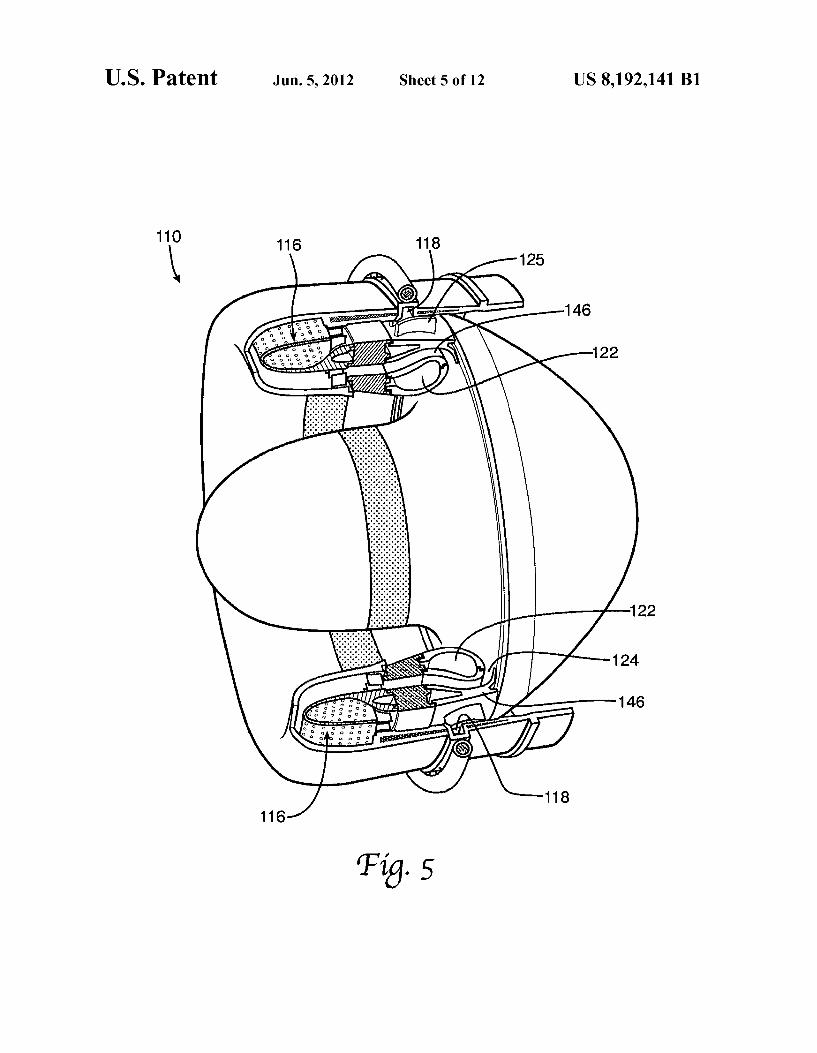
rotor; FIG. 5 is a perspective view of the present invention with
the rotors not shown; FIG. 6 is cross-sectional view of one embodiment of the
gas turbine engine of the present invention; FIG. 7 is a cross-sectional view of another exemplary
embodiment of the gas turbine engine of the present inven tion;
FIG. 8 is a cross-sectional view of a further exemplary embodiment of the gas turbine engine;
FIG. 9 is a cross-sectional view of another exemplary embodiment of the present invention;
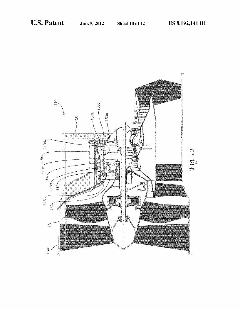
FIG. 10 is a split, cross-sectional view of an exemplary embodiment of the gas turbine engine on top and a conven tional gas turbine engine on bottom;
FIG. 11 is a cross-sectional view of a further exemplary embodiment having a third flow stream; and

US 8,192,141 B1 5
FIG. 12 is a chart showing specific fuel consumption versus thrust.
DETAILED DESCRIPTION OF THE INVENTION
Referring to the drawings, FIG.2 shows a cut-away view of the engine of the present invention, also called the revolution ary innovative turbine engine (RITE) 110. The engine 110 generally includes a dual compression rotor 112, a centrifugal compression rotor 114, a combustion chamber 116, and an inter-turbine burner 118. The rotors 112 and 114 are indepen dently supported about a common axis of rotation. Indepen dent support allows the rotors 112 and 114 to rotate indepen dently of each other as well as rotate in the opposite or same direction. For example, the dual compression rotor may rotate clockwise or counterclockwise, and the centrifugal compres sion rotor may rotate in the opposite direction. Alternatively, the rotors 112 and 114 may both rotate clockwise or counter clockwise. The dual compression rotor 112 is described in more detail with reference to FIG. 6. The centrifugal compression rotor 114 includes a plurality
of blades 120 designed for radial compression of airflow. An annular ring 122 is positioned near the outer edges of the blades 120. The ring 122 forces airflow through a narrow slit 124 to thereby compress air flowing through blades 120. A plurality of tip turbine blades 126 are radially connected with an outer rim 128 and are set at an angle (angle of attack) relative to the axial air/exhaust flow such that the exhaust flow over the blades 126 rotates the centrifugal compression rotor 114. The blades 126 may be angled to rotate the rotor 114 clockwise or counterclockwise. The annular ring 122 and slit 124 form a duct 146 for directing the compressed air in a forward direction and into the combustion chamber 116. The combustion chamber 116 is annular shaped and is
positioned in front of, or up inlet airflow stream of, the dual compression rotor 112. The interior portion of the chamber 116 is generally U-shaped. One end of the U-shape is the entrance of the chamber 116 while the other end is the exit. This configuration allows airflow to enter the chamber in one direction and allows exhaust to exit the chamber in generally the opposite direction (exhaust being the combustion of air and fuel). A second combustion chamber referred to as the inter-turbine burner 118 is positioned between the dual com pression rotor 112 and centrifugal compression rotor 114. The burner 118 is generally annular in shape and is located behind the annular combustion chamber 116 near the periph ery of the engine 110. Both the combustion chamber 116 and inter-turbine burner 118 are supplied with fuel via a fuel delivery system.
Moreover, the chamber 116 and burner 118 may be con trolled independent of each other. That is, the combustion chamber 116 may be supplied with a greater amount of fuel than the burner 118, or vice versa. This independent control permits the operator or engine control computer to regulate the speed of the independently supported rotors: the dual compression rotor 112 and the centrifugal compression rotor 114 (and other rotors as described in subsequent embodi ments). Independent control of the chamber 116 and burner 118 and of the rotors 112 and 114 provides optimum air compression at a variety of engine speeds, air densities, and vehicle velocities. Also, using the inter-turbine burner 118 allows the combustion chamber 116 to be operated at a rela tively lower temperature compared to conventional gas tur bine engines. In conventional engines, combustors can gen erate temperatures of 3600 degrees F. or higher. These extremely high temperatures are needed because there is a loss of heat as the exhaust travels back to the rear turbine
5
10
15
25
30
35
40
45
50
55
60
65
6 blades. In the RITE 110, the combustor 116 temperature is significantly lower (for example, approximately 1900 degrees F.). The RITE's lower temperature reduces or elimi nates the need for cooling systems and reduces the need for expensive heat-resistant materials.
Furthermore, any energy/heat that is lost after the combus tion chamber 116 is reintroduced into the engine 110 by the inter-turbine burner 118 so that the rear turbine blades receive the optimum temperature and pressure. As can be seen by the foregoing explanation of the chamber 116 and burner 118, the RITE 110 creates a near-level temperature engine. That is, each rotor receives the optimal energy, unlike a conventional turbine engine which initially, at the combustor, has extremely high temperatures then the temperature continu ally decreases to the rear of the engine. Other advantages of the independent chamber 116 and burner 118 and of the independent rotors 112 and 114 are provided later in this section.
Also shown in the exemplary embodiment of FIG. 2 is a compressor rotor 130 positioned in front of the dual compres sion rotor 112. The compressor rotor 130 includes a plurality of fan blades 132 for axial compression of inlet air. The rotor 130 may be connected to the dual compression rotor 112 so that the rotors 112 and 130 rotate together. The connection between the rotors 112 and 130 may be rigid (i.e. one-to-one ratio) or may be geared such that compression rotor 130 spins slower or faster than the dual compression rotor 112. Alter natively, the rotor 130 may not be connected to the dual compression rotor 112, but rather may be connected with the centrifugal compression rotor 114 via a shaft. Again, there may be a one-to-one rotation or a gear system that allows the compression rotor 130 to spin slower or faster relative to the centrifugal compression rotor 114. Other configurations of the RITE with a fan rotor are described in subsequent embodi ments, such as in FIG. 7.
Referring now to FIGS.3 and 4, the dual compression rotor 112 compresses air through two stages and provides its own work from its turbine, all on the same rotor. This design configuration eliminates two rotors and a shaft system that connects them in a conventional turbine engine design. The rotor 112 reduces weight, length, and cost. The dual compression rotor 112 includes an inner ring 134,
a plurality of first stage axial compression blades 136, an intermediate ring 138, a plurality of second axial compression blades 140, an outer rim 142, and a plurality of tip turbine blades 144. The inner ring 134 may include bearings for rotational connection to a Support structure. The plurality of first stage axial compression blades 136 are attached radially to the inner ring 134. The blades 136 are set at an angle (angle of attack) relative to the axial airflow such that as the rotor 112 spins the blades 136 move/compress air in a direction from the front of the engine to the back of the engine. The inner surface of the intermediate ring 138 is connected to the outer ends of the compression blades 136, while the second axial compression blades 140 are attached to the outer surface of the intermediate ring 138. The intermediate ring 138 func tions as a structural support for the blades 136 and 140, as well as a barrier separating the airflow through the first axial com pression blades 136 from the airflow through the second axial compression blades 140. The second axial compression blades 140 are radially connected with the intermediate ring 138 and are set at an angle (angle of attack) relative to the axial airflow such that the blades 140 move/compress air in a direction from the back of engine to the front of the engine. The airflow direction through the second axial compression blades 140 is opposite the airflow direction through the first axial compression blades 136.
US 8,192,141 B1 7
The inner surface of the outer rim 142 is attached to the outer ends of the second axial compression blades 140. Con nected to the outer surface of the outer rim 142 is a plurality of tip turbine blades 144. The rim 142 functions as a structural support for the blades 140 and 144, as well as a structure separating the airflow through the second axial compression blades 140 from the airflow through the tip turbine blades 144. The tip turbine blades 144 are radially connected with the rim 142 and are set at an angle (angle of attack) relative to the axial air/exhaust flow such that the exhaust flow over the blades 144 rotates the dual compression rotor 112. The blades 144 may be angled to rotate the rotor 112 clockwise or coun terclockwise. As previously described, the interior portion of the combustion chamber 116 is U-shaped. Therefore, the exhaust flow through the tip turbine blades 144 moves in a direction from the front to the back of the engine (like the airflow through the first axial compression blades).
In operation, the rotor 112 performs two of the primary functions of the turbine engine Brayton cycle: compression and work extraction. Compression is performed by the two axial compressor stages (blades 136 and 140) and work extraction takes place at the tip turbine blades (144). The dual compression rotor can run at uncooled turbine inlet tempera tures (for example 1900 degrees F.) because it does not take much work to drive two axial stages of compression.
However, if higher turbine inlet temperatures are needed to boost performance by adding additional compression stages in front of the dual compression rotor then turbine blade cooling air is on board via radial holes through the outer rim 142 and flows to the root of the turbine blades. The design of the dual compression rotor reduces thermal gradients and is cooled without engine performance penalties. As such, the dual compression rotor can be made from nickel-based or high temperature composite materials allowing for higher temperature capability.
In FIG. 5, the RITE 110 is illustrated with substantial portions of the dual compression rotor 112 or centrifugal compression rotor 114 not shown. This drawing provides a more detailed view of the combustion chamber 116 and inter turbine burner 118. The annular ring 122 and the body (not shown) of the centrifugal compression rotor 114 define the slit 124 through which air is compressed. The duct 146 steers the airflow forward to the dual compression rotor 112. Com pressed air exiting the rotor 112 enters the combustion cham ber 116. The U-shaped chamber 116 reroutes the airflow and exhaust gas aft towards the tip turbine blades of the rotor 112. The inter-turbine burner 118, positioned between the rotors 112 and 114, adds heat and energy to the exhaust which then travels through flow-steering stators XXX and to the tip tur bine blades 126 (not shown) of the centrifugal compression rotor 114. The air/exhaust flow path of the RITE 110 can be seen in
FIG. 6. Cool inlet air enters the dual compression rotor 112. The air gets compressed by the first axial compressor stage? blades 136. Then, the air enters the centrifugal compressor rotor 114 that further compresses the air. Aduct 146 turns the airflow toward the front of the engine (typical turbine engines turn airflow toward the rear directly into the combustor). The ducted airflow then enters the dual compression rotor 112 to be compressed by the second axial compressor stage/blades 140. This compressed air mixes with fuel and burns in the combustor chamber 116. The exhaust gas passes through the tip turbine blades 144 to drive the dual compression rotor 112. Then, the exhaust flow enters the inter-turbine burner 118 to boost the temperature before passing through the tip turbine blades 126 to drive the centrifugal compression rotor 114.
10
15
25
30
35
40
45
50
55
60
65
8 Another exemplary embodiment of the present invention is
shown in FIG. 7. This embodiment is similar to the embodi ment shown in FIG. 2. The RITE 110 includes a compressor rotor 130, a plurality of stators 148, a dual compression rotor 112, a centrifugal compression rotor 114, a combustion chamber 116, and an inter-turbine burner 118. The compres sor rotor 130 is rotationally connected with the dual compres sion rotor 112. In operation, inlet air is compressed by the compressor rotor 130. The compressed air is redirected by the stators 140 then is compressed by the first axial compression stage/blades 136 of the dual compression rotor 112, and the centrifugal compression rotor 114. The duct 146 then turns the flow of compressed air forward and through the second axial compression stage/blades 140 of the dual compression rotor 112. The optimally compressed air is then mixed with fuel in the combustion chamber 116. The exhaust gas rotates the dual compression rotor 112 via the tip turbine blades 144. Then, the inter-turbine burner 118 increases the temperature/ work capability of the exhaust gas which in turn rotates the centrifugal compression rotor 114 via the tip turbine blades 126. As described in a previous embodiment, the dual com pression rotor and centrifugal compression rotor may be inde pendently controlled by controlling the combustion chamber and inter-turbine burner independently. The exemplary embodiment of FIG. 8 has two dual com
pression rotors 112a and 112b and two inter-turbine burners 118a and 118b. The other components and features of the RITE shown in FIG. 8 are similar to the previously described embodiments. In the current embodiment, the two dual com pression rotors 112a and 112b and centrifugal compression rotor 114 are independently supported rotors. That is, rotors 112a, 112b, and 114 may rotate independent of each other, and may rotate at different speeds relative to each other. Different rotor speeds are achieved by independently control ling the fuel burn in the combustion chamber 116 and the two inter-turbine burners 118a and 118b. The combustion cham ber 116 generally controls the rotation of the first dual com pression rotor 112a, the first inter-turbine burner 118a gen erally controls the rotation of the second compression rotor 112b, and the second inter-turbine burner 118b generally controls the rotation of the centrifugal compression rotor 114.
In operation, inlet air of the engine 110 in FIG. 8 is com pressed, in order, by the first axial compression stage/blades 136a of the first dual compression rotor 112a (then redirected by the stators 140), the first axial compression stage/blades 136b of the second dual compression rotor 112b, the centrifu gal compression rotor 114, the second axial compression stage/blades 140b of the second dual compression rotor 112b (then redirected by the stators 140), and the second axial compression stage/blades 14.0a of the first dual compression rotor 112a. After ignition in the combustion chamber 116, the exhaust flow, in turn, drives the first dual compression rotor 112a (via turbine blades 144a), gets reheated with inter turbine burner 118a, drives the second dual compression rotor 112b (via turbine blades 144b), gets reheated with inter turbine burner 118b, and drives the centrifugal compression rotor 114 (via turbine blades 126).
It is contemplated that the embodiment of FIG. 8 may include more than two dual compression rotors and/or more than two inter-turbine burners. In Such a configuration, the inter-turbine burners would be placed between the rotors so the exhaust flow can be reheated to obtain higher pressure ratios.
Referring now to FIG.9, the RITE 110 (turbofan configu ration) includes a fan rotor 131, dual compression rotor 112, centrifugal compression rotor 114, duct 146, combustion chamber 116, first and second inter-turbine burners 118a and

US 8,192,141 B1
118b, and turbine rotor 150. Turbine rotor 150 is connected with fan rotor 131 via a shaft for a one-to-one rotation ratio. Alternatively, the shaft may include a gearbox for providing a less than or greater than rotation ratio between rotors 131 and 150. The rotors 112, 114, and 131 with 150 are independently Supported, and their speeds may be independently controlled by the combustion chamber 116 and inter-turbine burners 118a and 118b. The path of air/exhaust flow in this embodi ment is substantially similar to previously described embodi ments. One point of difference is that the second inter-turbine burner 118b drives the turbine rotor 150 which in turn drives the fan rotor 131. This embodiment may include other com ponents described herein, Such as two or more dual compres sion rotors, three or more inter-turbine burners, and two or more fan rotors/turbine rotors. The top half of FIG. 10 illustrates yet another embodiment
of the present invention. The bottom half of FIG. 10 shows a conventional gas turbine engine (prior art). The two views are placed side-by-side for easy comparison and contrasting. For example, the RITE view shows a reduction in length, number of components, and complexity compared with a conven tional gas turbine engine design concept. The top embodi ment of FIG. 10 includes, in part, an inlet guide vane 154, one shaft- or gear-driven fan rotor 131, a compressor rotor 130 connected with a dual compression rotor 112, a centrifugal compression rotor 114, airflow duct 146, combustion cham ber 116, four inter-turbine burners 118a-d, one turbine rotor with two stages 150a and 150b, one free/power turbine 150c, and an exit guide vane 156. The inter-turbine burner 118c is located between two turbine stages 150a and 150b of the same turbine rotor. The embodiment of FIG. 11 includes, in part, an inlet guide vane 154, one shaft- or gear-driven fan rotor 131, a compressor rotor 130 connected with a dual compression rotor 112, a centrifugal compression rotor 114, airflow duct 146, combustion chamber 116, three inter-tur bine burners 118a-c, one turbine rotor 150a, one free/power turbine 150b, and an exit guide vane 156. The free/power turbine in FIGS. 10 and 11 extracts work from and controls the third stream by-pass air to match inlet airflow, thereby reducing airflow spillage and decreasing vehicle drag. The air and exhaust flow can be better seen in FIG. 11. Air
flows through the engine 110 through three paths: the inlet flow control path A, the main bypass flow path B, and the core flow path C. Path A airflow, third stream flow, varies to match the inlet design airflow, eliminating vehicle inlet spillage drag. In path A, fan-on-turbine rotor speed/airflow is con trolled by inter-turbine burner 118c and power extraction. (Power extraction from an attached generator as Subsequently described). Path Bairflow, by-pass flow, varies the fan rotor speed/main bypass airflow to provide the required vehicle thrust and is controlled by inter-turbine burner 118b and power extraction. Path Cairflow, flow through the RITE core, is kept constant at the core design point for highest efficiency.
Also shown in FIGS. 10 and 11 is a plurality of generators 152. One or more generators may be connected with each independently supported rotor, like the fan rotors, dual com pression rotors, centrifugal compression rotor, and/or turbine rotors. Because the rotational speed of each independently support rotor can be controlled via the combustion chamber and/or inter-turbine burner, the output of each generator may be controlled. Having a plurality of independent generators provides several layers of backup and auxiliary power Sources. When power demand is high, most or all generators can be activated and their output can be controlled. When the need for power is reduced, some independent generators may be taken off-line, and the inter-turbine burner(s) driving the rotor which turns the generator can be reduced, saving fuel
10
15
25
30
35
40
45
50
55
60
65
10 and increasing efficiency. As seen in FIGS. 10 and 11, the power generating components of the generators may be posi tioned on a rotor as well as on a stationary Support structure. It is contemplated that the generators may also function as magnetic bearings between rotors and between rotors and stationary Support structures. These dual-use generators/ magnetic bearings can eliminate the need for mechanical bearings which can add weight and require cooling systems. A Brayton cycle chart is illustrated in FIG. 12. In the graph,
SOATF is state of the art turbofan core, SFC is specific fuel consumption, PR is pressure ratio, TRIT is turbine rotor inlet temperature, Fn/Wa is thrust/airflow. Running the cores and turbojets (core with exhaust nozzle), the RITE has an improved SFC to thrust ratio compared to state of the art turbofan cores. RITE 1 corresponds to the embodiment shown in FIG. 6. RITE 2 corresponds to the embodiment of FIG. 7. RITE 3 corresponds to the embodiment of FIG. 8. Analysis shows that the RITE has one-third less fuel con Sumption compared to state-of-art engines at the same thrust level.
While various descriptions of the present invention are described above, it should be understood that the various features can be used singularly or in any combination thereof. Therefore, this invention is not to be limited to only the specifically preferred embodiments depicted herein. Further, it should be understood that variations and modifications within the spirit and scope of the invention may occur to those skilled in the art to which the invention pertains. Accordingly, all expedient modifications readily attainable by one versed in the art from the disclosure set forth herein that are within the Scope and spirit of the present invention are to be included as further embodiments of the present invention. The scope of the present invention is accordingly defined as set forth in the appended claims. What is claimed is: 1. A gas turbine rotor comprising: a plurality of first axial compression blades configured for
compressing air in a first direction, the plurality of first axial compression blades having a first blade quantity and a first blade height; and
a plurality of second axial compression blades configured for compressing the air from the first axial compression blades in a second direction, the second direction being generally opposite the first direction, the plurality of second axial compression blades having a second blade quantity that is greater than the first blade quantity and a second blade height that is less than the first blade height, wherein the plurality of second axial compres sion blades are discontinuous with the plurality of first axial compression blades and extend radially outward from the plurality of first axial compression blades such that the plurality of second axial compression blades are substantially coplanar with the plurality of first axial compression blades.
2. The rotor of claim 1 further comprising an intermediate ring connected to outer radial ends of the plurality of first axial compression blades and connected to inner radial ends of the plurality of second axial compression blades.
3. The rotor of claim 2 wherein the intermediate ring is a barrier between the air compressed by the plurality of first axial compression blades and the air compressed by the plu rality of second axial compression blades.
4. The rotor of claim 3 further comprising a rim connected to outer radial ends of the plurality of second axial compres sion blades.
5. The rotor of claim 4 further comprising a plurality of turbine blades, wherein the plurality of turbine blades are

US 8,192,141 B1 11
discontinuous with the plurality of second axial compression blades such that the plurality of turbine blades have a third blade quantity that is greater than the second blade quantity and a third blade height that is greater than the second blade height, the inner radial ends of the plurality of turbine blades 5 being connected to the rim.
6. The rotor of claim 5 wherein the plurality of turbine blades is configured such that the rotor rotates clockwise as exhaust gas passes over the plurality of turbine blades.
7. The rotor of claim 5 wherein the plurality of turbine to blades is configured Such that the rotor rotates counterclock wise as exhaust gas passes over the plurality of turbine blades.
8. The rotor of claim 5 wherein the rim is a barrier between the air compressed by the plurality of second axial compres sion blades and exhaust gas traveling over the plurality of is turbine blades.
9. A gas turbine rotor comprising: an inner ring: a plurality of first axial compression blades connected to
the inner ring, the plurality of first axial compression blades having a first blade quantity and a first blade height;
an intermediate ring connected to the plurality of first axial compression blades;
a plurality of second axial compression blades connected to the intermediate ring, the plurality of second axial
12 compression blades having a second blade quantity that is greater than the first blade quantity and a second blade height that is less than the first blade height, wherein the plurality of secondaxial compression blades are discon tinuous with the plurality of first axial compression blades;
a rim connected to the plurality of second axial compres sion blades; and
a plurality of turbine blades connected to the rim, the plurality of turbine blades having a third blade quantity that is greater than the second blade quantity and a third blade height that is greater than the second blade height, wherein the plurality of turbine blades are discontinuous with the plurality of second axial compression blades.
10. The rotor of claim 9 wherein the plurality of first axial compression blades compress air axially in a backward direc tion when the rotor rotates.
11. The rotor of claim 10 wherein the plurality of second axial compression blades compress the airina forward direc
0 tion when the rotor rotates. 12. The rotor of claim 11 wherein the plurality of turbine
blades is configured for rotating the rotor when exhaust gas passes by the plurality of turbine blades.