(12) united states patent (10) patent no.: us 8,036,152 b2 ... · assignment 6,879,567 sys- b2...
TRANSCRIPT
USOO8036152B2
(12) United States Patent (10) Patent No.: US 8,036,152 B2 BrOWn et al. (45) Date of Patent: Oct. 11, 2011
(54) INTEGRATED POWER MANAGEMENT OF A 5,517,502 A 5/1996 Bestler et al. CLIENT DEVICEVA SYSTEM TIME SLOT 88: , '858. S., a 455,265
sys- SOl Cal. ...............
ASSIGNMENT 6,879,567 B2 4/2005 Callaway et al. 6,889,067 B2* 5/2005 Willey .......................... 455,574
(75) Inventors: David L. Brown, Jupiter, FL (US); Fred 7,031945 B1 4/2006 SN, S. Hirt, Brookfield, IL (US) 7,068,623 B1 6/2006 Barany et al.
7,130,668 B2 * 10/2006 Chang et al. .................. 455,574 (73) Assignee: Proxense, LLC, Bend, OR (US) 7,277,737 B1 * 10/2007 Vollmer et al. ... 455,574
9 s s 7.460,836 B2 * 12/2008 Smith et al. ... 455/67.11 7,573,841 B2* 8/2009 Lee et al. ... 370,311
(*) Notice: Subject to any disclaimer, the term of this 7,583,643 B2 * 9/2009 Smith et al. ........ 370,338 patent is extended or adjusted under 35 2002/00224.55 A1 2/2002 Salokannel et al. ............ 455.68 U.S.C. 154(b) by 537 days. 2002/0177460 A1 1 1/2002 Beasley et al.
2003/0036416 A1 2/2003 Pattabiraman et al. ....... 455,574 2003/01 17969 A1* 6, 2003 370,318
(21) Appl. No.: 11/620,603 2004/0029620 A1* 2/2004 Karaoguz ..................... 455,574 (22) Filed: Jan.5, 2007 2004/OO29635 A1 2/2004 Giobbi
e a 9 (Continued)
(65) Prior Publication Data OTHER PUBLICATIONS
US 2007/02O7750 A1 Sep. 6, 2007 PCT International Search Report and Written Opinion, PCT/US07/
Related U.S. Application Data 00349, Mar. 19, 2008, 10 pages.
(60) Provisional application No. 60/760.362, filed on Jan. 6, 2006. Primary Examiner — Kent Chang
Assistant Examiner — Magdi Elhag (51) Int. Cl. (74) Attorney, Agent, or Firm — Patent Law Works LLP
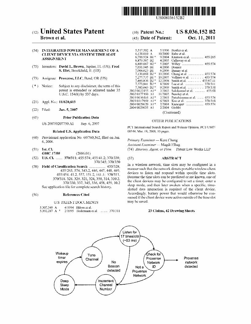
GOSC 17/00 (2006.01) (52) U.S. Cl. ....... 370/311:455/574; 455/412; 370/338; (57) ABSTRACT
370/345; 370/350 (58) Field of Classification Search 455/328 In a wireless network, time slots may be configured in a
455/265, 574,343.2, 446, 447. 448. 449 manner such that the network directs portable wireless client 455/454 412 557 1512 1611. 370/31 1. devices to listen and respond within specific time slots.
370/318 328 339 321 324. 350 314 3102. Because the time slots can be predicted or are known, one of 370,330, 3.37. 345. 336. 458. 459. 102 the client devices may be configured to set a timer, enter a
See application file for complete search histo sleep mode, and then later awaken when a specific, time pp p ry. slotted data interaction is required of the client device.
(56) References Cited Accordingly, battery power that would otherwise be CO sumed if the client device were active outside of the time slot
U.S. PATENT DOCUMENTS may be saved. 5,307,349 A 4, 1994 Shloss et al. 5,392.287 A * 2/1995 Tiedemann et al. .......... 370,311 23 Claims, 42 Drawing Sheets
listen for innesots
(-83 ms)
Wakeup tifier Proxense Proxerse
expires No Network network Beacor. Not a detected detected Proxense
Network Cefnet Channel Nirbet

US 8,036,152 B2 Page 2
U.S. PATENT DOCUMENTS
2004/004.8570 A1 2004/0082385 A1 2005/0047386 A1* 2005.0049013 A1* 2005/0090200 A1
3, 2004 4, 2004 3, 2005 3, 2005 4, 2005
Oba et al. Silva et al. Yi ................................. 370,345 Chang et al. .................. 455,574 Karaoguz et al.
2006.0025 180 A1* 2006, OO3O353 A1* 2006/O194598 A1* 2006/O198337 A1* 2007, OO60.095 A1*
* cited by examiner
2, 2006 2, 2006 8, 2006 9, 2006 3, 2007
Rajkotia et al. ............... 455,574 Jun .............. 455,550.1 Kim et al. ... 455,509 Hoang et al. .................. 370,329 Subrahmanya et al. ... 455/343.1

U.S. Patent Oct. 11, 2011 Sheet 1 of 42 US 8,036,152 B2
arrissan
Y n 1 \
Celi boundary Wireless 1. link \ -z
Backed W Communications 8. PK channel (user) l
?-d N '7- /
N - s --
FIGURE 1.
FIGURE 2

U.S. Patent Oct. 11, 2011 Sheet 2 of 42 US 8,036,152 B2
FIGURE 3

U.S. Patent Oct. 11, 2011 Sheet 3 of 42 US 8,036,152 B2
CROC Ce
FIGURE 4
U.S. Patent Oct. 11, 2011 Sheet 4 of 42 US 8,036,152 B2
Service and Application layer Controller Wireless RF a MAC and PY
& 8 device Secure Key Crypto
Storage Engine
Wolatile Woiatite Power E-Connierce Service Management
Storage Provider Storage
s *
s - G
O
FIGURES

U.S. Patent Oct. 11, 2011 Sheet 5 of 42 US 8,036,152 B2
Non-Volatile Memory Wolatite Memory Secure Key Storage Service Provider Storage
Service Provider Profile
Service Provider 2 Profile
Service Provider 3 Profile
Service Provider n Profite
Public Seria Nibef
Secret Serial Number (i.e. Credit Card Number)
Crypto Key
FIGURE 6
U.S. Patent Oct. 11, 2011 Sheet 6 of 42
Wolatite Memory Service Provider Storage
Service Providef POKS identification Service Provider Site identification
Service Provider Service identification
Service Provider Secret Key Byte Count
Service Provider variable ength data
FIGURE 7
US 8,036,152 B2
Bytes Byte Count
U.S. Patent Oct. 11, 2011 Sheet 7 of 42 US 8,036,152 B2
22. Service and Application
Wired correctors ---, layer Controsef Wireless RF wifros MAC and Phy
Service Provider System device Service rowder
interace
Sack-ed systs Service K-M Provider
Controller
Parameters
Secure Key
Stofage
Power Management
Proximity tracking pok tist
Service Provide Storage Basic RC
FIGURES

U.S. Patent Oct. 11, 2011 Sheet 8 of 42 US 8,036,152 B2
Y2
wore fl-n Wifeless RF S Tolfront Systern MAC and PY evice towicer
second so Service Service Parafeters device * Provider Prewicer & 3. X
Controker interface Configuration s
ina.mmu.ir : og Wireless RF Associated Crypto Secure
t poss Engine Key MA and PHY Parameter Storage 3WCe
8. Storage Proximity Wolate
a poks Provide it Management list Storage
Basic ROC with a PHY
FGURE 9
U.S. Patent Oct. 11, 2011 Sheet 9 of 42 US 8,036,152 B2
Wariable Variable 0 - 286 symbols 2 - 40 symbois
Frame (PPD) FS
10 2 254
"www. *ress. MAm. "---
-
s Y.
w s
s
babbatabab.bab,
FIGURE O

U.S. Patent Oct. 11, 2011 Sheet 10 of 42 US 8,036,152 B2
Superframe
Ts. Its, ts. Its, ts. is is, 8eacon
FIGURE

U.S. Patent Oct. 11, 2011 Sheet 11 of 42 US 8,036,152 B2
Coordinator Superframe
FIGURE 2
U.S. Patent Oct. 11, 2011 Sheet 12 of 42 US 8,036,152 B2
Coordinator Superframe
"'re Y------woo... Superframe MrrWwww.
rs, is is, is is. Irs. Its, 8eacon i.
Timeslot
Wariable Q - 286 symbols
S4
ls n s N sa
s babbbbbbs,
FIGURE 3

U.S. Patent Oct. 11, 2011 Sheet 13 of 42 US 8,036,152 B2
Response & bidirectional
Communications
1 Y --Na
Y - Beacons
FGURE 4

U.S. Patent Oct. 11, 2011 Sheet 14 of 42 US 8,036,152 B2
/ w Cell bounday Wireless AV-1
link
rz.
FIGURE S

U.S. Patent Oct. 11, 2011 Sheet 15 of 42 US 8,036,152 B2
ROC PKS ROC Beacon Beacon Broadcast
inter Exhausted POK detects beacon and
PDK Response Broadcast broadcasts PDK ROC detects PDK8 location Response with close proximity and requests a tink
to POK. ifik Request POK Oetects
e request and replies ROC detects ink Link Graft with ink grant
rait and begins
with POK8, ata Exchange with ROC.
(Periodic data exchange) Oata exchange
User walks away from RDC determines POK Game, in no longer in range and disabies game
play,
CRC Beacon Beacon Broadcast finer Exhausted
FIGURE 6
U.S. Patent Oct. 11, 2011 Sheet 16 of 42 US 8,036,152 B2
) () (b.
SF SF, SF SF SF : e
Beacoris Sent ROC p)KS From CROC Bidirectional communications
FIGURE 7
U.S. Patent Oct. 11, 2011 Sheet 17 of 42 US 8,036,152 B2
SF Cnt $2 bits) iS Cat (4 bits)
Part of Unique user D (15 bits)
TXTS. Enable
FIGURE 8

U.S. Patent Oct. 11, 2011 Sheet 18 of 42 US 8,036,152 B2
Backed r Communicatifs . S. t
RC charai (Fixed part | Y
A
Sa i Backer. officatios chaire
t is essasswiss i
FIGURE 9
U.S. Patent Oct. 11, 2011 Sheet 19 of 42 US 8,036,152 B2
CROC RC ROC2 pK8 Server Beacon Broadcast
POK)etects beacor and broadcasts PDK location Respoise
POK Response Broadcast Send POK iO and Signal Quality to Server Server application
logs POK's iO and signal quality metrics for location tracking.
Send POKO and Signal Quality to Server
Y N F. PDK Response Broadcast Y sendpoks band
Signal Quality to Server Send POKER and Signal Quality to Server
Beacon Broadcast
PEOK8 Detects teacon aid broadcasts PDK location Response
Server application logs PDK1 and signal quality metrics for location tracking,
FIGURE 20
U.S. Patent Oct. 11, 2011 Sheet 20 of 42 US 8,036,152 B2
CRDG Cel: Boundary 1 Beacon. Only A
eggahasar
Ce8 ce: 4 go
Y Ceil 2 Ces 8. ear agalpageares
s Ce: 3 Ce:8 St.A
7
FIGURE 21
U.S. Patent Oct. 11, 2011 Sheet 21 of 42 US 8,036,152 B2
r "w,
Tr"Marm--- axeswl. --- Trrrrrrror traw
is 3 so e o is is
FIGURE 22

U.S. Patent
CRC CHAN
CRC Beacon timer expires and updates Superframe inforfration and broadcasts.
CRC Beaco timer expires and updates Superframe iforniation afd broadcasts.
Oct. 11, 2011
C-Beacon.
ROC? coijects and logs PDK information afd sends it to the Sewer
C-Beacon
ROC collects and jogs PDK information and sends it to the Server
ROC CHAN 1
Sheet 22 of 42 US 8,036,152 B2
ROC CHAN POK8
POK Receives C-Beacon and responds on its next
PDK. Location Response predefined odd tirnesot
ROC Collects and logs POK information and sends it to the Sever
POK Receives C-Beacon and responds on its next predefined odd timeslot POK. Location Response
RC2 Coects and logs PDK8 information and Sercis it to the Sewer
FGURE 23
U.S. Patent Oct. 11, 2011 Sheet 23 of 42
CRDC CAN CHAN CHAN 2
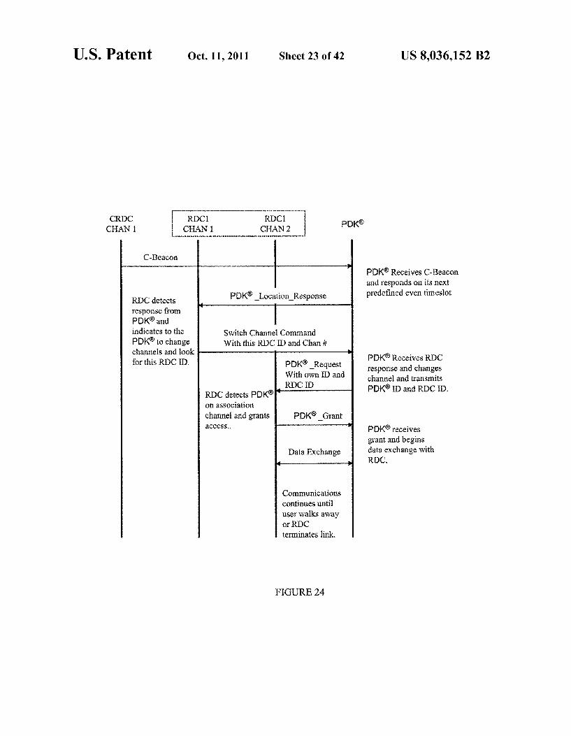
PDK. Location Response RDC detects response from PDKs and indicates to the Switch Channel Command PDK to change With this RIDC ID and Chani channels and look for this R.C), PDK Request
With own D and ROC O.
RDC detects PDK on association channel and grants CSS.
PDK8 Grant
iData Exchange
Communications continues until user walks away or RC terminates link,
FIGURE 24
Poké
US 8,036,152 B2
PDK Receives C-Beacon and responds on its next predefined even timeslot
PDK Receives RDC response and changes channel and transmits PDK3ID and RDC ID,
PDK receives grant and begins data exchange with ROC,
U.S. Patent Oct. 11, 2011 Sheet 24 of 42 US 8,036,152 B2
Beacons sent From ROC
SF SF SF SF SF
Superframe Count N Frame Check Sequence
--- *Man... Man--- rena
Network Format rearwave r
“"me.-----.
rrn --
REC 3
ww.
num Proxense Network to
FGURE 25
U.S. Patent Oct. 11, 2011 Sheet 25 of 42 US 8,036,152 B2
listen for timeslots
(-83 ms)
Wakeup tifier Proxense Proxense
expires No Network network Beacon Not a O detected detected Proxense
Network crenefit Channel Nurnber
FIGURE 26
U.S. Patent Oct. 11, 2011 Sheet 26 of 42 US 8,036,152 B2
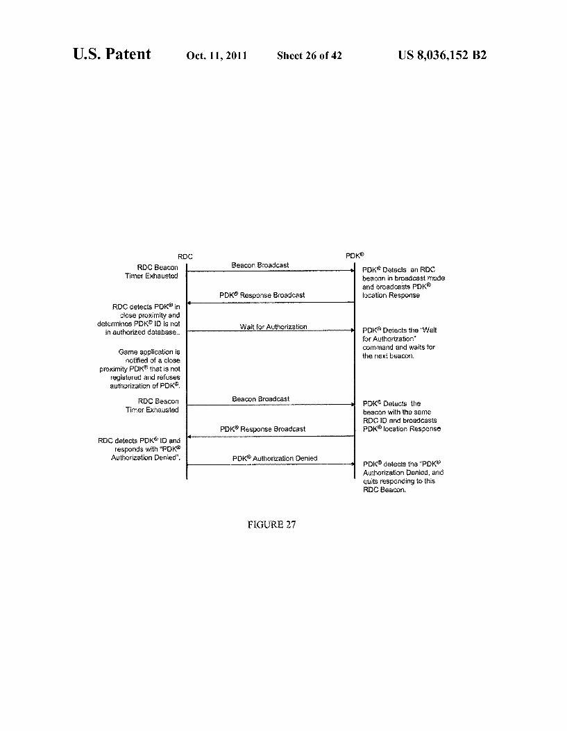
RC PK8 RC Beacon
inter Exhausted
ROC detects POK in close proximity and
determines POK 3D is not in authorized database.
Game apptication is inotified of a close
proximity PDK that is not registered and refuses authorization of POK,
ROC Beacon finner Exhausted
ROC detects PDKE) and responds with “POK
Authorization Denied".
Beacon Broadcast
PDK Response Broadcast
Wait for Authorization
Beacon Broadcast
PDK Response Broadcast
POK Authorization Denied
FIGURE 27
POK8 Detects an REC beacon in broadcast mode and broadcasts PDK location Response
PDKs Detects the "Wait for Authorization" command and waits for the next teaCon,
POK. Oetects the beacon with the same RC) and broadcasts PDK location Response
pK8 detects the "POK Authorization Renied, and quits responding to this RC Beacon,
U.S. Patent
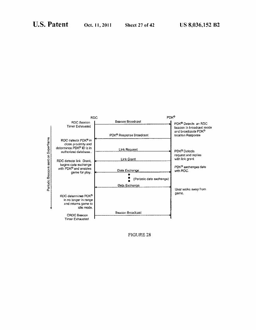
RC RBC Beacon
Timef Exhausted
RDC detects PDK3 in close proximity and
determines PDK D is in authorized database.
ROC detects ink Giant, begins data exchange
with POK and enables game for play,
ROC determines PDK in no longer in range and returns game to
idle node.
CROC Beacon inef Exhausted
Oct. 11, 2011 Sheet 27 of 42 US 8,036,152 B2
poks
POK8 Detects an ROC beacon in broadcast rode and broadcasts POK
Beacon Broadcast
PDK Response Broadcast location Response
PDK8 Oetects
tink Grant with link grant
with ROC. PDK exchanges data
(Periodic data exchange) Data Excharge
User walks away from game.
Beacon Broadcast
FGURE 28

U.S. Patent Oct. 11, 2011 Sheet 28 of 42 US 8,036,152 B2
Beacons sent From RC
SF SF, SF, SF SF 8 8 O
Y-- N--
POK8 POK& 2
FGURE 29
U.S. Patent Oct. 11, 2011 Sheet 29 of 42 US 8,036,152 B2
FIGURE 30

U.S. Patent Oct. 11, 2011 Sheet 30 of 42 US 8,036,152 B2
Casino Floof and Gaming able area
serer
- O Registration Cei
Certa Serve 22 O
FIGURE 3

U.S. Patent Oct. 11, 2011 Sheet 31 of 42 US 8,036,152 B2
Player 4
^ Player 7 Player 1 Y.
FGURE 32

U.S. Patent Oct. 11, 2011 Sheet 32 of 42 US 8,036,152 B2
start-Vrrrrtorv, seas"
Y
- Y
PRK totation racking Cetts
astratf
Yvvy Tyrro u-1 - Centra Server ...r."
CROC Ceit Baufdary
S2.
FIGURE 33
U.S. Patent Oct. 11, 2011 Sheet 33 of 42 US 8,036,152 B2
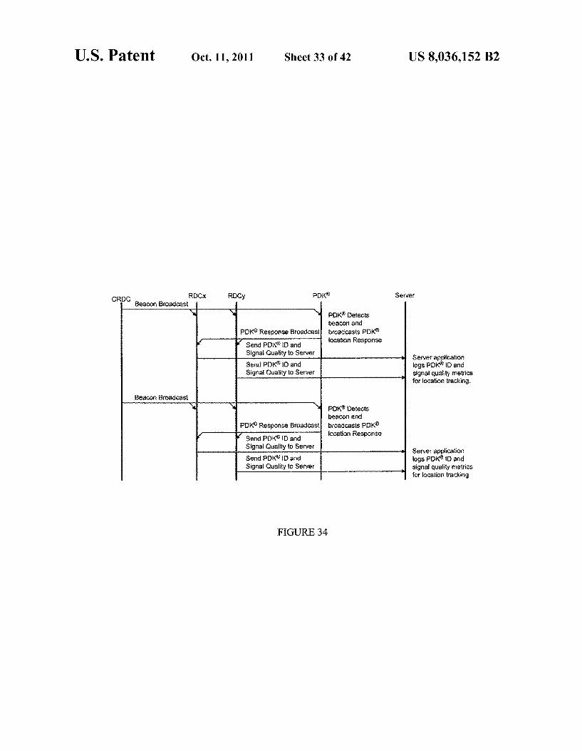
CROC ROCx ROCy POK Server Beacon Broadcast
POK8 Detects beacor afic broadcasts POK iocation Response Y send PDKsband
Signal Quality to Server Send PK8) arid Signal Quality to Server
POK. Detects beacon and broadcasts POK ?ocation Response
Server applicatio fogs POKD and signat quality metrics for iocation tracking,
Beacon Broadcast
POK Response Broadcast Y send Poks to and
Signal Quality to Server Send POKS ED and Signal Quality to Server
Server application logs PDK iD and signal quality metrics for location tracking.
FIGURE 34
U.S. Patent Oct. 11, 2011 Sheet 34 of 42 US 8,036,152 B2
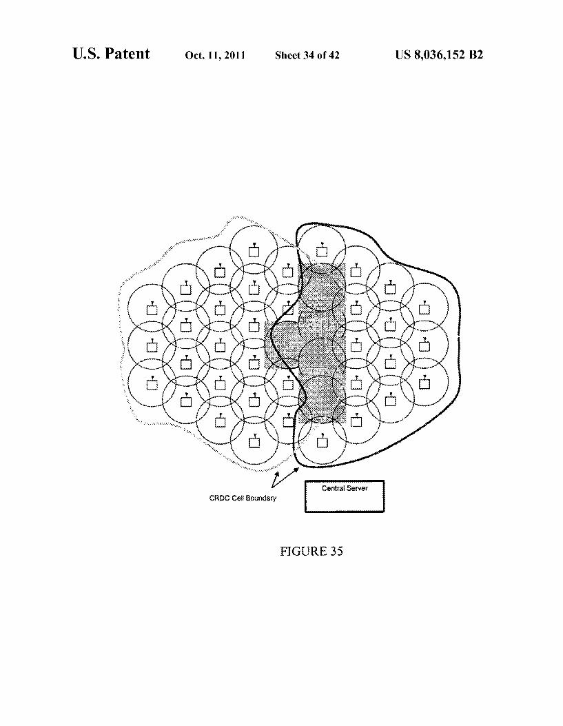
Cefira Seryer CROC Ce: Boundary
FIGURE 35
U.S. Patent
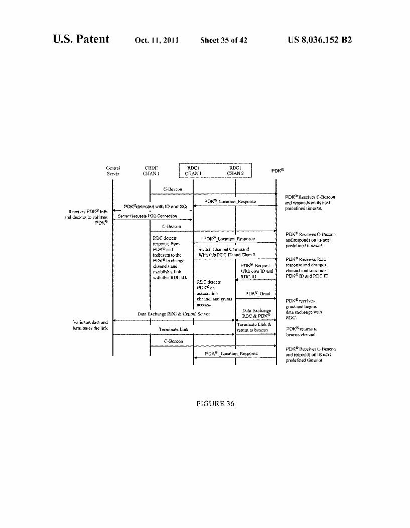
Centra Server
Receives POK info and decides to validate
poks
Walidates data and terminates the ink
Oct. 11, 2011
POKaetected with D and SQ
Server Requests POO Connection
C-Beacon
RX detects response from POK and indicates to the POK to change channels aid establish a link with this RCD,
Data Exchange RDC & Central Server
Terminate link
Sheet 35 of 42
ROC ROC CAN CHAN2
POK Location Response
POKilocation. Response Switch Channel Command With this ROCs and Chani
POK Request With own aid RECE)
RC detects poks on association channel and grants 3CCSS.
Data Exchange RDC & POK
eraliate link & return to beacon
POK. Location Response
FIGURE 36
POK Grant
US 8,036,152 B2
poks
PDK Receives C-Beacon and responds on its next predefined timeslot
POK Receives C-Beacon and responds on its next predefined timeslot
POK Receives RDC Fesponse and changes channel and transmits POKB) and ROC D.
POK receives grant and begins data exchange with RX.
POKreturns to beacois chaise
P}X Receives C-Beacon and responds on its next predefined timeslot

U.S. Patent Oct. 11, 2011 Sheet 36 of 42 US 8,036,152 B2
Enter discovery mode
No Beacon Detected
Access other CRC
Charines Wait for innesot
Beaco Select Detected
ey
charine Perfor CSAA-CA
ife Receiver
Wrong Superframe Wakeup
inter expires
Setup for Next
Wakeup superframe Wait for
REC response
No RC response
Wakeup POK changes to re aefrate care
RC change channel response
FIGURE 37

U.S. Patent Oct. 11, 2011 Sheet 37 of 42 US 8,036,152 B2
Electronic Game Housing
Basic RC with Oai PHY
Service and Applications layef of trief Wireless RF
garreror. SAC and P-Y Ofrom Service Service System device
Central Server E. : Provider Paapeers ranslator Wia Wireline interface interface
'why sweps to
Associated Wireless RF poks Secure MAC and PHY
Parasimeter so device From AC Outlet Storage
Proximity tracking pks tis
Electronic Game
of Fron Service User Central Server Provide EY Via Wireline interface terface
Microcontroiter &
Application Software
Usef From AC Cutlet input
interface
FIGURE 38
U.S. Patent Oct. 11, 2011 Sheet 38 of 42 US 8,036,152 B2
Catra Eactronic Sever Game RC pK& Player
POK response ?e sects
Central Sswer RC Detected Poke & so -- - - - - - - - - c-Beacon not shown Deistis PKID and and fessords Keoks up user name Scissa ask player to play
Visible ancier audio display with users first rare
Player presses a button of 8 game Send status that plays, has responded via
sta Sewer game interface Oekects sers response
and fees a correction & cookis. Command Ric to take PDK connection POKOetects
C-8sacon not show) pks ssporiss and responds
Switch Chate Corna pictetects switch
Playersees the game and walks up and presses a button
PRKirk Request alterate carries as
POKirk Grant Sfas lik PCees craft
and aegirls periodic Eata Exchange data exchange yia
Cesa Serer ROC resorts ink confecte association detects association with
POKoccurred and send command to display instructs player to press press PRK button now visible display "Press POK button now Player sees the
the PRK button. - may s --------------------------- finessage at:
POK button Ekbutton depressed presses their Pok POK button depressed status depressed status tutor Centra: Server detects
player pressed POK game for play Enable garrie of pay
ution anxi enables Etes
FIGURE 39
U.S. Patent Oct. 11, 2011 Sheet 39 of 42
Centra Electronic Server Game ROC pK8
Central Sewer stables ths garrie for pla
and erass P. going
Centras Sarver detects PCR is no longer
in range and returns game to its ice condition
Ceintral Server Reguests statistics for
player and stores them in local catatase
Eable game for play
Erable OK Poiting
ROC Periodicaity potis POKard
checks response R 5::::sik diseased
REC Periodicaily polis PDK and
checks response
K3 exists ...ax exeggiac
ROC Periodically polis POKEut no
response, so it airies 2 issoe iss
ROC reports ROK out of tange
Rs. 3 ce. Sara returns to rofinal ice scrass
Request game statistics
Return Statistics
Statistics for player packetized and set back to Central Server
Payer interacts with garne
OK Po:
POKresponse
pokpo.
POK response
PKS Poi akpot
Pokro:
FIGURE 40
POKoetects PoE and responds
POKOstects rot and responds
US 8,036,152 B2
Player
Player plays the game
Player walks away from game.

U.S. Patent
of From Central Server Wia Wifeline
From AC Outlet
Oct. 11, 2011
Service Provider ranslatof
interface govo vow voove
w r
t X P e th
a P. P
s s
A. F
As
d
t p w w
w
s o
w Y. p
RDC interface
Service Provider interface
Sheet 40 of 42
Electronic Game Housing
easie ROC with Dua PHY
Servite and Application Layer Controller
Service Provider interface
Parameters &
Configuration
Associated pK&
Paranteef
Proximity yotable racking Service
Provider Stofage
Electronic Game
Microcontroller &
Application Software
FIGURE 4
US 8,036,152 B2
Wireless RF MAC as Y
dswice
Wireless RF MAC and PY
device
ser Display interface
U.S. Patent Oct. 11, 2011 Sheet 41 of 42 US 8,036,152 B2
Central Electronic 8 p Server Game ROC pK layer
REC detected Eig Poko & SQ POKresponse POKDetects Centra Server C-Beacon (not shown)
Detects POKD and Send POK'information and esponds kooks ug usef fare to Game
With free game indicator Wisible and of audio display with users first name
Player sess the Garse alerts sor via wisible or audio and Player presses a button on the game game arc walks up and pesses a lot to distects player response,
Corrard ROC to maks POK
(Same E.ROC to start coexict POKostects POK'corrector. o aOK response C-Reacon (not shown
and responds
ic Schaeotal poks oetects switch s chaniel and Soss to
ROC sects PCK link Request attel and Grants link POK ink Grant
POKOescts Graft and begins periodic
R} reports link data Excharge data exchange via confected association Garre detects
association with K QcCFred and instructs payer to press their Wisite display Press Podbutton now" Player sees the
FCK butor. -------- - - - - - - - - - - - - - - - - - - - - - - - - - - - - - massage afd
POK button PK button OS2Utio degressed presses their poke Game detects poks press status depressed status butto
press and enables the game
FIG RE 42
U.S. Patent Oct. 11, 2011 Sheet 42 of 42 US 8,036,152 B2
Cental Electronic Server Game RC pK& Player
Fayer interacts with gave
E?table PDK3 Polsing
Ketects Pg! and responds
POK response
POS to
PoKressorse
Ocso
poke p
pass pol
Player plays the gaine Enabis Gate of Play
PEOK elects Poti and responds
stayef walks away fron game,
ROC Periodically polls FOK but no
response, so it tetries 2nce tires Gaise returns to
normatide screer 8R reports Asd sends player out pok&
of targe to Central out of fange Server
Player cut of range Centras Server
etects the player out of targe and recess
statistics Request gains satistics Statistics of player
packetized and set Centra: Server Resin Statistics back to Centra
Stores statistics in aca: Seref dataaase for that payer
FIGURE 43

US 8,036,152 B2 1.
INTEGRATED POWER MANAGEMENT OF A CLIENT DEVICEVA SYSTEM TIME SLOT
ASSIGNMENT
CROSS-REFERENCE TO RELATED APPLICATIONS
The present application claims priority, under 35 U.S.C. S119, of U.S. Provisional Patent Application No. 60/760,362, filed Jan. 6, 2006 and entitled “Securing Transactions Between an Electric Key and Lock Within Proximity of Each Other, the entirety of which is hereby incorporated by refer CCC.
BACKGROUND
Optimizing sales transactions, providing secure access to physical and digital assets, uniquely identifying individuals, and generally improving communications and data exchange are challenges faced by many businesses and organizations. Ensuring that these processes are safe, efficient, reliable, and simple is important to companies, merchants, service provid ers, users, and consumers. Well-known technologies such as user-specific magnetic cards (e.g., credit and debit cards, employee badges), and more recent developments such as contactless cards designed to allow access or authorization when placed near a compatible reader, are examples of attempts to address the need to instill efficiency and integrity in, for example, the general classes of transactions described above.
SUMMARY
According to at least one aspect of one or more embodi ments of the present invention, an apparatus includes: a wire less transceiver having an active mode in which power is consumed, and a sleep mode in which power is conserved; and processing circuitry operatively coupled to the wireless transceiver, where the processing circuitry is arranged to switch the wireless transceiver from the sleep mode to the active mode based on time slot assignment information received by the wireless transceiver.
According to at least one other aspect of one or more embodiments of the present invention, a method of facilitat ing data exchange includes: wirelessly receiving information assigning a time slot for a portable client device to wirelessly communicate data; placing the wireless transceiver in a sleep mode for a predetermined amount of time; and activating the wireless transceiver from the sleep mode at a beginning of the time slot.
According to at least one other aspect of one or more embodiments of the present invention, a system includes: a network device arranged to wirelessly broadcast synchroni Zation information in a wireless coverage range; and a por table client device arranged to wirelessly receive the synchro nization information, where the synchronization information indicates a time slot for the client device to wirelessly com municate data, and where the client device enters a sleep mode during a time outside of the time slot. The features and advantages described herein are not all
inclusive, and, in particular, many additional features and advantages will be apparent to those skilled in the art in view of the following description. Moreover, it should be noted that the language used herein has been principally selected for readability and instructional purposes and may not have been selected to circumscribe the present invention.
10
15
25
30
35
40
45
50
55
60
65
2 BRIEF DESCRIPTION OF DRAWINGS
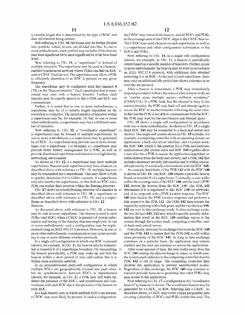
FIG. 1 shows a single wireless cell in which a reader decoder circuit (RDC) and a personal digital key (PDK) are present.
FIG. 2 shows partially overlapping RDC cells. FIG. 3 shows synchronized partially overlapping RDC
cells. FIG. 4 shows a synchronized multi-cell system in accor
dance with one or more embodiments of the present inven tion.
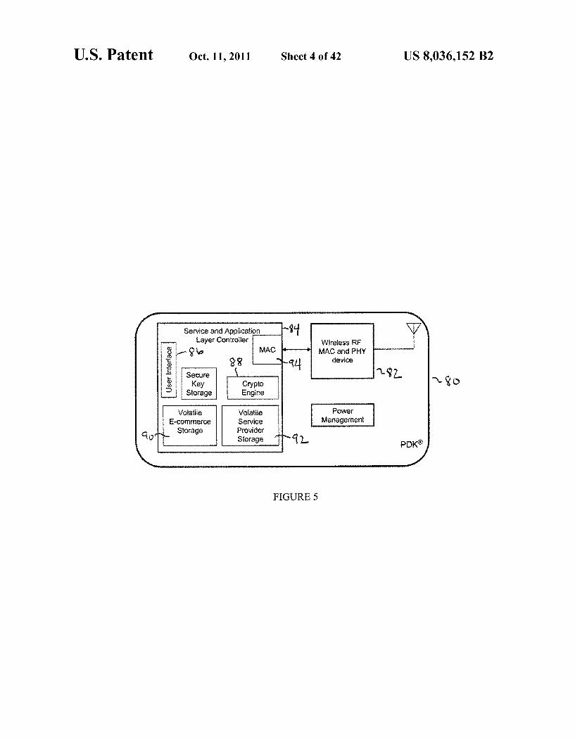
FIG. 5 shows a PDK in accordance with one or more embodiments of the present invention.
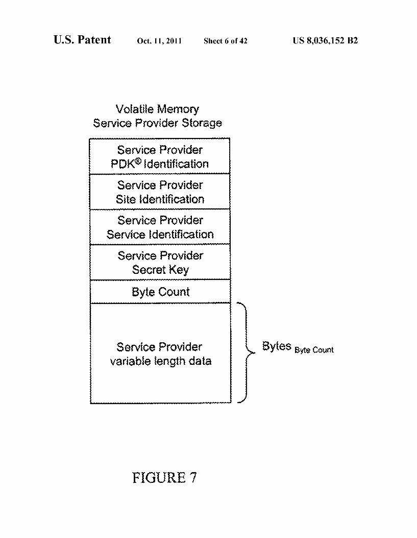
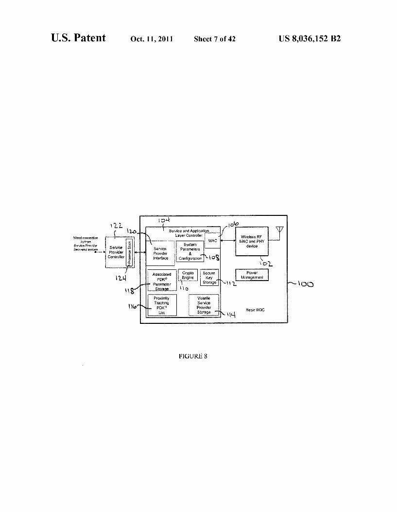
FIG. 6 shows a portion of the PDK shown in FIG. 5. FIG. 7 shows a portion of the PDK shown in FIG. 5. FIG. 8 shows an RDC in accordance with one or more
embodiments of the present invention. FIG. 9 shows an RDC in accordance with one or more
embodiments of the present invention. FIG. 10 shows an arrangement of a timeslot in accordance
with one or more embodiments of the present invention. FIG. 11 shows a superframe in accordance with one or
more embodiments of the present invention. FIG. 12 shows a coordinator Superframe in accordance
with one or more embodiments of the present invention. FIG. 13 shows an overall framing structure in accordance
with one or more embodiments of the present invention. FIG. 14 shows an RDC beacon for use in a single cell
system in accordance with one or more embodiments of the present invention.
FIG. 15 shows a single cell system in accordance with one or more embodiments of the present invention.
FIG.16 shows a PDK-RDC handshake in accordance with one or more embodiments of the present invention.
FIG. 17 shows a coordinator beacon configuration in accordance with one or more embodiments of the present invention.
FIG. 18 shows a PDK transmit timeslot enable operation in accordance with one or more embodiments of the present invention.
FIG. 19 shows a location tracking system configuration in accordance with one or more embodiments of the present invention.
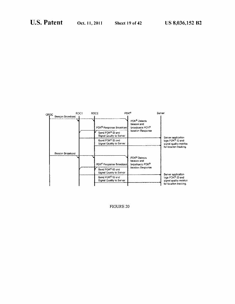
FIG. 20 shows a coordinator RDC (CRDC) location track ing handshake in accordance with one or more embodiments of the present invention.
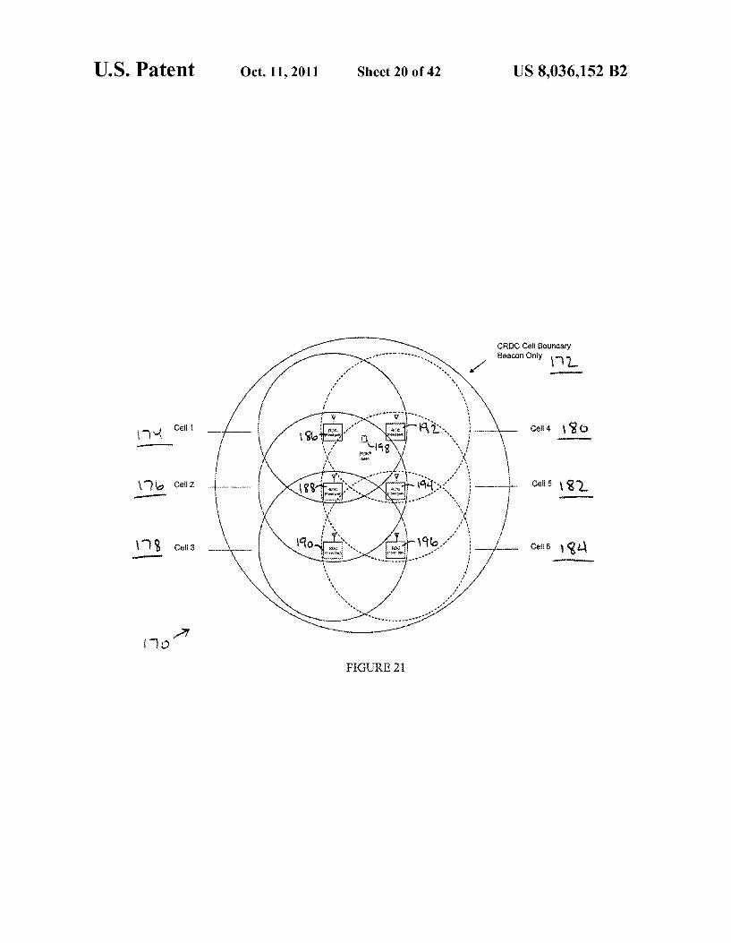
FIG. 21 shows a configuration in which RDCs and PDKs are coordinated withina CRDC cell inaccordance with one or more embodiments of the present invention.
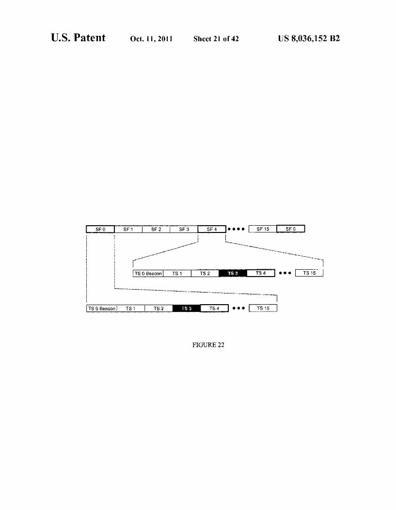
FIG. 22 shows a CRDC framing and PDK timeslot response operation in accordance with one or more embodi ments of the present invention.
FIG. 23 shows a CRDC beacon and PDK response hand shake in accordance with one or more embodiments of the present invention.
FIG. 24 shows a PDK/RDC association in a CRDC cell in accordance with one or more embodiments of the present invention.
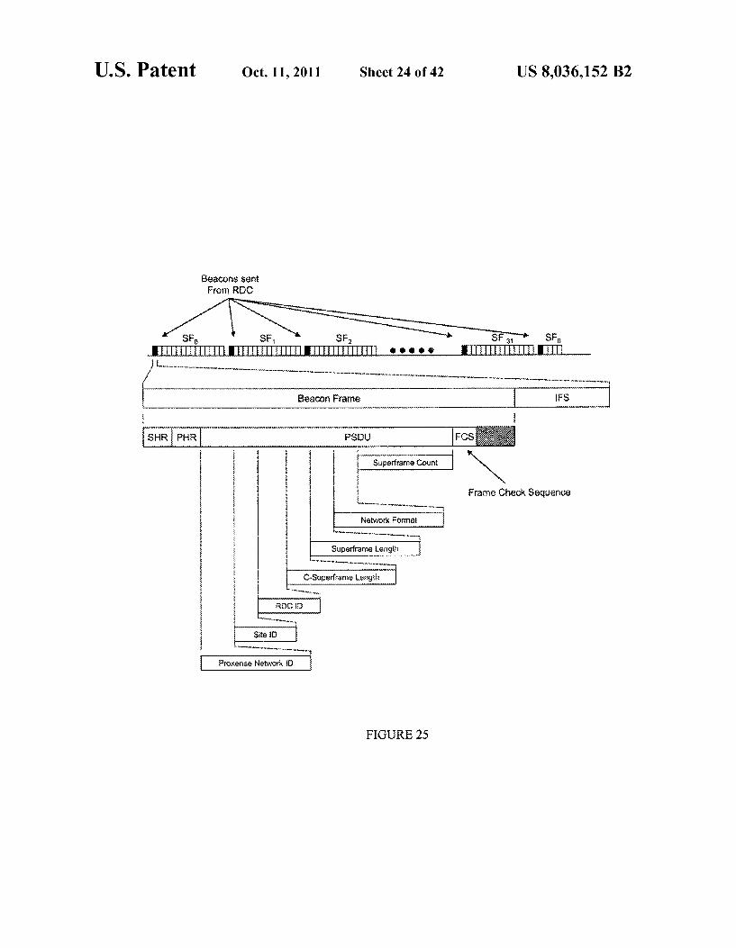
FIG.25 shows an RDC beacontransmission in accordance with one or more embodiments of the present invention.
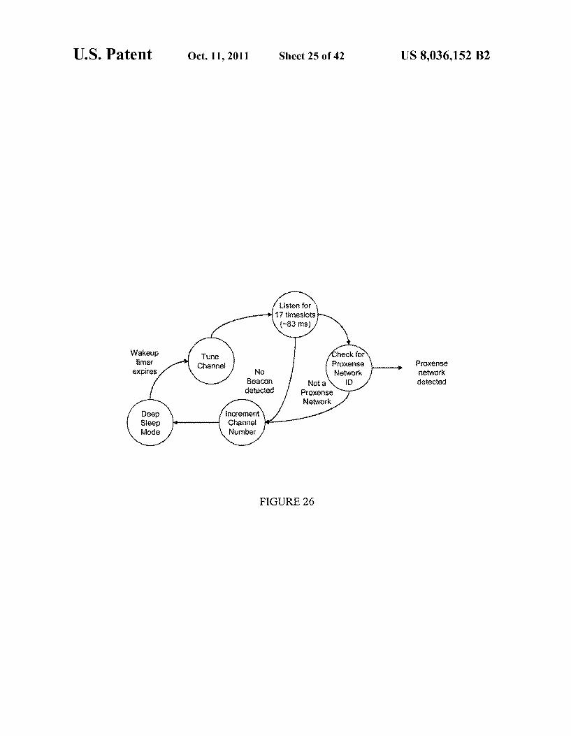
FIG. 26 shows a deep sleep state diagram in accordance with one or more embodiments of the present invention.
FIG. 27 shows an authorization denial handshake opera tion in accordance with one or more embodiments of the present invention.

US 8,036,152 B2 3
FIG.28 shows an authorization grant and association hand shake in accordance with one or more embodiments of the present invention.
FIG. 29 shows a single cell with multiple PDK access in accordance with one or more embodiments of the present invention.
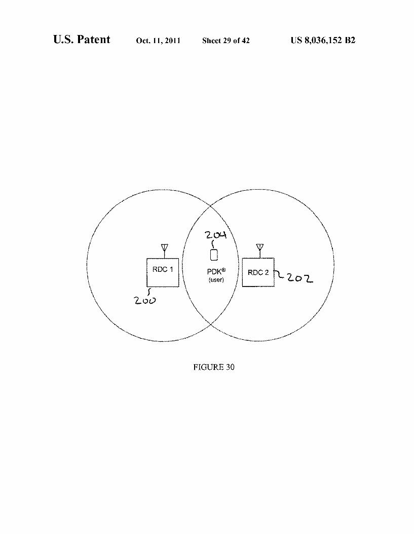
FIG. 30 shows multiple single cell RDCs with cell overlap in accordance with one or more embodiments of the present invention.
FIG.31 shows a floor layout and cell distribution in accor dance with one or more embodiments of the present inven tion.
FIG. 32 shows a gambling table with RDCs in accordance with one or more embodiments of the present invention.
FIG. 33 shows a CRDC beacon to central server flow in accordance with one or more embodiments of the present invention.
FIG.34 shows a CRDC beacon to central server handshake in accordance with one or more embodiments of the present invention.
FIG. 35 shows a configuration of overlapping CRDC cells in accordance with one or more embodiments of the present invention.
FIG. 36 shows a c-beacon handoff for RDC-PDK commu nication in accordance with one or more embodiments of the present invention.
FIG. 37 shows a PDK wakeup and response state flow in accordance with one or more embodiments of the present invention.
FIG.38 shows a configuration of an electronic game with an integrated RDC in accordance with one or more embodi ments of the present invention.
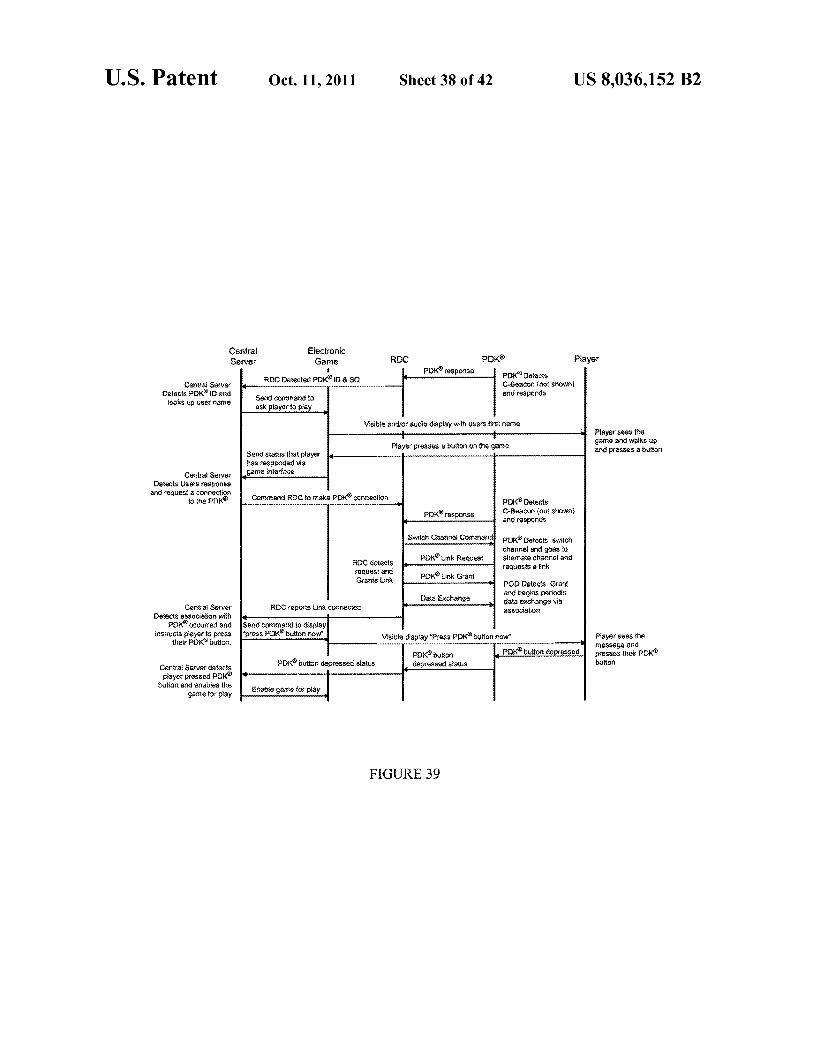
FIG. 39 shows an electronic game player tracking and game enable handshake in accordance with one or more embodiments of the present invention.
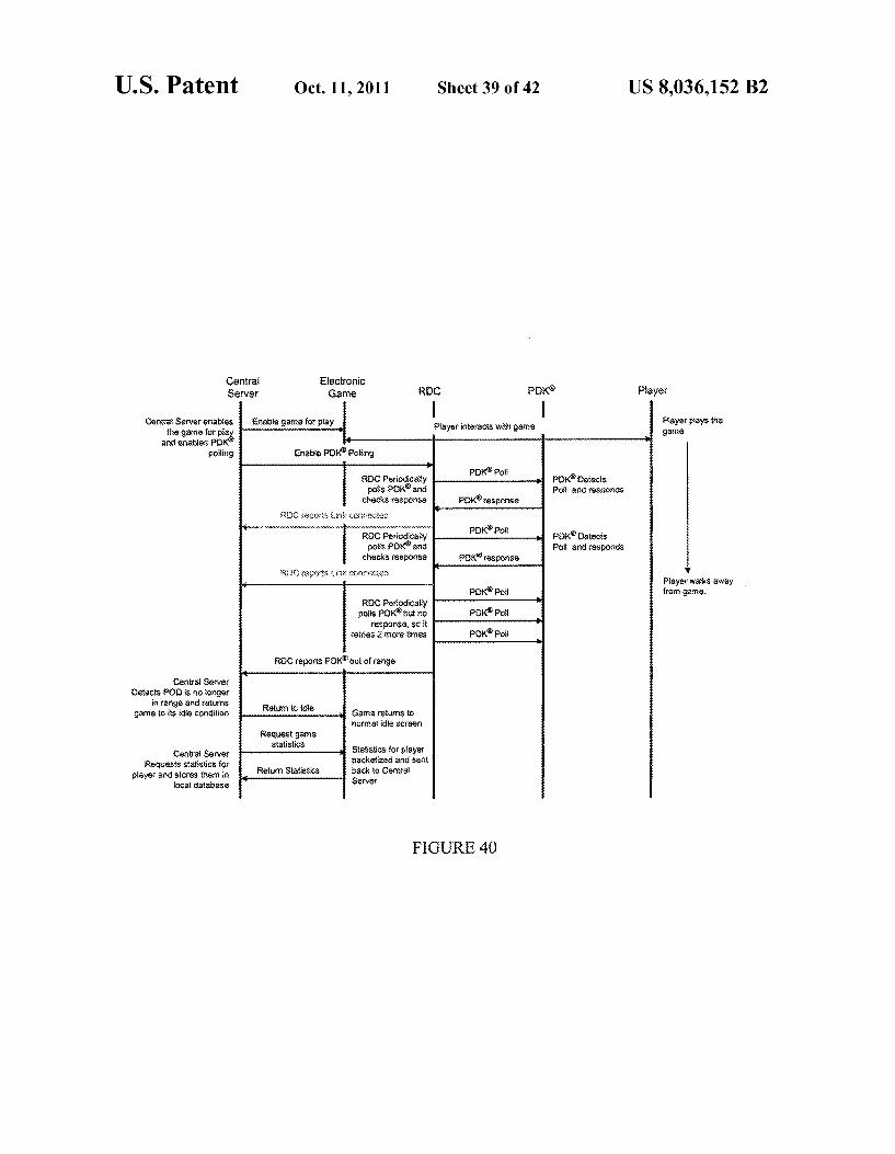
FIG. 40 shows an electronic game player association hand shake in accordance with one or more embodiments of the present invention.
FIG. 41 shows a configuration of an electronic game with an integrated RDC in accordance with one or more embodi ments of the present invention.
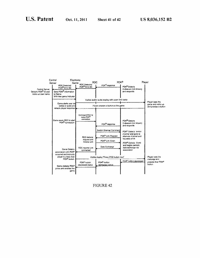
FIG. 42 shows an electronic game player tracking and game enable handshake in accordance with one or more embodiments of the present invention.
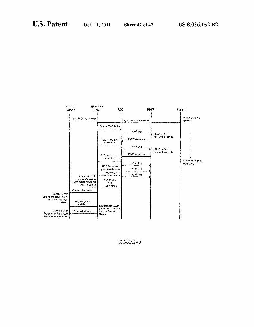
FIG. 43 shows an electronic game player association hand shake in accordance with one or more embodiments of the present invention.
Each of the figures referenced above depict an embodiment of the present invention for purposes of illustration only. Those skilled in the art will readily recognize from the fol lowing description that one or more other embodiments of the structures, methods, and systems illustrated herein may be used without departing from the principles of the present invention.
DETAILED DESCRIPTION
In the following description of embodiments of the present invention, numerous specific details are set forth in order to provide a more thorough understanding of the present inven tion. However, it will be apparent to one skilled in the art that the present invention may be practiced without one or more of these specific details. In other instances, well-known features have not been described in detail to avoid unnecessarily com plicating the description.
In general, embodiments of the present invention relate to a technique for managing power consumption of a client
5
10
15
25
30
35
40
45
50
55
60
65
4 device. Particularly, in one or more embodiments, power consumption of a wireless client device is controlled by caus ing the client device to be in an active mode when a wireless data interaction is required and in a sleep mode at other times. At perhaps a most basic level, one or more embodiments
includes a personal digital key (“PDK) and a reader decoder circuit (“RDC). In general, a PDK is a portable wireless device that may be conveniently carried by an individual to facilitate wireless tracking and/or allow the individual to wirelessly access various applications, assets, and/or Ser vices. As further described in detail below with reference to FIGS. 5-7, a PDK may be any device that (i) may be worn, placed in a pocket, wallet, or purse of a user, or attached to equipment, (ii) has a bi-directional wireless communications transceiver, and (iii) Stores public and/or secret electronic identification numbers, as possibly some set of cryptographic keys. The form factor of the PDK is not limiting, so long as the PDK may be portably, and preferably conveniently and seam lessly, carried by an individual. For example, a PDK may be in the form of a “key fob’ or a card, or in certain embodi ments, a PDF may actually be integrated with or implemented in another device. Such as a watch or mobile computing device (e.g., cellular phone, personal digital assistant (PDA)). An RDC, as used in one or more embodiments, is a device
that can wirelessly interact with a PDK to link the PDK user with various applications, assets, and/or services. The RDC may be a fixed access point serving as a gatekeeper for a PDK requesting access to a particular system. An RDC may be used in various settings and/or applications. For example, an RDC may be physically incorporated into a casino floor itself, an electronic game, a doorway, a pedestrian traffic monitoring point, a personal computer application, an e-commerce device (e.g., an automatic teller machine (ATM)), or any other application requiring a secure transaction or access control.
Further, secure data exchange for various financial and/or retail applications may be facilitated through use of a PDK and RDC in accordance with one or more embodiments. For example, a purchasing system may be implemented whereby a consumer can purchase goods or services using his/her personal “key' (e.g., a PDK) based on the key being in detect able wireless proximity of a reader device (e.g., an RDC). The purchase transaction may then be carried out based on some data exchange between the key and the reader device, where the key stores accessible, and possibly encrypted or encoded, information about the consumer (e.g., name, address, phone number, bank account information, biometric information, credit or debit card information). The validation or authenti cation of the consumer may occur either on the key itself and/or by the reader device. In the case of “on-key valida tion, for example, the reader device may pass some informa tion about the consumer (e.g., a biometric input, such as fingerprint data) to the key, which then matches the data provided by the reader device with permanently stored secure data about the consumer.
Various other applications or uses involving any number of PDK and RDC devices are possible inaccordance with one or more embodiments. Accordingly, while examples of sce narios and applications are described herein for purposes of illustration and clarity, the present invention is not limited to any particular application, Scenario, setting, or use. Single Cell Operation of the RDC and PDK Now referring to FIG. 1, it shows a single cell 10 in which,
at some point in time, an RDC 12 and a PDK14 are present. The RDC 12 may be some fixed device that has a cell radius defined by its wireless coverage boundary. When an indi vidual carrying the PDK14 comes into proximity of the RDC 12 by entering a coverage area of the RDC 12, a wireless

US 8,036,152 B2 5
communications session is initiated between the PDK14 and the RDC 12. If the RDC 12 determines that the PDK14 is authorized to communicate, information between the PDK14 and the RDC 12 may be securely exchanged. Information securely obtained from the user's PDK14 may then be used locally or sent through a back-end communications channel to a central server (not shown). When the transaction com pletes or when the PDK 14 leaves the coverage area of the RDC 12, wireless communication between the RDC 12 and the PDK14 ceases. Thereafter, the RDC 12 may remain idle (i.e., be in a “tracking mode) until a PDKagain enters the cell 10. Unsynchronized Multi-Cell Operation of Multiple RDCs and PDKS Now referring to FIG. 2, in certain implementations, mul
tiple RDC cells 20, 22, 24 may exist in an area. The RDCs in the multiple cells 20, 22, 24 may or may not be aware of each other, but are able to interact with one or more PDKs. The PDKs, in turn, are capable of interacting with the RDCs. As shown in FIG. 2, there are three partially overlapping RDC cells 20, 22, 24. An RDC 26, 28, 30 in cells 20, 22, 24, respectively, is independent and may not be in association with the other RDCs. Although the cells 20, 22, 24 partially overlap, each RDC 26, 28, 30 is capable of wirelessly com municating with any PDK 29, 31 within its cell boundary.
In one or more embodiments, the RDC 26, 28.30 is capable of determining if energy is present on any given wireless channel. The RDC 26, 28, 30 may then determine the best channel to operate on and continue to place an identification marker (or “beacon') out for any PDK29, 31 that enters its cell boundary.
The PDK29, 31 itself may be responsible for locating an RDC 26, 28, 30 by searching through available wireless chan nels, communicating with an RDC 26, 28, 30, and notifying the RDC 26, 28, 30 of its presence. In an implementation where two RDCs can communicate with one another (e.g., RDCs 26, 28 in cells 20, 22 shown in FIG. 2), the RDCs may select different communication frequencies. However, in the case where cells overlap, but each RDC cannot directly com municate with one another (e.g., RDCs 28, 30 in cells 22, 24 shown in FIG. 2), any PDK intending to access an RDC, may have to alert the RDC of possible collisions on the wireless channel on which the RDC is operating. Synchronized Multi-Cell Operation of Multiple RDCs and PDKS
In certain implementations, multiple RDCs may be placed to allow an overlap of cells between each adjacent RDC within a confined area. This permits each RDC to be aware of its Surrounding RDCs, thereby allowing synchronization of each RDC to the other. For example, now referring to FIG. 3, there are shown three partially overlapping RDC cells 40, 42. 44 with RDCs 46, 48, 50. The cell 40, 42, 44 of each respec tive RDC 46, 48,50 overlaps the cell of the adjacent RDC 46, 48, 50. In such a manner, each RDC 46, 48, 50 may initiate wireless communication with an adjacent RDC 46, 48, 50. This begins a negotiation process among the RDCs 46, 48,50 to determine which RDC 46, 48,50 should be the coordinator and on what channel to communicate.
Although any of the RDCs 46, 48, 50 may be the coordi nator, in the example shown in FIG.3, RDC 48 in cell 42 may be a favorable candidate. Its selection permits ubiquitous coverage of the RDCs 46, 48,50 shown in FIG.3, additionally providing multiple transactions and timing alignment through a "daisy chain' whereby RDC 46 synchronizes RDC 48 and RDC 48 synchronizes RDC 50.
Still referring to FIG. 3, each RDC 46, 48, 50 may also share frequency and timeslot information among each other
5
10
15
25
30
35
40
45
50
55
60
65
6 and with one or more PDKs. It is noted that ifa PDK is located at an edge of, for example, cell 40, that PDK may still monitor the other channels that adjacent RDCs 48, 50 are operating on, but may not have access to these RDCs. Thus, in a con figuration such as that shown in FIG.3, a PDK may be forced to consume more energy due to the monitoring of multiple channels. Further, it is noted that as cell density increases, more collisions may begin occurring and/or active commu nication times may increase. Coordinated Multi-Cell Operation Now referring to FIG. 4, it shows an exemplar synchro
nized (or “coordinated') multi-cell system 60 in accordance with one or more embodiments. As will be apparent from the description below, a synchronized multi-cell System may pro vide ubiquitous PDK and RDC synchronization as well as PDK battery conservation within the system 60. Further, in addition to ubiquitous synchronization, channel and fre quency capacity may both be coordinated, thereby reducing collisions while increasing system throughput.
Turning now to FIG. 4 particularly, a coordinator RDC (“CRDC) 62 has ubiquitous coverage of a plurality of cells 64, 66, 68 in the system 60. In one or more embodiments, the CRDC 62 provides beacon transmissions, which can be used to synchronize a plurality of devices within the coverage area 76 of the CRDC 62. In other words, by providing wide-area coverage, a plurality of devices, both RDCs 70, 72, 74 and PDKs (shown, but not labeled in FIG. 4), in the coverage area 76 are able to monitor a wireless transmission beacon broad cast by the CRDC 62 and determine how and when to com municate in a coordinated manner. Further, in one or more embodiments, the CRDC 62 may broadcast additional infor mation including, but not limited to, a beacon transmission rate, framing information, channel information, System iden tification, and/or cluster identification. Moreover, it is noted that although the CRDC 62 may provide timing and certain system related information, RDCs 70, 72, 74 and PDKs may still communicate among themselves. As described above with reference to FIGS. 1-4, there are
at least three different types of devices (or software entities) that may be used, for example, in a synchronized multi-cell system, such as that shown in FIG. 4. A PDK is a trackable device having secure electronic keys and that may be portably carried by a user. An RDC is a device that acts as a gatekeeper controlling access of a PDK to a particular system. A CRDC is a device that is used to synchronize one or more RDCs and PDKs within a particular geographic area formed of either a single cell or multiple cells. A more detailed description of each of these components is now provided below. PDK Now referring to FIG. 5, it shows an example PDK 80 in
accordance with one or more embodiments. Based on a spe cific application or use of the PDK80, the PDK 80 may have different configurations for interacting with the PDK user. For example, the PDK 80 may have no user input mechanism or display, may have a single button input mechanism, may have a multi-button input mechanism, may have a biometric input mechanism, and/or may have an interactive user input mechanism and/or display. As shown in FIG. 5, the PDK 80 has a wireless radio
frequency (RF) media access control (MAC) and physical layer device 82 that facilitates bidirectional communications with external wireless RF devices, such as an RDC (not shown). In one or more embodiments, the wireless RF MAC and physical layer device 82 may communicate according to an IEEE 802.15.4 protocol. However, in one or more other embodiments, the PDK 80 may be capable of communicating according to one or more different wireless protocols.

US 8,036,152 B2 7
The PDK 80 also has a service and application layer con troller 84 that includes a MAC portion 94 that serves as an interface with the wireless RFMAC and physical layer device 82. Further, the service and application layer controller 84 also includes portions that provide specific functions used to protect electronic keys and services of the PDK 80. Further still, the service and application layer controller 84 may Sup port an optional user interface 86, which if implemented, allows user interaction with the PDK 80. A cryptography engine 88 may also be resident on the PDK 80. Now also referring to FIG. 6, it shows a non-volatile
memory storage 90 and a volatile memory storage 92 of the PDK 80. These two devices 90,92 are related to security storage. In one or more embodiments, these devices 90, 92 may be accessible by an RDC (not shown) having the appro priate security algorithms and by private service providers having the correct security information. However, in one or more other embodiments, certain secured data may not be wirelessly communicated at all, in which case, validation or authorization occurs on the PDK 80 itself.
Specifically as to the non-volatile memory storage 90, a public serial number may be used to identify the PDK 80 and allow secure look-up of a secure serial number and a cryp tography key via a remote server (not shown). The Secure serial number may be thought of as being equivalent to, for example, encoded user identification information stored in a magnetic strip of a credit card, whereby such information is not visible to the outside world. The cryptography key may be used to allow decoding of the secure serial number from, for example, an RDC (not shown).
Further, it is noted that in one or more embodiments, the non-volatile memory storage 90 and associated parameter lengths may be dynamically assigned, with overall con straints depending on, for example, available memory in the PDK 8O. Now, specifically as to the volatile memory storage 92, this
area may be used for security and may allow a service pro vider to store a profile containing secret keys and othersecure information, Such as privilege information. A service pro vider identification value may be stored to allow the service provider to easily identify the user. In addition, a service provider service identification value may be stored and used to allow that service provider to access that information. The PDK 80 validates that service provider identification value via the service provider secret key before allowing access to that service provider's profile area in the PDK 80. Further, as shown in FIG. 6, the volatile memory storage 92 may have a number of service provider profiles. Now also referring to FIG. 7, the service provider profile
area may be of a variable length and allow a service provider the flexibility to store various parameters. The length may be determined by a byte count following the service providers secret key in the memory area as shown in FIG. 7. RDC
Next, turning to a more detailed description of an RDC 100 according to one or more embodiments, reference is made below to FIGS. 8 and 9. In general, an RDC 100, as described above, may be fixed and used to allow a PDK access into a particular system (e.g., gaming/casino system, financial insti tution, retail system). The RDC 100 may have different con figurations to Support different types of secure transactions. Some examples of applications and uses of RDCs include, but are not limited to, casino slot machines and gaming consoles, secure entryway control, user/equipment location tracking, personal computers and components thereof (e.g., disk drives), financial institution interactions, and retail purchas ing. In the case of a personal computer, or any computer
10
15
25
30
35
40
45
50
55
60
65
8 system for that matter, a reader device, such as an RDC, may be used to control access to certain data stored in the computer system. Thus, in such embodiments, an RDC 100 may be thought of as providing a form of digital content manage ment.
In certain cases, the RDC 100 effectively acts as a gate keeper allowing authorized individuals access to specific information or transactions. In other cases, because an RDC 100 may use proximity detection for determining if a PDK is within a particular geographical area, the RDC 100 may also be used for tracking one or more PDKs within a given area or network. In still other cases, an RDC 100 may be used for both location tracking and secure transaction purposes.
FIG. 8 shows a type of RDC 100 that uses a single wireless RF MAC and physical layer device 102. In RDC 100, com munications are passed through the single wireless RF MAC and physical layer device 102. The single wireless RF MAC and physical layer device 102 facilitates bidirectional com munication with one or more external RF wireless devices, such as a PDK (not shown). Thus, the single wireless RF MAC and physical layer device 102 may communicate with both PDKs according to assigned time slots (further described below) and one or more CRDCs (described in further detail below). Further, it is noted that in one or more embodiments, the single wireless RFMAC and physical layer device 102 may wirelessly communicate according to an IEEE 802.15.4 protocol. However, in one or more other embodiments, the RDC 100 may be capable of communicat ing according to one or more different wireless protocols. The RDC 100 also has a service and application layer
controller 104. The service and application layer controller 104 has a MAC portion 106 specific to a wireless protocol of the RDC 100. The service and application layer controller 104 may further provide functions related to associating and tracking PDKs (not shown), as well as providing information back to a service provider. The service and application layer controller 104 includes
system parameters and configuration information 108 that may be used to identify the RDC 100 and define how the RDC 100 operates within a given environment. Further, the system parameters and configuration information 108 may define how the RF link is timeslotted and/or how RF frequencies are used in the system. In one or more embodiments, these values may be optimized to reduce power consumption within one or more PDKs (not shown).
Still referring to the RDC 100 shown in FIG. 8, a cryptog raphy engine 110 may also be present. One or more of various storage elements may also exist in the service and application layer controller 104. A secure key storage area 112 may be programmed to define public, secret, and/or cryptography keys for the RDC 100.
Further, in one or more embodiments, the service and application layer controller 104 may have additional memory areas, one or more of which may dynamically change depen dent on system changes and wireless PDK connections. A volatile service provider storage 114 may allow a service provider to store semi-static information related to a specific PDK (not shown) or group of PDKs (not shown) for real-time access for those devices. An example might relate to a hotel room door lock. With a hotel room door, service provider information related to a PDK may be stored in the RDC. When a user comes within proximity of the door, the door could unlock. Thus, in this example, the RDC is not required to interface with a back-end server in real-time, thereby reducing bandwidth consumption to the back-end server, while allowing the user immediate access. Moreover, in one or more embodiments, the RDC may have a connection to a

US 8,036,152 B2
network or other infrastructure for receiving control signals as to which PDKs should be allowed to unlock the door. The service and application layer controller 104 may also
have a proximity tracking PDK list 116 that includes PDK identity information, signal quality metrics, and/or time stamps for each PDK (not shown) that is in proximity of the RDC 100. Such information may be used in the RDC 100 to perform an operation and/or may be relayed to a back-end server when, for example, location tracking is desired.
Still referring to FIG. 8, the service and application layer controller 104 may also have an associated PDK parameter storage 118. The associated PDK parameter storage 118 may contain a list of one or more PDKs (not shown) actively performing transactions with the RDC 100. It is noted that in one or more embodiments, although such transactions are performed with the RDC 100, the actual processing result of the RDC 100 to/from PDK transaction may be passed to a back-end server for further processing. A service provider interface 120 may allow both control
and query of the RDC 100. The service providerinterface 120 may further provide the transport for keys from a PDK (not shown). In one or more embodiments, the service provider interface 120 may use a universal asynchronous transmitter receiver (UART) interface and may allow some level of con trol and Status of the RDC 100. An external service provider controller 122 may be
attached to the service provider interface 120 with a system stack 124 residing in the external service provider controller 122. The system stack 124 may allow a third party to easily interface with the RDC 100, possibly requiring function calls to the system stack 124. Further, the external service provider controller 122 may provide translation of data. It is still fur ther noted that the external service provider controller 122 and the RDC 100 may reside on the same physical component (e.g., circuit board). Now referring to FIG.9, it shows another type of RDC130,
which has an additional wireless RFMAC and physical layer device 132. In this configuration, components having like reference numbers as those reference numbers in FIG. 8 function identically or similarly to the corresponding compo nents in FIG.8. The additional wireless RF MAC and physi cal layer device 132 may be used to maintain synchronization with a CRDC (not shown) and pass networking related infor mation, while the other wireless RF MAC and physical layer device 102 may be used to communicate with one or more PDKs (not shown) within a cell of the RDC 130. Further, the service and application layer controller 104 may have an additional MAC portion 134 to interface with the additional wireless RF MAC and physical layer device 132.
Still referring to the RDC 130, the use of dual wireless transceivers 102,132 may allow for increased throughput and efficient use of the RF spectrum available to the system. Thus, in other words, these multiple wireless links allow simulta neous reception of data from client devices (e.g., PDKs) and of CRDC timing information on separate channels, thereby eliminating the need for back-channel synchronization of the network. Further, the multiple wireless links may allow for the simultaneous proximity sensing of multiple client devices (e.g., PDKs) in a “tracking mode, along with the association of a client device with one particular cell for wireless appli cation (e.g., secure transaction) purposes. For example, an RDC serving as a wireless player tracking device on a casino floor may, while keeping track of multiple transient players entering and leaving the Zone of coverage of that particular tracking device, invite a particular player to begin a gaming session. This session may also include the exchange of player information with, for example, both the game and its back
10
15
25
30
35
40
45
50
55
60
65
10 end server to allow credit for games played and money spent. In another scenario, the system may facilitate another entire Suite of applications. Such as, for example, unlocking a hotel room door, while simultaneously keeping track of unrelated client devices coming and going within its coverage range. CRDC
Next, turning to a more detailed description of a CRDC according to one or more embodiments, a CRDC may, for example, be an RDC of either of the types described above with reference to FIGS. 8 and 9. At least one difference, however, between a CRDC and an RDC is that the CRDC has increased RF power output, or more generally, casts abroader range of wireless coverage. Another difference is that, in one or more embodiments, a CRDC may not communicate bi directionally with a PDK, whereas an RDC of the types described above with reference to FIGS. 8 and 9 may. More over, a CRDC may be capable of communicating with another CRDC, and may also be capable of communicating with an RDC. It is noted that CRDC-CRDC communication may allow for frame synchronization and frequency planning without requiring a wired connection between the CRDCs. The same may be true for CRDC-RDC communications. In certain implementations, it may occur that CRDC cell bound aries do not overlap, and thus, the corresponding CRDCs may not be able to directly communicate with another. In this case, an RDC that is between the cells may communicate with both CRDCs and act as a communication bridge to pass frequency and other control information in an effort to coordinate the system.
Still describing the general application and use of a CRDC in accordance with one or more embodiments, the CRDC may serve as a stand-alone wireless beacon that may be used to coordinate the timing and activities of individual, physi cally separated wireless providers (e.g., RDCs) with defined coverage areas, along with their clients (e.g., PDKs) in an autonomous, wireless proximity sensing and data transfer network. A CRDC may also be used to propagate system wide information (e.g., periodic changes in cryptographic keys), thereby relieving traffic otherwise loading a wired back-end network linking individual cells to the back-end system. Thus, the CRDC may act as a system-wide master clock across multiple cells that may not be close enough to synchronize with each other directly without a wired connec tion. Wireless Protocol As described above, a system in accordance with one or
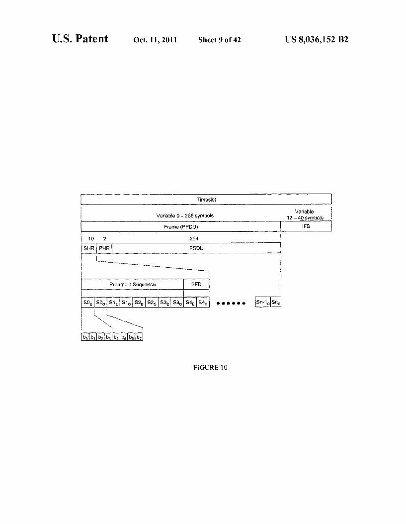
more embodiments may rely, or at least partly be based, on an IEEE 802.15.4 protocol. In relation to a protocol usable in one or more embodiments, a “timeslot is defined as a period of time that information is communicated between two devices. FIG. 10 shows an example of portions of a timeslot in accor dance with one or more embodiments. The timeslot is divided into a frame (or physical packet data unit (PPDU)) and inter frame spacing (IFS). The frame includes synchronization information and carries the payload of data. The IFS allows time for a receiving end unit to process the data in the frame and transmitter turn-around time. Both the PPDU and the IFS may be variable in length as determined by an amount of data carried in the frame. The frame is broken down into a sync header (SHR), a
physical header (PHR), and a physical service data unit (PSDU). The SHR may contain a preamble sequence and start-of-frame delimiter (SFD) that allows a receiving device to acquire the RF signal and synchronize to the frame. The PSDU may then be used to carry both 802.15.4MAC and user data information. Further, it is noted that the PSDU may be of
US 8,036,152 B2 11
a variable length that is determined by the type of MAC and data information being carried.
Still referring to FIG. 10, the frame may be further divided into symbols, which, in turn, are divided into bits. In one or more embodiments, each symbol may includes 4 bits that are sent least significant bit to most significant bit at the base band level. Now referring to FIG. 11, a “superframe' is formed of
multiple timeslots. The Superframe may be used in a beacon enabled synchronous network where PDKs can find an RDC and/or CRDC fixed device. The Superframe may allow a PDK to efficiently determine if an RDC is present on any given frequency. The Superframe may be configured such that timeslot 0
(TS) is the “beacon timeslot. Each superframe that is trans mitted may start with a beacon timeslot. Further, each timeslot may be equally spaced so that a PDK and RDC can communicate.
Further, it is noted that in one or more embodiments, a Superframe may be of a variable length dependent on the resolution to a timeslot. The initial number of timeslots within a Superframe may be, for example, 16; but, in one or more other embodiments, a Superframe may have a different num ber of timeslots. Now referring to FIG. 12, a “coordinator superframe'
(c-Superframe) may be formed of multiple Superframes. In one or more embodiments, a c-superframe may be generated by a CRDC. A c-superframe may provide one or more advan tages over a Superframe. For example, a c-Superframe may provide better battery management for a PDK, as well as provide distributed Superframe and timeslots in a high density networking environment. As shown in FIG. 12, a c-superframe may have multiple
Superframes. Because each Superframe may have a beacon, as described above with reference to FIG. 11, multiple beacons may be transmitted per c-superframe. This may allow a PDK to quickly determine if it is within a system. A c-Superframe may also number the superframes, so that both an RDC and a PDK can realize their position within the framing structure.
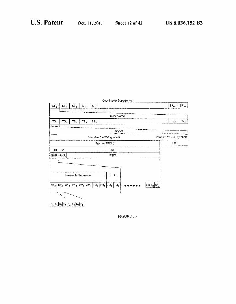
FIG. 13 shows an overall framing structure of a timeslot as described above with reference to FIG. 10, a superframe as described above with reference to FIG. 11, and a c-super frame as described above with reference to FIG. 12. Beacons As discussed above with reference to FIG. 11, a beacon
may be sent in every superframe. The beacon is used to alert PDKs (and RDCs when a CRDC is present) of system infor mation and timing of the framing structure employed. In one or more embodiments, such a configuration may be imple mented using an IEEE 802.15.4 protocol. However, in one or more other embodiments, communication may occuraccord ing to one or more different wireless protocols.
In a single cell configuration in which one RDC is present (shown, for example, in FIG. 1), the beacon may be transmit ted in timeslot 0 of a superframe boundary. By transmitting the beacon periodically, a PDK may wake up and find the beacon within a short period of time and realize that it is within some particular network.
In an unsynchronized multi-cell configuration in which multiple RDCs are geographically located near each other, but no synchronization between RDCs is implemented (shown, for example, in FIG. 2), a PDK may still wake up, detect the presence of the RDCs, and synchronize and com municate with each RDC due to the presence of the beacon on each RDC.
In a high density area in which multiple RDCs are present, a CRDC may most likely be present. In Such a configuration,
10
15
25
30
35
40
45
50
55
60
65
12 the CRDC may transmit the beacon, and all RDCs and PDKs in the coverage area of the CRDC align to the CRDC beacon. The CRDC may send a beacon on each superframe, as well as a c-superframe and other configuration information to the RDCs and PDKs. Now referring to FIG. 14, in a single cell configuration
(shown, for example, in FIG. 1), a beacon is periodically output based on a specific number of timeslots. Further, in one or more embodiments, the beacon may be used in accordance an IEEE 802.15.4 protocol, with additional data attached indicating it is an RDC. At the end of each superframe, there may exist an additional idle period that allows tolerance in an over-the-air protocol.
After a beacon is transmitted, a PDK may immediately respond provided it follows the rules of what is know in the art as “carrier sense multiple access—collision avoidance' (CSMA-CA). If a PDK finds that the channel is busy in the current timeslot, the PDK may back-off and attempt again to access the RDC in another timeslot following the same rules. In the case the PDK is notable to communicate with the RDC, the PDK may wait for the next beacon and attempt again.
FIG. 15 shows a single cell configuration in accordance with one or more embodiments. As shown in FIG. 15, a single fixed RDC 140 may be connected to a back-end server (not shown). The single cell system shown in FIG. 15 includes, for example: a computing controller with an operating system, an application, a back-end server interface, and a system stack; the RDC 140, which is the gateway for a PDK and performs authorization (the system stack and RDC 140 together allow a user who has a PDK to access the application dependent on authorization from the back-end server); and a PDK142 that includes necessary security information and is within reason able proximity to wirelessly communicate with the RDC 140. An example handshake of the PDK142 with the RDC 140
is shown in FIG. 16. The RDC 140 outputs a periodic beacon based on timeslot 0 of a superframe. Eventually, a user walks within the coverage area of the RDC 140, and the user's PDK 142 detects the beacon from the RDC 140. The PDK 142 determines if it is registered to this RDC 140 (or network), and, if so, responds with a PDK location response. The RDC 140 then detects the PDK location response and performs a link request to the PDK142. The PDK142 then accepts the request by replying with a link grant, and the two devices 140, 142 are now in data exchange mode. In data exchange mode, the two devices 140,142 may transfer specific security infor mation that result in the RDC 140 enabling access to the system through the system stack, computing controller, and/ or back-end central server.
Periodically, data may be exchanged between the RDC 140 and the PDK 142 to ensure that the PDK 142 is still within close proximity of the RDC 140. As long as data exchange continues on a periodic basis, the application may remain enabled and the user can continue to access the application.
After some amount of time, the user walks away from the RDC 140 causing the data exchange to cease, in which case, the system stack indicates to the computing controller that the PDK 142 is out of range. The computing controller then disables the application to prevent unauthorized access. Regardless of data exchange, the RDC 140 may continue to transmit periodic beacons to guarantee that other PDKs may gain access to the application. Now referring to FIG. 17, a configuration of a “coordinator
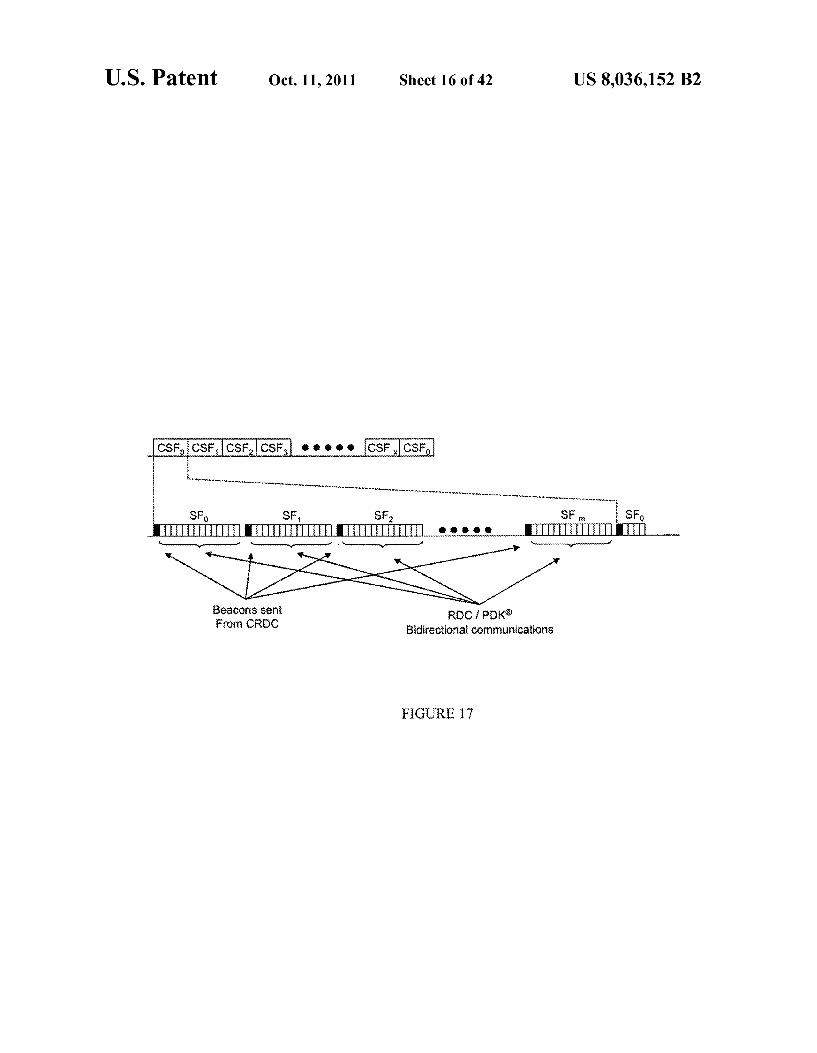
beacon' (c-beacon) is shown. The coordinator beacon may be generated by a CRDC, or RDC behaving like a CRDC. As described above, a CRDC may cover a large geographic area covering a plurality of RDCs and PDKs within that area. The
US 8,036,152 B2 13
c-beacon may be a standard beacon sent in the first timeslot of each superframe as shown in FIG. 17.
Ac-beacon, in accordance with one or more embodiments, may have properties that are different than those associated with an IEEE 802.15.4 standard beacon. For example, the standard c-beacon carries a field indicating the beacon is a c-beacon. Further, a c-beacon, in normal operation, is a uni directional transmission from a CRDC. Further still, a c-bea con may contain other c-beacon related information: number of slots in a Superframe; number of Superframes in a c-super frame; the channels on which adjacent CRDCs operate; cur rent Superframe number, current c-superframe number, site ID: CRDC ID; PDK superframe mask; and PDK timeslot mask.
Further, it is noted that while beacons may be transmitted from a CRDC on timeslot 0 of each superframe, remaining timeslots of a Superframe may be left open for unsynchro nized communications between PDKs and RDCs. The term "unsynchronized' is used to describe communications between the PDKs and the RDCs because the RDC and PDK share a common CRDC beacon, but the PDK may not get synchronized directly to an RDC beacon. In this manner, the PDK and RDC may appear to represent a peer-to-peer net work.
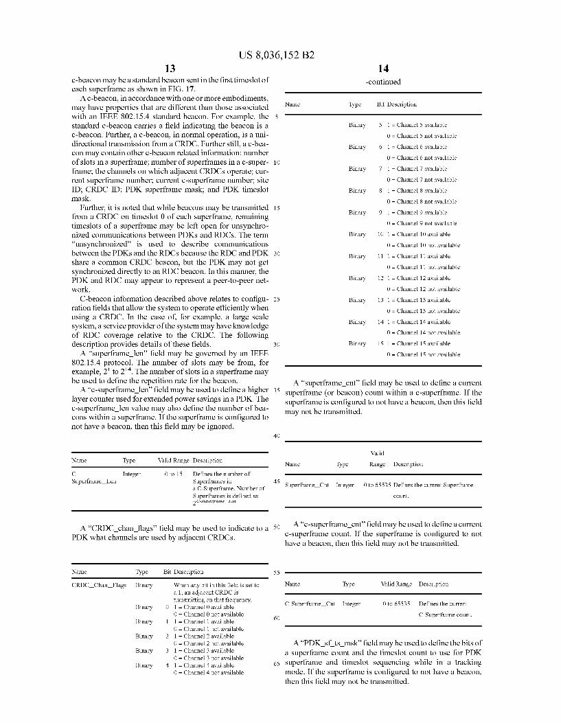
C-beacon information described above relates to configu ration fields that allow the system to operate efficiently when using a CRDC. In the case of for example, a large scale system, a service provider of the system may have knowledge of RDC coverage relative to the CRDC. The following description provides details of these fields. A “superframe len” field may be governed by an IEEE
802.15.4 protocol. The number of slots may be from, for example, 2 to 2''. The number of slots in a superframe may be used to define the repetition rate for the beacon. A “c-superframe len” field may be used to define a higher
layer counter used for extended power savings in a PDK. The c-Superframe len value may also define the number of bea cons within a Superframe. If the Superframe is configured to not have a beacon, then this field may be ignored.
Name Valid Range Description Type
C Superframe Len
O to 15 Defines the number of Superframes in a C-Superframe. Number of Superframes is defined as 2C-Superframe Len
Integer
A “CRDC chan flags' field may be used to indicate to a PDK what channels are used by adjacent CRDCs.
Name Type Bit Description
CRDC Chan Flags Binary When any bit in this field is set to a 1, an adjacent CRDC is transmitting on that frequency.
Binary O 1 = Channel O available O = Channel O not available
Binary 1 1 = Channel 1 available O = Channel 1 not available
Binary 2 1 = Channel 2 available O = Channel 2 not available
Binary 3 1 = Channel 3 available O = Channel 3 not available
Binary 4 1 = Channel 4 available O = Channel 4 not available
10
15
25
30
35
40
45
50
55
60
65
14 -continued
Name Type Bit Description
Binary 5 1 = Channel 5 available
O = Channel 5 not available
Binary 6 1 = Channel 6 available
O = Channel 6 not available
Binary 7 1 = Channel 7 available
O = Channel 7 not available
Binary 8 1 = Channel 8 available
O = Channel 8 not available
Binary 9 1 = Channel 9 available
O = Channel 9 not available
Binary O 1 = Channel 10 available
O = Channel 10 not available
Binary 1 1 = Channel 11 available
O = Channel 11 not available
Binary 2 1 = Channel 12 available
O = Channel 12 not available
Binary 3 1 = Channel 13 available
O = Channel 13 not available
Binary 4 1 = Channel 14 available
O = Channel 14 not available
Binary 5 1 = Channel 15 available
O = Channel 15 not available
A “superframe cnt field may be used to define a current Superframe (or beacon) count within a c-superframe. If the Superframe is configured to not have a beacon, then this field may not be transmitted.
Walid
Name Type Range Description
Superframe Cnt Integer 0 to 65535 Defines the current Superframe count.
A “c-superframe cnt field may be used to define a current c-Superframe count. If the Superframe is configured to not have a beacon, then this field may not be transmitted.
Name Valid Range Description Type
C-Superframe Cnt Integer O to 65535 Defines the current
C-Superframe count.
A“PDK Sf ts msk” field may be used to define the bits of a superframe count and the timeslot count to use for PDK Superframe and timeslot sequencing while in a tracking mode. If the Superframe is configured to not have a beacon, then this field may not be transmitted.

US 8,036,152 B2 15
Name Valid Range Description Type
PDK (R) SF TS Msk
16
Defines which bits are to be used for determining PDK (R) Superframes and timeslots to communicate with an RDC during location tracking.
OOOOOOOOOOOOO to 1 = enable bit
1111111111111 O = mask bit OOO to 111
Superframe Mask Binary
Timeslot Mask Binary 1 = enable bit O = mask bit
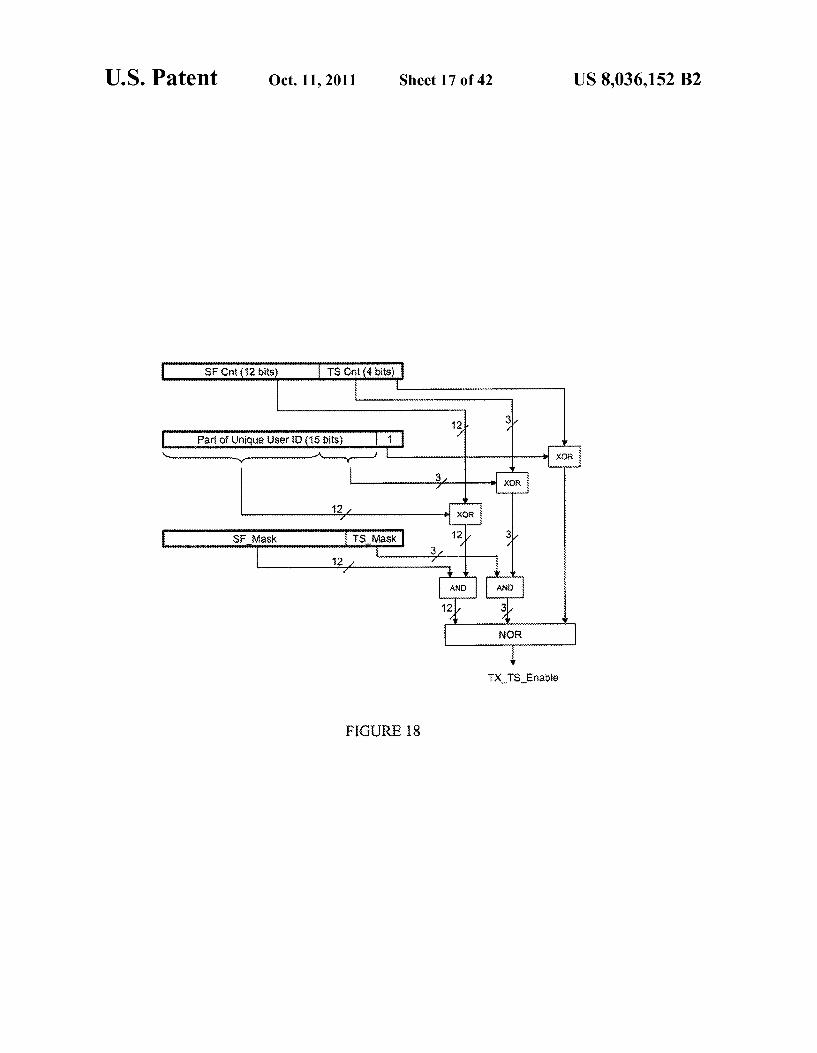
The PDK Sf tS msk value may be used in conjunction with a portion of the service provider unique PDK identifica tion value and may be used to determine the exact Superframe and timeslot the PDK is permitted to transmit a location identifier back to the RDCs. The necessary logic and variables required to perform this operation are illustrated in FIG. 18.
Further, in one or more embodiments, to set the mask value of a particular PDK, a “set pdk msk val' function may be used. The mask may be used over the Superframe and timeslot counts and service provider's PDKID to determine the super frame and timeslot the PDK is active on in the framing struc ture. In other words, the set pdk msk Val function may be used to set a mask for the PDK in an effort to establish at what times the PDK can communicate with an RDC. The function may return a pass or fail indication to indicate whether the mask has been Successfully set. Conversely, to obtain the mask value being used by a particular PDK, a 'get pdk m sk val” function may be used to retrieve the current PDK Superframe and timeslot mask parameters.
Using, for example, the masking approach described above, individual client devices (e.g., PDKs) within a given cell (e.g., an RDC's wireless coverage area) may be addressed via real-time re-provisioning on command. Thus, in other words, by reserving time slots for both client device trans mission and reception (based on masks established by the network), client transmission and reception time slots may be efficiently coordinated to reduce collision likelihood and allow for tiered client access, assignment of specific classes, and/or targeting an individual user for preferential, non-con tended system access. Further, in one or more embodiments, bit masks may be changed to include or exclude specific users (or classes of users). Still further, in one or more embodi ments, bit masks may be changed to dynamically alter access to the network by users or classes of users as traffic load on the network changes. Moreover, it is noted that once a specific client exits the network, previously reserved time slots of that client may be reassigned to one or more other client devices in the network.
To provide an example, there may be multiple client devices (e.g., PDKs) in proximity of a particular fixed reader device (e.g., an RDC). Each of these client devices, other than providing a location response, may request Some data exchange with the reader device in order carry out a secure transaction. In an effort to reduce collision and coordinate the time slots that each client device “talks with the reader device, a mask may be communicated to each client device to set the times at which the client device is to communicate with the reader device. Further, certain ones of the client devices may be afforded some level of priority, in which case the masks would be set accordingly. For example, masks may be set according to a class of a user of a PDK or to a class of the PDK itself. To facilitate such differentiation, priority level or tier level data may be present in an RDC or CRDC to be used
15
25
30
35
40
45
50
55
60
65
Defines the Superframe mask
Defines the Timeslot mask
when setting a mask for a particular client device or group thereof. Thus, in Such a manner, there is provided a technique for dynamic real-time tiered client access. Moreover, it is noted that in one or more embodiments, a CSMA-CA mecha nism may be implemented as a backup approach to facilitate data exchange.
Further, in one or more embodiments, utilization of a tiered access system to transfer and receive data to/from a specific user or client device anywhere within a wireless network may allow for simultaneously operating network-wide two-way communications without altering the network. Thus, in other words, although one or more embodiments relate to an autonomous wireless proximity sensing and data transfer net work, Such a network may be used to notify, page, or transfer data possibly unrelated to one or more of the applications which a majority of the client devices on the network are using (or typically use) (such applications being for the pur poses of, for example, tracking, access control, and/or digital rights management). In another example, a network device may be able to associate a PDK ID to a particular user and then provide massaging capability based on the identity of the user. Thus, in this case, one or more embodiments may be combined with tiering to provide multiple messaging levels for different users.
The ability to assign tiers to the network may also enable low latency responses from targeted client devices. Accord ingly, by integrating features into the client device that may take advantage of a two-way network capability, a system in accordance with one or more embodiments may allow for the simultaneous communication and control of external devices via real-time client command along with a general purpose low data rate two-way network.
Continuing with the description ofc-beacon information in accordance with one or more embodiments, a “site ID' field may carry a value that each CRDC transmits to all PDKs and RDCs within a coverage area of the CRDC. The site ID value allows a PDK to determine if it can access the current site or if it needs to request permissions to access the site's network.
Walid Name Type Range Description
Site ID Integer O to 65535 Defines the current sites ID.
A “CRDC ID field may carry a value that each CRDC transmits to all PDKs and RDCs within a coverage area of the CRDC. The CRDC ID may be used, for example, for geo graphical reference.
US 8,036,152 B2
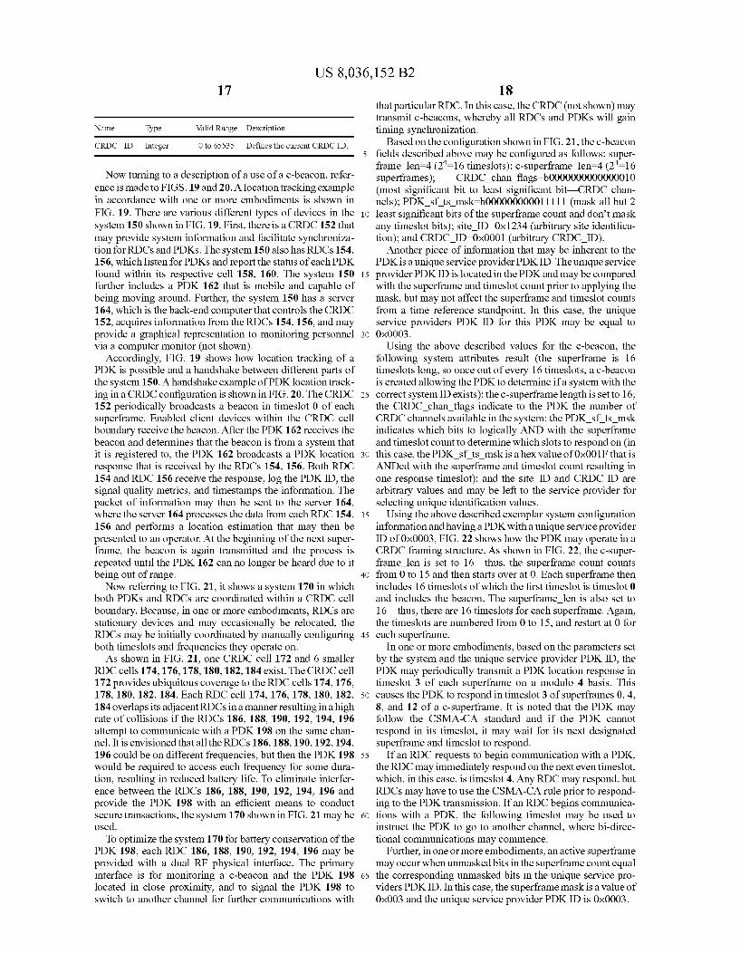
Name Type Valid Range Description
CRDC ID Integer O to 65535 Defines the current CRDC ID.
Now turning to a description of a use of a c-beacon, refer ence is made to FIGS. 19 and 20. A location tracking example in accordance with one or more embodiments is shown in FIG. 19. There are various different types of devices in the system 150 shown in FIG. 19. First, there is a CRDC 152 that may provide system information and facilitate synchroniza tion for RDCs and PDKs. The system 150 also has RDCs 154, 156, which listen for PDKs and report the status of each PDK found within its respective cell 158, 160. The system 150 further includes a PDK 162 that is mobile and capable of being moving around. Further, the system 150 has a server 164, which is the back-end computer that controls the CRDC 152, acquires information from the RDCs 154, 156, and may provide a graphical representation to monitoring personnel via a computer monitor (not shown).
Accordingly, FIG. 19 shows how location tracking of a PDK is possible and a handshake between different parts of the system 150. A handshake example of PDK location track ing in a CRDC configuration is shown in FIG. 20. The CRDC 152 periodically broadcasts a beacon in timeslot 0 of each superframe. Enabled client devices within the CRDC cell boundary receive the beacon. After the PDK162 receives the beacon and determines that the beacon is from a system that it is registered to, the PDK 162 broadcasts a PDK location response that is received by the RDCs 154, 156. Both RDC 154 and RDC 156 receive the response, log the PDKID, the signal quality metrics, and timestamps the information. The packet of information may then be sent to the server 164, where the server 164 processes the data from each RDC 154, 156 and performs a location estimation that may then be presented to an operator. At the beginning of the next Super frame, the beacon is again transmitted and the process is repeated until the PDK 162 can no longer be heard due to it being out of range. Now referring to FIG. 21, it shows a system 170 in which
both PDKs and RDCs are coordinated within a CRDC cell boundary. Because, in one or more embodiments, RDCs are stationary devices and may occasionally be relocated, the RDCs may be initially coordinated by manually configuring both timeslots and frequencies they operate on. As shown in FIG. 21, one CRDC cell 172 and 6 smaller
RDC cells 174, 176, 178, 180,182, 184 exist. The CRDC cell 172 provides ubiquitous coverage to the RDC cells 174, 176, 178, 180, 182, 184. Each RDC cell 174, 176, 178, 180, 182, 184 overlaps its adjacent RDCs in a manner resulting in a high rate of collisions if the RDCs 186, 188, 190, 192, 194, 196 attempt to communicate with a PDK 198 on the same chan nel. It is envisioned that all the RDCs 186,188, 190,192,194, 196 could be on different frequencies, but then the PDK 198 would be required to access each frequency for some dura tion, resulting in reduced battery life. To eliminate interfer ence between the RDCs 186, 188, 190, 192, 194, 196 and provide the PDK 198 with an efficient means to conduct secure transactions, the system 170 shown in FIG. 21 may be used.
To optimize the system 170 for battery conservation of the PDK 198, each RDC 186, 188, 190, 192, 194, 196 may be provided with a dual RF physical interface. The primary interface is for monitoring a c-beacon and the PDK 198 located in close proximity, and to signal the PDK 198 to switch to another channel for further communications with
10
15
25
30
35
40
45
50
55
60
65
18 that particular RDC. In this case, the CRDC (not shown) may transmit c-beacons, whereby all RDCs and PDKs will gain timing synchronization.
Based on the configuration shown in FIG. 21, the c-beacon fields described above may be configured as follows: super frame len=4 (2=16 timeslots); c-superframe len–4 (2=16 Superframes); CRDC chan flags=b0000000000000010 (most significant bit to least significant bit CRDC chan nels): PDK sf tis msk=b000000000011111 (mask all but 2 least significant bits of the Superframe count and don’t mask any timeslot bits); site ID=0x1234 (arbitrary site identifica tion); and CRDC ID–0x0001 (arbitrary CRDC ID).
Another piece of information that may be inherent to the PDK is a unique service provider PDKID. The unique service provider PDKID is located in the PDK and may be compared with the Superframe and timeslot count prior to applying the mask, but may not affect the Superframe and timeslot counts from a time reference standpoint. In this case, the unique service providers PDK ID for this PDK may be equal to OXOOO3.
Using the above described values for the c-beacon, the following system attributes result (the superframe is 16 timeslots long, so once out of every 16 timeslots, a c-beacon is created allowing the PDK to determine if a system with the correct systemID exists): the c-Superframe length is set to 16: the CRDC chan flags indicate to the PDK the number of CRDC channels available in the system; the PDK Sf tS msk indicates which bits to logically AND with the superframe and timeslot count to determine which slots to respond on (in this case, the PDK Sf ts msk is a hex value of 0x001F that is ANDed with the superframe and timeslot count resulting in one response timeslot); and the site ID and CRDC ID are arbitrary values and may be left to the service provider for selecting unique identification values.
Using the above described exemplar system configuration information and having a PDK with a unique service provider ID of 0x0003, FIG.22 shows how the PDK may operate in a CRDC framing structure. As shown in FIG. 22, the c-super frame len is set to 16—thus, the Superframe count counts from 0 to 15 and then starts over at 0. Each superframe then includes 16 timeslots of which the first timeslot is timeslot 0 and includes the beacon. The Superframe len is also set to 16—thus, there are 16 timeslots for each Superframe. Again, the timeslots are numbered from 0 to 15, and restart at 0 for each Superframe.
In one or more embodiments, based on the parameters set by the system and the unique service provider PDKID, the PDK may periodically transmit a PDK location response in timeslot 3 of each superframe on a modulo 4 basis. This causes the PDK to respond in timeslot 3 of superframes 0, 4, 8, and 12 of a c-superframe. It is noted that the PDK may follow the CSMA-CA standard and if the PDK cannot respond in its timeslot, it may wait for its next designated Superframe and timeslot to respond.
If an RDC requests to begin communication with a PDK, the RDC may immediately respond on the next even timeslot, which, in this case, is timeslot 4. Any RDC may respond, but RDCs may have to use the CSMA-CA rule prior to respond ing to the PDK transmission. If an RDC begins communica tions with a PDK, the following timeslot may be used to instruct the PDK to go to another channel, where bi-direc tional communications may commence.
Further, in one or more embodiments, an active Superframe may occur when unmasked bits in the Superframe count equal the corresponding unmasked bits in the unique service pro viders PDKID. In this case, the superframe mask is a value of 0x003 and the unique service provider PDKID is 0x0003.
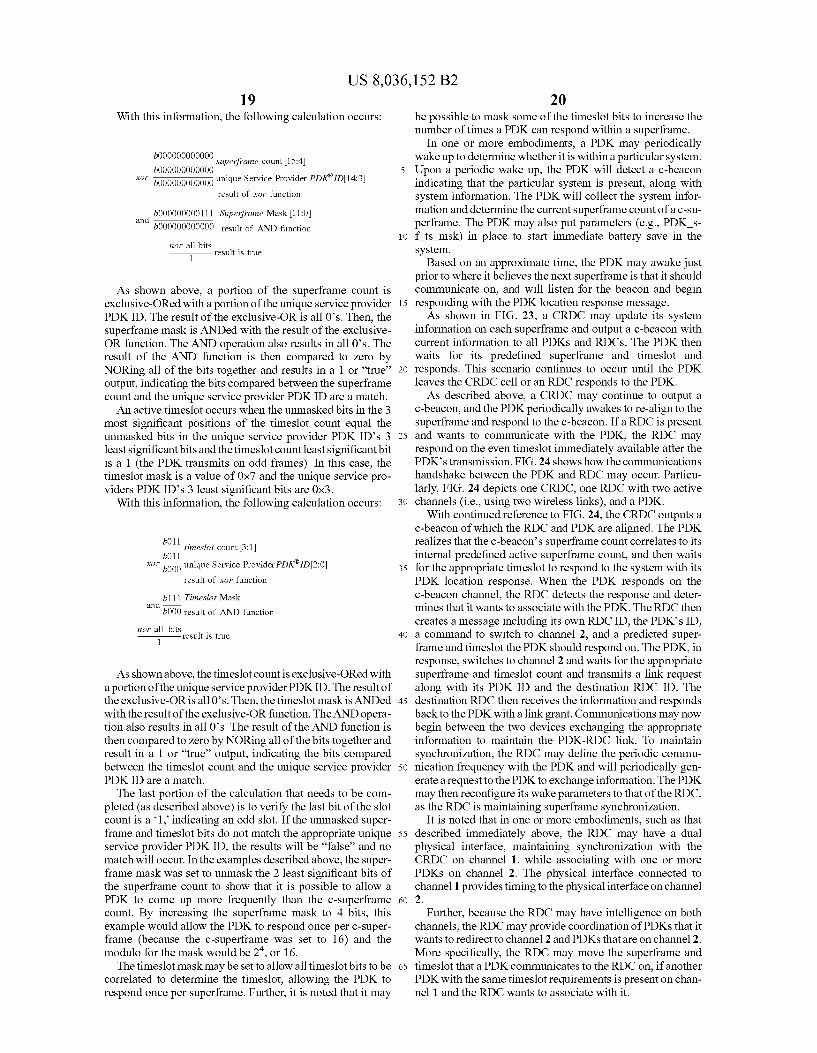
US 8,036,152 B2 19
With this information, the following calculation occurs:
bOOOOOOOOOOOO Superframe count 15:4) b000000000000 5
O 000000000000 unique Service Provider PDKID14:3) result of xor function
bOOOOOOOOO 111 Superframe Mask 11:0 3C
b000000000000 result of AND function 10
nor all bits 1 result is true
As shown above, a portion of the Superframe count is exclusive-ORed with a portion of the unique service provider 15 PDKID. The result of the exclusive-OR is all 0's. Then, the superframe mask is ANDed with the result of the exclusive OR function. The AND operation also results in all O's. The result of the AND function is then compared to Zero by NORing all of the bits together and results in a 1 or “true’ 20 output, indicating the bits compared between the Superframe count and the unique service provider PDKID are a match. An active timeslot occurs when the unmasked bits in the 3
most significant positions of the timeslot count equal the unmasked bits in the unique service provider PDK ID's 3 25 least significant bits and the timeslot count least significant bit is a 1 (the PDK transmits on odd frames). In this case, the timeslot mask is a value of 0x7 and the unique service pro viders PDKID's 3 least significant bits are 0x3.
With this information, the following calculation occurs: 30
b011 timeslot count 3:1 b011
wor O00 unique Service Provider PDKID2:0 35 result of xor function
d b111 Timeslot Mask "b000 result of AND function
nor all bits 1 result is true 40
As shown above, the timeslot count is exclusive-ORed with a portion of the unique service provider PDKID. The result of the exclusive-OR is all 0's. Then, the timeslot mask is ANDed 45 with the result of the exclusive-OR function. The AND opera tion also results in all 0's. The result of the AND function is then compared to Zero by NORing all of the bits together and result in a 1 or “true' output, indicating the bits compared between the timeslot count and the unique service provider 50 PDKID are a match. The last portion of the calculation that needs to be com
pleted (as described above) is to verify the last bit of the slot count is a 1 indicating an odd slot. If the unmasked Super frame and timeslot bits do not match the appropriate unique 55 service provider PDKID, the results will be “false' and no match will occur. In the examples described above, the super frame mask was set to unmask the 2 least significant bits of the Superframe count to show that it is possible to allow a PDK to come up more frequently than the c-superframe 60 count. By increasing the Superframe mask to 4 bits, this example would allow the PDK to respond once per c-super frame (because the c-superframe was set to 16) and the modulo for the mask would be 2, or 16. The timeslot mask may be set to allow all timeslot bits to be 65
correlated to determine the timeslot, allowing the PDK to respond once per Superframe. Further, it is noted that it may
20 be possible to mask some of the timeslot bits to increase the number of times a PDK can respond within a superframe.
In one or more embodiments, a PDK may periodically wake up to determine whether it is within a particular system. Upon a periodic wake up, the PDK will detect a c-beacon indicating that the particular system is present, along with system information. The PDK will collect the system infor mation and determine the current Superframe count of a c-Su perframe. The PDK may also put parameters (e.g., PDK s f tS msk) in place to start immediate battery save in the system.
Based on an approximate time, the PDK may awake just prior to where it believes the next superframe is that it should communicate on, and will listen for the beacon and begin responding with the PDK location response message. As shown in FIG. 23, a CRDC may update its system
information on each Superframe and output a c-beacon with current information to all PDKs and RDCs. The PDK then waits for its predefined superframe and timeslot and responds. This scenario continues to occur until the PDK leaves the CRDC cell or an RDC responds to the PDK. As described above, a CRDC may continue to output a
c-beacon, and the PDK periodically awakes to re-align to the superframe and respond to the c-beacon. If a RDC is present and wants to communicate with the PDK, the RDC may respond on the even timeslot immediately available after the PDK's transmission. FIG. 24 shows how the communications handshake between the PDK and RDC may occur. Particu larly, FIG. 24 depicts one CRDC, one RDC with two active channels (i.e., using two wireless links), and a PDK.
With continued reference to FIG. 24, the CRDC outputs a c-beacon of which the RDC and PDK are aligned. The PDK realizes that the c-beacon’s Superframe count correlates to its internal predefined active Superframe count, and then waits for the appropriate timeslot to respond to the system with its PDK location response. When the PDK responds on the c-beacon channel, the RDC detects the response and deter mines that it wants to associate with the PDK. The RDC then creates a message including its own RDC ID, the PDK's ID, a command to Switch to channel 2, and a predicted Super frame and timeslot the PDK should respondon. The PDK, in response, Switches to channel 2 and waits for the appropriate Superframe and timeslot count and transmits a link request along with its PDK ID and the destination RDC ID. The destination RDC then receives the information and responds back to the PDK with a link grant. Communications may now begin between the two devices exchanging the appropriate information to maintain the PDK-RDC link. To maintain synchronization, the RDC may define the periodic commu nication frequency with the PDK and will periodically gen erate a request to the PDK to exchange information. The PDK may then reconfigure its wake parameters to that of the RDC, as the RDC is maintaining Superframe synchronization.
It is noted that in one or more embodiments, such as that described immediately above, the RDC may have a dual physical interface, maintaining synchronization with the CRDC on channel 1, while associating with one or more PDKs on channel 2. The physical interface connected to channel 1 provides timing to the physical interface on channel 2.
Further, because the RDC may have intelligence on both channels, the RDC may provide coordination of PDKs that it wants to redirect to channel 2 and PDKs that are on channel 2. More specifically, the RDC may move the superframe and timeslot that a PDK communicates to the RDC on, if another PDK with the same timeslot requirements is present on chan nel 1 and the RDC wants to associate with it.

US 8,036,152 B2 21
CRDC Slot and Channel Coordination In one or more embodiments, a CRDC may be configured
via a remote connection to a server or automatically. Using remote configuration, the server may have knowledge of RDCs located within the CRDC cell boundary and may per form optimum channel and timeslot planning. When the CRDC is configured automatically, the CRDC
may scan all channels and find the channel with the least interference. The CRDC may then begin transmitting a c-bea CO.
All RDCs located within a CRDC cell boundary may place the CRDC into its local CRDC database and complete scan ning all other channels to determine if other CRDCs are present. In the case multiple CRDCs are found, the RDC may communicate to each CRDC its findings if possible.
Each CRDC may coordinate through that RDC to setup channels and timeslots to prevent interference between CRDCs. In one or more cases, the CRDC may select another channel and disregard the timeslot information because CRDCs may not be required to be timing coordinated. Fur ther, it is noted that any RDC that detects more than one CRDC may select the CRDC with the best signal quality. Protocol Operation The following describes a protocol operation in a single
cell coordinated system using a CRDC configuration. In one or more embodiments, there may be additional protocol fields required to allow interoperability between single cell and coordinated multi-cell configurations. Such additional proto col fields may provide information to RDCs and PDKs that are located in near proximity to each other, or within a CRDC cell. A network format field may provide information to RDCs
and PDKs related to the specific configuration the single cell or coordinated cells are operating in.
Name Valid Range Description Type
Proxense NWK FMT
Network Type Integer O to 7 O = Single Cell
CRDC 3 - 7 - RFU
Beacon Source O or 1 Binary O = RDC = CRDC
Broadcast Flag O or 1 Binary
= broadcast Timeslot Select Integer O to 3
O = no timeslots assigned
RDC uses odd timeslots
RDC uses even timeslots
5
10
15
25
30
= Multi-Cell coordinated 2 = Multi-Cell coordinated wif
Defines if this is a broadcast
= 802.15.4 Beacon enabled 2 = PDK (R) uses even timeslots
22 nated multi-cell with CRDC, the RDC may join the CRDC network if the site ID is the same.
The PDK may also receive this information and adjust its operating mode to comply with the system employed. If the PDK detects the system to be single cell, the PDK may conform to more of an IEEE 802.15.4 protocol, communicat ing with the RDC in such a manner. The PDK may be aware that it is required to communicate with a specific RDC ID. The PDK may still have the capability to periodically monitor other channels for other RDCs in the local vicinity.
If a PDK detects the system is multi-cell coordinated, the PDK may receive further information indicating the other RDC frequencies in use in the coordinated network and may adjust its system operating parameters appropriately.
If the PDK determines the system is multi-cell CRDC coordinated, the PDK may adjust its operating parameters appropriately. The PDK may acknowledge that a c-beacon is present and may broadcast a PDK location response. The PDK may also understand that an RDC with a different ID other than a CRDC ID may attempt to communication with the PDK.
A “beacon source' field may indicate to all RDCs and PDKs in the general proximity of the type of beacon being generated. This information may be helpful, specifically when in a multi-cell CRDC system, and allows RDCs to distinguish between RDC generated beacons and CRDC gen erated beacons.
A “broadcast flag’’ may indicate to all recipients that the information being sent is intentionally being broadcast to all devices that can receive particular protocol information. In Some cases, a message that may be sent to a specific PDK may
Defines the network configuration employed for an RDC or CRDC Defines the network type employed.
Defines the source of the beacon.
Defines how an RDC and PDK (R) utilize timeslots in a system.
3 = PDK (R) uses odd timeslots.
A network type value may be used to define a cell network also be broadcast to all PDKs. This flag assists the PDKs in configuration. An RDC receiving this field may determine its operating mode based on this field. If an RDC receives a network type of single cell from another transmitting RDC, the RDC may tune to another channel to avoid collisions with the other RDC. If the RDC receives a network type of coor dinated multi-cell, the RDC may join the multi-cell coordi nated system. If the RDC receives a network type of coordi
65
determining how to treat the information. A timeslot select field may indicate to PDKs and RDCs
how the timeslots are configured in the system. This field may further be used to determine if an RDC and PDK are to use even-based or odd-based timeslots for responding.
In order for an RDC or PDK to determine that a network is of a particular type, a network identifier may be used.
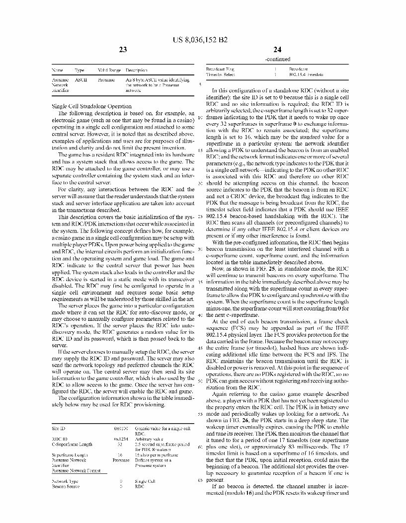
US 8,036,152 B2
Name Type Valid Range Description
Proxense ASCII Proxense An 8 byte ASCII value identifying Network the network to be a Proxense Identifier network
Single Cell Standalone Operation The following description is based on, for example, an
electronic game (such as one that may be found in a casino) operating in a single cell configuration and attached to some central server. However, it is noted that as described above, examples of applications and uses are for purposes of illus tration and clarity and do not limit the present invention.
The game has a resident RDC integrated into its hardware and has a system stack that allows access to the game. The RDC may be attached to the game controller, or may use a separate controller containing the system stack and an inter face to the central server.
For clarity, any interactions between the RDC and the server will assume that the reader understands that the system stack and server interface application are taken into account in the transactions described.
This description covers the basic initialization of the sys temand RDC/PDK interactions that occur while associated in the system. The following concept defines how, for example, a casino game in a single cell configuration may be setup with multiple player PDKs. Upon power being applied to the game and RDC, the internal circuits perform an initialization func tion and the operating system and game load. The game and RDC indicate to the central server that power has been applied. The system stack also loads in the controller and the RDC device is started in a static mode with its transceiver disabled. The RDC may first be configured to operate in a single cell environment and requires some basic setup requirements as will be understood by those skilled in the art. The server places the game into a particular configuration
mode where it can set the RDC for auto-discover mode, or may choose to manually configure parameters related to the RDC's operation. If the server places the RDC into auto discovery mode, the RDC generates a random value for its RDC ID and its password, which is then passed back to the SeVe.
If the server chooses to manually setup the RDC, the server may supply the RDC ID and password. The server may also send the network topology and preferred channels the RDC will operate on. The central server may then send its site information to the game controller, which is also used by the RDC to allow access to the game. Once the server has con figured the RDC, the server will enable the RDC and game. The configuration information shown in the table immedi
ately below may be used for RDC provisioning.
Site ID OXO100 Generic value for a single cell RDC.
RDC ID 0x1234 Arbitrary value C-Superframe Length 32 2.5 second Superframe period
for PDK (R) wakeup Superframe Length 16 16 slots per superframe Proxense Network Proxense Defines system as a Identifier Proxense system Proxense Network Format
Network Type O Single Cell Beacon Source O RDC
10
15
25
30
35
40
45
50
55
60
65
-continued
Broadcast Flag 1 Broadcast Timeslot Select 1 802.15.4 timeslots
In this configuration of a standalone RDC (without a site identifier): the site ID is set to 0 because this is a single cell RDC and no site information is required; the RDC ID is arbitrarily selected; the c-superframe length is set to 32 super frames indicating to the PDK that it needs to wake up once every 32 Superframes in Superframe 0 to exchange informa tion with the RDC to remain associated; the superframe length is set to 16, which may be the standard value for a Superframe in a particular system; the network identifier allowing a PDK to understand the beacon is from an enabled RDC; and the network format indicates one or more of several parameters (e.g., the network type indicates to the PDK that it is a single cell network indicating to the PDK no other RDC is associated with this RDC and therefore no other RDC should be attempting access on this channel, the beacon source indicates to the PDK that the beacon is from an RDC and not a CRDC device, the broadcast flag indicates to the PDK that the message is being broadcast from the RDC, the timeslot select field indicates that a PDK should use IEEE 802.15.4 beacon-based handshaking with the RDC). The RDC then scans all channels (or preconfigured channels) to determine if any other IEEE 802.15.4 or client devices are present or if any other interference is found.
With the pre-configured information, the RDC then begins beacon transmission on the least interfered channel with a c-Superframe count, Superframe count, and the information located in the table immediately described above. Now, as shown in FIG. 25, in standalone mode, the RDC
will continue to transmit beacons on every Superframe. The information in the table immediately described above may be transmitted along with the Superframe count in every Super frame to allow the PDK to configure and synchronize with the system. When the Superframe count is the Superframe length minus one, the Superframe count will start counting from 0 for the next c-superframe. At the end of each beacon transmission, a frame check
sequence (FCS) may be appended as part of the IEEE 802.15.4 physical layer. The FCS provides protection for the data carried in the frame. Because the beacon may not occupy the entire frame (or timeslot), hashed lines are shown indi cating additional idle time between the FCS and IFS. The RDC maintains the beacon transmission until the RDC is disabled or power is removed. At this point in the sequence of operations, there are no PDKs registered with the RDC, so no PDK can gain access without registering and receiving autho rization from the RDC.
Again referring to the casino game example described above, a player with a PDK that has not yet been registered to the property enters the RDC cell. The PDK is in battery save mode and periodically wakes up looking for a network. As shown in FIG. 26, the PDK starts in a deep sleep state. The wakeup timer eventually expires, causing the PDK to enable and tune its receiver. The PDK then monitors the channel that it tuned to for a period of one 17 timeslots (one superframe plus one slot), or approximately 83 milliseconds. The 17 timeslot limit is based on a superframe of 16 timeslots, and the fact that the PDK, upon initial reception, could miss the beginning of a beacon. The additional slot provides the over lap necessary to guarantee reception of a beacon if one is present.
If no beacon is detected, the channel number is incre mented (modulo 16) and the PDK resets its wakeup timer and

US 8,036,152 B2 25
returns to deep sleep mode. If a beacon is detected, the PDK checks for a network ID and if one is not found, it again increments the channel number, resets its wakeup timer, and returns to deep sleep mode. If the network ID is detected, the PDK attempts to establish a communications link with the RDC. At this point, the PDK has found a single cell network on channel 1 with an RDC ID of 0x1234, and the RDC is in broadcast mode indicating that it is attempting to gain the attention of any PDKs in the local proximity. Now referring to FIG. 27, in which an authorization denial
handshake is shown, the RDC broadcasts its beacon with the information as described above. The PDK detects the beacon in broadcast mode, determines the network configuration and RDC ID and returns a PDK location response with the RDC ID and PDKID included. The RDC detects the response from the PDKandalerts the central server that a PDK with a public ID of 0x9876 (arbitrary) wants to attach and enable the game for play. In the meantime, the RDC may immediately respond back to the PDK indicating that the PDK should wait for authorization. This keeps the PDK responding to beacons as defined by the fields located in the beacon until the beacon is no longer present (i.e., the PDK is no longer in the RDC cell), or until a response is returned by the RDC. The central sever, in conjunction with the system stack,
may then choose to not recognize a particular PDK's public ID that has not yet been registered to the property. The RDC continues to output its beacon. Upon the next wakeup and PDK location response from the PDK, the RDC detects the PDKID and, within its database, looks up the authorization parameters for this PDK. It determines that authorization has been denied and sends an "authorization deny’ command to the PDK. In the case that a particular PDK is not recognized or not authorized, a notification may sent to a staff member of the property to register a user of the PDK, and/or, in one or more embodiments, one or more machines may be used to prompt the user to register with the property.
The PDK temporarily stores the RDC ID in its local memory with a flag indicating that it shall no longer respond to this RDC ID. The PDK may then go back into battery save mode and periodically scans all channels as previously described above with reference to FIG. 26.
Still referring to FIG. 27, because the PDK may not con stantly be aware of its geographical location, the PDK may continue to monitor each channel and decode each beacon. Eventually, the PDK returns to the channel that the RDC is still transmitting beaconson, decodes the beacon information including the RDC ID, and determines that it is not to respond.
Further, the PDK may maintain the RDC ID in its local database until the beacon is no longer present during scan ning, at which time the RDC ID is removed from the database. The period of time that the beacon is absent before removing the RDC ID from the database may be determined during prior system testing.
Assuming the RDC beacon is absent for a given period of time indicates to the PDK that the PDK has left the RDC cell. Upon the next detection of that RDC beacon, the PDK may again attempt to gain access to the RDC as shown in FIG. 27. The difference this time is the PDKID is in the RDC's local database and the RDC may deny authorization without alert ing the host system. The PDK may then operate as previously described after authorization has been denied.
In one or more embodiments, once a host system grants authorization for the PDK to operate within the property, then one or more different scenarios may exist. In one scenario, the RDC may transmit the PDKID as part of the beacon trans mission, alerting the PDK that the RDC wants to communi
10
15
25
30
35
40
45
50
55
60
65
26 cate, and the PDK may then respond with a PDK location response. In another scenario, the PDK returns to the RDC cell, and after detection of the beacon (with or without the PDKID), it returns the PDK location response. In either case, after the RDC detects the PDK location response with the PDK's public ID, the RDC then issues a link request attempt ing to initiate a link between the RDC and PDK. FIG. 28, for example, shows a handshake between the RDC and PDK for a PDK authorization grant. As shown in FIG. 28, the RDC may broadcast the beacon
on every Superframe. Although not shown, the Superframe counter value is also included, which the PDK may use for battery conservation. The beacon may be broadcast in one of more different methods. The system may have just authorized a PDK and the beacon includes the PDK's public ID for a period of time or, in another method, the beacon may be transmitted without the PDKs public ID. As described above, if the PDK is in the RDC cell and has deactivated its response, when the PDK detects its ID in the beacon, it may reactivate its response to the RDC and transmit both the RDC ID and PDK public ID in its PDK location response.
If the PDK has just re-entered the RDC cell and detects the RDC beacon (with or without the PDK's public ID), the PDK may again respond with the RDC ID and its own PDK public ID. The RDC may then detect its RDC ID and the PDK public ID and immediately sends a link request to the PDK with both its RDC ID and the PDKs public ID indicating it wants to initiate a link with the PDK. The PDK may detect the request and respond with a link grant with both IDs included. The RDC and PDK may enter into association mode and then provide data exchange on a periodic basis insuring the PDK remains in range of the RDC. This periodic data exchange may occur based on parameters previously described above. Interleaved between the data exchange may be beacons that other PDKs may use to access the RDC. Eventually, the RDC may terminate the data exchange based on inactivity, as deter mined by the server, or as based on the PDK leaving the RDC cell, in which case the RDC realizes the PDK is no longer in range.
Further, it is noted that due to radio interference issues that might occur in wireless systems, the RDC and PDK may not relinquish the link based on the lack of a single data exchange. Because the RDC is not necessarily battery limited, the RDC may continue to monitor all timeslots in a Superframe with the exception of those frames it transmits on. In contrast, it is noted that a PDK is likely battery limited and therefore may need to intelligently choose when to receive and transmit.
In the case the RDC and PDKlose communications during the predefined period they are attempting to communicate, both devices may have equal knowledge of Such an event. Because the PDK is battery limited, the PDK may try on the next available timeslot to regain synchronization with the RDC. After a period of time in the RDC, or a predefined number of attempts by the PDK, the link may be considered lost.
Referring again to the casino game example, in one or more embodiments, an enabled single cell game facilitates multi player access via the central server. Individual players may consecutively play the game provided they have the appro priate PDK, or in Some instances, multiple players may be able to simultaneously play the game. The RDC allows for simultaneous multi-player access, so long as the central server Supports and authorizes Such play.
In the case where multiple PDKs may simultaneously access an RDC, the RDC may provide superframe coordina tion information to the PDKs to interleave them in a manner to avoid contention between RDC and PDK communications.
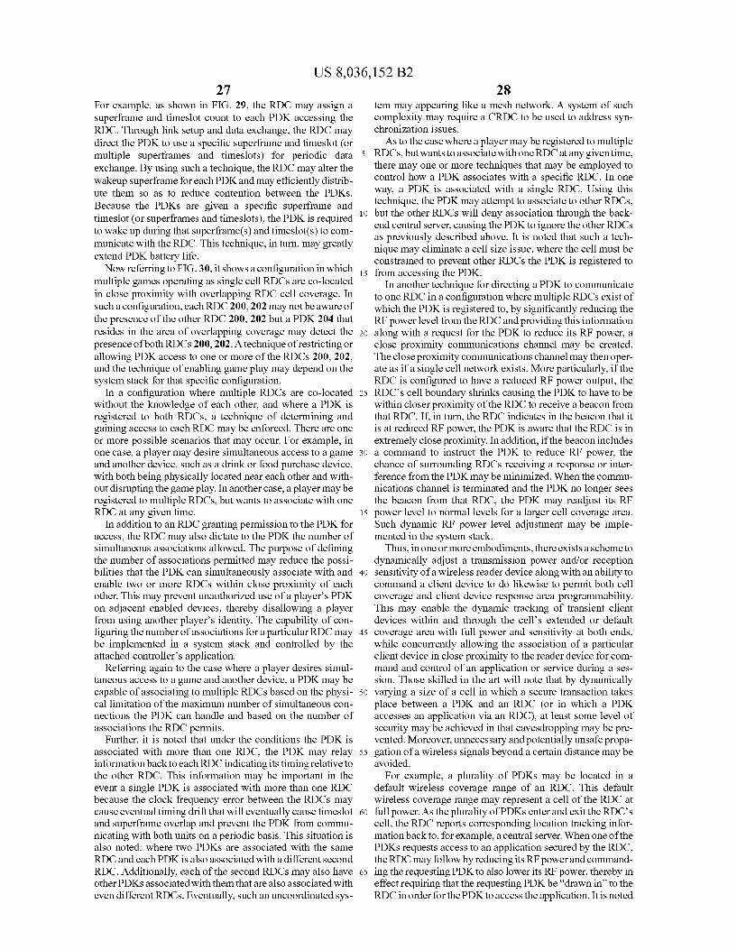
US 8,036,152 B2 27
For example, as shown in FIG. 29, the RDC may assign a Superframe and timeslot count to each PDK accessing the RDC. Through link setup and data exchange, the RDC may direct the PDK to use a specific superframe and timeslot (or multiple Superframes and timeslots) for periodic data exchange. By using Such a technique, the RDC may alter the wakeup superframe for each PDK and may efficiently distrib ute them so as to reduce contention between the PDKs. Because the PDKs are given a specific superframe and timeslot (or superframes and timeslots), the PDK is required to wake up during that Superframe(s) and timeslot(s) to com municate with the RDC. This technique, in turn, may greatly extend PDK battery life. Now referring to FIG.30, it shows a configuration in which
multiple games operating as single cell RDCs are co-located in close proximity with overlapping RDC cell coverage. In such a configuration, each RDC 200,202 may not be aware of the presence of the other RDC 200, 202 but a PDK204 that resides in the area of overlapping coverage may detect the presence of both RDCs 200, 202. A technique of restricting or allowing PDK access to one or more of the RDCs 200, 202, and the technique of enabling game play may depend on the system stack for that specific configuration.
In a configuration where multiple RDCs are co-located without the knowledge of each other, and where a PDK is registered to both RDCs, a technique of determining and gaining access to each RDC may be enforced. There are one or more possible scenarios that may occur. For example, in one case, a player may desire simultaneous access to a game and another device. Such as a drink or food purchase device, with both being physically located near each other and with out disrupting the game play. In another case, a player may be registered to multiple RDCs, but wants to associate with one RDC at any given time.
In addition to an RDC granting permission to the PDK for access, the RDC may also dictate to the PDK the number of simultaneous associations allowed. The purpose of defining the number of associations permitted may reduce the possi bilities that the PDK can simultaneously associate with and enable two or more RDCs within close proximity of each other. This may prevent unauthorized use of a player's PDK on adjacent enabled devices, thereby disallowing a player from using another player's identity. The capability of con figuring the number of associations for a particular RDC may be implemented in a system stack and controlled by the attached controller's application.
Referring again to the case where a player desires simul taneous access to a game and another device, a PDK may be capable of associating to multiple RDCs based on the physi cal limitation of the maximum number of simultaneous con nections the PDK can handle and based on the number of associations the RDC permits.
Further, it is noted that under the conditions the PDK is associated with more than one RDC, the PDK may relay information back to each RDC indicating its timing relative to the other RDC. This information may be important in the event a single PDK is associated with more than one RDC because the clock frequency error between the RDCs may cause eventual timing drift that will eventually cause timeslot and superframe overlap and prevent the PDK from commu nicating with both units on a periodic basis. This situation is also noted: where two PDKs are associated with the same RDC and each PDK is also associated with a different second RDC. Additionally, each of the second RDCs may also have other PDKs associated with them that are also associated with even different RDCs. Eventually, such an uncoordinated sys
10
15
25
30
35
40
45
50
55
60
65
28 tem may appearing like a mesh network. A system of Such complexity may require a CRDC to be used to address syn chronization issues. As to the case where a player may be registered to multiple
RDCs, but wants to associate with one RDC at any given time, there may one or more techniques that may be employed to control how a PDK associates with a specific RDC. In one way, a PDK is associated with a single RDC. Using this technique, the PDK may attempt to associate to other RDCs, but the other RDCs will deny association through the back end central server, causing the PDK to ignore the other RDCs as previously described above. It is noted that such a tech nique may eliminate a cell size issue, where the cell must be constrained to prevent other RDCs the PDK is registered to from accessing the PDK.
In another technique for directing a PDK to communicate to one RDC in a configuration where multiple RDCs exist of which the PDK is registered to, by significantly reducing the RF power level from the RDC and providing this information along with a request for the PDK to reduce its RF power, a close proximity communications channel may be created. The close proximity communications channel may then oper ate as if a single cell network exists. More particularly, if the RDC is configured to have a reduced RF power output, the RDC's cell boundary shrinks causing the PDK to have to be within closer proximity of the RDC to receive a beacon from that RDC. If, in turn, the RDC indicates in the beacon that it is at reduced RF power, the PDK is aware that the RDC is in extremely close proximity. In addition, if the beacon includes a command to instruct the PDK to reduce RF power, the chance of Surrounding RDCs receiving a response or inter ference from the PDK may be minimized. When the commu nications channel is terminated and the PDK no longer sees the beacon from that RDC, the PDK may readjust its RF power level to normal levels for a larger cell coverage area. Such dynamic RF power level adjustment may be imple mented in the system stack.
Thus, in one or more embodiments, there exists a scheme to dynamically adjust a transmission power and/or reception sensitivity of a wireless reader device along with an ability to command a client device to do likewise to permit both cell coverage and client device response area programmability. This may enable the dynamic tracking of transient client devices within and through the cells extended or default coverage area with full power and sensitivity at both ends, while concurrently allowing the association of a particular client device in close proximity to the reader device for com mand and control of an application or service during a ses sion. Those skilled in the art will note that by dynamically varying a size of a cell in which a secure transaction takes place between a PDK and an RDC (or in which a PDK accesses an application via an RDC), at least some level of security may be achieved in that eavesdropping may be pre vented. Moreover, unnecessary and potentially unsafe propa gation of a wireless signals beyond a certain distance may be avoided.
For example, a plurality of PDKs may be located in a default wireless coverage range of an RDC. This default wireless coverage range may represent a cell of the RDC at full power. As the plurality of PDKs enter and exit the RDC's cell, the RDC reports corresponding location tracking infor mation back to, for example, a central server. When one of the PDKs requests access to an application secured by the RDC, the RDC may follow by reducing its RF power and command ing the requesting PDK to also lower its RF power, thereby in effect requiring that the requesting PDK be “drawn in to the RDC in order for the PDK to access the application. It is noted

US 8,036,152 B2 29
that while the RDC may communicate with the requesting PDK via low power RF signals, the RDC may continue to maintain its default wireless coverage range for tracking other PDKs. When the requesting PDK is moved away from the RDC or the session is otherwise terminated, both ends return 5 to their default full RF power settings. As described above, reception sensitivity of the RDC and/
or PDK may be changed as part of a cell size variation tech nique in accordance with one or more embodiments. Recep tion sensitivity may be adjusted using an RF attenuator (e.g., a step, variable, or programmable RF attenuator) that is either specific to a receive path or common to both receive and transmit paths. It is noted that even if the attenuator is com mon to both receive and transmit paths, transmit power may be independently controlled. Further, in one or more embodi ments, a separate attenuator may be used to allow for inde pendent control of transmission power and reception sensi tivity.
To determine how much to adjust the size of a wireless cell 20 without severing a wireless connection between an RDC and a PDK, one or more of various metrics may be used. For example, in one or more embodiments, a signal strength of the PDK may be monitored to determine by how much to power down a transmission power of the RDC and/or the PDK. If the 25 signal strength is determined to be relatively strong, then the RDC may cause a reduction in transmission power that is greater than if the signal strength were detected as being weak. Conversely, if the signal strength is detected as being weak, the RDC may lower transmission power by a small amount or not at all. Instead of or in addition to relying on signal strength, a bit error rate may be assessed to determine by how much to power down the transmission power. For example, if the bit error rate of communications between the RDC and PDK is determined to be low, then the RDC may lower transmission power by an amount greater than if the bit error rate was determined to be relatively high.
Further, as described above, the transmission power and/or reception sensitivity of either or both of an RDC and a PDK 40 may be adjusted. In one or more embodiments, only a trans mission power of the PDK may be adjusted. This may done to, for example, “bring in the PDK and reduce the likelihood of that PDK interfering with other RDCs. In one or more other embodiments, the transmission power of both the RDC and 45 the PDK may be adjusted in an effort to draw in the PDK to the RDC. Instill one or more other embodiments, in addition to or instead of adjusting transmission power, reception sensitivity of either or both of the RDC and the PDK may be changed.
Moreover, in one or more embodiments, an RDC may have 50 multiple wireless transceivers, whereby at least one of the transceivers is at full power for PDK location tracking pur poses, while one or more of the other transceivers are used to establish adjustable wireless cells for particular associations with PDKs. For example, in the case of an ATM machine 55 having an RDC, the RDC may carry out a secure transaction with a PDK in an adjusted wireless cell, while at the same time, casting a broader wireless cell to monitor and identify one or more PDKs around the transacting PDK. In such a manner, for example, a security measure may be imple- 60 mented by which the RDC can identify individuals behind a transacting user. Further, as an added or alternative security measure, transmission power may be adjusted dependent on a sensitivity of the type of data requested to be exchanged in a particular transaction. Such data sensitive transactions may 65 be conducted at low power with additional security measures Such as password entry or biometric input.
10
15
30
35
30 Application Utilizing Multi-Cell Coordination The following describes a system architecture and opera
tion of a system within, for example, a casino application. Referring to FIG. 31, a CRDC (not shown) and multiple RDCs (shown, but not individually labeled) are distributed throughout a casino floor. In Such embodiments, a single CRDC generates a cell 210 that provides ubiquitous coverage of the entire floor. On the left side of FIG. 31, multiple RDCs (shown, but not labeled) provide overlapping cell coverage and blanket the casino floor and gaming table area 212 all the way to an entrance of the casino with continuous wireless service coverage. These RDCs may be dedicated to PDK location tracking, allowing the casino operator to know where a player carrying his/her PDK is geographically located on the floor. These RDCs may be mounted in the floor or ceiling, creating, for example, relatively symmetrical cells.
Another set of RDC cells (shown, but not labeled) are shown to exist in the right side of FIG. 31 and are integrated in gaming machines (shown, but not labeled) within an elec tronic gaming area 214. The cell orientation for these RDCs is more oblong and focused at players that are within close proximity and in front of the electronic gaming machines, noting that cell orientation and shape may be set according to antenna position and/or configuration. The cells extend out ward towards the center of the isle to detect the presence of a player that may be walking by. Toward the lower right part of FIG.31 is a registration cell 216 that sits at a registration desk (shown, but not labeled) where a player may register and acquire a PDK the first time the player enters the casino. The registration cell 216 may be smaller in size to enable local communications between the RDC and PDK without allow ing external RF monitoring devices to capture and record the interaction between the devices.
It is noted that in FIG. 31, a PDK218 that is currently out of the range of all RDCs, but still in range of the CRDC. This represents a PDK carried by a player, which is being used to track the player's position and provide additional services. Such services are further described below.
Further, still referring to FIG. 31, there is a central server 220. The central server 220 may contain a player's financial information (credit card numbers, gambling limits, and other information related to a player). In addition, the central server 220 may be physically wired (not shown) to all RDCs and/or CRDCs located throughout the casino.
Although not shown in FIG. 31, within the PDK location tracking system, RDCs may be gambling tables that also have RDCs embedded within the table itself A representative gam bling table is shown in FIG. 32. As shown in FIG. 32, a gambling table 230 has RDCs 232,
234, 236, 238,240, 242, 244, 246 embedded within it. RDC 246 may be a dealer RDC that has a cell geometry covering the dealers area, allowing the dealerto freely move around in this area. There are an additional RDCs 232, 234, 236, 238, 240,242, 244 that are located at each player position. Each of these RDC cells coverage areas are oblong and are directed to where the player would be sitting/standing. It is noted that each player position's RDC232,234,236,238,240,242,244 allows for some coverage of the region directly behind each player position, allowing the RDC 232, 234, 236, 238, 240, 242, 244 to report back through the system the presence and identity of anyone behind the player. The RDC cell's cover age areas may be minimized to cover the area where a dealer or player may be located relative to the table. Those skilled in the art will note that the actual cell footprints may vary from those shown in FIG. 32. Utilizing distributed RDCs with directional, highly attenuated, antennas allows the casino
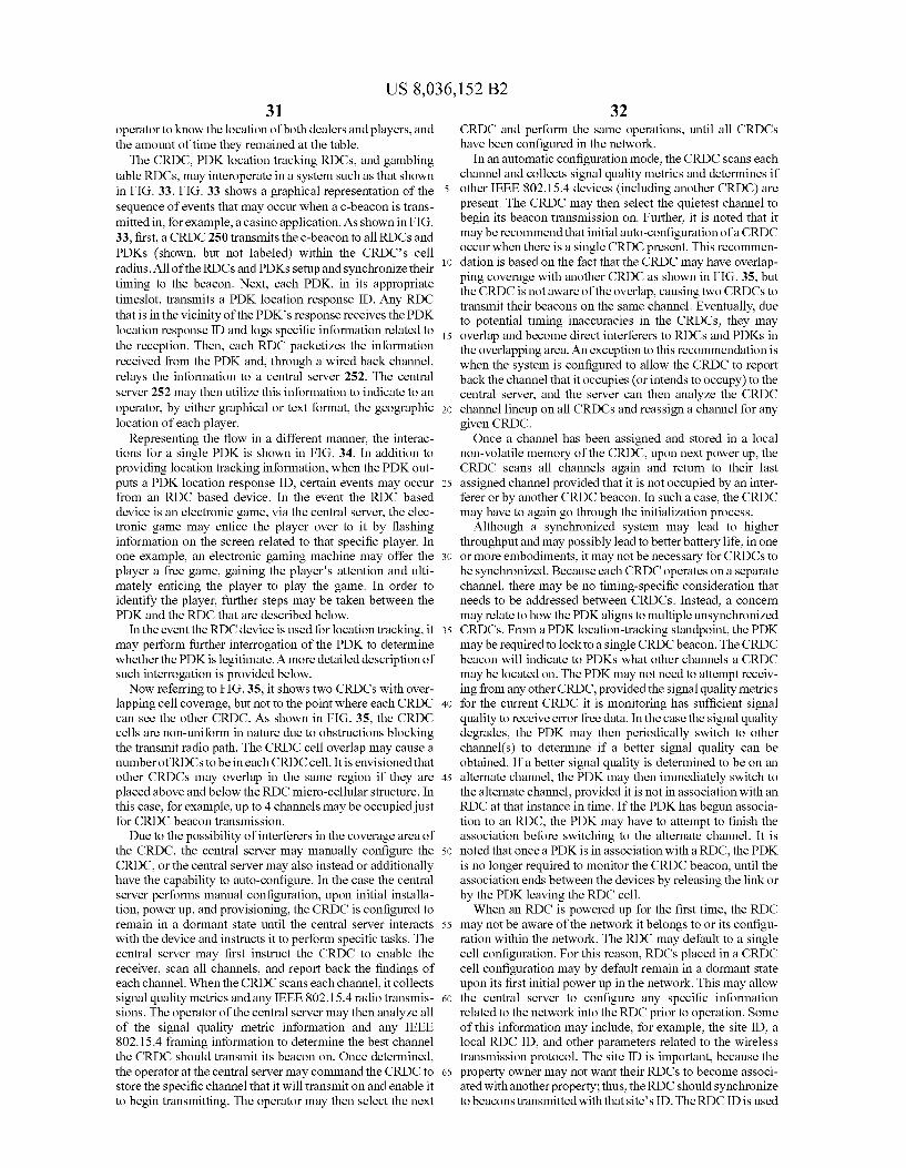
US 8,036,152 B2 31
operator to know the location of both dealers and players, and the amount of time they remained at the table.
The CRDC, PDK location tracking RDCs, and gambling table RDCs, may interoperate in a system Such as that shown in FIG. 33. FIG. 33 shows a graphical representation of the sequence of events that may occur when a c-beacon is trans mitted in, for example, a casino application. As shown in FIG. 33, first, a CRDC 250 transmits the c-beacon to all RDCs and PDKs (shown, but not labeled) within the CRDC's cell radius. All of the RDCs and PDKs setup and synchronize their timing to the beacon. Next, each PDK, in its appropriate timeslot, transmits a PDK location response ID. Any RDC that is in the vicinity of the PDK's response receives the PDK location response ID and logs specific information related to the reception. Then, each RDC packetizes the information received from the PDK and, through a wired back channel, relays the information to a central server 252. The central server 252 may then utilize this information to indicate to an operator, by either graphical or text format, the geographic location of each player.
Representing the flow in a different manner, the interac tions for a single PDK is shown in FIG. 34. In addition to providing location tracking information, when the PDK out puts a PDK location response ID, certain events may occur from an RDC based device. In the event the RDC based device is an electronic game, via the central server, the elec tronic game may entice the player over to it by flashing information on the screen related to that specific player. In one example, an electronic gaming machine may offer the player a free game, gaining the player's attention and ulti mately enticing the player to play the game. In order to identify the player, further steps may be taken between the PDK and the RDC that are described below.
In the event the RDC device is used for location tracking, it may perform further interrogation of the PDK to determine whether the PDK is legitimate. A more detailed description of Such interrogation is provided below. Now referring to FIG.35, it shows two CRDCs with over
lapping cell coverage, but not to the point where each CRDC can see the other CRDC. As shown in FIG. 35, the CRDC cells are non-uniform in nature due to obstructions blocking the transmit radio path. The CRDC cell overlap may cause a number of RDCs to be in each CRDC cell. It is envisioned that other CRDCs may overlap in the same region if they are placed above and below the RDC micro-cellular structure. In this case, for example, up to 4 channels may be occupied just for CRDC beacon transmission. Due to the possibility of interferers in the coverage area of
the CRDC, the central server may manually configure the CRDC, or the central server may also instead or additionally have the capability to auto-configure. In the case the central server performs manual configuration, upon initial installa tion, power up, and provisioning, the CRDC is configured to remain in a dormant state until the central server interacts with the device and instructs it to perform specific tasks. The central server may first instruct the CRDC to enable the receiver, Scan all channels, and report back the findings of each channel. When the CRDC scans each channel, it collects signal quality metrics and any IEEE 802.15.4 radio transmis sions. The operator of the central server may then analyze all of the signal quality metric information and any IEEE 802.15.4 framing information to determine the best channel the CRDC should transmit its beacon on. Once determined, the operator at the central server may command the CRDC to store the specific channel that it will transmit on and enable it to begin transmitting. The operator may then select the next
5
10
15
25
30
35
40
45
50
55
60
65
32 CRDC and perform the same operations, until all CRDCs have been configured in the network.
In an automatic configuration mode, the CRDC scans each channel and collects signal quality metrics and determines if other IEEE 802.15.4 devices (including another CRDC) are present. The CRDC may then select the quietest channel to begin its beacon transmission on. Further, it is noted that it may be recommend that initial auto-configuration of a CRDC occur when there is a single CRDC present. This recommen dation is based on the fact that the CRDC may have overlap ping coverage with another CRDC as shown in FIG. 35, but the CRDC is not aware of the overlap, causing two CRDCs to transmit their beacons on the same channel. Eventually, due to potential timing inaccuracies in the CRDCs, they may overlap and become direct interferers to RDCs and PDKs in the overlapping area. An exception to this recommendation is when the system is configured to allow the CRDC to report back the channel that it occupies (or intends to occupy) to the central server, and the server can then analyze the CRDC channel lineup on all CRDCs and reassign a channel for any given CRDC. Once a channel has been assigned and stored in a local
non-volatile memory of the CRDC, upon next power up, the CRDC scans all channels again and return to their last assigned channel provided that it is not occupied by an inter ferer or by another CRDC beacon. In such a case, the CRDC may have to again go through the initialization process.
Although a synchronized system may lead to higher throughput and may possibly lead to better battery life, in one or more embodiments, it may not be necessary for CRDCs to be synchronized. Because each CRDC operates on a separate channel, there may be no timing-specific consideration that needs to be addressed between CRDCs. Instead, a concern may relate to how the PDKaligns to multiple unsynchronized CRDCs. From a PDK location-tracking standpoint, the PDK may be required to lock to a single CRDC beacon. The CRDC beacon will indicate to PDKs what other channels a CRDC may be located on. The PDK may not need to attempt receiv ing from any other CRDC, provided the signal quality metrics for the current CRDC it is monitoring has sufficient signal quality to receive error free data. In the case the signal quality degrades, the PDK may then periodically switch to other channel(s) to determine if a better signal quality can be obtained. If a better signal quality is determined to be on an alternate channel, the PDK may then immediately switch to the alternate channel, provided it is not in association with an RDC at that instance in time. If the PDK has begun associa tion to an RDC, the PDK may have to attempt to finish the association before Switching to the alternate channel. It is noted that once a PDK is in association with a RDC, the PDK is no longer required to monitor the CRDC beacon, until the association ends between the devices by releasing the link or by the PDK leaving the RDC cell. When an RDC is powered up for the first time, the RDC
may not be aware of the network it belongs to or its configu ration within the network. The RDC may default to a single cell configuration. For this reason, RDCs placed in a CRDC cell configuration may by default remain in a dormant state upon its first initial power up in the network. This may allow the central server to configure any specific information related to the network into the RDC prior to operation. Some of this information may include, for example, the site ID, a local RDC ID, and other parameters related to the wireless transmission protocol. The site ID is important, because the property owner may not want their RDCs to become associ ated with another property; thus, the RDC should synchronize to beaconstransmitted with that site's ID. The RDC ID is used

US 8,036,152 B2 33
in communication between a PDK and RDC; hence, there should be one RDC ID per RDC device in the network. Other application-dependent parameters may include how the unit operates when associated with a PDK and whether the RDC sends data back to the server when data is ready, or if the server must poll the RDC for the information. The central server may then command the RDC to enable its receiver and scan all channels to determine the signal quality of each channel and which CRDCs may be received by the RDC. The operator of the central server may allow the RDC to automati cally select which CRDC Beacon to lock to, or can command the RDC to select a specific CRDC beacon. After reviewing the channel list for signal quality, the system may then com mand which channels the RDC can use for alternate channels for RDC-PDK communications, or the system may command the RDC to automatically select the alternate channels. The system may then place the RDC in operation mode, and the RDC then tunes to the selected CRDC beacon channel and remains there listening for CRDC beacons and any PDK that sends a PDK location response ID. While receiving the c-bea con, the RDC may configure its timeslot information similar to that described above. This defines the superframe structure as well as defining which timeslots (odd or even) the RDC is permitted to communicate with a PDK on the beacon channel.
In the background, on the alternate wireless link described above with reference to FIG.9, the RDC may continue to scan the alternate channels, updating its list of clear channels. This updated list may then be used when a RDC determines it wants to extend its communication with a PDK in association mode and selects which channel that communication will occur on. The RDC, in operational mode, may perform frame and slot alignment to the CRDC and listen for a PDK location tracking response. On a periodic basis, the RDC may send information back to the central server indicating that it is still operational and indicating the status of the communications channels (e.g., CRDC beacon, alternate channels).
In one or more embodiments, a registration RDC may be used to initially enable and to configure a PDK. The registra tion RDC may have a small cell coverage area by design, measured, for example, in inches. This may require that the unregistered PDK must be in extremely close proximity, e.g., placed on the registration RDC housing, to communicate with the registration RDC, reducing the likelihood of RF eaves droppers gaining access to PDK setup information. The registration RDC may be directly connected to a cen
tral server. In addition to specific security features, the regis tration RDC installs and configures service provider informa tion located on the central server (described above with reference to FIGS. 6 and 7). Such information may include the service provider ID, secret key, and other parameters that the service provider wants to designate for access within their network. These other parameters may vary in size in the PDK and may be defined by the host system to meet the needs of the property. Information transferred to a PDK may include, for example, the service provider site ID, the service providers assigned PDKID, the service provider's secret service ID, the service provider's secret key, and service provider specific access information. Now describing an example of an operation in accordance
with one or more embodiments, once a system has been installed and properly provisioned, a rated player may walk into the casino. They are greeted by a host and walked over to the registration desk, where the players information, already in the central server, is linked to a PDK that is given to the player and assigned with specific privileges. The player places the PDK in their pocket and begins to walkthroughout the casino. Once the PDKleaves the registration cell, the PDK
10
15
25
30
35
40
45
50
55
60
65
34 enters discovery mode and scans the channels for a c-Beacon. If the PDK does not locate the c-beacon, it continues to scan for an undetermined period of time until it either goes into battery save mode or finds a c-beacon. Once the PDK finds ac-Beacon, the PDK determines if the
c-beacon is a particular type of network and the site ID is in its local service provider database. If the site ID is not in the database, the PDK ignores that c-beacon and keeps looking for other c-beacons on other channels until one is found that is in its local database. Once a valid c-beacon containing a site ID that is in the PDK's local database is found, the PDK extracts the CRDC channel availability flags and checks the other channels in the CRDC channel availability list. The PDK then determines which CRDC has the best signal quality metrics. The PDK switches to that channel and begins receiv ing c-beacons. The PDK extracts the CRDC and network configuration information as described above. This informa tion may define the framing structure and how the PDK should operate within the network. The PDK then applies the c-beacon parameters to its radio transceiver parameters, con figuring the sleep interval and response Superframe and timeslot information. Because the PDK has just received a c-beacon, the PDK is now aware of the current superframe count. The PDK then configures its timerto wake up just prior to the expected Superframe count that it may communicate O.
Now also referring to FIG. 36, when the sleep timer expires, the PDK may wake up, listen for a specific c-beacon, and verify the superframe count. It then waits a predeter mined period of time for its slot to be available and performs CSMA-CA, and if no other device is attempting to respond, it responds with its PDK location tracking response. If another device was detected on the channel, the PDK may then reset its timers and wait for the next predefined superframe and timeslot to wake up and attempt again.
It is noted that a PDK in accordance with one or more embodiments may be powered by an internal battery of, for example, a type commonly used to power Small electronic devices such as watches, calculators, and mobile computing devices. The power of such a client device battery is con sumed when the PDK is active. In an effort to reduce and/or minimize battery consumption, in one or more embodiments, the active time of a PDK as a percentage of total time may be reduced by management of transmission and reception times. For example, as described above, a network in accordance with one or more embodiments may be designed to configure time slots (e.g., frames), groups of time slots (e.g., Super frames), and/or coordinating beacon Superframes (e.g., c-Su perframes) in a manner Such that a client device is caused to both listen and respond within specific time slots. Because these time slots are configured by the network, they may be precisely predicted, thereby allowing the client device to set a timer, return to sleep mode, and waken when a specific, time-slotted interaction is expected or required of the client device. Further, in one or more embodiments, because a net work in accordance with one or more embodiments may implement programmable c-Superframe lengths, an operator or system may individually tailor performance to maximize (or at least improve) battery life and/or minimize (or at least reduce) system inter-message latency without requiring access of the client device itself or physical alteration of the client device. When the PDK responds with a PDK location tracking
response, every RDC within local proximity that can receive the response may log the response message in its database along with signal quality metrics and a timestamp. They will then send the information back to the central server. The
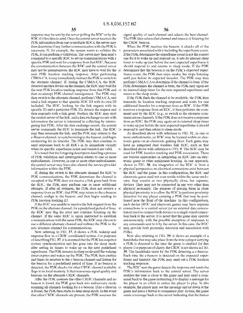
US 8,036,152 B2 35
response may be sent by the server polling the RDC or by the RDC if it has data to send. Once the central server receives the PDK information from one or multiple RDCs, the server may then determine if any further communication with the PDK is necessary. If, for example, the system wants to validate the PDK, it can perform a validation. The server may then send a command to a specific RDC to set up communications with a specific PDK and wait for a response from that RDC. Because the communication between the RDC and the central server may not be instantaneous, the RDC may have to wait for the next PDK location tracking response. After performing CSMA-CA, it may immediately instruct the PDK to switch to the alternate channel. If, during the CSMA-CA, the RDC detected another device on the channel, the RDC may wait for the next PDK location tracking response from that PDK and then re-attempt PDK channel reassignment. The PDK may then switch to the alternate channel, perform CSMA-CA, and send a link request to that specific RDC ID with its own ID included. The RDC, looking for the link request with its specific ID and a particular PDKID, detects the request and then responds with a link grant. Further, the RDC may alert the central server of the link, and a data exchange occurs with information the server is interested in collecting by interro gating that PDK. After the data exchange occurs, the central server commands the RDC to terminate the link. The RDC may then terminate the link, and the PDK may returns to the c-Beacon channel, re-synchronizing to the beacon, and begin monitoring for its timeslot. The PDK may then continue to send responses back to all RDCs in its immediate vicinity when its specific Superframe count and timeslot are valid.
It is noted that the foregoing description detailing a process of PDK validation and interrogation relates to one or more embodiments. However, in one or more other embodiments, the central server may have also altered the service provider information within the PDK.
If, during the switch to the alternate channel for RDC to PDK communications, the PDK determines the channel is occupied or the PDK does not receive a link grant back from the RDC, the PDK may perform one or more additional attempts. If after all attempts, the PDK does not receive a response from an RDC, that PDK may return to the c-beacon channel, realign to the beacon, and then begin sending its PDK location tracking ID.
If the RDC was unable to receive the link request from the PDK on the alternate channel, for a predefined period of time, the RDC may flag the error and continue listening on the channel. If the same RDC is again instructed to establish communications with the same PDK, the RDC may choose to use a different alternate channel and redirect the PDK to the new alternate channel for communications. Now referring to FIG. 37, it shows a PDK wakeup and
response flow in a CRDC coordinated system. For purposes of describing FIG.37, it is assumed that the PDK has acquired system synchronization and has gone into the sleep mode after setting its timers to wake up on the next predefined superframe. The PDK remains in sleep mode until the wakeup timer expires and wakes up the PDK. The PDK then enables and tunes its receiver to the c-beacon channel and listens for the beacon for a predefined period of time. If no beacon is detected, the PDK checks for other CRDC channel available flags in its local memory. It then reassesses signal quality and beacons on the alternate CRDC channels.
After the PDK assesses the other CRDC channels and no beacon is found, the PDK goes back into rediscovery mode scanning all channels looking for a c-beacon. If no c-Beacon is found, the PDK then starts its deep sleep mode. In the event that other CRDC channels are present, the PDKassesses the
10
15
25
30
35
40
45
50
55
60
65
36 signal quality of each channel and selects the best channel. The PDK then selects that channel and tunes to it listening for the CRDC beacon. When the PDK receives the beacon, it checks all of the
parameters associated with it including the Superframe count. If the PDK determines the Superframe count is not the correct one for it to wake up and respond on, it sets its internal sleep timer to wake up just before the next expected superframe it should respond to and returns to sleep mode. If the PDK determines that the beacon is on the PDK's expected super frame count, the PDK then stays awake, but stops listening until just before its expected timeslot. The PDK may then perform CSMA-CA to determine if the channel is busy. If the PDK determines the channel is busy, the PDK may again set its internal sleep timer for the next expected Superframe and return to the sleep mode.
If the PDK finds the channel to be available, the PDK then transmits its location tracking response and waits for one additional timeslot for a response from an RDC. If the PDK receives a response from an RDC, it then performs the com mand sent by the RDC (e.g., to switch to the alternate com munications channel). If the PDK does not receive a response from an RDC, the PDK may again set its internal sleep timer to wake up just before the next expected superframe it should respond to and then return to sleep mode. As described above with reference to FIG. 31, in one or
more embodiments, an RDC may be located within an elec tronic game on an electronic gaming floor. Each game may have an integrated dual wireless link RDC, such as that described above with reference to FIG. 9. The RDC may be used for PDK location tracking and PDK association. There are various approaches in integrating an RDC into an elec tronic game or other equipment housing. In one approach, shown in FIG. 38, the integration of the RDC is from a physical perspective; no electrical connections exist between the RDC and the game. In this configuration, the RDC and electronic game need not even reside within the same enclo Sure; they coexist as two physically close, but separate, devices. They may not be connected in any way other than physical proximity. The purpose of placing them in close physical proximity is to allow the RDC to perform proximity detection for any player carrying a PDK that may be posi tioned near the front of the machine. In this configuration, each device (RDC and electronic game) may have separate connections to a central server (or an external data concen trator) used to connect both devices to a single wired connec tion back to the server. It is noted that the game may operate autonomously, with the possible exception of responses to any commands sent to it by the server. In this case, the RDC may provide both proximity detection and association with PDKS. Now also referring to FIG. 39, it shows an example of a
handshake that may take place from the time a player carrying a PDK is detected to the time the game is enabled for that player. For purposes of clarity, the CRDC is not shown in FIG. 39. The handshake starts by the PDK detecting a c-beacon. Each time the c-beacon is detected on the expected Super frame and timeslot, the PDK may send out a PDK location tracking response. The RDC near the game detects the response and sends the
PDK's information back to the central server. The server realizes the user is close to the game and may send a com mand back to the game instructing it to display a message for the player in an effort to entice the player to play. In this example, the player may see the message and sit down at the game and press a button to commence play. In turn, the game sends a message back to the server indicating that the button
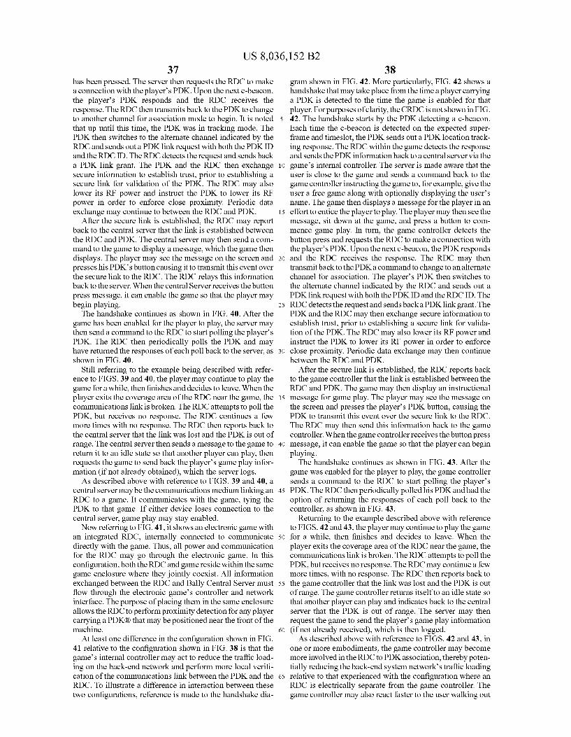
US 8,036,152 B2 37
has been pressed. The server then requests the RDC to make a connection with the player's PDK. Upon the next c-beacon, the player's PDK responds and the RDC receives the response. The RDC then transmits back to the PDK to change to another channel for association mode to begin. It is noted that up until this time, the PDK was in tracking mode. The PDK then switches to the alternate channel indicated by the RDC and sends out a PDKlink request with both the PDKID and the RDC ID. The RDC detects the request and sends back a PDK link grant. The PDK and the RDC then exchange secure information to establish trust, prior to establishing a secure link for validation of the PDK. The RDC may also lower its RF power and instruct the PDK to lower its RF power in order to enforce close proximity. Periodic data exchange may continue to between the RDC and PDK.
After the secure link is established, the RDC may report back to the central server that the link is established between the RDC and PDK. The central server may then send a com mand to the game to display a message, which the game then displays. The player may see the message on the screen and presses his PDK's button causing it to transmit this event over the secure link to the RDC. The RDC relays this information back to the server. When the central Server receives the button press message, it can enable the game so that the player may begin playing.
The handshake continues as shown in FIG. 40. After the game has been enabled for the player to play, the server may then send a command to the RDC to start polling the players PDK. The RDC then periodically polls the PDK and may have returned the responses of each poll back to the server, as shown in FIG. 40.
Still referring to the example being described with refer ence to FIGS. 39 and 40, the player may continue to play the game for a while, then finishes and decides to leave. When the player exits the coverage area of the RDC near the game, the communications link is broken. The RDC attempts to poll the PDK, but receives no response. The RDC continues a few more times with no response. The RDC then reports back to the central server that the link was lost and the PDK is out of range. The central server then sends a message to the game to return it to an idle state so that another player can play, then requests the game to send back the player's game play infor mation (if not already obtained), which the server logs. As described above with reference to FIGS. 39 and 40, a
central server may be the communications medium linking an RDC to a game. It communicates with the game, tying the PDK to that game. If either device loses connection to the central server, game play may stay enabled. Now referring to FIG. 41, it shows an electronic game with
an integrated RDC, internally connected to communicate directly with the game. Thus, all power and communication for the RDC may go through the electronic game. In this configuration, both the RDC and game reside within the same game enclosure where they jointly coexist. All information exchanged between the RDC and Bally Central Server must flow through the electronic game's controller and network interface. The purpose of placing them in the same enclosure allows the RDC to perform proximity detection for any player carrying a PDKR) that may be positioned near the front of the machine. At least one difference in the configuration shown in FIG.
41 relative to the configuration shown in FIG. 38 is that the game's internal controller may act to reduce the traffic load ing on the back-end network and perform more local verifi cation of the communications link between the PDK and the RDC. To illustrate a difference in interaction between these two configurations, reference is made to the handshake dia
5
10
15
25
30
35
40
45
50
55
60
65
38 gram shown in FIG. 42. More particularly, FIG. 42 shows a handshake that may take place from the time a player carrying a PDK is detected to the time the game is enabled for that player. For purposes of clarity, the CRDC is not shown in FIG. 42. The handshake starts by the PDK detecting a c-beacon. Each time the c-beacon is detected on the expected Super frame and timeslot, the PDKsends out a PDK location track ing response. The RDC within the game detects the response and sends the PDK information back to a central server via the game's internal controller. The server is made aware that the user is close to the game and sends a command back to the game controller instructing the game to, for example, give the user a free game along with optionally displaying the user's name. The game then displays a message for the player in an effort to entice the player to play. The player may then see the message, sit down at the game, and press a button to com mence game play. In turn, the game controller detects the button press and requests the RDC to make a connection with the player's PDK. Upon the next c-beacon, the PDK responds and the RDC receives the response. The RDC may then transmit back to the PDKa command to change to an alternate channel for association. The player's PDK then switches to the alternate channel indicated by the RDC and sends out a PDKlink request with both the PDKID and the RDC ID. The RDC detects the request and sends back a PDKlink grant. The PDK and the RDC may then exchange secure information to establish trust, prior to establishing a secure link for valida tion of the PDK. The RDC may also lower its RF power and instruct the PDK to lower its RF power in order to enforce close proximity. Periodic data exchange may then continue between the RDC and PDK.
After the secure link is established, the RDC reports back to the game controller that the link is established between the RDC and PDK. The game may then display an instructional message for game play. The player may see the message on the screen and presses the player's PDK button, causing the PDK to transmit this event over the secure link to the RDC. The RDC may then send this information back to the game controller. When the game controller receives the button press message, it can enable the game so that the player can begin playing. The handshake continues as shown in FIG. 43. After the
game was enabled for the player to play, the game controller sends a command to the RDC to start polling the player's PDK. The RDC then periodically polled his PDK and had the option of returning the responses of each poll back to the controller, as shown in FIG. 43.
Returning to the example described above with reference to FIGS. 42 and 43, the player may continue to play the game for a while, then finishes and decides to leave. When the player exits the coverage area of the RDC near the game, the communications link is broken. The RDC attempts to poll the PDK, but receives no response. The RDC may continue a few more times, with no response. The RDC then reports back to the game controller that the link was lost and the PDK is out of range. The game controller returns itself to an idle state so that another player can play and indicates back to the central server that the PDK is out of range. The server may then request the game to send the player's game play information (if not already received), which is then logged. As described above with reference to FIGS. 42 and 43, in
one or more embodiments, the game controller may become more involved in the RDC to PDKassociation, thereby poten tially reducing the back-end system network's traffic loading relative to that experienced with the configuration where an RDC is electrically separate from the game controller. The game controller may also react faster to the user walking out
US 8,036,152 B2 39
of range and may not require any response from the server in order to maintain the link. It is further noted that abroken link between the central server, game controller, and RDC may not result in any loss of any interaction between the RDC and the game controller.
While the invention has been described with respect to a limited number of embodiments, those skilled in the art, having benefit of the above description, will appreciate that other embodiments may be devised which do not depart from the scope of the present invention as described herein. Accordingly, the scope of the present invention should be limited only by the appended claims. What is claimed is: 1. An apparatus, comprising: a wireless transceiver having an active mode in which power is consumed, and a sleep mode in which power is conserved;
a timer operatively coupled to the wireless transceiver used to indicate when to switch from sleep mode to active mode based on time slot assignment information received by the wireless transceiver; and
processing circuitry operatively coupled to the wireless transceiver and the timer, the processing circuitry arranged to switch the wireless transceiver from the sleep mode to the active mode in response to input from the timer, the processing circuitry also arranged to moni tor a first channel for a beacon during the active mode and, if no beacon is detected, increasing a channel num ber to a second channel and resetting the timer.
2. The apparatus of claim 1, wherein the timer is set to an amount of time until a next time slot.
3. The apparatus of claim 1, wherein an amount of time the wireless transceiver is in the active mode is dynamically adjustable based on the time slot assignment information.
4. The apparatus of claim 1, wherein the wireless trans ceiver comprises an RF interface.
5. The apparatus of claim 1, wherein the wireless trans ceiver does not wirelessly communicate data during the sleep mode.
6. The apparatus of claim 1, further comprising: a battery operatively connected to the wireless transceiver. 7. A method of facilitating data exchange, comprising: wirelessly receiving information assigning a time slot for a
portable client device to wirelessly communicate data; placing the wireless transceiver in a sleep mode for a pre
determined amount of time; setting a timer to indicate when to Switch from sleep mode
to an active mode based on the time slot assignment information; and
activating the wireless transceiver from the sleep mode at a beginning of the time slot in response to input from the timer;
monitoring a first channel for a beacon; if no beacon is detected, increasing a channel number to a
second channel; and resetting the timer. 8. The method of claim 7, further comprising: powering the device with a battery operatively connected
to a wireless transceiver.
10
15
25
30
35
40
45
50
55
40 9. The method of claim 7, wherein the wireless transceiver
consumes less power when in the sleep mode than when activated.
10. The method of claim 7, further comprising: setting the timer to indicate the beginning of the time slot. 11. The method of claim 7, further comprising: setting the timer to an amount of time until a next time slot. 12. The method of claim 7, wherein the wirelessly received
information comprises a mask for application to a bit field stored in the client device, wherein the timeslot is determined based on the masked bit field.
13. The method of claim 7, further comprising: applying a mask to a bit field stored in the client device,
wherein activating the wireless transceiver from the sleep mode is dependent on the masked bit field.
14. The method of claim 7, further comprising: setting the timer to indicate a beginning of the sleep mode. 15. A system, comprising: a network device arranged to wirelessly broadcast syn
chronization information in a wireless coverage range; and
a portable client device arranged to wirelessly receive the synchronization information during an active state, wherein the synchronization information indicates a time slot for the client device to wirelessly communicate data, wherein the client device utilizes a timer to indicate a time outside of the time slot, and wherein the client device enters a sleep mode in response to input from the timer, and wherein the client device monitors a first channel for a beacon during the active state and, if no beacon is detected, increases a channel number to a second channel and resets the timer.
16. The system of claim 15, wherein the client device comprises a wireless transceiver that is deactivated from wirelessly communicating data when in the sleep mode.
17. The system of claim 15, wherein the synchronization information comprises a mask for application to a bit field stored in the client device.
18. The system of claim 17, wherein the time slot is depen dent on the masked bit field.
19. The system of claim 15, wherein a duration of the sleep mode is dependent on the synchronization information broad cast by the network device.
20. The system of claim 15, whereina duration of the sleep mode is dependent on a power consumption setting deter mined by at least one of the network device and the client device.
21. The apparatus of claim 1, wherein in response to detect ing the beacon, the processing circuitry checks for a network identification.
22. The method of claim 7, further comprising the steps of: detecting the beacon; and checking for a network identification. 23. The system of claim 15, wherein in response to detect
ing the beacon, the client device checks for a network iden tification.