(12) united states patent (10) patent no.: us 7,898,478 b2 · · 2017-11-06analog beam forming...
TRANSCRIPT

US0078.98478B2
(12) United States Patent (10) Patent No.: US 7,898,478 B2 Niu et al. (45) Date of Patent: *Mar. 1, 2011
(54) METHOD AND SYSTEM FOR ANALOG 7,161,534 B2 1/2007 Tsai et al. BEAMFORMING IN WIRELESS 7.239,893 B2 * 7/2007 Yang .......................... 455,561 COMMUNICATION SYSTEMS 7.312,750 B2 12/2007 Mao et al.
7.342,535 B2 * 3/2008 Ann et al. ................... 342/.377 (75) Inventors: Huaning Niu Sunnyvale, CA (US) 7.450,659 B2 11/2008 Corredoura et al.
Es Mility, SS 2002/0122498 A1* 9/2002 Dogan ........................ 375,259 Iu Ngo, San Franc1sco, 2002/0128027 A1 9/2002 Wong et al.
(73) Assignee: Samsung Electronics Co., Ltd., Suwon 2002/014.7032 A1* 10, 2002 Yoon et al. .................. 455,562 (KR)
(*) Notice: Subject to any disclaimer, the term of this patent is extended or adjusted under 35 (Continued) U.S.C. 154(b) by 123 days. FOREIGN PATENT DOCUMENTS
This patent is Subject to a terminal dis- JP 2004140642 A2 5, 2004 Ca10.
(21) Appl. No.: 11/881,978 OTHER PUBLICATIONS
(22) Filed: Jul. 30, 2007 WirelessHD Specification draft version 0.7. WirelessHD consortium,
(65) Prior Publication Data Feb. 2007.
US 2008/0204319 A1 Aug. 28, 2008 (Continued)
Related U.S. Application Data Primary Examiner Dao L. Phan 74) Attorney, Agent, or Firm—Kenneth L. Sherman, Esq.; 6O) P 1 application No. 60904,030 filed on Feb. y, Agent, , ESC.
(60) Type applicauon No U3 U, Illed on Fe Michael Zarrabian, Esq.; Myers Andras Sherman & s Zarrabian LLP
(51) Int. Cl. H01O 3/00 (2006.01) (57) ABSTRACT H01O 3/12 (2006.01)
(52) U.S. Cl. ........................ 342/377; 342/373; 342/374 (58) Field of Classification Search ......... 42,372-374. A method and system for analog beamforning in a wireless
342/.377: 375/259: 455/276.1. 277.1562.1 system is provided. Analog beam forming involves perform See application file for com lete search histo s ing an iterative beam acquisition process based on beam
pp p ry. search training, determining transmit and receive beam form (56) References Cited ing vectors including phase weighting coefficients, based on
U.S. PATENT DOCUMENTS
5,955,991 A 9, 1999 Kawakubo 6,590,532 B1 7/2003 Ogawa et al. 6,795,392 B1 9, 2004 Li et al. 7,039,370 B2 5/2006 Laroia et al.
Transmitter
Enter beanforming acquisition stage
22
2
the iterative beam acquisition process. Each iteration includes estimating the receive and transmit beam forming coefficients alternatively, until the receive and transmit beam forming coefficients converge.
35 Claims, 6 Drawing Sheets
Receive
23
Transmit using current w --- Receive training sequence and estimate receive beamforming vector w.
Receive training sequence and estimate transmit beanforming vector w Transmit using current beanforming vector w.
is sed Yes
27
24 t
28 Use w; as the Tx beamforming vector Usew to find Rx beamforming vector
TKBeamforming acquired; Enter data transmission mode 9A
Rx Bearnforming acquired; 29B Enter data receiving mode

US 7,898.478 B2 Page 2
U.S. PATENT DOCUMENTS
2003/02O1936 A1 2005/0276347 A1 2006, O104382 A1* 2006/0234645 A1 2006/0248429 A1 2007. O1894.12 A1 2007/0205943 A1 2008/0101493 A1
10/2003 Kim 12/2005 Mujtaba et al. 5/2006 Yang et al. .................. 375,267
10, 2006 Lin et al. 11/2006 Grandhi et al. 8, 2007 Xia et al. 9/2007 Nassiri-Toussi et al. 5, 2008 Niu et al.
2008/O108390 A1* 5/2008 Yoon et al. .................. 455,561 2008/0134254 A1 6, 2008 Xia et al. 2008/O144751 A1* 6/2008 Xia et al. .................... 375/347 2009/0033555 A1 2009/012 1935 A1 2009/0233556 A1
OTHER PUBLICATIONS
“Draft Amendment to Standard for Information Technology-Tele communications and information exchange between systems-Local and metropolitan area networks-Specific requirements-Part 11: Wireless LAN Medium Access Control (MAC) and Physical Layer (PHY) specifications: Enhancements for Higher Throughput.” IEEE P802.11n/D1.0, Mar. 2006). Van Veen, B.D.; and Buckley, K.M.. “Beamforming: a versatile approach to spatial filtering”. ASSP Magazine, IEEE, vol. 5, Iss. 2. Apr. 1988, pp. 4-24. U.S. Appl. No. 1 1/899,286, filed Sep. 5, 2007, Pengfei Xia et al. Butler, J. and Lowe, R., “Beam-Forming Matrix Simplifies Design of Electronically Scanned Antennas'. Electronic Design, pp. 170-173, Apr. 12, 1961. Hansen, R.C., “Phased Array Antennas', pp. 1-507, John Wiley and Sons, New York, 1998. Coffey, S., et al., “Joint Proposal: High throughput extension to the 802.11 Standard: PHY', doc.: IEEE 802.11-05/1102r4, draft pro posal, Jan. 2006, pp. 1-82. Niu, H. and Ngo, C., “Beamforming for Space-Time Coded IEEE 802.11n System with Known Fading Correlations', in Proceeding of 90th Asilomar Conference on Signals, Systems and Computers, Pacific Grove, CA, Nov. 2005.
2/2009 Niu et al. 5, 2009 Xia et al. 9, 2009 Xia et al.
U.S. Non-Final Office Action for U.S. Appl. No. 1 1/890.207 mailed Jun. 23, 2008. U.S. Final Office Action for U.S. Appl. No. 1 1/890,207 mailed Nov. 24, 2008. Advisory Action for U.S. Appl. No. 1 1/890,207 mailed Mar. 2, 2009. U.S. Non-Final Office Action for U.S. Appl. No. 1 1/890.207 mailed Apr. 6, 2009. G. Stuber, J. Barry, S. McLaughlin, Y. Li, M.Ingram and T. Pratt, “Broadband MIMO-OFDM wireless communications, 'Proceedings of the IEEE, vol. 92, No. 2, pp. 271-294, Feb. 2004. High-Definition Multimedia (HDMI) Specification, Version 1.2, Aug. 22, 2005, pp. 1-214. IEEE Std 802.15.3, “Wireless Medium Access Control (MAC) and Physical Layer (PHY) Specifications for High Rate Wireless Per sonal Areas Networks (WPANs). 2003, pp. 1-324. J. De Los Santos, "MEMS-Based Microwave Circuits and Systems, Introduction to Microelectromechanical (MEM) Microwave Sys tems”, Artech House, p. 167-168 and 193, 1999. S. Furrer et al., "Bounds on the ergodic capacity of training-based multiple-antenna systems'. Internal Symposium on Information Theory, p. 780-784, Sep. 2005. S. Buzzi et al., Performance of iterative data detection and channel estimation for single-antenna and multiple-antennas wireless com munications, IEEE Transactions on Vehicular Technology, vol.53(4), p. 1085-1104, Jun 2004. U.S. Non-final Office Action for U.S. Appl. No. 1 1/899,286 mailed Sep. 24, 2009. Scintera Networks, "Advanced Signal Processing Platform.” Sep. 2003, pp. 1-9. United States. Razavi, B., "Challenges in Portable RF Transceiver Design.” Circuits & Devices, IEEE, Sep. 2006, pp. 12-25, United States. U.S. Non-Final Office Action for U.S. Appl. No. 1 1/706,942 mailed Oct. 15, 2009. U.S. Final Office Action for U.S. Appl. No. 1 1/890,207 mailed Oct. 26, 2009. U.S. Notice of Allowance for U.S. Appl. No. 1 1/890.207 mailed Jan. 11, 2010. U.S. Notice of Allowance for U.S. Appl. No. 1 1/899,286 mailed Jan. 21, 2010.
* cited by examiner

US 7,898.478 B2 U.S. Patent

US 7,898.478 B2 Sheet 2 of 6 Mar. 1, 2011 U.S. Patent
J3A1903 YI
Iz^ IZ
ON

US 7,898.478 B2 Sheet 3 of 6 Mar. 1, 2011 U.S. Patent
Timing Recovery Stage #1
Opt. Delay Est Stage #2
RXBV Training Stage #3
STA2
FIG. 4
U.S. Patent Mar. 1, 2011 Sheet 5 of 6 US 7,898.478 B2
STA1 STA2
FIG. 5

US 7,898.478 B2 Sheet 6 of 6 Mar. 1, 2011 U.S. Patent
- - - - - - - - - - - - - - - - - - - - - -nings---------------------------------------------------------------#--------- Jørg?[duuv3Se?A
A1
9 (018

US 7,898,478 B2 1.
METHOD AND SYSTEM FOR ANALOG BEAMFORMING IN WIRELESS COMMUNICATION SYSTEMS
RELATED APPLICATION
This application claims priority from U.S. Provisional Patent Application Ser. No. 60/904,030 filed on Feb. 28, 2007, incorporated herein by reference.
FIELD OF THE INVENTION
The present invention relates to wireless networks, and in particular to beam forming transmissions in wireless net works.
BACKGROUND OF THE INVENTION
High speed wireless communications over high frequency bands Suffer severe path loss, and thus require high gain antennas. Existing methods to enable high antenna gain include use of directional antennas and use of antenna arrays. The latter is often preferred because a beam direction can be adaptively steered in an electronic manner. Antenna array beam forming (BF) provides increased signal quality due to high directional antenna gain. Further, steering the transmit ted signal in a dedicated direction extends the communication range. A beam forming operation can be implemented in an ana
log domain, after a digital-to-analog converter (D/A or DAC) at a transmit station and before an analog-to-digital converter (A/D or ADC) at a receive station. Beamforming can also be implemented in the digital domain, before the D/A at the transmit station and after the A/D at the receive station.
Digital beam forming is proposed in the 802.11n draft specification (“Draft Amendment to Standard for Information Technology-Telecommunications and information exchange between systems-Local and metropolitan area networks-Spe cific requirements-Part 11: Wireless LAN Medium Access Control (MAC) and Physical Layer (PHY) specifications: Enhancements for Higher Throughput.” IEEE P802.11n/ D1.0, March 2006). Digital beam forming using eigen-de composition is an optimal approach, providing the highest throughput and reliability.
However, digital beam forming is a costly scheme because it requires the same number of radio frequency (RF) chains as the number of antennas in an antenna array. Analog beam forming, on the other hand, requires one RF chain for an antenna array. For applications such as 60 GHz frequency band wireless networks (e.g., wireless high-definition or WirelessHD), since the bandwidth is high (the spectrum effi ciency is not high), reliable transmission of one data stream via an RF chain over an antenna array is satisfactory. Analog beam forming provides a simple solution to reduce the RF chain cost while maintaining the array gain.
In a related iterative analog beam forming scheme, a beam search protocol is based on explicit feedback of a transmit beam forming vector between a first station STA1 (a BF trans mitter) and a second station STA2 (a BF receiver). To estimate the optimal transmit beam forming vector, the transmitteruses Switch beam forming and Switches across all possible beams. This approach is useful in finding a transmit beam forming vector in the initial stage of a beam forming search protocol. However, ifa useful initial estimate of the receive beam form ing vector is required, then Such an approach cannot be applied because Switching across all transmit beams cannot
10
15
25
30
35
40
45
50
55
60
65
2 be performed for estimating the optimum receive beam form ing vector, while maintaining a Sufficient link budget.
BRIEF SUMMARY OF THE INVENTION
The present invention provides a method and system for analog beam forming in wireless communication systems. In one embodiment Such analog beam forming includes an itera tive process involving a transmitter and a receiver.
Based on beam search training, an iterative beam acquisi tion process is performed for finding optimized transmit and receive beam forming vectors including phase weighting coefficients.
Each iteration involves estimating the receive and transmit beam forming coefficients alternatively, until the receive and transmit beam forming coefficients converge.
These and other features, aspects and advantages of the present invention will become understood with reference to the following description, appended claims and accompany ing figures.
BRIEF DESCRIPTION OF THE DRAWINGS
FIG. 1 shows a functional block diagram of an analog beam forming wireless system implementing an embodiment of the present invention.
FIG. 2 shows an example iterative beam acquisition pro tocol for obtaining beam forming vectors for analog adaptive beam forming between two wireless transceivers, according to the present invention.
FIG.3 shows an example beam search process for wireless stations according to the present invention.
FIG. 4 shows an example message exchange process between wireless stations, according to the present invention.
FIG.5 shows an example beam tracking message exchange sequence in a beam tracking process, according to the present invention.
FIG. 6 shows an example implementation of an implicit beam forming frameworkin wireless system for adaptive ana log beam forming, according to the present invention.
DETAILED DESCRIPTION OF THE INVENTION
The present invention provides a method and system for analog beam forming in a wireless communication system including wireless stations that can transmit and/or receive information. In one embodiment Such analog beam forming includes an iterative process involving a transmitter and a receiver.
Before communication of actual payload data, a certain sequence is transmitted from a transmitting station (transmit ter) to a receiving station (receiver) for performing channel estimation and beam estimation. An iterative training proto col and an iterative beam searching process for analog beam forming are performed. The iterative training protocol allows determining a beam forming vector (BV) for analog adaptive beam forming. At the end of the iterative training protocol, the iterative beam search is also completed and beam forming is carried out simultaneously at the transmitter side and the receiverside. This allows for adaptive beam forming wherein the BV is adapted according to communication channel varia tions. Adaptive beam forming is also more versatile in Sup pressing interference and in extending the communication range. An example implementation of the present invention in a
WirelessHD beam forming 60 GHz, communication system is described below. WirelessHD is an industry-led effort to
US 7,898,478 B2 3
define a wireless digital network interface specification for wireless high-definition digital signal transmission on the 60 GHZ frequency band, e.g., for consumer electronics products. As those skilled in the art of wireless beam forming will recognize, other implementations are possible and the teach ings of the present invention are applicable to other wireless communication systems as well.
FIG. 1 shows an analog beam forming wireless system 10, such as a WirelessHD system including two beam forming stations 11 and 12 (BF stations STA1 and STA2) providing an implicit beam forming framework, according to an embodi ment of the present invention. The stations 11 and 12 com prise transceivers that include antenna arrays 13a and 13b. respectively. The transmit (TX) function of the station 11 includes an
inverse Fast Fourier Transform (IFFT) 14 which mainly con verts a baseband signal from the frequency domain into a time domain digital signal. The digital signal is then converted into an analog waveform by a D/A function of an RF chain 15, and is then transmitted to the station 12 after analog beam forming by an analog TX BF function 16.
The receive (RX) function of the station 12 includes an analog RX BF function 17 which cooperatively with the analog TX BF function 16 provides analog beam forming. The analog output signal from the analog RX BF function 17 is converted to a digital signal in an RF chain 18, and then converted to the frequency baseband signal by an FFT 19. A symmetric transceiver structure is assumed for training,
wherein both the transmitter and receiver are able to send and receive in high speed at the 60 GHz frequency band. Trans mission and reception take place in a time division duplexing (TDD) manner, wherein channel reciprocity can be used to reduce the training overhead. Normally, channel calibration is required to assure the channel reciprocity. An adaptive beam forming process is implemented by the
TX BF function 16 and the RX BF function 17. The adaptive beam forming process includes beam searching and beam tracking procedures for implicit beam forming. An iterative beam searching process and a beam tracking sequence exchange process, utilize the channel reciprocity to reduce the training overhead and improve system throughput. The beam tracking procedure is similar to the beam search proce dure and is based on a one-time training of each transceiver.
Specifically, transmit and receive beam forming coeffi cients for beam forming vectors are obtained iteratively. In one example, each iteration involves estimating interim receive and transmit beam forming coefficients alternatively, until the receive and transmit beam forming coefficients con Verge in a terminating iteration, providing final (optimum) beam forming vectors.
In one implementation, described herein below, a transmit ter BV (i.e., antenna weighting coefficient) training is per formed over a reverse multiple-input-multiple-output (MIMO) channel (e.g., from the RX 12 to the TX 11), while receiver BV training takes place over the forward MIMO channel (e.g., from the TX 11 to the RX 12). An estimation of an optimal transmitter BV is performed at the beam forming transmitter 11, and estimation of an optimal receiver BV is performed at the beam forming receiver 12. As a result, there is no need to exchange the estimated BV, thereby reducing the signaling overhead. The adaptive beam forming protocols described herein can be used to establish a high rate (HRP) data link or a low rate (LRP) data link. Training and Beam Searching
During the entire communication period, a wireless station may experience three different states: a beam-lost state, a
10
15
25
30
35
40
45
50
55
60
65
4 beam-deviated State and a beam-acquired State. In a beam lost state, beam forming is completely lost, calling for a new search of beam forming vectors. In a beam-deviated State, beam forming is slightly deviated, generally calling for a beam tracking operation. In a beam-acquired State beam forming is optimally acquired and data communications may follow. A beam searching (beam acquisition) process is initiated
by the transmitter, although the receiver may send a request to the transmitter in order to initiate the acquisition process. In one scenario, the station 11 serves as the transmitter or signal Source and the station 12 serves as the receiver or signal sink. Also, without loss of generality, a transmit beam is initiated by a properly chosenbeamforming vector w, FIG.2 shows an example iterative beam acquisition protocol 20 for obtaining beam forming vectors for analog adaptive beam forming between two wireless transceivers (e.g., stations 11, 12 in FIG. 1), by estimating interim receive and transmit beam forming coefficients alternatively until convergence, accord ing to the present invention. The protocol 20 includes the steps of:
Step 21: A transceiver station STA1 enters the transmit mode as a transmitter (TX).
Step 22: Transmitter transmits a training sequence using the current transmit beam forming vector w, .
Step 23: The training sequence originating from the trans mitteris received at a transceiver station STA2 operating now in a receive mode as a receiver (RX), and the received training sequence is used to estimate a receive beam forming vector w. Preferably, the receiver com putes an optimal receive beamforming vector w.
Step 24: The receiver then switches to a transmit mode and transmits a training sequence using a beam forming vec tor that is the same as the current receive beam forming vector w.
Step 25: The training sequence originating from station STA2 is then received at the station STA1 operating now in receive mode, and the received training sequence is used to estimate a transmit beam forming vector w.
Step 26: The above steps are repeated N. times before converging to the final transmit and receive beam form ing vectors, indicating that they are optimized. In each iteration step, it is determined if final transmit and receive beam forming vectors have converged and a beam-acquired State is achieved. If not, the process pro ceeds to step 22, otherwise the process proceeds to step 27.
Step 27: The station STA1 now operating in transmit mode uses the beam forming vector w, as a TX beam forming vector and transmits the TX beam forming training sequence to the station STA2.
Step 28: The station STA2 now operating in receive mode uses the beam forming training sequence to determine a final RX beam forming vector.
Step 29A. A final TX beam forming vector having been acquired, the station STA1 can enter data transmission mode using the TX beam forming vector.
Step 29B: A final RX beam forming vector having been acquired, the station STA2 can enter data receiving mode using the RX beam forming vector.
In estimating the transmit beam forming vector w, the sta tion STA1 operates in receive mode while the station STA2 operates in transmit mode. Such an estimation method takes advantage of TDD-based wireless communication. Calibra tion may be used to compensate for channel mismatch due to asymmetric RF circuitry.

US 7,898,478 B2 5
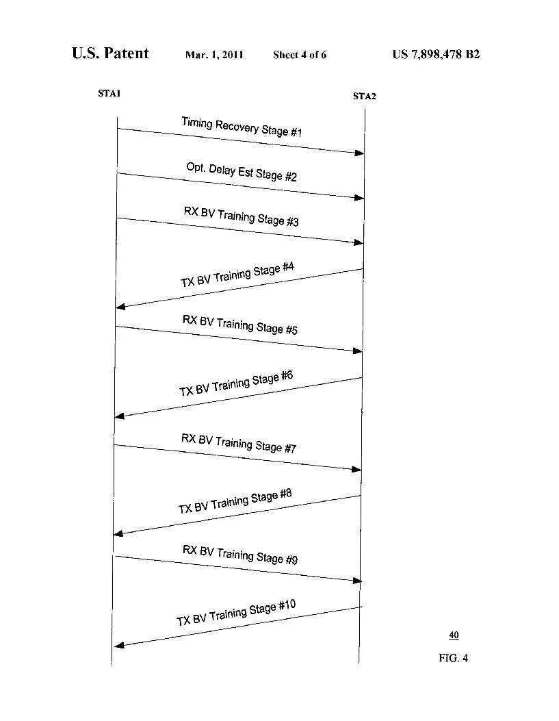
Beam Search Stages FIG. 3 shows an example beam search process 30 for
stations STA1 and STA2, including multiple stages using N-4 iterations, according to a corresponding message exchange process 40 for stations STA1 and STA2 as illus trated in FIG. 4.
Stage 1 (Timing recovery with TX BV): This training period is used by the beam forming receiver to detect the beam search timing.
Stage 2 (Delay estimation with TX BV): This training period is used by the beam forming receiver to estimate the arrival time of the optimal beam.
During stages 1 and 2, the beam forming transmitter STA1 sends a specific training sequence while the transmitter BV is fixed to an arbitrary phase vector. The receiver STA2 receives the training sequence while the receiver BV switches between phase vectors within a set of weighting vectors spanning the entire space, typically an orthogonal matrix Such as a Hard mard matrix or Fourier matrix. The following 2 stages are repeated N
1, 2, . . . . N) for beam searching: Stage3+2i (RX BV training with TXBV3+2i): During this
period, the beam forming transmitter STA1 sends a spe cific training sequence to STA2 while the transmitter BV is fixed to the current transmit beam forming vector. The beam forming receive BV switches between phase vec tors within the weight vector set used in stages 1 and 2. following a given order. The receiver STA2 uses the received sequence to estimate the optimum receiver BV W.
Stage 4+2i (TXBV training): During this period, the beam forming receiver STA2 sends a specific training sequence to STA1 while the BV is set to w, computed from the previous stage. The beam forming transmitter STA1 uses the received sequence to estimate the opti mum transmit BV w, which is used in the next RX BV training stage.
The above beam search steps are described in further detail below.
Beam Search Sequence at STA1 and STA2 The beam search training sequence uses a pseudo random
sequence (PRN). The sequence can be any random sequence with constant amplitude and good autocorrelation properties, such as an M-sequence. The PRN is modulated by digital modulation, such as Binary Phase Shift Keying (BPSK). Quadrature Phase Shift Keying (QPSK). Differential Binary Phase Shift Keying (DBPSK) or Offset Quadrature Phase Shift Keying (OQPSK), for transmission. The training sequence length depends on the actual link budget. A longer length is needed for a tight link budget. A link budget accounts for all of the gains and losses from the transmitter, through the medium (free space, cable, waveguide, fiber, etc.) to the receiver in a wireless communication system. The receive beam forming estimation protocol herein takes advan tage of receiver side antenna diversity and achieves a link budget for implicit beam forming over wireless channels.
times (I-0, ife
Beam Search Stage 1 (Timing Recovery) Training Sequence The stage 1 training sequence is used for automatic gain
control (AGC) and timing recovery estimation. The transmit ter STA1 BV is fixed to an arbitrary vector while the receiver STA2 BV is changed over the AGC and timing recovery fields. The BV is switched between phase vectors within a set of weight vectors spanning the whole space, typically an orthogonal matrix Such as a Hardmard matrix or Fourier matrix.
10
15
25
30
35
40
45
50
55
60
65
6 Beam Search Stage 2 (Delay Estimation) Training Sequence The stage 2 training sequence also includes an AGC and
delay estimation fields. The transmitter STA1 BV is chosen to be the same phase vector as that in stage 1. The receiver STA2 BV is changed over the delay estimation field. The BV is switched between phase vectors within a same set of weight vectors as stage 1. Beam Search Stage 3 (RXBV Estimation)Training Sequence
During stage 3, the transmitter STA1 BV is chosen to be the same phase vector as that in stages 1 and 2. The receiver STA2 BV switches between phase vectors within a same set of weight vectors as stage 1. Beam Search Stage 4 (TXBV Estimation) Training Sequence The beam forming receiver STA2 serves as the transmitter
at this stage with the transmit BV set to the phase vector calculated from stage 3. The receiver (beam forming transmit ter) STA1 BV switches between phase vectors within a same set of weight vectors as stage 1. Beam Search Stages 5, 7, 9 (RX BV Estimation) Training Sequence
During stages 5, 7 and 9, the transmitter STA1 BV is set to the phase vector calculated from stages 4, 6 and 8, respec tively. The receiver STA2BV switches between phase vectors within a same set of weight vectors as stage 1. Beam Search Stages 6, 8, 10 (TX BV Estimation) Training Sequence
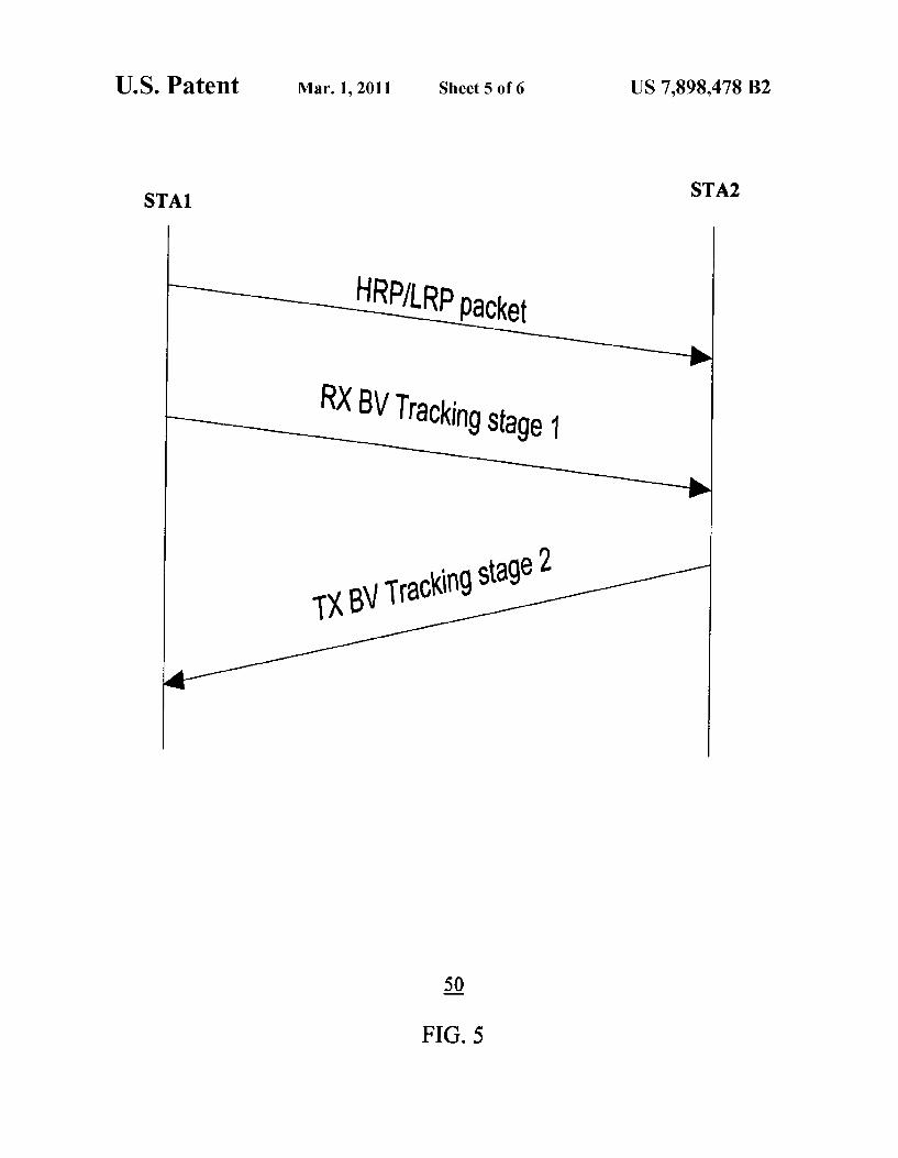
During stages 6, 8 and 10, the receiver STA2 BV is set to the phase vector calculated from stages 5, 7 and 9, respec tively. The receiver (beam forming transmitter) STA1 BV Switches between phase vectors within a same set of weight vectors as stage 1. Beam Tracking The beam tracking process includes two stages according
to the beam tracking message exchange sequence 50 in FIG. 5. Beam tracking is used in a beam-deviated State according to the following two stages:
Stage 1 (RX BV tracking): During this period, the beam forming transmitter STA1 sends a specific training sequence while the transmitter BV is fixed to the current transmit beam forming. The beam forming receive BV switches between phase vectors within the weight vector set used in stages 1 and 2, following a given order. The receiver STA2uses the received sequence to estimate the optimum receiver BV w,
Stage 2 (TX BV tracking): During this period, the beam forming receiver STA2 sends a specific training sequence while the BV is set to w, calculated from the previous stage. The beam forming transmitter STA1 uses the received sequence to estimate the optimum transmit
Implementation FIG. 6 shows an example implementation of the implicit
beam forming framework in FIG. 1 as a wireless system 60 providing adaptive analog beam forming, according to the present invention. The wireless system 60 involves a trans ceiver including a transmitter (TX) and a receiver (RX) with multiple antennas, shown functioning during a training sequence for implicit determination of transmit and receive beam forming vectors v and w, respectively.
In this example, v-Iv, V. . . . , VI is a collection of transmit analog beam forming weighting coefficients in vec tor form, andw-w, w, ..., w" is a collection of receive analog beam forming weighting coefficients in vector form,
US 7,898,478 B2 7
wherein N is the number of transmit antennas and M is the number of receive antennas (N and M need not be the same). The transmitter includes digital functions and analog func
tions. The digital functions include a PN sequence generator function 61, a modulator function 62, a DAC 63 and a con troller function 64. The analog functions include a mixer function 65, a phase shifter array function 66 and a power amplifier array function 67 driving N transmit antennas 69a. The receiver also includes digital functions and analog
functions. The analog functions include a power amplifier array 68 driving M receive antennas 69b, a phase shifter array function 70 and a combiner function 71. The digital functions include a mixer function 72, an ADC function 73, a timing estimation function 74, a delay estimation function 75, a beam forming vector (BV) estimation function 76 and a con troller function 77.
Before communication of actual payload data, a certain training sequence is transmitted from the transmitter. During training, the PN sequence generator 61 in generates a PN sequence specified with a particular pattern. The modulator 62 modulates the PN sequence with a particular waveform (e.g., BPSK, QPSK, DBPSK or OQPSK (offset QPSK)) to generate a baseband signal. The DAC 63 converts the modu lated signal to an analog baseband signal, wherein the mixer 65 up-converts the baseband signal to an RF. The controller 64 controls both the PN sequence generator 61 to generate a desirable PN sequence at each stage, and also controls the phase value (transmit beam forming vectorv) in the phase shifter 65 for transmission of the sequence via the antenna array 69a as driven by the amplifier array 67.
During training, the receiver receives the training sequence via the antennas 69b, driven by the power amplifier array 68. The controller 77 controls the phase value (receive beam forming vector w) in the phase shifter 70, for generating signals that are combined by the combiner 71 into an RF signal. The mixer 72 down-converts the RF signal to an ana log baseband signal, and the ADC 73 converts the analog baseband signal into a digital signal. The time estimation function 74 implements stage 1 of the beam search process 30 described above (FIG.3) and the delay estimation function 75 implements stage 2 of the beam search process 30 described above. The BV estimation function 76 determines optimal beam forming vectors (v, w) based on the received training sequence according to the iterative beam acquisition process 20 described above (FIG. 2). The resulting beam forming vectors (v,w) are used to steer
the transmit phase shifts in the transmission stages (i.e., the phase shifter array and power amplifier array) for communi cation of actual payload data.
Although FIG. 6 shows separate phase shifters and anten nas for transmitter and receiver, in another example, the same set of phase shifters and antennas are reused for the trans ceiver by serving functions for transmitter or receiver at dif ferent time slots.
Accordingly, the present invention provides analog beam forming which involve iterative beam searching and beam tracking for implicit beam forming, using a receive beam forming estimation protocol based on receiver side antenna diversity and a link budget. The present invention enables estimating the transmit and receive beam forming vector Such that the transmitter does not require final or interim receive beam forming vectors, and the receiver does not require final or interim transmit beam forming vectors. As is known to those skilled in the art, the aforementioned
example architectures described above, according to the present invention, can be implemented in many ways, such as program instructions for execution by a processor, as logic
10
15
25
30
35
40
45
50
55
60
65
8 circuits, as an application specific integrated circuit, as firm ware, etc. The present invention has been described in con siderable detail with reference to certain preferred versions thereof; however, other versions are possible. Therefore, the spirit and scope of the appended claims should not be limited to the description of the preferred versions contained herein. What is claimed is: 1. A method of analog beam forming in a wireless system
including transceivers with multiple antennas, comprising the steps of:
performing an iterative beam acquisition process based on beam search training; and
determining optimized transmit and receive beam forming vectors comprising phase weighting coefficients, based on the iterative beam acquisition process;
wherein each iteration includes estimating the receive and transmit beam forming coefficients alternatively, until the receive and transmit beam forming coefficients con Verge.
2. The method of claim 1 wherein the iterative beam acqui sition process further includes:
transmitting a first specific training sequence using a cur rent transmit beam forming vector,
receiving the specific training sequence; and Switching a receive beam forming vector between phase
vectors within a set of weighting vectors, following a given order, to estimate an optimum receive beam form ing vector based on the received specific training Sequence.
3. The method of claim 2 wherein the iterative beam acqui sition process further includes:
transmitting a second specific training sequence using the estimated optimum receive beam forming vector as a beam forming vector;
receiving the second specific training sequence; and estimating an optimum transmit beam forming vector
based on the received second specific training sequence. 4. The method of claim 3 wherein estimating an optimum
transmit beam forming vector includes Switching between phase vectors within said set of weighting vectors for esti mating an optimum transmit beam forming vector based on the received second specific training sequence.
5. The method of claim 1 wherein performing beam search training further includes:
transmitting a training sequence over a wireless channel; receiving the training sequence; estimating beam search timing and reception delay based
on the received training sequence; and determining beam forming vectors based on the timing and
delay estimation. 6. The method of claim 5 wherein performing beam search
training farther includes: transmitting a specific training sequence while a transmit beam forming vector is maintained at an arbitrary phase vector; and
receiving the training sequence while a receive beam form ing vectoris Switched between phase vectors within a set of weighting vectors.
7. The method of claim 6 wherein: the training sequence includes timing estimation fields;
and performing beam search training further includes:
maintaining the transmit beam forming vectoratan arbi trary vector while switching the receive beam forming vector over the timing estimation fields between phase vectors within a set of weighting vectors for timing estimation.
US 7,898,478 B2
8. The method of claim 7 wherein: the training sequence includes delay estimation fields; and performing beam search training further includes:
maintaining the transmit beam forming vectoratan arbi trary vector while switching the receive beam forming vector over the delay estimation fields between phase vectors within said set of weighting vectors for delay estimation.
9. The method of claim 1 wherein performing beam search training further includes generating a beam search training sequence using a pseudo random sequence, wherein the length of the pseudo random sequence is based on a link budget.
10. The method of claim 9 wherein performing beam search training further includes digitally modulating the pseudo random sequence for transmission.
11. The method of claim 1 further comprising the step of: during a receive beam forming training period, a beam form ing transmitter transmits specific training sequence to a receiver while a transmit beam forming vector is maintained at a current transmit beam forming vector.
12. The method of claim 11 further comprising the step of: during the receive beam forming training period the receive beam forming vector being Switched between phase vec tors within a weight vector set used in timing recovery and delay estimation, the receiver using the received sequence to estimate an optimum receive beam forming Vector.
13. The method of claim 12 further comprising the step of: during a transmit beam forming training period, a beam
forming receiver transmitting a specific training sequence to a transmitter while the receive beam forming vector is set to the estimated receive beam forming vec tOr.
14. The method of claim 13 further comprising the step of: during the transmit beam forming training period, a beam
forming transmitter using the received sequence to esti mate an optimum transmit beam forming vector for a next receive beam forming training stage.
15. The method of claim 1 further including estimating the transmit and receive beam forming vector Such that the trans mitter does not require final or interim receive beam forming vectors, and the receiver does not require final or interim transmit beam forming vectors.
16. The method of claim 1 further comprising performing beam tracking.
17. The method of claim 16 wherein beam tracking includes:
transmitting a first training sequence using a current trans mit beam forming vector;
receiving the training sequence; and Switching a receive beam forming vector between phase
vectors within a set of weighting vectors to estimate an optimum receive beam forming vector.
18. The method of claim 17 whereinbeam tracking further includes:
transmitting a second training sequence using the receive beam forming vector as the beam forming vector;
receiving the training sequence; and Switching a transmit beam forming vector between phase
vectors within the set of weighting vectors to estimate an optimum transmit beam forming vector.
19. The method of claim 1 wherein the wireless system comprises a wireless system operating in the 60 GHz fre quency band.
10
15
25
30
35
40
45
50
55
60
65
10 20. A wireless transmitter, comprising: an analog beam forming module configured for performing beam search training and performing an iterative beam acquisition process for finding transmit and receive beam forming vectors comprising phase weighting coef ficients, each iteration including estimating the receive and transmit beam forming coefficients alternatively, until the receive and transmit beam forming coefficients converge; and
a phase shifter array configured for wireless communica tion using the beam forming vector phase weighting coefficients.
21. The transmitter of claim 20 wherein the analog beam forming module is further configured for performing the iterative beam acquisition process Such that each iteration includes estimating the receive and transmit beam forming coefficients alternatively, until the receive and transmit beam forming coefficients converge into optimum beam forming VectOrS.
22. The transmitter of claim 21 wherein the beam forming module is further configured for:
transmitting from a transmitter side a first specific training sequence Si using a current transmit beam forming vec tor;
receiving a second specific training sequence S2 transmit ted via a beam forming vector from a receiver side, cal culated based on the first specific training sequence S1; and
estimating an optimum transmit beam forming vector based on the received second specific training sequence S2.
23. The transmitter of claim 22 wherein the beamforming module is further configured for estimating an optimum transmit beam forming vector by Switching between phase vectors within a set of weighting vectors for estimating an optimum transmit beam forming vector based on the received second specific training sequence.
24. The transmitter of claim 21 further including a sequence generator configured for generating a beam search training sequence using a pseudo random sequence for beam search training, wherein the length of the pseudo random sequence is based on a link budget.
25. The transmitter of claim 24 further includes a modula tor configured for digitally modulating the pseudo random sequence for transmission.
26. The transmitter of claim 21 further comprising a beam tracking function configured for transmitting a first training sequence using a current transmit beam forming vector, receiving a second specific training sequence transmitted via a beam forming vector based on the first specific training sequence and estimating an optimum transmit beam forming vector based on the received second specific training Sequence.
27. A wireless receiver, comprising: an estimation module configured for beam search training; an analog beam forming module configured for beam form
ing estimation based on receiver side antenna diversity and the beam search training, wherein beam forming estimation includes iterative beam acquisition process for finding optimized transmit and receive beam forming vectors comprising phase weighting coefficients, each iteration including estimating the receive and transmit beam forming coefficients alternatively, until the receive and transmit beam forming coefficients converge; and
a phase shifter array configured for wireless communica tion using the beam forming vector phase weighting coefficients.

US 7,898,478 B2 11
28. The receiver of claim 27 wherein the estimation module is further configured for performing beam search training by:
receiving a first training sequence Si; estimating beam search timing and reception delay based
on the received training sequence; and determining receive beam forming vectors based on the
timing and delay estimation. 29. The receiver of claim 27 wherein the estimation module
is further configured for: receiving a specific training sequence transmitted using a
fixed transmit beam forming vector, and Switching a receive beam forming vector between phase
vectors within a set of weighting vectors. 30. The receiver of claim 29 wherein: the training sequence includes timing estimation fields;
and the estimation module is further configured for Switching
the receive beam forming vector over the timing estima tion fields between phase vectors within a set of weight ing vectors for timing estimation.
31. The receiver of claim 30 wherein: the training sequence includes delay estimation fields; and the estimation module is further configured for Switching
the receive beam forming vector over the delay estima tion fields between phase vectors within said set of weighting vectors for delay estimation.
5
10
15
25
12 32. The receiver of claim 27 wherein the analog beam form
ing module is further configured for: receiving a first specific training sequence transmitted
using a current transmit beam forming vector, and Switching a receive beam forming vector between phase
vectors within a set of weighting vectors, following a given order, for estimating an optimum receive beam forming vector based on the received specific training Sequence.
33. The receiver of claim 27 wherein the analog beam form ing module is further configured for:
transmitting a second specific training sequence using the estimated optimum receive beam forming vector as a beam forming vector, for a transmitter to estimate an optimum transmit beam forming vector based on the received second specific training sequence.
34. The receiver of claim 33 further comprising a beam tracking function configured to transmit a training sequence using the receive beam forming vector as the beam forming vector, for a transmitter to estimate a transmit beam forming vector based on the received training sequence.
35. The method of claim 1, wherein each iteration includes alternating estimating the receive beam forming coefficients and the transmit coefficients for each stage of beam forming training sequences.