12 - ora - 5 – pm 10.1/10.6 and pm 23.2/23 · npdes / storm water unit under the storm water...
TRANSCRIPT


12 - ORA - 5 – PM 10.1/10.6 and PM 23.2/23.7
Vicinity Map
Location 1: I-5 north of SR 74 in the City of San Juan Capistrano (PM 10.1 and PM 10.6)
Locations 2 and 3: I-5 at SR 133 Interchange in the City of Irvine (PM 23.2 and PM 23.7)
Locations 2 and 3
Location 1

12 - ORA - 5 – PM 10.1/10.6 and PM 23.2/23.7
Table of Contents
1. INTRODUCTION, WORK DESCRIPTION AND SUMMARY TABLE .......................... 1
2. PURPOSE AND NEED ........................................................................................................ 2
3. RECOMMENDATION ......................................................................................................... 2
4. RISK SUMMARY ................................................................................................................ 2
5. BACKGROUND ................................................................................................................... 3
6. EXISTING FACILITY CONDITION .................................................................................. 3
7. CORRIDOR AND SYSTEM COORDINATION ................................................................ 7
8. ALTERNATIVES ................................................................................................................. 7
9. LIFE CYCLE COST ANALYSIS AND ASSET MANAGEMENT .................................... 8
10. ENVIRONMENTAL COMPLIANCE ............................................................................... 8
11. RIGHT-OF-WAY ............................................................................................................... 8
12. STORM WATER ................................................................................................................ 9
13. TRAFFIC MANAGEMENT PLAN ................................................................................... 9
14. OTHER CONSIDERATIONS .......................................................................................... 10
15. FUNDING, PROGRAMMING AND ESTIMATE .......................................................... 10
16. DELIVERY SCHEDULE ................................................................................................. 11
17. EXTERNAL AGENCY COORDINATION ..................................................................... 11
18. PROJECT REVIEWS ....................................................................................................... 11
19. PROJECT PERSONNEL .................................................................................................. 12
20. ATTACHMENTS (NUMBER OF PAGES) ..................................................................... 12

12 - ORA - 5 – PM 10.1/10.6 and PM 23.2/23.7
1
1. INTRODUCTION, WORK DESCRIPTION AND SUMMARY TABLE
Project Description:
This Level 1 Project Initiation Report (PIR) recommends long-term measures to prevent sediment contributions to Trabuco Creek, Marshburn Channel, and Bee Canyon Channel from slopes located at three locations on I-5 within the cities of San Juan Capistrano and Irvine in Orange County. Location 1 is the northern slope along northbound I-5 in the City of San Juan Capistrano (PM 10.1/10.6). The receiving water body for Location 1 is Trabuco Creek. Locations 2 and 3 are located on the I-5/SR-133 Interchange (PM 23.2/23.7). The receiving water bodies for Locations 2 and 3 are Marshburn Channel and Bee Canyon Channel respectively. Please see Attachment A for the project location.
This project was initiated by the California Department of Transportation (Caltrans) District 12 NPDES / Storm Water Unit under the Storm Water Mitigation (335) program. Based on the Preliminary Geotechnical Report prepared on April 29, 2015 (Attachment B), this PIR provides conceptual approval of the proposal and a recommendation to program the project into the 2016S SHOPP Cycle for a total funding of $4,429,000.
Project Limits 12-ORA-5 PM 10.1/10.6 and PM 23.2/23.7
Number of Alternatives Two (Build Alternative and No Build Alternative)
Recommended for Programming Alternative
Alternative 2 (Build Alternative)
Current Capital Outlay Support Estimate
$1,700,000
Current Capital Outlay Construction Estimate
$2,729,000
Current Capital Outlay Right-of-Way Estimate
$0
Funding Source 20.10.201.335
Funding Year 2019/2020 Fiscal Year
Type of Facility Freeway
Number of Structures None
SHOPP Project Output 2.5 Compliance Units (One compliance unit is equal to one acre of project soil being stabilized within Caltrans right-of-way)
Anticipated Environmental Determination or Document
CE/CE
Project Development Category Category 5

12 - ORA -5 – PM 10.1/10.6 and PM 23.2/23.7
2
2. PURPOSE AND NEED
Need:
Caltrans is required to comply with the Statewide National Pollutant Discharge Elimination System Permit (Order No. 2012-0011-DWQ) effective July 1, 2013 (Permit). On May 20, 2014, the State Water Resources Control Board adopted an amendment to the 2012 Order. Attachment IV of the Order was amended to incorporate specific requirements for Total Maximum Daily Loads (TMDLs). The Permit requires Caltrans to obtain credits in addition to control erosion. The proposed project currently will credit Caltrans 1.0 compliance units and assist Caltrans towards meeting its compliance requirements of the Permit.
This project is needed to prevent sediment transport resulting from erosion of the slopes on the north- bound side of I-5 in the City of San Juan Capistrano and the slopes on the north and south sides along I-5 at the SR133 interchange in the City of Irvine, where surficial erosion have occurred.
Purpose:
The improvements would construct long-term measures to prevent sediment transport resulting from slope erosion from entering Trabuco Creek, Marshburn Channel, and Bee Canyon Channel. Trabuco Creek is tributary to San Juan Creek which is on the 303(d) list for impaired water bodies. Marshburn Channel and Bee Canyon Channel are tributary to San Diego Creek, Reach 2.
3. RECOMMENDATION
It is recommended that this report be approved and the project programmed using the estimate and schedule for the Recommended for Programming Alternative. This report was prepared to documentation Level 1.
4. RISK SUMMARY
The project risk register included the identified risks, qualitative risk analysis, response strategy, and risk owners/managers. The project risk register (Attachment C), prepared at the Project Studies level, is based on utilizing a qualitative risk analysis approach to rank the risks into high, medium, and low risk categories based on their probability of occurrence and their impact on the project objectives such as schedule and cost.
The Risk Management Team has prepared a risk register that identifies risks to carry forward to the PA/ED phase. While probability and impact varies with each one, these risks require close attention throughout the project. These risks should be monitored and updated during the entire project development phase.

12 - ORA - 5 – PM 10.1/10.6 and PM 23.2/23.7
3
5. BACKGROUND
The project is comprised of the following three locations:
Location 1 is the northern slope along northbound Interstate 5 approximately 0.75 miles north of State Route 74 (Ortega Highway) and 0.5 miles south of Junipera Serra Road in the City of San Juan Capistrano. The subject slope shows signs of surficial slope erosion in the form of rills and gullies. The slope is sparsely vegetated, except for a 60-ft segment of dense vegetation where groundwater is observed to be seeping from the slope. Highway maintenance has reported that groundwater seepage is constant. Slope surficial runoff and mudflow have occurred within this slope due to loose compaction and subsurface groundwater contribution.
A project in 1997 installed an edge drain at the foot of this slope. Heavy rainstorms in 2010 resulted in a Director’s Order Emergency Project (Contract Number 12-0M0504) in 2011 to repair failed slopes at this location. The proposed project provides further long-term stability to the emergency repair.
Location 2 lies along northbound Interstate 5 at State Route 133, between bridges 55-0772L Abutment 3L and 55-0772R Abutment 2R. The I-5/SR-133 interchange was built in 1998 by Contract Number 12-111004 with Transportation Corridor Agency (TCA) as the lead agency. The embankments have undergone erosion and have been covered with plastic sheeting.
Location 3 lies along southbound Interstate 5 at State Route 133, between bridges 55-0772L Abutment 1L and 55-0772R Abutment 1R. It lies opposite from and was constructed under the same contract as Location 2. The embankment has been covered by hydroseed.
6. EXISTING FACILITY CONDITION
Right-of-way The project lies within the existing State right-of-way. Additional right-of-way will not be acquired. Interstate 5 is a controlled access highway. Utilities Fiber optic lines, one changeable message sign (CMS), and two utility cabinets are located in the vicinity of Location 1. These items need to be field identified prior to construction. The CMS sign is outside of the work area and will be protected in place. The two utility cabinets are located at the toes of slope and will be reset. There are no utility involvements for Locations 2 and 3. Landscape Location 1 is mostly sparsely vegetated. A 60-ft length of the 400-ft long slope is densely vegetated. Erosion gullies and surficial erosion slip-outs are present on the slope. Location 2 is non-vegetated and covered with plastic sheeting. Erosion gullies ranging from 6 inches to 1 foot in depth are present on the slope. Location 3 is non-vegetated and covered with fiber mesh. A circular area, about 8 feet

12 - ORA -5 – PM 10.1/10.6 and PM 23.2/23.7
4
wide, experienced some surficial slumping with loose material was placed and compacted back into the original slope face location. Hydraulic facilities AC dikes run along the toe of the slope at Location 1. Two inlets are located within the project location limits. A concrete v-ditch draining bridge (55-772L) runoff that runs along and through the toe of slope at Location 2 has drainage inlets located at the top of the slope. No drainage facilities are within the project vicinity of Location 3. Side Slopes At Location 1, the existing cut slope is approximately 33 feet high and has a slope ratio of 1.5:1 (H:V). Groundwater is flowing out of the slope from the freeway level to approximately half way (12-15 feet) up the cut slope approximately 50 to 100 feet south of the CMS. The material exposed in the cut slope consists of two geologic formations. The material exposed in the toe of the cut to approximately 10 feet above freeway grade is a clayey, silty sandstone of the Capistrano Formation. The material exposed above is a terrace deposit of silty sand, sandstone and conglomerate beds. Groundwater is flowing from the surface from approximately mid-slope. The groundwater source is unknown. Erosion gullies and surficial erosion slip-outs are present on the slope in an area approximately 400 feet long.
LOCATION 1 SLOPE BEHIND RETAINING WALL NORTH OF CMS

12 - ORA - 5 – PM 10.1/10.6 and PM 23.2/23.7
5
LOCATION 1 SLOPE SOUTH OF CMS

12 - ORA -5 – PM 10.1/10.6 and PM 23.2/23.7
6
At Location 2, the embankment slope is approximately 2:1 (H:V) and 30 feet high. The slope is characterized by an unvegetated surface with 6-inch to 1 foot deep erosion gullies. The slope face has been covered by plastic sheeting for 4 years but has been partially removed and replaced at various times within that span, leaving the slope face exposed to additional erosion during periods of rainfall. Other than erosion, there are no apparent signs of slope failure distress.
LOCATION 2 TOP OF SLOPE

12 - ORA - 5 – PM 10.1/10.6 and PM 23.2/23.7
7
At Location 3, on the south side of I-5, the embankment slope is a 30 foot high slope with an approximately 2:1 (H:V) grade (see Photograph 3). The slope face is unvegetated and covered with fiber mesh. A roughly circular area, about 8 feet wide near the bottom 1/3 of the slope face experienced some surficial slumping with the loose material placed and compacted back into the original slope face location. The depth of this surficial failure appears to be relatively shallow, about 6-inches to 1 foot deep. No other slope distress was observed at this location.
LOCATION 3 TOP OF SLOPE
7. CORRIDOR AND SYSTEM COORDINATION
Need for coordination efforts with local agencies will be determined further in later phases of the project.
8. ALTERNATIVES
There are two alternatives considered for the project: Alternative 1 (Recommended) and Alternative 2 (No-build).

12 - ORA -5 – PM 10.1/10.6 and PM 23.2/23.7
8
Alternative 1 – Recommended for Programming Alternative
Alternative 1 proposes to reconstruct the slopes at all three locations. Location 1 will require reconstructing of the slopes with a buttress fill 400 feet long and 33 feet high. The depth of fill will be determined by a geotechnical investigation conducted at PA/ED. Groundwater seepage from the slope will be brought to the surface through either cut off trench drains, subdrains, or horizontal drains, then tied in to the drainage system through a slope drain, dike, or similar. Locations 2 and 3 will require reconstruction of the slopes with a buttress fill whose areas and depth will be determined by a geotechnical investigation conducted at PA/ED. Erosion control measures and vegetation will be applied to control sediment runoff from the slopes and to further stabilize the slopes. The 0.9-acre of unpaved area at the top of slope at location 1 will be vegetated to further limit sediment deposits. Areas under the bridges will also have slope paving to reduce the potential of sediment runoff.
Alternative 2 - No Build Alternative
The No-Build alternative does not meet the goals and mandates of the NPDES permit. Further, it does not meet the Caltrans Storm Water Mitigation Program of environmental stewardship.
9. LIFE CYCLE COST ANALYSIS AND ASSET MANAGEMENT
Life cycle cost analysis and asset management do not apply to this project.
10. ENVIRONMENTAL COMPLIANCE
Environmental scoping information is not required for Level 1 PIRs. An environmental determination of a Categorical Exemption (CE) under the California Environmental Quality Act (CEQA) and a Categorical Exclusion (CE) under the National Environmental Policy Act (NEPA) is anticipated for the project.
11. Right-of-Way
Right-of-Way Involvement
All proposed work is within the existing state highway and within the limits of this project. As a result, there is no right-of-way acquisition (permanent or temporary) required. Environmental permits are not anticipated. However, if any are needed, a Mitigation and Compliance Cost Estimate (MCCE) for their cost estimate will be forthcoming.
Utilities
Fiber optic lines, one CMS sign, and two utility cabinets are located in the vicinity of Location 1. These items need to be field identified prior to construction. The CMS sign is outside of the work area and will be protected in place. The two utility cabinets are located at the toes of slope and will be reset. There are no utility involvements for Locations 2 and 3. All other utilities are anticipated to be protected in place. However, a final determination of their disposition will be decided at a later stage

12 - ORA - 5 – PM 10.1/10.6 and PM 23.2/23.7
9
of this project. Although this is a Project Initiation Report (PIR), any subsequent reports (PSR/PR) as explained in the Preparations Guidelines for Project Study Report – Project Report, Appendix K (specifically K-15) will include a sub-category for, “Utility and Other Owner Involvement.” In addition, a conflict matrix and Utility Sheet(s) will be prepared and appended in the PSR/PR denoting the name of each utility owner, a description of the utility, location of the conflict, type of conflict, and other information as needed.
Railroad Involvement
There is no railroad within the project limits. Therefore, no railroad involvement pertaining to the build-alternative is anticipated.
12. Storm Water
A Long Form Storm Water Data Report (SWDR) (Attachment D) has been prepared for this project to document efforts to evaluate potential water quality impacts that may result from this project.
The limits of the proposed project are within the jurisdiction of two Regional Water Quality Control Boards. Location 1 is within the jurisdiction of the Santa Diego Regional Water Quality Control Board. Locations 2 and 3 are within the jurisdiction of the Santa Ana Regional Water Quality Control Board. The receiving water body for Location 1 is Trabuco Creek, which is tributary to San Juan Creek. San Juan Creek is on the 303(d) list for dichlorodiphenyldicholoroethylene (DDE), indicator bacteria, phosphorus, selenium, total nitrogen, and toxicity. The receiving water body for Location 2 of the project is Marshburn Channel. The receiving water body for Location 3 is Bee Canyon Channel. Marshburn Channel and Bee Canyon Channel are tributary to San Diego Creek, Reach 2. This reach of the San Diego Creek is on the 303(d) list for indicator bacteria; and has a TMDL for nutrients, sedimentation/siltation, and unknown toxicity.
This project must conform to all applicable water quality regulations and/or permit requirements of the State Water Resources Control Board (SWRCB) and any applicable local Regional Water Quality Control Board (RWQCB), including, but not limited to the Caltrans Statewide NPDES Permit (Order No. 2012-0011-DWQ, NPDES No. CAS000003), the Statewide General NPDES Permit for Construction Activities (Order No. 2009-0009-DWQ, NPDES No. CAS000002), and the Caltrans Storm Water Management Plan (July 2012 revision), and any subsequent revision and/or additional requirements at the time of construction. Should dewatering be required, dewatering must comply with Santa Ana Regional Water Quality Control Board’s Order R8-2009-0003, NPDES Permit No. CAG998001 for general water discharge requirements for discharges to surface waters that pose an insignificant (De Minimus) threat to water quality, or subsequent permit.
13. Traffic Management Plan
A Traffic Management Plan (TMP) will be required for this project due to the expected impact on traffic during construction. The TMP will identify methods to reduce traffic delay, maintain traffic

12 - ORA -5 – PM 10.1/10.6 and PM 23.2/23.7
10
flow through I-5 and SR-133, and provide a safe environment for the work force and motorists. Review of the project by Traffic Operational Management shall be done during the PA/ED and PS&E phases. In order to allow for the possible, but as yet unidentified, traffic control management and travelling public safety risks, funding has been allocated in the preliminary cost estimate.
14. Other Considerations
Geotechnical Engineering
A geotechnical investigation is required for the project to determine underlying soil conditions. The investigation should be conducted early in the PA/ED phase. Two to four borings are proposed for Location 1. At least 2 of these borings will be converted into monitoring wells to monitor the groundwater elevation. At least 2 borings are proposed for Locations 2 and 3. Samples of the soil will be tested for engineering properties and analyzed for slope stability. The geotechnical investigation will require approximately 2 to 3 weeks to complete. Laboratory analysis should be completed approximately 2 months following the geotechnical investigation.
15. FUNDING, PROGRAMMING AND ESTIMATE
It has been determined that this project is eligible for Federal-aid funding in support of the federal Clean Water Act and the National Pollution Discharge Elimination System (NPDES) permit regulations. This project is eligible for programming through the State Highway Operational Protection Plan (SHOPP) under the 20.10.201.335 Storm Water mitigation program in FY 2019/20.
Capital Outlay Support and Project Estimates
Fund Source Fiscal Year Estimate
20.10.201.335 Prior 2015/16 2016/17 2017/18 2018/19 2019/20 Future Total
Component In thousands of dollars ($1,000) PA&ED Support 400 400 PS&E Support 600 600 Right-of-Way Support 50 50
Construction Support 650 650
Right-of-Way 0 0 Construction 2729 2729
Total 400 650 3379 4429
Total support cost: $1,700,000 Total capital construction cost: $2,729,000 The support cost ratio is 62.29%.

12 - ORA - 5 – PM 10.1/10.6 and PM 23.2/23.7
11
16. DELIVERY SCHEDULE
Project Milestones Milestone Date
(Month/Day/Year)
PROGRAM PROJECT M015 06/30/2016
BEGIN ENVIRONMENTAL M020 07/01/2017
PA & ED M200 10/01/2018
PROJECT PS&E M380 10/01/2019
RIGHT OF WAY CERTIFICATION M410 12/01/2019
READY TO LIST M460 02/01/2020
AWARD M495 06/01/2020
APPROVE CONTRACT M500 08/01/2020
CONTRACT ACCEPTANCE M600 9/01/2022
END PROJECT M800 9/01/2023
17. EXTERNAL AGENCY COORDINATION
Federal Highway Administration (FHWA)
Though this project is on the Interstate System (I-5), it is not on the Assigned Project or High Profile Project lists.
18. PROJECT REVIEWS
Scoping team field review Grace Piña-Garrett & Arvin Cuevas 11/14/14
District Program Advisor Grace Piña-Garrett 5/18/15
HQ SHOPP Program Advisor Jagjiwan Grewal 5/18/15
Project Manager Eric Dickson 5/18/15
Constructability Review Nabil Yassa 5/18/15

12 - ORA -5 – PM 10.1/10.6 and PM 23.2/23.7
12
19. PROJECT PERSONNEL
Arvin Cuevas (949) 724-2702 Project Engineer - NPDES / Storm Water Unit Grace Piña-Garrett (949) 724-2189 Branch Chief - NPDES / Storm Water Unit Eric Dickson (949) 724-2814 Project Manager – Landscape Architecture Constantino Stamation (949) 724-2249 Branch Chief – Advanced Planning-Project Studies Ted Liu (213) 620-2136 Branch Chief – Office of Geotechnical Design-South 1, Branch C Evangelina Washington (949) 724 -2515 Branch Chief – Right of Way Planning & Management and RW Coordination
20. ATTACHMENTS
A. Project Location B. Preliminary Geotechnical Report C. Risk Register D. Storm Water Data Report (SWDR) Cover Sheet E. Project Preliminary Cost Estimate

ATTACHMENT A:
PROJECT LOCATION

Location 1: I‐5, PM 10.1/10.6
I‐5
Location 2: I‐5, PM 23.2/23.7
Location 3: I‐5, PM 23.2/23.7
I‐5
SR 133

ATTACHMENT B:
PRELIMINARY GEOTECHNICAL REPORT

State of California California State Transportation Agency DEPARTMENT OF TRANSPORTATION
M e m o r a n d u m Serious drought. Help save water! To: MS. GRACE PINA-GARRETT Date: April 29, 2015
Senior Transportation Engineer File: 12-ORA-5/133 Office of Design 1214000000 12-0P090 Attn: Arvin Cuevas Slope Erosion From: DEPARTMENT OF TRANSPORTATION DIVISION OF ENGINEERING SERVICES Geotechnical Services Office of Geotechnical Design – South 1 MS # 18 Subject: DISTRICT PRELIMINARY GEOTECHNICAL REPORT FOR SLOPE EROSION AT
THREE LOCATIONS
“Provide a safe, sustainable, integrated and efficient transportation System to enhance California's economy and livability”.
As requested on December 1, 2014, the Office of Geotechnical Design South 1, Branch C has reviewed and evaluated the existing conditions along the cut slope adjacent to the northbound Interstate 5 freeway at approximately PM 10.14 and at two other fill slope locations at the 5/133 interchange. The scope of work for this investigation included the following: • Field Review of subject locations. • Literature review of previous reports and as-built plans. • Preparation of this report to include preliminary alternatives for repair the cut and fill slopes
and proposed geotechnical investigation. Background At Location 1 Interstate 5 runs primarily north-south. The northbound lanes of the freeway are in cut. A project in 1998 was done in the area to establish vegetation on the cut slope at this location. The slope is moderately well vegetated just to the south of the Toll Road changeable message sign (CMS) where groundwater is observed coming out of the slope. The areas approximately 300 feet south and 100 feet north of the CMS sign show signs of surficial slope erosion in the form of erosion and small slip-outs The Department of Transportation right of way fence is located approximately 3.5 meters behind the top of the cut slope. Locations 2 is the embankment slope between bridges 55-0772L Abutment 3L and 55-0772R Abutment 2R (located north of I-5). Location 3 is between bridges 55-0772L Abutment 1L and

MS. GRACE PINA-GARRETT April 29, 2015 Page 2 Slope Erosion
“Provide a safe, sustainable, integrated and efficient transportation System to enhance California's economy and livability”.
55-072R Abutment 1R (Located to the south of I-5). These embankments have undergone erosion and Location 2 has been covered with plastic and Location 3 has been covered by hydroseeding. Existing Conditions and Geology At Location 1 the existing cut slope is approximately 33 feet high and has a slope ratio of 1V to 1½H. Groundwater is flowing out of the slope from freeway level to approximately half way (12-15 feet) up the cut slope near Station 170+60 (approximately 50 to 100 feet south of the CMS). The material exposed in the cut slope consists of two geologic formations. The material exposed in the toe of the cut to approximately 3 meters above freeway grade is a clayey, silty sandstone of the Capistrano Formation. The material exposed above is a terrace deposit of silty sand, sandstone and conglomerate beds. Groundwater is flowing from the surface from approximately mid-slope. The groundwater source is unknown. Erosion gullies and surficial erosion slip-outs are present on the slope in an area approximately 400 feet long (See Photograph 1). At Location 2, the embankment slope is approximately 2:1 (H:V) and 30 feet high (See Photograph 2). The slope is characterized by an unvegetated surface with 6-inch to 1 foot deep erosion gullies. The slope face has been covered by plastic sheeting for 4 years but has been partially removed and replaced at various times within that span, leaving the slope face exposed to additional erosion during periods of rainfall. Other than erosion, there are no apparent signs of slope failure distress. At Location 3, on the south side of I-5, the embankment slope is a 30 foot high slope with an approximately 2:1 (H:V) grade (see Photograph 3). The slope face is unvegetated and covered with fiber mesh. A roughly circular area, about 8 feet wide near the bottom 1/3 of the slope face experienced some surficial slumping with the loose material placed and compacted back into the original slope face location. The depth of this surficial failure appears to be relatively shallow, about 6-inches to 1 foot deep. No other slope distress was observed at this location. Proposed Geotechnical Investigation A field investigation should be conducted at all three locations. We propose to conduct 2 to 4 borings at location 1 and convert at least 2 of those borings into monitoring wells, and one boring each at Locations 2 and 3. Samples of the soil will be tested for engineering properties with the results to be used in slope stability analysis. The borings at Location 1 will require county well permits since they are into groundwater and some of the borings will need right of entry permits to be constructed in the City right of way on Rancho Viejo Road east of the state right of way along the top of the slope. The geotechnical investigation will require approximately 2 to 3 weeks to complete. Laboratory analysis should be completed approximately 2 months following the geotechnical investigation.
MS. GRACE PINA-GARRETT April 29, 2015 Page 3 Slope Erosion
“Provide a safe, sustainable, integrated and efficient transportation System to enhance California's economy and livability”.
Conclusions and Recommendations Location 1 will require reconstructing the slope with a buttress fill for approximately 400 feet in length up to 33 feet high. The depth of the reconstruction will be determined after the geotechnical investigation. The groundwater coming out of the slope will have to be mitigated with a cut off trench drain, subdrain or horizontal drains. The groundwater coming from the drainage system will require pipe(s) to connect it to an existing drainage system. This water source will fall under the Water Quality Control Board jurisdiction of groundwater being discharged to surface water and may require permits and treatment prior to discharge. Once the slope is reconstructed the slope should be covered with erosion control measures and vegetated to control future erosion. Location 2 and 3 will require reconstruction of the slopes with a stabilizing fill. The extent of the areas and depth of the reconstruction will be determined after the geotechnical investigation. Once the slope is reconstructed the slope should be covered with erosion control measures and vegetated to control future erosion.

MS. GRACE PINA-GARRETT April 29, 2015 Page 4 Slope Erosion
“Provide a safe, sustainable, integrated and efficient transportation System to enhance California's economy and livability”.
If you have any questions and/or further assistance is required, please contact Christopher Harris at 213-620-2147 or Samuel Sukiasian at 213-620-2135. Prepared by: Date: Reviewed by: Date: CHRISTOPHER R. HARRIS, C.E.G. CHI-TSENG (TED) LIU, P.h.D.,P.E.,G.E. Engineering Geologist Senior Transportation Engineer Office of Geotechnical Design – South 1 Office of Geotechnical Design – South 1
Branch C Branch C Prepared by: Date: SAMUEL SUKIASIAN, P.E., G.E. Transportation Engineer Office of Geotechnical Design – South 1 Branch C cc:

Photograph 1
Location 1 Slope
Location 1 Slope - North of Saturated Area
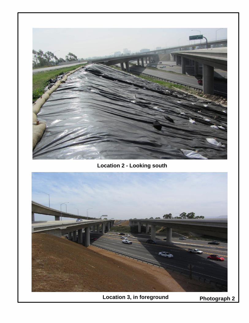
Photograph 2
Location 2 - Looking south
Location 3, in foreground

ATTACHMENT C:
RISK REGISTER

LEVEL 2 - RISK REGISTER Project Name: DIST- EA 12-0P090_Project
Manager
Status ID # Type Category Title Risk Statement Current status/assumptions Probability Cost Impact Cost Score Time Impact Time Score Rationale Strategy Response Actions Risk Owner Updated
Active12-0P090-
0-1Threat Design Electrical
TCA-owned fiber optics may be damaged during construction, Due to not having the detailed as built, in result additional cost may be needed
It has been assumed that fiber optics are outside work area
3-Moderate 8 -High 24 4 -Moderate 12 AvoidProtect in Place; Place strong language in SSP.
Shahram Shahriari, Branch Chief, Electrical
Engineering
Active12-0P090-
0-2Threat Construction Cultural/Paleo
Due to finding cultural resources in the vicinity, cultural resources may be found resulting in additional time and cost. Potential fossils during construction
During PA&ED, there will be borings that may confirm presence of cultural resources. It is still a construction risk.
3-Moderate 2 -Low 6 2 -Low 6 AcceptConstruction will be halted for expert consultation.
Cheryl Sinopoli, Environmental
Specialist, Environmental
Analysis
Active12-0P090-
0-3Threat Environmental Biological
Migrating nesting birds, protected under the Migratory Bird Treaty Act, may delayconstruction.
It will be determined during PA&ED phase. They may still be present during construction
2-Low 1 -Very Low 2 1 -Very Low 2 AvoidRemove vegetation outside of nesting season. During PA&ED the biologist will confirm the presence of nesting birds.
Chuck Baker, Branch Chief, Environmental
Analysis
Active12-0P090-
0-4Threat ROW
Groundwater drainage may require City easement
Dewatering of groundwater may need city easement
It will be determined by Geotechnical Design Report at PA&ED
2-Low 4 -Moderate 8 4 -Moderate 8 Accept Obtain easement.
Evangelina Washington, Branch Chief, Right-of-Way
Project Coordination
Active12-0P090-
0-5Threat Design Construction Access
Depending on level of slope repair work, construction access may require removal of the MBGR at toe of slope at Locations 2 and 3, triggering replacement of entire stretch of MBGR (~1900 feet at Location 2, ~600 feet at Location 3) with new standard guardrail
It will be determined by Geotechnical Design Report at PA&ED
3-Moderate 16 - Very High 48 4 -Moderate 12 AvoidProtect in Place; Place strong language in SSP.
Design Senior
Active12-0P090-
0-6Threat Design Excavation
Depth of excavation may be deeper than 10 feet
It will be determined by Geotechnical Design Report at PA&ED
3-Moderate 8 -High 24 4 -Moderate 12 AcceptProject will be funded for proposed excavation depth.
Design Senior
Risk AssessmentRisk Identification
12-0P090- Storm Water Mitigation Eric Dickson
Risk Response
Level 2 Risk Register

ATTACHMENT D:
STORM WATER DATA REPORT (SWDR) COVER SHEET


ATTACHMENT E:
PROJECT PRELIMINARY COST ESTIMATE

12-ORA-5PM 10.1/10.6 and PM 23.2/23.7EA - 0P090K
PROJECT DESCRIPTION:
Project Location: State Route 5 between PM 10.1 and 23.7 in the Cities of San Juan Capistrano & IrvineProposed: Propose to implement measures to prevent sediment contribution to Trabuco Creek,Marshburn Channel, and Bee Canyon Channel from slopes located on shoulder slopes on I-5 in theCities of San Juan Capistrano and Irvine, in Orange County
ROADWAY ITEMS $2,729,000
STRUCTURE ITEMS $0
SUBTOTAL CONSTRUCTION $2,729,000
RIGHT OF WAY (Current Value) $0
TOTAL PROJECT COST $2,729,000
PROJECT PRELIMINARY COST ESTIMATE, ALTERNATIVE 1
Attachment E Project Preliminary Cost Estimate.xlsx Page 1 of 5

ALTERNATIVE 2,
I. ROADWAY ITEMS
SECTION 1 Earthwork
Item No Earthwork Quantity Unit Unit Price Item Cost Section Cost
Clearing and Grubbing 1 LS 100,000$ $100,000Roadway Excavation 12,000 CY 25$ $300,000Imported Borrow (CY) 4,800 CY 40$ $192,000Geosynthetic Reinforcement 5,000 SQYD 10$ 50,000$
Total Earthwork $642,000
SECTION 2 Structural SectionTotal Structural Items $0
SECTION 3 Drainage
Item No Drainage Quantity Unit Unit Price Item Cost Section Cost
Drainage System 1 LS 106,500$ $106,500
Total Drainage $106,500
SECTION 4 Specialty Items
Item No Specialty Quantity Unit Unit Price Item Cost Section Cost
RE Office 1 LS 100,000$ 100,000$ Progress Schedule (Critical Path Method) 1 LS 20,000$ 20,000$ Hazardous Waste (ADL) 1 LS 30,000$ 30,000$ Environmental monitoring bio/cultural/paleo/sec 4f 1 LS 68,000$ 68,000$ Irrigation removal/replacement 1 LS 100,000$ 100,000$ Landscaping 1 LS 200,000$ 200,000$ Slope Paving 1 LS $10,000 10,000$
Attachment E Project Preliminary Cost Estimate.xlsx Page 2 of 5

Prepare Storm Water Pollution Prevention Plan 1 LS 10,000$ 10,000$ Job Site Management 1 LS 100,000$ 100,000$ Storm Water Annual Report 2 EA 2,000$ 4,000$ Rain Event Action Plan (REAP) 48 EA 500$ 24,000$ Storm Water Sampling and Analysis Day 20 EA 1,125$ 22,500$ CGP Fee 1 LS 2,000.00$ 2,000$ Relocate Electrical Cabinet 1 LS 30,000.00$ 30,000$
Total Specialy Items 720,500$
SECTION 5 Traffic ItemsSection Cost
Item No Traffic Quantity Unit Unit Price Item Cost
CHP/COZEEP 1 LS 20,000$ 20,000$ Construction Area Signs 1 LS 30,000$ 30,000$ Temporary Railing (Type K) 2,211 LF 30$ 66,330$ Temporary Crash Cushion Module 42 EA 300$ 12,600$ Temporary Traffic Screen 1,882 LF 3$ 5,646$ Remove Metal Beam Guard Railing 700 LF 8$ 5,787$ Reset Roadside Sign (One Post) 1 EA 215$ 215$ Midwest Guardrail System 700 LF 30$ 21,000$ End Cap 1 EA 300$ 300$ Traffic Control Systems 1 LS 30,000$ 30,000$ Traffic Management Plan - Public Information 1 LS 50,000$ 50,000$
Total Traffic Items 241,878$
SUBTOTAL SECTIONS 1 to 5 $1,710,878
Attachment E Project Preliminary Cost Estimate.xlsx Page 3 of 5

SECTION 6 Minor Item
Subtotal Sections 1 to 5 $1,710,878 x 10% = $171,088
Total Minor Items $171,088
SECTION 7 Roadway Mobilization
Subtotal Sections 1 to 6 $1,881,966 x 10% = $188,197
Total Roadway Mobilization $188,197
SECTION 8 Roadway Additions
Supplemental
Subtotal Sections 1 to 6 $1,881,966 x 10% = $188,197
Contingencies
Subtotal Sections 1 to 6 $1,881,966 x 25% = $470,492
Total Roadway Additions $658,688
TOTAL ROADWAY ITEMS $2,729,000
(Sections 1 to 8)
Attachment E Project Preliminary Cost Estimate.xlsx Page 4 of 5

II. STRUCTURE ITEMS
STRUCTURES ITEMS STRUCTURETOTAL STRUCTURES ITEMS $0
III. RIGHT OF WAYTOTAL RIGHT OF WAY (ITEMS)** $0
Attachment E Project Preliminary Cost Estimate.xlsx Page 5 of 5