12 amp 20” electric snow thrower 8122 - mantis … 12 amp 20” electric snow thrower operator’s...
TRANSCRIPT

OPERATOR / PARTS MANUAL12 Amp 20” Electric Snow Thrower8122

2 12 Amp 20” Electric Snow Thrower Operator’s Manual Contact us at www.mantis.com • (800) 366-6268 3
CALIFORNIA Proposition 65 Warning
Battery post, terminals, wiring insulation, and related accessories contain lead and lead
compounds, chemicals known to the State of California to cause cancer, birth defects and other
reproductive harm. WASH HANDS AFTER HANDLING.
IMPORTANT MESSAGE
Thank you for purchasing this Mantis product. You have purchased a world class product, one of the best designed and built anywhere.
This machine comes with an Operator / Parts Manual. The useful life and good service you receive from this machine depends to a large extent on how well you read and understand this manual. Treat your machine properly, lubricate and adjust it as instructed, and it will give you many years of reliable service.
Your safe use of this Mantis product is one of our prime design objectives. Many safety features are built in, but we also rely on your good sense and care to achieve accident-free operation. For best protection, study the manuals thoroughly. Learn the proper operation of all controls. Observe all safety precautions. Follow all instructions and warnings completely. Do not remove or defeat any safety features. Make sure those who operate this machine are as well informed and careful in its use as you are.
Mantis designs and builds its equipment to serve many years in a safe and productive manner. For longest life, use this machine only as directed in the manuals, keep it in good repair and follow safety warnings and instructions. You’ll always be glad you did.
Schiller Grounds Care, Inc.1028 Street Road
Southampton, PA 18966 U.S.A.PHONE 215-357-5110 • FAX 215-357-8045
PAGESAFETY RULES & WARNINGS ...................................................................................................................4-6ASSEMBLY .................................................................................................................................................7-10ELECTRICAL ................................................................................................................................................ 11OPERATION .............................................................................................................................................12-13MAINTENANCE ........................................................................................................................................14-15STORAGE ......................................................................................................................................................16PARTS SECTION ......................................................................................................................................17-18TROUBLESHOOTING ...................................................................................................................................19LIMITED WARRANTY ....................................................................................................................................20
This Operator / Parts Manual is part of the machine. Suppliers of both new and second-hand machines must make sure that this manual is provided with the machine.
TABLE OF CONTENTS
WARNING

You will notice throughout this Owners Manual Safety Rules and Important Notes. Make sure you understand and obey these warnings for your own protection.I. SPEcIAL SAfETy INfORMATION
II. SAFETy & WARNINGS
III. SAFETy DECAL INFORmATIONAn important part of the safety system incorporated in this snow thrower are the warning and information decals found on various parts of the snow thrower. These decals must be replaced in time due to abrasion, etc. It is your responsibility to replace these decals when they become hard to read.
Iv. SAfETy RULES This machine is NOT intended for use by persons (including children) with reduced physical, sensory or mental capabilities, or lack of experience and knowledge, unless they have been given supervision or instruction concerning use of the machine by a person responsible for their safety.Children should be supervised to ensure that they do not play with the machine.
TRAINING1. Read the operating and service instruction manual
carefully. Be thoroughly familiar with the controls and the proper use of the equipment. Know to stop the unit and disengage the controls quickly.
2. Never allow children to operate the equipment. Never allow adults to operate the equipment without proper instruction.
3. Keep the area of operation clear of all persons, particularly small children, and pets.
4. Exercise caution to avoid slipping or falling, especially during operation.
PREPARATION1. Thoroughly inspect the area where the equipment is to
be used and remove all doormats, sleds, boards, wires, and other foreign objects.
2. Do not operate the equipment without wearing adequate winter garments. Wear footwear, which will improve footing on slippery surfaces.
OPERATION1. Do not put hands or feet near or under rotating parts.
Keep clear of the discharge opening at all times.2. Exercise extreme caution when operating on or
crossing gravel drives, walks, or roads. Stay alert for hidden hazards or traffic.
3. After striking a foreign object, stop the motor, disconnect the power supply, thoroughly inspect the snow thrower for any damage, and repair the damage before restarting and operating the snow thrower.
4. If the unit should start to vibrate abnormally, stop the motor, disconnect the power supply and check immediately for the cause. Vibration is generally a warning of trouble.
5. Stop the motor and disconnect the power supply, before unclogging the collector/impeller housing or discharge guide, and when making any repairs, adjustments, or inspections.
6. When cleaning, repairing, or inspecting, make certain the collector/impeller and all moving parts have stopped.
7. Do not clear snow across the face of slopes. Exercise extreme caution when changing direction on slopes. Do not attempt to clear steep slopes.
Safety Rules & WarningsSafety Rules & Warnings
4 12 Amp 20” Electric Snow Thrower Operator’s manual
Attention: This symbol points out our important safety instructions. When you see this symbol ,
heed it’s warning !! Stay alert !!
Improper use or care of this machine or failure to wear proper protection can result in serious injury. Read and understand the rules for safeoperation and all instructions in this manual.
Wear hearing and eye protection.
To reduce the potential for accidents, comply with the safety instructions in this manual. Failure to
comply may result in serious personal injury, and/or equipment and property damage.
8. Never operate the snow thrower without proper guards, plates or other safety protective devices in place.
9. Never operate the snow thrower near glass enclosures, automobiles, window wells, etc. without proper adjustment of the snow discharge angle. Keep children and pets away.
10. Do not overload the machine capacity by attempting to clear snow at too fast a rate.
11. Never direct discharge at bystanders or allow anyone in front of the unit.
12. Disconnect the power supply when the snow thrower is transported or not in use.
13. Use only attachments and accessories approved by the manufacturer of the snow thrower.
14. Never operate the snow thrower without good visibility or light. Always be sure of your footing, and keep a firm hold on the handles. Walk; never run.
mAINTENANCE AND STORAGE1. Check the unit at frequent intervals to be sure the
equipment is in safe working condition.2. Always refer to owner’s guide instructions for important
details if the snow thrower is to be stored for an extended period.
3. Maintain or replace safety and instructions labels, as necessary.
4. Run the machine a few minutes after throwing snow to prevent freeze-up of the collector/impeller.
5. General maintenance written instructions shall be provided with the equipment for maintenance operations recommended by the manufacturer to maintain the equipment in safe operating condition.
SERvIcEServicing requires extreme care and knowledge and should be performed only by a qualified service technician. For service please contact Mantis. A Mantis representative can direct you to an AUTHORIZED SERVICE CENTER for repair or provide the appropriate direction to best address your servicing issue. When servicing, use only identical replacement parts.If the supply cord is damaged, it must replaced by the manufacturer, its service agent or similarly qualified persons in order to avoid a hazard.
WARNING
WARNING
WARNING
Contact us at www.mantis.com • (800) 366-6268 5
Precautions that involve your safety.
Read Operator/Parts Manual before using snow shovel, or performing any repair or maintenance. Keep owner’s manual in a safe place.
Wear eye protection when operating this machine.
Pay attention that bystanders are not injured through foreign objects thrown from the snow shovel.
Keep hands away from the collector/impeller.
Keep all bystanders (especially children and pets) at least 100 ft. away from the work area.
Do not operate on inclines greater than 15°.
Danger - Keep feet away from the collector/impeller.
Keep hands and feet away from rotating parts.
Do not expose to rain or use in damp locations.
The power supply must be disconnected before carrying out cleaning or maintenance. Shut off the motor before unclogging the discharge shute.

DESCRIPTION (Figure 1)1. Upper handle2. Middle handle3. Lower handle4. Wheel5. Cover screws6. Belt cover
This product requires assembly.• Carefully remove the product and any accessories from the box. Make sure that all items listed in the packing list are included.
• Inspect the product carefully to make sure no breakage or damage occurred during shipping.
• Do not discard the packing material until you have carefully inspected and satisfactorily operated the product.
• If any parts are damaged or missing, please contact Mantis for assistance.
PACKING LIST• Snow thrower • Discharge directional control
AssemblySafety Rules & Warnings
6 12 Amp 20” Electric Snow Thrower Operator’s manual
To avoid serious personal injury, do not attempt to use this product until you have read this
Owner’s manual thoroughly and understand it completely.
Do not use this product if any parts on thepacking list are already assembled to your product when you unpack it. Parts on this
list are not assembled to the product by the manufacturer and require customer installation. Use of a product that may have been improperly
assembled could result in serious personal injury.
If any parts are damaged or missing, do notoperate this product until the parts are replaced.
Failure to heed this warning could result in serious personal injury.
Do not connect to power supply until assembly is complete. Failure to comply could result in accidental
starting and possible serious personal injury.
Do not allow familiarity with this product to make you careless. Remember that a careless fraction of
a second is sufficient to inflict serious injury.
Do not attempt to modify this product or create accessories not recommended for use with this product. Any such alteration or modification is
misuse, and could result in a hazardous condition leading to possible serious personal injury.
The operation of any power tool can result in foreign objects being thrown into your eyes, which can result in severe eye
damage. Before beginning power tool operation, always wear safety goggles or safety glasses with side shields and, when needed, a full face shield. We recommend Wide Vision Safety mask for use over eyeglasses or standard safety glasses with side shields. Always use eye protection which is
marked to comply with ANSI Z87.1.
2
1
3
4
5
678
9
10
11
12
FIGURE 1
WARNING WARNING
WARNING
WARNINGWARNING
WARNING WARNING
7. Scraper8. Impeller9. Discharge chute10. Chute deflector11. Discharge directional control12. Switch box
• Chute deflector• Owner's Manual
Contact us at www.mantis.com • (800) 366-6268 7

ASSEmBLING THE DISCHARGE CHUTE (Figure 4) • Position the chute deflector (1) over the discharge chute (2), and align the mounting holes.
• Insert a rubber washer (5) between the chute deflector (1) and the discharge chute, maintaining the alignment of the holes (3).
• Attach the chute deflector to the discharge chute using a carriage bolt (4), 2 washers (5), and a locknut (6).
• Insert a rubber washer (8) between the chute deflector (1) and the discharge chute, maintaining the alignment of the holes (10).
ASSEmBLING THE HANDLE (Figure 2)• Remove any packing material that may have been inserted between the upper and lower handles for shipping purposes.
• Align the holes on the upper handle with the holes on the middle handle. Insert the bolts, and use the wing nuts to tighten them.
• Align the holes on the middle handle and the lower handle. Insert the bolts, and tighten them using the wing nuts provided.
USING THE CORD RETAINER (Figure 3)• Attach the outlet end of an extension cord to the plug on the rear of the snow thrower.
• Make a loop in the extension cord. From the right side, pass the loop through the hole in the back of cord retainer and place it around the hook.
AssemblyAssembly
8 12 Amp 20” Electric Snow Thrower Operator’s Manual
make sure not to pinch the power cord ; makecertain all nuts and bolts are tightened securely.
FIGURE 2
FIGURE 4
FIGURE 3
NOTE: Do not plug the extension cord into the outlet until it has been connected to the cord retainer and plugged into the snow thrower.
WARNING
Bolt
Bolt
Wing nut
Wing nut
Plug
Cord Retainer
1
2
3
4
55
6
789
10
11
NOTE: Do not overtighten the bolts.
NOTE: The rubber washers, bolts and locknuts are all pre-installed to the chute deflector. Remove them before installing the chute deflector.
Contact us at www.mantis.com • (800) 366-6268 9
• Attach the chute deflector to the discharge chute using 2 carriage bolts (7), 4 washers (8), 4 external teeth serrated lock washers (11) and 2 locknuts (9).
10 12 Amp 20” Electric Snow Thrower Operator’s Manual
ElectricalAssembly
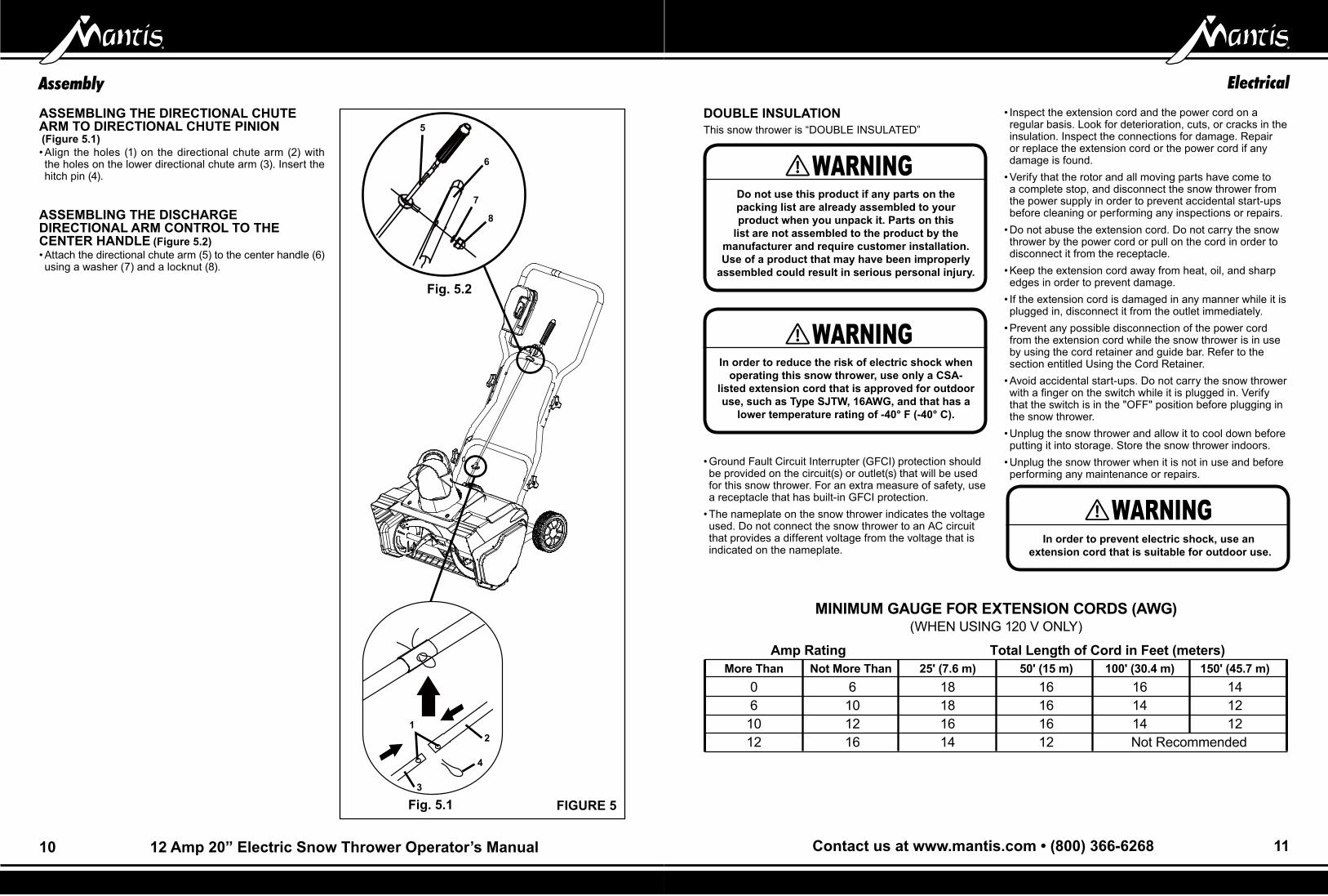
DOUBLE INSULATION This snow thrower is “DOUBLE INSULATED”
• Ground Fault Circuit Interrupter (GFCI) protection should be provided on the circuit(s) or outlet(s) that will be used for this snow thrower. For an extra measure of safety, use a receptacle that has built-in GFCI protection.
• The nameplate on the snow thrower indicates the voltage used. Do not connect the snow thrower to an AC circuit that provides a different voltage from the voltage that is indicated on the nameplate.
Do not use this product if any parts on thepacking list are already assembled to your product when you unpack it. Parts on this
list are not assembled to the product by the manufacturer and require customer installation. Use of a product that may have been improperly
assembled could result in serious personal injury.
In order to prevent electric shock, use an extension cord that is suitable for outdoor use.
In order to reduce the risk of electric shock when operating this snow thrower, use only a CSA-
listed extension cord that is approved for outdoor use, such as Type SJTW, 16AWG, and that has a
lower temperature rating of -40° F (-40° C).
• Inspect the extension cord and the power cord on a regular basis. Look for deterioration, cuts, or cracks in the insulation. Inspect the connections for damage. Repair or replace the extension cord or the power cord if any damage is found.
• Verify that the rotor and all moving parts have come to a complete stop, and disconnect the snow thrower from the power supply in order to prevent accidental start-ups before cleaning or performing any inspections or repairs.
• Do not abuse the extension cord. Do not carry the snow thrower by the power cord or pull on the cord in order to disconnect it from the receptacle.
• Keep the extension cord away from heat, oil, and sharp edges in order to prevent damage.
• If the extension cord is damaged in any manner while it is plugged in, disconnect it from the outlet immediately.
• Prevent any possible disconnection of the power cord from the extension cord while the snow thrower is in use by using the cord retainer and guide bar. Refer to the section entitled Using the Cord Retainer.
• Avoid accidental start-ups. Do not carry the snow thrower with a finger on the switch while it is plugged in. Verify that the switch is in the "OFF" position before plugging in the snow thrower.
• Unplug the snow thrower and allow it to cool down before putting it into storage. Store the snow thrower indoors.
• Unplug the snow thrower when it is not in use and before performing any maintenance or repairs.
mINImUm GAUGE FOR EXTENSION CORDS (AWG) (WHEN USING 120 V ONLY)
Amp Rating Total Length of Cord in Feet (meters) more Than Not more Than 25' (7.6 m) 50' (15 m) 100' (30.4 m) 150' (45.7 m) 0 6 18 16 16 14 6 10 18 16 14 12 10 12 16 16 14 12 12 16 14 12 Not Recommended
WARNING
WARNING
WARNING
ASSEmBLING THE DIRECTIONAL CHUTE ARm TO DIRECTIONAL CHUTE PINION (Figure 5.1)• Align the holes (1) on the directional chute arm (2) with the holes on the lower directional chute arm (3). Insert the hitch pin (4).
ASSEmBLING THE DISCHARGE DIRECTIONAL ARm CONTROL TO THE CENTER HANDLE (Figure 5.2)• Attach the directional chute arm (5) to the center handle (6) using a washer (7) and a locknut (8).
FIGURE 5Fig. 5.1
Fig. 5.2
12
5
6
7
8
3
4
Contact us at www.mantis.com • (800) 366-6268 11

STARTING THE SNOW THROWER (Figure 6)• Rotate the lever release counterclockwise and hold to allow access to the switch control lever.
• Pull the switch control lever toward the snow thrower handle and let go of the lever release. Continue to hold the switch control lever against the snow thrower handle in order to keep it running.
• To stop the snow thrower, release the switch control lever.
ADJUSTING THE DIRECTION OF DISCHARGESnow can be discharged to the left, straight ahead, or to the right of the operator.Follow these instructions in order to change the direction:• Release the safety switch in order to stop the rotor.
• Turn the discharge directional control clockwise 360°. The vanes will turn approximately 80° to the right.
• Turn the discharge directional control counter-clockwise 360°. The vanes will turn approximately 80° to the left.
OperationOperation
12 12 Amp 20” Electric Snow Thrower Operator’s Manual
In order to avoid serious personal injury, turn the snow thrower off and unplug it before cleaning or
servicing.
Avoid accidental start-ups. Verify that the operator is in the starting position when using
the snow thrower. In order to avoid serious injury, the operator and unit must be in a stable position
when starting the snow thrower.
If the snow thrower hits a foreign object while it is in use, the object could be thrown in the direction
of the operator or a bystander. Thrown objects could cause serious personal injury. Keep area cleared free of all foreign objects that may be
picked up and thrown by the rotor blades.
If there is a gap between the discharge chute and the chute deflector, snow and anything else that can be picked up by snow thrower may fly in the direction of the operator. Thrown objects could
cause serious personal injury.
Do no attempt to override the operation of this safety switch. FIGURE 6
FIGURE 7
NOTE: A high-pitched noise and sparking may occur as the electric motor decelerates. This is normal.
NOTE: The chute crank makes a noise as it is turned. This is normal.The deflector handle that is located on the top of the discharge chute controls the height of the snow stream (Fig. 7).Adjust the height of the snow stream by raising or lowering the chute deflector.
NOTE: The control crank can revolve 810°. The discharge chute can rotate 180°. Do not force it.
WARNING
WARNING
WARNING
CAUTION
WARNING
OPERATING TIPS• Keep children and pets away from the operating area.• Keep area cleared free of stones, toys, or other foreign objects that the rotor blades can throw. Such items may be covered by a snowfall and go unnoticed. If the snow thrower strikes an obstruction or a foreign object during operation, stop the snow thrower, unplug the extension cord, remove the obstruction, and inspect the snow thrower for damage.
• Rotate the chute crank clockwise in order to move the discharge chute to the left, or rotate it counter-clockwise in order to move the chute to the right.
• Do not force the chute deflector too far forward so that a gap appears between the discharge chute and the chute deflector.
• Do not overtighten the locknuts that hold the chute deflector in position to the point where it is necessary to use excessive force in order to adjust the chute deflector.
• Begin removing snow near the electrical outlet, and work outward. Work back and forth, and not away from or toward the outlet.
• When turning at the end of a swath, step over the cord, and then turn the snow thrower.
• Overlap each swath, and discharge the snow in the direction of the wind whenever possible.
• Shave down large banks of snow by placing the snow thrower on the bank. Allow the weight of the snow thrower to shave down the bank in a back-and-forth motion.
• Keep the extension cord clear of obstructions, sharp objects, and all moving parts. Do not pull sharply on the cord or abuse it in any manner. Inspect the extension cord for damage that may result in an electric shock on a regular basis. If the extension cord becomes damaged in any way, replace it immediately.
• Some controls and moving parts may freeze in certain cold and snowy weather conditions. If any of the controls become hard to operate, stop the motor, disconnect the extension cord, and inspect the snow thrower for frozen parts.
• Do not use excessive force when trying to operate frozen controls. Free all of the controls and moving parts before using the snow thrower.
• When operating the snow thrower, keep the wheels 1" (2.5 cm) off the pavement by tipping the Snow Thrower forward. This will help to prevent the snow from building up on the wheels.
• After clearing the snow, allow the motor run for a few minutes so that the ice doesn’t freeze any moving parts. Then shut off the motor, wait for all moving parts to come to a complete stop, and wipe the ice and snow off the snow thrower. Rotate the chute crank several times in order to remove the snow from the snow thrower.
• Lock the snow thrower when it is not in use. Disconnect the extension cord.
Lever Release
SwitchControl Lever
SwitchControl Lever
Deflector handle
Contact us at www.mantis.com • (800) 366-6268 13

REPLACING THE SCRAPER (Figure 8)The scraper is located at the bottom of the rotor housing.• Remove the 5 screws that secure the scraper to the snow thrower.
• Install the new scraper, and attach it securely using the 5 screws.
REPLACING THE DRIVE BELT (Figure 9-10)• Remove the 4 screws that secure the left side plate to the frame of the snow thrower (Fig. 9). Remove the side plate.
• Pull the bearing away from the small pulley. Remove the belt from the large pulley and the small pulley that is located inside the housing (Fig. 9).
• Position the new belt over the small pulley (Fig. 10).• Rotate the rotor with the left hand while positioning the belt on the large pulley with the right hand (Fig. 10).
• Install the left side cover, and secure it using the 4 screws.
REPLACING THE ROTOR (Figure 11-14)• Remove the 4 screws that secure the right side cover to the frame of the Snow Thrower (Fig. 11).
• Remove the short shaft (Fig. 12).• Push the sides of the housing out, as illustrated in Figure 13 and remove the rotor (Fig. 14).
• Install the new rotor, and reinstall the clip.• Reinstall the right side cover, and secure it using the 4 screws.
MaintenanceMaintenance
14 12 Amp 20” Electric Snow Thrower Operator’s manual
FIGURE 8
FIGURE 11
FIGURE 12
FIGURE 13
FIGURE 14
FIGURE 9
FIGURE 10
Screw Right side coverScrew
Bearing
Left side cover
Large pulleySmallpulleyBeltScrew
Bearing
Large pulley
Smallpulley
Belt
Short shaft
Contact us at www.mantis.com • (800) 366-6268 15

Parts sectionStorage
16 12 Amp 20” Electric Snow Thrower Operator’s manual
• Run the snow thrower for a few minutes in order to melt any snow that may be left on the snow thrower.
• Disconnect the extension cord from the snow thrower.• Inspect the extension cord thoroughly for signs of wear or damage. Replace it if it is worn or damaged.
• Inspect the snow thrower thoroughly for worn, loose, or damaged parts.
• Store the extension cord with the snow thrower.• Store the snow thrower in a clean, dry place. Cover it in order to provide added protection.
Contact us at www.mantis.com • (800) 366-6268 17

TroubleshootingParts section
18 12 Amp 20” Electric Snow Thrower Operator’s Manual
PROBLEM POSSIBLE cAUSE SOLUTION Then handle is not in The carriage bolts are not properly Adjust the height of the handle, and verify that the position. seated. carriage bolts are properly seated. Tighten the knobs.
The snow thrower does The power cord is disconnected from Reconnect the cord, and use the cord restraint to not start. the switch. keep the cord close to the switch. The switch is defective. Replace the switch. The extension cord is not connected to Connect the plug on the snow thrower to the the plug. extension cord. The extension cord is not connected to Plug the extension cord into a live 120 V AC, 60 Hz the power source. outlet.
The motor is on, but the The belt is damaged. Replace the belt (see the section entitled rotor does not turn. Inspecting/Replacing the Drive Belt).
The Snow Thrower The scraper is worn. Replace the scraper (see the section leaves a thin layer of entitled Replacing the Scraper). snow behind.
ITEm NO. PART NO. DESCRIPTION
1 33306100 Left side board
2 3290198 Belt
3 34901100 Synchronous belt
4 33212100 Tensioner fix shaft
5 32104100 Tensioner bearing
6 33211100 Tensioner shaft
7 33903100 Tensioner spring
8 34165100 Motor vent cover
9 32201100 Locknut
10 33305100 Tensioner bracket
11 3290699 Washer
12 32203100 Cross screw
13 33301100-2 Motor support
14 31120100-1 Motor assembly
15 3220505 Screw
16 34120100-1 Waterproof bracket
17 33378100 Motor clamp
18 32208100 Cross screw
19 32210100 Washer
20 322011213 Nylock nut M3.5
21 3410835-59 Knob
22 32215100 Washer
23 34111100-1 Chute deflector
24 32216100 Hex screw
25 34110100-2 Discharge chute
26 32207100 Cross screw
27 34104100-2 Out chute cover
28 34121100A Waterproof support
29 34106100-1 Inlet chute cover
30 33307100 Right side board
31 34102100-9 Rear cover
32 34160100 Pinion bracket
33 34161100 Plate
34 34162100 Square bushing
35 33260100 Pin
36 32288100 Screw
37 32901261 Locknut
38 31107100-1 Pigtail cable
39 311021212 Switch assembly
40 33207100-13 Middle handle
41 3290299 Washer
42 3330499 Screw
QTy
1
1
1
1
1
1
1
2
7
1
7
4
1
1
9
1
1
1
2
1
2
4
1
2
1
20
1
2
1
1
1
1
1
1
1
1
1
1
1
1
2
1
QTy
1
1
1
1
1
1
1
1
1
1
4
4
2
2
2
1
1
2
1
2
1
12
2
1
4
1
1
1
1
2
3
1
1
1
1
1
ITEm NO. PART NO. DESCRIPTION
43 3420199 Rubber
44 3410499A-9 Handle
45 33306699 Washer
46 32901251 Retaining ring
47 33208628-9 Upper handle
48 3490137-1 Soft grip sponge
49 3290599 Nut
50 33214100-3 Rear rocker
51 3320643 Hitch pin
52 33214100-2 Upper rocker
53 3220436 Bolt
54 3410835-4 Knob
55 3290135 Split pin
56 3411799C-12 Wheel cover
57 3220898 Washer
58 3411799-22 6” Wheel (right)
59 33206100-13 Lower handle
60 34250100 Rubber sleeve
61 3411799-12 6” Wheel (left)
62 33304100 Front support
63 33201100A Short shaft
64 32206100 Cross screw
65 32102100 Waterproof bearing
66 33309100 Right support
67 34158100 Inner cord clamp
68 34105100-1 Vane
69 31118100 Impellor assembly
70 34101100-9 Front cover
71 33308100 Left support
72 3220651 Nut
73 32217100 Washer
74 33203100A Pulley wheel support shaft
75 31110100A Pulley wheel assembly
76 34109100-1 Driver wheel
77 33273100 Left barrier chip
78 33274100 Right barrier chip
Contact us at www.mantis.com • (800) 366-6268 19

LIMITED WARRANTY
MANTIS extends this limited warranty against defects in material and workmanship for a period of two (2) years under normal usage for residential purposes from the date of purchase by the original purchaser.MANTIS will repair or replace, at its discretion, any part or parts of the product found to be defective in material or workmanship during the warranty period. Warranty repairs and replacements will be made without charge for parts or labor. All parts replaced under warranty will be considered as part of the original product, and any warranty on the replaced parts will expire coincident with the original product warranty. If you think your MANTIS ELECTRIC SNOW THROWER is defective in material or workmanship contact Mantis and you will be instructed to send it, along with your proof of purchase (sales receipt) to:
Mantis1028 Street RoadSouthampton, PA 18966
You are responsible for pickup and delivery charges; the product must be returned to us postage paid.MANTIS assumes no responsibility in the event that the product was not assembled or used in compliance with any assembly, care, safety, or operating instructions contained in the Owner’s Manual or accompanying the product. This limited warranty does not cover damages or defects due to normal wear and tear, lack of reasonable and proper maintenance, failure to follow operating instructions or owner’s manual, misuse, lack of proper storage or accidents [or routine maintenance parts and service]. This limited warranty shall not be effective if your Mantis electric snow thrower has been subjected to negligence or has been repaired or altered by anyone other than Mantis or Mantis authorized dealer or authorized service center.
You must maintain your MANTIS ELECTRIC SNOW THROWER by following the maintenance proce-dures described in the owner’s manual. Such routine maintenance, whether performed by you or a dealer, is at your expense.
MANTIS MAKES NO EXPRESS OR IMPLIED WARRANTIES, REPRESENTATIONS OR PROMISES EXCEPT THOSE CONTAINED HEREIN. THERE ARE NO OTHER WARRANTIES, INCLUDING WARRANTIES OF MERCHANTABILITY AND FITNESS FOR A PARTICULAR PURPOSE. ALL WARRANTIES OTHER THAN THE EXPRESS WARRANTY SET FORTH ABOVE ARE SPECIFICALLY DISCLAIMED. THE DURATION OF ANY IMPLIED WARRANTY, INCLUDING MERCHANTABILITY AND FITNESS FOR A PARTICULAR PURPOSE, IS LIMITED TO THE DURATION OF THIS WRITTEN LIMITED WARRANTY. MANTIS DISCLAIMS ALL LIABILITY FOR INDIRECT, INCIDENTAL AND/OR CONSEQUENTIAL DAMAGES IN CONNECTION WITH THE USE OF THE MANTIS PRODUCTS COVERED BY THIS WARRANTY. SOME STATES DO NOT ALLOW LIMITATIONS ON HOW LONG AN IMPLIED WARRANTY LASTS AND/OR DO NOT ALLOW THE EXCLUSION OR LIMITATION OF INCIDENTAL OR CONSEQUENTIAL DAMAGES, SO THAT ABOVE LIMITATIONS AND EXCLUSIONS MAY NOT APPLY TO YOU. THIS WARRANTY GIVES YOU SPECIFIC LEGAL RIGHTS, AND YOU MAY ALSO HAVE OTHER RIGHTS WHICH VARY FROM STATES TO STATE.
MANTIS1028 Street RoadSouthampton, PA 18966800-366-6268
© 2014 Schiller Grounds Care, Inc. All Rights Reserved, P/N 430102