11.10 horn-loudspeakers - gitec forum
TRANSCRIPT
11.10 Horn-loudspeakers
© M. Zollner 2008 – 2014 Translated by Tilmann Zwicker
11-91
11.10 Horn-loudspeakers
The classic guitar speaker arrangement does not feature a horn – but in a PA, or in the control-room of a recording studio, horn-loudspeakers may well be deployed. This is to increase the scarily low efficiency, and to modify the directionality. In a studio-speaker at most only about 3% of the power generated by the amplifier is converted to sound (Chapter 11.5), so experiments to improve the matching were done early on [Olsen]. The source impedance of the membrane is relatively large, and that of the load is small: in such a scenario, we would call for a transformer in electrical engineering; in acoustics, we would call for – right: a horn.
, J1 = Bessel-function
, H1 = Struve’s function
, a = membrane-radius
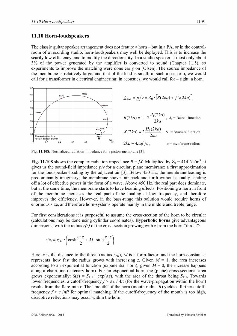
Fig. 11.108: Normalized radiation-impedance for a piston-membrane [3].
Fig. 11.108 shows the complex radiation impedance R + jX. Multiplied by Z0 = 414 Ns/m3, it gives us the sound-field impedance p/v for a circular, plane membrane: a first approximation for the loudspeaker-loading by the adjacent air [3]. Below 450 Hz, the membrane loading is predominantly imaginary; the membrane shoves air back and forth without actually sending off a lot of effective power in the form of a wave. Above 450 Hz, the real part does dominate, but at the same time, the membrane starts to have beaming effects. Positioning a horn in front of the membrane increases the real part of the loading at low frequency, and therefore improves the efficiency. However, in the bass-range this solution would require horns of enormous size, and therefore horn-systems operate mainly in the middle and treble range. For first considerations it is purposeful to assume the cross-section of the horn to be circular (calculations may be done using cylinder coordinates). Hyperbolic horns give advantageous dimensions, with the radius r(z) of the cross-section growing with z from the horn-“throat”:
Here, z is the distance to the throat (radius rTH), M is a form-factor, and the horn-constant ε represents how fast the radius grows with increasing z. Given M = 1, the area increases according to an exponential function (exponential horn); given M = 0, the increase happens along a chain-line (catenary horn). For an exponential horn, the (plane) cross-sectional area grows exponentially: S(z) = STH ⋅ exp(ε z), with the area of the throat being STH. Towards lower frequencies, a cutoff-frequency f > ε c / 4π (for the wave-propagation within the horn) results from the flare-rate ε. The “mouth” of the horn (mouth-radius R) yields a further cutoff-frequency f > c /πR for optimal matching. If the cutoff-frequency of the mouth is too high, disruptive reflections may occur within the horn.

11. Loudspeakers
Translated by Tilmann Zwicker © M. Zollner 2008 - 2014
11-92
Fig. 11.109 shows, for three different horns, the cross-section as it develops with the increasing value of z, and also the logarithm of the real part of the acoustical load impedance (0 dB = Z0); on the right, the impedance without the horn (red curve) is included for comparison. For calculating the load, the length of the horn was assumed to be infinite so that reflections and standing waves could be ruled out. In horns of finite length, part of the wave running towards the mouth is reflected; the smaller the opening at the mouth is, the stronger the reflection. Fig. 11.110 depicts two cases of identical wave-cutoff frequency but different mouth-cutoff frequency. The optimum angle at the mouth is about 90°.
Fig. 11.109: Cross section (links) and membrane-loading for various horns. Throat-radius = 5 cm.
Fig. 11.110: Logarithm of the real part of the membrane loading for two different horn lengths; equal ε .
The circular cross-sectional area is a first approach towards calculation. In reality the cross-section develops from a round throat-area to a rectangular mouth-area, allowing for different directionality in the vertical plane compared to the horizontal plane. The beam-width Φ is a measure for the radiation but still remains rather limited in its meaningfulness, as it is seen in Fig. 11.111: despite equal angle the directivity of two loudspeakers may differ significantly.
Fig. 11.111: Directionality; differing
directionality factor despite equal
aperture angle.
11.10 Horn-loudspeakers
© M. Zollner 2008 – 2014 Translated by Tilmann Zwicker
11-93
Besides the beam-width that gives a single number for the beaming behavior in one plane, the directivity yields an average value for all directions. Formally, the squared directional gain Γ
needs to be integrated in space along an enveloping surface surrounding the source, and reciprocally be referring to this surface [3]. The logarithm of the resulting beaming index γ
becomes the directivity d. In the simplest case, a sphere with the surface area of HF = 4π r2
serves as the enveloping surface.
HF = enveloping area
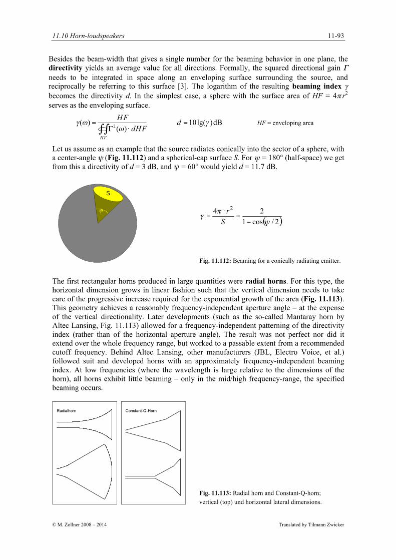
Let us assume as an example that the source radiates conically into the sector of a sphere, with a center-angle ψ (Fig. 11.112) and a spherical-cap surface S. For ψ = 180° (half-space) we get from this a directivity of d = 3 dB, and ψ = 60° would yield d = 11.7 dB.
Fig. 11.112: Beaming for a conically radiating emitter.
The first rectangular horns produced in large quantities were radial horns. For this type, the horizontal dimension grows in linear fashion such that the vertical dimension needs to take care of the progressive increase required for the exponential growth of the area (Fig. 11.113). This geometry achieves a reasonably frequency-independent aperture angle – at the expense of the vertical directionality. Later developments (such as the so-called Mantaray horn by Altec Lansing, Fig. 11.113) allowed for a frequency-independent patterning of the directivity index (rather than of the horizontal aperture angle). The result was not perfect nor did it extend over the whole frequency range, but worked to a passable extent from a recommended cutoff frequency. Behind Altec Lansing, other manufacturers (JBL, Electro Voice, et al.) followed suit and developed horns with an approximately frequency-independent beaming index. At low frequencies (where the wavelength is large relative to the dimensions of the horn), all horns exhibit little beaming – only in the mid/high frequency-range, the specified beaming occurs.
Fig. 11.113: Radial horn and Constant-Q-horn;
vertical (top) und horizontal lateral dimensions.

11. Loudspeakers
Translated by Tilmann Zwicker © M. Zollner 2008 - 2014
11-94
Fig. 11.114 shows the beaming of a radial horn [D.B. Keele, AES Prep. 1083] compared to a constant-Q-horn [JBL 2356A]. The directivity index (i.e. DI and d, respectively) increases between 500 Hz and 15 kHz by 10 dB for the radial horn. On one hand, this is helpful because the power-frequency-response of typical horn-drivers decreases from about 2 kHz up, but on the other hand it is unattractive: only the direct sound, but not the diffuse sound, profits [3].
Fig. 11.114: Aperture angle and directivity index (DI) for two different horns. The radial horn was marketed as
60°x40°-horn (according to the datasheet) – rather courageous given the vertical beaming.
In midrange- and treble-horns, the horn does not directly sit on the membrane but connects to it via a compression chamber (Fig. 11.115). Assuming a location-independent pressure, the continuity requirement (q1 = q2) yields the relationship between membrane (Index 1) and the starting point of the horn (throat, Index 2): the load impedance rises by the ratio of the areas. In practice, the compression chamber is not of cylindrical shape, though, but forms a so-called phase plug that supports avoiding path-dependent interferences. Drive and membrane combine into the driver, to which horns with varying beaming behaviors can be fitted. In order to be able to specify driver-data independently of the horn, the former is mounted to a plane wave tube (PTW) – a tube with a length up to 6 m in which the waves can travel without reflections. The input impedance of the tube is approximately real: p/v = 414 Ns/m3.
Fig. 11.115: Compression chamber. Photo: Lansing-Heritage

11.10 Horn-loudspeakers
© M. Zollner 2008 – 2014 Translated by Tilmann Zwicker
11-95
In Fig. 11.116 we see a typical frequency response of a PWT. For the measurement, the driver (JBL 2451) was mounted to a 1.5”-PWT (although in the datasheet a 1"-PWT is noted). At middle frequencies, this driver reaches an electro-acoustic efficiency of 30%. From 3 kHz, the coupling deteriorates such that at 10 kHz, only 3% remain – which is not bad either. As this driver is mounted to a radial horn, the beaming of the latter (increasing with frequency) makes for a partial compensation of the treble loss, at least for the direct sound in front of the speaker. According to the rules of simple room acoustics, the beaming has no effect on the diffuse sound. The manufacturers recommend compensating the weak treble via filters (equalizer, EQ), but that only works up to a point: a 10-dB-boost requires the 10-fold power!
Fig. 11.116: Power-frequency-response and impedance of a driver [JBL 2451] mounted to a PWT. The ordinate
specifies the SPL (in dB) obtainable with Pak = 1mW. Since the acoustical loading is real, the sound pressure can
directly be recalculated into the sound power: P = p2 ⋅ S/Z0.
Fig. 11.117 shows two further horns: with acoustical lens, and with separating strips within the horn. The extreme vertical beaming of the lens is probably not entirely unrelated to its becoming extinct. The Smith-horn is a kind of multicell-horn but includes a closed bottom and a closed lid.
Fig. 11.117: Beaming for a JBL-lens (left) and for a so-called Smith-horn (right). “vertikal” = vertical