1.1 product design - biju patnaik university of technology materials and other purchased parts....
TRANSCRIPT

PRODUCT DESIGN AND PRODUCTION TOOLING
Module-I
1.1 PRODUCT DESIGN
Definition of Design: The process of applying the various techniques and scientific principles for the purpose of defining a device, a process or a system in sufficient detail to permit its realization.
Fig 1.1: The design and manufacturing processes of a product [1]
1.2 Product Design Consideration
Design is a multifaceted process. The various considerations in a good design can be grouped into three categories: (1) design requirements, (2) life-cycle issues, and (3) regulatory and social issues.
Authors: Prof. R.K. Sahoo, Dr. P.K. Parida, Prof. Chimay Das

PRODUCT DESIGN AND PRODUCTION TOOLING
1.2.1 Design requirements
It is obvious that to be satisfactory the design must demonstrate the required performance. Performance measures both function and behaviour of the design, i.e., how well the device does what it is designed to do. i) Performance requirements can be divided into following two groups.
• Functional Performance Requirements: They address capacity measures such as forces, strength, energy, material flows, power, deflection, and efficiency of design, its accuracy, sensitivity etc.
• Complementary Performance requirements: They are concerned with the useful life of design, its robustness to factors in the service environment, its reliability, and ease, economy, and safety of maintenance. Issues such as built-in safety features, noise level in operation, all legal requirements, and design codes must be considered.
ii) Physical Requirements: These pertain to such issues as size, weight, shape, and surface finish. iii) Environmental Requirements: There are two separate aspects. The first concerns the service conditions under which the product must operate. The extremes of temperature, humidity, corrosive conditions, dirt, vibration, noise, etc., must be predicted and allowed for in the design. The second aspect of environmental requirements pertains to how the product will behave with regard to maintaining a safe and clean environment, i.e., green design. Among these issues is the disposal of the product when it reaches its useful life. iv) Aesthetic Requirements: They are concerned with how the product is perceived by a customer because of its shape, colour, surface texture, and also such factors as balance, unity, and interest. v) Manufacturing Technology: This must be intimately connected with product design. There may be restrictions on the manufacturing processes that can be used, because of either selection of material or availability of equipment within the company. vi) Cost: The final major design requirement is cost. Every design has requirements of an economic nature. These include such issues as product development cost, initial product cost, life cycle product cost, tooling cost, and return on investment. 1.2.2 Total Life Cycle The total life cycle of a part starts with the conception of a need and ends with the retirement and disposal of the product. Material Selection: Material selection is a key element in the total life cycle of a product. In selecting material for a given application, the first step is evaluation of the service conditions. Next, the properties of materials that relate most directly to the service requirements must be determined.
Authors: Prof. R.K. Sahoo, Dr. P.K. Parida, Prof. Chimay Das
PRODUCT DESIGN AND PRODUCTION TOOLING
Producibility: Material selection can not be separated from Producibility. There is an intimate connection between design and material selection and the production processes. The objective in this area is a trade-off between the opposing factors of minimum cost and maximum durability. Durability: It is concerned with the number of cycles of possible operation, i.e., the useful life of the product. Current societal issues of energy conservation, material conservation, and protection of environment result in new pressures in selection of materials and manufacturing processes. Energy costs, once nearly totally ignored in design, are now among the most prominent design considerations. Design of materials recycling is becoming more and more important consideration. 1.2.3 Regulatory and Social Issues Specifications and standards have an important influence on design practice. The standards produced by such societies as ASTM, ASME, CE and BIS represent voluntary agreement among many elements (users and producers) of industry. As such, they often represent minimum or least common denominator standards. When good design requires more than that, it may be necessary to develop company or agency standards. The code of ethics of all professional engineering societies requires the engineer to protect public health and safety. Increasingly, legislation has been passed to require government agencies to regulate many aspects of safety and health. The designer has to develop the design in such a way to prevent hazardous use of the product in an unintended but foreseeable manner. When unintended use cannot be prevented by functional design, then clear, complete, unambiguous warnings must be permanently attached to the product. In addition, the designer must be cognizant of all advertising materials, owner’s manuals, and operating instructions that relate to the product to ensure that the contents of the material are consistent with safe operating procedures and do not promise performance characteristics that are beyond the capability of the design.
An important design consideration is adequate attention to human factors engineering, which uses the sciences of biomechanics, ergonomics, and engineering psychology to assure that the design can be operated efficiently by humans. It applies physiological and anthropometric data to such design features as visual and auditory display of instruments and control systems. It is also concerned with human muscle power and response time.
1.3 PRODUCT SPECIFICATION:
The product specifications are the precise description of what the product has to do. It don’t tellhow to address the customer needs, but represent an unambiguous agreement on what the team will attempt to achieve in order to satisfy the customer needs.
Example: In contrast to the customer need that “the suspension is easy to install” the corresponding specimen might be that “the average time that to assemble the fork to the frame is less than 75 seconds”.
A specification consists of a metric and a value. As in earlier example “average time to assemble” is the metric and “less than 75 seconds” is the value of this metric. The values
Authors: Prof. R.K. Sahoo, Dr. P.K. Parida, Prof. Chimay Das

PRODUCT DESIGN AND PRODUCTION TOOLING
are of several forms along with a specific unit. Together the metric and value form a specification. The product specifications are simply a set of the individual specifications.
1.3.1 Target Specification: The target specifications are established after the customer needs have been identified, but before product concepts have been generated.
The process of establishing the target specifications contains following steps:
(i) Prepare the list of metrics (ii) Collect competitive benchmarking information (iii)Set ideal and marginally acceptable target values (iv) Reflect on the results and the process.
(i) Prepare the list of Metrics: The most useful metrics are those that reflect as directly as possible the degree to which the product satisfied the customer needs. A few guide lies should be followed when constructing the list of metrics.
• Metric should be complete: Ideally each customer need would correspond to a single metric and the value of that metric would correlate perfectly with satisfaction of that need. In practice several metrics may be necessary to completely reflect a single customer need.
• Metric should be dependent, not independent variables: Metrics specify the overall performance of a product and should there fore be the dependent variable in the design problems.
• Metrics should be practical: Metrics will be directly observable or analyzable properties of the product that can be easily evaluated.
• Some needs can’t easily be translated into quantifiable metrics: In these cases the need statement simply repeats as a metric in the specifications.
• The metrics should include the popular criteria for comparison in the marketplace.
(ii) Collect competitive benchmarking information: The benchmarking chat is conceptually very simple. For each competitive product the values of the matrices are simple entered down a column. An alternative competitive benchmarking chat can be constructed with rows corresponding to the customer needs and columns corresponds to competitive products.
(iii)Set ideal and marginally acceptable target value: In this step the available information s synthesized in order to actually set the target values for the metrics. Two types of target values are useful (a) an ideal value which is the best result could hopeful (b) a marginally acceptable value which is the value of the metric that would just barely more the product commercially viable.
There are different ways to express the values of metrics:
→ At least X: These specifications establish targets for the lower bound on a metric, but higher is still better. Example: Brake mounting stiffness.
Authors: Prof. R.K. Sahoo, Dr. P.K. Parida, Prof. Chimay Das

PRODUCT DESIGN AND PRODUCTION TOOLING
→ At most Y: These specifications establish targets for the upper bound on a metric, with smaller values being better. Example: mass of suspension system.
→ Between X and Y: These specifications establish a target of a particular value of a metric with any deviation degrading performance. Example: rake offset matrix. This type of specification is to be avoided if possible because such specifications substantially constrain the design.
→ A set of discrete value: Some metrics will have values corresponding to several discrete choices. Example: the head set diameters are 1.000 to a.125 etc.
(iv) Reflect on the result and the process: The team may require some iteration to agree on targets. Reflection after each iteration helps to ensure that the results are consistent with the goals of the project.
1.3.2 Final Specification: The target specifications are expressed as broad ranges of values, when those values are refined and made more precise are called final specification. A five stage process is proposed to refine the specification as:
(i) Develop technical models of the product: A technical model of the product is a tool for predicting the values of the metrics by a particular set of design decisions.
(ii) Develop a cost model of the product: The goal of this step of the process is to make sure that the product can be produced at the target cost.
(iii) Refine the specifications, making tradeoff where necessary: Finalizing specification can be accomplished in a group session in which feasible combination of values are determined through the use of the technical models and the cost models for employing the cost implication.
(iv) Flow down the specifications as appropriate: Establishing specifications taken in additional importance and is substantially more challenging when developing a highly complex product consisting of multiple subsystems designed by multiple development teams. In such context specifications are used to define the development objectives of each of the subsystems as well as the product as a whole. The challenge in this case is to flow down the overall specification to specifications for each sub-system.
(v) Reflects on the results and the processes:As always the final step in the method is to reflect on the out-come and the process.
1.4 ROLE OF COMPUTER IN PRODUCT DESIGN:
Authors: Prof. R.K. Sahoo, Dr. P.K. Parida, Prof. Chimay Das

PRODUCT DESIGN AND PRODUCTION TOOLING
The computer has brought about a revolution in the n entire manufacturing system which comprises product design, manufacturing and management.
1.4.1 Computer Aided Design (CAD): It can be defines as the use of computer system to assist in the creation, modification, analysis or optimization of a design.
1.4.2 Computer Aided Manufacturing: It can be defined as the use of computer system to plan, manage and control the operations of the manufacturing plant. These include following:
(a) NC part programming: control programmes are prepared for automated machine tools.
(b) Computer Aided Process Planning (CAPP): It includes listing of operation sequence required for processing a particular part.
(c) Production scheduling and material requirement planning: This is a planning tool for taking decision like when to order and how much to order for raw materials and other purchased parts.
1.4.3 Computer Integrated manufacturing (CIM): A closed loop feed-back system whose prime inputs are product requirements and product concepts and whose prime outputs are finished products. It comprises a combination software and hardware product design, production planning, production control, production equipment and production processes.
1.4.4 Role of Computer in Design process: The design related tasks which are performed by a modern CAD system can be grouped into four functional areas:
(i) Geometrical modeling (ii) Engineering analysis (iii)Design review and evaluation (iv) Automated drafting
(i) Geometrical modeling: In this the designer constructs the image of the object on the CRT screen of the interactive computer graphics systems, by inputting three types of command to the computer. (a) The 1st type command generates basic geometric elements such as points, lines
and circles. (b) The 2nd type of command is meant to accomplish translation, scaling (size, shape).
Rotation or other transformation of the elements. (c) The third type of command joins the various elements to give the desired object.
During the design process the computer converts the commands into a mathematical model, stores it in the computer data file and display it as an image in CRT screen. The flow diagram of the morphology of deg sign and the design process in given below.
Authors: Prof. R.K. Sahoo, Dr. P.K. Parida, Prof. Chimay Das

PRODUCT DESIGN AND PRODUCTION TOOLING
(ii) Engineering analysis: In the formulation of any design project, some sort of analysis is required. The analysis may be stress-strain calculations, heat transfer computations or the use of differential equations to describe the dynamic behavior of the system being designed. The computer can be used to assist in this work. Probably the most powerful analysis feature of a CAD system is the Finite Element method (FEM).
(iii) Design review and evaluation: Checking the accuracy of design can be accomplished conventionally on the graphic terminal. Semi-automatic dimensioning and tolerance routines which assign size specification to the surface indicated by the user help in reducing the possibility of dimensioning error. The designer can zoom in on any details and closely scrutinized the magnified image. Animation helps in checking kinematic performance of like mechanisms without resorting to pin board experiments. Gear simulation can be carried out and tooth contact analysis can be done.
(iv) Automated drafting: this procedure results in saving a lot of time and labor. Computer aided drafting is known as the design work stations. The CAD work station is the system interface with the outside world. A good Cad work station must accomplish five functions:
Recognitionof Need
Recognition of Need
Definition ofProblem
Synthesis
Analysis & Optimization
Evaluation
Presentation
Definition ofProblem
(Design Morphology)
Computer graphic
modeling
FEM or Math Modeling
Design Review & Simulation
CADD
Synthesis
Analysis & Optimization
Evaluation
Presentation
(Computer Aided Design (Design Morphology)
(The Design Process)
Authors: Prof. R.K. Sahoo, Dr. P.K. Parida, Prof. Chimay Das

PRODUCT DESIGN AND PRODUCTION TOOLING
(a) Interface with the central processing unit of the computer (b) Generate a steady graphic image for the user. (c) Provide digital description of the graphic image (d) Transfer computer commands into operating functions (e) Be user friendly.
The block diagram of CAD work station is given below:
Secondary
storage
CPU
Output Device
Graphic terminal
Input Device
Design workstation
CAD work station
1.5 Design of Gating system The assembly of channels which facilitates the molten metal to enter into the mold cavity is called the gating system. Alternatively, the gating system refers to all passage ways through which molten metal passes to enter into themold cavity.
Authors: Prof. R.K. Sahoo, Dr. P.K. Parida, Prof. Chimay Das

PRODUCT DESIGN AND PRODUCTION TOOLING
1.5.1 Schematic diagram of Gating system and riser in casting
Goals of Gating System: The goals for the gating system are:
• To minimize turbulence to avoid trapping gasses into the mold • To get enough metal into the mold cavity before the metal starts to solidify • To avoid shrinkage
Establish the best possible temperature gradient in the solidifying casting so that the shrinkage if occurs must be inthe gating system not in the required cast part.Incorporates a system forrapping the nonmetallicinclusions
1.5.1 Hydraulic Principles used in the Gating System Reynold's Number
Nature of flow in the gating system can be established by calculating Reynold's number
Authors: Prof. R.K. Sahoo, Dr. P.K. Parida, Prof. Chimay Das

PRODUCT DESIGN AND PRODUCTION TOOLING
RN = Reynold's number
V = Mean Velocity of flow
D = diameter of tubular flow
� = Kinematics Viscosity = Dynamic viscosity / Density
�= Fluid density
When the Reynold's number is less than 2000 stream line flow results and when the number is more than 2000 turbulentflow prevails. As far as possible the turbulent flow must be avoided in the sand mold as because of the turbulence sandparticles gets dislodged from the mold or the gating system and may enter into the mould cavity leading to the production ofdefective casting. Excess turbulence causes
• Inclusion of dross or slag • Air aspiration into the mold • Erosion of the mold walls
Bernoulli's Equation
where;
h = height of liquid
P = Static Pressure
�= metal velocity
g = Acceleration due to gravity
� = Fluid density
• Turbulence can be avoided by incorporating small changes in the design of gating system.
• The sharp changes in the flowshould be avoided to smooth changes. • The gating system must be designed in such a way that the system always runs
fullwith the liquid metal. • The most important things to remember in designing runners and gates are to
avoid sharp corners. Anychanges in direction or cross sectional area should make use of rounded corners.
• To avoid the aspiration the tapered sprues are designed in the gating systems. A sprue tapered to a smaller size at itsbottom will create a choke which will help keep the sprue full of molten metal.
1.6 Design of Riser
Authors: Prof. R.K. Sahoo, Dr. P.K. Parida, Prof. Chimay Das

PRODUCT DESIGN AND PRODUCTION TOOLING
Riser is a source of extra metal which flows from riser to mold cavity to compensate for shrinkage which takes place in thecasting when it starts solidifying. Without a riser heavier parts of the casting will have shrinkage defects, either on the surfaceor internally.Risers are known by different names as metal reservoir, feeders, or headers.Shrinkage in a mold, from the time of pouring to final casting, occurs in three stages.
1. During the liquid state 2. During the transformation from liquid to solid 3. During the solid state
First type of shrinkage is being compensated by the feeders or the gating system. For the second type of shrinkage risers arerequired. Risers are normally placed at that portion of the casting which is last to freeze. A riser must stay in liquid state atleast as long as the casting and must be able to feed the casting during this time. This necessitates the volume of the riser to be approximately three times that dictated by the shrinkage consideration alone.
1.6.1 Functions of Risers
• Provide extra metal to compensate for the volumetric shrinkage • Allow mold gases to escape • Provide extra metal pressure on the solidifying mold to reproduce mold details
more exact
1.6.2 Design Requirements of Risers
1. Riser size: For a sound casting riser must be last to freeze. The ratio of (volume / surface area)2 of the riser must begreater than that of the casting. However, when this condition does not meet the metal in the riser can be kept inliquid state by heating it externally or using exothermic materials in the risers.
2. Riser placement: the spacing of risers in the casting must be considered by effectively calculating the feedingdistance of the risers.
3. Riser shape: cylindrical risers are recommended for most of the castings as spherical risers, although considers asbest, are difficult to cast. To increase volume/surface area ratio the bottom of the riser can be shaped as hemisphere.
Example: Determine the dimension of a cylindrical riser to be used for casting a aluminum cube of sides 15cm. The volume shrinkage of aluminum during solidification is 6.5%.
Solution:Let us first determine the diameter/height ratio of the most compact cylinder so that, for a given volume, the surface area is minimum. With the diameter and height of cylinder as d and h respectively, the surface area of cylinder is
and the volume of the cylinder is
Hence,
Authors: Prof. R.K. Sahoo, Dr. P.K. Parida, Prof. Chimay Das

PRODUCT DESIGN AND PRODUCTION TOOLING
For A to be minimum,
Now the minimum volume necessary for the riser is Vr=3x0.065xVc
Where, Vc= Volume of casting= 15x15x15=3375cm3
Then, Vr=3x0.065x3375=658.2cm3
So the diameter of riser, which is also equal to height of riser, can be written as
Now,
Since is less than so the riser will not have a longer solidification time than
casting. Then the dimension of riser will be recalculated as follows: For
i.e. or
With the minimum value of d = 15cm, . This volume is much more than the minimum volume required.
Authors: Prof. R.K. Sahoo, Dr. P.K. Parida, Prof. Chimay Das

PRODUCT DESIGN AND PRODUCTION TOOLING
MODULE – II
2.2 BLANKING AND PIERCING DIE DESIGN
2.2.1 Types of blanking dies There are two general types of blanking dies: the drop through dies and the inverted dies. 2.2.2 Drop through dies: In this die, the die block assembly is mounted on the bolster plate or the press bed and the punch assembly on the press slide. The blank drops of its own weight through the die opening and the clearance provided in the bolster plate and press bed. This design is economical to build and maintain and is fast in working. This die is not suitable under following cases:
• When blank is too thin and fragile to be dropped; • When the blank is too heavy to be dropped; • When the blank is too awkward to be removed from below the press; • When the blank is larger than press bed opening.
2.2.3 Inverted die: In this die, the punch becomes the lower stationary part and the die is mounted on the ram. This die is complicated, costly and slower in operation. The scrap disposal is easier but blank removal from die opening requires use of some special knockout devices. This die is used mostly for large and heavy blanks.
Figure: 2.2.3 Inverted die
Design of Die Set (common to both piercing and blanking dies) The die set consists of die block, die shoe, guide posts, guide posts bushings, punch, punch shoe, punch plate, backup plate, and fastening elements.
Authors: Prof. R.K. Sahoo, Dr. P.K. Parida, Prof. Chimay Das

PRODUCT DESIGN AND PRODUCTION TOOLING
2.2.4 Die block: It may be solid single piece or assembled sectional pieces. If the die opening is small and its contour is simple, a solid die block can be selected. The sectional dies which are made up of accurately ground matching components have following advantages:
Figure: 2.2.4 Die block • Dies with long and complicated contours can be broken up into sections of simple
geometrical forms which can be easily and economically machined. • Building the die block in sections eliminate heat treatment and accompanying
distortions and cracking as the separate pieces handled are more uniform in cross section.
• Grinding of the sections is better done. • Maintenance of the die is simple and economical because if one section happens
to crack or damaged, only that particular section will need to be replaced. In addition to above advantages the sectional dies also possess certain limitations like
• Not suitable for thicker sheet metal ; • If side pressure during blanking is large; • If the bed and press slide are not absolutely parallel then proper alignment
between the punch and the sectional die will be extremely difficult to maintain. 2.2.5 Die block thickness: The minimum thickness of the die block depends on type and thickness of sheet metal to be operated. The thickness can be obtained from i) perimeter of blank, ii) sheet thickness and iii) shear strength of sheet. According to one thumb rule, the die thickness may be obtained as follows: i) Die thickness = 20 mm, for blank perimeter ≤ 75mm ii) Die thickness = 25 mm, when blank perimeter lies between 75 mm to 250 mm. iii) Die thickness = 30 mm, for blank perimeter>250mm.
Figure 2.2.5: Fixing of die block to die shoe
Authors: Prof. R.K. Sahoo, Dr. P.K. Parida, Prof. Chimay Das

PRODUCT DESIGN AND PRODUCTION TOOLING
Stock thickness, mm Die Block thickness, mm Up to 1.5 20 to 25 1.5 to 3.0 25 to 30 3.0 to 4.5 30 to 35 4.5 to 6.0 35 to 40 Over 6.0 40 to 50
Table-2.1 Die block thickness for mild steel stock
Stock thickness, mm Die thickness for 1 MPa of shear strength,mm
0.25 0.05 0.50 0.10 0.75 0.14 1.00 0.18 1.25 0.21 1.50 0.24 1.75 0.27 2.00 0.29 2.25 0.31 2.50 0.32
Table-2.2 Die block size on the basis of shear strength of sheet metal
The values given in Table-II are for smaller blanks with cutting perimeter less than 50 mm. For those with larger perimeters, a correction factor given in Table-III is to be applied to the die thickness obtained from Table-II. If the die is properly supported in a die shoe, the thickness can be reduced to a proportion of as much as 50 percent. A grinding allowance of 3 to 5 mm is to be added to the die thickness to account for the necessary die sharpening during the life of the die. The minimum die thickness should not be less than 10 mm.
Cutting perimeter, mm Correction or expansion factor Up to 50 1.00 51 to 75 1.25 76 to 150 1.50 151 to 300 1.75 301 to 500 2.00 Table-2.3 Correction or expansion factor for die thickness
The die block should be able to withstand the impact of the punch striking the material. To this end, one should consider the smallest area of the cross section of the die, A, as shown in figure 2.5.3. The value of A should be 1.50 times the die block thickness for smaller dies and 2.00 to 3.00 times for larger dies. There should be a minimum of 32 mm margin around the opening of die block.
Maximum cutting force, KN Area between doe opening border, mm2
Authors: Prof. R.K. Sahoo, Dr. P.K. Parida, Prof. Chimay Das

PRODUCT DESIGN AND PRODUCTION TOOLING
200 325 500 650 750 975 1000 1300
Table-2.4 Area around die opening
Figure 2.2.5: Die block size
To check for the impact criterion, the cross sectional area resisting this force is A x T. The impact force should be less than 770 MPa. Otherwise, either A or T should be increased for the safety of the die. The material of die block is generally high quality tool steels. 2.2.6 Fastening of die block: The die block is secured either to the die shoe or the bolster plate. The size of screws (socket head cap screws or Allen screws) employed is usually chosen by practical experience. Along with screws, dowel pins are also used for alignment purposes. They are usually located near diagonally opposite corners of the die block, for maximum locating effect. The diameter of dowel pin is taken to be equal to the outside diameter of the fastening screws. The dowel pins are press fitted into the holes provided in the die block. The following thumb rules may be adopted for selection of screws and dowel pins.
• On die block up to 18 cm2, use two 10 mm screws and two 10 mm dowel pins. • On die block up to 25 cm2, use three 10 mm screws and two 10 mm dowel pins. • For blanking heavy stock, use screws and dowel pins of 12.5 mm diameters.
Counter bore the cap screws about 3 mm deeper than usual to compensate for die sharpening.
The screws used for fastening the die and punch plate must withstand the stripping force (which is generally 10 % of cutting force) during the operation. The design stress for screws ranges from 80-120 N/mm2. Dowels are subjected to shear stress due to horizontal force resulting from die clearance. These are rarely stressed beyond 50-80 N/mm2. Screws and dowel pins are preferably located about 1.5 to 2 times their diameter from the outer edges or the blanking contour. The material for screws is generally steel while that for dowel pins is steel hardened and ground. 2.2.7 Punch:
Authors: Prof. R.K. Sahoo, Dr. P.K. Parida, Prof. Chimay Das

PRODUCT DESIGN AND PRODUCTION TOOLING
The choice of punch and its design depends on the shape and size of the pierced or blanked contour and the work material. The large cutting perimeters require large punches which are inherently rigid and can be mounted directly to the punch shoe. However, smaller size holes require punches which may have to be supported during the operation, and therefore need to have other mechanisms to join it to the punch holder. There should be a retaining collar at the top of the punch to prevent extraction from the punch plate during the stripping. For small size punches a stepped design can be used. The bigger size punches can be replaced easily by making their location portion shaped like a shank. This permits removal and replacement of the punch without removal of the tool from the press. For odd shapes, it is convenient to make the top retainer collar of the blanking punch chamfered. The punch plate is also chamfered suitably.
Figure 2.6: Straight piercing punch with retaining collar Figure 2.7: Stepped punch
Figure 2.8: Bigger quick change punch Figure 2..9: Chamfered blanking punch The length of punch should be selected in such a way that there is no buckling or distortion of it during cutting operation. For punches made of heat treated steels:
L / (I min / A )0.5 > 2.385
Authors: Prof. R.K. Sahoo, Dr. P.K. Parida, Prof. Chimay Das

PRODUCT DESIGN AND PRODUCTION TOOLING
Where I min = moment of inertia ( 0.5 mr2 for cylinder) L = length of punch beyond punch plate A = area of the punch cross section For non heat treated steel material; L / (I min / A )0.5 > 2.785 Punches with unguided length of more than 100 mm are avoided. A sharpening allowance of 6 to 12 mm is provided in the punch length. The punches are made of good grade tool steel, hardened and ground. The hardness recommended is Rockwell C60 to 62. 2.2.8 Types of punch: It can be classified as plain punch, pedestal punch and punch mounted in the punch plate. Plain Punch: This is made of solid tool steel block and is directly mounted to the punch shoe by screws and dowel pins. It must be large enough to provide the necessary space for dowels and screws as well as the necessary strength to withstand the punching force. The breadth and width of this punch must be greater than the height or length of the punch. The major advantage of the plain punch is the economy of punch construction. Very large punch instead of making out of a solid block can be sectioned similar to the die block. The sectioning of punch helps in maintenance & repair and fabrication of the punch.
Figure 2..9: Straight punch
Pedestal Punch: This punch which is also called flanged or shoulder punch is characterised by the large base surface compared to the cutting face. The flanged portion which is integral to the punch provides excellent stability to it. The cutting force exerted is dispersed by the broad base area and thus pedestal punch is good for heavier work. The method of mounting is similar to that of the Figure 2.10: Pedestal punch plain punch. The breadth and width of the base should be larger than or equal to the height of the punch. The flange thickness and the fillet radius are to be liberally provided to withstand the larger forces coming on the punch. The fillet radius provided in a pedestal punch reduces the stress concentration. But to strengthen the
Authors: Prof. R.K. Sahoo, Dr. P.K. Parida, Prof. Chimay Das

PRODUCT DESIGN AND PRODUCTION TOOLING
joining of the punch to the base an angular fillet would be useful. This is particularly required for narrow punch. The ends of the angular portion should be smoothly blended to the punch side walls as well as the flange portion. Other ways of strengthening pedestal punch when cutting face area is small and weak are shown in Figure2.5.11.
Figure 2.10. Pedestal punch construction
Punches mounted in Punch Plate: A punch plate is used to locate and hold the punch in position. This is a useful way of mounting for small size punches. There are a number of ways in which a punch is mounted in a punch plate, the choice depending on the size of the punch. A simple punch which has uniform cross section through out is fastened to the punch holder by means of screws. The punch plate has the necessary holes for locating the punch properly. Clearance holes are provided in the punch plate for the positioning of squared or sharp punches.
The step head punch is positioned in the recess provided in the punch plate. The width and height of the step head should be kept as small as possible, of the order of 1 to 3 mm. The bevel head punch is similar to the step head punch in applications. The bevel edge angle is of the order of 30 to 45 degree depending on the convenience of die making. The smaller angle is preferred for higher strength.
Figure 2..11: Mounting of plain punch in a punch plate Figure 2..12: Step head punch
Authors: Prof. R.K. Sahoo, Dr. P.K. Parida, Prof. Chimay Das

PRODUCT DESIGN AND PRODUCTION TOOLING
Perforator type Punch: Punches whose cutting face diameter is less than 25 mm are termed as perforators. All the perforators are mounted in a punch plate. The simplest and the most common perforator has step head.
Figure 2.8.13: Bevel head punch Quill Punch: for piercing very small holes, less than 6 mm in diameter, it is desirable to provide extra support to the punch shank by means of a closely fitting quill. These punches are expensive if made individually because of the close fitting required between the punch and the quill sizes. Therefore they are mass produced in various standard sizes.
Figure 2.8.14: Perforator punch
Figure 2.8.15: Quill punch
Figure 2.8.16: Method of holding punch Pilots: The pilots in progressive dies are used in order to bring the stock into the correct position for the succeeding blanking or piercing operations. The stock when fed manually is slightly over fed against a stop. The pilot when moves further down brings the sheet properly in position. The fit between the pilot and the pierced hole determines the accuracy of the component produced. Too tight a fit between the pilot and the pierced hole results in friction which would cause excessive wear of pilot and may spoil the component. The pilot size may deviate from the pierced hole by the magnitude given here.
Average work → 0.050 to 0.100 mm Close tolerance → 0.025 to 0.050 mm High precision work → 0.013 to 0.018 mm
Authors: Prof. R.K. Sahoo, Dr. P.K. Parida, Prof. Chimay Das

PRODUCT DESIGN AND PRODUCTION TOOLING
Figure 2.8.17: Piloting action in manually fed stock
Dimensions of Pilot: The two most commonly used contour of pilot nose are spherical type and flattened type.
Figure 2.8.18: Pilot noses
The length of pilot should be such that it registers in minimum amount of time. Too short a pilot may not be able to position properly. Too long a pilot causes excessive friction. The correct size of the pilot should be such that it should enter the pierced hole fully before any of the punches come into contact with the stock. The extra length of the pilot beyond the punch face may be approximately of the order of the sheet metal thickness or 1.5 mm, whichever is greater. In the Figure 2.5.19, T is the extra length of pilot. The nose of the pilot is hardened and then polished.
Spherical type Flattened type B=A B=A
C= 0.25 A C= 0.625 A L= A to 2A L= 0.75 A E = 0.625 A E= 0.50 A
Table V: Standard Pilot proportions
Authors: Prof. R.K. Sahoo, Dr. P.K. Parida, Prof. Chimay Das

PRODUCT DESIGN AND PRODUCTION TOOLING
Types of pilot: This is classified as direct and indirect pilot. The direct pilot which is also called punch pilot is attached to the blanking punch by means of either press fit or threaded connection. The press fit pilot may fall out during the high speed operation and therefore is avoided. The major disadvantage of the punch pilot is that when the pilot enters the stock, the stock is not supported underneath and hence distortions may take place in the blank.
Figure 2.8.19: Mounting of pilots
The Indirect pilot is not attached to the punch and it enters a previously pierced hole on its own as shown in Figure 2.5.18. The indirect pilot should be positioned at some distance away from the blanking punch to provide for the necessary stock support during the entry of the pilot. The thicker sheet metal (thickness more than 1.5 mm) may damage the pilot in case of misfed stock. Therefore it is desirable to use spring loaded pilot. Figure 2.8.20: Spring loaded pilot 2.9 Backup Plate: For small punches, back up plate or pressure plate is often provided between the punch plate and the punch holder or shoe. It fits closely over the body of the punch and holds it in proper relative position. The back up plate absorbs any excess cutting force that develops during cutting and also protects the softer punch holder from getting damaged by the hardened punch if no flange or shoulder is present on punch. A back up plate is required if pressure on punch exceeds 245 N/mm2. A back up plate is used if the punch diameter is less than four times the stock thickness. For stock thickness up to 2 mm, the thickness of
Authors: Prof. R.K. Sahoo, Dr. P.K. Parida, Prof. Chimay Das
PRODUCT DESIGN AND PRODUCTION TOOLING
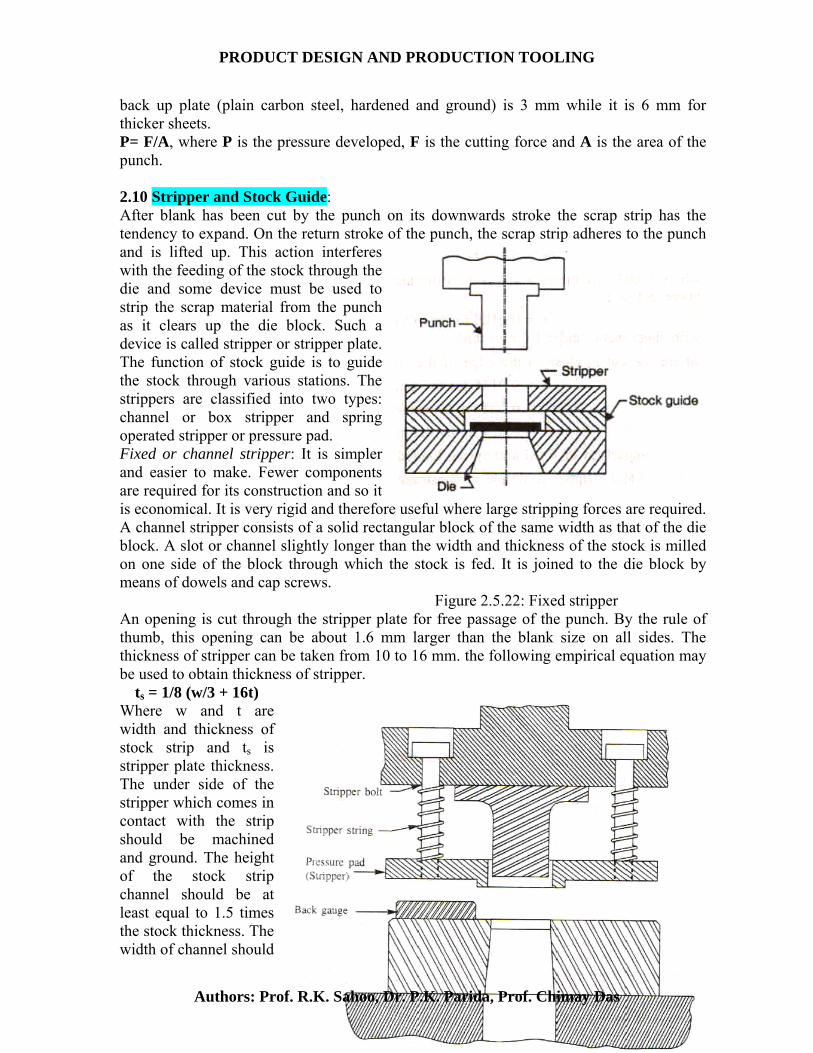
back up plate (plain carbon steel, hardened and ground) is 3 mm while it is 6 mm for thicker sheets. P= F/A, where P is the pressure developed, F is the cutting force and A is the area of the punch. 2.10 Stripper and Stock Guide: After blank has been cut by the punch on its downwards stroke the scrap strip has the tendency to expand. On the return stroke of the punch, the scrap strip adheres to the punch and is lifted up. This action interferes with the feeding of the stock through the die and some device must be used to strip the scrap material from the punch as it clears up the die block. Such a device is called stripper or stripper plate. The function of stock guide is to guide the stock through various stations. The strippers are classified into two types: channel or box stripper and spring operated stripper or pressure pad. Fixed or channel stripper: It is simpler and easier to make. Fewer components are required for its construction and so it is economical. It is very rigid and therefore useful where large stripping forces are required. A channel stripper consists of a solid rectangular block of the same width as that of the die block. A slot or channel slightly longer than the width and thickness of the stock is milled on one side of the block through which the stock is fed. It is joined to the die block by means of dowels and cap screws. Figure 2.5.22: Fixed stripper An opening is cut through the stripper plate for free passage of the punch. By the rule of thumb, this opening can be about 1.6 mm larger than the blank size on all sides. The thickness of stripper can be taken from 10 to 16 mm. the following empirical equation may be used to obtain thickness of stripper.
ts = 1/8 (w/3 + 16t)
Where w and t are width and thickness of stock strip and ts is stripper plate thickness. The under side of the stripper which comes in contact with the strip should be machined and ground. The height of the stock strip channel should be at least equal to 1.5 times the stock thickness. The width of channel should
Authors: Prof. R.K. Sahoo, Dr. P.K. Parida, Prof. Chimay Das

PRODUCT DESIGN AND PRODUCTION TOOLING
be equal to the width of the stock plus adequate clearance. The material for channel stripper is generally cold rolled mild steel. The disadvantages of this stripper are that it hides the work from the operator and it would interfere with removal of the scrap in large blanking operation. Spring loaded stripper or pressure pads: It provides a holding pressure on the stock besides the stripping action. Therefore it is employed in applications where it is desirable to keep the stock flat during punching or blanking operation. Other advantages of this stripper are the better visibility of die block and stock before the commencement of the punching action. The guiding of the stock on the die is made by means of a back gauge fixed to the die plate. Figure 2.5.23: Spring loaded stripper 2.11 Stock stop: The strip of sheet metal is fed and guided through a slot in the stock guide or through a slot in the stripper plate. After each blanking, the strip has to be advanced a correct distance. The device used to achieve this is called stock stop. This is required when the stock is fed manually. In the case of automatic feeding, stops are usually not needed as the strip can be advanced quite accurately. The simplest arrangement may be a dowel pin or a small block, against which an edge of the previously blanked hole is pushed after each stroke of the press. On its upward stroke, the punch carries the stock strip as far as the underside of the stripper plate. Due to this the stock strip gets released from the stop. With constant pressure exerted pushing the stock strip to the left, the stock will move as it is lifted clear, then drop with the next hole over the stop as the scrap strip is stripped from the punch as shown in Figure 2.5.24.
Figure 2.11: Stock stop
The above stock stop is suitable for low or medium volume of productions. The other of stock stops are latch stop, automatic stop, shoulder stop, starting stop, forward stop, backward stop, trigger stop, side cutting stop, stage stop etc. 2.12 Knock out:
Authors: Prof. R.K. Sahoo, Dr. P.K. Parida, Prof. Chimay Das

PRODUCT DESIGN AND PRODUCTION TOOLING
The function of a knockout is to shed or eject a workpiece from within the die cavity as the workpiece may get jammed in the die cavity due to friction. A knockout may be actuated by springs (shedder) or a positive acting knock out pin and bar arrangement. The knock out pin leads through the shank. It may be a single pin or a double pin fastened to a pad or collar above the shank. The working of a positive knock out pin arrangement is given in Figure 2.12 for an inverted die press. On the return stroke of the press, the knock out strikes the knockout bar. This makes the knock out pin strikes the knock out bar. The knock out plate is then activated and it forces the blank out of the die opening.
Figure 2.12: Knock out 2.13 Die Set: The die shoe, the punch shoe together with two or more guide posts constitute a die set. The die shoe and the punch shoe are made of cast iron, cast steel or rolled steel. For smaller dies cast iron is used whereas for larger dies cast steel or rolled steel may be preferred. Bushings are assembled to the upper or punch shoe by press fitting and the guide posts are press fitted into the lower of die shoe. The bushings and the posts are sized to provide a slip fit. For average range of die sets, the diameter of guide posts mat vary from 25 to 75 mm. Larger pins may be used if extreme alignment is required. When die is fully closed, the upper ends of the guide posts should not project beyond the top surface of the punch shoe.
The die shoe thickness generally varies from 40 mm to 150 mm depending on the cutting force produced. If cast iron is used, then it should be thicker than cast steel or rolled steel shoes to provide the same mechanical strength and resistance to deflection. The punch holder thickness is 13 to 25 mm thinner than die shoe thickness because the punch shoe is firmly backed up by the ram, whereas the die shoe is often over a hole in the press bed. The thickness of the shoe is limited by the shut height of the press.
Figure 2.13: Die set
Authors: Prof. R.K. Sahoo, Dr. P.K. Parida, Prof. Chimay Das

PRODUCT DESIGN AND PRODUCTION TOOLING
2.14 Centre of Pressure: When the shape of the blank to be cut is irregular, the summation of shear forces about the centreline of the press ram may not be symmetrical. Due to this, bending moments will be introduced in the press ram, producing misalignment and undesirable deflections. To avoid this centre of pressure of the shearing action of the die must be found and while laying out the punch position on the punch shoe, it should be ensured that the centreline of the press ram passes through the centre of pressure of the blank. This centre of pressure is the centroid of the line perimeter of the blank.
X = (l1x1 + l2x2 + l3x3 ….) / l1 + l2 + l3 …. Y= (l1y1 + l2y2 + l3y3 ….) / l1 + l2 + l3 …. Where X= x distance to centre of pressure
Y= y distance to centre of pressure 2.15 Bolster Plate: When many dies are to run in the same press at different times, the wear occurring on the press bed is high. The bolster plate is incorporated to take this wear. It is attached to the press bed and the die shoe is attached to it. It is machined so that its surfaces are flat and parallel. Bolster plate thickness varies from 25 to 75 mm and is relatively cheap and easy to replace. Some other functions of bolster plate are:
• To provide attachment holes for the dies rather than drilling these holes in the press bed.
• To support the die shoe when it is located over a large hole in the press bed. • To take up space in the press when the press shut height is too large compared to
the die shut height. • To provide chutes for ejecting parts or scrap out the sides of the press.
The material for bolster plate is good quality steel. 2.16 Shut Height of Press: it is the height of the opening between the ram and the bed, with ram down and adjustment up. Adjustment is used to change the opening of a press. This can only decrease the opening from the maximum shut height but it does not increase upon the shut height. 2.17 Shut height of Die: It is the distance between the top of the punch shoe and the bottom of the die shoe. Die Shut Height = punch shoe thickness + Die shoe thickness + Die block height + Punch length – bypass of punch and die. The shut height of the die must be equal or less than the shut height of the press by 5 to 10 mm. If the die shut height is less than the press shut height by an amount greater than the press adjustment, then bolster plate may be used to take up the gap space. If the shut height of the die is greater than that of press, then die block height, punch length, die shoe and punch shoe thickness may be reduced using better material if possible. However minimum design requirements should not be violated. If necessary a new press must be selected to suit the die rather than altering the original design.
Authors: Prof. R.K. Sahoo, Dr. P.K. Parida, Prof. Chimay Das

PRODUCT DESIGN AND PRODUCTION TOOLING
MODULE – III
3.1 JIGS AND FIXTURES
Fixtures: These strong and rigid mechanical devices used in machine shop enable easy, quick and consistently accurate locating, supporting and clamping, blank against cutting tool(s) and result faster and accurate machining with consistent quality, functional ability and interchangeability. It holds the workpiece securely in the correct position with respect to the machine or cutter during the operation. There is sometimes a provision in the fixture for setting the tool with respect to the workpiece but tool is not guided. Fixtures are often clamped to the machine table. Jigs: It is a fixture with an additional feature of tool guidance such as drill bushes. These direct the tool to the correct position on the workpiece. Jigs are rarely clamped on the machine table because it is necessary to move the jig on the table to align the various bushes in the jig with the machine spindle.
Figure 3.1 Jigs and Fixtures
Many operations like loading and unloading of the work pieces, alignment of
tools with work pieces, measurement of dimensions, marking, punching, supporting, clamping, etc. are needed to be carried out carefully and skillfully by the machinist or operator for simple jobs in the shop floor. Even after that there may be inaccuracies in machining. Such tedious and time consuming manual work are eliminated or drastically reduced in mass production by automatic or special purpose machine tools. But such machine tools are quite expensive and hence are economically justified for only huge or mass production and not viable for small lot or batch production. For batch production proper design and use of simple but effective jigs and fixtures are appropriate and economically justified. The basic purposes of developing and using suitable jigs and fixtures for batch production in machine shops are: • to eliminate marking, punching, positioning, alignments etc.; • easy, quick and consistently accurate locating, supporting and clamping the blank in alignment of the cutting tool; • guidance to the cutting tool like drill, reamer etc.; • increase in productivity and maintain product quality consistently; • to reduce operator’s labour and skill requirements;
Authors: Prof. R.K. Sahoo, Dr. P.K. Parida, Prof. Chimay Das

PRODUCT DESIGN AND PRODUCTION TOOLING
• to reduce measurement and its cost; • enhancing technological capacity of the machine tools; • reduction of overall machining cost and also increase in interchangeability. 3.1.1 Design Considerations for Jigs and Fixtures Jigs and fixtures are manually or partially power operated devices. To fulfil their basic purposes, jigs and fixtures are comprised of several elements which are mentioned below.
• base and body or frame with clamping features • locating elements for proper positioning and orientation of the blank • supporting surfaces and base • clamping elements • tool guiding frame and bushes (for jig) • indexing plates or systems, if necessary • auxiliary elements • fastening parts
Figure 3.1.1: Role of jigs and fixtures on machining cost
Authors: Prof. R.K. Sahoo, Dr. P.K. Parida, Prof. Chimay Das

PRODUCT DESIGN AND PRODUCTION TOOLING
Figure 3.1.2: Major elements of Jigs and Fixtures
Therefore keeping in view increase in productivity, product quality, repeatability i.e.
interchangeability and overall economy in batch production by machining, the following factors are essentially considered during design, fabrication and assembly of jigs and fixtures:
• easy, quick and consistently accurate locating of the blank in the jig or fixture in reference to the cutting tool
• providing strong, rigid and stable support to the blank • quick, strong and rigid clamping of the blank in the jig or fixture without
interrupting any other operations • tool guidance for slender cutting tools like drills and reamers • easy and quick loading and unloading the job to and from the jig or fixture • use of minimum number of parts for making the jig or fixture • use of standard parts as much as possible • reasonable amount of flexibility or adjustability, if feasible, to accommodate
slight variation in the job - dimensions. • prevention of jamming of chips, i.e. wide chips-space and easy chip disposal • easy, quick and accurate indexing system if required. • easy and safe handling and moving the jig or fixture on the machine table, i.e.,
their shape, size, weight and sharp edges and corners • easy and quick removal and replacement of small parts • manufacturability i.e. ease of manufacture • durability and maintainability • service life and overall expenses
3.1.3 Principles and Methods of Locating, Supporting and Clamping Blanks and Tool Guidance in Jigs and Fixtures It is already emphasized that the main functions of the jigs and fixtures are: (a) easily, quickly, firmly and consistently accurately • locating • supporting and
Authors: Prof. R.K. Sahoo, Dr. P.K. Parida, Prof. Chimay Das

PRODUCT DESIGN AND PRODUCTION TOOLING
• clamping the blank (in the jig or fixture) in respect to the cutting tool(s) (b) providing guidance to the slender cutting tools using proper bushes.
There are and can be several methods of locating, supporting and clamping depending upon the size, shape and material of the job, cutting tool and the machining work required. But some basic principles or rules are usually followed while designing for locating, supporting and clamping of blank in fixtures. 3.1.4 Principles of Location: The locating surface on the work piece can be selected considering following principles.
• Law of arithmetic superiority: It states that select a surface of the workpiece which has largest dimensions. But this law may not be followed in some cases as illustrated below.
The drawing clearly states that hole C should be at a distance of D from face A. Consequently, we must use face A as a datum for locating the work piece while drilling hole C. This would ensure that hole C is at a distance D from face A. If we use face B as locating surface, the variation in length L would cause inaccuracies in the position of hole C. if length L is oversized by 1 mm, hole C will be at (D+1) mm from face a. If length L is undersized the hole would shift towards face a and would be nearer than distance D from face A. If we locate on face A the hole would be always at distance D from face A irrespective of the variation in length L. So a smaller plane A is selected as locating surface compared to a bigger plane B.
Figure 3.1.4: Locating surfaces 3.1.5 Types of surfaces:
1. Datum surfaces: These are real or imaginary surfaces to which various features of a part are dimensionally related. Preferably these should be real planes so that actual measurement can be made from them. The central axis of a hole is an imaginary datum line.
2. Functional surfaces: These are those surfaces which enter into operation of the components. Datum and functional surfaces are called critical surfaces from which locations are taken.
3. Clearance surfaces: These surfaces provide continuity in the part and have no functional requirement.
4. Atmospheric surfaces: These have neither contact relationship nor proximity to the surfaces of other parts of the workpiece.
Authors: Prof. R.K. Sahoo, Dr. P.K. Parida, Prof. Chimay Das

PRODUCT DESIGN AND PRODUCTION TOOLING
Figure 3.1.5: Types of surfaces Figure 3.1.6: Law of geometric superiority 3.1.6 Law of geometric superiority: This states that select the surface which is
geometrically related to the maximum number of machined surfaces. • Law of mechanical superiority: This law states that select a surface which is
mechanically stronger. • Tolerance stacking: Always consider the surface from which the dimensions and
tolerances have been mentioned in the drawing as locating surface. Locating Methods: After locating surfaces on the workpiece have been established, next step is to adopt a suitable locating method. A workpiece can be located from:
1. Plane surface 2. Profile and 3. Cylindrical surface
3.1.7 Location from Plane Surface: For accurate machining, the workpiece is to be placed and held in correct position and orientation in the fixture (or jig) which is again appropriately located and fixed with respect to the cutting tool and the machine tool. It has to be assured that the blank, once fixed or clamped, does not move at all. Any solid body may have maximum twelve degrees of freedom as indicated in figure 3.1.7. By properly locating, supporting and clamping the blank its all degrees of freedom are to be arrested.
In a state of freedom, the workpiece may move in either of the two opposed directions along three mutually perpendicular axes, XX, YY and ZZ. These six movements are called movement of translation. The workpiece can rotate in either of two opposed directions around each axis, clockwise and anticlockwise. These six movements are called rotational movements. To restrict various degrees of freedom one simple arrangement is shown in figure 3.1.8.
Authors: Prof. R.K. Sahoo, Dr. P.K. Parida, Prof. Chimay Das

PRODUCT DESIGN AND PRODUCTION TOOLING
a) The workpiece is resting on three pins A, B, C which are inserted in the base of the fixed body. It cannot rotate about axes XX and YY and also it cannot move downward. In this way five degrees of freedom are arrested. Figure 3.1.7: Workpiece in space b) Two more pins D and E are inserted in the fixed body, in a plane perpendicular to the plane containing the pins A, B, C. Now the workpiece cannot rotate about the ZZ axis and it cannot move towards the left. So three more degrees of freedom are restricted. c) Another pin F in the second vertical plane of the fixed body arrests one degree of freedom by restricting translational movement along negative XX axis. Thus six locating pins in three mutually perpendicular planes restrict nine degrees of freedom. To restrict remaining three degrees of freedom we require three more pins in three mutually perpendicular planes. But this will completely enclose the workpiece making its loading and unloading into the jig or fixture impossible. Due to this, these remaining degrees of freedom may be arrested by means of a clamping device. The above method of locating a work piece in a jig or fixture is called
Figure 3.1.8: Workpiece located in a fixture 3-2-1 principle or six point location principle.
Authors: Prof. R.K. Sahoo, Dr. P.K. Parida, Prof. Chimay Das

PRODUCT DESIGN AND PRODUCTION TOOLING
Figure 3.1.9: Sighting location Figure 3.1.10: Profile location by pins
Location from Profile: For simple components where appearance is important, a sighting plate can be provided. It is slightly bigger than the workpiece. The workpiece can be positioned on the sighting plate in such a way that there is equal margin on all the sides as shown in the figure 3.1.9. The profile of a workpiece can be located by confining the profile with cylindrical locating pins as given in figure 3.1.10. The profile can also be located by providing a pocket or nest around the profile of the workpiece (figure3.1.11). The inside profile of the nest should be lesser than the workpiece to permit grip over the workpiece for unloading. For thin sheet metal workpieces, finger slots or ejection arrangement should be provided for unloading the workpiece. Alternatively, a partial nest can be used. Sheet metal blanks from the same die or die cast components from the same mould are almost identical. Such workpieces with little variation can be located precisely by a close fitting nest.
Figure 3.1.11: Location nests
Authors: Prof. R.K. Sahoo, Dr. P.K. Parida, Prof. Chimay Das

PRODUCT DESIGN AND PRODUCTION TOOLING
Location from Cylindrical Profiles (shaft and hole): Workpieces such as connecting rod or lever, which have previously machined and finished holes may be located with the help of cylindrical pins projecting from the base surface of a jig or fixture, which will fit into the holes in the workpiece.
The side figure shows a workpiece with one machined hole. The base plate prevents five degrees of freedom. The pin A which is inside the existing hole will prevent four translational movements. But swiveling of workpiece about the central axis of pin A and upward movement are free. Rotation about the axis of pin A can be restricted by two pins B as shown in the figure. The last degree of freedom can be taken care by clamping.
Figure 3.1.12: Location of workpiece with one hole When we have to use two holes in a workpiece for location, we must take into account the variation in the centre distance of then two holes due to wear of the guide bushes for cutting tools. This variation can be taken care of by making one of the two location pins flattened or
diamond shaped as shown in adjacent figure. Out of the two holes, the important and accurate one should be used for principal
cylindrical location with a full pin. The diamond shaped pin should be used to
Figure 3.1.13: Diamond pin application constrain pivoting of the workpiece around the principal locator. The principal locator should be longer than diamond pin so that the workpiece can be located and pivoted
Authors: Prof. R.K. Sahoo, Dr. P.K. Parida, Prof. Chimay Das

PRODUCT DESIGN AND PRODUCTION TOOLING
around it before engaging with the diamond pin. This simplifies and speeds up loading of the workpiece. Diamond pin can also be used for accommodating the variation in the distance of a hole from a plane surface.
Let us consider the tolerance for centreline distance between holes and pins are a and b respectively. If the centreline distance between
the holes is at maximum and it is of minimum value between the pins, then a situation will arise where the allowance between hole and second pin would become a plus b (V). If that allowance is not provided then second pin may not enter the second hole. But if that allowance is large then the workpiece may swivel around the principal locator pin. To prevent this undesirable swiveling action the second pin is relieved on two sides perpendicular to the X axis. This will allow for variation in the X direction
but Figure 3.1.14: Diamond pin locators will provide cylindrical locating surfaces in the Y direction. The locating surface of a diamond pin is usually less than 8 % of a full cylindrical pin. This provides more clearance at location points. Clearance V at the corner Q is much more than radial clearance (D-d/2) between the workpiece hole and the diamond pin. Referring to figure 3.1.16 in triangle PRS: (PS)2 = (PR)2 + (RS)2
= (PQ +QR)2 + ( QS – QR)2
{ D/2}2 = { V + W/2}2 + { d/2}2 – { W/2}2
= V2 + VW + W2/4 + d2/4 - W2/4 d = 2 [ D2/4 – VW – V2] ½ , where d= diamond pin diameter Figure 3.1.15: Diamond pin
Authors: Prof. R.K. Sahoo, Dr. P.K. Parida, Prof. Chimay Das

PRODUCT DESIGN AND PRODUCTION TOOLING
Location land W of diamond pin should be square to the axis along which variation V occurs. When a diamond pin is used to locate the axis of two cylindrical holes, the land should be square to the axis joining the centres of the holes. While locating a plane surface and a hole, the centreline of land W should be parallel to the plane surface.
W = s
dDD2
)(2 − - 2s
Where s =Total axial shift= a + b
Figure 3.1.16: Principle of diamond pin
Authors: Prof. R.K. Sahoo, Dr. P.K. Parida, Prof. Chimay Das