11 3211654 en om - welikebikes...enormous pleasure if you service and maintain it accordingly. we...
TRANSCRIPT

OWNER'S MANUAL 2011690 Enduro R USA
Art. no. 3211654en


DEAR KTM CUSTOMER 1
DEAR KTM CUSTOMER
Congratulations on your decision to buy a KTM motorcycle. You are now the owner of a state-of-the-art sports motorcycle that will give youenormous pleasure if you service and maintain it accordingly.
We wish you a lot of enjoyment in riding this vehicle!
Enter the serial numbers of your vehicle below.
Chassis number ( p. 24) Dealer's stamp
Engine number ( p. 25)
Key number ( p. 25)
The owner's manual corresponded to the latest state of this series at the time of printing. Slight deviations resulting from continuing devel-opment and design of our vehicles cannot, however, be completely excluded.
All specifications are non-binding. KTM Sportmotorcycle AG specifically reserves the right to modify or delete technical specifications,prices, colors, forms, materials, services, designs, equipment, etc., without prior notice and without specifying reasons, to adapt theseto local conditions, as well as to stop production of a particular model without prior notice. KTM accepts no liability for delivery options,deviations from illustrations and descriptions, as well as misprints and other errors. The models portrayed partly contain special equipmentthat does not belong to the regular scope of delivery.

DEAR KTM CUSTOMER 2
© 2010 KTM-Sportmotorcycle AG, Mattighofen AustriaAll rights reservedReproduction, even in part, as well as copying of all kinds, is permitted only with the express written permission of the copyright owner.
ISO 9001(12 100 6061)According to the international quality management standard ISO 9001, KTM uses quality assurance processes that lead tothe maximum possible quality of the products.Issued by: TÜV Management Service
KTM-Sportmotorcycle AG5230 Mattighofen, Austria

TABLE OF CONTENTS 3
TABLE OF CONTENTS
MEANS OF REPRESENTATION ............................................... 7IMPORTANT INFORMATION ................................................... 8
Overview of warning labels................................................. 12VIEW OF VEHICLE................................................................ 20
View of vehicle, front left................................................... 20View of vehicle, rear right .................................................. 22
SERIAL NUMBERS............................................................... 24Chassis number................................................................ 24Type label........................................................................ 24Engine number................................................................. 25Key number ..................................................................... 25Fork part number.............................................................. 26Shock absorber part number.............................................. 26
CONTROLS.......................................................................... 27Clutch lever ..................................................................... 27Hand brake lever .............................................................. 27Throttle grip..................................................................... 28Light switch ..................................................................... 28Turn signal switch ............................................................ 29Horn button ..................................................................... 29Emergency OFF switch...................................................... 30Electric starter button ....................................................... 30Ignition/steering lock ........................................................ 31Combination instrument.................................................... 31Combination instrument - function buttons ......................... 32Combination instrument - indicator lamps........................... 32Combination instrument - display....................................... 33Combination instrument - speedometer............................... 34Setting kilometers or miles ................................................ 34
Combination instrument - time .......................................... 35Setting the clock .............................................................. 35Combination instrument - display ODO ............................... 36Combination instrument - setting/resetting TRIP 1............... 36Combination instrument - setting/resetting TRIP 2............... 37Combination instrument - TRIP F display............................ 38Combination instrument - coolant temperature indicator ...... 38Opening the filler cap ....................................................... 39Closing filler cap .............................................................. 40Seat release ..................................................................... 40Handrails......................................................................... 41Passenger footrests........................................................... 41Shift lever........................................................................ 42Foot brake lever................................................................ 43Side stand ....................................................................... 43
PUTTING INTO OPERATION.................................................. 44Advice on first use............................................................ 44Running in the engine....................................................... 45Loading the vehicle .......................................................... 46
RIDING INSTRUCTIONS ....................................................... 48Performing checks and vehicle care when preparing foruse ................................................................................. 48Starting ........................................................................... 49Starting off ...................................................................... 50Shifting, riding................................................................. 50Braking ........................................................................... 54Stopping, parking ............................................................. 55Refueling......................................................................... 56

TABLE OF CONTENTS 4
SERVICE SCHEDULE............................................................ 59Service schedule .............................................................. 59
TUNING THE CHASSIS......................................................... 62Fork/shock absorber.......................................................... 62Adjusting the compression damping of the fork ................... 62Adjusting the rebound damping of the fork.......................... 63Compression damping of the shock absorber ....................... 64Adjusting the low-speed compression damping of the shockabsorber .......................................................................... 64Adjusting the high-speed compression damping of theshock absorber ................................................................. 65Adjusting the rebound damping of the shock absorber.......... 66Measuring the unloaded rear wheel sag............................... 67Checking the static sag of the shock absorber ..................... 68Checking the riding sag of the shock absorber ..................... 69Adjusting the spring preload of the shock absorberx ......... 69Handlebar position ........................................................... 71Adjusting handlebar positionx ........................................ 71
SERVICE WORK ON THE CHASSIS........................................ 73Raising the motorcycle with the lift stand ........................... 73Removing the motorcycle from the lift stand ....................... 73Bleeding the fork legs ....................................................... 74Cleaning the dust boots of the fork legs .............................. 74Loosening the fork protection............................................. 75Positioning the fork protection ........................................... 76Checking the steering head bearing play ............................. 76Adjusting the play of the steering head bearingx .............. 77Removing the seat ............................................................ 78Mounting the seat ............................................................ 79
Removing the air filterx ................................................. 79Installing the air filterx .................................................. 80Checking the chain for dirt ................................................ 81Cleaning the chain............................................................ 81Checking the chain tension ............................................... 83Adjusting the chain tension ............................................... 84Check the chain, rear sprocket, engine sprocket and chainguide............................................................................... 86Adjusting chain guidex .................................................. 91Adjusting basic position of clutch lever............................... 92Checking/rectifying the fluid level of the hydraulic clutch ..... 92Removing the engine guard ............................................... 93Installing the engine guard ................................................ 94
BRAKES.............................................................................. 95Checking the free travel of the hand brake lever .................. 95Adjusting the free travel of the hand brake lever .................. 95Checking the brake discs................................................... 96Checking the front brake fluid level .................................... 97Adding front brake fluidx ............................................... 98Checking the front brake linings......................................... 99Changing the front brake liningsx ................................. 100Checking the free travel of foot brake lever........................ 104Adjusting the basic position of the foot brake leverx ....... 104Checking rear brake fluid level......................................... 105Adding rear brake fluidx .............................................. 106Checking the rear brake linings ........................................ 108Changing the rear brake liningsx................................... 108
WHEELS, TIRES ................................................................ 112Removing the front wheelx ........................................... 112

TABLE OF CONTENTS 5
Installing the front wheelx............................................ 113Removing rear wheelx.................................................. 115Installing the rear wheelx ............................................. 116Checking the rear hub rubber dampersx ........................ 117Checking the tire condition.............................................. 118Checking the tire air pressure .......................................... 120Checking the spoke tension ............................................. 121
ELECTRICAL SYSTEM ........................................................ 123Removing the batteryx ................................................. 123Installing the batteryx.................................................. 124Recharging the batteryx ............................................... 124Changing the main fuse .................................................. 126Changing fuses of individual power consumers .................. 128Removing the headlight mask with the headlight ............... 130Installing the headlight mask with the headlight ................ 132Changing the headlight bulb............................................ 133Changing the parking light bulb ....................................... 134Changing the turn signal bulb .......................................... 135Changing the tail light..................................................... 136Checking the headlight setting......................................... 137Adjusting the headlight range .......................................... 137
COOLING SYSTEM ............................................................. 139Cooling system............................................................... 139Checking the antifreeze and coolant level ......................... 139Checking the coolant level............................................... 141Draining the coolantx .................................................. 143Filling the cooling systemx ........................................... 144
TUNING THE ENGINE ........................................................ 146Checking the play in the throttle cable.............................. 146
Adjusting the play in the throttle cablex ........................ 147Adjusting the engine characteristic................................... 147
SERVICE WORK ON THE ENGINE ....................................... 149Checking the engine oil level ........................................... 149Changing the engine oil and filter, cleaning the oilscreensx..................................................................... 150Draining the engine oilx ............................................... 150Removing the oil filterx................................................ 151Cleaning the oil screensx ............................................. 153Installing the oil filterx ................................................ 155Filling up with engine oilx ............................................ 155Adding engine oil ........................................................... 156
CLEANING, CARE .............................................................. 158Cleaning the motorcycle .................................................. 158Protective treatment for winter operation .......................... 160
STORAGE .......................................................................... 161Storage.......................................................................... 161Preparing for use after storage ......................................... 162
TROUBLESHOOTING.......................................................... 163BLINK CODE ..................................................................... 166TECHNICAL DATA - ENGINE............................................... 171
Capacity - engine oil ....................................................... 172Capacity - coolant........................................................... 172
TECHNICAL DATA - ENGINE TIGHTENING TORQUES........... 173TECHNICAL DATA - CHASSIS ............................................. 176
Lighting equipment ........................................................ 177Tires ............................................................................. 178Capacity - fuel................................................................ 178
TECHNICAL DATA - FORK................................................... 179

TABLE OF CONTENTS 6
TECHNICAL DATA - SHOCK ABSORBER .............................. 180TECHNICAL DATA - CHASSIS TIGHTENING TORQUES ......... 182SUBSTANCES.................................................................... 185AUXILIARY SUBSTANCES................................................... 189STANDARDS...................................................................... 191INDEX ............................................................................... 192

MEANS OF REPRESENTATION 7
Symbols usedThe meaning of specific symbols is described below.
Indicates an expected reaction (e.g. of a work step or a function).
Indicates an unexpected reaction (e.g. of a work step or a function).
All work marked with this symbol requires specialist knowledge and technical understanding. In the interest of yourown safety, have these jobs performed in an authorized KTM workshop! There, your motorcycle will be serviced opti-mally by specially trained experts using the specialist tools required.
Indicates a page reference (more information is provided on the specified page).
Formats usedThe following typographical formats are used.
Specific name Identifies a proprietary name.
Name® Identifies a protected name.
Brand™ Identifies a brand in merchandise traffic.

IMPORTANT INFORMATION 8
Use definitionKTM sport motorcycles are designed and constructed to meet the normal demands of regular road and light offroad operation (dirt roads),but not for use on race courses.
InfoThe motorcycle is authorized for public road traffic in the homologous version only.
ServiceA prerequisite for fault-free operation and avoiding premature wear is compliance with the instructions for maintenance, care and tuning ofthe engine and suspension provided in the owner's manual. Poor adjustment and tuning of the engine and chassis can lead to damage andbreakage of components.Using the motorcycle in extreme conditions such as very muddy or wet roads can lead to above-average wear of components such as thetransmission train or the brakes. For this reason, it may be necessary to service or replace worn parts before the limit specified in the ser-vice schedule is reached.It is imperative that you adhere to the stipulated run-in times and service intervals. If you observe these exactly, you will ensure a muchlonger service life for your motorcycle.
WarrantyThe work prescribed in the service plan must only be carried out in an authorized KTM workshop and confirmed in the service record; oth-erwise all warranty claims will be disregarded. No warranty claim can be met for damage resulting from manipulation and/or other changesto the vehicle.
Fuel, oils, etc.You should use the fuels, oils and greases according to specifications as listed in the owner's manual.

IMPORTANT INFORMATION 9
Spare parts, accessoriesFor your own safety, only use spare parts and accessory products that have been approved and/or recommended by KTM and have theminstalled by an authorized KTM workshop. KTM accepts no liability for other products and any resulting damage.Some spare parts and accessory products are specified in parentheses in the descriptions. Your KTM dealer will be glad to advise you.
You will find the current KTM PowerParts for your vehicle on the KTM website.International KTM Website: http://www.ktm.com
Work rulesSpecial tools are necessary for certain tasks. The tools are not contained in the vehicle but can be ordered under the number in parenthe-ses. Example: valve spring mounter (59029019000)During assembly, non-reusable parts (e.g. self-locking screws and nuts, seals and seal rings, O-rings, pins, lock washers) must be replacedby new parts.If a thread lock (e.g. Loctite®) is used for screw connections, be sure to comply with the manufacturer's specific instructions on its usage.Parts that you want to reuse following repairs and servicing should be cleaned and checked for damage and wear. Change damaged orworn parts.Ensure that the vehicle is roadworthy after completing repair and maintenance work.
Transport
NoteDanger of damage The parked vehicle may roll away or fall over.
– Always place the vehicle on a firm and even surface.
NoteFire hazard Some vehicle components become very hot when the vehicle is operated.
– Do not park the vehicle near flammable or explosive substances. Do not place objects on the vehicle while it is still warm from beingrun. Always let the vehicle cool first.

IMPORTANT INFORMATION 10
– Switch off the engine and remove the ignition key.
– Use straps or other suitable devices to secure the motorcycle against accidents or falling over.
EnvironmentOffroad motorcycling is a wonderful sport and we naturally hope that you will be able to enjoy it to the fullest. However, it is a potentialproblem for the environment and can lead to conflicts with other persons. But if you use your motorcycle responsibly, you can ensure thatsuch problems and conflicts do not have to occur. To protect the future of motorcycle sport, make sure that you use your motorcyclelegally, display environmental consciousness, and respect the rights of others.

IMPORTANT INFORMATION 11

IMPORTANT INFORMATION 12
2.1Overview of warning labels
800103-10

IMPORTANT INFORMATION 13
1 Type label, Canada
2 Type label, USA
3 Information, emission control
4 Information, noise emission
5 Information, suspension setting
6 Information, chain tension
7 Information, fuel evaporation system
8 Information, putting into operation
800110-01
Type label, Canada

IMPORTANT INFORMATION 14
B00112-01
Type label, USA
101072-01
Information, emission control

IMPORTANT INFORMATION 15
101074-01
Information, noise emission
B00111-01
Information, suspension setting

IMPORTANT INFORMATION 16
100338-01
Information, chain tension
101073-01
Information, fuel evaporation system
700210-01
Information, putting into operation

IMPORTANT INFORMATION 17
Notes/warningsPay close attention to the notes/warnings.
InfoVarious information and warning labels are affixed to the vehicle. Do not remove information/warning labels. If they are missing,you or others may not recognize potential hazards and may therefore be injured.
Grades of risks
DangerIdentifies a danger that will immediately and invariably lead to fatal or serious permanent injury if the appropriate measures are nottaken.
WarningIdentifies a danger that is likely to lead to fatal or serious injury if the appropriate measures are not taken.
CautionIdentifies a danger that may lead to minor injuries if the appropriate measures are not taken.
NoteIdentifies a danger that will lead to considerable machine and material damage if the appropriate measures are not taken.
WarningIdentifies a danger that will lead to environmental damage if the appropriate measures are not taken.

IMPORTANT INFORMATION 18
Owner's manual– It is important that you read this owner's manual carefully and completely before making your first trip. It contains useful information
and tips to help you operate and handle your motorcycle. Only then will you find out how to customize the motorcycle ideally for yourown use and how you can protect yourself from injury. The owner's manual also contains important information on servicing the motor-cycle.
– The owner's manual is an important component of the motorcycle and should be handed over to the new owner if the vehicle is sold.
Reporting safety defectsIf you believe that your vehicle has a defect which could cause an accident resulting in injury or death, you should immediately inform theNational Highway Traffic Safety Administration (NHTSA) in addition to notifying KTM North America, Inc.If NHTSA receives similar complaints, it may open an investigation, and if it finds that a safety defect exists in a group of vehicles, it mayorder a recall and remady campaign. However, NHTSA cannot become involved in individual problems between you, your dealer, or KTMNorth America, Inc.To contact NHTSA, you may either call the Auto Safety Hotline toll-free at 1–888–327–4236 or visit the website www.nhtsa.dot.gov, orwrite to: NHTSA Headquarters, 1200 New Jersey Avenue, SE, West Building, Washington, DC 20590. You can also obtain other informa-tion about motor vehicle safety from the Hotline.
Noise emission warrantyKTM Sportmotorcycle AG warrants that this exhaust system, at the time of sale, meets all applicable U.S. EPA Federal noise standards.This warranty extends to the first person who buys this exhaust system for purposes other than resale, and to all subsequent buyers.Warranty claims should be directed to:KTM North America, Inc., Customer Support, 1119 Milan Ave., Amherst, OH 44001, USAPhone: (440) 985–3553www.ktmusa.comKTM Canada, Inc., Customer Support, 1375-1 Marie-Victorin, Saint-Bruno, QC J3V 6B7Phone: (450) 441–4451 x 4250www.ktmcanada.com

IMPORTANT INFORMATION 19
Tampering warningTampering with noise control system prohibited. Federal law prohibits the following acts or causing thereof:
1 The removal or rendering inoperative by any person other than for purposes of maintenance, repair, or replacement, of any device orelement of design incorporated into any new vehicle for the purpose of noise control prior to its sale or delivery to the ultimate pur-chaser or while it is in use, or
2 the use of the vehicle after such device or element of design has been removed or rendered inoperative by any person.
Among those acts presumed to constitute tampering are the acts listed below.
1 Removal of, or puncturing the muffler, baffles, header pipes or any other components which conducts exhaust gases.
2 Removal or puncturing of any part of the intake system.
3 Lack of proper maintenance.
4 Replacing any moving part of the vehicle, or parts of the exhaust or intake system, with parts other than those specified by the manu-facturer.
Warning, operating noiseThis product should be checked for repair or replacement if the motorcycle noise has increased significantly through use. Otherwise, theowner may become subject to penalties under state and local ordinances.
Consumer rightsWarranty claims should be directed to an authorized KTM workshop. If you are not satisfied, please contact:KTM North America, Inc., Customer Support, 1119 Milan Ave., Amherst, OH 44001, USAPhone: (440) 985–3553www.ktmusa.comKTM Canada, Inc., Customer Support, 1375-1 Marie-Victorin, Saint-Bruno, QC J3V 6B7Phone: (450) 441–4451 x 4250www.ktmcanada.comYour rights may vary depending on national and regional laws.

VIEW OF VEHICLE 20
3.1View of vehicle, front left
800106-10

VIEW OF VEHICLE 21
1 Hand brake lever ( p. 27)
2 Clutch lever ( p. 27)
3 Handrails ( p. 41)
4 Filler cap
5 Seat
6 Engine number ( p. 25)
7 Shift lever ( p. 42)
8 Side stand ( p. 43)
9 Footrest
10 Seat release ( p. 40)

VIEW OF VEHICLE 22
3.2View of vehicle, rear right
800107-10

VIEW OF VEHICLE 23
1 Ignition/steering lock ( p. 31)
2 Rear mirror
3 Light switch ( p. 28)
3 Turn signal switch ( p. 29)
3 Horn button ( p. 29)
4 Combination instrument ( p. 31)
5 Emergency OFF switch ( p. 30)
5 Electric starter button ( p. 30)
6 Throttle grip ( p. 28)
7 Chassis number ( p. 24)
8 Passenger footrests ( p. 41)
9 Shock absorber, rebound adjustment
10 Foot brake lever ( p. 43)
11 Level viewer, engine oil

SERIAL NUMBERS 24
4.1Chassis number
101045-10
The chassis number is stamped on the steering head on the right.
4.2Type label
101046-10
Type label is located on the upper right frame tube below the seat.

SERIAL NUMBERS 25
4.3Engine number
100211-10
The engine number is stamped on the left side of the engine under the engine sprocket.
4.4Key number
100179-10
The key number can be found on the KEYCODECARD.
InfoYou need the key number to order a spare key. Keep the KEYCODECARD in a safeplace.

SERIAL NUMBERS 26
4.5Fork part number
101047-10
The fork part number is stamped on the inner side of the fork stub.
4.6Shock absorber part number
101048-10
The shock absorber part number is on the left of the shock absorber.

CONTROLS 27
5.1Clutch lever
100219-10
The clutch lever is fitted on the left side of the handlebar.The clutch is hydraulically operated and self-adjusting.
5.2Hand brake lever
100220-10
The hand break lever is fitted on the right side of the handlebar.The hand brake lever operates the front brake.

CONTROLS 28
5.3Throttle grip
101069-10
The throttle grip is fitted on the right side of the handlebar.
5.4Light switch
100222-10
The light switch is fitted on the left side of the handlebar.
Possible states
Low beam on – Light switch is turned downwards. In this position, the lowbeam and tail light are switched on.
High beam on – Light switch is turned upwards. In this position, the highbeam and the tail light are switched on.

CONTROLS 29
5.5Turn signal switch
100223-10
The turn signal switch is fitted on the left side of the handlebar.
Possible states
Turn signal off
Turn signal light, left, on – Turn signal switch pressed to the left. The turnsignal switch returns automatically to the central position after use.
Turn signal light, right, on – Turn signal switch pressed to the right. Theturn signal switch returns automatically to the central position after use.
To switch off the turn signal light, press the turn signal switch towards the switch case.
5.6Horn button
100224-10
The horn button is fitted on the left side of the handlebar.
Possible states• Horn button in neutral position• Horn button pressed – The horn is operated in this position.

CONTROLS 30
5.7Emergency OFF switch
100225-10
The emergency OFF switch is fitted on the right side of the handlebar.
Possible states
Emergency OFF switch off – In this position, the ignition circuit is inter-rupted, a running engine stops, and the engine cannot be started.
Emergency OFF switch on – This position is necessary for operation as theignition circuit is closed.
5.8Electric starter button
100226-10
The electric starter button is fitted on the right side of the handlebar.
Possible states• Electric starter button in basic position• Electric starter button pressed – In this position, the electric starter is actuated.

CONTROLS 31
5.9Ignition/steering lock
600825-01
The ignition/steering lock is located in front of the seat.
Possible states
Ignition OFF – In this position, the ignition circuit is interrupted, a runningengine stops, and a non-running engine will not start. The ignition key canbe removed.
Ignition ON – In this position, the ignition circuit is closed and the enginecan be started.
Steering locked – In this position, the ignition circuit is interrupted and thesteering locked. The ignition key can be removed.
5.10Combination instrument
800083-10
The combination instrument is installed in front of the handlebar.The combination instrument is divided into 3 function areas. Function buttons Indicator lamps Display

CONTROLS 32
5.11Combination instrument - function buttons
800083-11
You can change the display mode with the M button .Possible display modes are distance traveled (Odo), trip master 1 (Trip 1) and trip mas-ter 2 (Trip 2).Press the S button to reset the trip master 1 function (Trip 1) and trip master 2 function(Trip 2) to 0.00.
5.12Combination instrument - indicator lamps
800083-12
The indicator lamps offer additional information about the operating state of the motorcy-cle.
Possible states
The turn signal indicator light flashes green simultaneously with the turnsignals – Turn signal light is switched on.
Low fuel warning lamp lights up orange – Fuel level has reached thereserve mark. Display switched to Trip F.
Temperature warning lamp lights up red – Coolant temperature has reacheda critical value.
High beam indicator lamp lights up blue – High beam is switched on.
The idling speed indicator lamp lights up green – The transmission isswitched to idle.

CONTROLS 33
FI warning lamp (MIL) lights up/flashes orange – The OBD (onboard diagno-sis) has identified an emissions- or safety-critical fault.
5.13Combination instrument - display
800083-13
When you switch on the ignition, all display segments light up for a second as a functiontest.
800083-14
LEnGthFollowing the display function test, the wheel circumference LEnGth is shown for one sec-ond.
Info2205 mm equals the circumference of the 21" front wheel with a series productiontire.
The display then changes to the last selected mode.

CONTROLS 34
5.14Combination instrument - speedometer
800083-16
The speed is shown in kilometers per hour km/h or in miles per hour mph.
5.15Setting kilometers or miles
InfoIf you change the unit, the value is retained and converted accordingly.Making the setting according to the country.
ConditionThe motorcycle is stationary.

CONTROLS 35
800083-15
– Switch on the ignition by turning the ignition key to position ON .
– Press the M button repeatedly until the Odo mode is active.
– Keep the M button pressed until the display mode changes from km/h to mph or frommph to km/h.
Guideline
Activation duration of M button 10 s
5.16Combination instrument - time
800083-17
The time is shown in area of the display.
InfoThe time must be reset after the battery is reconnected or when the fuse is changed.
5.17Setting the clockConditionThe motorcycle is stationary.

CONTROLS 36
800083-18
– Switch on the ignition by turning the ignition key to position ON .
– Press the M button repeatedly until the Odo mode is active.
– Keep the M button and the S button pressed simultaneously.
The time display begins to flash.
– Press the M button to set the hour.
– Press the S button to set the minute.
– Keep the M button and the S button pressed simultaneously.
The time is set.
5.18Combination instrument - display ODO
800083-18
In the Odo display mode, the total distance traveled is shown in kilometers or miles.
InfoThis value is retained, even if the battery is disconnected and/or the fuse blows.
5.19Combination instrument - setting/resetting TRIP 1
InfoThe TRIP 1 trip counter runs constantly and counts up to 999.9.The trip counter can be used to measure the distance covered during trips or between two refueling stops. After the value 999.9 isreached, the trip counter starts at 0.0 again.

CONTROLS 37
800083-19
– Switch on the ignition by turning the ignition key to position ON .
– Press the M button repeatedly until the Trip 1 mode is active.
– Keep the S button pressed.
The Trip 1 display is set to 0.00.
5.20Combination instrument - setting/resetting TRIP 2
InfoThe TRIP 2 trip counter runs constantly and counts up to 999.9.The trip counter can be used to measure the distance covered during trips or between two refueling stops. After the value 999.9 isreached, the trip counter starts at 0.0 again.
800083-20
– Switch on the ignition by turning the ignition key to position ON .
– Press the M button repeatedly until the Trip 2 mode is active.
– Keep the S button pressed.
The Trip 2 display is set to 0.00.

CONTROLS 38
5.21Combination instrument - TRIP F display
800083-21
If the fuel level drops to the reserve mark, the display automatically changes to Trip F andstarts to count from 0.0, regardless of the previous display mode.
InfoParallel to the Trip F display, the fuel warning light switches on.
5.22Combination instrument - coolant temperature indicator
800085-10
The temperature display consists of 8 bars. The more bars that light up, the hotter thecoolant. When the upper bar lights up, all bars in the display begin to flash and the tem-perature warning lamp lights up.
Possible states• Engine cold – No bars light up.• Engine warm – Four bars light up.• Engine hot – All eight bars flash.

CONTROLS 39
5.23Opening the filler cap
DangerFire hazard Fuel is highly flammable.
– Never refuel the vehicle near open flames or burning cigarettes, and always switch off the engine first. Be careful that no fuel isspilt, especially on hot vehicle components. Clean up spilt fuel immediately.
– Fuel in the fuel tank expands when warm and can escape if the tank is overfilled. See the notes on refueling.
WarningDanger of poisoning Fuel is poisonous and a health hazard.
– Avoid contact between fuel and skin, eyes and clothing. Do not inhale fuel vapors. If fuel gets into your eyes, rinse immediatelywith water and contact a doctor. Wash affected skin areas immediately with soap and water. If fuel is swallowed, contact a doc-tor immediately. Change clothing that has come into contact with fuel. Store fuel in a suitable canister according to regulationsand keep it out of the reach of children.
WarningEnvironmental hazard Improper handling of fuel is a danger to the environment.
– Do not allow fuel to get into the ground water, the ground, or the sewage system.
100227-10
– Lift the cover of filler cap and insert the ignition key.
– Turn the ignition key 90° counterclockwise and remove the filler cap.
InfoThe filler cap has a tank air vent system.

CONTROLS 40
5.24Closing filler cap
101070-01
– Put the filler cap back on and turn the ignition key 90° clockwise.
– Remove the ignition key and fold down the cover.
5.25Seat release
101049-10
The seat can be released using strap .

CONTROLS 41
5.26Handrails
100229-10
The handrails are used for moving the motorcycle around.When you have a passenger, the passenger can hold on the handrails during the journey.
5.27Passenger footrests
100231-01
The passenger footrests can be folded up and down.
Possible states• Passenger footrests folded up – For operation without a passenger.• Passenger footrests folded down – For operation with a passenger.

CONTROLS 42
5.28Shift lever
100215-10
The shift lever is mounted on the left side of the engine.
100212-10
The gear positions can be seen in the photograph.The neutral or idle position is between the first and second gears.

CONTROLS 43
5.29Foot brake lever
100232-10
Foot brake lever is located in front of the right footrest.The rear brake is engaged with the foot brake lever.
5.30Side stand
100233-10
The side stand is located on the left side of the vehicle.The side stand is used for parking the motorcycle.
InfoThe side stand must be folded up during motorcycle use.The side stand is coupled with the safety electric starter system - see the ridinginstructions.
Possible states• Side stand folded out – The vehicle can be supported on the side stand. The safety
electric starter system is active.• Side stand folded in – This position is mandatory when riding the motorcycle. The
safety electric starter system is inactive.

PUTTING INTO OPERATION 44
6.1Advice on first use
DangerDanger of accidents Danger arising from the rider's judgement being impaired.
– Do not operate the vehicle while under the influence of alcohol, drugs and certain medications or physically or mentallyimpaired.
WarningRisk of injury Missing or poor protective clothing present an increased safety risk.
– Wear protective clothing (helmet, boots, gloves, pants and jacket with protectors) every time you ride the vehicle. Always wearprotective clothing, which must be undamaged and meet legal requirements.
WarningDanger of crashing Poor vehicle handling due to different tire tread patterns on front and rear wheels.
– The front and rear wheels must be fitted with tires with similar tread patterns to prevent loss of control over the vehicle.
WarningDanger of accidents Uncontrollable handling characteristic due to non-approved and/or non-recommended tires/wheels.
– Only tires/wheels approved by KTM and with the corresponding speed index should be used.
WarningDanger of accidents Reduced road grip with new tires.
– New tires have a smooth rolling surface and therefore cannot provide full road grip. The entire rolling surface must be rough-ened in the first 200 kilometers (124.3 miles) by moderate riding at alternating angles. The full grip levels are not achieveduntil the tires have been run in.

PUTTING INTO OPERATION 45
WarningDanger of accidents Failure of brake system.
– If the foot brake lever is not released, the brake linings drag continuously. The rear brake may fail due to overheating. Take yourfoot off the foot brake lever when you are not braking.
InfoWhen using your vehicle, remember that others may feel disturbed by excessive noise.
– Make sure that the pre-delivery inspection work has been carried out by an authorized KTM workshop.
You receive a delivery certificate and the service record at vehicle handover.
– Before your first trip, read the entire operating instructions carefully.
– Get to know the controls.
– Adjust the basic position of clutch lever. ( p. 92)
– Adjust the free travel of the hand brake lever. ( p. 95)
– Adjust the basic position of the foot brake lever.x ( p. 104)
– Get used to handling the motorcycle on a suitable piece of land before making a longer trip. Try also to ride as slowly as possible andin a standing position to get a better feeling for the vehicle.
– Do not make any offroad trips that over-stress your ability and experience.
– Hold the handlebar firmly with both hands and keep your feet on the footrests when riding.
– Run the engine in.
6.2Running in the engine– During the running-in phase, do not exceed the specified engine speed and engine performance.

PUTTING INTO OPERATION 46
Guideline
Maximum engine speed
During the first: 1,000 km (621.4 mi) 6,000 rpm
After the first: 1,000 km (621.4 mi) 7,800 rpm
– Avoid fully opening the throttle!
6.3Loading the vehicle
WarningDanger of accidents Unstable handling characteristics.
– Do not exceed the maximum permitted weight and axle loads. The overall weight consists of: motorcycle operational and with afull tank, driver and passenger with protective clothing and helmet, baggage.
WarningDanger of accidents Unstable handling characteristics due to incorrect mounting of suitcase and/or tank rucksack.
– Mount and secure suitcase and tank rucksack according to the manufacturer's instructions.
WarningDanger of accidents Unstable handling characteristics at high speed.
– Adapt your speed according to your payload. Ride more slowly if your motorcycle is loaded with cases or other baggage.
Maximum speed with baggage 130 km/h (80.8 mph)
WarningDanger of accidents Risk of breakage of suitcase system.
– If you have fitted suitcases on your motorcycle, read the manufacturer's specifications concerning the maximum payload.

PUTTING INTO OPERATION 47
WarningDanger of accidents Poor visibility for other road users due to slipped baggage.
– If the tail light is covered, you are less visible to traffic behind you, especially in the dark. Check that your baggage is fixedproperly at regular intervals.
WarningDanger of accidents Changed handling characteristics and longer stopping distance with excessive payload.
– Adapt your speed according to your payload.
WarningDanger of accidents Unstable handling characteristics due to slipped baggage.
– Check the way your baggage is fixed regularly.
WarningDanger of burns A hot exhaust system can burn baggage.
– Fasten your baggage in such a way that it cannot be burned or singed by the hot exhaust system.
– If you carry any baggage, make sure it is fixed firmly as close as possible to the center of the vehicle and ensure even weight distribu-tion between the front and rear wheels.
– Do not exceed the overall maximum permitted weight and the axle loads.
Guideline
Maximum permissible overall weight 350 kg (772 lb.)
Maximum permissible front axle load 150 kg (331 lb.)
Maximum permissible rear axle load 200 kg (441 lb.)

RIDING INSTRUCTIONS 48
7.1Performing checks and vehicle care when preparing for use
InfoBefore each use, check the state and roadworthiness of the vehicle.Make sure that the vehicle is in perfect technical condition before use.
– Check the engine oil level. ( p. 149)
– Check the front brake fluid level. ( p. 97)
– Check the rear brake fluid level. ( p. 105)
– Check the front brake linings. ( p. 99)
– Check the rear brake linings. ( p. 108)
– Check the brake system function.
– Check the coolant level. ( p. 141)
– Check the chain for dirt. ( p. 81)
– Check the chain tension. ( p. 83)
– Check the tire condition. ( p. 118)
– Check the tire air pressure. ( p. 120)
– Check that all controls are correctly adjusted and free to move.
– Check that the electrical equipment is functioning correctly.
– Check that baggage is correctly secured.
– Sit on the motorcycle and check the rear mirror setting.
– Check the fuel level.

RIDING INSTRUCTIONS 49
7.2Starting
DangerDanger of poisoning Exhaust gases are poisonous and inhaling them may result in unconsciousness and/or death.
– When running the engine, always make sure there is sufficient ventilation, and do not start or run the engine in an enclosedspace without an effective exhaust extraction system.
CautionDanger of accidents If the vehicle is operated with a discharged battery or without a battery, electronic components and safetyequipment may be damaged.
– Never operate the vehicle with a discharged battery or without a battery.
NoteEngine failure High engine speeds in cold engines have a negative effect on the service life of the engine.
– Always warm up the engine at low engine speeds.
B00103-10
– Turn the emergency OFF switch to the position .
– Switch on the ignition by turning the ignition key to position ON .
After you switch on the ignition, you can hear the fuel pump working for about 2seconds. At the same time, the function test of the combination instrument is run.
– Shift gear to neutral.
The green idling speed indicator lamp N lights up.
– Press the electric starter button .

RIDING INSTRUCTIONS 50
InfoDo not press the electric starter button until the function test of the combinationinstrument is finished.When starting, DO NOT open the throttle. If you open the throttle during the start-ing procedure, fuel is not injected by the engine management system and theengine cannot start.Press the starter for a maximum of 5 seconds. Wait for at least 5 seconds beforetrying again.This motorcycle is equipped with a safety start system. You can only start theengine if the gearbox is in neutral or if the clutch is pulled when a gear isengaged. If the side stand is folded out and you shift into gear and release theclutch, the engine stops.
– Take the weight off the side stand and swing it back up with your foot as far as it willgo.
7.3Starting off– Pull the clutch lever, engage 1st gear, release the clutch lever slowly and simultaneously open the throttle carefully.
7.4Shifting, riding
WarningDanger of accidents Abrupt load alterations can cause the vehicle to get out of control.
– Avoid abrupt load alterations and sudden braking actions, and adapt your speed to the road conditions.
WarningDanger of accidents If you change down at high engine speed, the rear wheel can lock up.
– Do not change into a low gear at high engine speed. The engine races and the rear wheel can lock up.

RIDING INSTRUCTIONS 51
WarningDanger of accidents Malfunctions caused by incorrect ignition key position.
– Do not change the ignition key position during a journey.
WarningDanger of accidents Distraction from traffic activity by adjustments to the vehicle.
– Make all adjustments when the vehicle is at a standstill.
WarningRisk of injury The passenger must be capable of sitting correctly on the passenger seat.
– The passenger must hold on to the rider or the handrails and place his feet on the passenger footrests. Note the regulationsgoverning the minimum age of passengers in your country.
WarningDanger of accidents Danger of accidents caused by dangerous driving.
– Comply with traffic regulations and ride defensively and foresightedly to detect sources of danger early on.
WarningDanger of accidents Reduced road grip with cold tires.
– On every journey, take the first miles carefully at moderate speed until the tires reach operating temperature and optimal roadgrip is ensured.
WarningDanger of accidents Reduced road grip with new tires.
– New tires have a smooth rolling surface and therefore cannot provide full road grip. The entire rolling surface must be rough-ened in the first 200 kilometers (124.3 miles) by moderate riding at alternating angles. The full grip levels are not achieveduntil the tires have been run in.

RIDING INSTRUCTIONS 52
WarningDanger of accidents Unstable handling characteristics.
– Do not exceed the maximum permitted weight and axle loads. The overall weight consists of: motorcycle operational and with afull tank, driver and passenger with protective clothing and helmet, baggage.
WarningDanger of accidents Unstable handling characteristics due to slipped baggage.
– Check the way your baggage is fixed regularly.
WarningDanger of accidents Lack of roadworthiness.
– After a fall, check the vehicle as usual before putting it into operation.
NoteEngine failure Unfiltered intake air has a negative effect on the service life of the engine.
– Never ride the vehicle without an air filter since dust and dirt can get into the engine and result in increased wear.
NoteEngine failure Overheating of engine.
– If the coolant temperature warning lamp lights up, stop and switch off the engine. Allow the engine to cool down and check thecoolant level in the radiator, and top up if necessary. If you continue with the coolant temperature warning lamp alight, you may haveengine failure.
InfoIf you hear unusual noises while riding, stop immediately, switch off the engine and contact an authorized KTM workshop.

RIDING INSTRUCTIONS 53
100212-10
– When conditions allow (incline, road situation, etc.), you can shift into a higher gear.
– Release the throttle while simultaneously pulling the clutch lever, shift into the nextgear, release the clutch and open the throttle.
InfoYou can see the positions of the 6 forward gears in the figure. The neutral or idleposition is between the first and second gears. First gear is used for starting offor for steep inclines.The operating temperature is reached when 4 bars of the temperature indicatorlight up.
– After reaching maximum speed by fully opening the throttle grip, turn the throttle backso it is ¾ open. This will barely reduce the speed but fuel consumption will be consid-erably lower.
– Accelerate only up to a speed suitable for the road surface and weather conditions.When traveling in bends, do not shift, and accelerate very carefully.
– To shift down, brake if necessary and close the throttle at the same time.
– Pull the clutch lever and shift into a lower gear, release the clutch lever slowly and openthe throttle or shift again.
– If the engine stalls (e.g. at a crossroads), just pull the clutch lever and press the starterbutton. You do not have to shift into neutral.
– Switch off the engine if you expect to be standing for a long time.
– Avoid frequent and longer slipping of the clutch. This heats the engine oil, the engineand the cooling system.
– Ride with a lower engine speed instead of with a high engine speed and a slippingclutch.
– If the FI warning lamp (MIL) lights up during a trip, stop immediately. When you shift toneutral, the FI warning lamp (MIL) starts to flash.

RIDING INSTRUCTIONS 54
InfoFrom the flashing rhythm, you can derive a two-digit number, the so-called blinkcode. The blink code tells you which component has a fault.
7.5Braking
WarningDanger of accidents If you brake too hard, the wheels can lock.
– Adapt your braking to the traffic situation and the road conditions.
WarningDanger of accidents Reduced braking efficiency due to wet or dirty brakes.
– Clean or dry dirty or wet brakes by riding and braking gently.
WarningDanger of accidents Reduced braking efficiency caused by spongy pressure point of front or rear brake.
– Check the brake system and do not continue riding. (Your authorized KTM workshop will be glad to help.)
WarningDanger of accidents Failure of brake system.
– If the foot brake lever is not released, the brake linings drag continuously. The rear brake may fail due to overheating. Take yourfoot off the foot brake lever when you are not braking.
WarningDanger of accidents Longer stopping distance due to higher overall weight.
– Take the longer stopping distance into account when carrying a passenger and baggage.

RIDING INSTRUCTIONS 55
WarningDanger of accidents Delayed brake action on salted roads.
– There may be salt deposits on the brake discs. In order to restore the normal braking efficiency, you will need to remove thedeposits from the discs by carefully applying the brakes.
– To brake, release the throttle and operate the front and rear brakes simultaneously.
– On sandy, wet or slippery surfaces, use the rear brake.
– Braking should always be completed before you go into a bend. Change down to a lower gear appropriate to your road speed.
– On long downhill stretches, use the braking effect of the engine. Change down one or two gears, but do not overstress the engine. Inthis way, you have to brake far less and the brakes do not overheat.
7.6Stopping, parking
WarningRisk of misappropriation Usage by unauthorized persons.
– Never leave the vehicle while the engine is running. Secure the vehicle against use by unauthorized persons. If you leave thevehicle, lock the steering and remove the ignition key.
WarningDanger of burns Some vehicle components become very hot when the vehicle is operated.
– Do not touch hot components such as exhaust system, radiator, engine, shock absorber and brakes. Allow these components tocool down before starting work on them.
NoteDanger of damage The parked vehicle may roll away or fall over.
– Always place the vehicle on a firm and even surface.
NoteFire hazard Some vehicle components become very hot when the vehicle is operated.

RIDING INSTRUCTIONS 56
– Do not park the vehicle near flammable or explosive substances. Do not place objects on the vehicle while it is still warm from beingrun. Always let the vehicle cool first.
NoteMaterial damage Damage and destruction of components by excessive load.
– The side stand is designed for the weight of the motorcycle only. Do not sit on the motorcycle when it is supported by the side standonly. The side stand and/or the frame could be damaged and the motorcycle could fall over.
– Brake the motorcycle.
– Shift gear to neutral.
– Switch off the ignition by turning the ignition key to position OFF .
InfoIf the engine is switched off with the emergency OFF switch and the ignition remains switched on at the ignition lock, powercontinues to flow to most power consumers and the battery will discharge. You should therefore always switch off the enginewith the ignition key - the emergency OFF switch is intended for emergencies only.
– Park the motorcycle on a firm surface.
– Swing the side stand forward with your foot as far as it will go and lean the vehicle on it.
– Lock the steering by turning the handlebar fully to the left, pressing down the ignition key to position and turning it to position .To make the steering lock engage more easily, move the handlebar a little to the left and right. Remove the ignition key.
7.7Refueling
DangerFire hazard Fuel is highly flammable.
– Never refuel the vehicle near open flames or burning cigarettes, and always switch off the engine first. Be careful that no fuel isspilt, especially on hot vehicle components. Clean up spilt fuel immediately.
– Fuel in the fuel tank expands when warm and can escape if the tank is overfilled. See the notes on refueling.

RIDING INSTRUCTIONS 57
WarningDanger of poisoning Fuel is poisonous and a health hazard.
– Avoid contact of the fuel with skin, eyes and clothing. Do not inhale fuel vapors. If fuel gets into your eyes, rinse immediatelywith water and contact a doctor. Wash affected skin areas immediately with soap and water. If fuel is swallowed, contact a doc-tor immediately. Change clothing that has come into contact with fuel.
NoteMaterial damage Premature clogging of the fuel filter.
– In some countries and regions, the available fuel quality and cleanliness may not be sufficient. This will result in problems with thefuel system. (Your authorized KTM workshop will be glad to help.)
– Only refuel with clean fuel that meets the specified standards.
WarningEnvironmental hazard Improper handling of fuel is a danger to the environment.
– Do not allow fuel to get into the ground water, the ground, or the sewage system.
InfoThis motorcycle is equipped with a regulated catalytic converter. Leaded fuel will destroy the catalytic converter. You should there-fore use unleaded fuel only.

RIDING INSTRUCTIONS 58
400405-10
– Switch off the engine.
– Open the filler cap. ( p. 39)
– Fill the fuel tank with fuel up to measurement .
Guideline
Measurement 20 mm (0.79 in)
Total fuel tankcapacity, approx.
12 l (3.2 US gal) Super unleaded (ROZ 95 / RON 95 /PON 91) ( p. 188)
– Close the filler cap. ( p. 40)
800083-25
– Press the S button for two seconds.
The fuel level warning lamp switches off. Trip F is set to 0.0 and appears in theprevious display mode.
InfoIf you do not press the S button , the reset takes place automatically afterabout three minutes.

SERVICE SCHEDULE 59
8.1Service schedule
K10N K75A K150A K300A
Check that the electrical equipment is functioning correctly. • • • •
Read out the fault memory using the KTM diagnostics tool.x • • • •
Check the measured service values with the KTM diagnostics tool.x • • •
Change the engine oil and filter, clean the oil screens.x ( p. 150) • • • •
Check the front brake linings. ( p. 99) • • • •
Check the rear brake linings. ( p. 108) • • • •
Check the brake discs. ( p. 96) • • • •
Check the brake lines for damage and leakage. • • • •
Check the rear brake fluid level. ( p. 105) • • • •
Check the free travel of the foot brake lever. ( p. 104) • • • •
Lubricate the linkage of the rear wheel suspension.x •
Check that the shock absorber and fork are leak tight. If necessary and depending on use, servicethe fork and shock absorber.
• • • •
Check the swingarm bearing.x • • •
Check the wheel bearing for play.x • • •
Check the tire condition. ( p. 118) • • • •
Check the tire air pressure. ( p. 120) • • • •
Check the spoke tension. ( p. 121) • • • •
Check for rim run-out.x • • • •
Check the chain, rear sprocket, engine sprocket and chain guide. ( p. 86) • • •
Check the chain tension. ( p. 83) • • • •
Grease all moving parts (e.g. side stand, hand lever, chain, ...) and check for smooth operation.x • • • •

SERVICE SCHEDULE 60
K10N K75A K150A K300A
Clean the dust boots of the fork legs. ( p. 74) • • •
Check the front brake fluid level. ( p. 97) • • • •
Bleed the fork legs. ( p. 74) • • •
Check the steering head bearing play. ( p. 76) • • • •
Change the spark plug. • •
Check the valve clearance.x • • •
Check all hoses (e.g. fuel, cooling, bleeder, drainage, etc.) and sleeves for cracking, leaks, andincorrect routing.x • •
Check the antifreeze and coolant level. ( p. 139) • • • •
Check the cables for damage and routing without sharp bends.x • • •
Check that the throttle cables are undamaged, routed without sharp bends and set correctly. • • • •
Change the air filter. Clean the air filter box.x • • •
Check the fuel pressure.x • • •
Check the CO adjustment with the KTM diagnostics tool.x • • •
Check/rectify the fluid level of the hydraulic clutch. ( p. 92) • • •
Check the screws and nuts for tightness.x • • • •
Change the coolant.x •
Change the front brake fluid.x • •
Change the rear brake fluid.x • •
Check the clutch.x • •

SERVICE SCHEDULE 61
K10N K75A K150A K300A
Check the headlight setting. ( p. 137) • • • •
Check that the radiator fan is functioning properly.x • • • •
Final check: Check the vehicle for roadworthiness and take a test ride. • • • •
Read out the fault memory using the KTM diagnostics tool after a test ride.x • • • •
Make the service entry in KTM DEALER.NET and in the service record.x • • • •
K10N: Once after 1,000 km (621.4 mi)K75A: Every 7,500 km (4,660 mi) or annuallyK150A: Every 15,000 km (9,321 mi) or every 2 yearsK300A: Every 30,000 km (18,641 mi) or every 4 years

TUNING THE CHASSIS 62
9.1Fork/shock absorber
100242-01
The fork and the shock absorber offer many options of adapting the chassis to your ridingstyle and the payload.
InfoTo help you adapt the vehicle, we have summarized our findings in Table . Youcan find the table on the underside of the seat.
These adjustments should be understood as a guideline and should always be the basisof your own personal chassis adaptation. Do not change the adjustments at random or bymore than ± 40%, since otherwise the riding characteristics could deteriorate, particularlyat high speeds.
9.2Adjusting the compression damping of the fork
InfoThe hydraulic compression damping determines the fork suspension behavior.
101071-10
– Turn adjusting screws clockwise until they stop.
InfoThe adjusting screws are located at the bottom end of the fork legs.Make the same adjustment on both fork legs.
– Turn back counterclockwise by the number of clicks corresponding to the fork type.

TUNING THE CHASSIS 63
Guideline
Compression damping
Comfort 20 clicks
Standard 15 clicks
Sport 10 clicks
Full payload 10 clicks
InfoTurn clockwise to increase damping; turn counterclockwise to reduce damping.
9.3Adjusting the rebound damping of the fork
InfoThe hydraulic rebound damping determines the fork rebound behavior.
101052-10
– Turn adjusting screws clockwise until they stop.
InfoThe adjusting screws are located at the top end of the fork legs.Make the same adjustment on both fork legs.
– Turn back counterclockwise by the number of clicks corresponding to the fork type.

TUNING THE CHASSIS 64
Guideline
Rebound damping
Comfort 20 clicks
Standard 15 clicks
Sport 10 clicks
Full payload 10 clicks
InfoTurn clockwise to increase damping; turn counterclockwise to reduce damping.
9.4Compression damping of the shock absorberThe compression damping of the shock absorber is divided into two ranges: high-speed and low-speed.High-speed and low-speed refer to the compression speed of the rear wheel suspension and not to the vehicle speed.The high-speed setting, for example, has an effect on the landing after a jump: the rear wheel suspension compresses more quickly.The low-speed setting, for example, has an effect when riding over long ground swells: the rear wheel suspension compresses more slowly.These two ranges can be adjusted separately, although the transition between high-speed and low-speed is gradual. Thus, changes in thehigh-speed range affect the compression damping in the low-speed range and vice versa.
9.5Adjusting the low-speed compression damping of the shock absorber
CautionDanger of accidents Disassembly of pressurized parts can lead to injury.
– The shock absorber is filled with high density nitrogen. Adhere to the description provided. (Your authorized KTM workshop willbe glad to help.)

TUNING THE CHASSIS 65
InfoThe low-speed setting can be seen during the slow to normal compression of the shock absorber.
101053-10
– Turn the adjusting screw clockwise with a screwdriver up to the last perceptibleclick.
InfoDo not loosen nut !
– Turn back counterclockwise by the number of clicks corresponding to the shockabsorber type.
Guideline
Compression damping, low-speed
Comfort 20 clicks
Standard 15 clicks
Sport 10 clicks
Full payload 10 clicks
InfoTurn clockwise to increase damping; turn counterclockwise to reduce damping.
9.6Adjusting the high-speed compression damping of the shock absorber
CautionDanger of accidents Disassembly of pressurized parts can lead to injury.
– The shock absorber is filled with high density nitrogen. Adhere to the description provided. (Your authorized KTM workshop willbe glad to help.)

TUNING THE CHASSIS 66
InfoThe high-speed setting can be seen during the fast compression of the shock absorber.
101053-11
– Turn adjusting screw all the way clockwise using a socket wrench.
InfoDo not loosen nut !
– Turn back counterclockwise by the number of turns corresponding to the shockabsorber type.
Guideline
Compression damping, high-speed
Comfort 2 turns
Standard 1.5 turns
Sport 1 turn
Full payload 1 turn
InfoTurn clockwise to increase damping; turn counterclockwise to reduce damping.
9.7Adjusting the rebound damping of the shock absorber
CautionDanger of accidents Disassembly of pressurized parts can lead to injury.
– The shock absorber is filled with high density nitrogen. Adhere to the description provided. (Your authorized KTM workshop willbe glad to help.)

TUNING THE CHASSIS 67
100247-10
– Turn adjusting screw clockwise up to the last perceptible click.
– Turn back counterclockwise by the number of clicks corresponding to the shockabsorber type.
Guideline
Rebound damping
Comfort 20 clicks
Standard 15 clicks
Sport 10 clicks
Full payload 10 clicks
InfoTurn clockwise to increase damping; turn counterclockwise to reduce damping.
9.8Measuring the unloaded rear wheel sag– Raise the motorcycle with the lift stand. ( p. 73)
00AA
400988-10
– Measure the vertical distance between the rear axle and a fixed point such as a markingon the side cover.
– Note down the value as dimension .
– Remove the motorcycle from the lift stand. ( p. 73)

TUNING THE CHASSIS 68
9.9Checking the static sag of the shock absorber
00AA
00BB
400989-10
– Measure distance of rear wheel unloaded. ( p. 67)
– Hold the motorcycle upright with the aid of an assistant.
– Measure the distance between the rear axle and the fixed point again.
– Note down the value as dimension .
InfoThe static sag is the difference between measurements and .
– Check the static sag.
Static sag 25 mm (0.98 in)
» If the static sag is less or more than the specified value:
– Adjust the spring preload of the shock absorber.x ( p. 69)

TUNING THE CHASSIS 69
9.10Checking the riding sag of the shock absorber
00AA
00CC
400990-10
– Measure distance of rear wheel unloaded. ( p. 67)
– With another person holding the motorcycle, the rider, wearing full protective clothing,sits on the seat in a normal sitting position (feet on footrests) and bounces up and downa few times.
The rear wheel suspension levels out.
– Another person now measures the distance between the rear axle and a fixed point.
– Note down the value as dimension .
InfoThe riding sag is the difference between measurements and .
– Check the riding sag.
Riding sag 70… 80 mm (2.76… 3.15 in)
» If the riding sag differs from the specified measurement:
– Adjust the riding sag.x
9.11Adjusting the spring preload of the shock absorberx
CautionDanger of accidents Disassembly of pressurized parts can lead to injury.
– The shock absorber is filled with high density nitrogen. Adhere to the description provided. (Your authorized KTM workshop willbe glad to help.)

TUNING THE CHASSIS 70
InfoBefore changing the spring preload, make a note of the present setting, e.g., by measuring the length of the spring.
– Remove the shock absorber.x– After removing the shock absorber, clean it thoroughly.
201271-11
– Loosen locking ring .
– Turn adjusting ring until the spring is no longer under tension.
Hook wrench (T106S)
– Measure the overall spring length without a load.
– Tension the spring by turning the adjusting ring to the prescribed value.
Guideline
Spring preload 20 mm (0.79 in)
InfoDepending on the static sag and/or the riding sag, it may be necessary toincrease or decrease the spring preload.
– Tighten locking ring .
– Install the shock absorber.x

TUNING THE CHASSIS 71
9.12Handlebar position
00BB00AA
400271-11
On the upper triple clamp, there are 2 holes at a distance to each other.
Distance between holes 15 mm (0.59 in)
The holes on the handlebar support are placed at a distance from the center.
Distance between holes 3.5 mm (0.138 in)
The handlebar can be mounted in 4 different positions. In this way, the handlebar can beinstalled in the position most comfortable for the rider.
9.13Adjusting handlebar positionx
0022
0011
0022
11
B00375-10
– Remove the four screws . Remove the handlebar clamp. Remove the handlebar andlay it to one side.
InfoProtect the motorcycle and its attachments from damage by covering them.Do not bend the cables and lines.
– Remove the two screws . Remove the handlebar support.
– Place the handlebar support in the required position. Fit and tighten the two screws .
Guideline
Screw, handlebar support M10 40 Nm(29.5 lbf ft)
InfoPosition the left and right handlebar supports evenly.

TUNING THE CHASSIS 72
– Position the handlebar.
InfoMake sure cables and wiring are positioned correctly.
– Position the handlebar clamp. Fit and evenly tighten the four screws .
Guideline
Screw, handlebar clamp M8 20 Nm(14.8 lbf ft)

SERVICE WORK ON THE CHASSIS 73
10.1Raising the motorcycle with the lift stand
NoteDanger of damage The parked vehicle may roll away or fall over.
– Always place the vehicle on a firm and even surface.
800089-10
– Raise the motorcycle using the underride guard under the motorcycle.
The wheels must no longer touch the ground.
– Secure the motorcycle against falling over.
10.2Removing the motorcycle from the lift stand
NoteDanger of damage The parked vehicle may roll away or fall over.
– Always place the vehicle on a firm and even surface.
– Remove the motorcycle from the lift stand and rest it on its side stand.
– Remove the lift stand.

SERVICE WORK ON THE CHASSIS 74
10.3Bleeding the fork legs– Lean the motorcycle on the side stand.
101054-10
– Remove bleeder screws briefly.
Any excess pressure escapes from the interior of the fork.
– Mount and tighten bleeder screws.
InfoCarry out this action on both fork legs.
10.4Cleaning the dust boots of the fork legs– Raise the motorcycle with the lift stand. ( p. 73)
– Loosen the fork protection. ( p. 75)
100293-10
– Push dust boot of both fork legs downwards.
InfoThe dust boots should remove dust and coarse dirt particles from the fork tubes.Over time, dirt can penetrate behind the dust boots. If this dirt is not removed,the oil seals behind can start to leak.
WarningDanger of accidents Reduced braking efficiency due to oil or grease on thebrake discs.
– Always keep the brake discs free of oil and grease, and clean them withbrake cleaner when necessary.

SERVICE WORK ON THE CHASSIS 75
– Clean and oil the dust boots and inner fork tube of both fork legs.
Universal oil spray ( p. 190)
– Press the dust boots back into their normal position.
– Remove excess oil.
– Position the fork protection. ( p. 76)
– Remove the motorcycle from the lift stand. ( p. 73)
10.5Loosening the fork protection
101055-10
– Remove screws and take off clamp.
– Remove screws on left fork leg. Push the fork protection downwards.
– Remove the screws on the right fork leg. Push the fork protection downwards.

SERVICE WORK ON THE CHASSIS 76
10.6Positioning the fork protection
101055-11
– Position the fork protection on the left fork leg. Mount and tighten screws .
Guideline
Remaining screws, chassis M6 10 Nm (7.4 lbf ft)
– Position the brake line and wiring harness. Put the clamp on, mount and tightenscrews .
– Position the fork protection on the right fork leg. Mount and tighten the screws.
Guideline
Remaining screws, chassis M6 10 Nm (7.4 lbf ft)
10.7Checking the steering head bearing play
WarningDanger of accidents Unstable vehicle handling from incorrect steering head bearing play.
– Adjust the steering head bearing play without delay. (Your authorized KTM workshop will be glad to help.)
InfoIf the bike is ridden with play in the steering head bearing, the bearing and the bearing seats in the frame can become damagedover time.
– Raise the motorcycle with the lift stand. ( p. 73)

SERVICE WORK ON THE CHASSIS 77
100298-10
– Move the handlebar to the straight-ahead position. Move the fork legs to and fro in thedirection of travel.
No play should be noticeable in the steering head bearing.
» If there is noticeable play present:
– Adjust the play of the steering head bearing.x ( p. 77)
– Move the handlebar to and fro over the entire steering range.
The handlebar must be able to move easily over the entire steering range. No restinglocations should be noticeable.
» If click positions are noticeable:
– Adjust the play of the steering head bearing.x ( p. 77)
– Check the steering head bearing and change if necessary.
– Remove the motorcycle from the lift stand. ( p. 73)
10.8Adjusting the play of the steering head bearingx– Raise the motorcycle with the lift stand. ( p. 73)
101056-10
– Loosen screw . Remove screw .
– Loosen and retighten screw .
Guideline
Screw, top steering head M20x1.5 12 Nm (8.9 lbf ft)
– Using a plastic hammer, tap lightly on the upper triple clamp to avoid strains.
– Fully tighten screws .
Guideline
Screw, top triple clamp M8 17 Nm(12.5 lbf ft)

SERVICE WORK ON THE CHASSIS 78
– Mount and tighten screw .
Guideline
Screw, steering stem M8 20 Nm(14.8 lbf ft)
Loctite® 243™
– Check the steering head bearing play. ( p. 76)
– Remove the motorcycle from the lift stand. ( p. 73)
10.9Removing the seat
101049-10
– Pull on strap and raise the rear of the seat at the same time.
– Pull back the seat and lift it off.

SERVICE WORK ON THE CHASSIS 79
10.10Mounting the seat
800096-10
– Hook slot of the seat onto screw , press the rear downward and at the same timepush it forward.
– Push locking pin into lock housing and push the back of the seat down until thelocking pin locks in place with an audible click.
– Finally, check that the seat is correctly mounted.
10.11Removing the air filterx– Remove the seat. ( p. 78)
100285-10
– Remove screws . Remove filter box top .

SERVICE WORK ON THE CHASSIS 80
100286-10
NoteEngine failure Unfiltered intake air has a negative effect on the service life of theengine.
– Never ride the vehicle without an air filter since dust and dirt can get into theengine and result in increased wear.
– Remove air filter .
10.12Installing the air filterx
100287-10
– Clean the air filter box.
– Mount air filter .
InfoThe air filter must lie flush against the air filter box along the entire sealing sur-face .If the air filter is not correctly mounted, dust and dirt can penetrate into theengine and can cause damage.
– Hook filter box top into the front of the air filter box and swing down.

SERVICE WORK ON THE CHASSIS 81
100285-11
– Mount and tighten screws .
Guideline
Screw, air filter box top M6 2 Nm (1.5 lbf ft)
– Mount the seat. ( p. 79)
10.13Checking the chain for dirt
400678-01
– Check the chain for heavy soiling.
» If the chain is very dirty:
– Clean the chain. ( p. 81)
10.14Cleaning the chain
WarningDanger of accidents Oil or grease on the tires reduces their grip.
– Remove oil and grease with a suitable cleaning material.

SERVICE WORK ON THE CHASSIS 82
WarningDanger of accidents Reduced braking efficiency due to oil or grease on the brake discs.
– Always keep the brake discs free of oil and grease, and clean them with brake cleaner when necessary.
WarningEnvironmental hazard Hazardous substances cause environmental damage.
– Oil, grease, filters, fuel, cleaners, brake fluid, etc., should be disposed of as stipulated in applicable regulations.
InfoThe service life of the chain depends largely on its maintenance.
400725-01
– Clean the chain regularly.
– Rinse off loose dirt with a soft jet of water.
– Remove old grease remains with chain cleaner.
Chain cleaner ( p. 189)
– After drying, apply chain spray.
Off-road chain spray ( p. 190)

SERVICE WORK ON THE CHASSIS 83
10.15Checking the chain tension
WarningDanger of accidents Danger caused by incorrect chain tension.
– If the chain tension is too high, the components of the secondary power train (chain, engine sprocket, rear sprocket, bearingsin transmission and rear wheel) are under additional load. Apart from premature wear, in extreme cases the chain can ruptureor the countershaft of the transmission can break. On the other hand, if the chain is loose, it can fall off the engine sprocket orthe rear sprocket and block the rear wheel or damage the engine. Check the chain tension and correct if necessary.
100249-10
– Lean the motorcycle on the side stand.
– Shift gear to neutral.
– Push the chain upward at a distance from the chain sliding guard and determine thechain tension .
InfoThe upper chain section must be taut.Chain wear is not always even, so you should repeat this measurement at differ-ent chain positions.
Chain tension 5 mm (0.2 in)
Distance to chain sliding guard 30 mm (1.18 in)
» If the chain tension does not meet specifications:
– Adjust the chain tension. ( p. 84)

SERVICE WORK ON THE CHASSIS 84
10.16Adjusting the chain tension
WarningDanger of accidents Danger caused by incorrect chain tension.
– If the chain tension is too high, the components of the secondary power train (chain, engine sprocket, rear sprocket, bearingsin transmission and rear wheel) are under additional load. Apart from premature wear, in extreme cases the chain can ruptureor the countershaft of the transmission can break. On the other hand, if the chain is loose, it can fall off the engine sprocket orthe rear sprocket and block the rear wheel or damage the engine. Check the chain tension and correct if necessary.
– Check the chain tension. ( p. 83)

SERVICE WORK ON THE CHASSIS 85
100250-10
– Loosen nut .
– Loosen nuts .
– Adjust the chain tension by turning adjusting screws on the left and right.
Guideline
Chain tension 5 mm (0.2 in)
Turn the left and right adjusting screws so that the markings on the left and rightchain adjusters are in the same position relative to the reference marks . Therear wheel is then correctly aligned.
InfoThe upper chain section must be taut.Chain wear is not always even, so you should check this setting at differentchain positions.
– Tighten nuts .
– Make sure that the chain adjusters are installed correctly on adjusting screws .
– Tighten nut .
Guideline
Nut, rear wheel spindle M25x1.5 90 Nm(66.4 lbf ft)
InfoThe wide adjustment range of the chain adjusters (30 mm (1.18 in)) enablesdifferent secondary transmissions with the same chain length.The chain adjusters can be turned through 180°.

SERVICE WORK ON THE CHASSIS 86
10.17Check the chain, rear sprocket, engine sprocket and chain guide– Raise the motorcycle with the lift stand. ( p. 73)
100132-10
– Shift gear to neutral.
– Check the rear sprocket and engine sprocket for wear.
» If the rear sprocket and engine sprocket are worn:
– Replace the rear sprocket or engine sprocket.x
InfoThe engine sprocket, rear sprocket and chain should always be replacedtogether.

SERVICE WORK ON THE CHASSIS 87
1 2 3 16 17 18
000BB
00AA
400987-10
– Pull on the upper section of the chain with the specified weight .
Guideline
Weight of chain wear measurement 15 kg (33 lb.)
– Measure distance of 18 chain links in the lower chain section.
InfoChain wear is not always even, so you should repeat this measurement at differ-ent chain positions.
Maximum distance at the longestchain section
272 mm (10.71 in)
» If the distance is greater than the specified measurement:
– Replace the chain.x
InfoWhen the chain is replaced, the rear sprocket and engine sprocketshould also be changed.New chains wear out faster on old, worn sprockets.

SERVICE WORK ON THE CHASSIS 88
401118-01
– Check the chain sliding guard for wear.
» If the lower edge of the chain pins is in line with or below the chain sliding guard:
– Replace the chain sliding guard.x– Check that the chain sliding guard is firmly seated.
» If the chain sliding guard is loose:
– Tighten the chain sliding guard.
Guideline
Screw, chain slidingguard
M6 6 Nm(4.4 lbf ft)
Loctite® 243™

SERVICE WORK ON THE CHASSIS 89
401119-01
– Check the chain sliding piece for wear.
» If the lower edge of the chain pins is in line with or below the chain sliding piece:
– Change the chain sliding piece.x– Check that the chain sliding piece is firmly seated.
» If the chain sliding piece is loose:
– Tighten the chain sliding piece.
Guideline
Screw, chain sliding piece M8 15 Nm(11.1 lbf ft)
400985-01
– Check the chain guide for wear.
InfoWear is visible on the front of the chain guide.
» If the light part of the chain guide is worn:
– Change the chain guide.x

SERVICE WORK ON THE CHASSIS 90
101068-01
– Check that the chain guide is firmly seated.
» If the chain guide is loose:
– Tighten the chain guide.
Guideline
Remaining screws, chassis M6 10 Nm(7.4 lbf ft)
– Remove the motorcycle from the lift stand. ( p. 73)

SERVICE WORK ON THE CHASSIS 91
10.18Adjusting chain guidex
100299-10
– Remove screws and . Take off the chain guide.
ConditionNumber of teeth: ≤ 44 teeth
– Insert nut in hole . Position the chain guide.
– Mount and tighten screws and .
Guideline
Remaining screws, chassis M6 10 Nm (7.4 lbf ft)
ConditionNumber of teeth: ≥ 45 teeth
– Insert nut in hole . Position the chain guide.
– Mount and tighten screws and .
Guideline
Remaining screws, chassis M6 10 Nm (7.4 lbf ft)

SERVICE WORK ON THE CHASSIS 92
10.19Adjusting basic position of clutch lever
InfoTurn the adjusting screw clockwise to increase the distance between the clutch lever and the handlebar.Turn the adjusting screw counterclockwise to decrease the distance between the clutch lever and the handlebar.The range of adjustment is limited.Turn the adjusting screw by hand only, and do not apply any force.Do not make any adjustments while riding!
100282-10
– Adjust the basic setting of the clutch lever to your hand size by turning adjustingscrew .
– When adjusting the clutch lever make sure that there is a minimum clearance to otherparts of the vehicle.
Guideline
Minimum clearance 5 mm (0.2 in)
10.20Checking/rectifying the fluid level of the hydraulic clutch
InfoThe fluid level rises with increasing wear of the clutch lining disc.Do not use brake fluid.
– Move the clutch fluid reservoir mounted on the handlebar to a horizontal position.

SERVICE WORK ON THE CHASSIS 93
100281-10
– Remove screws .
– Remove cover with membrane .
– Check the fluid level.
Fluid level under top level of container 4 mm (0.16 in)
» If the level of the coolant does not meet specifications:
– Correct the fluid level of the hydraulic clutch.
Hydraulic fluid (15) ( p. 187)
– Position the cover with the membrane. Mount and tighten the screws.
10.21Removing the engine guard– Stand the motorcycle on its side stand on a horizontal surface.
100198-10
– Remove screws on the left and right.
– Pull the engine guard forward out of the holders and set it down.

SERVICE WORK ON THE CHASSIS 94
10.22Installing the engine guard
100199-10
– Slide the engine guard into holders at the rear.
– Position the engine guard. Mount and tighten screws.
Guideline
Remaining screws, chassis M6 10 Nm (7.4 lbf ft)

BRAKES 95
11.1Checking the free travel of the hand brake lever
WarningDanger of accidents Brake system failure.
– If there is no free travel on the hand brake lever, pressure builds up in the front brake circuit. The front brake can fail due tooverheating. Adjust free travel on hand brake lever according to specifications.
100251-10
– Push the hand brake to the handlebar and check free travel .
Free travel of hand brake lever ≥ 3 mm (≥ 0.12 in)
» If the free travel does not meet specifications:
– Adjust the free travel of the hand brake lever. ( p. 95)
11.2Adjusting the free travel of the hand brake lever
100252-10
– Check the free travel of the hand brake lever. ( p. 95)
– Adjust the free travel of the hand brake lever with adjusting screw .

BRAKES 96
InfoTurn the adjusting screw clockwise to reduce free travel. The pressure pointmoves away from the handlebar.Turn the adjusting screw counterclockwise to increase free travel. The pressurepoint moves towards the handlebar.The range of adjustment is limited.Turn the adjusting screw by hand only, and do not apply any force.Do not make adjustments while riding.
11.3Checking the brake discs
WarningDanger of accidents Reduced braking efficiency due to worn brake disc(s).
– Change the worn brake disc(s) without delay. (Your authorized KTM workshop will be glad to help.)
400406-10
– Check the thickness of the front and rear brake discs in several places to ensure that itconforms to measurement .
InfoWear reduces the thickness of the brake disc at the contact surface of thebrake disc.
Brake discs - wear limit
Front 4.5 mm (0.177 in)
Rear 3.5 mm (0.138 in)
» If the brake disc thickness is less than the specified value:
– Replace the brake disc.

BRAKES 97
– Check the front and rear brake discs for damage, cracks, and deformation.
» If damage, cracks, or deformation are visible on the brake disc:
– Replace the brake disc.
11.4Checking the front brake fluid level
WarningDanger of accidents Failure of the brake system.
– If the brake fluid level falls below the MIN mark, this indicates a leakage in the brake system or worn-out brake linings. Checkthe brake system and do not continue riding. (Your authorized KTM workshop will be glad to help.)
WarningDanger of accidents Reduced braking effect caused by old brake fluid.
– Change the brake fluid of the front and rear brake according to the service schedule. (Your authorized KTM workshop will beglad to help.)
100253-10
– Move the brake fluid reservoir mounted on the handlebar to a horizontal position.
– Check the brake fluid level in the viewer .
» If the brake fluid level is below the MIN mark:
– Add front brake fluid.x ( p. 98)

BRAKES 98
11.5Adding front brake fluidx
WarningDanger of accidents Failure of the brake system.
– If the brake fluid level falls below the MIN mark, this indicates a leakage in the brake system or worn-out brake linings. Checkthe brake system and do not continue riding. (Your authorized KTM workshop will be glad to help.)
WarningSkin irritation Brake fluid can cause skin irritation on contact.
– Avoid contact with skin and eyes, and keep out of the reach of children.
– Wear suitable protective clothing and goggles.
– If brake fluid comes into contact with the eyes, flush the eyes thoroughly with water and consult a physician immediately.
WarningDanger of accidents Reduced braking effect caused by old brake fluid.
– Change the brake fluid of the front and rear brake according to the service schedule. (Your authorized KTM workshop will beglad to help.)
WarningEnvironmental hazard Hazardous substances cause environmental damage.
– Oil, grease, filters, fuel, cleaners, brake fluid, etc., should be disposed of as stipulated in applicable regulations.
InfoNever use DOT 5 brake fluid! It is silicone-based and purple in color. Oil seals and brake lines are not designed for DOT 5 brakefluid.Avoid contact between brake fluid and painted parts. Brake fluid attacks paint!Use only clean brake fluid from a sealed container.

BRAKES 99
100254-10
– Move the brake fluid reservoir mounted on the handlebar to a horizontal position.
– Remove screws .
– Remove cover with membrane .
– Add brake fluid to level .
Guideline
Measurement of 5 mm (0.2 in)
Brake fluid DOT 4 / DOT 5.1 ( p. 185)
– Position the cover with the membrane. Mount and tighten the screws.
InfoClean up overflowed or spilt brake fluid immediately with water.
11.6Checking the front brake linings
WarningDanger of accidents Reduced braking efficiency caused by worn brake linings.
– Change worn brake linings immediately. (Your authorized KTM workshop will be glad to help.)
NoteDanger of accidents Reduced braking efficiency caused by damaged brake discs.
– If the brake linings are not changed in time, the steel brake lining carriers grind on the brake disc. The braking effect is greatlyreduced and the brake discs are rendered unserviceable. Check the brake linings regularly.

BRAKES 100
800076-10
– Check the brake linings for minimum thickness .
Minimum thickness ≥ 1 mm (≥ 0.04 in)
» If the minimum thickness is less than specified:
– Change the front brake linings.x ( p. 100)
– Check the brake linings for damage and cracking.
» If there is wear or tearing:
– Change the front brake linings.x ( p. 100)
11.7Changing the front brake liningsx
WarningDanger of accident Brake system failure.
– Maintenance work and repairs must be carried out professionally. (Your authorized KTM workshop will be glad to help.)
WarningSkin irritation Brake fluid can cause skin irritation on contact.
– Avoid contact with skin and eyes, and keep out of the reach of children.
– Wear suitable protective clothing and goggles.
– If brake fluid comes into contact with the eyes, flush the eyes thoroughly with water and consult a physician immediately.
WarningDanger of accidents Reduced braking effect caused by old brake fluid.
– Change the brake fluid of the front and rear brake according to the service schedule. (Your authorized KTM workshop will beglad to help.)

BRAKES 101
WarningDanger of accidents Reduced braking efficiency due to oil or grease on the brake discs.
– Always keep the brake discs free of oil and grease, and clean them with brake cleaner when necessary.
WarningDanger of accidents Reduced braking efficiency due to use of non-approved brake linings.
– Brake linings available from accessory suppliers are often not tested and approved for use on KTM vehicles. The constructionand friction factor of the brake linings and therefore the brake power can differ considerably from the original KTM brake lin-ings. If brake linings are used that differ from the originals, there is no guarantee that they comply with the original license.The vehicle no longer corresponds to the condition at delivery, and the warranty is no longer valid.
WarningEnvironmental hazard Hazardous substances cause environmental damage.
– Oil, grease, filters, fuel, cleaners, brake fluid, etc., should be disposed of as stipulated in applicable regulations.
InfoNever use DOT 5 brake fluid! It is silicone-based and purple in color. Oil seals and brake lines are not designed for DOT 5 brakefluid.Avoid contact between brake fluid and painted parts. Brake fluid attacks paint!Use only clean brake fluid from a sealed container.

BRAKES 102
100254-11
– Move the brake fluid reservoir mounted on the handlebar to a horizontal position.
– Remove screws .
– Remove cover with membrane .
– Press the brake caliper onto the brake disc by hand in order to push back the brake pis-tons. Make sure that no brake fluid escapes from the brake fluid reservoir. If it does,clean it up.
InfoMake sure when pushing back the brake pistons that you do not press the brakecaliper against the spokes.
400418-11
– Remove cotter pin , remove bolt toward the right by striking it and remove thebrake linings.
– Clean brake caliper and brake caliper support.

BRAKES 103
400418-10
– Check that leaf spring in the brake caliper and sliding plate in the brake calipersupport are seated correctly.
101057-01
– Insert the brake linings, insert the bolt and mount the cotter pin.
– Operate the hand brake lever repeatedly until the brake linings are in contact with thebrake disc and there is a pressure point.
100254-12
– Adjust the brake fluid level to level .
Guideline
Measurement 5 mm (0.2 in)
Brake fluid DOT 4 / DOT 5.1 ( p. 185)
– Position the cover with the membrane. Mount and tighten the screws.
InfoClean up overflowed or spilt brake fluid immediately with water.

BRAKES 104
11.8Checking the free travel of foot brake lever
WarningDanger of accidents Brake system failure.
– If there is no free travel on the foot brake lever, pressure builds up on the rear brake circuit. The rear brake can fail due to over-heating. Adjust free travel on foot brake lever according to specifications.
100256-10
– Move the foot brake lever back and forth between the end stop and the contact to thefoot brake cylinder piston and check free travel .
Guideline
Free travel at foot brake lever 3… 5 mm (0.12… 0.2 in)
InfoYou will know that contact has been made with the foot brake cylinder pistonwhen there is increased resistance when you activate the foot brake lever.
» If the free travel does not meet specifications:
– Adjust the basic position of the foot brake lever.x ( p. 104)
11.9Adjusting the basic position of the foot brake leverx
WarningDanger of accidents Brake system failure.
– If there is no free travel on the foot brake lever, pressure builds up on the rear brake circuit. The rear brake can fail due to over-heating. Adjust free travel on foot brake lever according to specifications.

BRAKES 105
100257-10
– Remove screws on foot brake cylinder .
– To adjust the basic position of the foot brake lever individually, loosen nut and turnscrew accordingly.
InfoThe range of adjustment is limited. The screw must be screwed into the footrestbracket by at least four turns.
– Position foot brake cylinder so that the foot brake lever has the necessary free travel.Hold screws in place and tighten the nuts.
Guideline
Nut, foot brake cylinder screw M6 10 Nm (7.4 lbf ft)
– Check the free travel of the foot brake lever. ( p. 104)
– Tighten nut .
11.10Checking rear brake fluid level
WarningDanger of accidents Failure of the brake system.
– If the brake fluid level falls below the MIN mark, this indicates a leakage in the brake system or worn-out brake linings. Checkthe brake system and do not continue riding. (Your authorized KTM workshop will be glad to help.)

BRAKES 106
WarningDanger of accidents Reduced braking effect caused by old brake fluid.
– Change the brake fluid of the front and rear brake according to the service schedule. (Your authorized KTM workshop will beglad to help.)
101058-10
– Stand the vehicle upright.
– Check the brake fluid level in the brake fluid reservoir.
» If the fluid level reaches the MIN marking :
– Add rear brake fluid.x ( p. 106)
11.11Adding rear brake fluidx
WarningDanger of accidents Failure of the brake system.
– If the brake fluid level falls below the MIN mark, this indicates a leakage in the brake system or worn-out brake linings. Checkthe brake system and do not continue riding. (Your authorized KTM workshop will be glad to help.)
WarningSkin irritation Brake fluid can cause skin irritation on contact.
– Avoid contact with skin and eyes, and keep out of the reach of children.
– Wear suitable protective clothing and goggles.
– If brake fluid comes into contact with the eyes, flush the eyes thoroughly with water and consult a physician immediately.

BRAKES 107
WarningDanger of accidents Reduced braking effect caused by old brake fluid.
– Change the brake fluid of the front and rear brake according to the service schedule. (Your authorized KTM workshop will beglad to help.)
WarningEnvironmental hazard Hazardous substances cause environmental damage.
– Oil, grease, filters, fuel, cleaners, brake fluid, etc., should be disposed of as stipulated in applicable regulations.
InfoNever use DOT 5 brake fluid! It is silicone-based and purple in color. Oil seals and brake lines are not designed for DOT 5 brakefluid.Avoid contact between brake fluid and painted parts. Brake fluid attacks paint!Use only clean brake fluid from a sealed container.
101059-10
– Stand the vehicle upright.
– Remove screw cap with the washer and membrane .
– Add brake fluid to the MAX mark.
Brake fluid DOT 4 / DOT 5.1 ( p. 185)
– Mount the screw cap with the washer and membrane.
InfoClean up overflowed or spilt brake fluid immediately with water.

BRAKES 108
11.12Checking the rear brake linings
WarningDanger of accidents Reduced braking efficiency caused by worn brake linings.
– Change worn brake linings immediately. (Your authorized KTM workshop will be glad to help.)
NoteDanger of accidents Reduced braking efficiency caused by damaged brake discs.
– If the brake linings are not changed in time, the steel brake lining carriers grind on the brake disc. The braking effect is greatlyreduced and the brake discs are rendered unserviceable. Check the brake linings regularly.
100260-10
– Check the brake linings for minimum thickness .
Minimum thickness ≥ 1 mm (≥ 0.04 in)
» If the minimum thickness is less than specified:
– Change the rear brake linings.x ( p. 108)
– Check the brake linings for damage and cracking.
» If there is wear or tearing:
– Change the rear brake linings.x ( p. 108)
11.13Changing the rear brake liningsx
WarningDanger of accident Brake system failure.
– Maintenance work and repairs must be carried out professionally. (Your authorized KTM workshop will be glad to help.)

BRAKES 109
WarningSkin irritation Brake fluid can cause skin irritation on contact.
– Avoid contact with skin and eyes, and keep out of the reach of children.
– Wear suitable protective clothing and goggles.
– If brake fluid comes into contact with the eyes, flush the eyes thoroughly with water and consult a physician immediately.
WarningDanger of accidents Reduced braking effect caused by old brake fluid.
– Change the brake fluid of the front and rear brake according to the service schedule. (Your authorized KTM workshop will beglad to help.)
WarningDanger of accidents Reduced braking efficiency due to oil or grease on the brake discs.
– Always keep the brake discs free of oil and grease, and clean them with brake cleaner when necessary.
WarningDanger of accidents Reduced braking efficiency due to use of non-approved brake linings.
– Brake linings available from accessory suppliers are often not tested and approved for use on KTM vehicles. The constructionand friction factor of the brake linings and therefore the brake power can differ considerably from the original KTM brake lin-ings. If brake linings are used that differ from the originals, there is no guarantee that they comply with the original license.The vehicle no longer corresponds to the condition at delivery, and the warranty is no longer valid.
WarningEnvironmental hazard Hazardous substances cause environmental damage.
– Oil, grease, filters, fuel, cleaners, brake fluid, etc., should be disposed of as stipulated in applicable regulations.

BRAKES 110
InfoNever use DOT 5 brake fluid! It is silicone-based and purple in color. Oil seals and brake lines are not designed for DOT 5 brakefluid.Avoid contact between brake fluid and painted parts. Brake fluid attacks paint!Use only clean brake fluid from a sealed container.
101059-10
– Stand the vehicle upright.
– Remove screw cap with membrane .
– Press the brake caliper onto the brake disc by hand in order to push back the brakepiston. Make sure that no brake fluid escapes from the brake fluid reservoir. If it does,clean it up.
InfoMake sure when pushing back the brake piston that you do not press the brakecaliper against the spokes.
100288-10
– Remove cotter pin , remove bolt toward the left by striking it and remove the brakelinings.
– Clean brake caliper and brake caliper support.

BRAKES 111
400419-10
– Check that leaf spring in the brake caliper and sliding plate in the brake calipersupport are seated correctly.
100289-01
– Insert the brake linings, insert the bolt and mount the cotter pin.
– Operate the foot brake lever repeatedly until the brake linings are in contact with thebrake disc and there is a pressure point.
– Add brake fluid to the MAX mark.
Brake fluid DOT 4 / DOT 5.1 ( p. 185)
– Mount the screw cap with the membrane.
InfoClean up overflowed or spilt brake fluid immediately with water.

WHEELS, TIRES 112
12.1Removing the front wheelx– Raise the motorcycle with the lift stand. ( p. 73)
101060-01
– Press the brake caliper by hand on to the brake disc in order to press back the brakepistons.
101061-10
– Remove screw .
– Loosen screw .

WHEELS, TIRES 113
101062-10
– Holding the front wheel, withdraw the wheel spindle. Take the front wheel out of thefork.
InfoDo not pull the hand brake lever when the front wheel is removed.Always lay the wheel down in such a way that the brake disc is not damaged.
800080-10
– Remove distance bushings .
12.2Installing the front wheelx
WarningDanger of accidents Reduced braking efficiency due to oil or grease on the brake discs.
– Always keep the brake discs free of oil and grease, and clean them with brake cleaner when necessary.

WHEELS, TIRES 114
800080-11
– Check the wheel bearing for damage and wear.
» If the wheel bearing is damaged or worn:
– Replace the wheel bearing.x– Clean and grease the shaft seal rings and bearing surface of the distance bush-
ings.
Long-life grease ( p. 189)
– Insert the spacers.
101061-11
– Lift the front wheel into the fork, position it, and insert the wheel spindle.
– Mount and tighten screw .
Guideline
Screw, front wheel spindle M24x1.5 40 Nm(29.5 lbf ft)
– Activate the hand brake lever multiple times until the brake linings are in contact withthe brake disc.
– Remove the motorcycle from the lift stand. ( p. 73)
– Pull the front wheel brake and push down hard on the fork several times to align thefork legs.
– Tighten screws .
Guideline
Screw, fork stub M8 15 Nm(11.1 lbf ft)

WHEELS, TIRES 115
12.3Removing rear wheelx– Raise the motorcycle with the lift stand. ( p. 73)
100267-10
– Press the brake caliper by hand on to the brake disc in order to press back the brakepiston.
– Remove nut . Remove chain adjuster .
– Holding the rear wheel, withdraw the wheel spindle .
100268-01
– Push the rear wheel forwards as far as possible and take the chain off the rear sprocket.
WarningDanger of accidents Reduced braking efficiency caused by damaged brakediscs.
– Always lay the wheel down in such a way that the brake disc is not damaged.
– Take the rear wheel out of the swing arm.
InfoDo not operate the foot brake when the rear wheel is removed.

WHEELS, TIRES 116
12.4Installing the rear wheelx
WarningDanger of accidents Reduced braking efficiency due to oil or grease on the brake discs.
– Always keep the brake discs free of oil and grease, and clean them with brake cleaner when necessary.
WarningDanger of accidents No braking effect when operating the rear brake.
– After installing the rear wheel, always operate the foot brake until the pressure point is reached.
– Check the rear hub rubber dampers.x ( p. 117)
100269-10
– Check the wheel bearing for damage and wear.
» If the wheel bearing is damaged or worn:
– Replace the wheel bearing.x– Remove bushing . Clean and grease the working surfaces of the bushing and shaft
seal ring .
Long-life grease ( p. 189)
– Clean and grease the thread of the wheel spindle and nut .
Long-life grease ( p. 189)
– Install the rubber damper and rear sprocket carrier in the rear wheel.
– Place the rear wheel in the swingarm and bring the brake disc on the brake caliper intocontact.

WHEELS, TIRES 117
100270-10
– Push the rear wheel forward as far as possible and lay the chain on the rear sprocket.
– Install the wheel spindle, the chain adjusters and the nut.
Guideline
In order that the rear wheel is correctly aligned, the markings on the left and rightchain adjusters must be in the same position relative to the reference marks .
InfoMount the left and right chain adjusters in the same position.
– Tighten nut .
Guideline
Nut, rear wheel spindle M25x1.5 90 Nm(66.4 lbf ft)
– Operate the foot brake lever repeatedly until the brake linings are in contact with thebrake disc and there is a pressure point.
– Remove the motorcycle from the lift stand. ( p. 73)
12.5Checking the rear hub rubber dampersx
InfoThe engine power is transmitted from the rear sprocket to the rear wheel via 6 rubber dampers. They eventually wear out duringoperation. If the rubber dampers are not changed in time, the rear sprocket carrier and the rear hub will be damaged.
– Remove the rear wheel.x ( p. 115)

WHEELS, TIRES 118
100271-10
– Check bearing .
» If the bearing is damaged or worn:
– Replace the bearings.x– Check rubber dampers of the rear hub for damage and wear.
» If the rubber dampers of the rear hub are damaged or worn:
– Change all rubber dampers in the rear hub.
100272-10
– Lay the rear wheel on a workbench with the rear sprocket facing upwards and insert thewheel spindle in the hub.
– To check play , hold the rear wheel tight and try to rotate the rear sprocket.
InfoMeasure the play on the outside of the rear sprocket.
Play in rubber dampers, rear wheel ≤ 5 mm (≤ 0.2 in)
» If play is larger than the specified value:
– Change all rubber dampers in the rear hub.
– Install the rear wheel.x ( p. 116)
12.6Checking the tire condition
WarningDanger of accidents Uncontrollable vehicle handling in the event of a flat tire.
– In the interest of safety, replace damaged or worn tires immediately. (Your authorized KTM workshop will be glad to help.)

WHEELS, TIRES 119
WarningDanger of crashing Poor vehicle handling due to different tire tread patterns on front and rear wheels.
– The front and rear wheels must be fitted with tires with similar tread patterns to prevent loss of control over the vehicle.
WarningDanger of accidents Uncontrollable handling characteristic due to non-approved and/or non-recommended tires/wheels.
– Only tires/wheels approved by KTM and with the corresponding speed index should be used.
WarningDanger of accidents Reduced road grip with new tires.
– New tires have a smooth rolling surface and therefore cannot provide full road grip. The entire rolling surface must be rough-ened in the first 200 kilometers (124.3 miles) by moderate riding at alternating angles. The full grip levels are not achieveduntil the tires have been run in.
InfoThe type, condition and air pressure of the tires all have a major impact on the handling of the motorcycle.Worn tires have a negative effect on riding behavior, especially on wet surfaces.
400602-10
– Check the front and rear tires for cuts, run-in objects and other damage.
» If the tires exhibit cuts, run-in objects or other damage:
– Change the tires.
– Check the depth of the tread.
InfoNote local national regulations concerning the minimum tread depth.
Minimum tread depth ≥ 2 mm (≥ 0.08 in)

WHEELS, TIRES 120
» If the tread depth is less than the minimum permissible depth:
– Change the tires.
– Check the age of the tires.
InfoThe tire's date of manufacture is usually part of the tire markings and is indi-cated by the last four digits of the DOT marking. The first two digits refer to theweek of manufacture and last two digits refer to the year of manufacture.KTM recommends that the tires are changed regardless of the actual wear, atthe latest after five years.
» If a tire is more than five years old:
– Change the tires.
12.7Checking the tire air pressure
InfoLow tire air pressure leads to abnormal wear and overheating of the tire.Correct tire air pressure ensures optimal riding comfort and maximum tire service life.
400695-01
– Remove the dust cap.
– Check the tire air pressure when the tires are cold.
Tire air pressure, offroad, single rider
Front 1.5 bar (22 psi)
Rear 1.5 bar (22 psi)
Tire air pressure, road, solo
Front 1.8 bar (26 psi)
Rear 1.8 bar (26 psi)

WHEELS, TIRES 121
Tire air pressure with passenger / fully loaded
Front 2.0 bar (29 psi)
Rear 2.2 bar (32 psi)
» If the tire pressure does not meet specifications:
– Correct the tire pressure.
– Mount the dust cap.
12.8Checking the spoke tension
WarningDanger of accidents Instable handling due to incorrect spoke tension.
– Ensure that the spoke tension is correct. (Your authorized KTM workshop will be glad to help.)
InfoA loose spoke causes wheel imbalance and rapidly leads to more loose spokes.If the spokes are too tight, they can break due to local overload.Check the spoke tension regularly, especially on a new motorcycle.

WHEELS, TIRES 122
400694-01
– Briefly strike each spoke with a screwdriver blade.
InfoThe frequency of the tone is a function of the spoke length and spoke diameter.If you hear different tone frequencies from individual spokes of the same lengthand thickness, this is an indication of different spoke tensions.
You should hear a high note.
» If the spoke tensions differ:
– Correct the spoke tension.x

ELECTRICAL SYSTEM 123
13.1Removing the batteryx
WarningRisk of injury Battery acid and battery gases cause serious cauterization.
– Keep batteries out of the reach of children.
– Wear suitable protective clothing and goggles.
– Avoid contact with battery acid and battery gases.
– Keep the battery away from sparks or open fire. Charge only in well ventilated rooms.
– Flush with copious amounts of water in case of skin contact. If battery acid comes into contact with the eyes, flush the eyeswith water for at least 15 minutes and consult a physician.
– Switch off all power consumers and switch off the engine.
– Remove the seat. ( p. 78)
100277-10
– Disconnect the negative (minus) cable of the battery.
– Pull off the plug connector upwards.
– Remove screws .
– Pull the retaining bracket of the battery forward and remove it.
– Take off the positive pole cover .
– Disconnect the positive (plus) cable of the battery.
– Push the wiring harness to the side and pull the battery out of the battery rack.
InfoNever operate the motorcycle with a discharged battery or without a battery. Inboth cases, electrical components and safety devices can be damaged. The vehi-cle is therefore no longer roadworthy.

ELECTRICAL SYSTEM 124
13.2Installing the batteryx
100277-11
– Slide the battery into the battery rack.
InfoThe battery terminals must be at the rear.
– Attach the positive cable and mount positive terminal cover .
– Position retaining bracket .
– Mount and tighten screws .
Guideline
Remaining screws, chassis M6 10 Nm (7.4 lbf ft)
– Plug in connector .
– Attach the minus cable .
– Mount the seat. ( p. 79)
– Set the clock. ( p. 35)
13.3Recharging the batteryx
WarningRisk of injury Battery acid and battery gases cause serious cauterization.
– Keep batteries out of the reach of children.
– Wear suitable protective clothing and goggles.
– Avoid contact with battery acid and battery gases.
– Keep the battery away from sparks or open fire. Charge only in well ventilated rooms.
– Flush with copious amounts of water in case of skin contact. If battery acid comes into contact with the eyes, flush the eyeswith water for at least 15 minutes and consult a physician.

ELECTRICAL SYSTEM 125
WarningEnvironmental hazard Battery parts and acid are harmful to the environment.
– Do not discard batteries with the household trash. Dispose of a defective battery in an environmentally compatible manner.Give the battery to your KTM dealer or to a recycling center that accepts used batteries.
WarningEnvironmental hazard Hazardous substances cause environmental damage.
– Oil, grease, filters, fuel, cleaners, brake fluid, etc., should be disposed of as stipulated in applicable regulations.
InfoEven when there is no load on the battery, it still loses power steadily.The charge state and the type of charge are very important for the service life of the battery.Rapid recharging with a high charging current shortens the battery's service life.If the charging current, charging voltage and charging time are exceeded, electrolyte escapes through the safety valves. Thisreduces the battery capacity.If the battery is depleted from starting the vehicle repeatedly, the battery must be charged immediately.If the battery is left in a discharged state for an extended period, it will become over-discharged and sulfate, destroying the battery.The battery is maintenance-free, which means that the acid level does not need to be checked.
– Switch off all power consumers and switch off the engine.
– Remove the battery.x ( p. 123)

ELECTRICAL SYSTEM 126
100151-10
– Connect the battery charger to the battery. Switch on the battery charger.
Battery charger (58429074000)
You can also use the battery charger to test rest potential and start potential of the bat-tery, and to test the alternator. With this device, you cannot overcharge the battery.
InfoNever remove lid .Charge the battery with a maximum of 10% of the capacity specified on the bat-tery housing .
– Switch off and disconnect the charger after charging.
Guideline
The charge current, charge voltage and charge time must not be exceeded.
Charge the battery regularly when themotorcycle is not in use
3 months
– Install the battery.x ( p. 124)
13.4Changing the main fuse
WarningFire hazard The electrical system can be overloaded by the use of incorrect fuses.
– Use only fuses with the prescribed amperage. Never by-pass or repair fuses.

ELECTRICAL SYSTEM 127
InfoThe main fuse protects all power consumers in the vehicle. It is in the housing of the starter relay next to the battery.
– Switch off all power consumers and switch off the engine.
– Remove the seat. ( p. 78)
600604-10
– Remove protection covers .
600605-10
– Remove a defective main fuse with needle nose pliers.
– Install a new main fuse.
Fuse (58011109130) ( p. 177)
InfoA reserve fuse is located in the starter relay.
– Check that the electrical equipment is functioning properly.
– Mount the protection covers.
– Mount the seat. ( p. 79)
– Set the clock. ( p. 35)

ELECTRICAL SYSTEM 128
13.5Changing fuses of individual power consumers
InfoThe fuse box containing the fuses of individual power consumers is located under the seat.
– Switch off all power consumers and switch off the engine.
– Remove the seat. ( p. 78)
600604-11
– Open fuse box cover .

ELECTRICAL SYSTEM 129
600606-10
– Remove the defective fuse.
Guideline
Fuse 1 - 10 A - ignition, combination instrument
Fuse 2 - 10 A - clock, ignition (EFI control unit)
Fuse 3 - 10 A - throttle valve control unit
Fuse 4 - 10 A - fuel pump
Fuse 5 - 10 A - radiator fan
Fuse 6 - 10 A - horn, brake light, turn signal
Fuse 7 - 15 A - high beam, low beam, parking light, tail light, license plate lamp
Fuse 8 - 10 A - for supplementary equipment (accessories connected with ignitionswitch)
Fuse 9 - 10 A - for accessories (permanent positive)
Fuse 10 - not used
Fuse SPARE - 10 A/15 A - spare fuses
InfoA defective fuse is indicated by a burned-out fuse wire .
WarningFire hazard The electrical system can be overloaded by the use of incorrectfuses.
– Use only fuses with the prescribed amperage. Never by-pass or repair fuses.
– Replace with a spare fuse of the right rating.
Fuse (75011088010) ( p. 177)
Fuse (75011088015) ( p. 177)

ELECTRICAL SYSTEM 130
TipPut a new spare fuse in the fuse box for future use if needed.
– Check the function of power consumers.
– Close the fuse box cover.
– Mount the seat. ( p. 79)
13.6Removing the headlight mask with the headlight– Switch off all power consumers and switch off the engine.

ELECTRICAL SYSTEM 131
101063-10
– Remove screw and take off the clamp.
– Release rubber band . Slide the headlight mask upward and tilt it forward.
800102-10
– Disconnect the electrical plug-in connection and remove the headlight mask with theheadlight.

ELECTRICAL SYSTEM 132
13.7Installing the headlight mask with the headlight
800102-11
– Connect the electrical plug-in connection .

ELECTRICAL SYSTEM 133
101063-11
– Position the headlight mask and fix it with rubber band .
InfoMake sure that the holding lugs engage in the fender.
– Position the brake line and wiring harness. Position the clamp, and mount and tightenscrew .
13.8Changing the headlight bulb
NoteDamage to reflector Reduced luminance.
– Grease on the lamp will evaporate due to the heat and be deposited on the reflector. Clean the lamp and keep it free of grease beforemounting.
– Remove the headlight mask with the headlight. ( p. 130)

ELECTRICAL SYSTEM 134
800098-10
– Pull off connectors , and .
– Take off rubber cap of the headlight bulb.
800099-10
– Turn holder about 30° counterclockwise and remove it.
– Remove headlight bulb.
– Insert a headlight bulb in the holder.
Headlight (S2 / socket BA20d) ( p. 177)
– Insert the holder into the headlight housing and fix it by turning it approx. 30° clock-wise.
– Replace the rubber cap. Attach the connector.
– Install the headlight mask with the headlight. ( p. 132)
13.9Changing the parking light bulb
NoteDamage to reflector Reduced luminance.
– Grease on the lamp will evaporate due to the heat and be deposited on the reflector. Clean the lamp and keep it free of grease beforemounting.
– Remove the headlight mask with the headlight. ( p. 130)

ELECTRICAL SYSTEM 135
800100-10
– Pull bulb socket out of the reflector.
– Pull parking light bulb out of the bulb socket.
– Insert a new parking light bulb in the bulb socket.
Parking light (W5W / socket W2.1x9.5d) ( p. 177)
– Insert the bulb socket in the reflector.
– Install the headlight mask with the headlight. ( p. 132)
13.10Changing the turn signal bulb
NoteDamage to reflector Reduced luminance.
– Grease on the lamp will evaporate due to the heat and be deposited on the reflector. Clean the lamp and keep it free of grease beforemounting.
100160-10
– Remove the screw on the rear of the turn signal housing.
– Tilt headlamp diffuser forward carefully and take it off.
– Press the turn signal bulb carefully into the socket, turn it counterclockwise by about30°, and take it out of the socket.
InfoDo not touch the reflector with your fingers, and keep it free from grease.
– Press the new turn signal bulb carefully into the socket and turn it clockwise until itstops.
Turn signal (RY10W / socket BAU15s) ( p. 177)

ELECTRICAL SYSTEM 136
– Position the diffuser.
– Insert the screw and turn it counterclockwise first until it engages in the thread. Tightenthe screw slightly.
– Check that the turn signal system is functioning properly.
13.11Changing the tail light
NoteDamage to reflector Reduced luminance.
– Grease on the lamp will evaporate due to the heat and be deposited on the reflector. Clean the lamp and keep it free of grease beforemounting.
100331-10
– Remove screws and take off the lens.
– Press bulb carefully into the socket, turn it counterclockwise by about 30°, and takeit out of the socket.
InfoDo not touch the reflector with your fingers and keep it free from grease.
– Insert the new bulb and turn it clockwise as far as it will go.
Brake/tail light (P21/5W / socket BAY15d) ( p. 178)
– Check that the tail light and brake light are functioning properly.
– Check that gasket is properly seated. Position the lens.
– Insert the screws and first turn them counterclockwise until they engage in the threadwith a slight jerk. Tighten the screws lightly.

ELECTRICAL SYSTEM 137
13.12Checking the headlight setting
00AA
00BB
400726-10
– Stand the vehicle upright on a horizontal surface in front of a light wall and make amark at the height of the center of the low beam headlight.
– Make another mark at a distance under the first mark.
Guideline
Distance 5 cm (2 in)
– Position the vehicle vertically at a distance in front of the wall.
Guideline
Distance 5 m (16 ft)
– The rider, with luggage and a passenger if applicable, now sits down on the motorcycle.
– Switch on the low beam.
– Check the headlight setting.
For a ready-to-operate motorcycle with a rider, and with luggage and a passenger ifapplicable, the light-dark boundary must lie exactly on the lower mark.
» If the boundary between light and dark does not meet specifications:
– Adjust the headlight range. ( p. 137)
13.13Adjusting the headlight range– Check the headlight setting. ( p. 137)

ELECTRICAL SYSTEM 138
101064-10
– Loosen screw .
– Adjust the light range by swiveling the headlight.
Guideline
For a motorcycle with rider, the light/dark boundary must be exactly on the lowermark (made in: Checking headlight adjustment).
InfoIf you have a heavy payload, you will need to correct the headlight range.
– Tighten screw .

COOLING SYSTEM 139
14.1Cooling system
600614-10
The water pump in the engine forces the coolant to flow.The pressure in the cooling system resulting from heat is regulated by a valve in the radi-ator cap . The heat expansion causes the surplus coolant to flow into the compensatingtank . When the temperature falls, this surplus coolant is sucked back into the coolingsystem. This permits the specified coolant temperature without causing any malfunctions.
125 °C (257 °F)
400407-10
Cooling takes place by means of the air stream and a radiator fan , which is controlled bya thermoswitch.The lower the speed, the less the cooling effect. Dirty cooling fins also reduce the coolingeffect.
14.2Checking the antifreeze and coolant level
WarningDanger of scalding During motorcycle operation, the coolant gets very hot and is under pressure.
– Do not remove the radiator cap, radiator hoses or other cooling system components when the engine is hot. Allow the engineand cooling system to cool down. In case of scalding, rinse immediately with lukewarm water.

COOLING SYSTEM 140
WarningDanger of poisoning Coolant is poisonous and a health hazard.
– Avoid contact between coolant and skin, eyes and clothing. If it gets into your eyes, rinse immediately with water and contacta doctor. Wash affected skin areas immediately with soap and water. If coolant is swallowed, contact a doctor immediately.Change clothes that have come into contact with coolants. Keep coolant out of the reach of children.
ConditionEngine is cold.
101065-10
– Stand the motorcycle on its side stand on a horizontal surface.
– Remove the cap of the compensating tank .
– Check antifreeze of coolant.
−25… −45 °C (−13… −49 °F)
» If the antifreeze of the coolant does not meet specifications:
– Correct the antifreeze of the coolant.
– Check the coolant level in the compensating tank.
The coolant level must be within the range shown in the figure.
» If the coolant level does not meet specifications:
– Correct the coolant level.
Alternative 1
Coolant ( p. 185)
Alternative 2
Coolant (mixed ready to use) ( p. 185)
– Mount the cap of the compensating tank.

COOLING SYSTEM 141
101066-10
– Screw off the radiator cap .
– Check antifreeze of coolant.
−25… −45 °C (−13… −49 °F)
» If the antifreeze of the coolant does not meet specifications:
– Correct the antifreeze of the coolant.
– Check the coolant level in the radiator.
The radiator must be completely filled.
» If the coolant level does not meet specifications:
– Correct the coolant level and find out the cause of the loss.
Alternative 1
Coolant ( p. 185)
Alternative 2
Coolant (mixed ready to use) ( p. 185)
– Mount the radiator cap.
14.3Checking the coolant level
WarningDanger of scalding During motorcycle operation, the coolant gets very hot and is under pressure.
– Do not remove the radiator cap, radiator hoses or other cooling system components when the engine is hot. Allow the engineand cooling system to cool down. In case of scalding, rinse immediately with lukewarm water.

COOLING SYSTEM 142
WarningDanger of poisoning Coolant is poisonous and a health hazard.
– Avoid contact between coolant and skin, eyes and clothing. If it gets into your eyes, rinse immediately with water and contacta doctor. Wash affected skin areas immediately with soap and water. If coolant is swallowed, contact a doctor immediately.Change clothes that have come into contact with coolants. Keep coolant out of the reach of children.
ConditionEngine is cold.
101065-10
– Stand the motorcycle on its side stand on a horizontal surface.
– Check the coolant level in the compensating tank .
The coolant level must be within the range shown in the figure.
» If the coolant level does not meet specifications:
– Correct the coolant level.
Alternative 1
Coolant ( p. 185)
Alternative 2
Coolant (mixed ready to use) ( p. 185)
101066-10
– Screw off the radiator cap and check the coolant level in the radiator.
The radiator must be completely filled.
» If the coolant level does not meet specifications:
– Correct the coolant level and find out the cause of the loss.
Alternative 1
Coolant ( p. 185)

COOLING SYSTEM 143
Alternative 2
Coolant (mixed ready to use) ( p. 185)
– Mount the radiator cap.
14.4Draining the coolantx
WarningDanger of scalding During motorcycle operation, the coolant gets very hot and is under pressure.
– Do not remove the radiator cap, radiator hoses or other cooling system components when the engine is hot. Allow the engineand cooling system to cool down. In case of scalding, rinse immediately with lukewarm water.
WarningDanger of poisoning Coolant is poisonous and a health hazard.
– Avoid contact between coolant and skin, eyes and clothing. If it gets into your eyes, rinse immediately with water and contacta doctor. Wash affected skin areas immediately with soap and water. If coolant is swallowed, contact a doctor immediately.Change clothes that have come into contact with coolants. Keep coolant out of the reach of children.
– Remove the engine guard. ( p. 93)
600616-10
– Stand the motorcycle upright.
– Place a suitable container under the engine.
– Remove screw . Remove the radiator cap.
– Completely drain the coolant.
– Mount screw with a new seal ring and tighten it.
Guideline
Plug, drain hole of water pump M10x1 15 Nm(11.1 lbf ft)
– Install the engine guard. ( p. 94)

COOLING SYSTEM 144
14.5Filling the cooling systemx
WarningDanger of poisoning Coolant is poisonous and a health hazard.
– Avoid contact between coolant and skin, eyes and clothing. If it gets into your eyes, rinse immediately with water and contacta doctor. Wash affected skin areas immediately with soap and water. If coolant is swallowed, contact a doctor immediately.Change clothes that have come into contact with coolants. Keep coolant out of the reach of children.
101066-11
– Stand the motorcycle on its side stand on a horizontal surface.
– Remove radiator cap .
101067-10
– Refill the coolant.
Alternative 1
Coolant ( p. 185)
Alternative 2
Coolant (mixed ready to use) ( p. 185)
– Fill the radiator completely with coolant. Mount radiator cap .

COOLING SYSTEM 145
101065-11
– Remove the cap from compensating tank and add coolant to the level shown in thefigure.
– Mount the cap of the compensating tank.
DangerDanger of poisoning Exhaust gases are poisonous and inhaling them may resultin unconsciousness and/or death.
– When running the engine, always make sure there is sufficient ventilation,and do not start or run the engine in an enclosed space without an effectiveexhaust extraction system.
– Start the engine and run it until the 5th bar of the temperature indicator lights up.
– Switch off the engine and allow it to cool down.
– After the engine has cooled down, check the coolant level in the radiator and in thecompensating tank again and add more coolant if necessary.

TUNING THE ENGINE 146
15.1Checking the play in the throttle cable
400192-10
– Move the handlebar to the straight-ahead position. Move the throttle grip backwardsand forwards to ascertain the play in the throttle cable.
Throttle cable play 3… 5 mm (0.12… 0.2 in)
» If the throttle cable play does not meet specifications:
– Adjust the play in the throttle cable.x ( p. 147)
DangerDanger of poisoning Exhaust gases are poisonous and inhaling them may resultin unconsciousness and/or death.
– When running the engine, always make sure there is sufficient ventilation,and do not start or run the engine in an enclosed space without an effectiveexhaust extraction system.
– Start the engine and let it run idle. Move the handlebar to and fro over the entire steer-ing range.
The idle speed must not change.
» If the idle speed changes:
– Adjust the play in the throttle cable.x ( p. 147)

TUNING THE ENGINE 147
15.2Adjusting the play in the throttle cablex
100280-10
– Move the handlebar to the straight-ahead position.
– Use the KTM diagnostics tool to set the motor drive to the basic position.
– Loosen counter nut .
– Set the play in the throttle cable by turning the adjusting screw .
Guideline
Throttle cable play 3… 5 mm (0.12… 0.2 in)
– Tighten counter nut .
15.3Adjusting the engine characteristic– Switch off the ignition by turning the ignition key to position OFF .
– Remove the seat. ( p. 78)
100237-10
– Pull the Map‑Select switch and holder upward off of the retaining bracket.
– Pull the Map‑Select switch out of the holder.

TUNING THE ENGINE 148
100238-10
– Turn the adjusting wheel until the desired digit is next to marking .
Set the Map‑Select switch to Soft.– Set the adjusting wheel to position 1.
Soft – reduced homologated peak performance for better driveability.
Set the Map‑Select switch to Advanced.– Set the adjusting wheel to position 2.
Advanced – homologated performance with extremely direct responsiveness.
Set the Map‑Select switch to Standard.– Set the adjusting wheel to position 3, 4, 5, 6, 7, 8 or 9.
Standard – homologated performance with balanced responsiveness.
Set the Map‑Select switch to poor fuel quality.– Set the adjusting wheel to position 0.
Poor fuel quality – homologated performance is reduced in accordance with thefuel quality, use for no more than 1 tank of fuel
– Position the Map‑Select switch in the holder.
– Slide the Map‑Select switch with the holder downward onto the retaining bracket.
– Mount the seat. ( p. 79)

SERVICE WORK ON THE ENGINE 149
16.1Checking the engine oil level
InfoThe engine oil level must be checked when the engine is warm.
ConditionThe engine is at operating temperature.
– Stand the motorcycle upright on a horizontal surface.
100210-10
– Check the engine oil level.
InfoAfter switching off the engine, wait one minute before checking the level.
The engine oil must be between the lower and upper edge of the oil level viewer.
» If the engine oil level is not at the specified level:
– Add the engine oil. ( p. 156)

SERVICE WORK ON THE ENGINE 150
16.2Changing the engine oil and filter, cleaning the oil screensx
601022-10
– Drain the engine oil.x ( p. 150)
– Remove the oil filter.x ( p. 151)
– Clean the oil screens.x ( p. 153)
– Install the oil filter.x ( p. 155)
– Fill up with engine oil.x ( p. 155)
16.3Draining the engine oilx
WarningDanger of scalding Engine oil and gear oil get very hot when the motorcycle is ridden.
– Wear appropriate protective clothing and safety gloves. In case of burns, rinse immediately with lukewarm water.
WarningEnvironmental hazard Hazardous substances cause environmental damage.
– Oil, grease, filters, fuel, cleaners, brake fluid, etc., should be disposed of as stipulated in applicable regulations.
InfoDrain the engine oil only when the engine is warm.
– Remove the engine guard. ( p. 93)

SERVICE WORK ON THE ENGINE 151
100200-10
– Place a suitable container under the engine.
– Remove the oil drain plug with the magnet and seal ring.
– Completely drain the engine oil.
100201-01
– Thoroughly clean the oil drain plug with a magnet.
– Mount the oil drain plug with the magnet and seal ring and tighten it.
Guideline
Oil drain plug with magnet M12x1.5 20 Nm(14.8 lbf ft)
16.4Removing the oil filterx
WarningDanger of scalding Engine oil and gear oil get very hot when the motorcycle is ridden.
– Wear appropriate protective clothing and safety gloves. In case of burns, rinse immediately with lukewarm water.

SERVICE WORK ON THE ENGINE 152
WarningEnvironmental hazard Hazardous substances cause environmental damage.
– Oil, grease, filters, fuel, cleaners, brake fluid, etc., should be disposed of as stipulated in applicable regulations.
– Place a suitable container under the engine.
100202-10
– Remove screws . Remove the oil filter cover with the O-ring.
– Pull oil filter out of the oil filter housing.
Circlip pliers reverse (51012011000)
100203-10
– Remove screws . Remove oil filter with the O-ring.
– Pull oil filter out of the oil filter housing.
Circlip pliers reverse (51012011000)
– Completely drain the engine oil.
– Thoroughly clean the parts and sealing area.

SERVICE WORK ON THE ENGINE 153
16.5Cleaning the oil screensx
WarningDanger of scalding Engine oil and gear oil get very hot when the motorcycle is ridden.
– Wear appropriate protective clothing and safety gloves. In case of burns, rinse immediately with lukewarm water.
WarningEnvironmental hazard Hazardous substances cause environmental damage.
– Oil, grease, filters, fuel, cleaners, brake fluid, etc., should be disposed of as stipulated in applicable regulations.
– Place a suitable container under the engine.
100205-10
– Remove plug with oil screen and the O-rings.
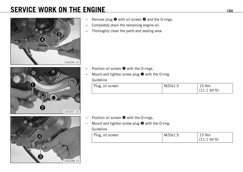
SERVICE WORK ON THE ENGINE 154
100206-10
– Remove plug with oil screen and the O-rings.
– Completely drain the remaining engine oil.
– Thoroughly clean the parts and sealing area.
100207-10
– Position oil screen with the O-rings.
– Mount and tighten screw plug with the O-ring.
Guideline
Plug, oil screen M20x1.5 15 Nm(11.1 lbf ft)
100208-10
– Position oil screen with the O-rings.
– Mount and tighten screw plug with the O-ring.
Guideline
Plug, oil screen M20x1.5 15 Nm(11.1 lbf ft)

SERVICE WORK ON THE ENGINE 155
16.6Installing the oil filterx
100204-10
– Insert oil filters and .
– Oil the O-rings of the oil filter covers. Mount oil filter covers and .
– Mount and tighten the screws.
Guideline
Screw, oil filter cover M5 6 Nm (4.4 lbf ft)
16.7Filling up with engine oilx
InfoToo little engine oil or poor-quality engine oil results in premature wear to the engine.
100209-10
– Remove filler plug with O-ring from the clutch cover and add engine oil.
Engine oil 1.70 l (1.8 qt.) Engine oil (SAE 10W/60)(00062010035) ( p. 186)
Alternative engineoil
Engine oil(SAE 10W/50)( p. 186)
– Refit plug with O-ring and tighten it.
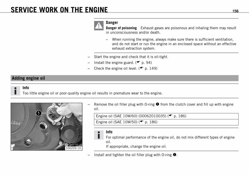
SERVICE WORK ON THE ENGINE 156
DangerDanger of poisoning Exhaust gases are poisonous and inhaling them may resultin unconsciousness and/or death.
– When running the engine, always make sure there is sufficient ventilation,and do not start or run the engine in an enclosed space without an effectiveexhaust extraction system.
– Start the engine and check that it is oil-tight.
– Install the engine guard. ( p. 94)
– Check the engine oil level. ( p. 149)
16.8Adding engine oil
InfoToo little engine oil or poor-quality engine oil results in premature wear to the engine.
100209-10
– Remove the oil filler plug with O-ring from the clutch cover and fill up with engineoil.
Engine oil (SAE 10W/60) (00062010035) ( p. 186)
Engine oil (SAE 10W/50) ( p. 186)
InfoFor optimal performance of the engine oil, do not mix different types of engineoil.If appropriate, change the engine oil.
– Install and tighten the oil filler plug with O-ring .

SERVICE WORK ON THE ENGINE 157
DangerDanger of poisoning Exhaust gases are poisonous and inhaling them may resultin unconsciousness and/or death.
– When running the engine, always make sure there is sufficient ventilation,and do not start or run the engine in an enclosed space without an effectiveexhaust extraction system.
– Start the engine and check that it is oil-tight.
– Check the engine oil level. ( p. 149)

CLEANING, CARE 158
17.1Cleaning the motorcycle
NoteMaterial damage Damage and destruction of components by high-pressure cleaning equipment.
– Never clean the vehicle with high-pressure cleaning equipment or a strong water-jet. The excessive pressure can penetrate electricalcomponents, socket connects, throttle cables, and bearings, etc., and can damage or destroy these parts.
WarningEnvironmental hazard Hazardous substances cause environmental damage.
– Oil, grease, filters, fuel, cleaners, brake fluid, etc., should be disposed of as stipulated in applicable regulations.
InfoIf you clean the motorcycle regularly, its value and appearance will be maintained over a long period.Avoid direct sunshine on the motorcycle during cleaning.
401061-01
– Seal the exhaust system to keep water out.
– First remove coarse dirt particles with a gentle spray of water.
– Spray very dirty areas with a normal motorcycle cleaner and then clean with a brush.
Motorcycle cleaner ( p. 190)
InfoClean the vehicle using a soft sponge and warm water containing normal motor-cycle cleaner.If the vehicle was operated in road salt, clean it with cold water. Warm waterenhances the corrosive effects of salt.
– After rinsing the motorcycle with a gentle spray of water, allow it to dry thoroughly.

CLEANING, CARE 159
WarningDanger of accidents Reduced braking efficiency due to wet or dirty brakes.
– Clean or dry dirty or wet brakes by riding and braking gently.
– After cleaning, ride the vehicle a short distance until the engine is warm, applying thebrakes occasionally.
InfoThe heat produced causes water at inaccessible locations in the engine and thebrakes to evaporate.
– Push back the protection covers of the handlebar controls to allow any water that haspenetrated to evaporate.
– After the motorcycle has cooled off, lubricate all moving parts and bearings.
– Clean the chain. ( p. 81)
– Treat bare metal parts (except for brake discs and exhaust system) with anti-corrosionmaterials.
Cleaning and preserving materials for metal, rubber and plastic ( p. 189)
– Treat all painted parts with a mild paint polish.
High-luster polish for paint ( p. 189)
– Treat all plastic parts and powder-coated parts with a mild cleaning and care agent.
Paint cleaner and polish for high-gloss and matte finishes, bare metal and plasticsurfaces ( p. 190)
– Oil the ignition/steering lock.
Universal oil spray ( p. 190)

CLEANING, CARE 160
17.2Protective treatment for winter operation
InfoIf you use the motorcycle in winter, you must expect salt on the roads. You should therefore take precautions against aggressiveroad salt.If the vehicle was operated in road salt, clean it with cold water. Warm water enhances the corrosive effects of salt.
401060-01
– Clean the motorcycle. ( p. 158)
– Treat the engine, the swingarm, and all other bare or galvanized parts (except brakediscs) with a wax-based anti-corrosion substance.
InfoTo prevent serious reduction of the braking efficiency, make sure noanti-corrosion substance gets on to the brake discs.After use on salted roads, clean the motorcycle thoroughly with cold water anddry it properly.
– Clean the chain. ( p. 81)

STORAGE 161
18.1Storage
InfoIf you want to garage the motorcycle for a longer period, take the following actions.Before storing the motorcycle, check all parts for function and wear. If service, repairs, or replacements are necessary, you shoulddo this during the storage period (less workshop overload). In this way, you can avoid long workshop waiting times at the start of thenew season.
401058-01
– Make sure the tank is as empty as possible so that you can fill up with fresh fuel whenyou put the motorcycle back into operation.
– Clean the motorcycle. ( p. 158)
– Change the engine oil and filter, clean the oil screens.x ( p. 150)
– Check the antifreeze and coolant level. ( p. 139)
– Check the tire air pressure. ( p. 120)
– Remove the battery.x ( p. 123)
– Recharge the battery.x ( p. 124)
Guideline
Storage temperature of battery withoutdirect sunshine
0… 35 °C (32… 95 °F)
– Store the vehicle in a dry location that is not subject to large fluctuations in tempera-ture.
InfoKTM recommends jacking up the motorcycle.
– Raise the motorcycle with the lift stand. ( p. 73)
– Cover the motorcycle with a tarp or similar cover that is permeable to air.

STORAGE 162
InfoDo not use non-porous materials since they prevent humidity from escaping,thus causing corrosion.Avoid running the engine for a short time only. Since the engine cannot warmup properly, the water vapor produced during combustion condenses and causesvalves and exhaust system to rust.
18.2Preparing for use after storage
401059-01
– Remove the motorcycle from the lift stand. ( p. 73)
– Recharge the battery.x ( p. 124)
– Install the battery.x ( p. 124)
– Set the clock. ( p. 35)
– Refuel. ( p. 56)
– Perform checks and vehicle care when preparing for use. ( p. 48)
– Take a test ride.

TROUBLESHOOTING 163
Faults Possible cause Action
The engine does not turn when thestarter button is pressed
Operating error – Carry out the start procedure. ( p. 49)
Battery is discharged – Recharge the battery.x ( p. 124)
Fuse 1, 2, 3 or 4 is blown – Change the fuses of individual power consumers.( p. 128)
Main fuse burned out – Change the main fuse. ( p. 126)
No ground connection present. – Check the ground connection.
Engine turns only if the clutch lever isdrawn
The vehicle is in gear – Shift gear to neutral.
The vehicle is in gear and the sidestand is folded out
– Shift gear to neutral.
Engine turns but does not start. Operating error – Carry out the start procedure. ( p. 49)
Fuse 4 blown – Change the fuses of individual power consumers.( p. 128)
Coupling of fuel hose connection notconnected
– Reconnect coupling of fuel hose connection.
Socket connector of wiring harness isoxidized
– Clean the socket connector and treat it with con-tact spray.
Defect in fuel injection system – Read out the fault memory using the KTM diag-nostics tool.x
Engine has too little power. Air filter is very dirty – Remove the air filter.x ( p. 79)
– Install the air filter.x ( p. 80)
Fuel filter is very dirty – Check the fuel pressure.xDefect in fuel injection system – Read out the fault memory using the KTM diag-
nostics tool.xEngine overheats. Too little coolant in cooling system – Check the cooling system for leakage.
– Check the coolant level. ( p. 141)

TROUBLESHOOTING 164
Faults Possible cause Action
Engine overheats. Radiator fins very dirty – Clean radiator fins.
Foam formation in cooling system – Drain the coolant.x ( p. 143)
– Fill the cooling system.x ( p. 144)
Buckled or damaged radiator hose – Change the radiator hose.xThermostat is faulty – Check the thermostat.xFuse 5 blown – Change the fuses of individual power consumers.
( p. 128)
Defect in radiator fan system – Check the radiator fan system.xAir in cooling system – Fill the cooling system.x ( p. 144)
FI warning lamp (MIL) lights/flashes Defect in fuel injection system – Read out the fault memory using the KTM diag-nostics tool.x
Engine dies during the journey Lack of fuel – Refuel. ( p. 56)
Fuse 1, 2 or 4 blown – Change the fuses of individual power consumers.( p. 128)
High oil consumption Engine vent hose bent – Route the vent hose without bends or change it ifnecessary.
Engine oil level too high – Check the engine oil level. ( p. 149)
Engine oil too thin (low viscosity) – Change the engine oil and filter, clean the oilscreens.x ( p. 150)
Headlight and parking light not func-tioning
Fuse 7 blown – Change the fuses of individual power consumers.( p. 128)
Turn signal, brake light and horn notfunctioning
Fuse 6 blown – Change the fuses of individual power consumers.( p. 128)

TROUBLESHOOTING 165
Faults Possible cause Action
Time is not (correctly) displayed Fuse 2 blown – Change the fuses of individual power consumers.( p. 128)
– Set the clock. ( p. 35)
Battery discharged Ignition not switched off when vehiclewas parked
– Recharge the battery.x ( p. 124)
Battery is not charged by alternator – Check the charging voltage.x– Check the quiescent current.x
Combination instrument shows nothingin the display
Fuse 1 blown – Change the fuses of individual power consumers.( p. 128)
Speedometer in combination instru-ment not functioning
Speedometer wiring harness is dam-aged or plug-in connection is oxidized
– Check the wiring harness and plug-in connection.

BLINK CODE 166
Blink code FI of warning lamp(MIL)
02 FI warning lamp (MIL) flashes briefly 2x
Error level condition Crankshaft position sensor - circuit fault
Blink code FI of warning lamp(MIL)
06 FI warning lamp (MIL) flashes briefly 6x
Error level condition Throttle position sensor circuit A - input signal too low
Throttle position sensor circuit A - input signal too high
Blink code FI of warning lamp(MIL)
08 FI warning lamp (MIL) flashes briefly 8x
Error level condition Accelerator position sensor - input signal too low
Accelerator position sensor - input signal too high
Blink code FI of warning lamp(MIL)
09 FI warning lamp (MIL) flashes briefly 9x
Error level condition Manifold absolute pressure sensor cylinder 1 - Input signal too low
Manifold absolute pressure sensor cylinder 1 - input signal too high
Blink code FI of warning lamp(MIL)
12 FI warning lamp (MIL) flashes 1x long, 2x short
Error level condition Engine coolant temperature sensor - input signal too low
Engine coolant temperature sensor - input signal too high

BLINK CODE 167
Blink code FI of warning lamp(MIL)
13 FI warning lamp (MIL) flashes 1x long, 3x short
Error level condition Intake air temperature sensor - input signal too low
Intake air temperature sensor - input signal too high
Blink code FI of warning lamp(MIL)
14 FI warning lamp (MIL) flashes 1x long, 4x short
Error level condition Ambient air pressure sensor - input signal too low
Ambient air pressure sensor - input signal too high
Blink code FI of warning lamp(MIL)
15 FI warning lamp (MIL) flashes 1x long, 5x short
Error level condition Rollover sensor - input signal too low
Rollover sensor - input signal too high
Blink code FI of warning lamp(MIL)
17 FI warning lamp (MIL) flashes 1x long, 7x short
Error level condition Lambda sensor cylinder 1, sensor 1 - circuit fault
Blink code FI of warning lamp(MIL)
24 FI warning lamp (MIL) flashes 2x long, 4x short
Error level condition System voltage - circuit fault

BLINK CODE 168
Blink code FI of warning lamp(MIL)
25 FI warning lamp (MIL) flashes 2x long, 5x short
Error level condition Side stand switch - circuit fault
Blink code FI of warning lamp(MIL)
26 FI warning lamp (MIL) flashes 2x long, 6x short
Error level condition Motor drive hall sensor - circuit fault
Blink code FI of warning lamp(MIL)
37 FI warning lamp (MIL) flashes 3x long, 7x short
Error level condition Ignition coil cylinder 1 - circuit fault
Blink code FI of warning lamp(MIL)
41 FI warning lamp (MIL) flashes 4x long, 1x short
Error level condition Fuel pump controller - short circuit to ground or open circuit
Fuel pump controller - input signal too high
Blink code FI of warning lamp(MIL)
45 FI warning lamp (MIL) flashes 4x long, 5x short
Error level condition Lambda sensor heater cylinder 1, sensor 1 - short circuit to ground or open circuit
Lambda sensor heater cylinder 1, sensor 1 - input signal too high
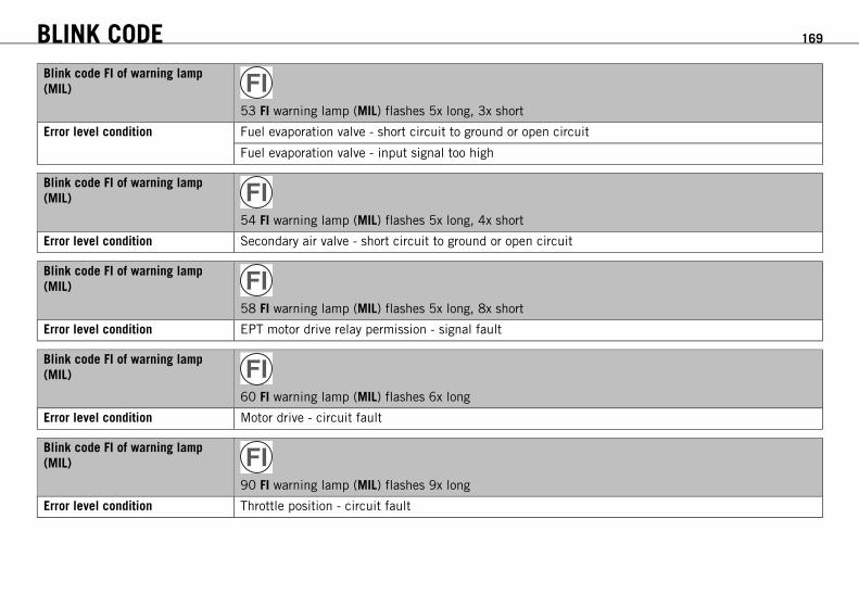
BLINK CODE 169
Blink code FI of warning lamp(MIL)
53 FI warning lamp (MIL) flashes 5x long, 3x short
Error level condition Fuel evaporation valve - short circuit to ground or open circuit
Fuel evaporation valve - input signal too high
Blink code FI of warning lamp(MIL)
54 FI warning lamp (MIL) flashes 5x long, 4x short
Error level condition Secondary air valve - short circuit to ground or open circuit
Blink code FI of warning lamp(MIL)
58 FI warning lamp (MIL) flashes 5x long, 8x short
Error level condition EPT motor drive relay permission - signal fault
Blink code FI of warning lamp(MIL)
60 FI warning lamp (MIL) flashes 6x long
Error level condition Motor drive - circuit fault
Blink code FI of warning lamp(MIL)
90 FI warning lamp (MIL) flashes 9x long
Error level condition Throttle position - circuit fault

BLINK CODE 170
Blink code FI of warning lamp(MIL)
91 FI warning lamp (MIL) flashes 9x long, 1x short
Error level condition CAN bus communication error
Blink code FI of warning lamp(MIL)
92 FI warning lamp (MIL) flashes 9x long, 2x short
Error level condition Motor drive voltage (internal) - circuit fault

TECHNICAL DATA - ENGINE 171
Design 1-cylinder 4-stroke engine, water-cooled
Displacement 654 cm³ (39.91 cu in)
Stroke 80 mm (3.15 in)
Bore 102 mm (4.02 in)
Compression ratio 11.8:1
Idle speed
Coolant temperature: ≥ 70 °C (≥ 158 °F) 1,550… 1,650 rpm
Control OHC, 4 valves controlled via rocker arm, chain drive
Valve diameter, intake 40 mm (1.57 in)
Valve diameter, exhaust 34 mm (1.34 in)
Valve play, cold 0.07… 0.13 mm (0.0028… 0.0051 in)
Crankshaft bearing 2 roller bearings
Conrod bearing Needle bearing
Piston pin bearing Bronze bush
Pistons Forged light alloy
Piston rings 1 L-ring, 1 tapered compression piston ring, 1 oil scraper ring
Engine lubrication Semi-dry sump lubrication with two rotor pumps
Primary transmission 36:79
Clutch APTC™ Antihopping clutch in oil bath / hydraulically operated
Gearbox 6-gears, claw-shifted
Transmission ratio
1st gear 14:35
2nd gear 16:28
3rd gear 21:28
4th gear 21:23

TECHNICAL DATA - ENGINE 172
5th gear 23:22
6th gear 23:20
Mixture preparation Electronic fuel injection
Ignition Contactless controlled fully electronic ignition with digital ignitionadjustment
Alternator 12 V, 224 W
Spark plug NGK LKAR 8AI - 9
Spark plug electrode gap 0.9 mm (0.035 in)
Cooling Water cooling, permanent circulation of coolant by water pump
Starting aid Electric starter, automatic decompressor
21.1Capacity - engine oil
Engine oil 1.70 l (1.8 qt.) Engine oil (SAE 10W/60) (00062010035) ( p. 186)
Alternative engine oil Engine oil (SAE 10W/50)( p. 186)
21.2Capacity - coolant
Coolant 1.20 l (1.27 qt.) Coolant ( p. 185)
Coolant (mixed ready to use) ( p. 185)

TECHNICAL DATA - ENGINE TIGHTENING TORQUES 173
Oil hole plug self-tapping 9 Nm (6.6 lbf ft) Loctite® 243™
Screw, membrane fixation M3 2.5 Nm (1.84 lbf ft) Loctite® 243™
Hose clamp, intake flange M4 1.5 Nm (1.11 lbf ft) –
Oil jet, conrod lubrication M4 2 Nm (1.5 lbf ft) Loctite® 243™
Locking screw for bearing M5 6 Nm (4.4 lbf ft) Loctite® 243™
Screw, breather cover on valve cover M5 3 Nm (2.2 lbf ft) Loctite® 243™
Screw, clutch spring M5 6 Nm (4.4 lbf ft) –
Screw, cover plate for oil return line M5 6 Nm (4.4 lbf ft) –
Screw, gear sensor M5 5 Nm (3.7 lbf ft) Loctite® 243™
Screw, oil filter cover M5 6 Nm (4.4 lbf ft) –
Screw, oil pump cover M5 6 Nm (4.4 lbf ft) Loctite® 243™
Plug, vacuum connection M6 10 Nm (7.4 lbf ft) Loctite® 243™
Screw in alternator cover M6 10 Nm (7.4 lbf ft) –
Screw, alternator cover (chain shaftthrough-hole)
M6 10 Nm (7.4 lbf ft) Loctite® 243™
Screw, autodecompression M6 3… 4 Nm (2.2… 3 lbf ft) Loctite® 243™
Screw, axial lock of camshaft M6 10 Nm (7.4 lbf ft) Loctite® 243™
Screw, clutch cover M6 10 Nm (7.4 lbf ft) –
Screw, clutch slave cylinder M6x20 10 Nm (7.4 lbf ft) Loctite® 243™
Screw, clutch slave cylinder M6x35 10 Nm (7.4 lbf ft) –
Screw, cylinder M6 10 Nm (7.4 lbf ft) Loctite® 243™
Screw, cylinder head M6 10 Nm (7.4 lbf ft) Loctite® 243™
Screw, engine case M6 10 Nm (7.4 lbf ft) –
Screw, ignition pulse generator M6 10 Nm (7.4 lbf ft) Loctite® 243™

TECHNICAL DATA - ENGINE TIGHTENING TORQUES 174
Screw, locking lever M6 10 Nm (7.4 lbf ft) Loctite® 243™
Screw, rocker arm shaft M6 12 Nm (8.9 lbf ft) –
Screw, shift drum locating M6 10 Nm (7.4 lbf ft) Loctite® 243™
Screw, shift lever M6 10 Nm (7.4 lbf ft) Loctite® 222
Screw, starter motor M6 10 Nm (7.4 lbf ft) Loctite® 243™
Screw, stator bracket M6 10 Nm (7.4 lbf ft) Loctite® 243™
Screw, thermostat housing M6 10 Nm (7.4 lbf ft) Loctite® 243™
Screw, timing chain guide rail M6 10 Nm (7.4 lbf ft) Loctite® 243™
Screw, timing chain tensioning rail M6 10 Nm (7.4 lbf ft) Loctite® 243™
Screw, valve cover M6 10 Nm (7.4 lbf ft) –
Screw, water pump cover M6 10 Nm (7.4 lbf ft) –
Screw, water pump wheel M6 10 Nm (7.4 lbf ft) Loctite® 243™
Oil jet, piston cooling M6x0.75 4 Nm (3 lbf ft) Loctite® 243™
Plug, crankshaft location M8 20 Nm (14.8 lbf ft) –
Stud, exhaust flange M8 10 Nm (7.4 lbf ft) Loctite® 243™
Cylinder head screw M10 Tightening sequence:Tighten diagonally, beginningwith the rear screw on thechain shaft.Step 115 Nm (11.1 lbf ft)Step 230 Nm (22.1 lbf ft)Step 345 Nm (33.2 lbf ft)Step 460 Nm (44.3 lbf ft)
Lubricated with engine oil

TECHNICAL DATA - ENGINE TIGHTENING TORQUES 175
Oil hole plug M10x1 15 Nm (11.1 lbf ft) Loctite® 243™
Plug, drain hole of water pump M10x1 15 Nm (11.1 lbf ft) –
Plug, oil bore for oil radiator M10x1 15 Nm (11.1 lbf ft) –
Screw, unlocking of timing chain ten-sioner
M10x1 10 Nm (7.4 lbf ft) –
Spark plug M12x1.25 17 Nm (12.5 lbf ft) –
Coolant temperature sensor on cylinderhead
M12x1.5 12 Nm (8.9 lbf ft) –
Oil drain plug with magnet M12x1.5 20 Nm (14.8 lbf ft) –
Oil pressure regulator valve plug M12x1.5 20 Nm (14.8 lbf ft) –
Plug, oil bore M14x1.5 15 Nm (11.1 lbf ft) Loctite® 243™
Engine case stud M16x1.5 25 Nm (18.4 lbf ft) Loctite® 243™
Rotor nut M18x1.5 100 Nm (73.8 lbf ft) –
Nut, engine sprocket M20x1.5 60 Nm (44.3 lbf ft) Loctite® 243™
Nut, inner clutch hub M20x1.5 100 Nm (73.8 lbf ft) Loctite® 243™
Nut, primary gear M20LHx1.5 90 Nm (66.4 lbf ft) Loctite® 243™
Plug, oil screen M20x1.5 15 Nm (11.1 lbf ft) –
Plug, timing chain tensioner M20x1.5 25 Nm (18.4 lbf ft) –
Plug, oil thermostat M24x1.5 15 Nm (11.1 lbf ft) –
Screw in alternator cover M24x1.5 8 Nm (5.9 lbf ft) –

TECHNICAL DATA - CHASSIS 176
Frame Lattice frame made of chrome molybdenum steel tubing, powder-coated
Fork WP Suspension 4860 MXMA
Shock absorber WP Suspension 4618 with Pro‑Lever deflector
Suspension travel
Front 275 mm (10.83 in)
Rear 275 mm (10.83 in)
Brake system
Front Disc brake with dual-piston brake caliper, floating
Rear Disc brake with single-piston brake caliper, floating
Brake discs - diameter
Front 300 mm (11.81 in)
Rear 240 mm (9.45 in)
Brake discs - wear limit
Front 4.5 mm (0.177 in)
Rear 3.5 mm (0.138 in)
Tire air pressure, road, solo
Front 1.8 bar (26 psi)
Rear 1.8 bar (26 psi)
Tire air pressure with passenger / fully loaded
Front 2.0 bar (29 psi)
Rear 2.2 bar (32 psi)
Tire air pressure, offroad, single rider
Front 1.5 bar (22 psi)
Rear 1.5 bar (22 psi)

TECHNICAL DATA - CHASSIS 177
Secondary drive ratio 15:45
Chain 5/8 x 1/4” X‑ring
Steering head angle 63°
Wheelbase 1,504±15 mm (59.21±0.59 in)
Seat height unloaded 930 mm (36.61 in)
Ground clearance unloaded 320 mm (12.6 in)
Weight without fuel approx. 138.5 kg (305.3 lb.)
Maximum permissible front axle load 150 kg (331 lb.)
Maximum permissible rear axle load 200 kg (441 lb.)
Maximum permissible overall weight 350 kg (772 lb.)
Battery YTZ10S Battery voltage: 12 VNominal capacity: 8.6 Ahmaintenance-free
Fuse 58011109130 30 A
Fuse 75011088015 15 A
Fuse 75011088010 10 A
23.1Lighting equipment
Headlight S2 / socket BA20d 12 V30/35 W
Parking light W5W / socket W2.1x9.5d 12 V5 W
Instrument lights and indicator lamps LED
Turn signal RY10W / socket BAU15s 12 V10 W

TECHNICAL DATA - CHASSIS 178
Brake/tail light P21/5W / socket BAY15d 12 V21/5 W
23.2Tires
Front tire Rear tire
90/90 - 21 M/C 54R TTPirelli MT 21 RALLYCROSS
140/80 - 18 M/C 70R TTPirelli MT 21 RALLYCROSS
Additional information is available in the Service section under:http://www.ktm.com
23.3Capacity - fuel
Total fuel tank capacity, approx. 12 l (3.2 US gal) Super unleaded (ROZ 95 / RON 95 / PON 91) ( p. 188)
Fuel reserve, approx. 2.5 l (2.6 qt.)

TECHNICAL DATA - FORK 179
Fork part number 14.18.7K.41
Fork WP Suspension 4860 MXMA
Compression damping
Comfort 20 clicks
Standard 15 clicks
Sport 10 clicks
Full payload 10 clicks
Rebound damping
Comfort 20 clicks
Standard 15 clicks
Sport 10 clicks
Full payload 10 clicks
Spring length with preload spacer(s) 495 mm (19.49 in)
Spring rate
Soft 5.0 N/mm (28.6 lb/in)
Medium (standard) 5.2 N/mm (29.7 lb/in)
Hard 5.4 N/mm (30.8 lb/in)
Air chamber length 100+0−20 mm (3.94+0
−0.79 in)
Fork length 915 mm (36.02 in)
Fork oil per fork leg 635 ml (21.47 fl. oz.) Fork oil (SAE 5) ( p. 187)

TECHNICAL DATA - SHOCK ABSORBER 180
Shock absorber part number 15.18.7E.41
Shock absorber WP Suspension 4618 with Pro‑Lever deflector
Compression damping, high-speed
Comfort 2 turns
Standard 1.5 turns
Sport 1 turn
Full payload 1 turn
Compression damping, low-speed
Comfort 20 clicks
Standard 15 clicks
Sport 10 clicks
Full payload 10 clicks
Rebound damping
Comfort 20 clicks
Standard 15 clicks
Sport 10 clicks
Full payload 10 clicks
Spring preload 20 mm (0.79 in)
Spring rate
Soft 75 N/mm (428 lb/in)
Medium (standard) 80 N/mm (457 lb/in)
Hard 85 N/mm (485 lb/in)
Spring length 220 mm (8.66 in)
Gas pressure 10 bar (145 psi)
Static sag 25 mm (0.98 in)

TECHNICAL DATA - SHOCK ABSORBER 181
Riding sag 70… 80 mm (2.76… 3.15 in)
Fitted length 405 mm (15.94 in)
Shock absorber oil ( p. 187) SAE 2,5

TECHNICAL DATA - CHASSIS TIGHTENING TORQUES 182
Screw, license plate holder, bottom EJOT 3 Nm (2.2 lbf ft) –
Screw, side stand switch EJOT 2 Nm (1.5 lbf ft) –
Screw, SLS valve EJOT 2 Nm (1.5 lbf ft) –
Spoke nipple, front wheel M4.5 4 Nm (3 lbf ft) –
Bolt, foot brake lever stub M5 6 Nm (4.4 lbf ft) Loctite® 243™
Remaining screws, chassis M5 5 Nm (3.7 lbf ft) –
Screw, electrical holder M5 3 Nm (2.2 lbf ft) –
Screw, exhaust heat shield M5 6 Nm (4.4 lbf ft) Loctite® 243™
Screw, fuel level sensor M5 3 Nm (2.2 lbf ft) –
Screw, fuel pump M5 6 Nm (4.4 lbf ft) –
Screw, headlight mask M5 5 Nm (3.7 lbf ft) –
Screw, starter cable on starter M5 3 Nm (2.2 lbf ft) –
Spoke nipple, rear wheel M5 4 Nm (3 lbf ft) –
Nut, foot brake cylinder screw M6 10 Nm (7.4 lbf ft) –
Remaining nuts, chassis M6 15 Nm (11.1 lbf ft) –
Remaining screws on fuel tank M6 5 Nm (3.7 lbf ft) –
Remaining screws, chassis M6 10 Nm (7.4 lbf ft) –
Screw, air filter box top M6 2 Nm (1.5 lbf ft) –
Screw, ball joint of push rod on footbrake cylinder
M6 10 Nm (7.4 lbf ft) Loctite® 243™
Screw, brake fluid reservoir of rear brake M6 5 Nm (3.7 lbf ft) –
Screw, chain sliding guard M6 6 Nm (4.4 lbf ft) Loctite® 243™
Screw, front brake disc M6 14 Nm (10.3 lbf ft) Loctite® 243™
Screw, ignition lock M6 10 Nm (7.4 lbf ft) Loctite® 243™
Screw, lower radiator bracket M6 8 Nm (5.9 lbf ft) –

TECHNICAL DATA - CHASSIS TIGHTENING TORQUES 183
Screw, magnetic holder on side stand M6 12 Nm (8.9 lbf ft) Loctite® 243™
Screw, rear brake disc M6 14 Nm (10.3 lbf ft) Loctite® 243™
Screw, seat lock M6 5 Nm (3.7 lbf ft) Loctite® 222
Screw, side cover M6 5 Nm (3.7 lbf ft) –
Screw, upper radiator bracket M6 12 Nm (8.9 lbf ft) –
Screw, voltage regulator M6 8 Nm (5.9 lbf ft) –
Nut, manifold on cylinder head M8 25 Nm (18.4 lbf ft) Copper paste
Nut, rear sprocket screw M8 35 Nm (25.8 lbf ft) Loctite® 243™
Remaining nuts, chassis M8 30 Nm (22.1 lbf ft) –
Remaining screws, chassis M8 25 Nm (18.4 lbf ft) –
Screw, bottom triple clamp M8 12 Nm (8.9 lbf ft) –
Screw, chain sliding piece M8 15 Nm (11.1 lbf ft) –
Screw, connection lever on frame M8 30 Nm (22.1 lbf ft) Loctite® 243™
Screw, exhaust clamp on main silencer M8 25 Nm (18.4 lbf ft) –
Screw, foot brake lever M8 28 Nm (20.7 lbf ft) Loctite® 243™
Screw, fork stub M8 15 Nm (11.1 lbf ft) –
Screw, front brake caliper M8 25 Nm (18.4 lbf ft) Loctite® 243™
Screw, front footrest bracket M8 25 Nm (18.4 lbf ft) –
Screw, fuel tank, bottom M8 28 Nm (20.7 lbf ft) Loctite® 243™
Screw, fuel tank, top M8 28 Nm (20.7 lbf ft) Loctite® 243™
Screw, handlebar clamp M8 20 Nm (14.8 lbf ft) –
Screw, handrail M8 20 Nm (14.8 lbf ft) –
Screw, license plate holder, top M8 20 Nm (14.8 lbf ft) –
Screw, main silencer holder M8 25 Nm (18.4 lbf ft) –

TECHNICAL DATA - CHASSIS TIGHTENING TORQUES 184
Screw, main silencer holder on fuel tank M8 25 Nm (18.4 lbf ft) –
Screw, rear footrest bracket M8x16 25 Nm (18.4 lbf ft) –
Screw, side stand bracket M8 28 Nm (20.7 lbf ft) Loctite® 243™
Screw, spring holder on side standbracket
M8 25 Nm (18.4 lbf ft) Loctite® 243™
Screw, steering stem M8 20 Nm (14.8 lbf ft) Loctite® 243™
Screw, top triple clamp M8 17 Nm (12.5 lbf ft) –
Engine carrying screw M10 45 Nm (33.2 lbf ft) Loctite® 243™
Remaining nuts, chassis M10 50 Nm (36.9 lbf ft) –
Remaining screws, chassis M10 45 Nm (33.2 lbf ft) –
Screw, bottom shock absorber M10 45 Nm (33.2 lbf ft) Loctite® 243™
Screw, engine bearer on frame M10 45 Nm (33.2 lbf ft) –
Screw, handlebar support M10 40 Nm (29.5 lbf ft) –
Screw, side stand M10 35 Nm (25.8 lbf ft) Loctite® 243™
Screw, top shock absorber M10 45 Nm (33.2 lbf ft) Loctite® 243™
Screw, swingarm pivot M12 80 Nm (59 lbf ft) –
Lambda sensor M12x1.25 25 Nm (18.4 lbf ft) Copper paste
Nut, linkage lever on swingarm M14x1.5 100 Nm (73.8 lbf ft) –
Nut, linkage lever to rocker arm M14x1.5 100 Nm (73.8 lbf ft) –
Screw, bottom steering head M20x1.5 60 Nm (44.3 lbf ft) Loctite® 243™
Screw, top steering head M20x1.5 12 Nm (8.9 lbf ft) –
Screw, front wheel spindle M24x1.5 40 Nm (29.5 lbf ft) –
Nut, rear wheel spindle M25x1.5 90 Nm (66.4 lbf ft) –

SUBSTANCES 185
Brake fluid DOT 4 / DOT 5.1According to– DOT
Guideline– Use only brake fluid that complies with the specified standard (see specifications on the container) and that possesses the correspond-
ing properties. KTM recommends Castrol and Motorex® products.
SupplierCastrol– RESPONSE BRAKE FLUID SUPER DOT 4
Motorex®
– Brake Fluid DOT 5.1
CoolantGuideline– Use only suitable coolant (also in countries with high temperatures). Use of low-quality antifreeze can lead to corrosion and foaming.
KTM recommends Motorex® products.
Mixture ratio
Antifreeze protection: −25… −45 °C (−13…−49 °F)
50 % corrosion inhibitor/antifreeze50 % distilled water
Coolant (mixed ready to use)
Antifreeze −40 °C (−40 °F)
SupplierMotorex®
– Anti Freeze

SUBSTANCES 186
Engine oil (SAE 10W/60) (00062010035)According to– JASO T903 MA ( p. 191)
– SAE ( p. 191) (SAE 10W/60)
– KTM LC4 2007+
Guideline– Use only engine oils that comply with the specified standards (see specifications on the container) and that possess the corresponding
properties. KTM recommends Motorex® products.
Synthetic engine oil
SupplierMotorex®
– Motorex® KTM Cross Power 4T
Engine oil (SAE 10W/50)According to– JASO T903 MA ( p. 191)
– SAE ( p. 191) (SAE 10W/50)
Guideline– Use only engine oils that comply with the specified standards (see specifications on the container) and that possess the corresponding
properties. KTM recommends Motorex® products.
Fully synthetic engine oil
SupplierMotorex®
– Power Synt 4T

SUBSTANCES 187
Fork oil (SAE 5)According to– SAE ( p. 191) (SAE 5)
Guideline– Use only oils that comply with the specified standards (see specifications on the container) and that possess the corresponding proper-
ties. KTM recommends Motorex® products.
SupplierMotorex®
– Racing Fork Oil
Hydraulic fluid (15)According to– ISO VG (15)
Guideline– Use only hydraulic oil that complies with the specified standard (see specifications on the container) and that possesses the corre-
sponding properties. KTM recommends Motorex® products.
SupplierMotorex®
– Hydraulic Fluid 75
Shock absorber oil (SAE 2,5) (50180342S1)According to– SAE ( p. 191) (SAE 2,5)
Guideline– Use only oils that comply with the specified standards (see specifications on the container) and that possess the corresponding proper-
ties.

SUBSTANCES 188
Super unleaded (ROZ 95 / RON 95 / PON 91)According to– DIN EN 228 (ROZ 95 / RON 95 / PON 91)

AUXILIARY SUBSTANCES 189
Chain cleanerGuideline– KTM recommends Motorex® products.
SupplierMotorex®
– Chain Clean
Cleaning and preserving materials for metal, rubber and plasticGuideline– KTM recommends Motorex® products.
SupplierMotorex®
– Protect & Shine
High-luster polish for paintGuideline– KTM recommends Motorex® products.
SupplierMotorex®
– Moto Polish
Long-life greaseGuideline– KTM recommends Motorex® products.
SupplierMotorex®
– Bike Grease 2000

AUXILIARY SUBSTANCES 190
Motorcycle cleanerGuideline– KTM recommends Motorex® products.
SupplierMotorex®
– Moto Clean 900
Off-road chain sprayGuideline– KTM recommends Motorex® products.
SupplierMotorex®
– Chainlube Offroad
Paint cleaner and polish for high-gloss and matte finishes, bare metal and plastic surfacesGuideline– KTM recommends Motorex® products.
SupplierMotorex®
– Clean & Polish
Universal oil sprayGuideline– KTM recommends Motorex® products.
SupplierMotorex®
– Joker 440 Synthetic
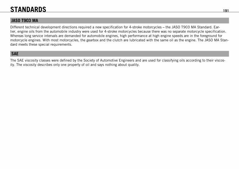
STANDARDS 191
JASO T903 MADifferent technical development directions required a new specification for 4-stroke motorcycles – the JASO T903 MA Standard. Ear-lier, engine oils from the automobile industry were used for 4-stroke motorcycles because there was no separate motorcycle specification.Whereas long service intervals are demanded for automobile engines, high performance at high engine speeds are in the foreground formotorcycle engines. With most motorcycles, the gearbox and the clutch are lubricated with the same oil as the engine. The JASO MA Stan-dard meets these special requirements.
SAEThe SAE viscosity classes were defined by the Society of Automotive Engineers and are used for classifying oils according to their viscos-ity. The viscosity describes only one property of oil and says nothing about quality.

INDEX 192
INDEX
A
Accessories . . . . . . . . . . . . . . . . . . . . . . . . . . . . . . . . . . . . . 9
Air filterinstalling . . . . . . . . . . . . . . . . . . . . . . . . . . . . . . . . . . . 80removing . . . . . . . . . . . . . . . . . . . . . . . . . . . . . . . . . . . 79
Antifreezechecking . . . . . . . . . . . . . . . . . . . . . . . . . . . . . . . . . . 139
B
Baggage . . . . . . . . . . . . . . . . . . . . . . . . . . . . . . . . . . . . . . 46
Batteryfitting . . . . . . . . . . . . . . . . . . . . . . . . . . . . . . . . . . . . 124recharging . . . . . . . . . . . . . . . . . . . . . . . . . . . . . . . . . 124removing . . . . . . . . . . . . . . . . . . . . . . . . . . . . . . . . . . 123
Blink code . . . . . . . . . . . . . . . . . . . . . . . . . . . . . . . . 166-170
Brake discschecking . . . . . . . . . . . . . . . . . . . . . . . . . . . . . . . . . . . 96
Brake fluidfront brake, adding . . . . . . . . . . . . . . . . . . . . . . . . . . . . 98rear brake, adding . . . . . . . . . . . . . . . . . . . . . . . . . . . 106
Brake fluid levelfront brake, checking . . . . . . . . . . . . . . . . . . . . . . . . . . 97rear brake, checking . . . . . . . . . . . . . . . . . . . . . . . . . . 105
Brake liningsfront brake, changing . . . . . . . . . . . . . . . . . . . . . . . . . 100front brake, checking . . . . . . . . . . . . . . . . . . . . . . . . . . 99rear brake, changing . . . . . . . . . . . . . . . . . . . . . . . . . . 108
rear brake, checking . . . . . . . . . . . . . . . . . . . . . . . . . . 108
Brakes . . . . . . . . . . . . . . . . . . . . . . . . . . . . . . . . 54, 95-111Braking . . . . . . . . . . . . . . . . . . . . . . . . . . . . . . . . . . . . . . 54
C
Care . . . . . . . . . . . . . . . . . . . . . . . . . . . . . . . . . . . . 158-160
Chainchecking . . . . . . . . . . . . . . . . . . . . . . . . . . . . . . . . . . . 86cleaning . . . . . . . . . . . . . . . . . . . . . . . . . . . . . . . . . . . 81dirt, checking for . . . . . . . . . . . . . . . . . . . . . . . . . . . . . 81
Chain guideadjusting . . . . . . . . . . . . . . . . . . . . . . . . . . . . . . . . . . . 91checking . . . . . . . . . . . . . . . . . . . . . . . . . . . . . . . . . . . 86
Chain tensionadjusting . . . . . . . . . . . . . . . . . . . . . . . . . . . . . . . . . . . 84checking . . . . . . . . . . . . . . . . . . . . . . . . . . . . . . . . . . . 83
Chassis number . . . . . . . . . . . . . . . . . . . . . . . . . . . . . . . . . 24Cleaning . . . . . . . . . . . . . . . . . . . . . . . . . . . . . . . . . 158-160
Clutchchecking/correcting fluid level . . . . . . . . . . . . . . . . . . . . 92
Clutch lever . . . . . . . . . . . . . . . . . . . . . . . . . . . . . . . . . . . 27basic position, adjusting . . . . . . . . . . . . . . . . . . . . . . . . 92
Combination instrument . . . . . . . . . . . . . . . . . . . . . . . . . . . 31clock, setting . . . . . . . . . . . . . . . . . . . . . . . . . . . . . . . . 35coolant temperature indicator . . . . . . . . . . . . . . . . . . . . . 38display . . . . . . . . . . . . . . . . . . . . . . . . . . . . . . . . . . . . 33display ODO . . . . . . . . . . . . . . . . . . . . . . . . . . . . . . . . . 36
INDEX 193
display TRIP F . . . . . . . . . . . . . . . . . . . . . . . . . . . . . . . . 38function buttons . . . . . . . . . . . . . . . . . . . . . . . . . . . . . . 32indicator lamps . . . . . . . . . . . . . . . . . . . . . . . . . . . . . . 32setting kilometers or miles . . . . . . . . . . . . . . . . . . . . . . . 34speed display . . . . . . . . . . . . . . . . . . . . . . . . . . . . . . . . 34time . . . . . . . . . . . . . . . . . . . . . . . . . . . . . . . . . . . . . . 35TRIP 1 display, setting/resetting . . . . . . . . . . . . . . . . . . . 36TRIP 2 display, setting/resetting . . . . . . . . . . . . . . . . . . . 37
Controls . . . . . . . . . . . . . . . . . . . . . . . . . . . . . . . . . . . 27-43
Coolantdraining . . . . . . . . . . . . . . . . . . . . . . . . . . . . . . . . . . 143
Coolant levelchecking . . . . . . . . . . . . . . . . . . . . . . . . . . . . . . 139, 141
Cooling system . . . . . . . . . . . . . . . . . . . . . . . . . . . . . 139-145filling . . . . . . . . . . . . . . . . . . . . . . . . . . . . . . . . . . . . 144
D
Display . . . . . . . . . . . . . . . . . . . . . . . . . . . . . . . . . . . . . . . 33
E
Electric starter button . . . . . . . . . . . . . . . . . . . . . . . . . . . . . 30Electrical system . . . . . . . . . . . . . . . . . . . . . . . . . . . 123-138Emergency OFF switch . . . . . . . . . . . . . . . . . . . . . . . . . . . . . 30
Enginerunning in . . . . . . . . . . . . . . . . . . . . . . . . . . . . . . . . . . 45
Engine characteristicadjusting . . . . . . . . . . . . . . . . . . . . . . . . . . . . . . . . . . 147
Engine guardinstalling . . . . . . . . . . . . . . . . . . . . . . . . . . . . . . . . . . . 94removing . . . . . . . . . . . . . . . . . . . . . . . . . . . . . . . . . . . 93
Engine number . . . . . . . . . . . . . . . . . . . . . . . . . . . . . . . . . . 25
Engine oiladding . . . . . . . . . . . . . . . . . . . . . . . . . . . . . . . . . . . 156changing . . . . . . . . . . . . . . . . . . . . . . . . . . . . . . . . . . 150draining . . . . . . . . . . . . . . . . . . . . . . . . . . . . . . . . . . 150refilling . . . . . . . . . . . . . . . . . . . . . . . . . . . . . . . . . . . 155
Engine oil levelchecking . . . . . . . . . . . . . . . . . . . . . . . . . . . . . . . . . . 149
Engine sprocketchecking . . . . . . . . . . . . . . . . . . . . . . . . . . . . . . . . . . . 86
Environment . . . . . . . . . . . . . . . . . . . . . . . . . . . . . . . . . . . . 10
F
Filler capclosing . . . . . . . . . . . . . . . . . . . . . . . . . . . . . . . . . . . . 40opening . . . . . . . . . . . . . . . . . . . . . . . . . . . . . . . . . . . . 39
Filling upfuel . . . . . . . . . . . . . . . . . . . . . . . . . . . . . . . . . . . . . . 56
Foot brake lever . . . . . . . . . . . . . . . . . . . . . . . . . . . . . . . . 43basic position, adjusting . . . . . . . . . . . . . . . . . . . . . . . 104free travel, checking . . . . . . . . . . . . . . . . . . . . . . . . . . 104
Fork . . . . . . . . . . . . . . . . . . . . . . . . . . . . . . . . . . . . . . . . 62compression damping, adjusting . . . . . . . . . . . . . . . . . . . 62dust boots, cleaning . . . . . . . . . . . . . . . . . . . . . . . . . . . 74

INDEX 194
fork legs, bleeding . . . . . . . . . . . . . . . . . . . . . . . . . . . . 74rebound, adjusting . . . . . . . . . . . . . . . . . . . . . . . . . . . . 63
Fork part number . . . . . . . . . . . . . . . . . . . . . . . . . . . . . . . . 26
Fork protectorpositioning . . . . . . . . . . . . . . . . . . . . . . . . . . . . . . . . . 76remove . . . . . . . . . . . . . . . . . . . . . . . . . . . . . . . . . . . . 75
Front wheelinstalling . . . . . . . . . . . . . . . . . . . . . . . . . . . . . . . . . . 113removing . . . . . . . . . . . . . . . . . . . . . . . . . . . . . . . . . . 112
Fuel, oils, etc. . . . . . . . . . . . . . . . . . . . . . . . . . . . . . . . . . . . 8
Fuseof individual power consumer, changing . . . . . . . . . . . . . 128
H
Hand brake lever . . . . . . . . . . . . . . . . . . . . . . . . . . . . . . . 27free travel, adjusting . . . . . . . . . . . . . . . . . . . . . . . . . . . 95free travel, checking . . . . . . . . . . . . . . . . . . . . . . . . . . . 95
Handlebar position . . . . . . . . . . . . . . . . . . . . . . . . . . . . . . 71adjusting . . . . . . . . . . . . . . . . . . . . . . . . . . . . . . . . . . . 71
Handrails . . . . . . . . . . . . . . . . . . . . . . . . . . . . . . . . . . . . . 41
Headlightlight range, adjusting . . . . . . . . . . . . . . . . . . . . . . . . . 137
Headlight bulb, changing . . . . . . . . . . . . . . . . . . . . . . . . . . 133
Headlight mask with headlightinstalling . . . . . . . . . . . . . . . . . . . . . . . . . . . . . . . . . . 132removing . . . . . . . . . . . . . . . . . . . . . . . . . . . . . . . . . . 130
Headlight setting, checking . . . . . . . . . . . . . . . . . . . . . . . . . 137
Horn button . . . . . . . . . . . . . . . . . . . . . . . . . . . . . . . . . . . . 29
I
Ignition lock . . . . . . . . . . . . . . . . . . . . . . . . . . . . . . . . . . . 31Indicator lamps . . . . . . . . . . . . . . . . . . . . . . . . . . . . . . . . . 32
K
Key number . . . . . . . . . . . . . . . . . . . . . . . . . . . . . . . . . . . . 25
L
Light switch . . . . . . . . . . . . . . . . . . . . . . . . . . . . . . . . . . . . 28Loading the vehicle . . . . . . . . . . . . . . . . . . . . . . . . . . . . . . . 46
M
Main fusechanging . . . . . . . . . . . . . . . . . . . . . . . . . . . . . . . . . . 126
Motorcyclecleaning . . . . . . . . . . . . . . . . . . . . . . . . . . . . . . . . . . 158raising with lift stand . . . . . . . . . . . . . . . . . . . . . . . . . . 73removing from lift stand . . . . . . . . . . . . . . . . . . . . . . . . 73
O
Oil filterchanging . . . . . . . . . . . . . . . . . . . . . . . . . . . . . . . . . . 150installing . . . . . . . . . . . . . . . . . . . . . . . . . . . . . . . . . . 155removing . . . . . . . . . . . . . . . . . . . . . . . . . . . . . . . . . . 151
Oil screenscleaning . . . . . . . . . . . . . . . . . . . . . . . . . . . . . . 150, 153
Owner's manual . . . . . . . . . . . . . . . . . . . . . . . . . . . . . . . . . 18

INDEX 195
P
Parking . . . . . . . . . . . . . . . . . . . . . . . . . . . . . . . . . . . . . . 55
Parking light bulbchanging . . . . . . . . . . . . . . . . . . . . . . . . . . . . . . . . . . 134
Passenger footrests . . . . . . . . . . . . . . . . . . . . . . . . . . . . . . . 41
Play in throttle cableadjusting . . . . . . . . . . . . . . . . . . . . . . . . . . . . . . . . . . 147checking . . . . . . . . . . . . . . . . . . . . . . . . . . . . . . . . . . 146
Preparing for useafter storage . . . . . . . . . . . . . . . . . . . . . . . . . . . . . . . 162checks and vehicle care when preparing for use . . . . . . . . 48
Protective treatment for winter operation . . . . . . . . . . . . . . . . 160
Putting into operationadvice on first use . . . . . . . . . . . . . . . . . . . . . . . . . . . . 44
R
Rear hub rubber damperschecking . . . . . . . . . . . . . . . . . . . . . . . . . . . . . . . . . . 117
Rear sprocketchecking . . . . . . . . . . . . . . . . . . . . . . . . . . . . . . . . . . . 86
Rear wheelinstalling . . . . . . . . . . . . . . . . . . . . . . . . . . . . . . . . . . 116removing . . . . . . . . . . . . . . . . . . . . . . . . . . . . . . . . . . 115
Riding . . . . . . . . . . . . . . . . . . . . . . . . . . . . . . . . . . . . . . 50starting off . . . . . . . . . . . . . . . . . . . . . . . . . . . . . . . . . 50
Riding instructions . . . . . . . . . . . . . . . . . . . . . . . . . . . . 48-58
S
Seatmounting . . . . . . . . . . . . . . . . . . . . . . . . . . . . . . . . . . 79removing . . . . . . . . . . . . . . . . . . . . . . . . . . . . . . . . . . . 78
Seat release . . . . . . . . . . . . . . . . . . . . . . . . . . . . . . . . . . . 40Serial numbers . . . . . . . . . . . . . . . . . . . . . . . . . . . . . . . 24-26Service . . . . . . . . . . . . . . . . . . . . . . . . . . . . . . . . . . . . . . . . 8Service schedule . . . . . . . . . . . . . . . . . . . . . . . . . . . . . 59-61Service work on the chassis . . . . . . . . . . . . . . . . . . . . . . 73-94Service work on the engine . . . . . . . . . . . . . . . . . . . . . 149-157Shift lever . . . . . . . . . . . . . . . . . . . . . . . . . . . . . . . . . . . . . 42Shifting . . . . . . . . . . . . . . . . . . . . . . . . . . . . . . . . . . . . . . 50
Shock absorber . . . . . . . . . . . . . . . . . . . . . . . . . . . . . . . . 62compression damping, general . . . . . . . . . . . . . . . . . . . . 64compression damping, high-speed, adjusting . . . . . . . . . . 65compression damping, low-speed, adjusting . . . . . . . . . . . 64rebound damping, adjusting . . . . . . . . . . . . . . . . . . . . . . 66riding sag, checking . . . . . . . . . . . . . . . . . . . . . . . . . . . 69spring preload, adjusting . . . . . . . . . . . . . . . . . . . . . . . . 69static sag, checking . . . . . . . . . . . . . . . . . . . . . . . . . . . 68
Shock absorber part number . . . . . . . . . . . . . . . . . . . . . . . . . 26Side stand . . . . . . . . . . . . . . . . . . . . . . . . . . . . . . . . . . . . . 43Spare parts . . . . . . . . . . . . . . . . . . . . . . . . . . . . . . . . . . . . . 9
Spoke tensionchecking . . . . . . . . . . . . . . . . . . . . . . . . . . . . . . . . . . 121
Starting . . . . . . . . . . . . . . . . . . . . . . . . . . . . . . . . . . . . . . 49

INDEX 196
Steering head bearing playadjusting . . . . . . . . . . . . . . . . . . . . . . . . . . . . . . . . . . . 77checking . . . . . . . . . . . . . . . . . . . . . . . . . . . . . . . . . . . 76
Steering lock . . . . . . . . . . . . . . . . . . . . . . . . . . . . . . . . . . . 31Stopping . . . . . . . . . . . . . . . . . . . . . . . . . . . . . . . . . . . . . . 55Storage . . . . . . . . . . . . . . . . . . . . . . . . . . . . . . . . . . . . . 161
T
Tail lightchanging . . . . . . . . . . . . . . . . . . . . . . . . . . . . . . . . . . 136
Technical datachassis . . . . . . . . . . . . . . . . . . . . . . . . . . . . . . . 176-178chassis tightening torques . . . . . . . . . . . . . . . . . . 182-184engine . . . . . . . . . . . . . . . . . . . . . . . . . . . . . . . 171-172engine tightening torques . . . . . . . . . . . . . . . . . . 173-175fork . . . . . . . . . . . . . . . . . . . . . . . . . . . . . . . . . . . . . 179shock absorber . . . . . . . . . . . . . . . . . . . . . . . . . . 180-181
Throttle grip . . . . . . . . . . . . . . . . . . . . . . . . . . . . . . . . . . . . 28
Tire air pressurechecking . . . . . . . . . . . . . . . . . . . . . . . . . . . . . . . . . . 120
Tire conditionchecking . . . . . . . . . . . . . . . . . . . . . . . . . . . . . . . . . . 118
Tires . . . . . . . . . . . . . . . . . . . . . . . . . . . . . . . . . . . 112-122Transport . . . . . . . . . . . . . . . . . . . . . . . . . . . . . . . . . . . . . . 9Troubleshooting . . . . . . . . . . . . . . . . . . . . . . . . . . . . 163-165Tuning the chassis . . . . . . . . . . . . . . . . . . . . . . . . . . . . 62-72Tuning the engine . . . . . . . . . . . . . . . . . . . . . . . . . . . 146-148
Turn signal bulbchanging . . . . . . . . . . . . . . . . . . . . . . . . . . . . . . . . . . 135
Turn signal switch . . . . . . . . . . . . . . . . . . . . . . . . . . . . . . . . 29Type label . . . . . . . . . . . . . . . . . . . . . . . . . . . . . . . . . . . . . 24
U
Use definition . . . . . . . . . . . . . . . . . . . . . . . . . . . . . . . . . . . 8
V
View of vehicle . . . . . . . . . . . . . . . . . . . . . . . . . . . . . . 20-23front left . . . . . . . . . . . . . . . . . . . . . . . . . . . . . . . . . . . 20rear right . . . . . . . . . . . . . . . . . . . . . . . . . . . . . . . . . . . 22
W
Warranty . . . . . . . . . . . . . . . . . . . . . . . . . . . . . . . . . . . . . . . 8Wheels . . . . . . . . . . . . . . . . . . . . . . . . . . . . . . . . . . 112-122Work rules . . . . . . . . . . . . . . . . . . . . . . . . . . . . . . . . . . . . . 9
KTM-Sportmotorcycle AG5230 Mattighofen/Austriahttp://www.ktm.com
10/2010 Photo: Mitterbauer
*3211654en*3211654en