10260a herculine actuator installation, operation …...process instrumentation terminology isa...
TRANSCRIPT
Industrial Measurement and Control
10260A HercuLine® Actuator Installation, Operation and Maintenance
Manual
ISO 9002
62-86-25-06
Rev. 6 2/03

ii 10260A Series Actuators – Installation, Operations, and Maintenance 2/03
Copyright, Notices, and Trademarks Printed in U.S.A. – © Copyright 2003 by Honeywell
Revision 6 – February, 2003
WARRANTY/REMEDY Honeywell warrants goods of its manufacture as being free of defective materials and faulty workmanship. Contact your local sales office for warranty information. If warranted goods are returned to Honeywell during the period of coverage, Honeywell will repair or replace without charge those items it finds defective. The foregoing is Buyer's sole remedy and is in lieu of all other warranties, expressed or implied, including those of merchantability and fitness for a particular purpose. Specifications may change without notice. The information we supply is believed to be accurate and reliable as of this printing. However, we assume no responsibility for its use. While we provide application assistance personally, through our literature and the Honeywell web site, it is up to the customer to determine the suitability of the product in the application.
ATTENTION
The emission limits of EN 50081-2 are designed to provide reasonable protection against harmful interference when this equipment is operated in an industrial environment. Operation of this equipment in a residential area may cause harmful interference. This equipment generates, uses, and can radiate radio frequency energy and may cause interference to radio and television reception when the equipment is used closer than 30 m to the antenna(e). In special cases, when highly susceptible apparatus is used in close proximity, the user may have to employ additional mitigating measures to further reduce the electromagnetic emissions of this equipment.
CE CONFORMITY This product conforms with the protection requirements of the following European Council Directive: 89/336/EEC, the EMC directive and 73/23/EEC, the Low Voltage Directive. Conformance of this product with any other “CE Mark” Directive(s) shall not be assumed.
Industrial Measurement and Control
Honeywell 1100 Virginia Drive
Fort Washington, PA 19034

2/03 10260A Series Actuators – Installation, Operations, and Maintenance iii
About This Document
Abstract This manual contains instructions for installation, operation and maintenance of the 10260A Series Actuators.
References Honeywell Documents
The following list identifies all Honeywell documents that may be sources of reference for the material discussed in this publication.
Document Title ID #
Specification 62-86-03-10
Model Selection Guide 62-86-16-17
Non-Honeywell Documents
The following list identifies select non-Honeywell documents that may be sources of reference for the material discussed in this publication.
Title Author Publisher ID/ISDN #
Process Instrumentation Terminology ISA ANSI/ISA S 51.1 – 1879 (R1993)
Contacts World Wide Web
The following lists Honeywell’s World Wide Web sites that will be of interest to our customers.
Honeywell Organization WWW Address (URL)
Corporate http://www.honeywell.com
Industrial Measurement and Control http://www.honeywell.com/imc
International http://www.honeywell.com/Business/global.asp
Telephone
Contact us by telephone at the numbers listed below. Organization Phone Number
United States and Canada Honeywell
1-800-423-9883 Tech. Support 1-888-423-9883 Q&A Faxback (TACFACS) 1-800-525-7439 Service

iv 10260A Series Actuators – Installation, Operations, and Maintenance 2/03
Symbol Definitions
The following table lists those symbols that may be used in this document to denote certain conditions.
Symbol Definition
This CAUTION symbol on the equipment refers the user to the Product Manual for additional information. This symbol appears next to required information in the manual.
WARNING PERSONAL INJURY: Risk of electrical shock. This symbol warns the user of a potential shock hazard where HAZARDOUS LIVE voltages greater than 30 Vrms, 42.4 Vpeak, or 60 Vdc may be accessible. Failure to comply with these instructions could result in death or serious injury.
ATTENTION, Electrostatic Discharge (ESD) hazards. Observe precautions for handling electrostatic sensitive devices.
Protective Earth (PE) terminal. Provided for connection of the protective earth (green or green/yellow) supply system conductor.
Functional earth terminal. Used for non-safety purposes such as noise immunity improvement. NOTE: This connection shall be bonded to protective earth at the source of supply in accordance with national local electrical code requirements.
Earth Ground. Functional earth connection. NOTE: This connection shall be bonded to Protective earth at the source of supply in accordance with national and local electrical code requirements.
Chassis Ground. Identifies a connection to the chassis or frame of the equipment shall be bonded to Protective Earth at the source of supply in accordance with national and local electrical code requirements.

2/03 10260A Series Actuators – Installation, Operations, and Maintenance v
Contents
1. INTRODUCTION ................................................................................................... 1 1.1 Product Description........................................................................................................................ 1 1.2 Applications.................................................................................................................................... 1 1.3 Features .......................................................................................................................................... 1
1.3.1 Non-contact Position Sensing (NCS) with True Shaft Position Indication ......................... 1 1.3.2 Slidewire Emulation ............................................................................................................ 2 1.3.3 Film Potentiometer .............................................................................................................. 2 1.3.4 Motor Positioner Board ....................................................................................................... 2 1.3.5 Auto/Manual Switch............................................................................................................ 3 1.3.6 Self-Locking/Releasing Gear Train..................................................................................... 3 1.3.7 Motor ................................................................................................................................... 3 1.3.8 Manual Operation ................................................................................................................ 3 1.3.9 All Position Mounting ......................................................................................................... 3 1.3.10 Field Reversible ............................................................................................................... 3 1.3.11 Customer Connections ..................................................................................................... 3 1.3.12 Warranty .......................................................................................................................... 3
1.4 Honeywell Linkage Kits................................................................................................................. 4
2. SPECIFICATIONS AND MODEL SELECTION GUIDE ........................................ 7 2.1 Introduction .................................................................................................................................... 7 2.2 Specifications ................................................................................................................................. 7 2.3 Model Selection Guide ................................................................................................................. 11
3. INSTALLATION .................................................................................................. 13 3.1 Introduction .................................................................................................................................. 13 3.2 Before Starting ............................................................................................................................. 13
3.2.1 Unpacking.......................................................................................................................... 13 3.2.2 Site Selection ..................................................................................................................... 13 3.2.3 Outline Dimension Drawings ............................................................................................ 13
3.3 Mechanical Installation ................................................................................................................ 16 3.3.1 General .............................................................................................................................. 16 3.3.2 Linkage Set-up................................................................................................................... 16 3.3.3 Projecting Scale Option ..................................................................................................... 20
3.4 Electrical Installation.................................................................................................................... 21 3.4.1 General Wiring Recommendations.................................................................................... 21 3.4.2 Customer Connections....................................................................................................... 22 3.4.3 Power Connections ............................................................................................................ 24 3.4.4 CE Wiring.......................................................................................................................... 24 3.4.5 0/4-20 mA, 0/1-5 Vdc Input Signal Connections .............................................................. 24 3.4.6 0/4-20 mA, 0/1-5 Vdc Feedback Signal Connections ....................................................... 24 3.4.7 Slidewire Emulator Connections ....................................................................................... 25

vi 10260A Series Actuators – Installation, Operations, and Maintenance 2/03
4. CALIBRATION PROCEDURES.......................................................................... 27 4.1 Overview ...................................................................................................................................... 27 4.2 Setting End-of-Travel Limit Switches (actuators mfd. pre-1/1/03).............................................. 27 4.3 Setting End-of-Travel Limit Switches (actuators mfd. after 1/1/03)............................................ 28 4.4 Setting Auxiliary Switches (actuators mfd. pre-1/1/03) ............................................................... 30 4.5 Setting Auxiliary Switches (actuators mfd. after 1/1/03) ............................................................. 33 4.6 Non-Contact Sensor ..................................................................................................................... 34 4.7 Motor Positioner Board ................................................................................................................ 35
4.7.1 Overview ........................................................................................................................... 35 4.7.2 Available Adjustments ...................................................................................................... 35 4.7.3 ZERO and SPAN Adjustments.......................................................................................... 36 4.7.4 Fail-Safe Settings; Loss of Signal (L.O.S.) ....................................................................... 36 4.7.5 Filter Settings..................................................................................................................... 37 4.7.6 Deadband and Sensitivity Settings .................................................................................... 37
4.8 Output Board Calibration ............................................................................................................. 38 4.8.1 0/4-20 mA PWA Output Board ......................................................................................... 38 4.8.2 Slidewire Emulation .......................................................................................................... 40
4.9 Reversal of Direction (Non contact sensor) ................................................................................. 42 4.10 Reversal of Direction (Film Potentiometer) ............................................................................. 42
5. START-UP/OPERATION .................................................................................... 45 5.1 Introduction .................................................................................................................................. 45 5.2 Operations Checklist .................................................................................................................... 45
6. OTHER CONTROL FUNCTIONS ....................................................................... 47 6.1 Split Range ................................................................................................................................... 47 6.2 Master/Slave Arrangement........................................................................................................... 47
6.2.1 Basic Flow Control............................................................................................................ 48 6.2.2 Proportional Flow using Multiple Actuators .................................................................... 49 6.2.3 Split Valve Configuration.................................................................................................. 51
7. MAINTENANCE .................................................................................................. 53 7.1 Introduction .................................................................................................................................. 53 7.2 Basic Maintenance........................................................................................................................ 53
7.2.1 Main Gear Lubrication ...................................................................................................... 53 7.2.2 Spur Gear Lubrication ....................................................................................................... 53 7.2.3 Non-Contact Sensor........................................................................................................... 53 7.2.4 Motor Positioner ................................................................................................................ 53 7.2.5 Replacing the Fuses ........................................................................................................... 53
8. REPLACEMENT/RECOMMENDED SPARE PARTS ......................................... 55 8.1 Introduction .................................................................................................................................. 55 8.2 Motor Kits .................................................................................................................................... 55

2/03 10260A Series Actuators – Installation, Operations, and Maintenance vii
8.3 Idler Gear Kits .............................................................................................................................. 57 8.4 Non-Contact Sensor, Film Potentiometer, Output Board Limit/Aux Switch and CAM Kits ...... 57 8.5 Linkage Parts/Kits ........................................................................................................................ 61 8.6 Accessories ................................................................................................................................... 61 8.7 Non-Contact Position Sensor Field Upgrade Kits ........................................................................ 62 8.8 Honeywell Actuator Linkage Analysis Software (HAL) ............................................................. 65 8.9 Replacement Fuses (Not for Sale) ................................................................................................ 65 8.10 Film Potentiometer Upgrade Kits ............................................................................................. 65
9. TROUBLESHOOTING ........................................................................................ 69 9.1 Introduction .................................................................................................................................. 69 9.2 Troubleshooting Procedures......................................................................................................... 69
9.2.1 Actuator Current Output does not function. ...................................................................... 70 9.2.2 Actuator Slidewire Output does not function. ................................................................... 71 9.2.3 Actuator CW/CCW operation is not correct...................................................................... 72 9.2.4 Actuator does not control to the proper position. .............................................................. 73 9.2.5 Auto/Manual Switch does not operate correctly. .............................................................. 74 9.2.6 Actuator CW/CCW Switch does not operate correctly. .................................................... 75 9.2.7 Actuator Up/Down action does not operate correctly. ...................................................... 76
10. SALES AND SERVICE ....................................................................................... 77
viii 10260A Series Actuators – Installation, Operations, and Maintenance 2/03
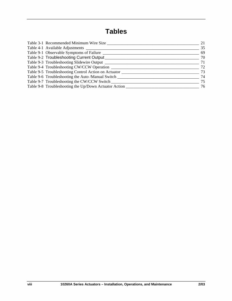
Tables Table 3-1 Recommended Minimum Wire Size ____________________________________________ 21 Table 4-1 Available Adjustments ______________________________________________________ 35 Table 9-1 Observable Symptoms of Failure ______________________________________________ 69 Table 9-2 Troubleshooting Current Output_____________________________________________ 70 Table 9-3 Troubleshooting Slidewire Output _____________________________________________ 71 Table 9-4 Troubleshooting CW/CCW Operation __________________________________________ 72 Table 9-5 Troubleshooting Control Action on Actuator _____________________________________ 73 Table 9-6 Troubleshooting the Auto /Manual Switch _______________________________________ 74 Table 9-7 Troubleshooting the CW/CCW Switch __________________________________________ 75 Table 9-8 Troubleshooting the Up/Down Actuator Action ___________________________________ 76
2/03 10260A Series Actuators – Installation, Operations, and Maintenance ix
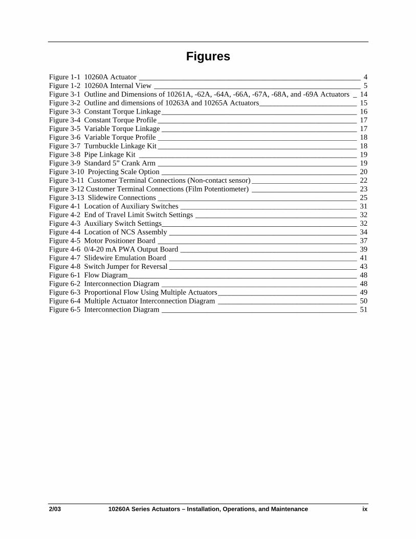
Figures Figure 1-1 10260A Actuator ___________________________________________________________ 4 Figure 1-2 10260A Internal View _______________________________________________________ 5 Figure 3-1 Outline and Dimensions of 10261A, -62A, -64A, -66A, -67A, -68A, and -69A Actuators _ 14 Figure 3-2 Outline and dimensions of 10263A and 10265A Actuators__________________________ 15 Figure 3-3 Constant Torque Linkage____________________________________________________ 16 Figure 3-4 Constant Torque Profile _____________________________________________________ 17 Figure 3-5 Variable Torque Linkage ____________________________________________________ 17 Figure 3-6 Variable Torque Profile _____________________________________________________ 18 Figure 3-7 Turnbuckle Linkage Kit _____________________________________________________ 18 Figure 3-8 Pipe Linkage Kit __________________________________________________________ 19 Figure 3-9 Standard 5” Crank Arm _____________________________________________________ 19 Figure 3-10 Projecting Scale Option ____________________________________________________ 20 Figure 3-11 Customer Terminal Connections (Non-contact sensor) ____________________________ 22 Figure 3-12 Customer Terminal Connections (Film Potentiometer) ____________________________ 23 Figure 3-13 Slidewire Connections _____________________________________________________ 25 Figure 4-1 Location of Auxiliary Switches _______________________________________________ 31 Figure 4-2 End of Travel Limit Switch Settings ___________________________________________ 32 Figure 4-3 Auxiliary Switch Settings____________________________________________________ 32 Figure 4-4 Location of NCS Assembly __________________________________________________ 34 Figure 4-5 Motor Positioner Board _____________________________________________________ 37 Figure 4-6 0/4-20 mA PWA Output Board _______________________________________________ 39 Figure 4-7 Slidewire Emulation Board __________________________________________________ 41 Figure 4-8 Switch Jumper for Reversal __________________________________________________ 43 Figure 6-1 Flow Diagram_____________________________________________________________ 48 Figure 6-2 Interconnection Diagram ____________________________________________________ 48 Figure 6-3 Proportional Flow Using Multiple Actuators_____________________________________ 49 Figure 6-4 Multiple Actuator Interconnection Diagram _____________________________________ 50 Figure 6-5 Interconnection Diagram ____________________________________________________ 51

x 10260A Series Actuators – Installation, Operations, and Maintenance 2/03

Introduction
2/03 10260A Series Actuators – Installation, Operations, and Maintenance 1
1. Introduction
1.1 Product Description Honeywell's 10260A industrially rated rotary control actuators are precision engineered for exceptional reliability, accurate positioning, and low maintenance. Designed for very precise positioning of dampers and quarter turn valves in the power an processing industries, the 10260A performs especially well in extremely demanding environments requiring continuous-duty, high reliability, and low maintenance.
Precise positioning of the actuator is achieved through state-of-the-art motor control and positioning electronics. The motor starts and stops instantaneously, preventing overshoot and hunting. Positioning repeatabililty of 0.2 % span or better is achievable for extremely tight process control to take full advantage of modern controllers.
A no-burnout synchronous induction motor is combined with a heavy-duty precision machined output worm gear mesh providing a responsive, low maintenance, and non-backdriving actuator. Accidental stalls up to 100 hours can be withstood without damage to the gear train. End-of-travel limit switches are provided as standard to prevent damage to the valve or damper and are backed up by Mechanical stops.
Honeywell electric actuators provide instantaneous response to a demand signal, eliminating system non-linearity due to dead time. Additionally, since the actuator is electric, the costs associated with providing and maintaining a clean, dry air supply are eliminated.
A Heavy duty cast crank arm and precision rod-end bearing is provided with each 10260A actuator. Crank arms can be positioned at any angle on the output shaft and an adjustable radius is provided to allow flexibility in linkage set-up.
All 10260A actuators are equipped with a manual handwheel for operation during loss of power or installation. A local auto/manual handswitch can be provided for local operation and has an “out of auto” contact to annunciate that condition.
1.2 Applications Honeywell actuators have a long and respected history in the industrial actuator market. 10260A actuators are designed for precision modulation of final control devices such as dampers, vanes, fluid couplings, scoop tubes, fuel/air ratio valves, windbox dampers, and coal mill dampers, and quarter turn valves. The robustness of the design serves as the basis for long-term reliability and reduced operating costs.
1.3 Features
1.3.1 Non-contact Position Sensing (NCS) with True Shaft Position Indication
Introduction
Non-contact position sensing eliminates maintenance problems and nuisance shutdowns that are common with slidewire position sensing. The non-contact position sensor replaces the slidewire and wiper assembly for position sensing. Once calibrated, the non-contacting position sensor requires no maintenance.
Description The non-contact position sensing assembly consists of a position sensor, an output board, and a bracket as shown in Figure 1-2. The position sensor “spoiler” is connected directly to the output shaft, reflecting true shaft position. As the output shaft rotates, the sensor “spoiler” rotates and the sensing circuit board detects

10260A Series Actuators Installation, Operations, and Maintenance Manual
2 10260A Series Actuators – Installation, Operations, and Maintenance 2/03
the change in position. Sensing is accomplished by changing the magnetic field created by the coils in the sensing circuit board. There is no contact between circuit board and spoilers.
1.3.2 Slidewire Emulation
Introduction
A truly unique feature, slidewire emulation allows direct replacement of existing three-wire control actuators without requiring controller changes while gaining all of the advantages of the maintenance-free non-contact sensing. This is ideal for replacement of installed actuators that cause control problems due to slidewire wear.
Description
The slidewire emulation assembly consists of a non-contact position sensor, an output board, and a bracket as shown in Figure 1-2. The position sensor is identical to that described in Section 1.3.1.
A potentiometric voltage from the controller is supplied to the slidewire emulation circuit. This voltage is ratiometrically conditioned with respect to the output shaft position from 0 % to 100 % and is available to the controller. Voltages of 1 Vdc to 20 Vdc are accepted and this device will emulate 100 ohm to 1000 ohm slidewires.
1.3.3 Film Potentiometer
Introduction
Film potentiometer position sensing eliminates maintenance problems and nuisance shutdowns common with slidewire and wiper assembly for position sensing.
Description The film potentiometer is connected directly to the output shaft reflecting true shaft position. The film potentiometer is 1000 ohms over the actuator’s 90 degree travel. Other ohmic values can be accomplished using an appropriate shunting resistor.
1.3.4 Motor Positioner Board
Introduction
The Honeywell Motor Positioner Board accepts a current input signal to provide internal closed loop control of the position of the actuator. The Honeywell Motor Positioner makes positive position control possible with current output controllers.
Description The Motor Positioner operates raise/lower switch contacts (triacs) which control power to the reversing motor in the actuator. The actuators integral Non-Contact Sensor or Film Potentiometer provide the position feedback signal to the Motor Positioner. Input signal ranges are adjustable from 0.2 Vdc to 1 Vdc, up to 1 Vdc to 5 Vdc. By use of an appropriate shunt resistor, controller current outputs of 4-20 mA dc, 1-5 mA dc, 10-50 mA dc, can be achieved.
Fail-safe features are also provided. On loss of input signal, the Motor Positioner may be preset to drive the motor upscale, downscale, to a particular position, or to stop where it is. In the event of actuator NCS failure (broken wiper) or film potentiometer broken wiper, the Motor Positioner can be set to drive the motor fully upscale or downscale. The Motor Positioner will also accept slidewire input. For master/follower applications, the Motor Positioner will position a “follower” actuator in accordance with a slidewire input signal from a “master” actuator. The ratio between master and follower movement is
Introduction
2/03 10260A Series Actuators – Installation, Operations, and Maintenance 3
adjustable by means of a span control. A bias offset may also be induced between master and follower by means of a zero adjustment. For follower operations in master-follower systems, the master actuator retransmitting slidewire can range from 100 ohms to 1000 ohms. The Motor Positioner is a printed circuit board that is integrally mounted in a 10260A Series Actuator terminal cover. See Figure 1-2. The terminal cover is gasketed to provide weather resistance.
1.3.5 Auto/Manual Switch The Auto/Manual electric handswitch with auxiliary contacts indicating an "Out-of-Auto" position is available for local electric control.
1.3.6 Self-Locking/Releasing Gear Train The worm gear output combination is self-locking and self-releasing and maintains position upon loss of power. It is designed to hold greater than two times the rated output torque in a back-driving condition. This design provides superior reliability without the maintenance associated with other self-locking and brake mechanisms.
1.3.7 Motor A 100 % duty cycle synchronous induction motor provides crisp and responsive movement for precise and accurate positioning. The very low current draw during operation or in stall combined with the no-burnout characteristics of the motor result in low maintenance, high reliability, and long life.
1.3.8 Manual Operation A manual handwheel is provided for positioning of the actuator during power outages or initial installation. The design of the handwheel allows for positioning of the actuator safely under full load conditions.
1.3.9 All Position Mounting Honeywell 10260A actuators may be mounted in any orientation making retrofit in tight locations easier.
1.3.10 Field Reversible NCS: As factory shipped, the actuator is set for counter-clockwise rotation. By changing a jumper and switch, the actuator can be set for clockwise rotation. Re-calibration is not required.
Film Potentiometer: As factory shipped, the actuator is set for counterclockwise rotation. By changing a switch and interchanging the film potentiometer leads, the actuator can be set for clockwise rotation. Re-calibration may be required.
1.3.11 Customer Connections The 10260A now has dedicated wiring terminals for ease of installation. See section 3.4.2 Customer Connections for specific placement.
1.3.12 Warranty The 10260A actuator warranty is effective for 30 months from the date of shipment or 24 months from the date of installation whichever comes first.

10260A Series Actuators Installation, Operations, and Maintenance Manual
4 10260A Series Actuators – Installation, Operations, and Maintenance 2/03
1.4 Honeywell Linkage Kits Honeywell turnbuckle and pipe linkage kits are available and are recommended to provide optimal positioning performance. The rod-end bearing connections eliminate all linkage hysteresis giving accurate and repeatable positioning of the final control element. Honeywell has designed a linkage analysis program (HAL) that is used to deign linkage set-up.
Non-Contact Sensor& Switch Cover
Crank Arm and Rod End
Auto/M anualSwi tc h
Terminal Cover
Hand - whee l
Figure 1-1 10260A Actuator

Introduction
2/03 10260A Series Actuators – Installation, Operations, and Maintenance 5
A u t o / M a n u alS w i t c h
Output Board
F i e l d R e v e r sible Switch
C u s t o m e r C o n n e c t i o n s
N o n - C o n t a c t P o s i t i o n S e n s o r
L i m i t S w i t c h esa n d
A u x i l l i a r y S w i t ches
H a n d w h e e l
Figure 1-2 10260A Internal View

10260A Series Actuators Installation, Operations, and Maintenance Manual
6 10260A Series Actuators – Installation, Operations, and Maintenance 2/03

Specifications and Model Selection Guide
2/03 10260A Series Actuators – Installation, Operations, and Maintenance 7
2. Specifications and Model Selection Guide
2.1 Introduction This chapter provides the user with the specifications and the Model Selection Guide for the 10260A Series Actuator.
2.2 Specifications Specification – General
Physical Weight 40 lb. (18 kg) net
Enclosure Precision machined Aluminum alloy casting, finished in light gray powder coat epoxy.
Gear train Alloy steel, high efficiency steel spur gear primary train with safety fused idler gear. Precision ground, self locking/self releasing worm gear final mesh.
Mechanical stops To prevent over-travel
Operating Temperature –30 °C to +85 °C (–20 °F to +185 °F)
Storage Temperature –40 °C to +93 °C (–40 °C to +200 °F)
Relative Humidity Fully operable over the range of 0-99 % R.H. non-condensing
Scale 0 % to 100 % corresponding to full crank arm travel.
Crank Arm Adjustable radii (1-7/16" to a maximum of 5"). Position adjustable through 360° rotation. Optional 12” crank arm adjustable 0-12” radii.
Output Shaft 1" diameter, 1-1/2" long is standard on 10261A, 10262A, 10264A, 10266A, 10267A, 10268A. 1" diameter, 2" long is standard on 10263A, 10265A and 10269A optional on other models.
Rotation 900 degrees between 0 % and 100 % on scale, limited by mechanical stops.
Direction of Rotation Field selectable via switch and jumper. Default = CCW (determined looking into the shaft)
Manual Handwheel Provides a means of positioning the actuator in the event of a power failure or set-up.
Lubrication Texaco Starplex 2 EP Grease
Fuses Bussmann GDB1.6: 1.6 Amp Fast Littlefuse 312001: 1.0 Amp Fast

10260A Series Actuators Installation, Operations, and Maintenance Manual
8 10260A Series Actuators – Installation, Operations, and Maintenance 2/03
Physical Output Torque/Full Travel Stroking Time
Model #
10261A
10262A
10264A
10266A
10267A
10268A
10269A
10263A
10265A
Torque Lb.-ft N-M
10 15
20 27
40 55
60 80
40 55
80 110
150 200
200 270
300 400
Output Shaft Speed sec/90° @ 60Hz @ 50Hz
10 12
20 24
40 48
60 72
20 24
40 48
60 72
40 48
60 72
Electrical Power Input 120 Vac single phase, 50 or 60 Hz
240 Vac single phase, 50 or 60 Hz
Motor Instant start/stop, non-coasting, non-burnout, continuous duty permanent magnet synchronous induction motor. Can be stalled up to 100 hours without damage.
Motor Current = No load = full load = locked rotor
Model No.
10261A, 62A, 64A, 66A
10263A, 10265A
10267A, 68A, 69A
120 V, 50/60 Hz
0.4 A (48 VA)
1.0 A (120 VA)
0.8 A (96 VA)
240 V, 50/60 Hz
0.3 A (24 VA)
1.0 A (60 VA)
0.3 A (36 VA)
Loss of Power Stays in Place
Local Auto/Manual Switch Optional - allows local and automatic operation of the actuator.
Limit Switches Standard - Two SPDT end of travel limits rated (10 A at 125 Vac, 5 A at 250 Vac).
Auxiliary Switches Optional - Up to 4 additional SPDT switches rated (10 A at 125 Vac, 5 A at 250 Vac)
Certifications
CE Compliance 89/336/EEC EMC Directive, 73/23/EEC Low Voltage Directive.
NEMA 4 Optional
Torque Settings of Crank Arm Bolts
Clamp Bolt Standard Arm (p/n 087449) (1-7/16–5 in. adjustment): 85 lb.-ft.
Optional Long Arm (p/n 154007) (0–12 in. adjustment): 85 lb.-ft.
Rod End Bolt Standard and long arms: 30-35 lb.-ft
Specifications and Model Selection Guide
2/03 10260A Series Actuators – Installation, Operations, and Maintenance 9
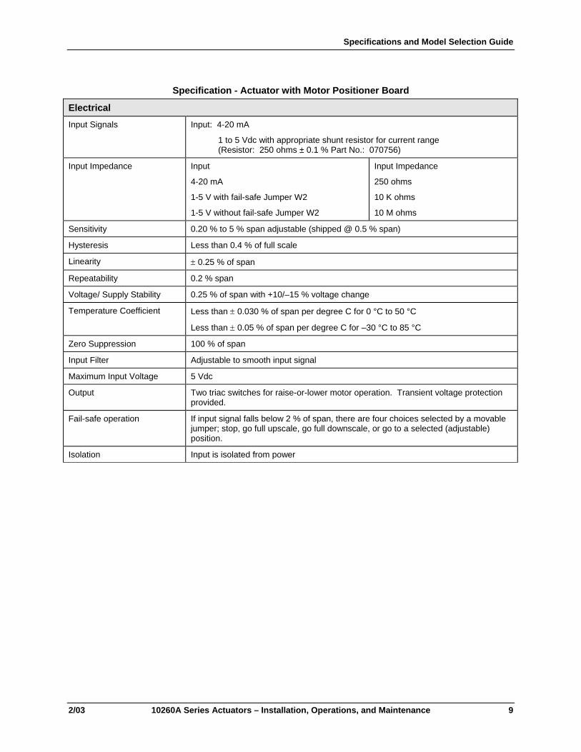
Specification - Actuator with Motor Positioner Board
Electrical Input Signals Input: 4-20 mA
1 to 5 Vdc with appropriate shunt resistor for current range (Resistor: 250 ohms ± 0.1 % Part No.: 070756)
Input Impedance Input
4-20 mA
1-5 V with fail-safe Jumper W2
1-5 V without fail-safe Jumper W2
Input Impedance
250 ohms
10 K ohms
10 M ohms
Sensitivity 0.20 % to 5 % span adjustable (shipped @ 0.5 % span)
Hysteresis Less than 0.4 % of full scale
Linearity ± 0.25 % of span
Repeatability 0.2 % span
Voltage/ Supply Stability 0.25 % of span with +10/–15 % voltage change
Temperature Coefficient Less than ± 0.030 % of span per degree C for 0 °C to 50 °C
Less than ± 0.05 % of span per degree C for –30 °C to 85 °C
Zero Suppression 100 % of span
Input Filter Adjustable to smooth input signal
Maximum Input Voltage 5 Vdc
Output Two triac switches for raise-or-lower motor operation. Transient voltage protection provided.
Fail-safe operation If input signal falls below 2 % of span, there are four choices selected by a movable jumper; stop, go full upscale, go full downscale, or go to a selected (adjustable) position.
Isolation Input is isolated from power

10260A Series Actuators Installation, Operations, and Maintenance Manual
10 10260A Series Actuators – Installation, Operations, and Maintenance 2/03
Specification - Actuator with Output Board
Electrical Feedback signals 0-20 mA
4-20 mA
1-5 Vdc with 250 ohm resistor ± 0.1 %
0-16 Vdc with 800 ohm resistor ± 0.1 %
Slidewire Emulation Provides output voltage ratiometric to shaft position and potentiometric to supply voltage (1-20 Vdc) without a slidewire. Emulates a 100 ohms to 1000 ohm slidewire. 10 mA output maximum.
Isolation Output is isolated from power and input signal by 240 Vac
Load Requirement (4-20) Current Out — 0-1000 ohms

Specifications and Model Selection Guide
2/03 10260A Series Actuators – Installation, Operations, and Maintenance 11
2.3 Model Selection Guide Instructions
Select the desired key number. The arrow to the right marks the selection available.Make the desired selections from Tables I thru VII using the column below the arrow.A dot ( ) denotes unrestricted availability.
Key Number I II III IV V VI VII_ _ _ _ _ _ - _ - _ - _ _ - _ - _ _ _ _ _ - _ _ _ - _ _
KEY NUMBER - Electronics Selection AvailabilityOutput Torque Full Travel Stroking - Time in Seconds(lb. - ft.) (N - M) 60 Hz 50 Hz
10 (15) 10 12 10261A20 (27) 20 24 10262A40 (55) 40 48 10264A60 (80) 60 72 10266A40 (55) 20 24 10267A80 (110) 40 48 10268A150 (200) 60 72 10269A200 (270) 40 48 10263A300 (400) 60 72 10265A
TABLE I - POWER SUPPLY - SINGLE PHASE120 VAC 60 Hz Single Phase 120 VAC 60Hz Motor 1120 VAC 50 Hz Single Phase 120 VAC 50Hz Motor 2220/240 VAC 60 Hz Single Phase 220/240 VAC 60Hz Motor 3220/240 VAC 50 Hz Single Phase 220/240 VAC 50Hz Motor 4TABLE II - CONTROLSUp/Dn Drive Up/Dn 04-20mAdc / 1-5Vdc 4-20mAdc or 1-5Vdc (w/resistor change) 1TABLE III - CUSTOMER POSITION OUTPUTSNone No position outputs provided 00SEC (Note 1) One slidewire emulation output (3-Wire Pos. Proportional) 01Analog Output (Note 2) 4-20mAdc, 0-20mAdc, 0-5Vdc, 1-5Vdc, or 0-1.25Vdc 03Film Potentiometer Dual 1000 ohm 04 d
(Note 3) Single 1000 ohm 05 eTABLE IV - CONTACT OUTPUTSLimit Switches 1 CW & 1 CCW Limit Switch 0Limit/Auxiliary Switches 1CW, 1CCW, & 2 Auxiliary SPDT Switches 2Limit/Auxiliary Switches 1CW, 1CCW, & 4 Auxiliary SPDT Switches 4Limit/Auto-Manual 1CW, 1CCW, Auto/Man Switch 5Limit/Auto/Auxiliary 1CW, 1CCW, Auto/Man Switch & 2 Aux 7Limit/Auto/Auxiliary 1CW, 1CCW, Auto/Man Switch & 4 Aux 9
Note 1: Slidewire emulation output is a solid state emulation circuit providing a ratiometric voltage slidewire signal without utilizing an actual slidewire. Emulates slidewires using voltages up to 20.0Vdc.
Note 2: Analog output is factory set to 4-20mAdc. Additional listed outputs are customer selectable byjumper and/or output resistor selection.
Note 3: 135 ohm available with 158 ohm resistor supplied with actuator.100 ohm available with 110 ohm resistor supplied with actuator.
10260A Series Actuators Installation, Operations, and Maintenance Manual
12 10260A Series Actuators – Installation, Operations, and Maintenance 2/03
1A, 2A, 3A, 4A, 5A6A, 7A, 8A, 9A1026_ _
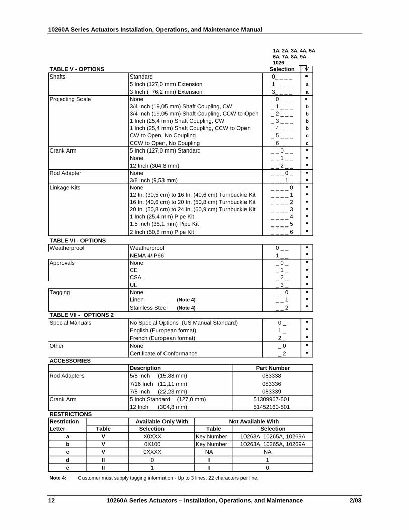
TABLE V - OPTIONS SelectionShafts Standard 0_ _ _ _
5 Inch (127,0 mm) Extension 1_ _ _ _ a3 Inch ( 76,2 mm) Extension 3_ _ _ _ a
Projecting Scale None _ 0 _ _ _3/4 Inch (19,05 mm) Shaft Coupling, CW _ 1 _ _ _ b3/4 Inch (19,05 mm) Shaft Coupling, CCW to Open _ 2 _ _ _ b1 Inch (25,4 mm) Shaft Coupling, CW _ 3 _ _ _ b1 Inch (25,4 mm) Shaft Coupling, CCW to Open _ 4 _ _ _ bCW to Open, No Coupling _ 5 _ _ _ cCCW to Open, No Coupling _ 6 _ _ _ c
Crank Arm 5 Inch (127,0 mm) Standard _ _ 0 _ _None _ _ 1 _ _12 Inch (304,8 mm) _ _ 2 _ _
Rod Adapter None _ _ _ 0 _3/8 Inch (9,53 mm) _ _ _ 1 _
Linkage Kits None _ _ _ _ 012 In. (30,5 cm) to 16 In. (40,6 cm) Turnbuckle Kit _ _ _ _ 116 In. (40,6 cm) to 20 In. (50,8 cm) Turnbuckle Kit _ _ _ _ 220 In. (50,8 cm) to 24 In. (60,9 cm) Turnbuckle Kit _ _ _ _ 31 Inch (25,4 mm) Pipe Kit _ _ _ _ 41.5 Inch (38,1 mm) Pipe Kit _ _ _ _ 52 Inch (50,8 mm) Pipe Kit _ _ _ _ 6
TABLE VI - OPTIONSWeatherproof Weatherproof 0 _ _
NEMA 4/IP66 1 _ _Approvals None _ 0 _
CE _ 1 _CSA _ 2 _UL _ 3 _
Tagging None _ _ 0Linen (Note 4) _ _ 1Stainless Steel (Note 4) _ _ 2
TABLE VII - OPTIONS 2Special Manuals No Special Options (US Manual Standard) 0 _
English (European format) 1 _French (European format) 2 _
Other None _ 0Certificate of Conformance _ 2
ACCESSORIESDescription
Rod Adapters 5/8 Inch (15,88 mm)7/16 Inch (11,11 mm)7/8 Inch (22,23 mm)
Crank Arm 5 Inch Standard (127,0 mm)12 Inch (304,8 mm)
RESTRICTIONSRestriction Available Only With Not Available WithLetter Table Selection Table Selection
a V Key Number 10263A, 10265A, 10269Ab V Key Number 10263A, 10265A, 10269Ac V NA NA
II II 1II II 0
Note 4: Customer must supply tagging information - Up to 3 lines, 22 characters per line.
0XXXX
Part Number
X0XXX0X100
51309967-50151452160-501
083338083336083339
de
01

Installation
2/03 10260A Series Actuators – Installation, Operations, and Maintenance 13
3. Installation
3.1 Introduction This chapter provides the user with all the mechanical and electrical information required to get the 10260A Series Actuator up and running in the user’s specific application. This chapter also includes safety precautions and unpacking instructions.
3.2 Before Starting
3.2.1 Unpacking If there are visible signs of damage to the shipping container, notify the carrier and Honeywell immediately.
If there is no visible damage, compare the contents with the packing list. Notify the carrier and Honeywell immediately if there is equipment damage or shortage.
Please do not return goods without contacting Honeywell in advance. The contact number is 1-800-423-9883.
3.2.2 Site Selection Mount the actuator in a location where it will be easily accessible for maintenance and for manual operation by means of the handwheel. The exact location must be determined in accordance with the linkage used.
It is important that the actuator be mounted securely to a solid foundation commensurate with the maximum torque developed. Use studs or bolts that are as large as the foot mounting holes.
The following precautions should be taken when selecting an installation site.
• Shield the actuator from rain or snow unless the NEMA 4 option was selected.
• Allocate sufficient space around the actuator for the removal of all covers to permit inspection or calibration and to provide access to the handwheel.
• Use auxiliary shielding to protect the actuator from excessive heat or cold outside of the rating of the Actuator and from corrosive elements
• Ambient temperature should not exceed 185 °F (85 °C).
• The minimum low temperature limit is –20 °F (–30 °C).
3.2.3 Outline Dimension Drawings An outline and dimension drawing for mounting is furnished with each unit. See also Figure 3-1 and Figure 3-2.

14 10260A Series Actuators – Installation, Operations, and Maintenance 2/03
5.50
0 [1
39.7
0]
9.81
2 [2
49.2
2]
8.93
8 [2
27.0
3]
4.46
9 [1
13.5
1]
1.62
5 [4
1.28
]
DIA
3.37
5 [8
5.73
]
11.1
25 [2
82.5
8] M
IN F
OR
CO
VE
R R
EM
OV
EL
FULL
CR
AN
KTR
AVEL
90°
1/2-
20U
NF-
2B X
1.2
39(3
1.47
)D
EE
P TH
RE
AD
1/2-
13U
NC
-2B
X 2
LO
NG
GR
AD
E 5
OR
BE
TTE
R B
OLT
4.50
01.
938
(49.
21)
(114
.3)
TAP
PE
D H
OLE
FO
R1"
CO
ND
UIT
.
AC
CE
SS C
OV
ER
TO
TER
MIN
AL
BO
AR
D
2.50
0(6
3.50
)
ACC
ES
S C
OV
ER
4.00
0
4.71
8
5/16
-24
UN
F-2B
x.50
0 (1
2.7)
DP.
TYP.
4 T
AP
PE
D H
OLE
S E
AC
H S
IDE
1.00
0 D
IA. (
25.4
)S
HA
FT
0.68
8(1
7.46
)
HA
ND
WH
EEL
MO
TOR
(RE
F.)
(RE
F.)
7.68
8
3.84
4(1
95.2
6)
(97.
63)
MO
TOR
.281
(7.1
4) D
IA.H
OLE
(4)
AC
CE
SS
CO
VE
R T
OS
PU
R G
EA
RIN
G
(121
.43)
(101
.6)
HA
ND
WH
EE
L
1026
9 S
ERIE
S H
AS
AKN
UR
LED
OU
TPU
T SH
AFT
SPA
CER
0.43
7 [1
1.10
]
0.37
5
0.59
6 [1
5.15
]
2.71
8 [6
9.04
]
1.37
5 [3
4.93
]
2.12
5 [5
3.98
]
5.37
5 [1
36.5
3]
2.03
1 [5
1.59
]
0.43
7 [1
1.10
]
0.59
6 [1
5.15
]
5.00
0
2.12
5
8.62
5
8.18
7 [2
07.9
5]
10.1
25 [2
57.1
8]
1.50
0 [3
8.10
]
0.68
7 [1
7.45
]
11.0
62 [2
80.9
7][1
27.0
0] M
AX
53.9
8
[219
.08]
[9.5
2]
NOTE
S:
1. A
CTUA
TOR
CAN
BE M
OUNT
ED IN
ANY
POS
ITIO
N.2.
PRO
VIDE
ADE
QUAT
E CL
EARA
NCE
AT A
LL A
CCES
S CO
VERS
FO
R
SER
VICI
NG A
ND A
DJUS
TMEN
TS.
3. W
IRIN
G DI
AGRA
M IS
LOC
ATED
ON
THE
INSI
DE O
F TH
E
CRAN
K AR
M (G
OLD)
CON
FIGU
RATI
ONTO
MAT
CH C
AST
IRON
(SILV
ER) C
RANK
ARM
ROD
END
CENT
ERLIN
E. U
SE K
IT 51
3097
55-5
01
Figure 3-1 Outline and Dimensions of 10261A, -62A, -64A, -66A, -67A, -68A, and -69A Actuators
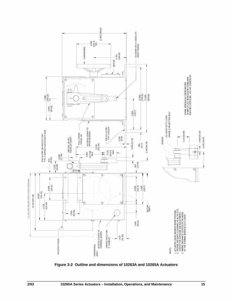
2/03 10260A Series Actuators – Installation, Operations, and Maintenance 15
11.0
62 [2
80,9
7]
5.50
0(1
39.7
)
4.50
01.
938
(49.
21)
(114
.3)
.563
(14.
29)
1.62
5(4
1.28
)
TAPP
ED H
OLE
FO
R1"
CO
ND
UIT
.
ACC
ESS
CO
VER
TO
TER
MIN
AL B
OAR
D
2.50
0(6
3.50
)
AC
CE
SS C
OVE
R
8.31
3
4.00
0
4.71
8
.813
(20.
64)
5/16
-24
UN
F-2B
x.50
0 (1
2.7)
DP.
TYP.
4 T
APPE
D H
OLE
S E
ACH
SID
E
.999
DIA
. (25
.38
)K
NU
RLE
D S
HA
FT
0.68
8(1
7.46
)
2.12
5(5
3.98
)
HAN
DW
HEE
L
MO
TOR
(REF
.)
(REF
.)
7.68
8
3.84
4(1
95.2
6)
(97.
63)
6.00
0(1
52.4
) D
IA.
5.75
0(1
46.0
5)
MO
TOR
12.0
00(3
04.8
0)
11.0
00
5.50
0
0.25
0
.438
(11.
11) D
IA.
TYP.
4 H
OLE
S
.500
(12.
7)
ACC
ESS
CO
VER
TO
SPU
R G
EAR
ING
(211
.15)
(121
.43)
(101
.6)
(6.3
5)
(139
.7)
(279
.40)
HAN
DW
HEE
L
8.75
0(2
22.2
5)
3.10
5 [7
8,87
]
SPAC
ER
10.1
25 [2
57.1
8]
FULL
CR
ANK
TRAV
EL 9
0°
1/2-
20U
NF-
2B X
1.2
39(3
1.47
)D
EEP
THR
EAD
MOTOR
2.12
5[5
3.97
]M
AX
5.00
0[1
27.0
0]M
AX
2.15
5 [5
4.74
]
0.59
6 [1
5.15
] 1/2-
13U
NC
-2B
X 2
LON
GG
RAD
E 5
OR
BE
TTER
BO
LT
0.60
3 [1
5.32
]
2.12
5 [5
3.98
]
11.1
25 (2
82.5
8] M
IN F
OR
CO
VER
REM
OVA
L
CRAN
K A
RM (G
OLD)
CON
FIGU
RATI
ONTO
MAT
CH C
AST
IRON
(SILV
ER) C
RANK
ARM
ROD
END
CENT
ERLIN
E. U
SE K
IT 5
1309
755-
501
NOTE
S:
1. A
CTUA
TOR
CAN
BE M
OUNT
ED IN
ANY
POS
ITIO
N.2.
PRO
VIDE
ADE
QUAT
E CL
EARA
NCE
AT A
LL A
CCES
S
COV
ERS
FOR
SERV
ICIN
G AN
D AD
JUST
MENT
S.3.
WIR
ING
DIAG
RAM
IS LO
CATE
D ON
THE
INSI
DE
O
F TH
E TE
RMIN
AL B
OARD
ACC
ESS
COVE
R.
Figure 3-2 Outline and dimensions of 10263A and 10265A Actuators

10260A Series Actuators Installation, Operations, and Maintenance Manual
16 10260A Series Actuators – Installation, Operations, and Maintenance 2/03
3.3 Mechanical Installation
3.3.1 General Install the 10260A series actuator in a convenient location in any orientation. Firmly bolt the 10260A to a mounting surface that will not distort when subjected to the torque stresses generated by the actuator. The output shaft of the actuator should be parallel to the output shaft of the driven device. The output shaft crank arm is fully adjustable through 360°.
3.3.2 Linkage Set-up
General Many applications require the use of a linkage assembly and often the final control element does not have a linear torque curve. The 10260A Series Actuator linkage can be set up to achieve an optimal delivered torque distribution for specific applications. To assist with linkage design, Honeywell offers a linkage analysis software package (HAL). The software can be ordered as P/N 51197910-001.
Constant Torque Linkage A constant torque linkage is employed when it is desired to provide a linear torque profile throughout the full range of final control element travel. In this situation, the actuator and driven crank arms will be set-up proportionally with respect to each other. Figure 3-3 shows a general linkage setup to achieve a linear torque profile and Figure 3-4 shows the resultant profile.
VerticalCenterline
45° 45°
VerticalCenterline
45° 45°
Start Stop Close Open
Drive UnitCrank Arm
DamperCrank Arm
Linkage
Horizontal Offset
a/n 23199 Figure 3-3 Constant Torque Linkage

Installation
2/03 10260A Series Actuators – Installation, Operations, and Maintenance 17
Figure 3-4 Constant Torque Profile
Variable Torque Linkage A variable torque linkage is employed when it is desired to provide a non-linear torque profile throughout the full range of final control element travel. In this general situation, the actuator and driven crank arms will be set up to provide a higher torque for seating or unseating the final control element. Figure 3-5 shows a general linkage setup to achieve a non-linear torque profile and Figure 3-6 shows the resultant profile. Note that this linkage can be characterized in many different ways by varying start angles and rotation requirements of both the Actuator Crank Arm and the Driven Arm.
VerticalCenterline
5°
VerticalCenterline
45° 45°
Close Open
ActuatorCrank Arm
DamperCrank Arm
Linkage
Horizontal Offseta/n 23200
Figure 3-5 Variable Torque Linkage

10260A Series Actuators Installation, Operations, and Maintenance Manual
18 10260A Series Actuators – Installation, Operations, and Maintenance 2/03
Figure 3-6 Variable Torque Profile
Turnbuckle Linkage Kits (See Section 8 for Kit numbers.)
These kits are to be used where short lengths are required. These lengths range from 12 to 24 inches and refer to the rod end center - to - center distance. All turnbuckle kits include the turnbuckle, load rod end (left-hand thread), connecting rods and locking nuts. The nut and bolt needed to connect the rod end to the load are supplied by the Customer. The actuator rod end (right-hand thread), nut and bolt are supplied with the actuator. These kits can be ordered with the Actuator via Table VI of the Model Selection Guide or separately as identified in section 8.4 of this manual.
Rod end, nut and bolt aresupplied with the actuator
1/2"-20 right-hand threads 0.5"-20 left-hand threads
Customer supplied nut and bolt
12 to 24 inches
a/n 23201 Figure 3-7 Turnbuckle Linkage Kit
Pipe Linkage Kits (See Section 8 for Kit numbers.)
These kits are used for linkage lengths from 24 inches to 120 inches (60 cm to 305 cm). All pipe linkage kits include the mechanical pipe couplings, load rod end (left-hand thread), connecting rods and locking nuts. The Customer must supply a piece of schedule 40 pipe * (both ends with right-hand NP threads) and a nut and bolt to connect the rod end to the load. The actuator rod end (right-hand thread), nut and bolt are supplied with the actuator. These kits can be ordered with the Actuator using Table VI of the Model Selection Guide or separately as identified in Section 8, Replacement/Recommended Spare Parts of this manual.

Installation
2/03 10260A Series Actuators – Installation, Operations, and Maintenance 19
Rod end, nut and bolt aresupplied with the actuator
1/2"-20 right-hand threads 1/2"-20 left-hand threads
Customer supplied nut and bolt
24 to 120 inches
Customer supplied pipe*
* cut to sizewith
standard NPT both ends a/n 23202 Figure 3-8 Pipe Linkage Kit
*Pipe length = Overall linkage length minus (-) 17 inches (43 cm).
Actuator Crank Arms The 10260A Series Actuator comes standard with a 5” crank arm (p/n 51309967-501) or an optional crank arm adjustable 0”-12” (p/n 51452160-501).
The 10260A Series Actuator crank arm uses a standard ½” rod end to compliment the turnbuckle and pipe linkage kits. The crank arm connects the link rod using a ½” rod end and a hex link rod adapter. For applications which use a link rod, a link rod adapter is available is available as an option in the Model Selection Guide.
1/2" Rod End
Link Rod Adapter
Link Rod
Set Screws
Insert the Link Rod Completely into the Link rodAdapter and tighten the (2) set screws withsufficient force to hold the l ink rod.
Figure 3-9 Standard 5” Crank Arm

10260A Series Actuators Installation, Operations, and Maintenance Manual
20 10260A Series Actuators – Installation, Operations, and Maintenance 2/03
3.3.3 Projecting Scale Option The projecting scale option is available for customers whose actuators are direct coupled that it would be impossible to read the standard scale on the actuator. The projecting scale sits above the actuator and is readable from a distance. See Figure 3-10 Projecting Scale Option.
Figure 3-10 Projecting Scale Option

Installation
2/03 10260A Series Actuators – Installation, Operations, and Maintenance 21
3.4 Electrical Installation
3.4.1 General Wiring Recommendations WARNING
!
Wiring should be performed by qualified personnel only.
Wiring must conform to national and local electrical codes.
In general, stranded copper wire should be used. Unless locally applicable codes dictate otherwise, the recommended minimum wire sizes in Table 3-1 should be observed.
Table 3-1 Recommended Minimum Wire Size Gage No. Description
14 Earth ground wire to common power supply.
18 Earth ground wire to single actuator. 120/240 V ac line leads. +24 V and common signal leads.
Safety Precautions
WARNING
!
An external disconnect switch must be installed to break all current carrying conductors. Turn off power before working on conductors. Failure to observe this precaution may result in serious personal injury.

10260A Series Actuators Installation, Operations, and Maintenance Manual
22 10260A Series Actuators – Installation, Operations, and Maintenance 2/03
3.4.2 Customer Connections WARNING
! The ground terminal must be connected to a reliable earth ground.
WARNING
!
While the unit is powered, a potentially lethal shock hazard exists inside the case. Do not open the case while the unit is powered. Do not access the terminals while the unit is powered.
Figure 3-11 and Figure 3-12 show all the available connections for the 10260A Series actuator (non-contact sensor).
NO
SW 2
33
24
15
OUTPUT CURRE NT
0-20mAdc
4-20mAdc /
NO
4-20mAdc
RESISTOR IS
MOUNTED ON
TERMINAL BOARD
30
CLOSED W HEN
"NOT -IN-AUTO "
SW ITCH CONTACT
AUTO/MAN
28 29
-
INPUT OUTPUT
250
31
-
32
HOT
PE
NEUTRALCO N TR O LL E R
50/ 60 H z
120 V/ 24 0VA C
SUP PLY /
MAI NS P OW ER 1413121110
INTERNALCONNECTIONS
21
NO
2019
NC C
SW 4
2322
NC C
SW 5
SW 1
NO
3L N 4
SW 2
NC
5
SLIDEW IRE EMULATION
36
L
34
FB
35
H
181716
NO
27
NO
2625
NC C
SW 6
NC C
SW 3
SW 2
COMNC
SW 1
6 7
SW 1
COM
8 9
"USE COPPER CONDUCTORS ONLY"
RESISTOR TO BE MOUNTED AT INPUT OFCUSTOMER'S INSTRUMENT
U P D OWN
CONTROLLERDRIVE
Figure 3-11 Customer Terminal Connections (Non-contact sensor)

Installation
2/03 10260A Series Actuators – Installation, Operations, and Maintenance 23
Figure 3-12 Customer Terminal Connections (Film Potentiometer)

10260A Series Actuators Installation, Operations, and Maintenance Manual
24 10260A Series Actuators – Installation, Operations, and Maintenance 2/03
3.4.3 Power Connections For connections, refer to section 3.4.2. Customer Connections.
3.4.4 CE Wiring For CE approved units clamp the ferrite filter provided (087414) around the AC mains power supply wires (hot, neutral, ground) inside the case near the conduit entry.
3.4.5 0/4-20 mA, 0/1-5 Vdc Input Signal Connections For connections, refer to section 3.4.2. Customer Connections. ATTENTION Shielded and grounded cables are recommended.
3.4.6 0/4-20 mA, 0/1-5 Vdc Feedback Signal Connections For connections, refer to section 3.4.2. Customer Connections. ATTENTION Shielded and grounded cables are recommended.

Installation
2/03 10260A Series Actuators – Installation, Operations, and Maintenance 25
3.4.7 Slidewire Emulator Connections For connections, refer to Figure 3-11 and Figure 3-13.
ATTENTION Shielded and grounded cables are recommended.
Motor
UP
DOWN
HOT
NEUTRAL
CCW
12 AUTO
CW/CCWSWITCH
CCW
CONNECTION WHEN AUTO/MAN SWITCHIS NOT PRESENT
G
CW7 6
SW1HL1
NCC
CWLIMITSW
CW
CW
CW
CONNECTION WHENAUTO/MAN SWITCH ISNOT PRESENT
CCWLIMITSW
C NC5 4
9
13
8CCW
CCWK
LL1 SW2
AUTO/MAN SW
SLIDEWIRE EMULATION
L FB H
3534 36SLIDEWIRESUPPLYCOMMON
SLIDEWIREFEEDBACK
SLIDEWIRESUPPLYPOSITIVE
4 TO 20 mA INPUT
+ -
31 30
250 OHM1%
RESISTORMOUNTED ONTERMINALBOARD
4 TO 20 mA OUTPUT
+ -
33 32
250 OHM1%
RESISTORMOUNTED AT INPUT OF CUSTOMER’SINSTRUMENT
CCW
CW
28 29CLOSED WHEN NOT IN AUTO
AUTO/MAN SWITCHAUTO
1
2
11
10
Figure 3-13 Slidewire Connections

Calibration Procedures
2/03 10260A Series Actuators – Installation, Operations, and Maintenance 27
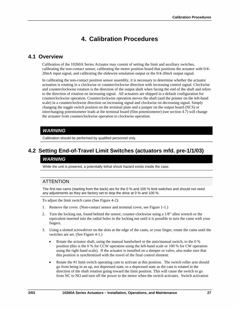
4. Calibration Procedures
4.1 Overview Calibration of the 10260A Series Actuator may consist of setting the limit and auxiliary switches, calibrating the non-contact sensor, calibrating the motor position board that positions the actuator with 0/4-20mA input signal, and calibrating the slidewire emulation output or the 0/4-20mA output signal.
In calibrating the non-contact position sensor assembly, it is necessary to determine whether the actuator actuation is rotating in a clockwise or counterclockwise direction with increasing control signal. Clockwise and counterclockwise rotation is the direction of the output shaft when facing the end of the shaft and refers to the direction of rotation on increasing signal. All actuators are shipped in a default configuration for counterclockwise operation. Counterclockwise operation moves the shaft (and the pointer on the left-hand scale) in a counterclockwise direction on increasing signal and clockwise on decreasing signal. Simply changing the toggle switch position on the terminal plate and a jumper on the output board (NCS) or interchanging potentiometer leads at the terminal board (film potentiometer) (see section 4.7) will change the actuator from counterclockwise operation to clockwise operation.
WARNING Calibration should be performed by qualified personnel only.
4.2 Setting End-of-Travel Limit Switches (actuators mfd. pre-1/1/03) WARNING While the unit is powered, a potentially lethal shock hazard exists inside the case.
ATTENTION The first two cams (starting from the back) are for the 0 % and 100 % limit switches and should not need any adjustments as they are factory set to stop the drive at 0 % and 100 %.
To adjust the limit switch cams (See Figure 4-2):
1. Remove the cover. (Non-contact sensor and terminal cover, see Figure 1-1.)
2. Turn the locking nut, found behind the sensor, counter-clockwise using a 1/8” allen wrench or the equivalent inserted into the radial holes in the locking nut until it is possible to turn the cams with your fingers.
3. Using a slotted screwdriver on the slots at the edge of the cams, or your finger, rotate the cams until the switches are set. (See Figure 4-1.)
• Rotate the actuator shaft, using the manual handwheel or the auto/manual switch, to the 0 % position (this is the 0 % for CCW operation using the left-hand scale or 100 % for CW operation using the right hand scale). If the actuator is installed on a damper or valve, also make sure that this position is synchronized with the travel of the final control element.
• Rotate the #1 limit switch operating cam to activate at this position. The switch roller arm should go from being in an up, not depressed state, to a depressed state as the cam is rotated in the direction of the shaft rotation going toward the limit position. This will cause the switch to go from NC to NO and turn off the power to the motor when the switch activates. Switch activation

10260A Series Actuators Installation, Operations, and Maintenance Manual
28 10260A Series Actuators – Installation, Operations, and Maintenance 2/03
may be detected by the clicking sound or with a continuity tester connected to the terminals. Both the NC and NO contact states are available to the customer at the terminals (see Figure 3-11).
• Rotate the actuator shaft, using the manual handwheel or the auto/manual switch, to the 100 % position (this is 100 % for CCW operation using the left-hand scale or 0 % for CW operation using the right hand scale). If the actuator is installed on a damper or valve, also make sure that this position is synchronized with the travel of the final control element.
• Rotate the #2 limit switch operating cam to activate at this position. The switch roller arm should go from being in an up, not depressed state, to a depressed state as the cam is rotated in the direction of the shaft rotation going toward the limit position. This will cause the switch to go from NC to NO and turn off the power to the motor when the switch activates. Both the NC and NO contact states are available to the customer at the terminals (see Figure 3-11).
• If optional auxiliary switches were ordered, these switches may also be set at this time. (See Section 4.4 for details of setting auxiliary switches.)
4. Once the cams are set in the correct positions, turn the locking nut clockwise until snug tight (it does not have to be “hard” tight and does not have to completely flatten the spring washer).
5. Double check limit switch actuation by first manually driving the actuator to each end of travel and hearing the switch click or by detecting it with a continuity tester. Secondly, drive the actuator to both ends of travel (using the auto/manual switch or by providing minimum and full input signal) and make sure the switches activate and turn off the motor.
ATTENTION Make sure not to set the switch too close to the hard stop.
REFERENCE An unactuated switch will have its normally closed (NC) contacts closed and its normally open (NO) contacts open.
An actuated switch will have its NC contacts become open and its NO contacts become closed. Both NC and NO contacts are available to the customer on the terminal board (Figure 3-11).
An unactuated switch has its roller arm in the up position when adjacent to the reduced diameter portion of the cam.
4.3 Setting End-of-Travel Limit Switches (actuators mfd. after 1/1/03)
WARNING While the unit is powered, a potentially lethal shock hazard exists inside the case.
ATTENTION The first two cams (starting from the back) are for the 0 % and 100 % limit switches and should not need any adjustments as they are factory set to stop the drive at 0 % and 100 %.
To adjust the limit switch cams (see Figure 4-1):

Calibration Procedures
2/03 10260A Series Actuators – Installation, Operations, and Maintenance 29
1. Remove the cover (terminal cover, see Figure 1-1).
2. Using a slotted screwdriver on the slots at the edge of the cams, or your finger, rotate the cams until the switches are set (see Figure 4-1).
• Rotate the actuator shaft, using the manual handwheel or the auto/manual switch, to the 0 % position (this is the 0 % for CCW operation using the left-hand scale or 100 % for CW operation using the right hand scale). If the actuator is installed on a damper or valve, also make sure that this position is synchronized with the travel of the final control element.
• Rotate the #1 limit switch operating cam to activate at this position. The switch roller arm should go from being in an up, not depressed state, to a depressed state as the cam is rotated in the direction of the shaft rotation going toward the limit position. This will cause the switch to go from NC to NO and turn off the power to the motor when the switch activates. Switch activation may be detected by the clicking sound or with a continuity tester connected to the terminals. Both the NC and NO contact states are available to the customer at the terminals (see Figure 3-11).
• Rotate the actuator shaft, using the manual handwheel or the auto/manual switch, to the 100 % position (this is 100 % for CCW operation using the left-hand scale or 0 % for CW operation using the right hand scale). If the actuator is installed on a damper or valve, also make sure that this position is synchronized with the travel of the final control element.
• Rotate the #2 limit switch operating cam to activate at this position. The switch roller arm should go from being in an up, not depressed state, to a depressed state as the cam is rotated in the direction of the shaft rotation going toward the limit position. This will cause the switch to go from NC to NO and turn off the power to the motor when the switch activates. Both the NC and NO contact states are available to the customer at the terminals (see Figure 3-11).
• If optional auxiliary switches were ordered, these switches may also be set at this time. (See Section 4.5 for details of setting auxiliary switches.)
3. No additional adjustments are required.
4. Double check limit switch actuation by first manually driving the actuator to each end of travel and hearing the switch click or by detecting it with a continuity tester. Secondly, drive the actuator to both ends of travel (using the auto/manual switch or by providing minimum and full input signal) and make sure the switches activate and turn off the motor.

10260A Series Actuators Installation, Operations, and Maintenance Manual
30 10260A Series Actuators – Installation, Operations, and Maintenance 2/03
4.4 Setting Auxiliary Switches (actuators mfd. pre-1/1/03) WARNING While the unit is powered, a potentially lethal shock hazard exists inside the case.
ATTENTION The first two cams (starting from the back) are for the 0 % and 100 % end of travel limit switches and should not need any adjustments as they are factory set to stop the actuator at 0 % and 100 %. See Section 4.2 for setting end of travel limit switches (Switches #1 and #2)
If optional auxiliary switches were ordered, these switches are factory set to 10 % and 90 % for switches #3 and #4 and to 20 % and 80 % for switches #5 and #6. Additional switch settings should be set so that switch #3 operates in synchronism with switch #1 (i.e., both activating when the actuator is going in the same direction) and switch #4 to operates in synchronism with switch #2, etc.
To adjust the next auxiliary switch cams (see Figure 4-3):
1. Remove the cover. (Non-contact sensor and terminal cover, see Figure 1-1.)
2. Turn the locking nut, found behind the sensor, counter-clockwise using a 1/8” allen wrench or equivalent inserted into the radial holes in the locking nut until it is possible to turn the cams with your fingers.
3. Using a slotted screwdriver on the slots on edge of cams, or your fingers, rotate the cams until the switches are set. (See Figure 4-1.)
• The auxiliary switches should be set so switches #3 and #5 operate in synchronism with switch #1 (i.e., both activating when the drive is going in the same direction) and set switches #4 and #6 to operate in synchronism with switch #2.
For Switches #3 and #5:
• Rotate the actuator shaft, using the manual handwheel or the auto/manual switch, to the desired low scale position.
• Rotate the #3 switch operating cam to activate at this position. The switch roller arm should go from being in an up, not depressed state, to a depressed state as the cam is rotated in the direction of the shaft rotation going toward the limit position. This will cause the switch to go from NC to NO when the switch activates. Switch activation may be detected by the clicking sound or with a continuity tester connected to the terminals. Both the NC and NO contact states are available to the customer at the terminals (see Figure 3-11).
• Repeat for Switch #5 if applicable.
For Switches #4 and #6:
• Rotate the actuator shaft, using the manual handwheel or the auto/manual switch, to the desired up scale position.
• Rotate the #4 switch operating cam to activate at this position. The switch roller arm should go from being in an up, not depressed state, to a depressed state as the cam is rotated in the direction of the shaft rotation going toward the limit position. This will cause the switch to go from NC to NO when the switch activates. Both the NC and NO contact states are available to the customer at the terminals (see Figure 3-11).
• Repeat for Switch #6 if applicable.

Calibration Procedures
2/03 10260A Series Actuators – Installation, Operations, and Maintenance 31
4. Once the cams are set in the correct positions, turn the locking nut clockwise until snug tight (it does not have to be “hard” tight and does not have to completely flatten the spring washer).
5. Double check limit switch actuation by first manually driving the actuator to each end of travel and hearing the switch click or by detecting it with a continuity tester. Secondly, drive the actuator to both ends of travel (using the auto/manual switch or by providing minimum and full input signal) and make sure the switches activate.
CAM 1 (REF)
SWIT CH 1
SWIT CH 3
SWIT CH 5
NO T E : S wi tc h es 2 , 4 a nd 6 a re l oc a te d on le ft si de .
CAMSLOT S
LOCKINGNUT
Figure 4-1 Location of Auxiliary Switches
10260A Series Actuators Installation, Operations, and Maintenance Manual
32 10260A Series Actuators – Installation, Operations, and Maintenance 2/03
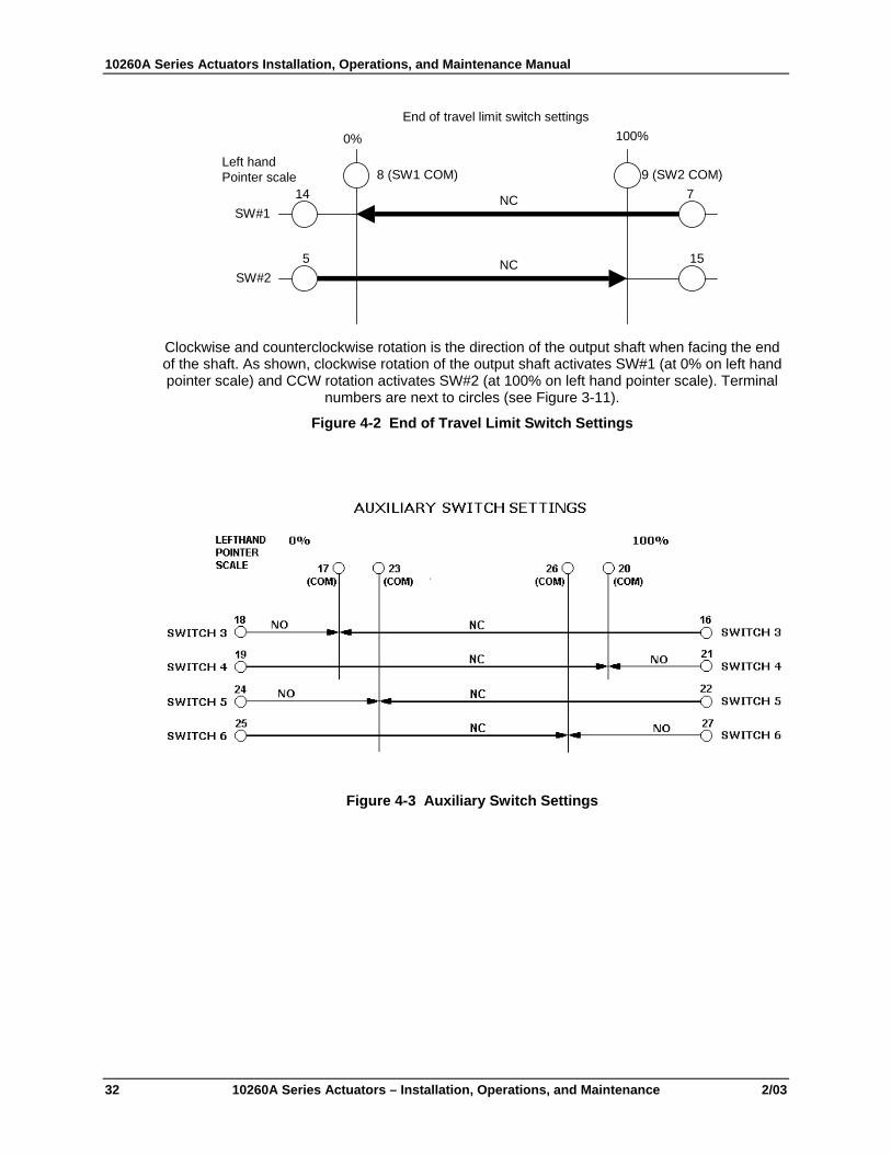
0% 100%
8 (SW1 COM) 9 (SW2 COM)7NC
NC 155
14
Left handPointer scale
SW#1
SW#2
End of travel limit switch settings
Clockwise and counterclockwise rotation is the direction of the output shaft when facing the end of the shaft. As shown, clockwise rotation of the output shaft activates SW#1 (at 0% on left hand pointer scale) and CCW rotation activates SW#2 (at 100% on left hand pointer scale). Terminal
numbers are next to circles (see Figure 3-11).
Figure 4-2 End of Travel Limit Switch Settings
Figure 4-3 Auxiliary Switch Settings

Calibration Procedures
2/03 10260A Series Actuators – Installation, Operations, and Maintenance 33
4.5 Setting Auxiliary Switches (actuators mfd. after 1/1/03) WARNING While the unit is powered, a potentially lethal shock hazard exists inside the case.
ATTENTION The first two cams (starting from the back) are for the 0 % and 100 % end of travel limit switches and should not need any adjustments as they are factory set to stop the actuator at 0 % and 100%. See Section 4.3 for setting end of travel limit switches (Switches #1 and #2). If optional auxiliary switches were ordered, these switches are not set by the factory. Switch settings should be set so that switch #3 operates in synchronism with switch #1 (i.e., both activating when the actuator is going in the same direction) and switch #4 to operates in synchronism with switch #2, etc.
To adjust the next auxiliary switch cams (see Figure 4-3): 1. Remove the terminal cover (Figure 1-1). 2. Using a slotted screwdriver on the slots at the edge of the cams, or your finger, rotate the cams until the
switches are set (see Figure 4-1). 3. The auxiliary switches should be set so switches #3 and #5 operate in synchronism with switch #1 (i.e.,
both activating when the drive is going in the same direction) and set switches #4 and #6 to operate in synchronism with switch #2.
For Switches #3 and #5: 4. Rotate the actuator shaft, using the manual handwheel or the auto/manual switch, to the desired low
scale position. 5. Rotate the #3 switch operating cam to activate at this position. The switch roller arm should go from
being in an up, not depressed state, to a depressed state as the cam is rotated in the direction of the shaft rotation going toward the limit position. This will cause the switch to go from NC to NO when the switch activates. Switch activation may be detected by the clicking sound or with a continuity tester connected to the terminals. Both the NC and NO contact states are available to the customer at the terminals (see Figure 3-11).
For Switches #4 and #6: 6. Rotate the actuator shaft, using the manual handwheel or the auto/manual switch, to the desired up
scale position. 7. Rotate the #4 switch operating cam to activate at this position. The switch roller arm should go from
being in an up, not depressed state, to a depressed state as the cam is rotated in the direction of the shaft rotation going toward the limit position. This will cause the switch to go from NC to NO when the switch activates. Both the NC and NO contact states are available to the customer at the terminals (see Figure 3-11).
8. No additional adjustments are required. 9. Double check limit switch actuation by first manually driving the actuator to each end of travel and
hearing the switch click or by detecting it with a continuity tester. Secondly, drive the actuator to both ends of travel (using the auto/manual switch or by providing minimum and full input signal) and make sure the switches activate.
Clockwise and counterclockwise rotation is the direction of the output shaft when facing the end of the shaft. As shown, clockwise rotation of the output shaft activates Switch 3 and Switch 5 similar to Limit Switch 1. Counterclockwise rotation of the output shaft activates Switch 4 and Switch 6 similar to Limit Switch 2. Terminal numbers are next to circles (see Figure 3-11).

10260A Series Actuators Installation, Operations, and Maintenance Manual
34 10260A Series Actuators – Installation, Operations, and Maintenance 2/03
4.6 Non-Contact Sensor WARNING While the unit is powered, a potentially lethal shock hazard exists inside the case.
ATTENTION The 10260A Series Actuator comes with the Non-Contact Position Sensor (NCS) already adjusted from the factory to 90 degree rotation.
If it becomes necessary to do an adjustment in the field, use the procedure given below.
1. Loosen the allen screw in the hub of the NCS spoiler just enough to be able to rotate the spoiler. (See Figure 4-4.)
2. Drive the actuator to the zero position (this refers to the position on the actuator scale for CCW rotation). This should be done manually with the hand wheel or manually with the auto/man electric switch. Next, rotate the NCS spoiler to its 0º position (it is shown in Figure 4-4 at a 45 degree angle or 10:00 o’clock zero position for CCW operating units). For CW operating units, the actuator is positioned at its 100 % position and the NCS spoiler is again at a 45 degree angle or 10:00 o’clock position. Tighten NCS spoiler set screw with allen wrench, holding spoilers in position. Spoilers need to be held in position both rotationally and longitudinally along the drive shaft extension (the gaps between each of the spoilers and the sensor circuit board should be approximately equal and any plastic or paper insulating material may be used to aid in this longitudinal positioning). Make sure that neither spoiler is touching the sensor electronics board when the adjustment is complete.
3. Connect the lead wires of a precision digital voltmeter to connector W11 pins on the 4-20 mA output card on the actuator. (The output board is positioned over the control shaft and the W11 connector is on the underside of the board just to the right of the center mounting screw). Connect the positive lead (+) to the W11 pin #2 and the negative lead (–) to pin #1.
4. Read the voltage. Voltage should be between 0.01 V and 0.02 V if the spoiler is positioned correctly.
5. If voltage is not correct, re-position the spoiler and take another voltage reading.
6. Once the voltage is within the correct range, the spoiler is in the 0° position.
7. Tighten the spoiler set screw with allen wrench.
Non-contact SensorSensing PWA
Actuator shaft extension
Non-contact sensor spoilerShown in zero position for counterclockwise operation ofthe drive.(Clockwise rotation of spoiler.)
Allen screw
Output Board
W11PIN #2+
W11W11PIN #1 -
Figure 4-4 Location of NCS Assembly

Calibration Procedures
2/03 10260A Series Actuators – Installation, Operations, and Maintenance 35
4.7 Motor Positioner Board WARNING While the unit is powered, a potentially lethal shock hazard exists inside the case.
ATTENTION The Motor Positioner board is mounted inside the top extended cover. The cover with the Motor Positioner board and cables still connecting it to the NCS Sensor and NCS board may be unscrewed from the actuator housing and positioned nearby with cables connected to make adjustments.
The Motor Positioner board has been factory calibrated for 0 % and 100 % SPAN positioning. It has also been set for default conditions given in Table 4-1.
4.7.1 Overview The Motor Positioner board provides accurate feedback control of the actuator position proportional to a 0/4 – 20 mA input signal. It also provides selectable failsafe action, input filtering and deadband sensitivity adjustment.
If the Motor Positioner option has been purchased by the user, its’ calibration is factory set, but may be adjusted as a part of the 10260A Series Actuator preliminary adjustment sequence. Once all adjustments have been made, the Motor Positioner will be fully operational.
4.7.2 Available Adjustments Operating adjustments are located on the printed circuit board accessed by removing the non-contact sensor and terminal cover. Altogether, there are two jumpers and five potentiometers with the following designations and functions:
Table 4-1 Available Adjustments Adjustment Marking Function
Jumper W1 Selects fail-safe actuator position. Selects full up or full down. Remove W1 to disable fail-safe feature. Default is “UP” position.
Jumper W2 Selects fail-safe actuator position if input signal is lost. Selects stop, or a particular position determined by R14. Remove W2 to disable fail-safe feature Default is STOP.
Potentiometer Filter, R1 Input signal filter adjustment. Default is MINIMUM.
Potentiometer Span, R7 Input signal span adjustment.
Potentiometer Zero, R11 Input signal zero adjustment.
Potentiometer Failsafe Set, R14 Adjust fail-safe position of actuator on loss of input signal. Must be enabled by W2.
Potentiometer D.U.Sens., R19 Adjusts actuator motor deadband from 1 % to 5 %. Default is ½ turn OFF maximum sensitivity. (This is ½ turn off of full CCW.)

10260A Series Actuators Installation, Operations, and Maintenance Manual
36 10260A Series Actuators – Installation, Operations, and Maintenance 2/03
4.7.3 ZERO and SPAN Adjustments WARNING While the unit is powered, a potentially lethal shock hazard exists inside the case. Do not open the case while the unit is powered. Disconnect power before moving jumpers.
REFERENCE Note that jumpers (W1 and W2) may be inserted to connect the common (center) terminal to either of two other terminals. Pull the jumper straight out from the board surfaces to remove it. To install it, align it with the desired pair of terminals and push it firmly into place.
To set the Zero and Span adjustments, use the following procedure:
1. Disconnect power.
2. Remove jumper W2 from the circuit board and set it aside for later replacement. (See Figure 4-5.)
3. Verify that limit switches and the actuator travel relative to the mechanical stops are correctly adjusted. (See Section 4.2.)
4. Make sure actuator is in CCW mode. (See Section 4.9, Step 1 only, to reverse direction.)
5. Apply power and set the input to minimum value (4 mA for 4-20 mA input, for example).
6. Adjust ZERO potentiometer (R11) until the actuator is at the desired “down” position. Pointer should point to 0 % on CCW (left) scale or 100 % on CW (right) scale.
7. Set the input to maximum value (20 mA for 4-20 mA input).
8. Adjust SPAN potentiometer (R7) until the actuator is at the desired “up” position. Pointer should point to 100 % on the CCW (left) scale or 0 % on CW (right) scale.
9. Set the input to minimum again and readjust the ZERO setting, if necessary. Repeat steps 6 through 8 until ZERO and SPAN positions are correct.
10. Disconnect power and replace jumper W2 in the desired position (refer to “Fail-safe Adjustments” in this chapter for instructions for installing W2). If CW operation is desired, reverse direction (see Section 4.9).
4.7.4 Fail-Safe Settings; Loss of Signal (L.O.S.) WARNING
!
While the unit is powered, a potentially lethal shock hazard exists inside the case. Do not open the case while the unit is powered. Disconnect power before moving jumpers.
REFERENCE Note that jumpers (W1 and W2) may be inserted to connect the common (center) terminal to either of two other terminals. Pull the jumper straight out from the board surfaces to remove it. To install it, align it with the desired pair of terminals and push it firmly into place.

Calibration Procedures
2/03 10260A Series Actuators – Installation, Operations, and Maintenance 37
Select the fail-safe setting for the event of a loss of input signal (signal from the controller to the Motor Positioner). There are two fail-safe choices, selectable by jumper W2: stop the actuator immediately, or bring the actuator to a stop at some particular position.
1. To cause the actuator to stop immediately if input signal is lost, install W2 so that it connects the center and “STOP” terminals.
2. To cause the actuator to move to a particular position if input signal is lost, place W2 so that it connects the center and “SET POS,” terminals. Then select the particular positioner that you want, as follows (you may select fully up, fully down, or any point in between).
3. With the W2 jumper installed in “SET POS” position, apply power and interrupt the input signal. The actuator will move to some random position and stop.
4. Adjust FAILSAFE SET potentiometer (R14) until the actuator is positioned at the desired fail-safe point.
To disable this fail-safe feature, remove W2.
W2 JUM PER (SHOWN IN 'ST OP' POSIT ION)
W1 JUM PER (SHOWN IN "DOWN" POSIT ION)R14
R11ZERO
R7 SPANFail-Safe SetR19
D.U.SENS.
R1 F I LT ER
Figure 4-5 Motor Positioner Board
4.7.5 Filter Settings If the input signal to the Motor Positioner contains transients or spurious signals, hunting or chattering of the actuator may occur. Use the FILTER potentiometer (R1) to smooth the input signal. Turn R1 clockwise to increase filtering.
4.7.6 Deadband and Sensitivity Settings It is sometimes desirable to introduce some amount of “deadband” between the Motor Positioner and the actuator. (Within this “deadband” zone, the actuator can be moved manually for some distance back and forth without causing a correcting signal from the Motor Positioner.)
The adjustment for “deadband” or “Actuator Sensitivity” is potentiometer R19, labeled “D.U.Sens”. Turn R19 counterclockwise to increase the amount of deadband. The adjustment can be made from 0.2 % span with R19 turned fully clockwise to 5 % with R19 turned fully counterclockwise.

10260A Series Actuators Installation, Operations, and Maintenance Manual
38 10260A Series Actuators – Installation, Operations, and Maintenance 2/03
4.8 Output Board Calibration The 10260A Series Actuator is available with one of three output boards. The first is the 0/4-20 mA Output board, the next is the Slidewire Emulation board. Finally, there is a basic NO output board that provides signal conditioning and CW/CCW reversing circuitry for the non-contact sensor. (This is used on models with 0/4-20 mA input and no output.)
4.8.1 0/4-20 mA PWA Output Board The 10260ASeries Actuator comes already calibrated from the factory. If it becomes necessary to do a calibration in the field, adjust the 4-20 mA output using the procedure below.
1. Locate the 4-20 mA output board that is positioned over the control shaft.
2. If actuator is set for CCW operation, position the actuator to 0 % span (either manually with the handwheel or auto/manual switch or for units with a Motor Positioner board, by inputting 0/4 mA input signal) and go to step 3. If actuator is set for CW operation, it will need to be set back to CCW operation to do the first step of the calibration. To set drive to CCW operation, see Section 4.9, Step 1 only. Position the actuator to 100 % of span on the right hand side scale pointer manually or with the auto/manual electric switch or for drives with a Motor Positioner board, input a 0/4 mA input signal.
3. Connect a precision voltmeter, + and – leads, to a 250 ohm shunt resistor on the 4-20 output signal terminals on the terminal block (Refer to Terminal Block Wiring diagram to locate terminals).
4. Read the voltage. The reading should be at 1 volt ± 0.75 % of span (± 0.03 volts for 1 – 5 volt output).
5. If the reading is incorrect, adjust R2 (see Figure 4-6) until the reading is in line.
6. Position the actuator to 100 % (0 % for CW pointers) of span and make another reading.
7. The voltage should read 5 volts, ± 0.75 % of span (± 0.03 volts).
8. If the reading is incorrect, adjust R1 (see Figure 4-6) until the reading comes into line.
9. You must then reposition the actuator to the 0 % (100 % for CW pointers) of span position and take another reading.
10. If the reading is out of line, repeat steps 5 through 8 until readings at both the 0 % and 100 % positions are in line.
The following additional steps are for CW units only. The adjustments that are made here will cause the actuator to reposition itself, similar to the Motor Positioner board adjustments. The actuator must be powered and must be in auto mode.
11. Set actuator back to CW operation. Switch the W10 jumper back to the 2_3 position and select “CW” on the terminal block CW/CCW switch.
12. Set the actuator to the 0 % position either manually with the handwheel or auto/manual switch or for units with a Motor Positioner board, by inputting a 0/4 mA input signal. Output should read 1 Vdc, ± 0.75 % of span (± 0.03 volts) and actuator should be positioned at 0 % span on scale.
13. If reading is incorrect or actuator in not positioned at 0 % span, adjust R3 (see Figure 4-6) until the reading is in line, and actuator is at 0 % position. Adjusting R3 will cause actuator movement (for units with a Motor Positioner board) and may be required to get actuator to 0 % position even if output is within tolerance.
14. Set the actuator to the 100 % position. Output should read 5 Vdc ± 0.75 % of span (± 0.03 volts) and actuator is at 100 % position.
15. If the reading is incorrect or position is not at 100 %, adjust R4 (see Figure 4-6) until the reading is in line, and actuator is at 100 % position.

Calibration Procedures
2/03 10260A Series Actuators – Installation, Operations, and Maintenance 39
Adjusting R4 will cause actuator movement (for units with a Motor Positioner board) and may be required to get actuator to 100 % position even if output is in tolerance.
16. Reposition the actuator to the 0 % of span position and take another reading.
17. If the reading is still out of line, repeat steps 12 through 16 until both zero and span readings and positions are in line.
R4R3
R2 R1
W10 JumperShown w ith jumper on P ins 1 and 2
for CCW Rotat ion
J5
J4
J3
J2
J1
Figure 4-6 0/4-20 mA PWA Output Board
10260A Series Actuators Installation, Operations, and Maintenance Manual
40 10260A Series Actuators – Installation, Operations, and Maintenance 2/03
4.8.2 Slidewire Emulation The Slidewire Emulation Output Card (51404886-003) can be calibrated for Slidewire Supply voltages between 1.0 Vdc and 20 Vdc. The Actuator leaves the factory with no Slidewire Supply connected to the terminals.
To calibrate the Slidewire Emulation output:
1. Remove power from the actuator, and connect the Slidewire Supply between the “H” and “L” terminals on the terminal plate. (Terminal 34 for the “L”, the low voltage side of the source and terminal 36 for the “H”, the high voltage side.) See Figure 3-11.
2. Connect a precision voltmeter, + and – leads, to terminals 35 and 34 on the terminal plate.
3. Apply the AC power to the actuator. Apply power from the Slidewire Source.
4. If actuator is set for CW operation, switch it to CCW operation. See Section 4.9, Step 1.
5. Position the actuator to the 25 % position on the CCW scale. (75 % position on CW scale.)
6. Read the voltage on the DVM. The reading should be 25 % of the Slidewire Supply ± 0.75 % of span.
7. If the reading is incorrect, adjust R5 until the reading is within tolerance.
8. Position the actuator to the 75 % position on the CCW scale. (25 % position on the CW scale.)
9. Read the voltage on the DVM. The reading should be 75 % of the Slidewire Supply, ± 0.75 % of span.
10. If the reading is incorrect adjust R59 until the reading comes into line.
11. Repeat steps 4 through 9 until the readings are within tolerance.
12. If CW operation is desired, switch actuator back to CW operation by following Section 4.9.

Calibration Procedures
2/03 10260A Series Actuators – Installation, Operations, and Maintenance 41
J7
J6
J5
J4
J3
R59R5
Figure 4-7 Slidewire Emulation Board

10260A Series Actuators Installation, Operations, and Maintenance Manual
42 10260A Series Actuators – Installation, Operations, and Maintenance 2/03
4.9 Reversal of Direction (Non contact sensor) The CW/CCW Inverter Output Circuit is included on each of the versions of the NCS Output Card (51404886-001, 002, and 003). It can be calibrated by monitoring any of the output signals or using the scale on the actuator. For this procedure it is assumed that the pointer is set on the CW scale. (If the pointer is not changed to the CW scale replace 0 % with 100 % in this write up and 100 % with 0 %). The Actuator leaves the factory configured for CCW rotation. (Actuator should be calibrated for both CW and CCW operation and should not require recalibration when reversing direction.)
To change to CW rotation:
1. Remove power from the actuator, and change the jumper on W10 (see Figure 4-8) from the pin 1 to 2 position to the 2 to 3 position. Also place the toggle switch on the terminal block plate to the CW side.
2. Connect a precision voltmeter, + and – leads, to the output terminals or read the output on the scale of the actuator.
3. Apply the AC power to the actuator.
4. Set the input to the actuator to the 25 % point.
5. Read the voltage on the DVM or the scale position. The reading should be 25 % of the output span ± 0.75 % of span.
6. If the reading is incorrect, adjust R3 (see Figure 4-6) until the reading is within tolerance.
7. Set the input to the actuator to the 75 % point.
8. Read the voltage on the DVM or the actuator scale. The reading should be 75 % of the span, ± 0.75 % of span.
9. If the reading is incorrect adjust R4 (see Figure 4-6) until the reading comes into line.
10. Repeat steps 4 through 9 until the readings are within tolerance.
4.10 Reversal of Direction (Film Potentiometer) The actuator leaves the factory configured for counterclockwise rotation.
To change to clockwise rotation:
1. Remove power from the actuator, and interchange the black lead with the yellow lead at terminals 35 and 37. Place the toggle switch on the terminal block plate to the CW side.
2. Move the pointer from the Left-hand scale to the Right-hand scale.
3. Apply the AC power to the actuator.
4. Set the input to the actuator to the 25% point.
5. The scale position should be 25% of the output range +/-0.75% of span.
6. If the reading is incorrect, adjust R3 (see Figure 4-6) until reading is within tolerance.
7. Set the input to the actuator to the 75% point.
8. The scale position should be 75% of the output range +/-0.75% of span.
9. If the reading is incorrect, adjust R4 (see Figure 4-6) until reading is within tolerance.
10. Repeat steps 4 through 9 until the readings are within tolerance.

Calibration Procedures
2/03 10260A Series Actuators – Installation, Operations, and Maintenance 43
ccw
SC ALE 1 .500
cw
SC ALE 1.500
T E RM IN AL B LO CK P LA T E
T O GG LE HA ND L E T O RI GH TCC W PO S I T I O N
W1 0SH O W N I N
CC W PO S I T I O N
PR IN T EDCI R C UI TBO A RD
Figure 4-8 Switch Jumper for Reversal

10260A Series Actuators Installation, Operations, and Maintenance Manual
44 10260A Series Actuators – Installation, Operations, and Maintenance 2/03

Start-up/Operation
2/03 10260A Series Actuators – Installation, Operations, and Maintenance 45
5. Start-Up/Operation
5.1 Introduction After the equipment is completely installed, wired, and the preliminary adjustment made, it is advisable to check the operation of the actuator and controlled device before using the equipment for actual control. In other words, operate the controlled device and check its direction of travel in response to an increase in the controlled variable and make sure it is correct for the process. Actuators having the optional Auto-Manual Switch must have the knob in the AUTO position.
This chapter provides a checklist which can be used to do a walk-through with the actuator before it is actually used for control.
5.2 Operations Checklist 1. Refer to customer's connection diagram supplied with each actuator to determine direction of actuator
rotation.
2. If the process being controlled requires opposite actuator rotation from that supplied by the factory, this may be accomplished by following the field reversal procedure in Section 4.9.
3. To check the operation of the optional Auto-Manual Switch, move the knob to the C. W. and C.C. W. MANUAL: positions. The output shaft should rotate in the direction indicated by the knob.

10260A Series Actuators Installation, Operations, and Maintenance Manual
46 10260A Series Actuators – Installation, Operations, and Maintenance 2/03

Other Control Functions
2/03 10260A Series Actuators – Installation, Operations, and Maintenance 47
6. Other Control Functions
6.1 Split Range WARNING While the unit is powered, a potentially lethal shock hazard exists inside the case.
Procedure for Actuator to Operate from 4 to 12 mA
To set span of printed circuit board to 8 mA:
• Set input to 0 mA and adjust Zero pot on printed circuit board to 0 % on actuator scale.
• Set input to 8 mA and adjust Span pot on printed circuit board to 100 % on actuator scale.
To set actuator to operate at 4 to 12 mA:
• Set input to 4 mA and adjust Zero pot on printed circuit board to 0 % on actuator scale.
• Set input to 12 mA and verify span at 100 % on actuator scale. No adjustment should be necessary.
• Replace Jumpers on printed circuit board.
Procedure for Actuator to Operate from 12 to 20 mA
To set span of printed circuit board to 8 mA:
• Set input to 0 mA and adjust Zero pot on printed circuit board to 0 % on actuator scale.
• Set input to 8 mA and adjust Span pot on printed circuit board to 100 % on actuator scale.
To set actuator to operate at 12 to 20 mA:
• Set input to 12 mA and adjust Zero pot on printed circuit board to 0 % on actuator scale.
• Set input to 20 mA and verify span at 100 % on actuator scale. No adjustment should be necessary.
Replace Jumpers on printed circuit board.
6.2 Master/Slave Arrangement
Introduction With the motor positioner, the controlling signal for the actuator is a 4 to 20mA from a current output controller.
Unlike the position output controller the current output controller must produce a continuous analog signal or the actuator will revert to one of its failure modes. These are customer selected by movable jumper to remain where it is, downscale, upscale or to a predetermined position (adjustable).
Signal failure is not a problem since the available failure modes allow the user to predict the actuator position on signal loss.

10260A Series Actuators Installation, Operations, and Maintenance Manual
48 10260A Series Actuators – Installation, Operations, and Maintenance 2/03
6.2.1 Basic Flow Control When the process variable signal is below set point, the current output increases (4 to 20mA) opening the valve.
At 4mA the zero adjustment on the motor positioner PCA is made for the low end of actuator travel.
At 20mA the span adjustment is used for the high end of actuator travel. The graph shows the linear relationship.
The adjustment pots are located on the PCA. The slidewire/switch housing cover on the actuator must be removed for access to all adjustments including the signal filter and deadband pots.
Controller set point governs valve position to obtain desired flow rate.
Figure 6-1 Flow Diagram
Figure 6-2 Interconnection Diagram
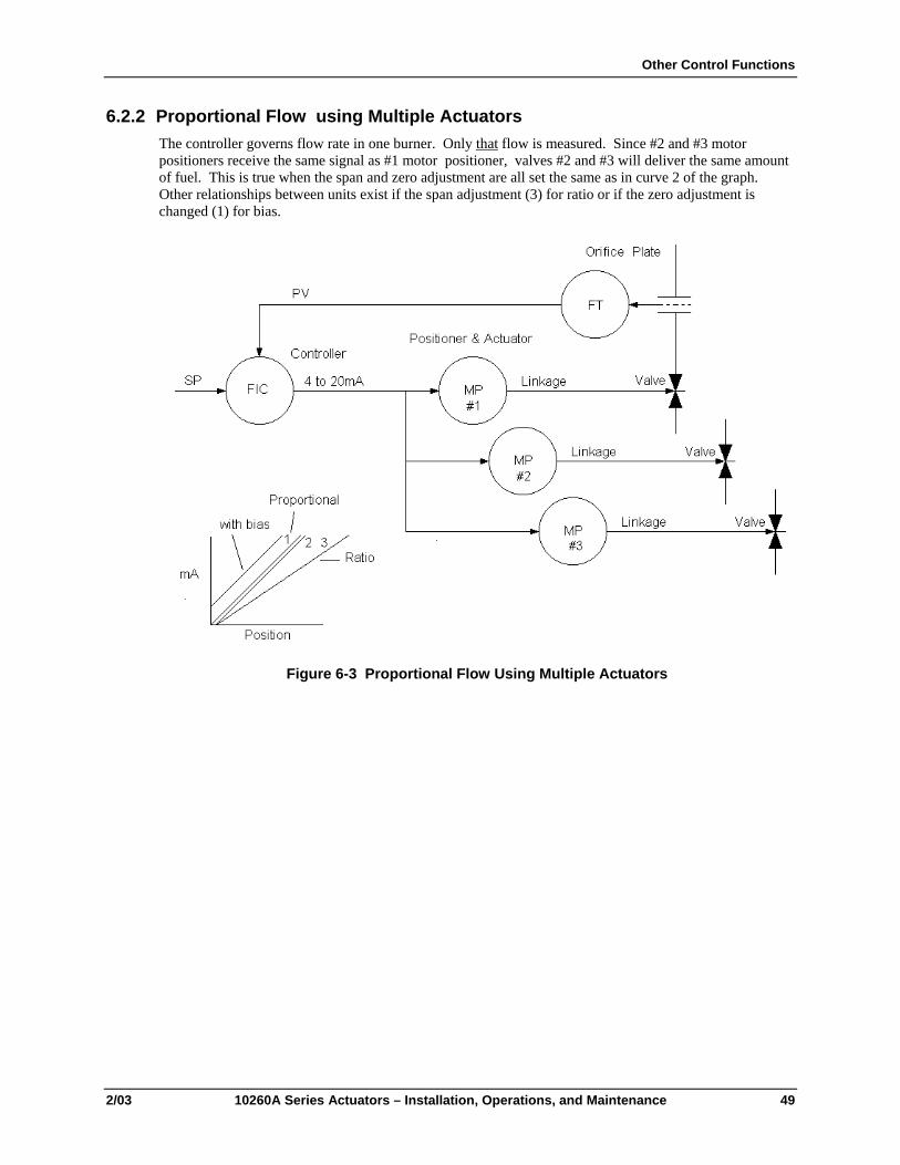
Other Control Functions
2/03 10260A Series Actuators – Installation, Operations, and Maintenance 49
6.2.2 Proportional Flow using Multiple Actuators The controller governs flow rate in one burner. Only that flow is measured. Since #2 and #3 motor positioners receive the same signal as #1 motor positioner, valves #2 and #3 will deliver the same amount of fuel. This is true when the span and zero adjustment are all set the same as in curve 2 of the graph. Other relationships between units exist if the span adjustment (3) for ratio or if the zero adjustment is changed (1) for bias.
Figure 6-3 Proportional Flow Using Multiple Actuators

10260A Series Actuators Installation, Operations, and Maintenance Manual
50 10260A Series Actuators – Installation, Operations, and Maintenance 2/03
Figure 6-4 Multiple Actuator Interconnection Diagram
REFERENCE The minimum recommended “zero” adjustment is 0.2 V. Below 0.11 V the positioner assumes a loss of signal and will drive the actuator to the customer selected position. The maximum zero adjustment is 3.0 V if full travel is desired (span set at 5.0 V). Minimum span setting is 1.0 V, maximum span setting is 5.0 V. To insure failsafe action, in the event that the input is disconnected, a 10 K-ohm bleeder resistor should be placed across the input terminals.

Other Control Functions
2/03 10260A Series Actuators – Installation, Operations, and Maintenance 51
6.2.3 Split Valve Configuration A common heat or cool type process requires two valves. In this case the controller has only one output. The two motor positioners are calibrated differently, one responds to 4 mA to 12 mA and the other responds to 12 mA to 20 mA. At 12 mA both valves are closed, one opening below 12 mA and the other above 12 mA. It is also easy to have deadband in the center where both valves are closed, or overlap where both are open. Deadband is obtained with the zero and span adjustments on the motor positioner PCA.
Figure 6-5 Interconnection Diagram

10260A Series Actuators Installation, Operations, and Maintenance Manual
52 10260A Series Actuators – Installation, Operations, and Maintenance 2/03

Maintenance
2/03 10260A Series Actuators – Installation, Operations, and Maintenance 53
7. Maintenance
7.1 Introduction There is some basic maintenance that is recommended for the 10260A Series Actuators. The Non-contact Sensor, Motor Positioner, Slidewire Emulator, and 4-20 Output Board require no maintenance or servicing under normal conditions.
If there is a problem, this chapter provides the user with the information needed to return the 10260ASeries Actuator to peak performance.
7.2 Basic Maintenance
7.2.1 Main Gear Lubrication The main gears are lubricated at the factory with Texaco Starplex 2 EP grease. Honeywell recommends visual inspection of the worm and worm gear lubricant during major shutdown periods. Apply lubricant as necessary to assure that the gears are adequately protected.
To perform the inspection, first loosen the side control compartment cover fasteners and then remove the top cover plate. After the inspection, check the gaskets for damage and replace if necessary. Re-install the top cover first and then tighten the side control cover fasteners.
7.2.2 Spur Gear Lubrication Honeywell recommends during major shutdown periods that the gear cover be removed and spur gears inspected and lubricated by apply a coating of Texaco Starplex 2 EP grease or equivalent.
7.2.3 Non-Contact Sensor There is no maintenance required.
7.2.4 Motor Positioner There is no maintenance required.
7.2.5 Replacing the Fuses
WARNING
!
Disconnect power before opening the instrument case to replace the fuse(s). A potentially lethal shock hazard exists inside the case if the unit is opened while powered.

10260A Series Actuators Installation, Operations, and Maintenance Manual
54 10260A Series Actuators – Installation, Operations, and Maintenance 2/03

Replacement/Recommended Spare Parts
2/03 10260A Series Actuators – Installation, Operations, and Maintenance 55
8. Replacement/Recommended Spare Parts
8.1 Introduction This chapter provides the user with a complete list of all the spare parts that may be needed for the 10260A Series Actuators and the optional equipment.
8.2 Motor Kits Kit #51205551-501 Motor 1026 (1, 2, 4, 6) 120 V 50/60 Kit
Part Description Quantity
MOTOR 1
CAPACITOR, MOTOR 7.5uf 1
GASKET KIT (10260) 1
INSTRUCTIONS, MOTOR 1
Kit #51205551-502 Motor 10263 120 V 50/60 Kit
Part Description Quantity
MOTOR 1
CAPACITOR, MOTOR 11uf - 60 HZ 1
CAPACITOR, MOTOR 13uf - 50 HZ 1
GASKET KIT (10260) 1
INSTRUCTIONS, MOTOR 1
Kit #51205551-503 Motor 1026 (7, 8, 9) 120 V 50/60 Kit
Part Description Quantity
MOTOR 1
CAPACITOR, MOTOR 14uf 1
INSTRUCTIONS, MOTOR 1
GASKET KIT (10260) 1

10260A Series Actuators Installation, Operations, and Maintenance Manual
56 10260A Series Actuators – Installation, Operations, and Maintenance 2/03
Kit #51205551-504 Motor 1026 (1, 2, 4, 6, 7, 8, 9) 240 V 50/60 Kit
Part Description Quantity
MOTOR 1
CAPACITOR, MOTOR 1
CAPACITOR, MOTOR 1
GASKET KIT (10260) 1
INSTRUCTIONS, MOTOR 1
Kit #51205551-505 Motor 10263 240 V 50/60 Kit
Part Description Quantity
MOTOR 1
CAPACITOR, MOTOR 1
CAPACITOR, MOTOR 1
GASKET KIT (10260) 1
INSTRUCTIONS, MOTOR 1
Kit #51205551-506 Motor 10265 120 V 50/60 Kit
Part Description Quantity
MOTOR 1
CAPACITOR, MOTOR 11uf - 60 HZ 1
CAPACITOR, MOTOR 13uf - 50 HZ 1
GASKET KIT (10260) 1
INSTRUCTIONS, MOTOR 1
Kit #51205551-507 Motor 10265 240 V 50/60 Kit
Part Description Quantity
MOTOR 1
CAPACITOR, MOTOR 1
CAPACITOR, MOTOR 1
GASKET KIT (10260) 1
INSTRUCTIONS, MOTOR 1

Replacement/Recommended Spare Parts
2/03 10260A Series Actuators – Installation, Operations, and Maintenance 57
8.3 Idler Gear Kits Kit #51205552-501 Idler Gear 1026 (1, 2, 4, 6, 7) Fiber (2) Kit
Part Description Quantity
IDLER GEAR ASSY (FIBER) 2
GASKET KIT (10260) 1
INSTRUCTIONS, IDLER GEAR 1
Kit #51205552-502 Idler Gear 1026 (8, 9) Steel (2) Kit
Part Description Quantity
IDLER GEAR ASSY (STEEL) 2
GASKET KIT (10260) 1
INSTRUCTIONS, IDLER GEAR 1
Kit #51205552-503 Idler Gear 1026 (3, 5) Steel (2) Kit
Part Description Quantity
IDLER GEAR ASSY (STEEL) 1
GASKET KIT (10260) 1
INSTRUCTIONS, IDLER GEAR 1
8.4 Non-Contact Sensor, Film Potentiometer, Output Board Limit/Aux Switch and CAM Kits Kit #51404926-501 Non-Contact Sensor (NCS) Replacement
Part Description Quantity
NCS 1
GAGE, SENSOR ALIGNMENT 1
SCREWS, #4-40 X 5/16 4
LOCKWASHER, #4 4
INSTRUCTIONS NCS 1
GASKET KIT (10260) 1

10260A Series Actuators Installation, Operations, and Maintenance Manual
58 10260A Series Actuators – Installation, Operations, and Maintenance 2/03
Kit #51451656-507 Film Potentiometer Kit
Part Description Quantity
FILM POTENTIOMETER 1000 OHMS, 90 DEGREES 1
GASKET SET FOR 1 1026X UNIT 1
1026XA WIRING DIAGRAM FILM POTENTIOMETER 1
Kit #51404885-501 Power Inverter/NCS Board
Part Description Quantity
POWER INVERTER/NCS PWA 1
GASKET KIT (10260) 1
SCREW, #6-32 X 3/8 4
LOCKWASHER, #6 4
INSTRUCTIONS, INVERTER 1
Kit #51404885-502 4-20 Output Board
Part Description Quantity
4-20 OUTPUT BOARD 1
GASKET KIT (10260) 1
SCREW, #6-32 X 3/8 4
LOCKWASHER, #6 4
INSTRUCTIONS, 4-20 OUTPUT 1
Kit #51404885-503 Slidewire Emulator Board
Part Description Quantity
SLIDEWIRE EMULATOR BOARD 1
GASKET KIT (10260) 1
SCREW, #6-32 X 3/8 4
LOCKWASHER, #6 4
INSTRUCTIONS, SLIDEWIRE EMULATION 1

Replacement/Recommended Spare Parts
2/03 10260A Series Actuators – Installation, Operations, and Maintenance 59
Kit #51404978-501 4-20 mA Input (CAT/PAT) Board (120V)
Part Description Quantity
CAT/PAT (120V) 1
GASKET KIT (10260) 1
30 OHM RESISTOR KIT 1
INSTRUCTIONS, CAT/PAT 1
Kit #51404978-502 4-20 mA Input (CAT/PAT) Board (240 V)
Part Description Quantity
CAT/PAT KIT (240V) 1
GASKET KIT (10260) 1
30 OHM RESISTOR KIT 1
INSTRUCTIONS, CAT/PAT 1
Kit #51404978-503 4-20 mA Input (CAT/PAT) Board with Cables (120 V)
Part Description Quantity
CAT/PAT PWA KIT (120V) 1
CABLE ASSY, INPUT CAT/PAT 1
CABLE ASSY, POWER IN/ MOTOR OP 1
Kit #51404978-504 4-20 mA Input (CAT/PAT) Board with Cables (240 V)
Part Description Quantity
CAT/PAT PWA KIT (120V) 1
CABLE ASSY, INPUT CAT/PAT 1
CABLE ASSY, POWER IN/ MOTOR OP 1
Kit #51309623-502 Auto/Manual Switch Kit
Part Description Quantity
AUTO/MANUAL SWITCH ASSY(10260A) 1
LABEL 2
KNOB 3
INSTRUCTIONS, AUTO/MANUAL 4
GASKET KIT (10260) 1

10260A Series Actuators Installation, Operations, and Maintenance Manual
60 10260A Series Actuators – Installation, Operations, and Maintenance 2/03
Kit #51205550-501 Switch Kit
Part Description Quantity
SWITCH BRACKET 1
SCREWS, #10-32 X 1/2 3
LOCKWASHER, #10 3
WASHER (N) #10 3
SWITCH SUPPORT BRACKET 1
SWITCHES 6
SWITCH INSULATOR 2
SCREW, #4-40 X .75 4
LOCKWASHER, #4 4
WASHER (N) #4 4
SCREW, #4-40 X 1.25 4
SCREW, #4-40 X 1.75 4
CABLE ASSY, SWITCH 3
INSTRUCTIONS, SWITCH KIT 1
GASKET KIT (10260) 1
Note: Cam kit 51205553-501 also required if adding switches
Kit #51205553-501 Cam Assembly Kit
Part Description Quantity
BUSHING, CAM 1
SCREW, SOC SET #10-32 X 1/4 2
LOCKING NUT 1
WASHER, TOOTHED 6
WASHER, CAM 5
SPACER, CAM 3
CAM 5
INSTRUCTIONS, CAM 1

Replacement/Recommended Spare Parts
2/03 10260A Series Actuators – Installation, Operations, and Maintenance 61
8.5 Linkage Parts/Kits Turnbuckle Kit Pipe Kit
Overall linkage length (inches/cm) Overall linkage length (inches/cm)*
min. max. kit number min. max. pipe size kit number
12 16 083381 24 72 1” 083384
16 20 083382 24 120 1 ½” 083385
up to 75 lb-ft (100 NM)
20 24 083383 - - - -
Overall linkage length (inches) Overall linkage length (inches)*
min. max. kit number min. max. pipe size kit number
12 16 083381 24 28 1” 083384
16 20 083382 24 84 1 ½” 083385
150 to 300 lb-ft (200 to 410 NM)
20 24 083383 24 120 2” 083386
8.6 Accessories Part Number
5” Crankarm kit 51309967-501
12” Crankarm kit 51452160-501
HAL Software 51197910-001
Gasket kit
Transformer 51404947-501
250 ohm resistor 070756

10260A Series Actuators Installation, Operations, and Maintenance Manual
62 10260A Series Actuators – Installation, Operations, and Maintenance 2/03
8.7 Non-Contact Position Sensor Field Upgrade Kits NOTE:These kits are for upgrading 10260A Actuators. Kits for upgrading existing 10260 Actuators are covered separately.
Kit #51205568-501 NCS 4-20 mA Input and 4-20 mA Output Upgrade Kit (120 V)
Part Description Quantity
NC SENSOR PWA KIT 1
4-20OP INVERTER/RVIT-Z PWA 1
CAT/PAT 4-20 INPUT W/CABLES (120 V) 1
NCS BRACKET 1
SCREWS, #10-32 X 3/4 4
LOCKWASHER, #10 4
WASHER (N) #10 4
FRAME, PWA 1
SCREW, #10-32 X 1/2 1
INSTRUCTIONS, NCS UPGRADE W/4-20 OP 1
CABLES, NCS POWER 1
CABLES, POWER IP/MOTOR OP 1
CABLE, 4-20 IP 1
Kit #51205568-502 NCS 4-20 mA Input and 4-20 mA Output Upgrade Kit (240 V)
Part Description Quantity
NC SENSOR PWA KIT 1
4-20OP INVERTER/RVIT-Z PWA 1
CAT/PAT 4-20 INPUT W/CABLES (240 V) 1
NCS BRACKET 1
SCREWS, #10-32 X 3/4 4
LOCKWASHER, #10 4
WASHER (N) #10 4
FRAME, PWA 1
SCREW, #10-32 X 1/2 1
INSTRUCTIONS, NCS UPGRADE W/4-20 OP 1
CABLES, NCS POWER 1
CABLES, POWER IP/MOTOR OP 1
CABLE, 4-20 IP 1
CABLE, 4-20 OP 1
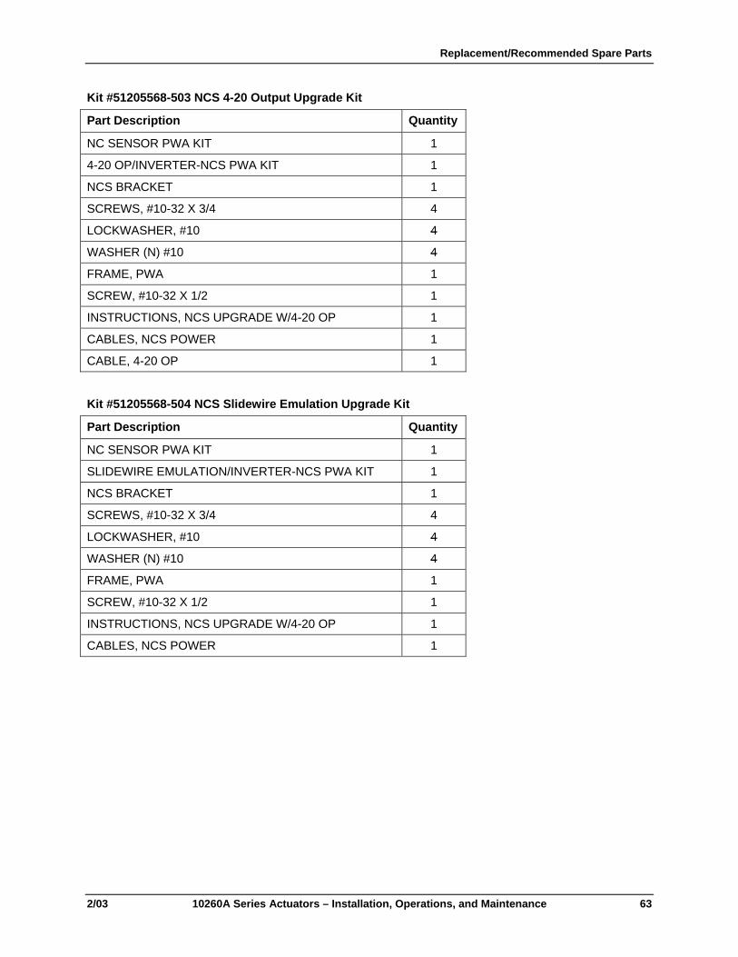
Replacement/Recommended Spare Parts
2/03 10260A Series Actuators – Installation, Operations, and Maintenance 63
Kit #51205568-503 NCS 4-20 Output Upgrade Kit
Part Description Quantity
NC SENSOR PWA KIT 1
4-20 OP/INVERTER-NCS PWA KIT 1
NCS BRACKET 1
SCREWS, #10-32 X 3/4 4
LOCKWASHER, #10 4
WASHER (N) #10 4
FRAME, PWA 1
SCREW, #10-32 X 1/2 1
INSTRUCTIONS, NCS UPGRADE W/4-20 OP 1
CABLES, NCS POWER 1
CABLE, 4-20 OP 1
Kit #51205568-504 NCS Slidewire Emulation Upgrade Kit
Part Description Quantity
NC SENSOR PWA KIT 1
SLIDEWIRE EMULATION/INVERTER-NCS PWA KIT 1
NCS BRACKET 1
SCREWS, #10-32 X 3/4 4
LOCKWASHER, #10 4
WASHER (N) #10 4
FRAME, PWA 1
SCREW, #10-32 X 1/2 1
INSTRUCTIONS, NCS UPGRADE W/4-20 OP 1
CABLES, NCS POWER 1

10260A Series Actuators Installation, Operations, and Maintenance Manual
64 10260A Series Actuators – Installation, Operations, and Maintenance 2/03
Kit #51205568-505 NCS 4-20 mA Input Upgrade Kit (120 V)
Part Description Quantity
NC SENSOR PWA KIT 1
POWER INVERTER/RVIT-Z PWA 1
CAT/PAT 4-20 INPUT W/CABLES (120 V) 1
NCS BRACKET 1
SCREWS, #10-32 X 3/4 4
LOCKWASHER, #10 4
WASHER (N) #10 4
FRAME, PWA 1
SCREW, #10-32 X 1/2 1
INSTRUCTIONS, NCS UPGRADE W/4-20 OP 1
CABLES, NCS POWER 1
CABLES, POWER IP/MOTOR OP 1
CABLE, 4-20 IP 1
Kit #51205568-506 NCS 4-20 mA Input Upgrade Kit (240 V)
Part Description Quantity
NC SENSOR PWA KIT 1
POWER INVERTER/RVIT-Z PWA 1
CAT/PAT 4-20 INPUT W/CABLES (240 V) 1
NCS BRACKET 1
SCREWS, #10-32 X 3/4 4
LOCKWASHER, #10 4
WASHER (N) #10 4
FRAME, PWA 1
SCREW, #10-32 X 1/2 1
INSTRUCTIONS, NCS UPGRADE W/4-20 OP 1
CABLES, NCS POWER 1
CABLES, POWER IP/MOTOR OP 1
CABLE, 4-20 IP 1

Replacement/Recommended Spare Parts
2/03 10260A Series Actuators – Installation, Operations, and Maintenance 65
8.8 Honeywell Actuator Linkage Analysis Software (HAL) Part Number: 51197910-001
8.9 Replacement Fuses (Not for Sale) Bussmann GDB1.6: 1.6 Amp Fast Littlefuse 312001: 1.0 Amp Fast
8.10 Film Potentiometer Upgrade Kits
Kit #51205568-507 Film Potentiometer Upgrade Kit
Part Description Quantity
HEX STANDOFF 1
NCS BRACKET 1
MOUNTING PLATE - POTENTIOMETER 1
SEMS #4-40 X .310LG PNPHSTL 2
SEMS-EXT 8-32 X .50 PHPNSS 1
SEMS-EXT 10-32 X .75 PHPNSS 4
WIRE CAP 1
6-32 NUT WASHER ASSY 2
POT, 1K, DUAL ELEMENT, 90 DEG 1
POT ACTUATOR 10260A 1
SET SCREW 3/32 X 3-48 10260A 1
RESISTOR 110 OHMS 1% 1/2W 1
RESISTOR 158 OHMS 1% 1/2W 1
1026XA Wiring Diagram Film Potentiometer 1
Gasket set for 1 1026X Unit 1

10260A Series Actuators Installation, Operations, and Maintenance Manual
66 10260A Series Actuators – Installation, Operations, and Maintenance 2/03
Kit #51205568-508 Film Pot, 4 to 20mA Input 120VAC Upgrade Kit
Part Description Quantity
HEX STANDOFF 1
8-32 NUT WASHER ASSY 2
THDFRMPANSCAD1/4X6-32 TAPTITE 4
NCS BRACKET 1
CAT/PAT INPUT CAB ASSY 10260A 1
MOUNTING PLATE - POTENTIOMETER 1
-OHM 30. 30. W 5% 1
4-20 IP CAT/PAT 120V (10260A) 1
SEMS #4-40 X .310LG PNPHSTL 2
SEMS-EXT 8-32 X .50 PHPNSS 1
SEMS-EXT 10-32 X .75 PHPNSS 4
WIRE CAP 1
RESISTOR-SHUNT 1
6-32 NUT WASHER ASSY 2
POT, 1K, DUAL ELEMENT, 90 DEG 1
POT ACTUATOR 10260A 1
SET SCREW 3/32 X 3-48 10260A 1
RESISTOR 110 OHMS 1% 1/2W 1
RESISTOR 158 OHMS 1% 1/2W 1
1026XA Wiring Diagram Film Potentiometer 1
Gasket set for 1 1026X Unit 1

Replacement/Recommended Spare Parts
2/03 10260A Series Actuators – Installation, Operations, and Maintenance 67
Kit #51205568-509 Film Pot, 4 to 20mA Input 240VAC Upgrade Kit
Part Description Quantity
HEX STANDOFF 1
8-32 NUT WASHER ASSY 2
THDFRMPANSCAD1/4X6-32 TAPTITE 4
NCS BRACKET 1
CAT/PAT INPUT CAB ASSY 10260A 1
MOUNTING PLATE - POTENTIOMETER 1
-OHM 30. 30. W 5% 1
4-20 IP CAT/PAT 240V (10260A) 1
SEMS #4-40 X .310LG PNPHSTL 2
SEMS-EXT 8-32 X .50 PHPNSS 1
SEMS-EXT 10-32 X .75 PHPNSS 4
WIRE CAP 1
RESISTOR-SHUNT 1
6-32 NUT WASHER ASSY 2
POT, 1K, DUAL ELEMENT, 90 DEG 1
POT ACTUATOR 10260A 1
SET SCREW 3/32 X 3-48 10260A 1
RESISTOR 110 OHMS 1% 1/2W 1
RESISTOR 158 OHMS 1% 1/2W 1
1026XA Wiring Diagram Film Potentiometer 1
Gasket set for 1 1026X Unit 1

10260A Series Actuators Installation, Operations, and Maintenance Manual
68 10260A Series Actuators – Installation, Operations, and Maintenance 2/03
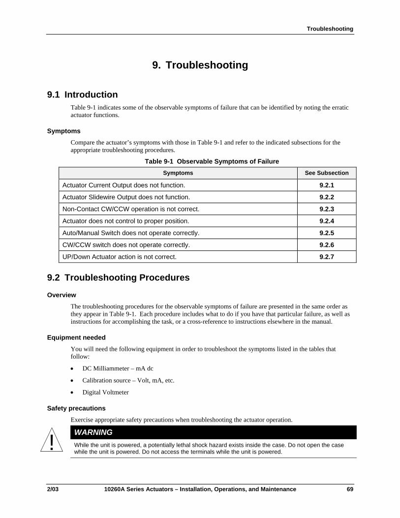
Troubleshooting
2/03 10260A Series Actuators – Installation, Operations, and Maintenance 69
9. Troubleshooting
9.1 Introduction Table 9-1 indicates some of the observable symptoms of failure that can be identified by noting the erratic actuator functions.
Symptoms Compare the actuator’s symptoms with those in Table 9-1 and refer to the indicated subsections for the appropriate troubleshooting procedures.
Table 9-1 Observable Symptoms of Failure Symptoms See Subsection
Actuator Current Output does not function. 9.2.1
Actuator Slidewire Output does not function. 9.2.2
Non-Contact CW/CCW operation is not correct. 9.2.3
Actuator does not control to proper position. 9.2.4
Auto/Manual Switch does not operate correctly. 9.2.5
CW/CCW switch does not operate correctly. 9.2.6
UP/Down Actuator action is not correct. 9.2.7
9.2 Troubleshooting Procedures
Overview The troubleshooting procedures for the observable symptoms of failure are presented in the same order as they appear in Table 9-1. Each procedure includes what to do if you have that particular failure, as well as instructions for accomplishing the task, or a cross-reference to instructions elsewhere in the manual.
Equipment needed
You will need the following equipment in order to troubleshoot the symptoms listed in the tables that follow:
• DC Milliammeter – mA dc
• Calibration source – Volt, mA, etc.
• Digital Voltmeter
Safety precautions
Exercise appropriate safety precautions when troubleshooting the actuator operation.
WARNING
!
While the unit is powered, a potentially lethal shock hazard exists inside the case. Do not open the case while the unit is powered. Do not access the terminals while the unit is powered.

10260A Series Actuators Installation, Operations, and Maintenance Manual
70 10260A Series Actuators – Installation, Operations, and Maintenance 2/03
9.2.1 Actuator Current Output does not function. Table 9-2 explains how to troubleshoot the actuator current output failure.
Table 9-2 Troubleshooting Current Output Step What to Do How To Do it or Where to Find the Instructions
1 Check that the cables are plugged into the correct headers on the NCS Output Board.
On the NCS Output Board insure that the following are connected: (See Figure 4-6.)
J5 – BRN, BRN, YEL;
J2 – BLU, BLU, VIO;
J3 – RED, GRN, WHT;
J1 – GRY, YEL
J4 – ORN, YEL (If Motor Positioner board present)
2 Check that a load resistor is connected to the output.
After removing the GRY and YEL wires from TB-32 and 33, measure, using an ohmmeter, the load resistor to verify it is connected between terminals TB-32 and 33. See Figure 3-11.
3 Check the input signal to the NCS Output Board.
Using a DVM measure the voltage between the pins on W11. The voltage should be in the range of 0 Vdc to 1.25 Vdc. See Figure 4-4.
4 Check/Recalibrate. Refer to Section 4 to check calibration and to recalibrate. First check Section 4.6 for proper positioning and calibration of non-contact sensor.
5 Replace the NCS Output Board. Refer to the replacement procedure in Section 8 – Replacement/Recommended Spare Parts.

Troubleshooting
2/03 10260A Series Actuators – Installation, Operations, and Maintenance 71
9.2.2 Actuator Slidewire Output does not function. Table 9-3 explains how to troubleshoot the actuator Slidewire Output failure.
Table 9-3 Troubleshooting Slidewire Output Step What to Do How To Do it or Where to Find the Instructions
1 Check that the cables are plugged into the correct headers on the NCS Output Board.
On the NCS Output Board insure that the following are connected: (See Figure 4-7.)
J5 – BRN, BRN, YEL;
J7 – ORN, ORN, GRY;
J3 – RED, GRN, WHT:
J6 – RED, YEL, BLU.
J4 – ORN, YEL (If Motor Positioner board is present.)
2 Check that the external controller is supplying a slidewire voltage supply.
Using the Digital Voltmeter measure the voltage from pin 34 to pin 36 on TB. This voltage should be in the range of 1.000 Vdc to 20 Vdc. See Figure 3-11.
3 Check the input signal to the NCS Output Board.
Using a DVM measure the voltage between the pins on W11. The voltage should be in the range of 0 to 1.25 Vdc. See Figure 4-4.
4 Check/Recalibrate. Refer to Section 4 to check calibration and to recalibrate. First check Section 4.6 for proper positioning and calibration of non-contact sensor.
5 Replace the NCS Output Board. Refer to the replacement procedure in Section 8 – Replacement/Recommended Spare Parts.

10260A Series Actuators Installation, Operations, and Maintenance Manual
72 10260A Series Actuators – Installation, Operations, and Maintenance 2/03
9.2.3 Actuator CW/CCW operation is not correct. Table 9-4 explains how to troubleshoot the actuator for proper CW/CCW operation.
Table 9-4 Troubleshooting CW/CCW Operation Step What to Do How To Do it or Where to Find the Instructions
1 Check that the cables are plugged into the correct headers on the NCS Output Board.
On the NCS Output Board insure that the following are connected: (See Figure 4-6.)
J5 – BRN, BRN, YEL
J3 – RED, GRN, WHT
W10 – jumper pins 1 to 2 – CCW
W10 – jumper pins 2 to 3 – CW
J4 – ORN, YEL (If Motor Positioner board is present.)
2 Check that the shaft turns correctly for CCW drive.
If actuator is used in CCW direction and input is increasing measure, using a DVM, the voltage at W11 See Figure 4-4. It should be increasing from 0 Vdc to 1.25 Vdc as input increases and shaft rotates CCW. If this is not the case go back to STEP 1 and check W10 jumper position. See Figure 4-6.
3 Check that shaft turns correctly for CW drive
If actuator is used in CW direction and input is increasing measure, using a DVM, the voltage at W11. See Figure 4-4. It should be decreasing from 1.25 Vdc to 0 Vdc as input increases and shaft rotates CW. If this is not the case go back to STEP 1 and check W10 jumper position. See Figure 4-6.
4 Check/Recalibrate. Refer to Section 4 to check calibration and to recalibrate. First check Section 4.6 for proper positioning and calibration of non-contact sensor.
5 Replace the NCS Output Board.
Refer to the replacement procedure in Section 8 – Replacement/Recommended Spare Parts.

Troubleshooting
2/03 10260A Series Actuators – Installation, Operations, and Maintenance 73
9.2.4 Actuator does not control to the proper position. Table 9-5 explains how to troubleshoot the actuator for the correct control operation.
Table 9-5 Troubleshooting Control Action on Actuator Step What to Do How To Do it or Where to Find the Instructions
1 Check the connectors to the Motor Positioner Board.
Check to make sure connectors are securely seated in headers on Motor Position board. See Figure 4-5.
2 Check that cables are plugged into the correct headers on NCS output board.
Check to make sure connector is seated in header J4 on NCS board. See Figure 4-6.
3 Check NCS Output signal. On NCS Output Card, using a DVM, check that the voltage across the pins of W11 (Figure 4-4) is in the range of 0 to 1.25 Vdc. Check that voltage is increasing for CCW operation and decreasing for CW operation.
4 Check input signal. Using a DVM verify that the input signal at TB-30 to 31 (Figure 3-11) is in the range of 1 Vdc to 5 Vdc. If not check for the dropping resistor.
5 Check CW/CCW jumper Upon change of input signal, if actuator travels to 0 % or 100 % check to make sure CW/CCW switch and jumper (Figure 4-6) are in correct positions.
6 Check/Recalibrate Refer to Section 4 to recalibrate actuator. First check Section 4.6 for proper positioning and calibration of Non-contact Position Sensor.
7 Replace CAT/PAT Board. Refer to the replacement procedure in Section 8 – Replacement/Recommended Spare Parts.

10260A Series Actuators Installation, Operations, and Maintenance Manual
74 10260A Series Actuators – Installation, Operations, and Maintenance 2/03
9.2.5 Auto/Manual Switch does not operate correctly. Table 9-6 explains how to troubleshoot the actuator Auto/Manual Switch.
Table 9-6 Troubleshooting the Auto /Manual Switch Step What to Do How To Do it or Where to Find the Instructions
1 Check the Auto/Manual Switch in Manual Mode (CCW).
Set the Auto/Manual Switch in the CCW position. Verify that shaft turns CCW (viewed from shaft end of actuator).
2 Check the Auto/Manual Switch in Manual Mode (CW).
Set the Auto/Manual Switch in the CW position. Verify that shaft turns CW (viewed from shaft end of actuator).
3 Check the Auto/Manual Switch in Auto Mode.
Set the Auto/Manual Switch in the Auto position. Using the controller, drive the unit CCW and CW.
4 Replace the controller. Refer to the replacement procedure in Section 8 – Replacement/Recommended Spare Parts. Or if an external controller is being used refer to it’s Operators Manual.
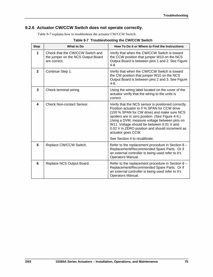
Troubleshooting
2/03 10260A Series Actuators – Installation, Operations, and Maintenance 75
9.2.6 Actuator CW/CCW Switch does not operate correctly. Table 9-7 explains how to troubleshoot the actuator CW/CCW Switch.
Table 9-7 Troubleshooting the CW/CCW Switch Step What to Do How To Do it or Where to Find the Instructions
1 Check that the CW/CCW Switch and the jumper on the NCS Output Board are correct.
Verify that when the CW/CCW Switch is toward the CCW position that jumper W10 on the NCS Output Board is between pins 1 and 2. See Figure 4-8.
2 Continue Step 1. Verify that when the CW/CCW Switch is toward the CW position that jumper W10 on the NCS Output Board is between pins 2 and 3. See Figure 4-8.
3 Check terminal wiring. Using the wiring label located on the cover of the actuator verify that the wiring to the units is correct.
4 Check Non-contact Sensor. Verify that the NCS sensor is positioned correctly. Position actuator to 0 % SPAN for CCW drive (100 % SPAN for CW drive) and make sure NCS spoilers are in zero position. (See Figure 4-4.) Using a DVM, measure voltage between pins on W11. Voltage should be between 0.01 V and 0.02 V in ZERO position and should increment as actuator goes CCW.
See Section 4 to recalibrate.
5 Replace CW/CCW Switch. Refer to the replacement procedure in Section 8 – Replacement/Recommended Spare Parts. Or if an external controller is being used refer to it’s Operators Manual.
6 Replace NCS Output Board. Refer to the replacement procedure in Section 8 – Replacement/Recommended Spare Parts. Or if an external controller is being used refer to it’s Operators Manual.
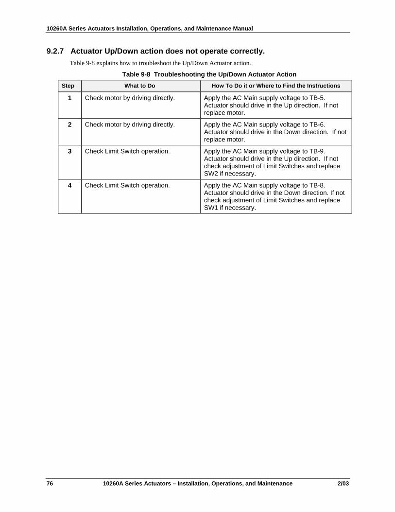
10260A Series Actuators Installation, Operations, and Maintenance Manual
76 10260A Series Actuators – Installation, Operations, and Maintenance 2/03
9.2.7 Actuator Up/Down action does not operate correctly. Table 9-8 explains how to troubleshoot the Up/Down Actuator action.
Table 9-8 Troubleshooting the Up/Down Actuator Action Step What to Do How To Do it or Where to Find the Instructions
1 Check motor by driving directly. Apply the AC Main supply voltage to TB-5. Actuator should drive in the Up direction. If not replace motor.
2 Check motor by driving directly. Apply the AC Main supply voltage to TB-6. Actuator should drive in the Down direction. If not replace motor.
3 Check Limit Switch operation. Apply the AC Main supply voltage to TB-9. Actuator should drive in the Up direction. If not check adjustment of Limit Switches and replace SW2 if necessary.
4 Check Limit Switch operation. Apply the AC Main supply voltage to TB-8. Actuator should drive in the Down direction. If not check adjustment of Limit Switches and replace SW1 if necessary.

Sales and Service
2/03 10260A Series Actuators – Installation, Operations, and Maintenance 77
10. Sales and Service For application assistance, current specifications, pricing, or name of the nearest Authorized Distributor,contact one of the offices below.
ARGENTINA Honeywell S.A.I.C. Belgrano 1156 Buenos Aires Argentina Tel. : 54 1 383 9290 ASIA PACIFIC Honeywell Asia Pacific Inc. Room 3213-3225 Sun Kung Kai Centre N° 30 Harbour Road Wanchai Hong Kong Tel. : 852 829 82 98 AUSTRALIA Honeywell Limited 5 Thomas Holt Drive North Ryde Sydney Nsw Australia 2113 Tel. : 61 2 353 7000 AUSTRIA Honeywell Austria G.M.B.H. Handelskai 388 A1020 Vienna Austria Tel. : 43 1 727 800 BELGIUM Honeywell S.A. 3 Avenue De Bourget B-1140 Brussels Belgium Tel. : 32 2 728 27 11 BRAZIL HONEYWELL DO Brazil And Cia Rua Jose Alves Da Chunha Lima 172 Butanta 05360.050 Sao Paulo Sp Brazil Tel. : 55 11 819 3755 BULGARIA HONEYWELL EOOD 14, Iskarsko Chausse POB 79 BG- 1592 Sofia BULGARIA Tel : 359-791512/ 794027/ 792198 CANADA Honeywell Limited The Honeywell Centre 300 Yorkland Blvd. Toronto, Ontario M2j 1s1 Canada Tel.: 800 461 0013 Fax:: 416 502 5001
CZECH REPUBLIC HONEYWELL, Spol.S.R.O. Budejovicka 1 140 21 Prague 4 Czech Republic Tel. : 42 2 6112 3434 DENMARK HONEYWELL A/S Automatikvej 1 DK 2860 Soeborg DENMARK Tel. : 45 39 55 56 58 FINLAND HONEYWELL OY Ruukintie 8 FIN-02320 ESPOO 32 FINLAND Tel. : 358 0 3480101 FRANCE HONEYWELL S.A. Bâtiment « le Mercury » Parc Technologique de St Aubin Route de l’Orme (CD 128) 91190 SAINT-AUBIN FRANCE Tel. from France: 01 60 19 80 00 From other countries: 33 1 60 19 80 00 GERMANY HONEYWELL AG Kaiserleistrasse 39 D-63067 OFFENBACH GERMANY Tel. : 49 69 80 64444 HUNGARY HONEYWELL Kft Gogol u 13 H-1133 BUDAPEST HUNGARY Tel. : 36 1 451 43 00 ICELAND HONEYWELL Hataekni .hf Armuli 26 PO Box 8336 128 reykjavik Iceland Tel : 354 588 5000 ITALY HONEYWELL S.p.A. Via P. Gobetti, 2/b 20063 Cernusco Sul Naviglio ITALY Tel. : 39 02 92146 1
MEXICO HONEYWELL S.A. DE CV AV. CONSTITUYENTES 900 COL. LOMAS ALTAS 11950 MEXICO CITY MEXICO Tel : 52 5 259 1966 THE NETHERLANDS HONEYWELL BV Laaderhoogtweg 18 1101 EA AMSTERDAM ZO THE NETHERLANDS Tel : 31 20 56 56 911 NORWAY HONEYWELL A/S Askerveien 61 PO Box 263 N-1371 ASKER NORWAY Tel. : 47 66 76 20 00 POLAND HONEYWELL Sp.z.o.o UI Domainewksa 41 02-672 WARSAW POLAND Tel. : 48 22 606 09 00 PORTUGAL HONEYWELL PORTUGAL LDA Edificio Suecia II Av. do Forte nr 3 - Piso 3 2795 CARNAXIDE PORTUGAL Tel. : 351 1 424 50 00 REPUBLIC OF IRELAND HONEYWELL Unit 1 Robinhood Business Park Robinhood Road DUBLIN 22 Republic of Ireland Tel. : 353 1 4565944 REPUBLIC OF SINGAPORE HONEYWELL PTE LTD BLOCK 750E CHAI CHEE ROAD 06-01 CHAI CHEE IND.PARK 1646 SINGAPORE REP. OF SINGAPORE Tel. : 65 2490 100
REPUBLIC OF SOUTH AFRICA HONEYWELL Southern Africa PO BOX 138 Milnerton 7435 REPUBLIC OF SOUTH AFRICA Tel. : 27 11 805 12 01 ROMANIA HONEYWELL Office Bucharest 147 Aurel Vlaicu Str., Sc.Z., Apt 61/62 R-72921 Bucharest ROMANIA Tel : 40-1 211 00 76/ 211 79 RUSSIA HONEYWELL INC 4 th Floor Administrative Builiding of AO "Luzhniki" Management 24 Luzhniki 119048 Moscow RUSSIA Tel : 7 095 796 98 00/01 SLOVAKIA HONEYWELL Ltd Mlynske nivy 73 PO Box 75 820 07 BRATISLAVA 27 SLOVAKIA Tel. : 421 7 52 47 400/425 SPAIN HONEYWELL S.A Factory Josefa Valcarcel, 24 28027 MADRID SPAIN Tel. : 34 91 31 3 61 00 SWEDEN HONEYWELL A.B. S-127 86 Skarholmen STOCKHOLM SWEDEN Tel. : 46 8 775 55 00 SWITZERLAND HONEYWELL A.G. Hertistrasse 2 8304 WALLISELLEN SWITZERLAND Tel. : 41 1 831 02 71 TURKEY HONEYWELL A.S. Caryiryolu Sok No. 7 Ucgen Plaza, Kat 5-6-7 Icerenkoy 81120 Instanbul Turkey Tel (90-216) 575 66 00 UNITED KINGDOM
HONEYWELL Newhouse Industrial Estate Motherwell. ML1. 5SB Scotland. UK. Tel: +44 (0)1698 481481 Fax: +44 (0) 1698 481276 U.S.A. HONEYWELL INC. INDUSTRIAL PROCESS CONTROLS 1100 VIRGINIA DRIVE PA 19034-3260 FT. WASHINGTON U.S.A. Tel. : 1-800-343-0228 VENEZUELA HONEYWELL CA APARTADO 61314 1060 CARACAS VENEZUELA Tel. : 58 2 239 0211

10260A Series Actuators Installation, Operations, and Maintenance Manual
78 10260A Series Actuators – Installation, Operations, and Maintenance 2/03


Industrial Measurement and Control Honeywell 1100 Virginia Drive Fort Washington, PA 19034
62-86-25-06 Rev. 6 0203 Printed in USA www.honeywell.com/imc