101st airborne divisionxa.yimg.com/kq/groups/21676676/717497623/name/air+assault+handb… · 101st...
TRANSCRIPT
101st Airborne Division (Air Assault)
1 2 The Sabalauski
3 Air Assault School Handbook
February 2007

WALTER JAMES SABALAUSKI (1910 - 1993)
Walter James Sabalauski was born in Lithuania in 1910. His family moved to the United States while he was a small child. From 1929 to 1937, he boxed professionally while living in the Chicago area. An auto accident ended his career with an outstanding record of only two defeats in 33 bouts. Command Sergeant Major Sabalauski entered the Army in June 1941. During World War II, he served in the Pacific Theater, fighting on the beachheads of the Solomon Islands, Guadalcanal, and the Philippines. He later served in the Korean War with the 187th Regiment, Combat Team (Airborne) and 25th Infantry Regiment. In 1963, CSM Sabalauski went to Vietnam for the first time, where he served as an advisor to the 32d Vietnamese Ranger Battalion. After service in the Dominican Republic in 1965, he returned to Vietnam in 1966. It was during this tour that he fought his most memorable battle. Early in June of 1966, Charlie Company, 2d Battalion, 502d Infantry Regiment was conducting a mission to locate elements of the 24th North Vietnamese Regiment. Charlie Company made contact with what was estimated to be a battalion-sized enemy element. Under heavy enemy fire and unable to maneuver, the company commander, CPT William Carpenter called for air strikes on his position in an attempt to force the enemy to withdraw. The enemy ceased fire long enough to allow Charlie Company to consolidate, reorganize and establish a position from which to defend and begin evacuation of wounded personnel. 1SG Sabalauski, in utter disregard for his own safety, repeatedly placed himself at risk for the sake of his soldiers during the conduct of this mission. For his extraordinary heroism in destroying the enemy and in evacuating the mass causalities, he received both the Distinguished Service Cross and the Silver Star. After his second tour in Vietnam he returned to the United States to serve as Cadet Regimental Sergeant Major at West Point. In 1968, he again returned to Vietnam and the 2-502d Infantry Regiment. Command Sergeant Major Sabalauski continued to serve until 1971 when he retired at the age of 61. Command Sergeant Major Sabalauski’s awards include the Distinguished Service Cross, Silver Star, Legion of Merit, 8 Bronze Stars, 3 Air Medals, 6 Army Commendation Medals, 4 Purple Hearts, 3 Awards of the Combat Infantryman’s Badge, the Master Parachutist Badge along with campaign medals for service in World War II, Korea, Dominican Republic, and Vietnam. Command Sergeant Major Sabalauski died in 1993 and was buried with full military honors in Arlington National Cemetery. To the soldiers who served with him, he is remembered as a fearless leader in combat and as having a heart as big as any country in which he served.
THE SCREAMING EAGLE SONG
We have a rendezvous with destiny.
Our strength and courage strike the spark
That will always make men free.
Assault right down through the skies of blue;
Keep your eyes on the job to be done.
We’re the soldiers of the hundred and first;
We’ll fight till the battle’s won!
AIR ASSAULT!!!
4 TABLE OF CONTENTS
CHAPTER ONE AIR ASSAULT OPERATIONS
PART I
ROTARY WING AIRCRAFT OF THE UNITED STATES ARMY 1-2
PART II
AIR CRAFT SAFETY 1-16
PART III
AEROMEDICAL EVACUATION PROCEDURES 1-18
PART IV
PATHFINDER OPERATIONS 1-22
PART V
HAND AND ARM SIGNALS 1-36
PART VI
COMBAT ASSAULT 1-46 AIR MISSION BRIEF 1-54 COLD LOAD TRAINING 1-56
PART VII CLOSE COMBAT ATTACK 1-60
CHAPTER TWO HELICOPTER EXTERNAL LOAD OPERATIONS
PART I
5 GENERAL 2-1
PART II
CERTIFIED SLINGLOADS 2-17 5,000 AND 10,000 POUND CAPACITY CARGO NET 2-20 A-22 CARGO BAG 2-25 M998/M1038 TRUCK, CARGO, 1 ¼ TON (HMMWV) 2-30 ONE TO FOUR 500 GALLON FUEL DRUMS 2-37 SIDE BY SIDE RIGGING PROCEDURES FOR M998/1038 2-45 CARGO/TROOP (HMMWV), (SHOTGUN) M996/M1036/M1045/ M1046 TOW MISSILE CARRIER M119A2 105MM HOWITZER 2-52
PART III
M149-SERIES WATER TRAILER 2-60 M1097/M1097A1/M1097A2 2-65
PART IV UNIQUE (NON-STANDARD) SLING LOADS 2-72
CHAPTER THREE RAPPELLING
PART I
BASIC COMBAT RAPPELLING 3-1
6 PART II
FRIES TRAINING (FAST ROPE INFILTRATION, EXTRACTION SYS) 3-13
APPENDICES
APPENDIX A
NINE LINE MEDEVAC REQUEST A-1
APPENDIX B AIR MISSION BRIEF B-1
APPENDIX C EXAMPLE AIR MOVEMENT TABLE C-1
APPENDIX D EXAMPLE AIR LOAD TABLE D-1
APPENDIX E
CLOSE COMBAT ATTACK UNIT & ENEMY LOCATION MARKINGS E-1
APPENDIX F
SLINGLOAD INSPECTION SEQUENCE F-1
APPENDIX G SLING CONVERSION TABLE G-1
APPENDIX H DA FORM 5752-R ROPE USAGE LOG H-1
APPENDIX I SLINGLOAD INSPECTION RECORD INSTRUCTIONS I-1 DA FORM 7382-R SLINGLOAD INSPECTION RECORD I-2
APPENXDIX J FUEL BLIVET CONFIGURATION J-1
APPENDIX K RIGGING AND SLINGLOADING CHART K-1
1 -1
CHAPTER ONE
AIR ASSAULT OPERATIONS REFERENCES: A. FM 90-4, Air Assault Operations, March 1987 B. FM 3-21.38, Pathfinder Operations, October 2002 C. FM 8-10-6, Medical Evacuation in a Theater of Operation, 14 April 2000 D. TM 1-1520-248-10, Army Model OH-58D Helicopter, 15 November 2001 (w/ changes 1 through 7, dated 15 October 2003). E. TM 1-1520-237-10, Army Model UH-60A/L Helicopter, 1 May 2003 F. TM 1-1520-238-10, Army Model AH-64A Helicopter, 13 August 1994 (w/ changes 1 through 11, dated 14 February 2003). G. TM 1-1520-251-10, Army Model AH-64D Helicopter, March 2002(w/ changes 1 through 3, dated 30 April 2004). H. TM 1-1520-240-10, Army Model CH-47D Helicopter, 31 January 2003 (w/ changes 1 through 4, dated 21 January 2005). I. TM 1-1520-252-10, Army Model MH-47E Helicopter, 28 June 1995 (w/ changes 1 through 13, dated 30 June 2003). J. FM 3-04.111, Aviation Brigades, August 2003. K. FM 1-112, Attack Helicopter Operations, 2 April 1997. L. FM 1-113, Utility and Cargo Helicopter Operations, 12 September 1997. M. FM 7-8, Infantry Rifle Platoon and Squad w/ change 1, 1 March 2001.
1 -2
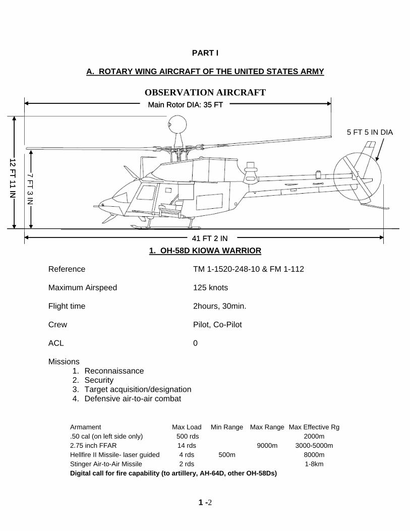
PART I
A. ROTARY WING AIRCRAFT OF THE UNITED STATES ARMY
OBSERVATION AIRCRAFT Main Rotor DIA: 35 FT
41 FT 2 IN
5 FT 5 IN DIA
12 FT 11 IN
7 FT 3 IN
Main Rotor DIA: 35 FT
41 FT 2 IN
5 FT 5 IN DIA
12 FT 11 IN
7 FT 3 IN
1. OH-58D KIOWA WARRIOR
Reference TM 1-1520-248-10 & FM 1-112 Maximum Airspeed 125 knots Flight time 2hours, 30min. Crew Pilot, Co-Pilot ACL 0 Missions
1. Reconnaissance 2. Security 3. Target acquisition/designation 4. Defensive air-to-air combat
Armament Max Load Min Range Max Range Max Effective Rg.50 cal (on left side only) 500 rds 2000m 2.75 inch FFAR 14 rds 9000m 3000-5000m Hellfire II Missile- laser guided 4 rds 500m 8000m Stinger Air-to-Air Missile 2 rds 1-8km Digital call for fire capability (to artillery, AH-64D, other OH-58Ds)
1 -3
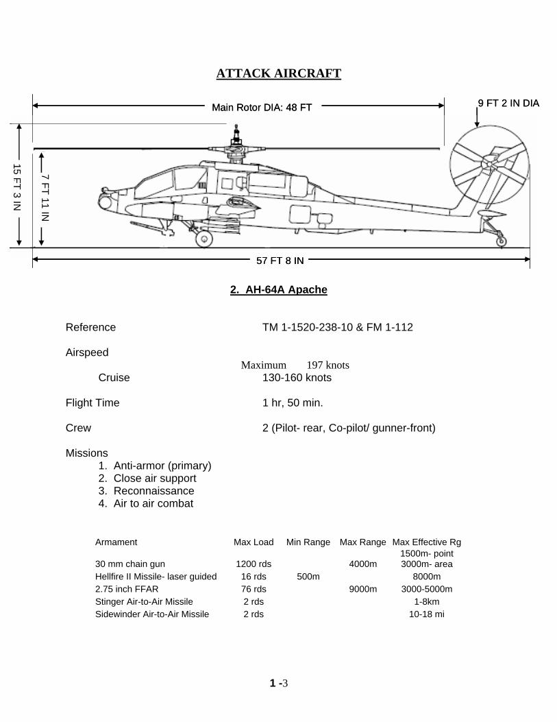
ATTACK AIRCRAFT
Main Rotor DIA: 48 FT
57 FT 8 IN
9 FT 2 IN DIA
15 FT 3 IN
7 FT 11 IN
Main Rotor DIA: 48 FT
57 FT 8 IN
9 FT 2 IN DIA
15 FT 3 IN
7 FT 11 IN
2. AH-64A Apache
Reference TM 1-1520-238-10 & FM 1-112 Airspeed
Maximum 197 knots Cruise 130-160 knots Flight Time 1 hr, 50 min. Crew 2 (Pilot- rear, Co-pilot/ gunner-front) Missions 1. Anti-armor (primary) 2. Close air support 3. Reconnaissance 4. Air to air combat
Armament Max Load Min Range Max Range Max Effective Rg
30 mm chain gun 1200 rds 4000m 1500m- point 3000m- area
Hellfire II Missile- laser guided 16 rds 500m 8000m 2.75 inch FFAR 76 rds 9000m 3000-5000m Stinger Air-to-Air Missile 2 rds 1-8km Sidewinder Air-to-Air Missile 2 rds 10-18 mi
1 -4
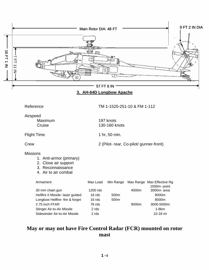
Main Rotor DIA: 48 FT
57 FT 8 IN
9 FT 2 IN DIA
16 FT 1 IN
7 FT 11 IN
Main Rotor DIA: 48 FT
57 FT 8 IN
9 FT 2 IN DIA
16 FT 1 IN
7 FT 11 IN
3. AH-64D Longbow Apache
Reference TM 1-1520-251-10 & FM 1-112 Airspeed Maximum 197 knots Cruise 130-160 knots Flight Time 1 hr, 50 min. Crew 2 (Pilot- rear, Co-pilot/ gunner-front) Missions 1. Anti-armor (primary) 2. Close air support 3. Reconnaissance 4. Air to air combat
Armament Max Load Min Range Max Range Max Effective Rg
30 mm chain gun 1200 rds 4000m 1500m- point 3000m- area
Hellfire II Missile- laser guided 16 rds 500m 8000m Longbow Hellfire- fire & forget 16 rds 500m 8000m 2.75 inch FFAR 76 rds 9000m 3000-5000m Stinger Air-to-Air Missile 2 rds 1-8km Sidewinder Air-to-Air Missile 2 rds 10-18 mi
May or may not have Fire Control Radar (FCR) mounted on rotor
mast
1 -5
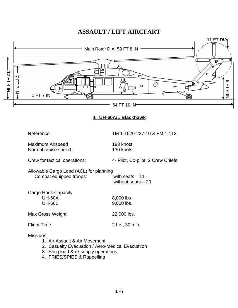
ASSAULT / LIFT AIRCFART
Main Rotor DIA: 53 FT 8 IN
64 FT 10 IN
11 FT DIA
12 FT 4 IN
7 FT 7 IN
6 FT 6 IN1 FT 7 IN
Main Rotor DIA: 53 FT 8 IN
64 FT 10 IN
11 FT DIA
12 FT 4 IN
7 FT 7 IN
6 FT 6 IN1 FT 7 IN
4. UH-60A/L Blackhawk
Reference TM 1-1520-237-10 & FM 1-113 Maximum Airspeed 193 knots Normal cruise speed 130 knots Crew for tactical operations: 4- Pilot, Co-pilot, 2 Crew Chiefs Allowable Cargo Load (ACL) for planning Combat equipped troops: with seats – 11 without seats – 20 Cargo Hook Capacity UH-60A 8,000 lbs UH-60L 9,000 lbs. Max Gross Weight 22,000 lbs. Flight Time 2 hrs, 30 min. Missions 1. Air Assault & Air Movement 2. Casualty Evacuation / Aero-Medical Evacuation 3. Sling load & re-supply operations 4. FRIES/SPIES & Rappelling
1 -6
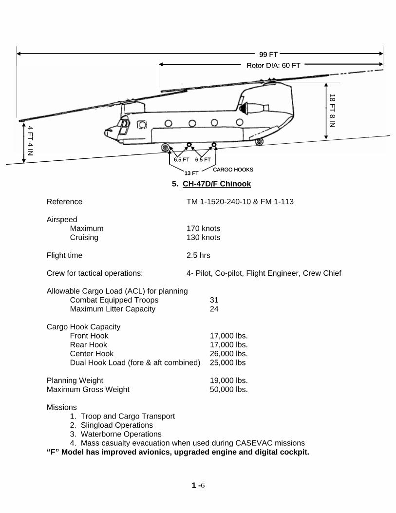
Rotor DIA: 60 FT99 FT
13 FT
18 FT 8 IN4 FT 4 IN
6.5 FT6.5 FT
CARGO HOOKS
Rotor DIA: 60 FT99 FT
13 FT
18 FT 8 IN4 FT 4 IN
6.5 FT6.5 FT
CARGO HOOKS
5. CH-47D/F Chinook Reference TM 1-1520-240-10 & FM 1-113 Airspeed Maximum 170 knots Cruising 130 knots Flight time 2.5 hrs Crew for tactical operations: 4- Pilot, Co-pilot, Flight Engineer, Crew Chief Allowable Cargo Load (ACL) for planning Combat Equipped Troops 31 Maximum Litter Capacity 24 Cargo Hook Capacity Front Hook 17,000 lbs. Rear Hook 17,000 lbs. Center Hook 26,000 lbs. Dual Hook Load (fore & aft combined) 25,000 lbs Planning Weight 19,000 lbs. Maximum Gross Weight 50,000 lbs. Missions 1. Troop and Cargo Transport 2. Slingload Operations 3. Waterborne Operations 4. Mass casualty evacuation when used during CASEVAC missions “F” Model has improved avionics, upgraded engine and digital cockpit.
1 -7
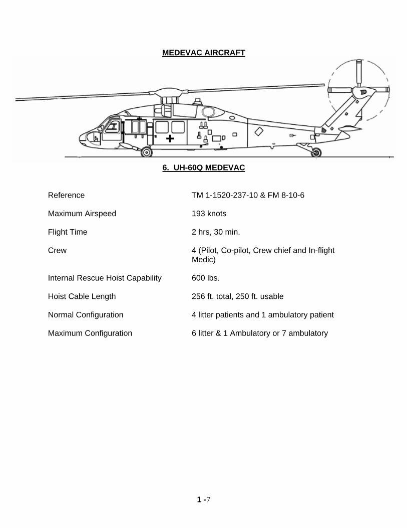
MEDEVAC AIRCRAFT
6. UH-60Q MEDEVAC
Reference TM 1-1520-237-10 & FM 8-10-6 Maximum Airspeed 193 knots Flight Time 2 hrs, 30 min. Crew 4 (Pilot, Co-pilot, Crew chief and In-flight
Medic) Internal Rescue Hoist Capability 600 lbs. Hoist Cable Length 256 ft. total, 250 ft. usable Normal Configuration 4 litter patients and 1 ambulatory patient Maximum Configuration 6 litter & 1 Ambulatory or 7 ambulatory
1 -8
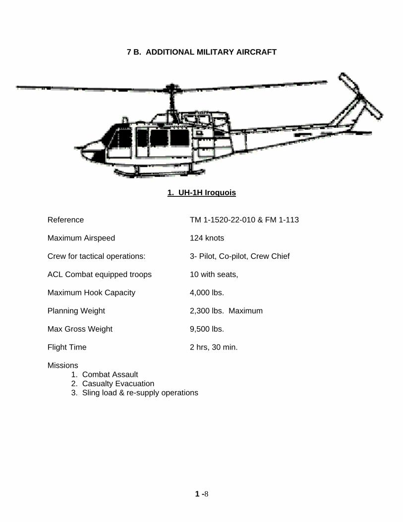
7 B. ADDITIONAL MILITARY AIRCRAFT
1. UH-1H Iroquois
Reference TM 1-1520-22-010 & FM 1-113 Maximum Airspeed 124 knots Crew for tactical operations: 3- Pilot, Co-pilot, Crew Chief ACL Combat equipped troops 10 with seats, Maximum Hook Capacity 4,000 lbs. Planning Weight 2,300 lbs. Maximum Max Gross Weight 9,500 lbs. Flight Time 2 hrs, 30 min. Missions 1. Combat Assault 2. Casualty Evacuation 3. Sling load & re-supply operations
1 -9
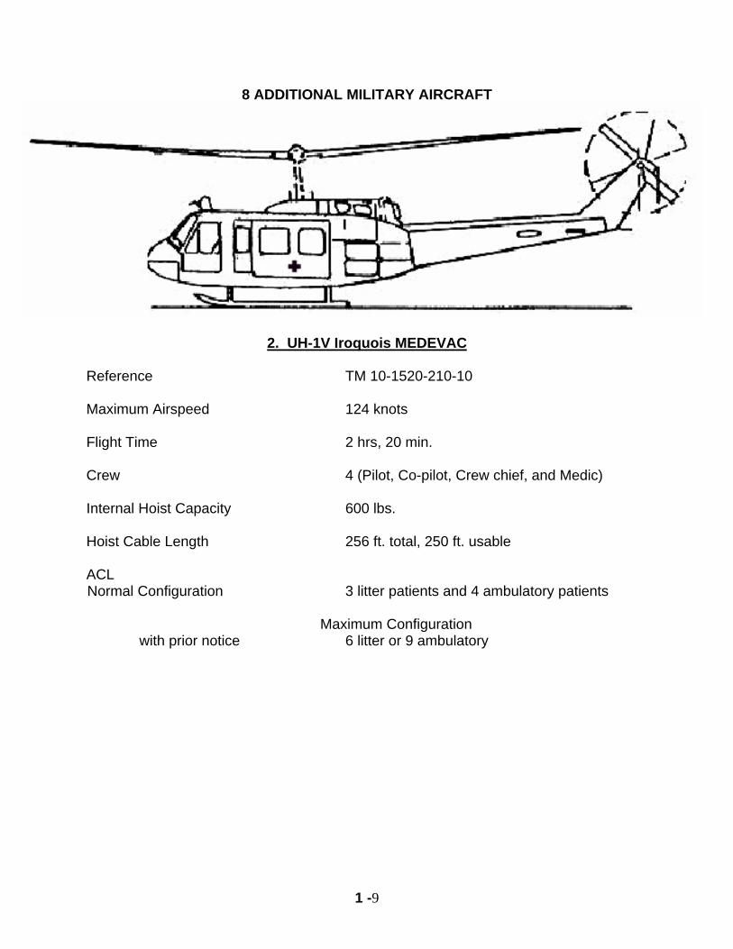
8 ADDITIONAL MILITARY AIRCRAFT
2. UH-1V Iroquois MEDEVAC Reference TM 10-1520-210-10 Maximum Airspeed 124 knots Flight Time 2 hrs, 20 min. Crew 4 (Pilot, Co-pilot, Crew chief, and Medic) Internal Hoist Capacity 600 lbs. Hoist Cable Length 256 ft. total, 250 ft. usable ACL Normal Configuration 3 litter patients and 4 ambulatory patients Maximum Configuration with prior notice 6 litter or 9 ambulatory
1 -10
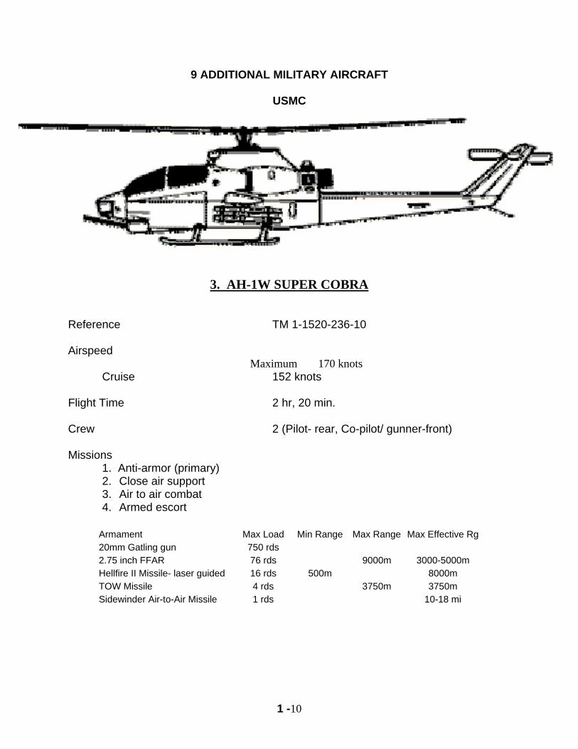
9 ADDITIONAL MILITARY AIRCRAFT
USMC
3. AH-1W SUPER COBRA
Reference TM 1-1520-236-10 Airspeed
Maximum 170 knots Cruise 152 knots Flight Time 2 hr, 20 min. Crew 2 (Pilot- rear, Co-pilot/ gunner-front) Missions 1. Anti-armor (primary)
2. Close air support 3. Air to air combat 4. Armed escort
Armament Max Load Min Range Max Range Max Effective Rg20mm Gatling gun 750 rds 2.75 inch FFAR 76 rds 9000m 3000-5000m Hellfire II Missile- laser guided 16 rds 500m 8000m TOW Missile 4 rds 3750m 3750m Sidewinder Air-to-Air Missile 1 rds 10-18 mi
1 -11
10 ADDITIONAL MILITARY AIRCRAFT
SPECIAL OPERATIONS
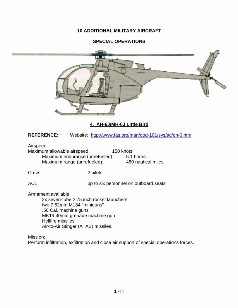
4. AH-6J/MH-6J Little Bird
REFERENCE: Website: http://www.fas.org/man/dod-101/sys/ac/oh-6.htm Airspeed Maximum allowable airspeed: 150 knots
Maximum endurance (unrefueled): 5.1 hours Maximum range (unrefueled): 480 nautical miles
Crew 2 pilots ACL up to six personnel on outboard seats Armament available:
2x seven-tube 2.75 inch rocket launchers two 7.62mm M134 "miniguns" .50 Cal. machine guns MK19 40mm grenade machine gun Hellfire missiles Air-to-Air Stinger (ATAS) missiles.
Mission: Perform infiltration, exfiltration and close air support of special operations forces.
1 -12
11 ADDITIONAL MILITARY AIRCRAFT SPECIAL OPERATIONS
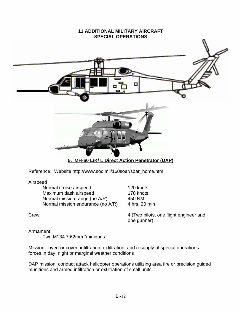
5. MH-60 L/K/ L Direct Action Penetrator (DAP)
Reference: Website http://www.soc.mil/160soar/soar_home.htm Airspeed
Normal cruise airspeed 120 knots Maximum dash airspeed 178 knots Normal mission range (no A/R) 450 NM Normal mission endurance (no A/R) 4 hrs, 20 min
Crew 4 (Two pilots, one flight engineer and
one gunner) Armament: Two M134 7.62mm "miniguns Mission: overt or covert infiltration, exfiltration, and resupply of special operations forces in day, night or marginal weather conditions DAP mission: conduct attack helicopter operations utilizing area fire or precision guided munitions and armed infiltration or exfiltration of small units.
1 -13
12 ADDITIONAL MILITARY AIRCRAFT SPECIAL OPERATIONS
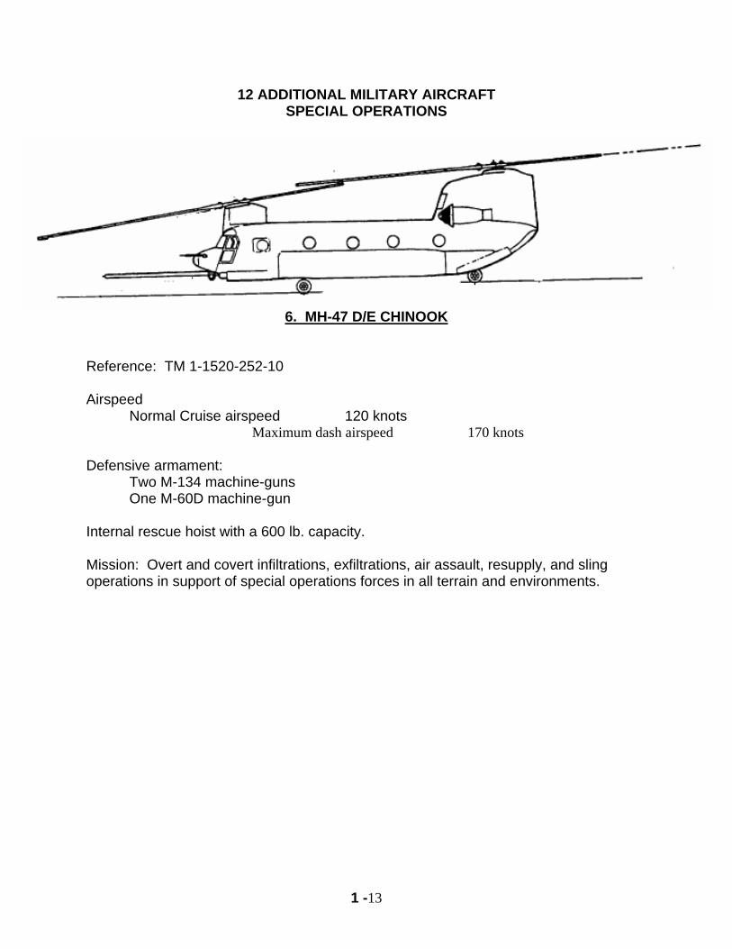
6. MH-47 D/E CHINOOK
Reference: TM 1-1520-252-10 Airspeed Normal Cruise airspeed 120 knots
Maximum dash airspeed 170 knots Defensive armament:
Two M-134 machine-guns One M-60D machine-gun
Internal rescue hoist with a 600 lb. capacity. Mission: Overt and covert infiltrations, exfiltrations, air assault, resupply, and sling operations in support of special operations forces in all terrain and environments.
1 -14
13 ADDITIONAL MILITARY AIRCRAFT
USAF
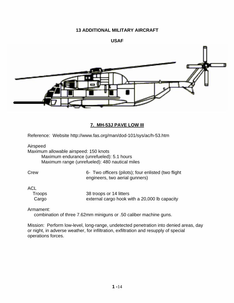
7. MH-53J PAVE LOW III
Reference: Website http://www.fas.org/man/dod-101/sys/ac/h-53.htm Airspeed Maximum allowable airspeed: 150 knots
Maximum endurance (unrefueled): 5.1 hours Maximum range (unrefueled): 480 nautical miles
Crew 6- Two officers (pilots); four enlisted (two flight
engineers, two aerial gunners) ACL Troops 38 troops or 14 litters Cargo external cargo hook with a 20,000 lb capacity Armament: combination of three 7.62mm miniguns or .50 caliber machine guns. Mission: Perform low-level, long-range, undetected penetration into denied areas, day or night, in adverse weather, for infiltration, exfiltration and resupply of special operations forces.
1 -15
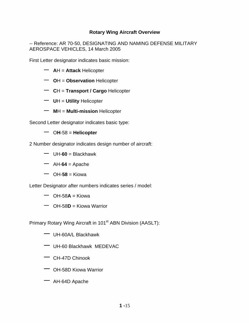
Rotary Wing Aircraft Overview
-- Reference: AR 70-50, DESIGNATING AND NAMING DEFENSE MILITARY AEROSPACE VEHICLES, 14 March 2005
First Letter designator indicates basic mission:
– AH = Attack Helicopter
– OH = Observation Helicopter
– CH = Transport / Cargo Helicopter
– UH = Utility Helicopter
– MH = Multi-mission Helicopter Second Letter designator indicates basic type:
– OH-58 = Helicopter 2 Number designator indicates design number of aircraft:
– UH-60 = Blackhawk
– AH-64 = Apache
– OH-58 = Kiowa Letter Designator after numbers indicates series / model:
– OH-58A = Kiowa
– OH-58D = Kiowa Warrior
Primary Rotary Wing Aircraft in 101st ABN Division (AASLT):
– UH-60A/L Blackhawk
– UH-60 Blackhawk MEDEVAC
– CH-47D Chinook
– OH-58D Kiowa Warrior
– AH-64D Apache
1 -16
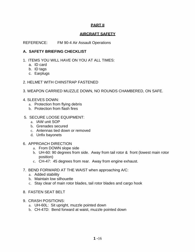
PART II
AIRCRAFT SAFETY REFERENCE: FM 90-4 Air Assault Operations A. SAFETY BRIEFING CHECKLIST 1. ITEMS YOU WILL HAVE ON YOU AT ALL TIMES:
a. ID card b. ID tags c. Earplugs
2. HELMET WITH CHINSTRAP FASTENED 3. WEAPON CARRIED MUZZLE DOWN, NO ROUNDS CHAMBERED, ON SAFE. 4. SLEEVES DOWN:
a. Protection from flying debris b. Protection from flash fires
5. SECURE LOOSE EQUIPMENT: a. IAW unit SOP b. Grenades secured c. Antennas tied down or removed d. Unfix bayonets
6. APPROACH DIRECTION
a. From DOWN slope side b. UH-60: 90 degrees from side. Away from tail rotor & front (lowest main rotor
position) c. CH-47: 45 degrees from rear. Away from engine exhaust.
7. BEND FORWARD AT THE WAIST when approaching A/C:
a. Added stability b. Maintain low silhouette c. Stay clear of main rotor blades, tail rotor blades and cargo hook
8. FASTEN SEAT BELT 9. CRASH POSITIONS:
a. UH-60L: Sit upright, muzzle pointed down b. CH-47D: Bend forward at waist, muzzle pointed down
1 -17
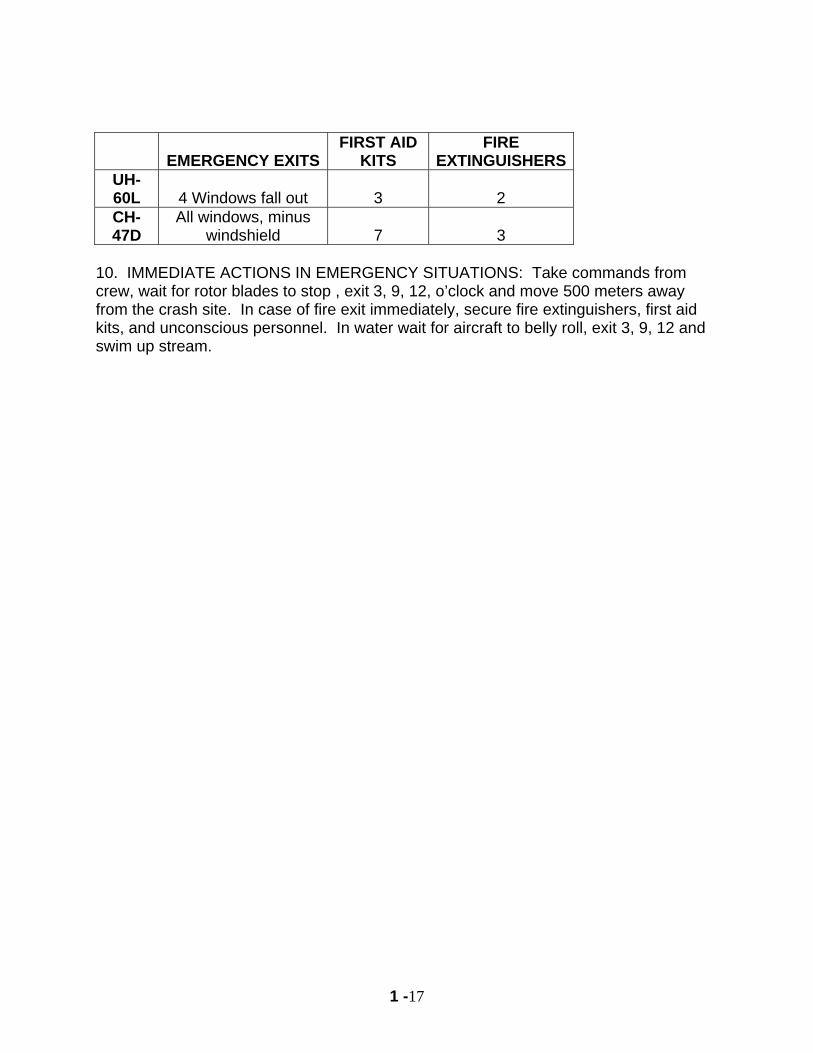
EMERGENCY EXITS FIRST AID
KITS FIRE
EXTINGUISHERSUH-60L 4 Windows fall out 3 2 CH-47D
All windows, minus windshield 7 3
10. IMMEDIATE ACTIONS IN EMERGENCY SITUATIONS: Take commands from crew, wait for rotor blades to stop , exit 3, 9, 12, o’clock and move 500 meters away from the crash site. In case of fire exit immediately, secure fire extinguishers, first aid kits, and unconscious personnel. In water wait for aircraft to belly roll, exit 3, 9, 12 and swim up stream.
1 -18
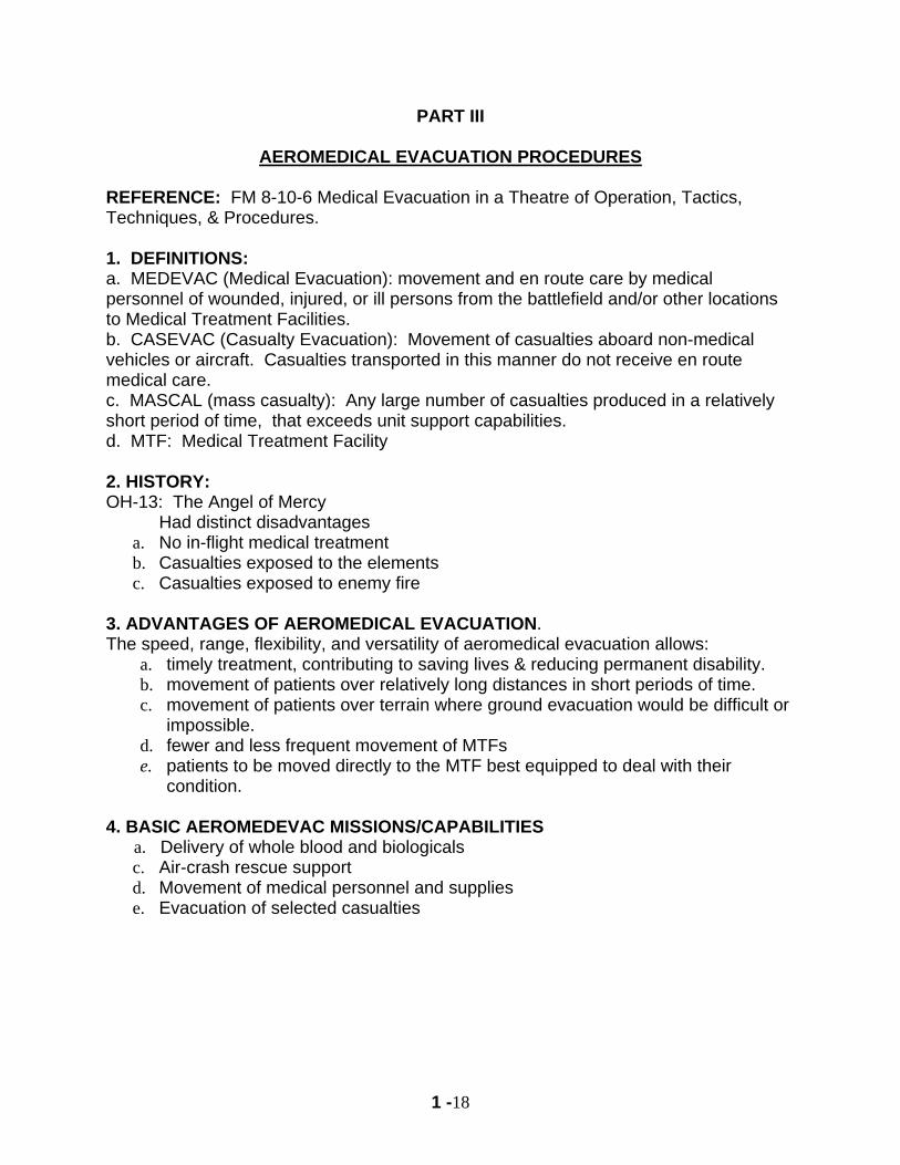
PART III
AEROMEDICAL EVACUATION PROCEDURES
REFERENCE: FM 8-10-6 Medical Evacuation in a Theatre of Operation, Tactics, Techniques, & Procedures. 1. DEFINITIONS: a. MEDEVAC (Medical Evacuation): movement and en route care by medical personnel of wounded, injured, or ill persons from the battlefield and/or other locations to Medical Treatment Facilities. b. CASEVAC (Casualty Evacuation): Movement of casualties aboard non-medical vehicles or aircraft. Casualties transported in this manner do not receive en route medical care. c. MASCAL (mass casualty): Any large number of casualties produced in a relatively short period of time, that exceeds unit support capabilities. d. MTF: Medical Treatment Facility 2. HISTORY: OH-13: The Angel of Mercy Had distinct disadvantages
a. No in-flight medical treatment b. Casualties exposed to the elements c. Casualties exposed to enemy fire
3. ADVANTAGES OF AEROMEDICAL EVACUATION. The speed, range, flexibility, and versatility of aeromedical evacuation allows:
a. timely treatment, contributing to saving lives & reducing permanent disability. b. movement of patients over relatively long distances in short periods of time. c. movement of patients over terrain where ground evacuation would be difficult or
impossible. d. fewer and less frequent movement of MTFs e. patients to be moved directly to the MTF best equipped to deal with their
condition.
4. BASIC AEROMEDEVAC MISSIONS/CAPABILITIES a. Delivery of whole blood and biologicals c. Air-crash rescue support d. Movement of medical personnel and supplies e. Evacuation of selected casualties
1 -19
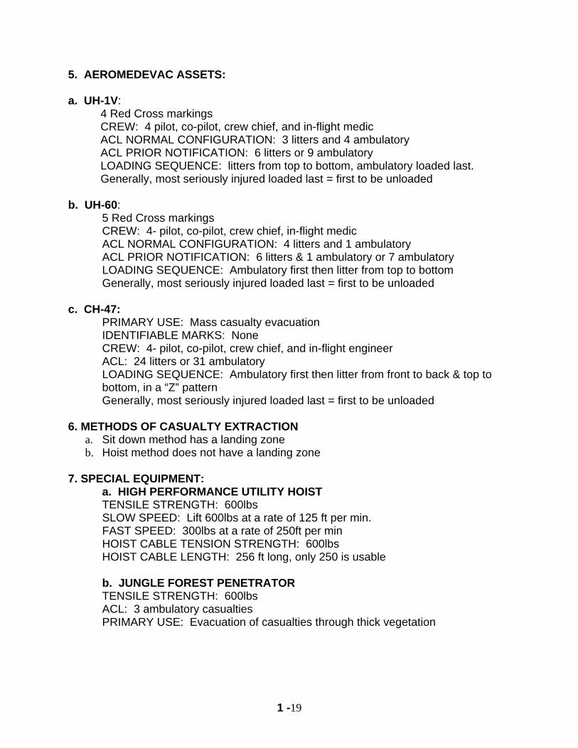
5. AEROMEDEVAC ASSETS:
a. UH-1V: 4 Red Cross markings CREW: 4 pilot, co-pilot, crew chief, and in-flight medic ACL NORMAL CONFIGURATION: 3 litters and 4 ambulatory ACL PRIOR NOTIFICATION: 6 litters or 9 ambulatory LOADING SEQUENCE: litters from top to bottom, ambulatory loaded last. Generally, most seriously injured loaded last = first to be unloaded
b. UH-60:
5 Red Cross markings CREW: 4- pilot, co-pilot, crew chief, in-flight medic ACL NORMAL CONFIGURATION: 4 litters and 1 ambulatory ACL PRIOR NOTIFICATION: 6 litters & 1 ambulatory or 7 ambulatory LOADING SEQUENCE: Ambulatory first then litter from top to bottom Generally, most seriously injured loaded last = first to be unloaded
c. CH-47: PRIMARY USE: Mass casualty evacuation IDENTIFIABLE MARKS: None CREW: 4- pilot, co-pilot, crew chief, and in-flight engineer ACL: 24 litters or 31 ambulatory LOADING SEQUENCE: Ambulatory first then litter from front to back & top to bottom, in a “Z” pattern Generally, most seriously injured loaded last = first to be unloaded
6. METHODS OF CASUALTY EXTRACTION a. Sit down method has a landing zone b. Hoist method does not have a landing zone
7. SPECIAL EQUIPMENT: a. HIGH PERFORMANCE UTILITY HOIST TENSILE STRENGTH: 600lbs SLOW SPEED: Lift 600lbs at a rate of 125 ft per min. FAST SPEED: 300lbs at a rate of 250ft per min HOIST CABLE TENSION STRENGTH: 600lbs HOIST CABLE LENGTH: 256 ft long, only 250 is usable b. JUNGLE FOREST PENETRATOR TENSILE STRENGTH: 600lbs ACL: 3 ambulatory casualties PRIMARY USE: Evacuation of casualties through thick vegetation
1 -20
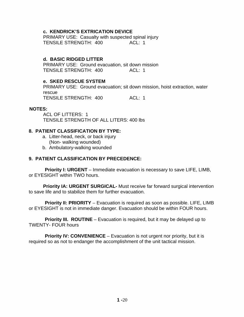
c. KENDRICK’S EXTRICATION DEVICE PRIMARY USE: Casualty with suspected spinal injury TENSILE STRENGTH: 400 ACL: 1 d. BASIC RIDGED LITTER PRIMARY USE: Ground evacuation, sit down mission TENSILE STRENGTH: 400 ACL: 1 e. SKED RESCUE SYSTEM PRIMARY USE: Ground evacuation; sit down mission, hoist extraction, water rescue TENSILE STRENGTH: 400 ACL: 1
NOTES: ACL OF LITTERS: 1 TENSILE STRENGTH OF ALL LITERS: 400 lbs 8. PATIENT CLASSIFICATION BY TYPE:
a. Litter-head, neck, or back injury (Non- walking wounded) b. Ambulatory-walking wounded
9. PATIENT CLASSIFICATION BY PRECEDENCE: Priority I: URGENT – Immediate evacuation is necessary to save LIFE, LIMB, or EYESIGHT within TWO hours. Priority IA: URGENT SURGICAL- Must receive far forward surgical intervention to save life and to stabilize them for further evacuation. Priority II: PRIORITY – Evacuation is required as soon as possible. LIFE, LIMB or EYESIGHT is not in immediate danger. Evacuation should be within FOUR hours. Priority III. ROUTINE – Evacuation is required, but it may be delayed up to TWENTY- FOUR hours Priority IV: CONVENIENCE – Evacuation is not urgent nor priority, but it is required so as not to endanger the accomplishment of the unit tactical mission.
1 -21
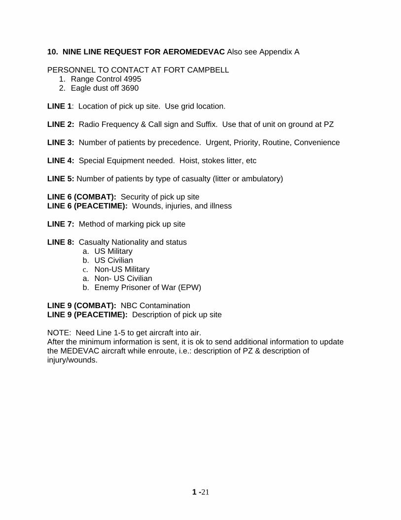
10. NINE LINE REQUEST FOR AEROMEDEVAC Also see Appendix A PERSONNEL TO CONTACT AT FORT CAMPBELL
1. Range Control 4995 2. Eagle dust off 3690
LINE 1: Location of pick up site. Use grid location. LINE 2: Radio Frequency & Call sign and Suffix. Use that of unit on ground at PZ LINE 3: Number of patients by precedence. Urgent, Priority, Routine, Convenience LINE 4: Special Equipment needed. Hoist, stokes litter, etc LINE 5: Number of patients by type of casualty (litter or ambulatory) LINE 6 (COMBAT): Security of pick up site LINE 6 (PEACETIME): Wounds, injuries, and illness LINE 7: Method of marking pick up site LINE 8: Casualty Nationality and status
a. US Military b. US Civilian c. Non-US Military a. Non- US Civilian b. Enemy Prisoner of War (EPW)
LINE 9 (COMBAT): NBC Contamination LINE 9 (PEACETIME): Description of pick up site NOTE: Need Line 1-5 to get aircraft into air. After the minimum information is sent, it is ok to send additional information to update the MEDEVAC aircraft while enroute, i.e.: description of PZ & description of injury/wounds.
1 -22
PART IV
PATHFINDER OPERATIONS
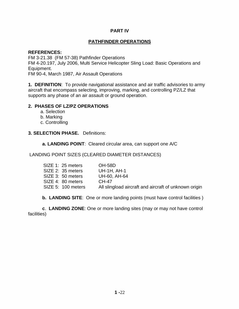
REFERENCES: FM 3-21.38 (FM 57-38) Pathfinder Operations FM 4-20.197, July 2006, Multi Service Helicopter Sling Load: Basic Operations and Equipment. FM 90-4, March 1987, Air Assault Operations 1. DEFINITION: To provide navigational assistance and air traffic advisories to army aircraft that encompass selecting, improving, marking, and controlling PZ/LZ that supports any phase of an air assault or ground operation. 2. PHASES OF LZ/PZ OPERATIONS
a. Selection b. Marking c. Controlling
3. SELECTION PHASE. Definitions:
a. LANDING POINT: Cleared circular area, can support one A/C LANDING POINT SIZES (CLEARED DIAMETER DISTANCES)
SIZE 1: 25 meters OH-58D SIZE 2: 35 meters UH-1H, AH-1 SIZE 3: 50 meters UH-60, AH-64 SIZE 4: 80 meters CH-47 SIZE 5: 100 meters All slingload aircraft and aircraft of unknown origin
b. LANDING SITE: One or more landing points (must have control facilities )
c. LANDING ZONE: One or more landing sites (may or may not have control
facilities)
1 -23
4. REQUIREMENTS OF LZ. Must consider the following: a. NUMBER OF A/C: PZ/LZ must support both number and type of A/C
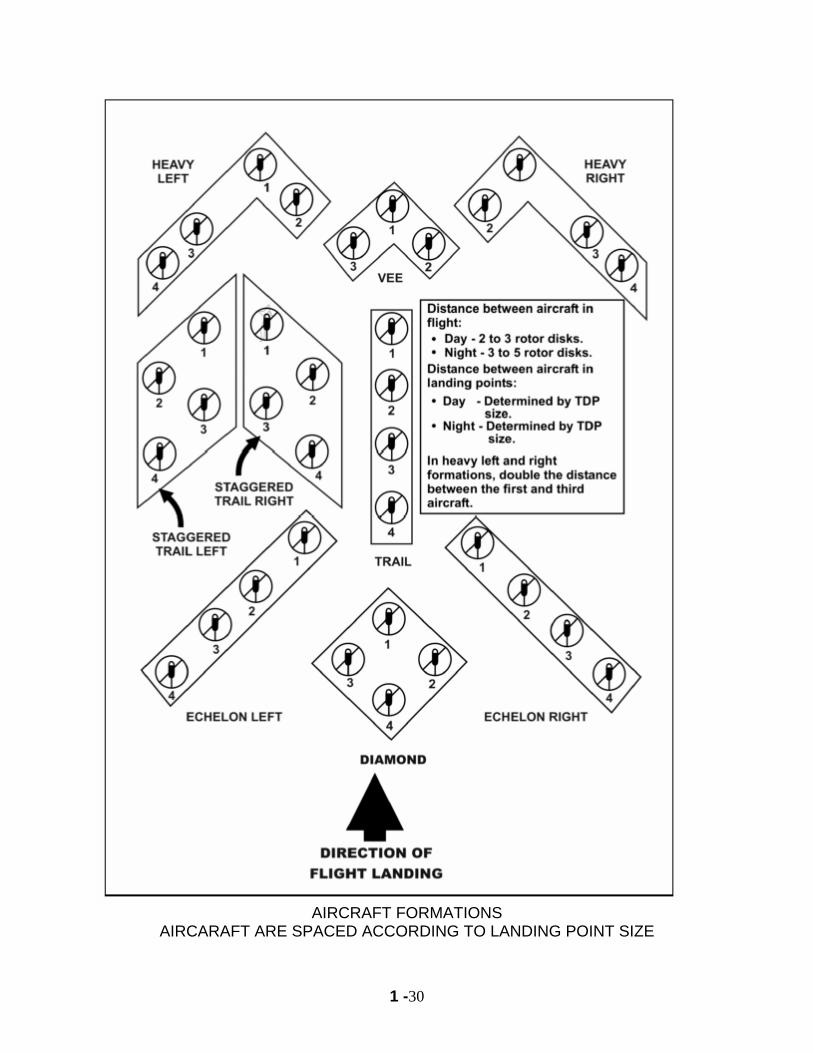
b. FLYING/ LANDING FORMATIONS: 9 standard A/C formations:
(1) Trail (2) Echelon Left/Right (3) Heavy Left/Right (4) Staggered trail left/right (5) Vee (6) Diamond
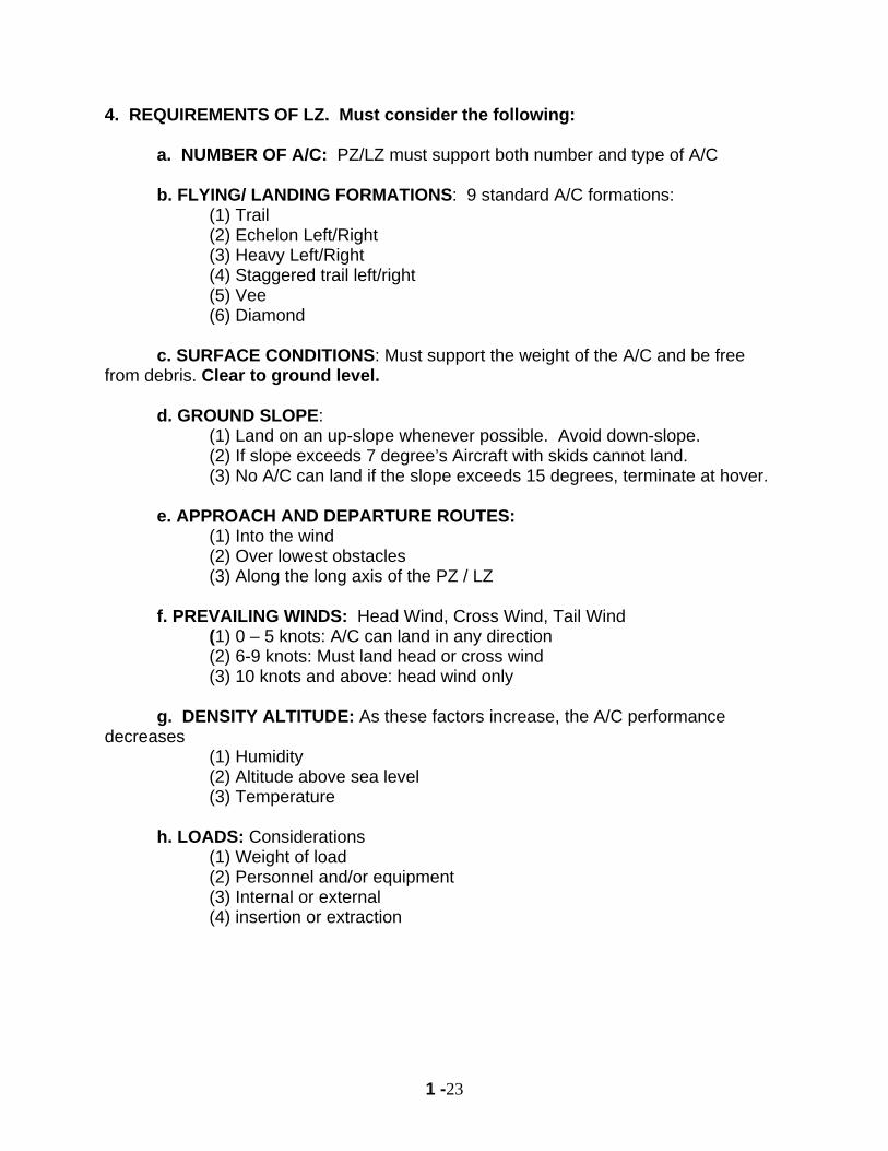
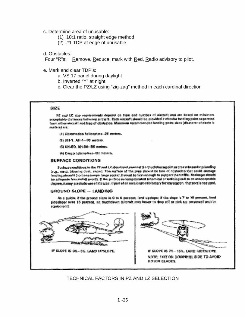
c. SURFACE CONDITIONS: Must support the weight of the A/C and be free from debris. Clear to ground level.
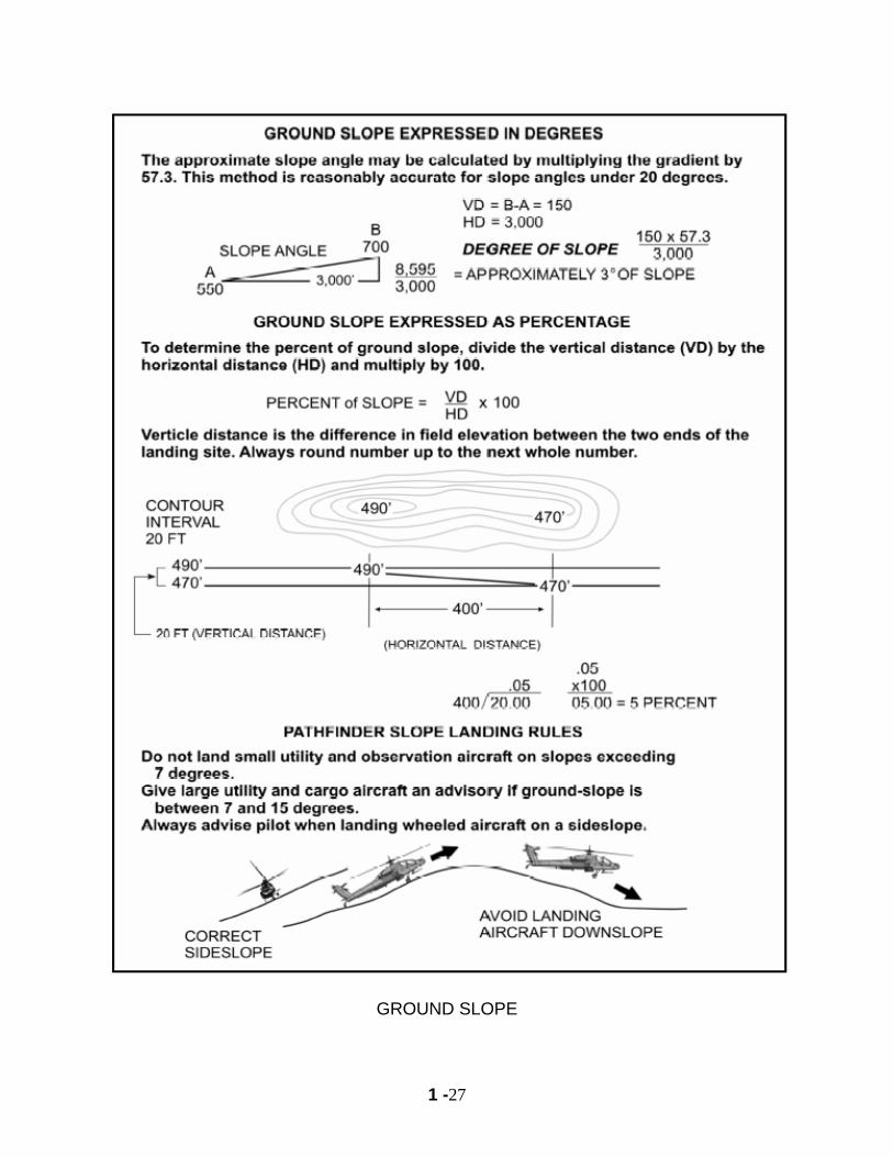
d. GROUND SLOPE: (1) Land on an up-slope whenever possible. Avoid down-slope. (2) If slope exceeds 7 degree’s Aircraft with skids cannot land. (3) No A/C can land if the slope exceeds 15 degrees, terminate at hover.
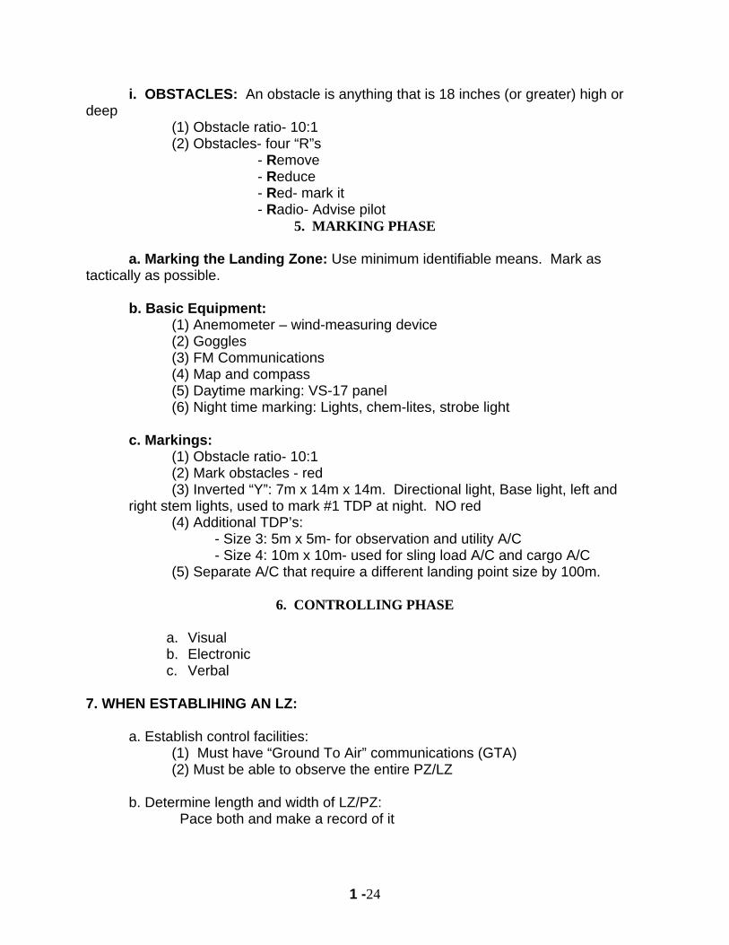
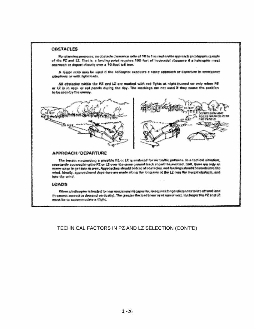
e. APPROACH AND DEPARTURE ROUTES: (1) Into the wind (2) Over lowest obstacles (3) Along the long axis of the PZ / LZ
f. PREVAILING WINDS: Head Wind, Cross Wind, Tail Wind (1) 0 – 5 knots: A/C can land in any direction (2) 6-9 knots: Must land head or cross wind (3) 10 knots and above: head wind only
g. DENSITY ALTITUDE: As these factors increase, the A/C performance decreases
(1) Humidity (2) Altitude above sea level (3) Temperature
h. LOADS: Considerations
(1) Weight of load (2) Personnel and/or equipment (3) Internal or external (4) insertion or extraction
1 -24
i. OBSTACLES: An obstacle is anything that is 18 inches (or greater) high or deep
(1) Obstacle ratio- 10:1 (2) Obstacles- four “R”s
- Remove - Reduce
- Red- mark it - Radio- Advise pilot
5. MARKING PHASE a. Marking the Landing Zone: Use minimum identifiable means. Mark as tactically as possible. b. Basic Equipment:
(1) Anemometer – wind-measuring device (2) Goggles (3) FM Communications (4) Map and compass (5) Daytime marking: VS-17 panel (6) Night time marking: Lights, chem-lites, strobe light
c. Markings:
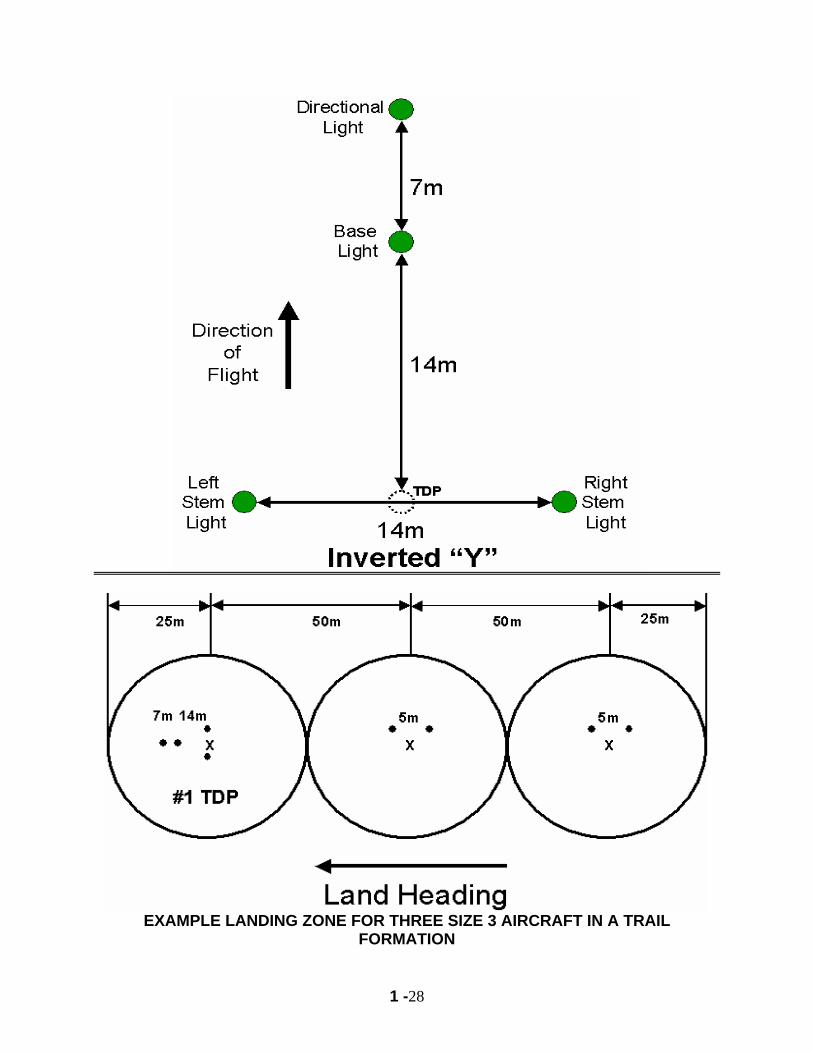
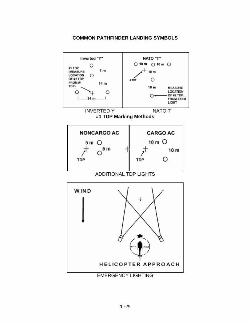
(1) Obstacle ratio- 10:1 (2) Mark obstacles - red (3) Inverted “Y”: 7m x 14m x 14m. Directional light, Base light, left and
right stem lights, used to mark #1 TDP at night. NO red (4) Additional TDP’s: - Size 3: 5m x 5m- for observation and utility A/C
- Size 4: 10m x 10m- used for sling load A/C and cargo A/C (5) Separate A/C that require a different landing point size by 100m.
6. CONTROLLING PHASE
a. Visual b. Electronic c. Verbal
7. WHEN ESTABLIHING AN LZ:
a. Establish control facilities: (1) Must have “Ground To Air” communications (GTA) (2) Must be able to observe the entire PZ/LZ
b. Determine length and width of LZ/PZ: Pace both and make a record of it
1 -25
c. Determine area of unusable: (1) 10:1 ratio, straight edge method (2) #1 TDP at edge of unusable
d. Obstacles: Four “R”s: Remove, Reduce, mark with Red, Radio advisory to pilot.
e. Mark and clear TDP’s: a. VS 17 panel during daylight b. Inverted “Y” at night c. Clear the PZ/LZ using “zig-zag” method in each cardinal direction
TECHNICAL FACTORS IN PZ AND LZ SELECTION
1 -26
TECHNICAL FACTORS IN PZ AND LZ SELECTION (CONT’D)
1 -27
GROUND SLOPE
1 -28
EXAMPLE LANDING ZONE FOR THREE SIZE 3 AIRCRAFT IN A TRAIL
FORMATION
1 -29
COMMON PATHFINDER LANDING SYMBOLS
INVERTED Y NATO T
#1 TDP Marking Methods
ADDITIONAL TDP LIGHTS
EMERGENCY LIGHTING
1 -30
AIRCRAFT FORMATIONS
AIRCARAFT ARE SPACED ACCORDING TO LANDING POINT SIZE
1 -31
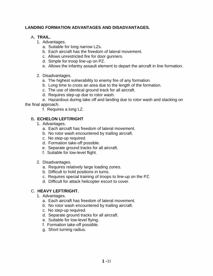
LANDING FORMATION ADVANTAGES AND DISADVANTAGES. A. TRAIL. 1. Advantages. a. Suitable for long narrow LZs. b. Each aircraft has the freedom of lateral movement. c. Allows unrestricted fire for door gunners. d. Simple for troop line-up on PZ. e. Allows the infantry assault element to depart the aircraft in line formation. 2. Disadvantages.
a. The highest vulnerability to enemy fire of any formation. b. Long time to cross an area due to the length of the formation. c. The use of identical ground track for all aircraft. d. Requires step-up due to rotor wash. e. Hazardous during take off and landing due to rotor wash and stacking on the final approach. f. Requires a long LZ. B. ECHELON LEFT/RIGHT 1. Advantages. a. Each aircraft has freedom of lateral movement. b. No rotor wash encountered by trailing aircraft. c. No step-up required. d. Formation take-off possible.
e. Separate ground tracks for all aircraft. f. Suitable for low-level flight. 2. Disadvantages. a. Requires relatively large loading zones. b. Difficult to hold positions in turns. c. Requires special training of troops to line-up on the PZ. d. Difficult for attack helicopter escort to cover. C. HEAVY LEFT/RIGHT. 1. Advantages. a. Each aircraft has freedom of lateral movement. b. No rotor wash encountered by trailing aircraft. c. No step-up required. d. Separate ground tracks for all aircraft. e. Suitable for low-level flying. f. Formation take-off possible. g. Short turning radius.
1 -32
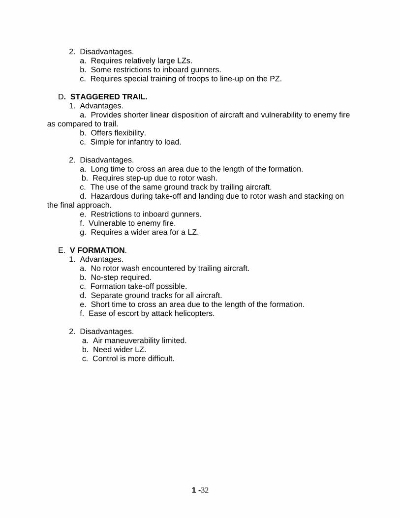
2. Disadvantages. a. Requires relatively large LZs. b. Some restrictions to inboard gunners. c. Requires special training of troops to line-up on the PZ. D. STAGGERED TRAIL. 1. Advantages. a. Provides shorter linear disposition of aircraft and vulnerability to enemy fire as compared to trail. b. Offers flexibility. c. Simple for infantry to load. 2. Disadvantages. a. Long time to cross an area due to the length of the formation.
b. Requires step-up due to rotor wash. c. The use of the same ground track by trailing aircraft. d. Hazardous during take-off and landing due to rotor wash and stacking on the final approach. e. Restrictions to inboard gunners. f. Vulnerable to enemy fire. g. Requires a wider area for a LZ. E. V FORMATION. 1. Advantages. a. No rotor wash encountered by trailing aircraft. b. No-step required. c. Formation take-off possible. d. Separate ground tracks for all aircraft. e. Short time to cross an area due to the length of the formation. f. Ease of escort by attack helicopters. 2. Disadvantages. a. Air maneuverability limited. b. Need wider LZ. c. Control is more difficult.
1 -33
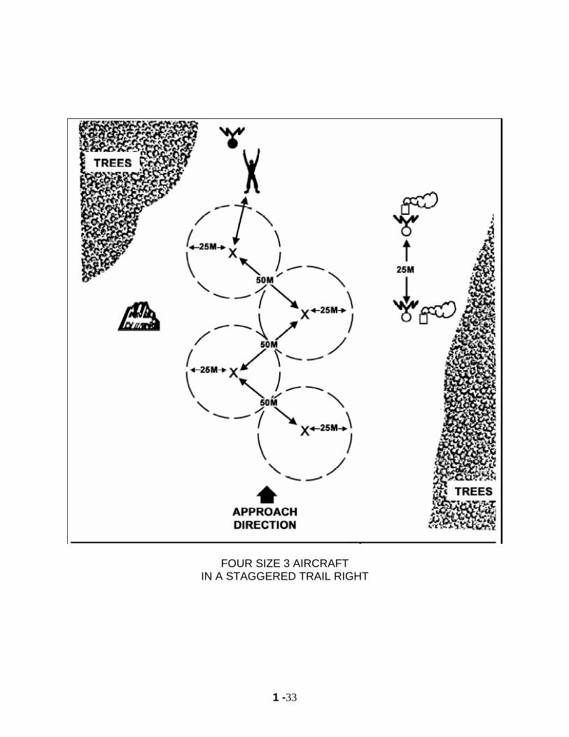
FOUR SIZE 3 AIRCRAFT IN A STAGGERED TRAIL RIGHT
1 -34
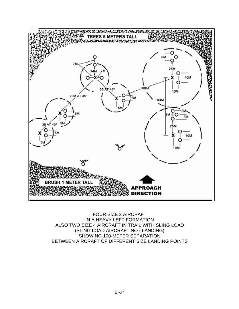
FOUR SIZE 2 AIRCRAFT IN A HEAVY LEFT FORMATION
ALSO TWO SIZE 4 AIRCRAFT IN TRAIL WITH SLING LOAD (SLING LOAD AIRCRAFT NOT LANDING)
SHOWING 100-METER SEPARATION BETWEEN AIRCRAFT OF DIFFERENT SIZE LANDING POINTS

1 -35
NOTES
1 -36
PART V
HAND AND ARM SIGNALS:
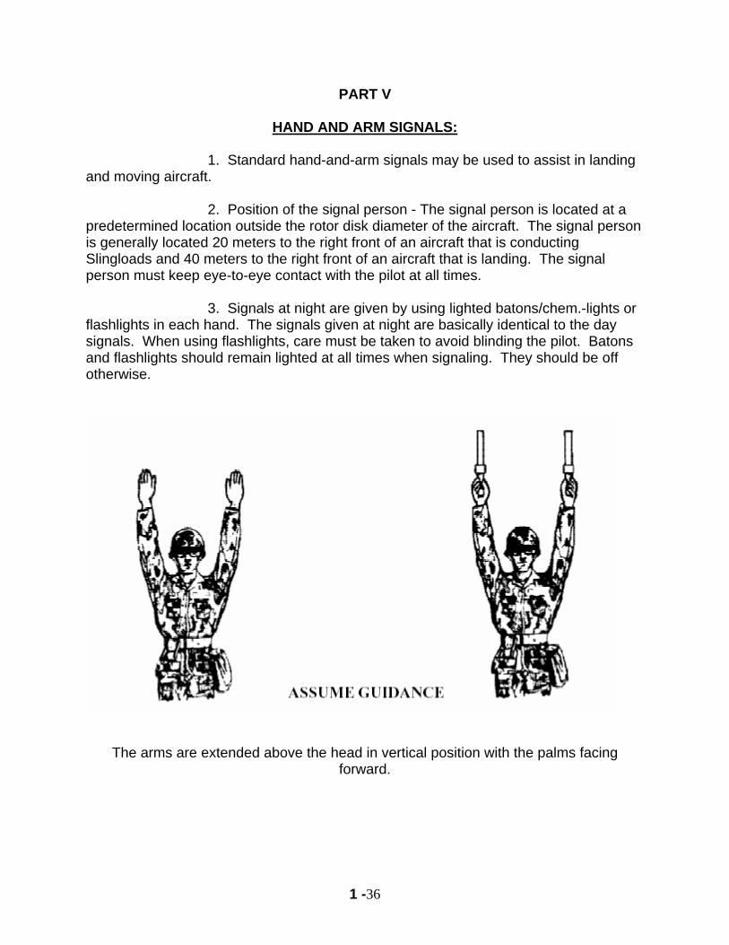
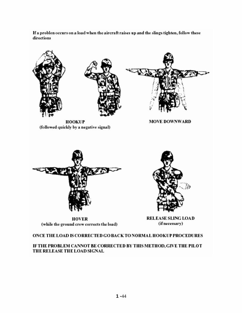
1. Standard hand-and-arm signals may be used to assist in landing and moving aircraft. 2. Position of the signal person - The signal person is located at a predetermined location outside the rotor disk diameter of the aircraft. The signal person is generally located 20 meters to the right front of an aircraft that is conducting Slingloads and 40 meters to the right front of an aircraft that is landing. The signal person must keep eye-to-eye contact with the pilot at all times. 3. Signals at night are given by using lighted batons/chem.-lights or flashlights in each hand. The signals given at night are basically identical to the day signals. When using flashlights, care must be taken to avoid blinding the pilot. Batons and flashlights should remain lighted at all times when signaling. They should be off otherwise.
The arms are extended above the head in vertical position with the palms facing forward.
1 -37
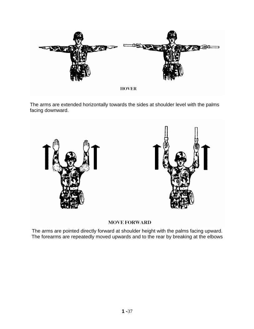
The arms are extended horizontally towards the sides at shoulder level with the palms facing downward.
The arms are pointed directly forward at shoulder height with the palms facing upward. The forearms are repeatedly moved upwards and to the rear by breaking at the elbows
1 -38
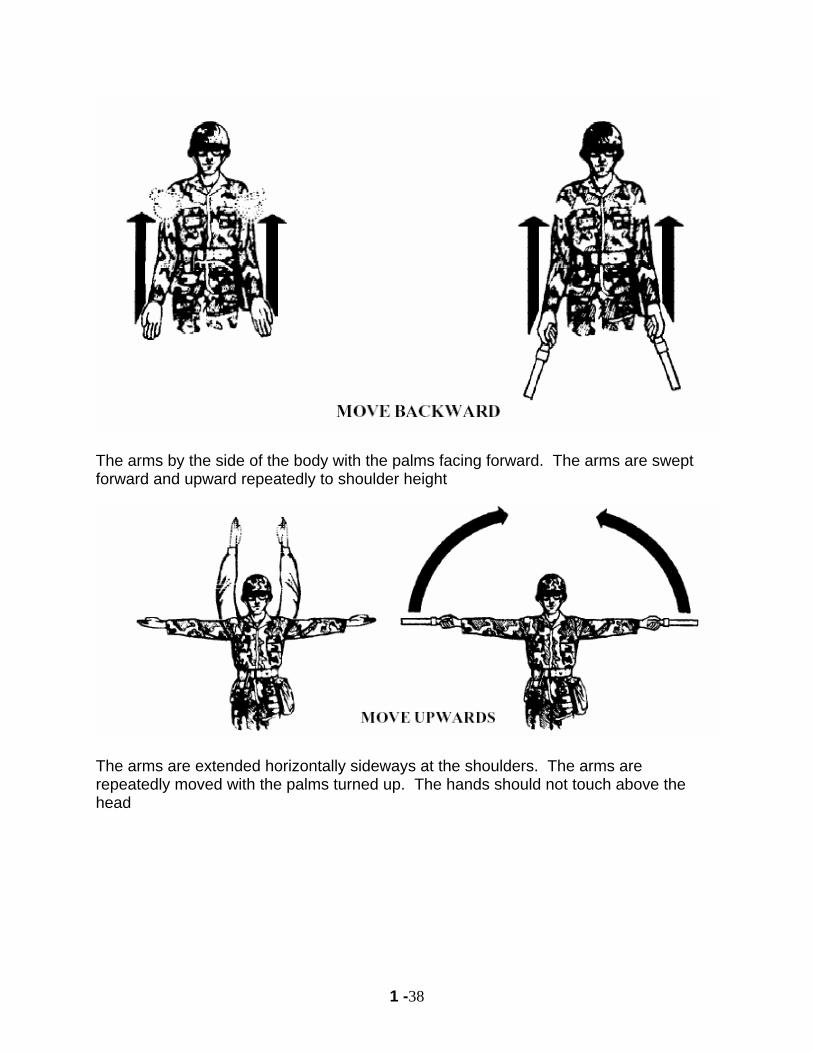
The arms by the side of the body with the palms facing forward. The arms are swept forward and upward repeatedly to shoulder height
The arms are extended horizontally sideways at the shoulders. The arms are repeatedly moved with the palms turned up. The hands should not touch above the head
1 -39
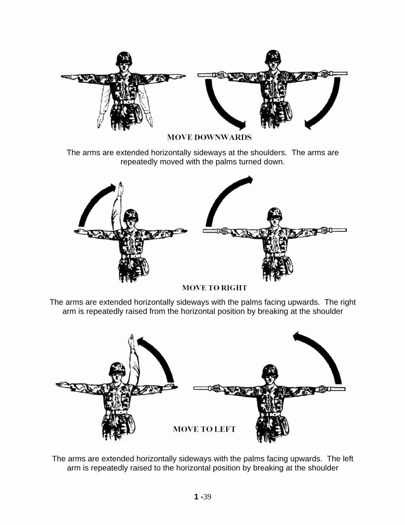
The arms are extended horizontally sideways at the shoulders. The arms are
repeatedly moved with the palms turned down.
The arms are extended horizontally sideways with the palms facing upwards. The right
arm is repeatedly raised from the horizontal position by breaking at the shoulder
The arms are extended horizontally sideways with the palms facing upwards. The left arm is repeatedly raised to the horizontal position by breaking at the shoulder
1 -40
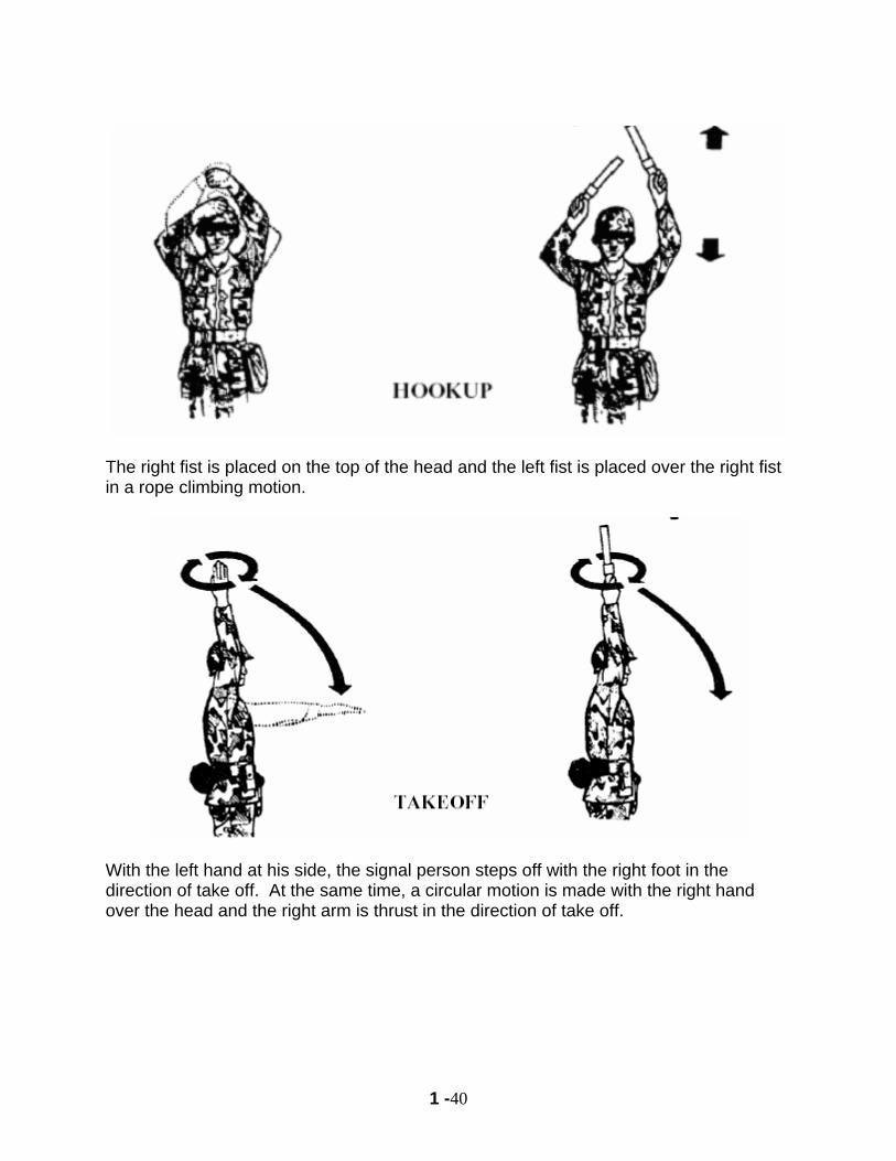
The right fist is placed on the top of the head and the left fist is placed over the right fist in a rope climbing motion.
With the left hand at his side, the signal person steps off with the right foot in the direction of take off. At the same time, a circular motion is made with the right hand over the head and the right arm is thrust in the direction of take off.
1 -41
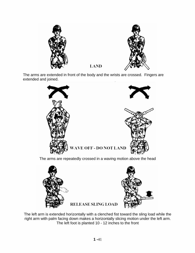
The arms are extended in front of the body and the wrists are crossed. Fingers are extended and joined.
The arms are repeatedly crossed in a waving motion above the head
The left arm is extended horizontally with a clenched fist toward the sling load while the right arm with palm facing down makes a horizontally slicing motion under the left arm.
The left foot is planted 10 - 12 inches to the front
1 -42
1 -43
1 -44

1 -45
NOTES
1 -46
PART VI
COMBAT ASSAULT REFERENCES: FM 90-4 Air Assault Operations DEFINITION: Air Assault: Operations in which air assault forces (combat, combat support, and combat service support), using the firepower, mobility, and total integration of helicopter assets in their ground or air roles, maneuver on the battlefield under the control of the ground or air maneuver commander to engage and destroy enemy forces or to seize and hold key terrain. Air Movement Operations are those operations involving the use of Army airlift assets for other than Air Assaults. CAPABILITIES. Include: 1. Attack enemy from any direction 2. Delay a much larger force 3. Over fly or bypass barriers, obstacles or enemy positions. 4. Conduct deep attacks and raids well beyond the FLOT 5. Rapidly secure and defend key terrain LIMITATIONS. Include: 1. Adverse weather 2. LZ/PZ availability 3. Initial reliance on air re-supply & lines of communication 4. High fuel and ammunition consumption 5. Reduced ground mobility after insertion VULNERABILITIES. Include: 1. Attack by ground, air, artillery on PZ/LZ 2. Attack by A/C or ADA during movement 3. Attack by NBC 4. Electronic warfare 5. Small arms fire TACTICAL EMPLOYMENT 1. Mass or shift combat power rapidly 2. Use of surprise 3. Flexibility, mobility, speed 4. Gain and maintain initiative 5. Extending depth, width of battlefield with little regard to terrain
1 -47
AIR ASSAULT TASK FORCE A. INDIVIDUAL UNITS 1. INFANTRY: Nucleus of AIR ASSSULT TASK FORCE 2. AVIATION: Attack, assault and recon aircraft under the control of the AATF CDR. 3. ARTILLERY: Provide fire support if contact is made 4. ENGINEER: Emplace/ breach obstacles/ minefields 5. Air Defense Artillery: Ground to air fire support 6. Military Intelligence: Conduct electronic warfare, collect and disseminate information 7. RESERVE: AATF requires fewer reserve forces due to superior mobility, flexibility, and speed 8. COMBAT SUPPORT: Mission specific support B. All units placed under the command of a single command headquarters= Air Assault Task Force Commander (AATFC). Normally an Infantry Commander.
1. DIVISION LEVEL: Lowest level with assets for an Air Assault. 2. BATTALION LEVEL: Lowest level at which an AASLT operation can be planned or coordinated. 3. COMPANY LEVEL: Lowest level with a Command Headquarters to execute an Air Assault Operation
Successful air assault execution is based on a careful analysis of METT-T and detailed, precise, reverse planning. There are five basic plans that comprise the reverse planning sequence. They are developed for each air assault operation FIVE STAGE REVERSE PLANNING SEQUENCE 1. GROUND TACTICAL PLAN: Actions on the objective H-HOUR: Time that first A/C of the first lift touches down on the LZ
All planning times based from H-Hour 2. LANDING PLAN: Actions on the LZ. Must support ground tactical plan. Ensures units arrive at designated locations and times prepared to execute the ground tactical plan. General considerations:
a. Availability, location, and size of LZs b. Elements land with tactical integrity. c. Troops are kept informed of changes. Land prepared to fight in any direction. d. Supporting fires must be planned in and around each LZ. e. The plan includes resupply and medical evacuation by air. f. Alternate LZs should be planned for each primary LZ selected to ensure flexibility
LOAD/UNLOAD: 101st DIV Standard= 2 min to load A/C, 30 sec to offload (troops).
1 -48
3. AIR MOVEMENT PLAN: Actions during flight. a. Based on the ground tactical and landing plans. b. Specifies the schedule & instructions of air movement of troops, equipment, and supplies from PZs to LZs. c. Provides instructions regarding air routes, control points, and aircraft speeds, altitudes, and formations. e. Includes use of attack helicopters.
FLIGHT ROUTES
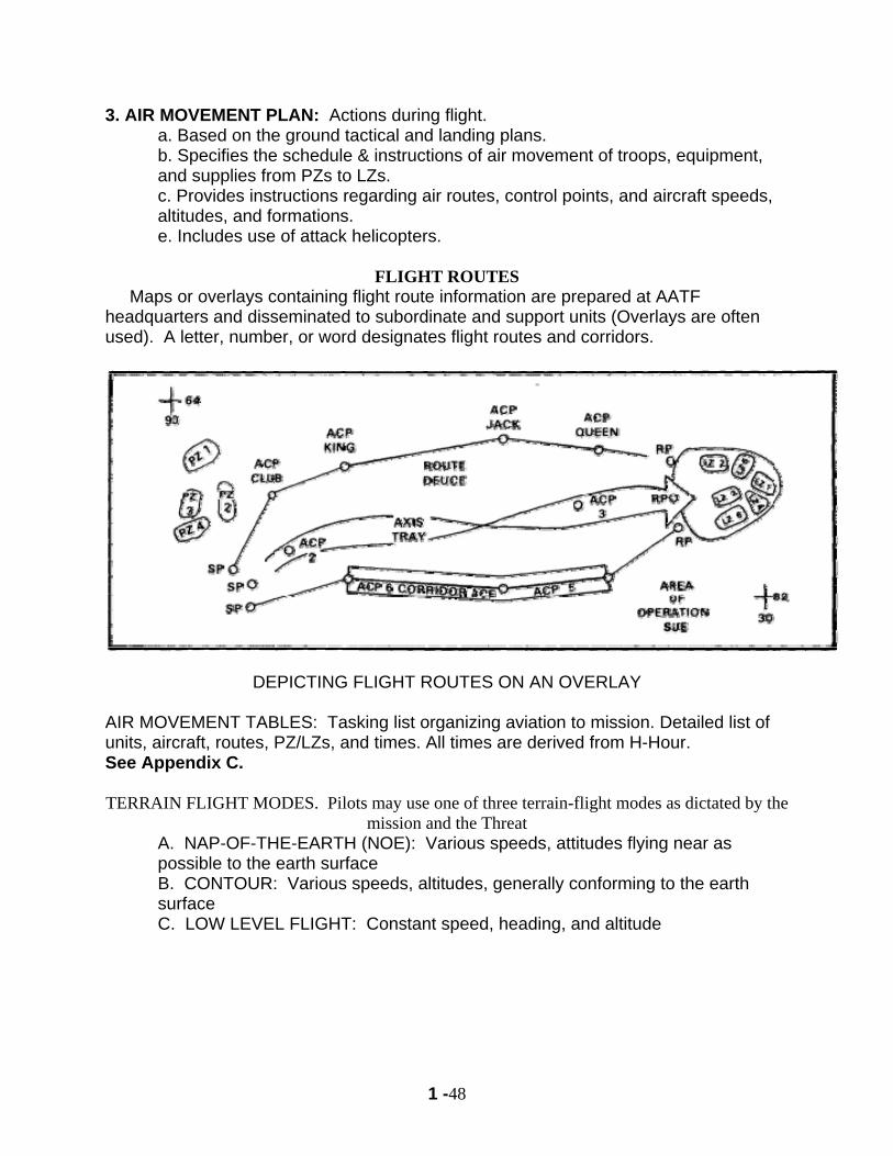
Maps or overlays containing flight route information are prepared at AATF headquarters and disseminated to subordinate and support units (Overlays are often used). A letter, number, or word designates flight routes and corridors.
DEPICTING FLIGHT ROUTES ON AN OVERLAY AIR MOVEMENT TABLES: Tasking list organizing aviation to mission. Detailed list of units, aircraft, routes, PZ/LZs, and times. All times are derived from H-Hour. See Appendix C. TERRAIN FLIGHT MODES. Pilots may use one of three terrain-flight modes as dictated by the
mission and the Threat A. NAP-OF-THE-EARTH (NOE): Various speeds, attitudes flying near as possible to the earth surface B. CONTOUR: Various speeds, altitudes, generally conforming to the earth surface C. LOW LEVEL FLIGHT: Constant speed, heading, and altitude
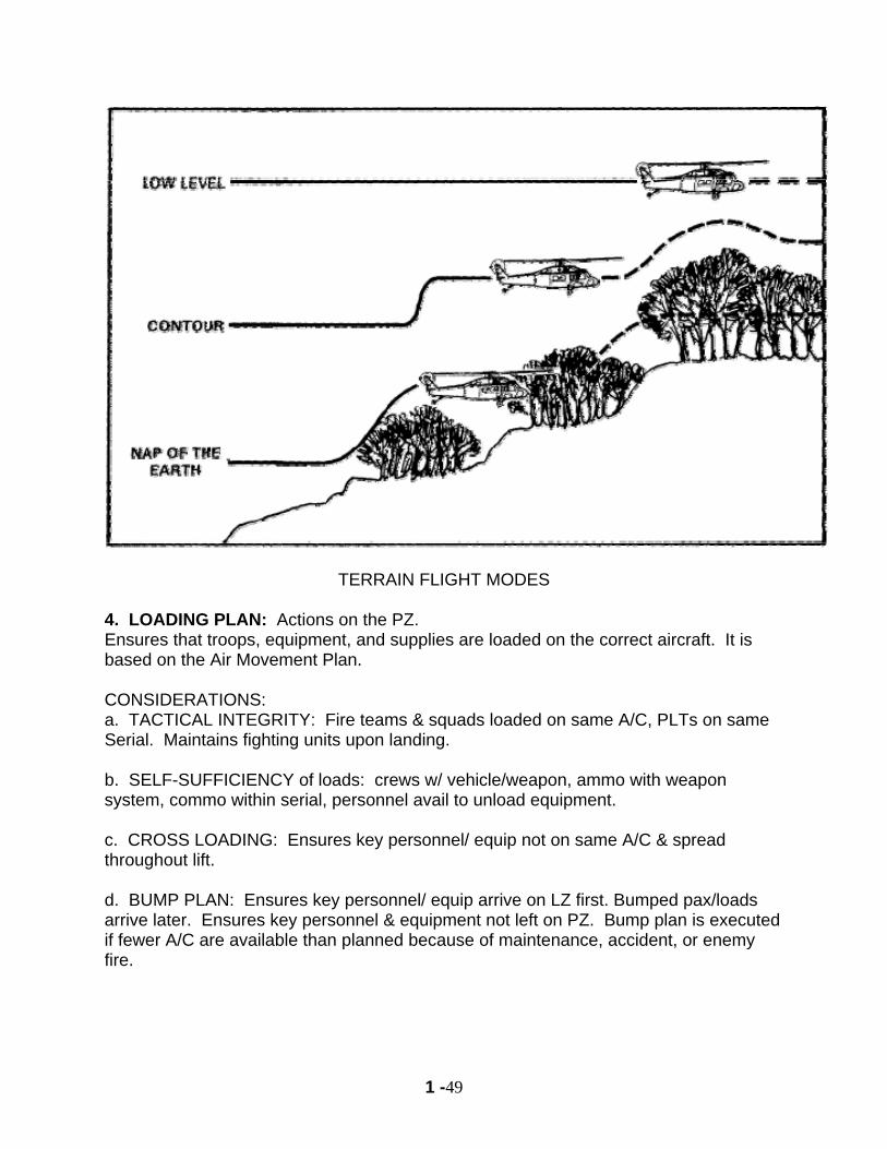
1 -49
TERRAIN FLIGHT MODES 4. LOADING PLAN: Actions on the PZ. Ensures that troops, equipment, and supplies are loaded on the correct aircraft. It is based on the Air Movement Plan. CONSIDERATIONS: a. TACTICAL INTEGRITY: Fire teams & squads loaded on same A/C, PLTs on same Serial. Maintains fighting units upon landing. b. SELF-SUFFICIENCY of loads: crews w/ vehicle/weapon, ammo with weapon system, commo within serial, personnel avail to unload equipment. c. CROSS LOADING: Ensures key personnel/ equip not on same A/C & spread throughout lift. d. BUMP PLAN: Ensures key personnel/ equip arrive on LZ first. Bumped pax/loads arrive later. Ensures key personnel & equipment not left on PZ. Bump plan is executed if fewer A/C are available than planned because of maintenance, accident, or enemy fire.
1 -50
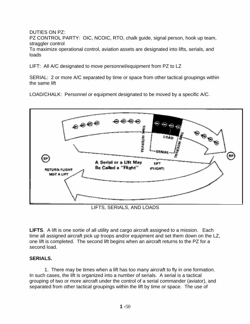
DUTIES ON PZ: PZ CONTROL PARTY: OIC, NCOIC, RTO, chalk guide, signal person, hook up team, straggler control To maximize operational control, aviation assets are designated into lifts, serials, and loads LIFT: All A/C designated to move personnel/equipment from PZ to LZ SERIAL: 2 or more A/C separated by time or space from other tactical groupings within the same lift LOAD/CHALK: Personnel or equipment designated to be moved by a specific A/C.
LIFTS, SERIALS, AND LOADS
LIFTS. A lift is one sortie of all utility and cargo aircraft assigned to a mission. Each time all assigned aircraft pick up troops and/or equipment and set them down on the LZ, one lift is completed. The second lift begins when an aircraft returns to the PZ for a second load. SERIALS. 1. There may be times when a lift has too many aircraft to fly in one formation. In such cases, the lift is organized into a number of serials. A serial is a tactical grouping of two or more aircraft under the control of a serial commander (aviator), and separated from other tactical groupings within the lift by time or space. The use of
1 -51
serials may be necessary to maintain effective control of aviation assets. For example, if a NOE flight were used, it would be difficult to control sixteen aircraft as a single increment. However, a sixteen aircraft lift with four serials of four aircraft with a 2-minute time separation is more easily controlled. 2. Serials may also be required when the capacity of available PZs or LZs is limited. If there is a lift of sixteen aircraft and available PZs and/or LZs will accommodate only four aircraft, it is best to organize into four serials of four aircraft each. 3. Serials are also employed to allow flexibility with flight routes. If there are several acceptable flight routes, the AATFC may choose to employ serials to avoid concentrating his force along one flight route. If the commander wants all his forces to land simultaneously in a single LZ, he does so by having the serials converge at a aerial rally point before landing. With a lift of sixteen aircraft and four available flight routes, the AATFC could use four serials of four aircraft each. Each serial should use a different flight mode. Each time there is a new lift a new serial begins. For example, in lift one there are serials one through four. In lift two, serials again start with one. LOADS. 1. Within each lift there is also a specific number of loads. A load is personnel and/or equipment designated to be moved by a specific aircraft. When planning the air movement, each aircraft is termed a load. For example, within a lift of ten aircraft, the loads are numbered one through ten. For each lift thereafter, the loads remain one through ten. For example, lift one loads are numbered one through ten; next lift is lift two, loads are numbered one through ten. 2. An aircraft load may also be referred to as a “chalk load,” “chalk number,” or a “chalk.” Loads also must be designated within serials just as they are within lifts. Counting within the serials is continuous up to the total number of aircraft in the lift. For example, in a lift of sixteen aircraft with four serials of four aircraft. Serial two’s loads are numbered five through eight. In lift one, serial three, loads are numbered nine through twelve. Finally, in lift one, serial four, loads are numbered thirteen through sixteen (Figure 1-5). 5. STAGING PLAN: Actions prior to mission.
Troops, equipment, and supplies at the PZ in the proper order for movement. Units should be in PZ posture 15 minutes before aircraft arrive.
AIR LOAD TABLE: Detailed tasking list assigning personnel/load to a specific A/C. See Appendix D. AIR MISSION BRIEF: Last meeting of key persons in an AASLT mission. Finalizes details of plan. See Appendix A for AMB Format
1 -52
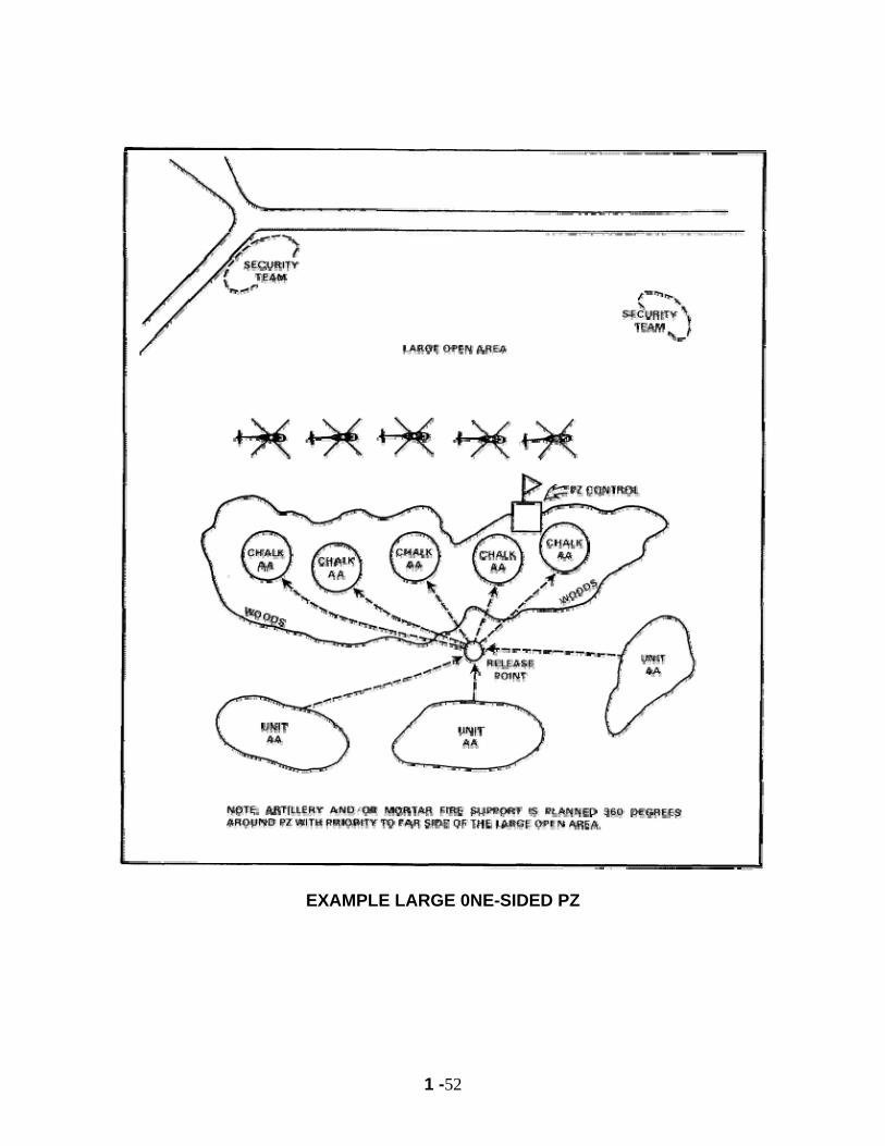
EXAMPLE LARGE 0NE-SIDED PZ

1 -53
NOTES
1 -54
AIR MISSION BRIEFING 1. GENERAL. The air mission briefing (AMB) is the final face-to-face meeting between the ground tactical commander and the aviators flying the mission. It is the last chance to confirm changes and make final coordination. 2. CONTENT. The AMB briefing covers all details for planning and preparation of the mission. The operation is briefed including all five stages, as explained previously, and finally the air movement table is completed. 3. PARTICIPANTS. The AMB should include the key ground and aviation unit personnel. They may include: the ground tactical commander of the unit being inserted, the AMC, S2, S3, fire support officer, aviation liaison officer (LNO), ADA liaisons, aviation unit operations officer, and battle team captains (BTC) from air reconnaissance and attack helicopter units. It may also include the S3 Air, signal officer (SIGO), and the S4. 4. LOCATION. The briefing is conducted at a location specified by the AATFC and is dependent upon the amount of time available before execution of the mission. In determining the location, the factors to consider are as follows: a. Time required to assemble key personnel. b. Availability of information (intelligence and status of the aviation assets). c. Availability of planners. d. Operations security (multiple aircraft in forward battalion locations). e. Vulnerability to enemy observation and fires. 5. TIME. The AMB should be held as soon as possible after the reverse planning sequence is completed. Applying the one-third, two-thirds rule should allow enough time for all element leaders to brief their subordinate units. For example, with a 12-hour warning, the briefing should be conducted eight hours before the first aircraft arrives at the PZ. This allows four hours to plan the operation. 6. AIR MISSION BRIEFING FORMAT. Appendix A is an AMB format. Its use will help ensure that essential information is included in an air assault mission briefings.
1 -55
PLATOON LEVEL ACTIONS FOR AN AIR ASSAULT REFERENCE: FM 90-4 Air Assault Operations
DUTIES AND RESPOSIBILITIES
1. Platoon leader a. Overall responsibility for mission b. Plans operation c. Issue operations order and conducts rehearsals d. Briefs leaders e. Maintains commo with HQ
2. Platoon sergeant a. Overall responsibility for PZ b. Set up PZ c. Briefs chalk leaders d. Devises and disseminates bump plan e. Ensures everything has cleared the PZ f. Rides in last A/C for control purposes
3. Chalk leader a. Ensures his personnel know their tasks & position on the A/C b. Ensures lights or panels for A/C are emplaced c. Assigns area of security to his personnel, supervise area of security d. Supervises everyone on A/C while in flight e. Ensures safe, rapid off loading and security for the A/C f. Ensures no one exits the A/C until told to do so.
1 -56
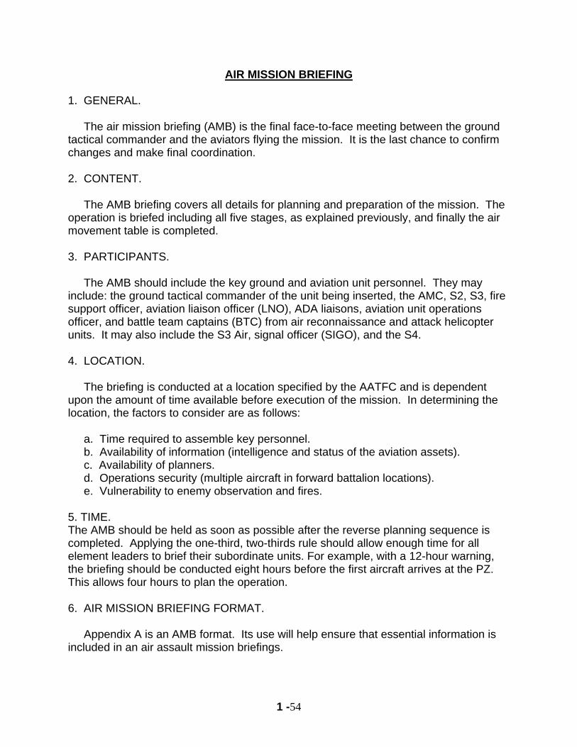
COLD LOAD TRAINING: The KEY to a successful mission.
1. Supervised by chalk leader & unit leadership 2. Conducted prior to PZ posture (can be done on PZ with mission A/C) 3. All personnel must be present, including attachments (medic, FO, translators,
etc). 4. Use equipment that will be on mission 5. Designate:
a. Order of movement to the A/C b. Who will sit where c. Who will open/close door (pri & alt)
6. Chalk leader may lead chalk to A/C, then count them on/off 7. During training, actually open/close doors during both load & unload 8. Coordinate with crew if door will be open/closed when A/C arrive, if doors
open/closed during flight, if open/closed after unload. 9. Line up on PZ in load order. 10. Cold load using the same load plan for mission, i.e.: 1 or 2 door load/unload
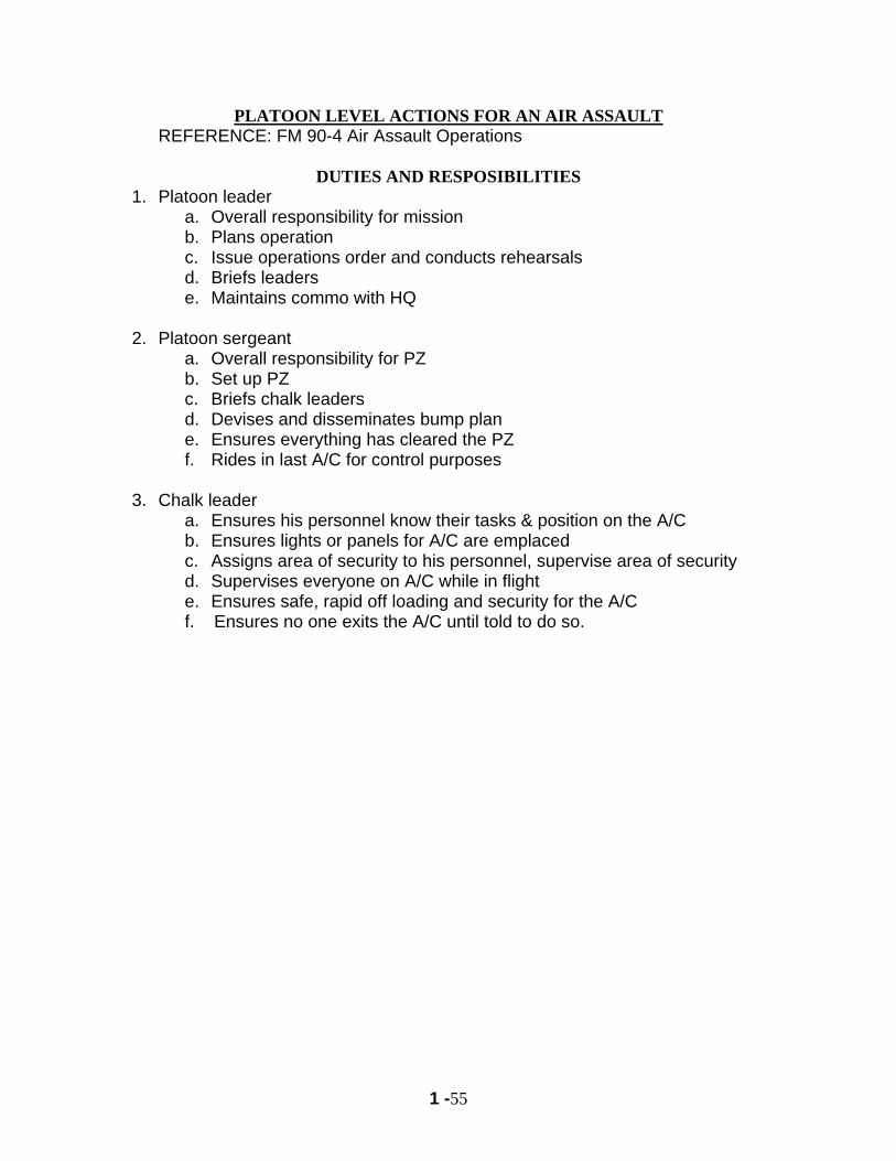
BOTTOM LINE- Rehearse EXACTLY the same way you will execute mission Troop Exit techniques:
1. 3-step drop: Most common. Used when cover is readily avail, or limited visibility (night, brownout).
a. All pax exit A/C from designated door(s) when commanded by Chalk Leader.
b. take approx 3 steps from A/C (approximately 10 meters) c. ensure all equip is cleared from A/C (away from landing wheels) & doors
closed (if reqd). d. drop to prone behind equipment e. place weapon into operation. f. Provide security & Wait for A/C to take off g. Move out tactically to AA or OBJ
2. Right/Left/2 door rush: Used when no cover avail, visibility is good, speed is of the essence, landing on OBJ. Much training reqd.
a. All pax exit A/C from designated door(s) with all equip b. Immediately move away from A/C in tactical formation c. Chalk leader or designated rep ensures all equip is cleared from A/C &
doors closed (if reqd). d. Continue rapid movement from LZ to AA or OBJ e. A/C depart on own
3. One vs Two Door exit or entrance: a. Based on METT-T, training level of troops, direction of OBJ from LZ. b. Two door exit faster, but more difficult control c. One door exit slower, easier control
1 -57
EXAMPLE LOAD SEQUENCE FOR UH-60
EXAMPLE UNLOAD SEQUENCE FOR UH-60
1 -58
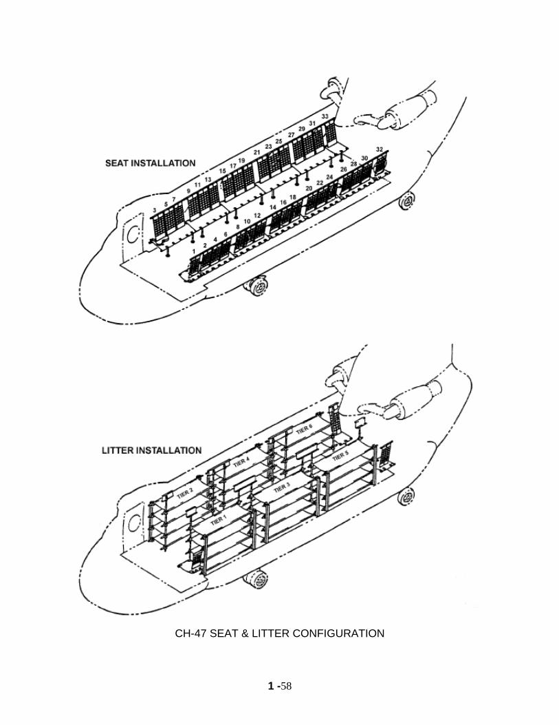
CH-47 SEAT & LITTER CONFIGURATION

1 -59
NOTES
1 -60
PART VII
CLOSE COMBAT ATTACK Reference: FM 3-04.111 (FM1-111) Aviation Brigades, August 2003. 101st Airborne Division (Air Assault) Gold Book, January 2005 1. CCA is a technique to control attack helicopters (AH-64 or OH-58D) in a close air support role, usually very near to friendly troops in contact. It is a method to get the pilot to see the target that you are seeing. It is similar to the Call for Fire for artillery or mortars. The primary difference is that you have to talk to the pilots, who also need to see the target. 2. Steps to control CCA: a. Gain communication with pilot b. Describe your location on the ground and mark it c. Describe the enemy location and mark it
d. After the target is engaged, give the pilot feedback and adjustments (Battle Damage Assessment) 3. Gain communication with pilot
a. Frequency & Callsigns. Request CCA from higher HQ or use pre-arranged frequency. It is preferred that the AVN unit changes to the frequency of the ground unit.
b. Give the pilot a situation report (SITREP) i.e: what the enemy is doing, what type of weapons you are being engaged with, how your friendly forces are arrayed & your actions, the best direction for the pilot to approach from, etc.
c. Pilot should respond with number & type aircraft he is with, number and type weapons available, & how long he can support you (station time).
4. Describe your location on the ground and mark it:
a. The critical aspect is for the pilot to identify your location. Once that happens, you can use your position as a reference for everything else (i.e. the enemy is 180 degrees, 400meters, from my position). Also, it greatly reduces the chance of fratricide.
b. Go from “Big picture” to “small picture.” Best to use grid AND an identifiable terrain feature(s) that aircraft will be able to see, i.e. “I am 2 km Southwest of hill 1450.” Then describe your location from there, and start marking your location.
c. If you can see the aircraft, but they cannot see you, describe your location from them, i.e. “I am at your 3 o’clock, 1500m.”
d. Once the pilot had identified your location, you can usually stop marking unless the pilot requests it, or it has been coordinated otherwise.
1 -61
5. Describe the enemy location and mark it: a. Use multiple methods to describe & mark, i.e. “enemy is vicinity grid
AB123456. From my location- 270 degrees, 500 meters. Marking with IR laser.”
b. Target handover occurs once the pilot had identified your position on the ground and the enemy position. The crew then engages the target while you provide adjustments and feedback to the pilot.
6. The target is engaged and the pilot receives feedback and adjustments (Battle Damage Assessment)
a. Target destroyed- End of Mission b. Target missed- adjust fire (direction & distance in meters from impact to the
target) i.e. “adjust fire, add 200, right 50.” c. Weapon effects on target, re-engage.
7. Common CCA Unit and Target Marking Marking targets for arriving attack aircraft is very difficult. Most CCA occur within 500 meters and may occur within 50 meters of friendly troops. Based on Apache and Kiowa thermal sights and NVGs, the following marking means are available. They are noted for effectiveness for day and night (NVG and thermal): Unit Marking Day Night NVG Night Thermal VS-17 panel go no go no go smoke go no go no go mirror go no go no go IR strobe no go go no go Target Marking Day Night NVG Night Thermal tracer bullets go go no go AN/PAQ-4C no go go no go briefing pointer no go go no go GCP no go go no go M-203 Illum go go go The BEST technique is to have all signals pre-coordinated between the ground and aviation units BEFORE the mission. Additionally, you should have multiple means for marking available, and talk it out over the radio. 8. Bottom Line: CCA cannot be conducted without positive ID of friendly and enemy forces. Both aviation and ground must agree that they know where everybody is before the Apaches/Kiowas open fire.
1 -62
9. Attack Aviation Weapons & Munitions. In order for you to effectively employ attack aviation in CCA, you need to know
what their weapon capabilities are & how they can best support you on the ground. a. 30 mm chain gun
Max Range Max Effective Rg Danger close Burst radius Remarks
4000m 1500m- point 3000m- area 150m 4m
Rate of fire: 600-650 rpm
b. 2.75 inch FFAR
Max Range Max Effective Rg Danger close Burst radius Remarks
9000m 3000-5000m 200m 10m Lethal to 50m c. Hellfire Missile
Max Range Max Effective Rg Danger close Min Range Remarks
8000m 8000m 750m 500m Penetrating
warhead If the enemy is being engaged within the ‘danger close’ range, friendly forces must be behind adequate cover to prevent fratricide. 10. Close Combat Attack request.
Here is what a CCA might sound like on the radio:
Infantry in Contact AH-64 Team Leader Blue Max 6, this is No Slack 6, Fire Mission, over.
No Slack 6, this is Blue Max 6, with 2 AH-64s, 2hrs, 500x 30mm, 58xPD rockets, 4x Hellfire; at IP Charlie. Send Fire Mission.
My location is DF 57898755, marked with IR Strobe.
Target is bunker, 275 degrees at 1000 meters.
Target will be marked with laser pointer Have your position, start target mark. Marking, “If you see the large tree in the field…”. (continue description)
Have your target, stop mark. Engaging with rockets. Roger, Target destroyed, end of mission Roger, Target destroyed, end of mission,
out
1 -63
Example CCA Format *Bold is Aviation Unit Speaking 1. ATTACK UNIT this is Ground unit, request CCA. 2. Ground unit this is ATTACK UNIT is a:
A. Flight of _____ Apaches w/wo goggles, B. _____ min of station time. Requesting:
A. Your grid B. SITREP C. Target description, location, and how marking 3. Ground unit is: A. Located at Grid __ __________
B. SITREP is ____________________________ Over. D. Target from my location is:
1. _____ meters 2. at ____ degrees magnetic 3. Grid __ _________ 4. Marking target with _____________ 4. This is ATTACK UNIT : A. I have positive ID on your location at Grid __ ______ B. Mark target, Over 5. This is Ground unit – Marking target 6. ATTACK UNIT has positively identified target 7. Ground unit Clears Aircraft – ATK UNIT You are clear to engage.” 8. ATTACK UNIT is engaging with (30 / RKTS / MISSLES) 9. ATTACK UNIT this is Ground unit: A. Engagement complete, OR Re-engage target
B. Target Effect is ___________ C. End of mission, Over
10. Ground unit Releases Aircraft – Roger, End of mission, Out.”

1 -64
NOTE
2 - 1
14 CHAPTER TWO
HELICOPTER EXTERNAL LOAD OPERATIONS
PART I GENERAL
1. REFERENCES. a. FM 4-20.197, Multi Service Helicopter Sling Load: Basic Operations and Equipment, July 2006. b. FM 10-450-4, Single-Point Load Rigging Procedures w/ change 3, 3 September 2003. c. FM 10-450-5, Dual-Point Load Rigging Procedures w/ change 3, 3 September 2003. d. TM 10-1670-295-23&P. Technical Manual for 10,000 lb. & 25,000 lb. External Transport Sling Assembly and 5,000 lb. & 10,000 lb. External Transport Cargo Net, dated 22 May 1991. e. FM 90-4, March 1987, Air Assault Operations, March 1987 f. FM 3-21.38 Pathfinder Operations, October 2002 2. INTRODUCTION The helicopter sling load method of carrying cargo and equipment overcomes many of the obstacles that hinder other modes of movement. Helicopters move cargo by external sling load when-- a. The cargo compartment cannot hold the load. b. The load exceeds the helicopter's internal load limitation. c. The ground crew must load or unload the cargo at once. d. Landing zone conditions prevent the aircraft from touching down. 3. EMPLOYMENT CONSIDERATIONS a. Advantages of Sling Load. (1) Allows rapid movement of heavy, outsized equipment, or emergency supplies directly to the user. (2) The rapid relocation of supplies and equipment. (3) The ability to bypass surface obstacles. (4) The use of multiple flight routes and landing sites to enhance sustainability and security of ground units. (5) The establishment of multiple landing sites to support the maneuvering unit requirements. (6) Greater movement flexibility for the ground commander to accomplish the tactical mission. b. Limitations of Sling Load. (1) The weight of the load is restricted to the aircraft’s operating capability. (2) Load instability during flight may restrict aircraft airspeed or maneuvering capabilities. (3) Adverse weather and darkness (low visibility) may limit sling load operations.
2 - 2
(4) Atmospheric conditions (pressure, altitude, temperature, and winds) affect the helicopter’s lift capacity. (5) A limited number of helicopters are available for sling load missions. (6) Landing site surface conditions may restrict helicopter operation. Loose debris, dust, and snow are safety hazards that also limit pilot visibility. (7) Landing site size must be increased during the hours of darkness or reduced visibility to allow the pilot more room to maneuver. 4. AIRCRAFT a. Allowable Cargo Load (ACL) for external loads 1) Actual maximum weight is determined by factors such as fuel in A/C, distance to be flown, density altitude, temperature, altitude, humidity, and airframe. 2) UH-60A: 8000 lbs
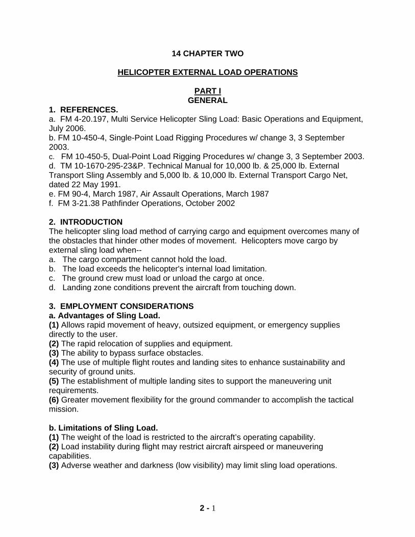
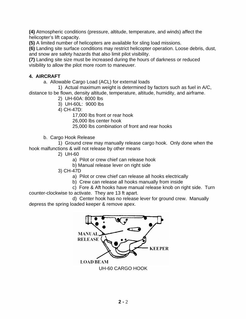
3) UH-60L: 9000 lbs 4) CH-47D: 17,000 lbs front or rear hook 26,000 lbs center hook 25,000 lbs combination of front and rear hooks b. Cargo Hook Release 1) Ground crew may manually release cargo hook. Only done when the hook malfunctions & will not release by other means 2) UH-60 a) Pilot or crew chief can release hook b) Manual release lever on right side 3) CH-47D a) Pilot or crew chief can release all hooks electrically b) Crew can release all hooks manually from inside c) Fore & Aft hooks have manual release knob on right side. Turn counter-clockwise to activate. They are 13 ft apart. d) Center hook has no release lever for ground crew. Manually depress the spring loaded keeper & remove apex.
UH-60 CARGO HOOK
2 - 3
CH 47 CARGO HOOK LOCATIONS CH-47 FORE & AFT HOOKS 5. UNITS. There are normally three different units involved in a sling load operation: supported unit, aviation unit, and receiving unit. Their responsibilities are: a. SUPPORTED UNIT 1. Selecting, preparing, and controlling the PZ. 2. Requisitioning all the equipment needed for sling load operations. 3. Storing, inspecting, and maintaining all sling load equipment.
4. Providing trained ground crews for rigging and inspecting and inspection forms, controlling aircraft, aircraft guides, hooking up loads, and clearing the aircraft for departure.
5. Securing and protecting all sensitive items. 6. Providing load dispositions and instructions to the aviation and receiving unit
for the sling load equipment.
7. Verify the load weight (to include rigging equipment) b. AVIATION UNIT 1. Establish coordination with the supported and receiving units. 2. Advises the supported unit on load limitations.
3. Advises the supported and receiving units on the suitability of selected LZ's and PZ's.
2 - 4
4. Provides assistance in the recovery and return of sling load equipment.
5. Establishes safety procedures and understanding of duties and responsibility between the flight crew and ground crew.
c. RECEIVING UNIT 1. Selects, prepares, and controls the LZ. 2. Provides trained ground crews to guide the aircraft and de-rig the loads.
3. Coordinates with the supporting unit for the control and return of the sling load equipment.
4. Inspects the rigging of back loads (sling load equipment returning to supporting unit).
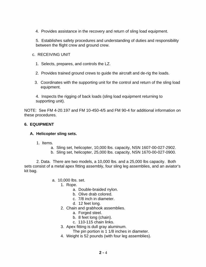
NOTE: See FM 4-20.197 and FM 10-450-4/5 and FM 90-4 for additional information on these procedures. 6. EQUIPMENT A. Helicopter sling sets. 1. Items.
a. Sling set, helicopter, 10,000 lbs. capacity, NSN 1607-00-027-2902. b. Sling set, helicopter, 25,000 lbs. capacity, NSN 1670-00-027-0900.
2. Data. There are two models, a 10,000 lbs. and a 25,000 lbs capacity. Both
sets consist of a metal apex fitting assembly, four sling leg assemblies, and an aviator’s kit bag.
a. 10,000 lbs. set. 1. Rope.
a. Double-braided nylon. b. Olive drab colored. c. 7/8 inch in diameter. d. 12 feet long.
2. Chain and grabhook assemblies. a. Forged steel. b. 8 feet long (chain). c. 110-115 chain links.
3. Apex fitting is dull gray aluminum. The pin portion is 1 1/8 inches in diameter.
4. Weight is 52 pounds (with four leg assemblies).
2 - 5
b. 25,000 lbs. set.
1. Rope. a. Double-braided nylon. b. Black colored. c. 1 1/4 inch in diameter. d. 12 feet long.
2. Chain and grabhook assemblies. a. Forged steel. b. 8 feet long (chain). c. 84-88 chain links.
3. Apex fitting is gold colored steel. The pin portion is 1 1/2inches in diameter.
4. Weight is 114 pounds (with four leg assemblies). 3. Storage.
a. These sling sets should be stored in the aviator's kit bag, which is furnished with each sling set.
b. The kit bag should be stored in a dry place protected from direct sunlight.
4. Inspection.
a. Inspect equipment IAW FM 4-20.197, damage criteria chart in Chapter 6. Inspect before and after every use or every 6 months
b. Inspect metal for rusts, nicks, burrs, cracks, dents, metal distortion, and
proper operation.
c. Inspect nylon portion for grease, oil, and acid, foreign matter. 5. Maintenance. a. Wash off dirt and all substances with a mild detergent or hand soap.
b. After washing, rinse thoroughly and then air dry. Do not wring water out or dry in the sun.
c. Remove corrosion from metal part with a wire brush, emery cloth, or similar
material.
d. Remove burrs or sharp edges from metal parts with a file. 1/8 in dents or metal distortion or missing components will render equipment unserviceable.
e. Replace any defective components.
2 - 6
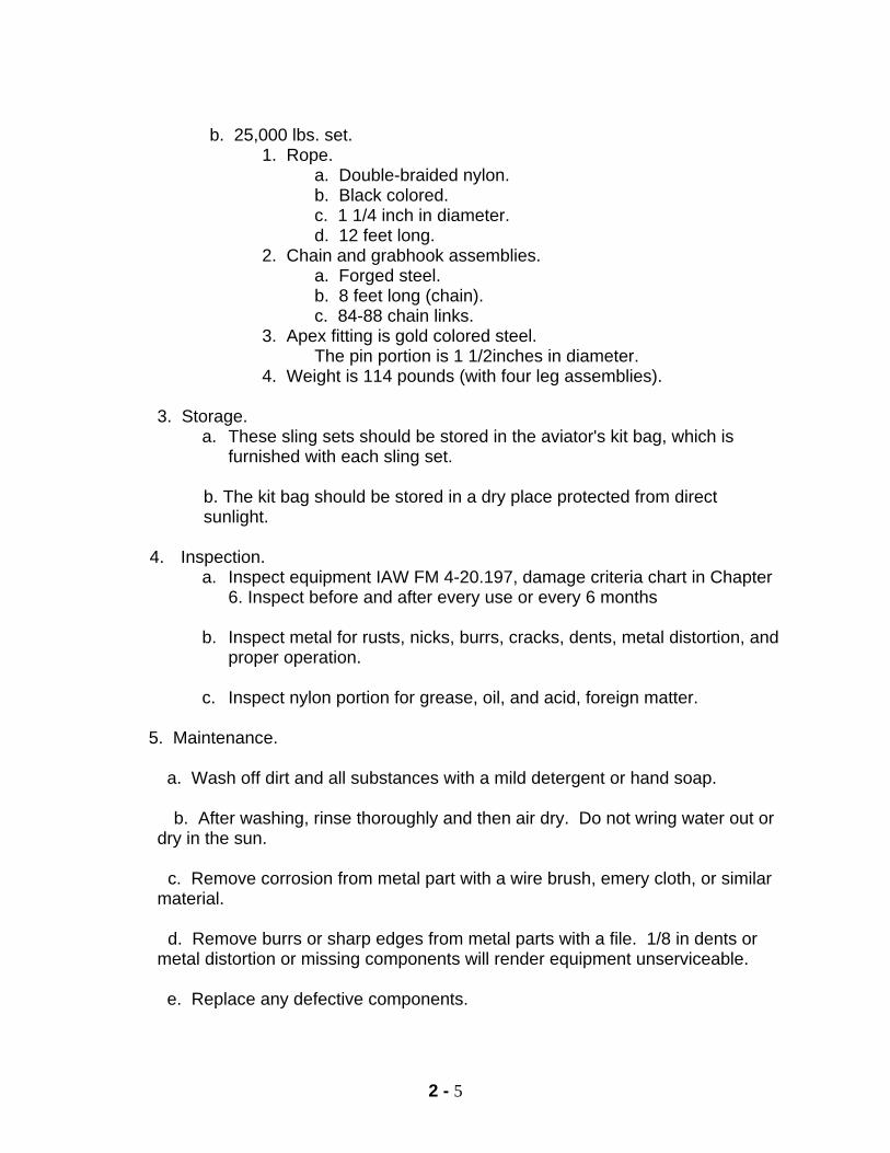
10,000 lb & 25,000 lb Capacity Sling Set Components
B. COMMON ADDITIONAL EQUIPMENT: Required to rig most common loads.
1. Two-inch tape: rated capacity, 80 lbs per wrap. Used to shatterproof glass and plastic surfaces and for padding material. It is also used to secure most excess on loads. Can be used as a breakaway.
2. Type III nylon: Rated Capacity, 550 lbs. Used to secure portions of different
loads. It is round and smooth to the touch.
3. ¼ inch cotton webbing: Rated Capacity: 80 lbs. Used as breakaway material on various loads. Breakaway material prevents sling legs from becoming misrouted or tangled during sling load operations. It is flat and rough to the touch.
2 - 7
4. 3/8 inch hemp rope: Rated Capacity: 3,180 lbs. Used to secure items.
5. 7/16 inch nylon rope: Rated Capacity: 4,500 lbs. Used to secure items, rappelling, and swiss seats.
6. CGU-1B: Rated capacity: 5000 lbs. Used to secure cargo in vehicles and
trailers.
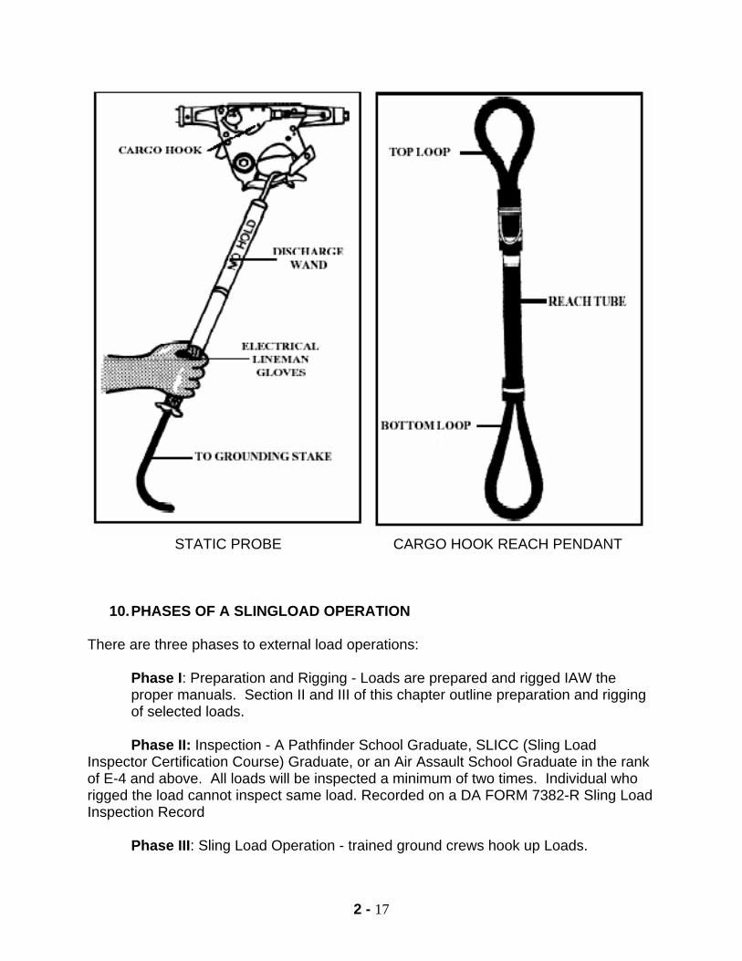
7. Static Probe: Used to protect the hook-up person from static electricity during sling load operations. FM 4-20.197, Appendix D, provides instructions needed to fabricate a field expedient static discharge wand.
8. Cargo Hook Reach Pendant: Rated capacity: 11,000 lbs (Green bottom loop),
25,000 lbs (black bottom loop). The large looped end is attached to the apex and the small looped end is placed into the cargo hook of the aircraft. The cargo hook pendant reach is approved for use with all loads and all aircraft. The CHRP reduces hook up time & gives the hook up team more room & safety. Reach pendants should not be used on loads that have a tendency to spin during flight. A static discharge person is not required when using a reach pendant. (Figure 2-16).
C. OTHER EQUIPMENT: May be required to rig certain certified or unique loads. 1. Clevises
a. Large clevis: rated capacity- 12,500 lbs. Used as a field expedient apex and as a junction point when suspending an accompanying load under a howitzer.
b. Medium clevis: rated capacity- 6,250 lbs. Used on the A-22 cargo bag.
c. Small clevis: rated capacity- 6,250 lbs. Used as a lift point.
d. 5/8 in screw pin clevis: rated capacity- 4,420 lbs. Used as a lift point on
fuel blivits.
e. Small screw pin clevis: rated capacity- 8,650 lbs. Used as a tie down or lift point.
f. Platform clevis: rated capacity: 7,000 lbs. Used on Air Force pallets.
g. Manufactured Apex: rated capacity- 10,000 lbs. Used on 5,000 lbs and
10,000 lbs cargo nets.
2 - 8
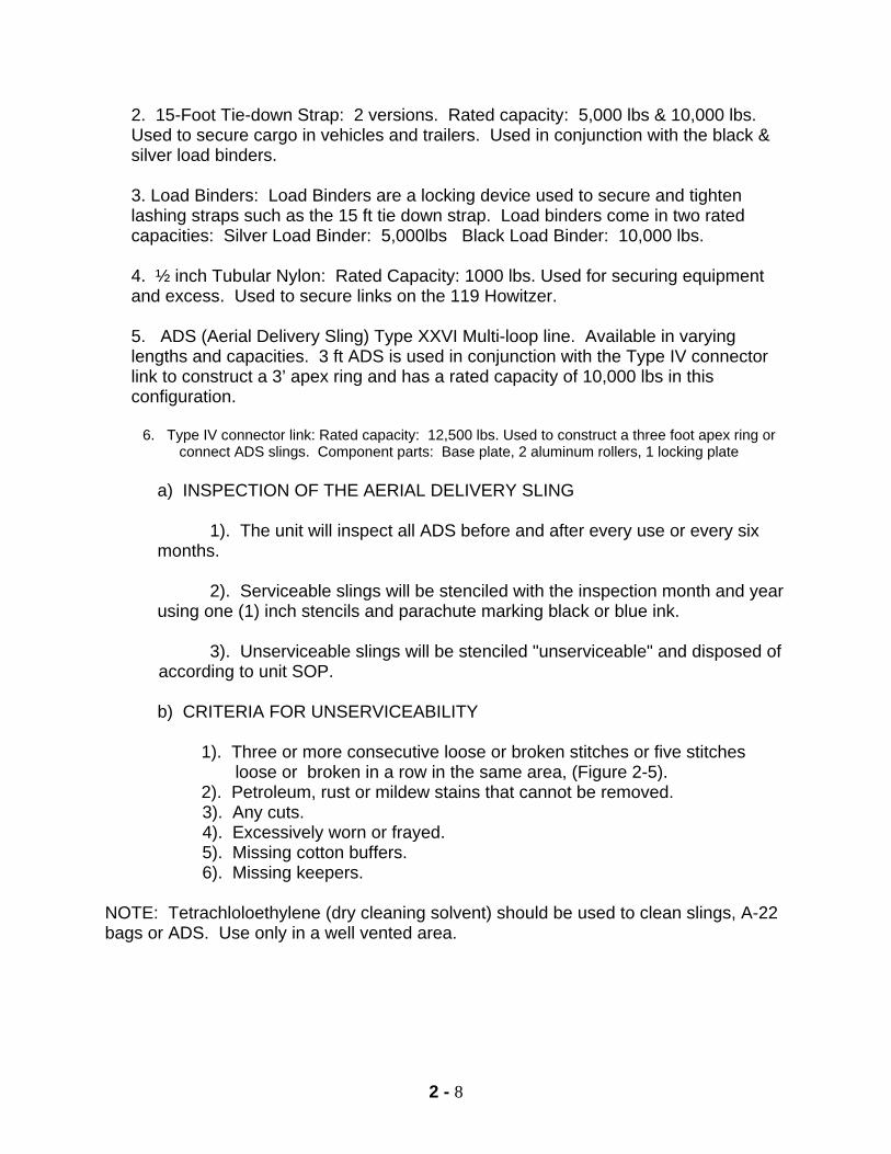
2. 15-Foot Tie-down Strap: 2 versions. Rated capacity: 5,000 lbs & 10,000 lbs. Used to secure cargo in vehicles and trailers. Used in conjunction with the black & silver load binders. 3. Load Binders: Load Binders are a locking device used to secure and tighten lashing straps such as the 15 ft tie down strap. Load binders come in two rated capacities: Silver Load Binder: 5,000lbs Black Load Binder: 10,000 lbs.
4. ½ inch Tubular Nylon: Rated Capacity: 1000 lbs. Used for securing equipment and excess. Used to secure links on the 119 Howitzer.
5. ADS (Aerial Delivery Sling) Type XXVI Multi-loop line. Available in varying lengths and capacities. 3 ft ADS is used in conjunction with the Type IV connector link to construct a 3’ apex ring and has a rated capacity of 10,000 lbs in this configuration.
6. Type IV connector link: Rated capacity: 12,500 lbs. Used to construct a three foot apex ring or
connect ADS slings. Component parts: Base plate, 2 aluminum rollers, 1 locking plate
a) INSPECTION OF THE AERIAL DELIVERY SLING
1). The unit will inspect all ADS before and after every use or every six months.
2). Serviceable slings will be stenciled with the inspection month and year
using one (1) inch stencils and parachute marking black or blue ink.
3). Unserviceable slings will be stenciled "unserviceable" and disposed of according to unit SOP. b) CRITERIA FOR UNSERVICEABILITY
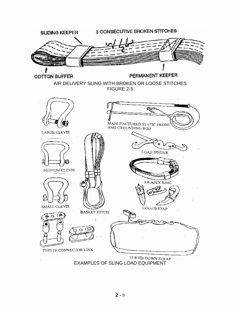
1). Three or more consecutive loose or broken stitches or five stitches loose or broken in a row in the same area, (Figure 2-5).
2). Petroleum, rust or mildew stains that cannot be removed. 3). Any cuts. 4). Excessively worn or frayed. 5). Missing cotton buffers. 6). Missing keepers. NOTE: Tetrachloloethylene (dry cleaning solvent) should be used to clean slings, A-22 bags or ADS. Use only in a well vented area.
2 - 9
AIR DELIVERY SLING WITH BROKEN OR LOOSE STITCHES
FIGURE 2-5
EXAMPLES OF SLING LOAD EQUIPMENT

2 - 10
NOTES
2 - 11
7. PERSONNEL REQUIRED FOR SLINGLOAD OPERATIONS a. General. Three personnel are normally used for the ground crew in external helicopter rations on the PZ/LZ: a signal person, a static probe person and a hookup person. b. Static Probe Equipment.
(1) The static electricity probe consists of an insulated contact rod joined by a length of metallic tape or electrical wire to a ground rod, NSN 1670-01-194-0926. (2) The ground rod is driven into the ground and the hookup team's static probe person holds the contact rod to the cargo hook of the aircraft.
c. Protective Equipment. All ground crew personnel will wear the following equipment:
(1) Kevlar helmet, chinstrap fastened. (2) Goggles. (3) Earplugs. (4) Gloves. (5) Sleeves rolled down and buttoned.
d. Ground Crew Emergency Procedures. In an emergency, the ground crew will move to a pre-designated rendezvous point identified by prior coordination with the aviation unit. e. Hookup Procedures.
(1) General. The aircraft approaches the hookup site and is guided into position over the load by the signal person. The static probe person discharges the static electricity from the aircraft cargo hook. The hookup person then attaches the apex fitting to the aircraft cargo hook. (2) Duties of the Hookup Team.
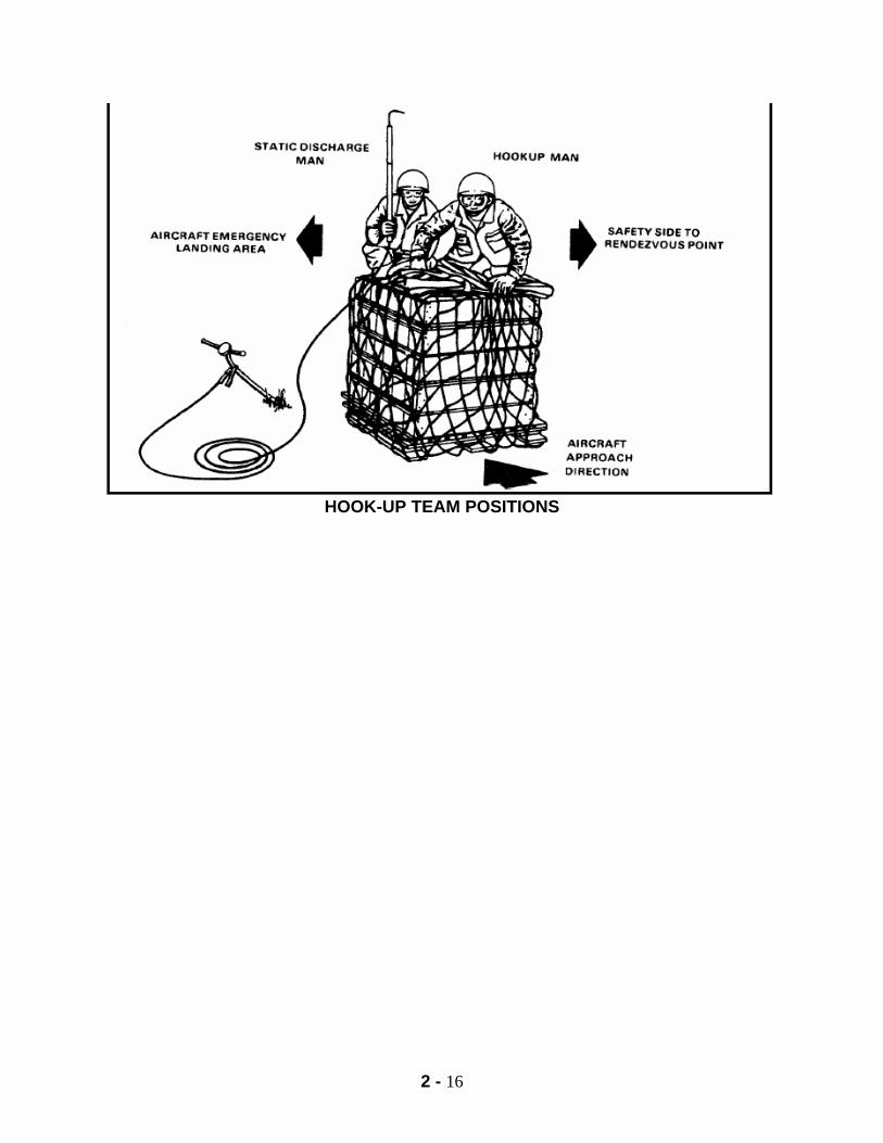
a. Before the arrival of the aircraft, the signal person directs the spotting of the sling load for hookup, inspects the load to ensure that the slings are not fouled and ensures that the load is ready for hookup. b. Prior to the aircraft approaching the hookup site, the hookup team dons their protective equipment and the signal person positions himself at the pre-coordinated location so that he maintains eye-to-eye contact with the pilot. He must stay outside of the rotor disk diameter of the aircraft at all times. The hookup team will position themselves next to the load on the assembly area side. The hookup person will stand next to the load, with the sling legs between the load and themselves. They will hold the bell portion of the apex high above their head and will ensure the pin portion of the apex is skyward and the sling legs are not routed or tangled around their body. The static probe person stands next to the hookup person, closest to the assembly area. The static probe person will
2 - 12
wrap their arm around the waist of the hookup person for added stability. With their outside hand, the static probe person will hold the static probe high above their head. c. The signal person must station himself so that the pilot can plan his approach on him He remains in this position unless terrain features or obstructions prevent an upwind approach. If this occurs, the signal person observes the approaching helicopter and moves to a position, which will allow the pilot to guide in on him. As the pilot maneuvers the aircraft into the wind, the signal person adjusts his position to remain to the front of the aircraft and in view of the pilot. d. The signal person guides the aircraft until the aircraft is approximately centered over the load. The signal person gives the hand and arm signal of hover. At this time, the pilots will use the signal person as a reference point. The crew chief or flight engineer will guide the aircraft over the load. e. Once the cargo hook is within reach, the static probe person will place the static probe into the cargo hook of the aircraft discharging all static electricity. The static probe person will maintain constant contact with the cargo hook. The hookup person will then place the pin portion of the apex into the cargo hook of the aircraft. The hookup person will ensure the pin portion of the apex is seated properly, and will release the apex. At this time, the static probe can be removed from the cargo hook. Both the static probe person and the hook up person will then police up the static probe and double time toward the assembly area. Once they are a safe distance outside the rotor disk diameter of the aircraft, they will turn, face the load, and kneel. When the hookup team is clear of the aircraft, the signal person gives the pilot the "hookup complete" signal, then the "move upward" signal. This signal is given so that the aircraft rises slowly taking up slack in the slings, and the load is six to eight inches off the ground. The signal person is alert to ensure that the sling legs are not fouled and the load is properly attached to the cargo hook. If the legs are fouled or if the load is improperly suspended, the signal person gives the "move downward" signal and directs the release of the load. The hookup person and the static probe person will conduct an inspection of the load from their position. If everything looks proper and the load appears safe to fly, they will give the "thumbs up" signal to the signal person. After the signal person ensures the loads correctly suspended, he gives the pilot the "takeoff" signal.
f. Release Procedures.
1. General. The aircraft approaches the release site and is guided into position by the signal person. The hookup release team stands by, but is not actively employed unless the slings cannot be released from the aircraft. Normally, the ground crew consists of one signal person and two release personnel. 2. Duties of the Signal person.
2 - 13
a. As the aircraft approaches the cargo release site, the signal person
positions himself as he would for a hook-up. b. Using appropriate hand and arm signals, the signal person guides the pilot
in maneuvering the aircraft until the sling load is positioned a few feet above the cargo release points. He directs a gentle lowering of the aircraft until the load rests firmly on the ground.
c. After the cargo load is safety landed and there is slack in the sling legs the signal person gives the pilot the "release sling load" signal.
d. The signal person ensures that the load is properly on the ground and that the sling load is released entirely from the hook.
e. When the load is free of the hook, the signal person gives the pilot the "takeoff" signal.
3. Duties of the Release Team.
a. Prior to the aircraft approaching the cargo release site, the release team dons protective equipment and moves to their pre-coordinated positions. The cargo release team remains in this position unless directed by the signal person to move under the aircraft and manually release the load from the fouled or jammed cargo hook.
b. If directed by the signal person, both soldiers move in under the helicopter.
c. The soldier handling the static electricity probe grounds the cargo hook by contacting it with the probe, then grabs the hook.
d. The second soldier manually operates the cargo hook release or disengages the fouled sling from the hook. If required, both solders work to accomplish cargo release.
e. When the sling load is released from the hook, the soldiers move quickly aside of the aircraft take-off path.
f. Night Operations- Greater care and thorough planning must be taken for night operations. The signal person will use baton flashlights and the release team will carry flashlights
2 - 14
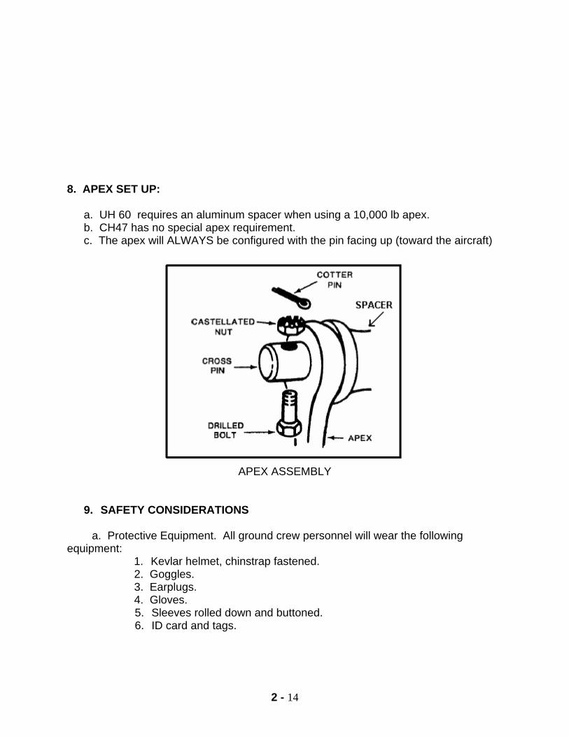
8. APEX SET UP:
a. UH 60 requires an aluminum spacer when using a 10,000 lb apex. b. CH47 has no special apex requirement. c. The apex will ALWAYS be configured with the pin facing up (toward the aircraft)
APEX ASSEMBLY
9. SAFETY CONSIDERATIONS
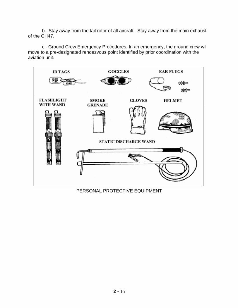
a. Protective Equipment. All ground crew personnel will wear the following equipment:
1. Kevlar helmet, chinstrap fastened. 2. Goggles. 3. Earplugs. 4. Gloves.
5. Sleeves rolled down and buttoned. 6. ID card and tags.
2 - 15
b. Stay away from the tail rotor of all aircraft. Stay away from the main exhaust of the CH47.
c. Ground Crew Emergency Procedures. In an emergency, the ground crew will
move to a pre-designated rendezvous point identified by prior coordination with the aviation unit.
PERSONAL PROTECTIVE EQUIPMENT
2 - 16
HOOK-UP TEAM POSITIONS
2 - 17
STATIC PROBE CARGO HOOK REACH PENDANT
10. PHASES OF A SLINGLOAD OPERATION There are three phases to external load operations:
Phase I: Preparation and Rigging - Loads are prepared and rigged IAW the proper manuals. Section II and III of this chapter outline preparation and rigging of selected loads.
Phase II: Inspection - A Pathfinder School Graduate, SLICC (Sling Load Inspector Certification Course) Graduate, or an Air Assault School Graduate in the rank of E-4 and above. All loads will be inspected a minimum of two times. Individual who rigged the load cannot inspect same load. Recorded on a DA FORM 7382-R Sling Load Inspection Record Phase III: Sling Load Operation - trained ground crews hook up Loads.
2 - 18
PART II CERTIFIED SLINGLOADS
1. GENERAL. All procedures outlined in this chapter are in accordance with FM 4-20.197 and FM 10-450-4 & 5. Additional safety requirements have been added to the preparation and rigging procedures outlined in the reference material. Inspection sequences discussed in this chapter are the recommended procedures for use at The Air Assault School. GENERAL RIGGING INSTRUCTIONS
a. Preparation. The preparation steps are intended to reduce the possibility of damage to the equipment caused by sling leg entanglement during the hookup and lift-off operation or by wind resistance encountered during the flight. Since these preparation steps are not directive in nature, the commander assumes responsibility for any damage to the equipment caused by deviation from the preparation steps. Typical preparation instructions will provide information to secure loose items, remove or secure canvas covers, and remove obstructions, such as antennas. Place protective padding on windshields and other components that could be damaged by the metal parts of the sling set during hookup or release. The load should be secure enough to withstand winds in excess of 120 knots caused by the forward airspeed of the aircraft. If possible, position the load in the takeoff direction so the pilot does not have to pick the load up and then turn the aircraft into the takeoff direction.
b. Rigging. The rigging steps give information as to the position of the apex
fitting on the load, routing orientation of the sling legs, location of the lift provisions, chain link number for each sling leg, and steps required to prevent the sling legs from becoming entangled on the load. Do not change the chain link number in the rigging procedures under any circumstances as it may change sling leg loading and cause lift provision failure.
c. Breakaway safety ties. Used to temporarily restrain the sling legs to
keep them from becoming entangled on the load as the helicopter lifts the load. These safety ties are made of Type I, 1/4-inch cotton webbing or 2” (duct) tape.
d. View of the Load. Left, right, front, and rear directions are designated
from the driver’s perspective for vehicles and towed equipment. Howitzer gun tubes are considered the front of the load. To improve flight stability, some loads are transported backwards. Do not confuse the front of the load as it is carried with the end designated as the front for rigging purposes.
2 - 19
e. Sling Load Inspection Record. Load verified as safe by a qualified inspector.
(1) Give a copy to the supporting aviation unit. (not necessarily the pilot) (2) Securely tape or tie a copy to the load. (3) Give a copy to the supported unit.
f. Factors of In-flight Stability
1). Proper weight. a) Minimum weight for any sling load is 500 lbs.
b) The maximum weight cannot exceed the lift capacity or the hook tensile strength of the aircraft.
2) Proper drag surface.
a) Load must be as aerodynamic as possible b) Balanced loads fly best when level c) Unbalanced loads must have a nose (heavy end) down attitude
which is achieved by the proper link count.
3) Proper air speed. Determined by the Aviation Unit Commander or, in his/her absence, the pilot in command.
4) To improve in-flight stability:
a. Increase weight of load b. Redistribute weight (load plan) c. Alter drag surface (link count) d. Install drogue chute e. Reduce airspeed (least preferred)

2 - 20
NOTES
2 - 21
CARGO NETS 5,000 AND 10,000 POUND CAPACITY
1. LOAD DESCRIPTION. Cargo Net, 5,000 lbs. and 10,000 lbs a. Characteristics: 5,000 lbs. capacity
1. Weight- 58 lbs 2. Size- 15 ft x 15 ft 3. Load zone- 5 ft 4. Mesh size- 6 in 5. Color- OD Green (when new)
b. Characteristics: 10,000 lbs. capacity: 1. Weight- 96 lbs. 2. Size- 18 ft x 18 ft 3. Load zone- 6 ft 4. Mesh size- 7.5 in 5. Color- Black (when new)
2. MATERIALS. a. Sling set with one to four sling legs dependent on load weight. b. One 5,000 lbs. or 10,000 lbs. capacity cargo net. c. Tape, adhesive, pressure-sensitive, 2 inch wide roll. d. Webbing, cotton, 1/4 inch, 80 lbs. breaking strength. e. Minimum of 12 feet, 7/16 inch nylon rope OR an A7A strap. 3. PERSONNEL. Four personnel can prepare and rig this load in 5 minutes.
PHASE I (PART 1)
PREPARATION
1. To prepare the cargo net, you must first lay it out flat on the ground. You will then place your cargo in the net so that 75% or more of the cargo is inside of the yellow border cord. Ensure you have a minimum weight of 500 lbs. 2. Now, pull the net up around the sides of the load ensuring all slack is pulled tight. Next, thread a piece of the 7/16 or 3/8 nylon or hemp rope (or A7A strap) through the web portion of the net. Tighten the rope so that the hole created is smaller than the smallest object inside the net, and tie the rope in a secure knot. Tape all the excess rope with 2-inch tape.
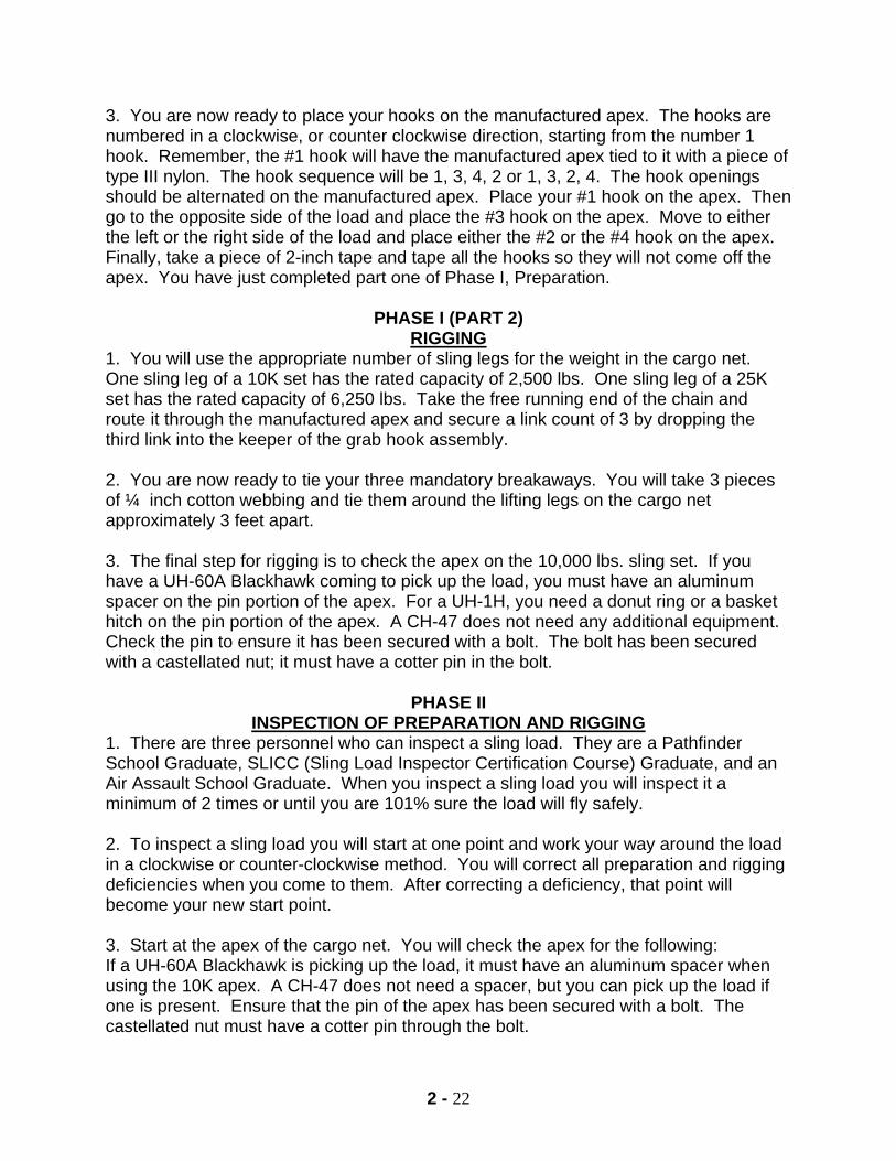
2 - 22
3. You are now ready to place your hooks on the manufactured apex. The hooks are numbered in a clockwise, or counter clockwise direction, starting from the number 1 hook. Remember, the #1 hook will have the manufactured apex tied to it with a piece of type III nylon. The hook sequence will be 1, 3, 4, 2 or 1, 3, 2, 4. The hook openings should be alternated on the manufactured apex. Place your #1 hook on the apex. Then go to the opposite side of the load and place the #3 hook on the apex. Move to either the left or the right side of the load and place either the #2 or the #4 hook on the apex. Finally, take a piece of 2-inch tape and tape all the hooks so they will not come off the apex. You have just completed part one of Phase I, Preparation.
PHASE I (PART 2) RIGGING
1. You will use the appropriate number of sling legs for the weight in the cargo net. One sling leg of a 10K set has the rated capacity of 2,500 lbs. One sling leg of a 25K set has the rated capacity of 6,250 lbs. Take the free running end of the chain and route it through the manufactured apex and secure a link count of 3 by dropping the third link into the keeper of the grab hook assembly. 2. You are now ready to tie your three mandatory breakaways. You will take 3 pieces of ¼ inch cotton webbing and tie them around the lifting legs on the cargo net approximately 3 feet apart. 3. The final step for rigging is to check the apex on the 10,000 lbs. sling set. If you have a UH-60A Blackhawk coming to pick up the load, you must have an aluminum spacer on the pin portion of the apex. For a UH-1H, you need a donut ring or a basket hitch on the pin portion of the apex. A CH-47 does not need any additional equipment. Check the pin to ensure it has been secured with a bolt. The bolt has been secured with a castellated nut; it must have a cotter pin in the bolt.
PHASE II
INSPECTION OF PREPARATION AND RIGGING 1. There are three personnel who can inspect a sling load. They are a Pathfinder School Graduate, SLICC (Sling Load Inspector Certification Course) Graduate, and an Air Assault School Graduate. When you inspect a sling load you will inspect it a minimum of 2 times or until you are 101% sure the load will fly safely. 2. To inspect a sling load you will start at one point and work your way around the load in a clockwise or counter-clockwise method. You will correct all preparation and rigging deficiencies when you come to them. After correcting a deficiency, that point will become your new start point. 3. Start at the apex of the cargo net. You will check the apex for the following: If a UH-60A Blackhawk is picking up the load, it must have an aluminum spacer when using the 10K apex. A CH-47 does not need a spacer, but you can pick up the load if one is present. Ensure that the pin of the apex has been secured with a bolt. The castellated nut must have a cotter pin through the bolt.
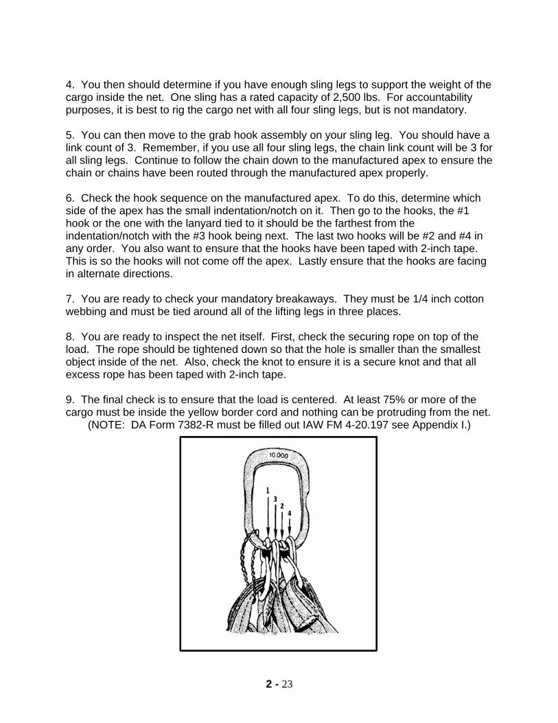
2 - 23
4. You then should determine if you have enough sling legs to support the weight of the cargo inside the net. One sling has a rated capacity of 2,500 lbs. For accountability purposes, it is best to rig the cargo net with all four sling legs, but is not mandatory. 5. You can then move to the grab hook assembly on your sling leg. You should have a link count of 3. Remember, if you use all four sling legs, the chain link count will be 3 for all sling legs. Continue to follow the chain down to the manufactured apex to ensure the chain or chains have been routed through the manufactured apex properly. 6. Check the hook sequence on the manufactured apex. To do this, determine which side of the apex has the small indentation/notch on it. Then go to the hooks, the #1 hook or the one with the lanyard tied to it should be the farthest from the indentation/notch with the #3 hook being next. The last two hooks will be #2 and #4 in any order. You also want to ensure that the hooks have been taped with 2-inch tape. This is so the hooks will not come off the apex. Lastly ensure that the hooks are facing in alternate directions. 7. You are ready to check your mandatory breakaways. They must be 1/4 inch cotton webbing and must be tied around all of the lifting legs in three places. 8. You are ready to inspect the net itself. First, check the securing rope on top of the load. The rope should be tightened down so that the hole is smaller than the smallest object inside of the net. Also, check the knot to ensure it is a secure knot and that all excess rope has been taped with 2-inch tape. 9. The final check is to ensure that the load is centered. At least 75% or more of the cargo must be inside the yellow border cord and nothing can be protruding from the net.
(NOTE: DA Form 7382-R must be filled out IAW FM 4-20.197 see Appendix I.)
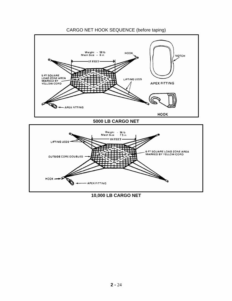
2 - 24
CARGO NET HOOK SEQUENCE (before taping)
5000 LB CARGO NET
10,000 LB CARGO NET

2 - 25
NOTES
2 - 26
A-22 CARGO BAG
SERVICEABILITY AND ACCOUNTABILITY INSPECTION
1. The minimum safe sling load weight for the A-22 bag is 500 lbs. The maximum weight is 2,200 lbs. 2. Prior to preparing or rigging the A-22 bag for a sling load operation, you must inspect all of its component parts for serviceability and accountability. 3. Inspect for holes, rips, or frays in excess of one inch in diameter. If any holes, rips, or frays are present, you must replace or repair that component. 4. Inspect for petroleum base stains, rust, or mildew. If these are present, attempt to remove them with warm soapy water and a stiff brush. 5. Inspect all stitching for loose or broken stitches. Utilize the stitch rule: If 3 consecutive stitches or 5 in one area are loose or broken, you must repair or replace the component. 6. Inspect the lacing loops to ensure that they have not been sewn closed and are present. 7. Inspect the rectangular portion of the canvas cover for a current inspection date. It must be current within 6 months of the inspection date. It will be in 1 inch block letters ( in black or blue parachute rigging ink) indicating the month and year it was inspected. 8. You will then inspect the scuff pad assembly. 9. Inspect for holes, rips, or frays in excess of 1 inch in diameter. 10. Check for petroleum base stains, rust, or mildew. 11. Inspect all stitching using the stitch rule. 12. Inspect the vertical and lateral straps for cuts, frays, and stains. 13. Inspect the metal portions of the A-22 bag for rust, cracks, dents, nicks, or burns. 14. Inspect the two 188 inch straps for cuts, frays, or stains. 15. Inspect the suspension webbing straps. There should be 4. Each strap has a rated capacity of 2,200 lbs. There are two types of straps. They are cotton and nylon. You will never mix the two types of straps. You can identify a cotton strap by its off white color and the red stitching. The nylon strap is OD green in color and is half the thickness of a cotton strap.
2 - 27
16. Inspect the straps for frays, cuts, or stains. 17. Check for loose or broken stitches using the stitch rule. 18. Inspect all metal portions for rust, cracks, dents, nicks, or burns. 20. Ensure butterfly hooks are spring loaded and move freely. 21. There are three types of lacing ropes that can be used with the A-22 bag. They are 3/8 inch hemp rope, 7/16 inch nylon rope, and type III nylon. A total of four ropes are needed. 22. The rated capacity 3/8 inch hemp rope is 3,180 lbs. The rated capacity for 7/8 inch nylon rope is 4,500 lbs. Type III nylon has a rated capacity of 550 lbs. 23. Inspect the free running ends of your ropes to ensure that they are not excessively frayed, and have been secured with 2 inch tape or have been whipped and dipped. 25. Inspect each strand of rope to ensure it is not cut or frayed more than half the diameter of an individual strand. 26. Check the medium clevis (FIG 2-22) for rust, cracks, nicks, dents, and burrs. Also, ensure the clevis has the bolt and nut and that they are not stripped out.
PHASE I (PART 1) PREPARATION
1. Place the scuff pad on the ground with the over sewn portion facing down. 2. Place the canvas cover on top of the scuff pad assembly. Match up the rectangular portions. 3. Pull the canvas cover on top of the scuff pad assembly. Match up the rectangular portions. 4. Place the load on the rectangular portion of the canvas cover so that it is centered.
PHASE I (PART 2) RIGGING
1. Fold the canvas cover the top of the load. Fold any excess cover material under the top flaps.
2. Secure the corners with the lacing types. To do this, you will route your lacing rope from ground skyward through the bottom two loops. Then form an X with the lacing rope and route the free running ends through the top two lacing loops from ground
2 - 28
skyward. You will then secure the rope with a bow knot and tape the excess rope with 2 inch tape. 3. Secure the 188 inch straps across the load so that they form a cross. Then locate the friction adapter buckle opposite of each strap. Route the 188 inch strap through the friction adapter and then tighten down. Do not incorporate any twists. Secure the excess strap with 2 inch tape or 1/4 inch cotton webbing. 4. Route the lateral straps to their friction adapters. To tighten, start from the bottom and move to the top. Tighten down opposite corners at the same time. You will then roll and tape all excess straps; Do not incorporate any twists. 5. Place your suspension webbing straps onto your suspension webbing D-rings. To do this, hook your butterfly fasteners onto the D-rings with the hooks facing down toward the load and tape the hooks with 2 inch tape. 6. Attach the D-rings of all four suspension webs, to the bolt of the med. clevis, in a clock wise or counter clock wise sequence. Ensure that the straps are not twisted more than a half twist. 7. Secure the bolt with the nut and tape both ends of the bolt with 2 inch tape.
8. Route the free running end of the chain from the sling leg through the medium clevis and place a chain link count of 3 into the keeper portion of the grab hook assembly for a 10k sling set or link 5 for 25k.
9. Rig the apex of the sling leg for the type of aircraft that will be picking up the load. A UH-60 Blackhawk must have an aluminum spacer on it, and a UH-1H must have an apex ring or a basket hitch. A CH-47 does not require any additional items on the apex. Check the nut on the apex. The castellated nut must have a cotter pin in it.
PHASE II
INSPECTION OF PREPARATION AND RIGGING
1. Start your inspection at the apex. Check to ensure the bolt is present and secured with a nut. The castellated nut must have a cotter pin in it. Inspect to ensure that the apex is setup for the appropriate inbound aircraft. A UH-60 aluminum spacer, UH-1H basket hitch or donut ring, CH-47 does not require additional items on the apex. 2. Check the link count to ensure you have a link count of 3. 3. Check the medium clevis to ensure it has tape on both ends of the bolt and that the D-rings are on the bolt and in the proper sequence. 4. Check to ensure your suspension webbing straps are all of the same type (either all cotton or all nylon). Check the butterfly snap hooks to ensure that they are all facing down toward the load and taped with 2 inch tape.
2 - 29
5. Check the 188 inch straps to ensure they form a cross on top of the load. Ensure they are routed under the lateral straps. Also, check to ensure they have been tightened down, free of twists and do not have quick releases. Ensure that all of the excess strap has been taped with 2 inch tape. 6. You will move to one corner and start at the top. Check the lateral strap for proper routing, it is free of twists, and verify that it has been tightened down and excess strap has been taped with 2 inch tape. Check the middle and bottom strap for the same things. Remember, if one strap has a quick release, all lateral straps must have a quick release. 7. Check the lacing rope to ensure it has been properly routed through the lacing loops from ground to the sky. Check that the rope forms an X and is routed properly through the top lacing loops. Finally, check the rope to ensure it has been secured with a bow knot, and that the excess rope has been secured with 2 inch tape. 8. Inspect the other three corners in the same manner. (NOTE: DA Form 7382-R must be filled out IAW FM 4-20.197 see Appendix I.)
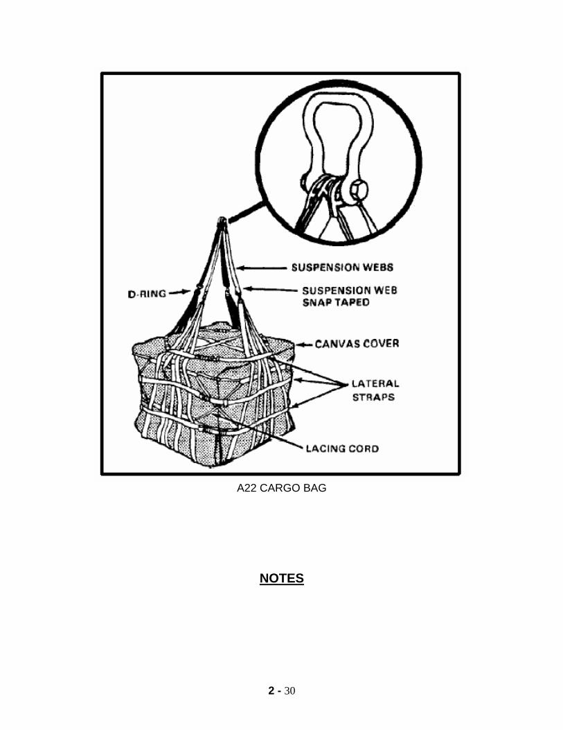
2 - 30
A22 CARGO BAG
NOTES
2 - 31
M998/M1038 TRUCK, CARGO, 1 1/4-TON (HMMWV) a. Applicability. Certified by US Army NATICK for CH-47 helicopter at airspeeds up to and including 90 knots. Both trucks are also certified by NATICK for the UH-60 helicopter with the following limitations: 1. With a vehicle gross rigged weight of less than 7,300 lbs., the UH-60 is restricted to airspeeds up to and including 100 knots. 2. With a vehicle gross rigged weight between 7,300 lbs. and 7,700 lbs., the UH-60 is limited to 70 knots. NOTE: When using UH-60 support, coordinate closely with the aviation unit in reference to the vehicle weight. b. Load Description. 1. M998 truck, 1 1/4 ton (HMMWV) 2. M1038 truck, 1 1/4 ton (HMMWV) 3. Weight a. Empty, 5,200 lbs. b. ACL, 2,500 lbs. c. Loaded, 7,700 lbs.
WARNING
VEHICLE GROSS RIGGED WEIGHT IS RESTRICTED TO 7,700 LBS.
d. Materials. 1. Sling set (10,000 lbs. capacity) (UH-60 or CH-47). 2. Tape, adhesive, pressure-sensitive, 2-inch wide roll. 3. Cord, nylon, Type III, 550 lbs. breaking strength. 4. Webbing, cotton, 1/4 inch, 80-pound breaking strength. e. Personnel. Two people can prepare and rig the load in 15 minutes.

2 - 32
PHASE I (PART 1)
PREPARATION 1. Begin preparing the load at any point and continue around in a 360-degree motion until you return to your start point either clockwise or counterclockwise. Start at the passenger side windshield. 2. The windshield will be taped and padded IAW your unit SOP. At minimum make an X configuration with two-inch tape both inside and outside. Rotate the mirrors forward towards the windshield and secure them with type III nylon. Inspect your front lift points for any rust, dents, cracks, nicks, and burrs. 3. The hood will be secured with latches provided and two-inch tape. Wheels will be in the straightforward position. All glass and plastic, i.e. turn signals and headlights will be taped IAW your unit SOP. Again, the other side of the hood will be latched and taped with two-inch tape. You now come to the other rearview mirror. It also is rotated forward and secured with type III nylon and the windshield is shatterproof with two-inch tape in an X configuration both inside and outside. The ends of the vehicle bumper guides will be padded with two-inch tape or antenna balls. 4. Now, when preparing the interior of the vehicle, work your way from the inside towards the outside. 5. Start with the transmission and make sure it is in neutral. Check the hand brake and make sure it is in the engaged position. The steering wheel will be secured with type III nylon to a fixed portion of the load in at least two places. Also, make sure that electrical switches and the engine ignition switch are in the off position, and check for a proper fuel level of 75 % or less. The last thing to prepare on the inside is the seat belts. The male portion must be rolled, taped and tucked behind the seat and the female portion will be rotated up behind the data plate and taped in place with two-inch tape. If the vehicle has the three-point lap belt, it will be secured as worn. All canvas doors and other cargo will be secured in the rear of the vehicle. 6. Move towards the rear. The troop seats will be up and secured with the pins provided. If one of the pins is missing, the troop seat will be secured with type III nylon in two places. All glass and plastic will be taped and padded IAW your unit SOP. Rotate the tailgate to the up position, secure it with the hooks and chains provided and secure the hooks with type III nylon. The sling guides will be padded IAW your unit SOP. 7. Inspect your rear lift points for any rust, dents, cracks, nicks, or burrs. If any are present, take the appropriate action. Ensure the towing pintle is closed and secured with a cotter pin, two-inch tape, or type III nylon. The electrical connector needs to be spring loaded and have a rubber gasket in it. If no gasket is found, tape it closed with two-inch tape.
2 - 33
8. Move around the other side of the vehicle and the first thing you should come to is the fuel cap. You will roll, tape and tuck the male portion of the seat belt behind the seat and rotate the female portion up behind the seat and the data plate and tape it with two-inch tape. If the vehicle has the three-point lap belt, it will be secured as worn. 9. The last thing you will prepare is the battery and battery box. The battery will be free from all corrosion and have a good connection. Once the batteries have been checked, close the battery box, latch it and tape the latches with two-inch tape.
PHASE I (PART 2)
RIGGING 1. Place one 10K sling set on the load with the inner two sling legs routed to the rear of the vehicle and the outer two sling legs routed to the front of the vehicle (FIG 2-19), over the roll bar, over the windshield and routed to the two lift points. The apex must be secured with the bolt, castellated nut, and cotter pin provided. 2. Move to the front right lift point. The link count to the front is eighty. Grab the free running end of the chain and route it through the lift point, inside out or outside in (it does not matter). Secure a link count of eighty by dropping the 80th link in the keeper portion of the grabhook assembly. Secure all excess links by wrapping the excess around the lifting chains and securing it with type III nylon. Repeat this process on the left front lift point. 3. Move to the rear of the vehicle. Begin with the left rear lift point. Grab the free running end of the chain and route it down through the sling guide, through the lift point and back up through the sling guide (FIG 2-20). Secure a link count of three by dropping the 3rd link into the keeper portion of the grab hook assembly. Repeat this process on the left front lift point. 4. Next you will tie the appropriate breakaways. All breakaways are tied with one turn of 1/4" cotton webbing. Before tying the first breakaway, pull all slack toward the rear of
the vehicle. The first mandatory breakaway is tied around the roll bar and the front two sling legs centered on the roll bar and tied in a secured knot. If your vehicle is equipped with troop seats, you must
tie additional breakaways. Lay the grabhook assembly across the troop seat next to the troop strap retainer ring. Route a piece of 1/4" cotton webbing through the troop strap retainer ring and through both lifting chains and tied in a secured knot. Repeat this process on the opposite side. If the vehicle is not equipped with troop seats you will tie a tight "T." To tie a tight "T," pull all slack upwards on both rear
sling legs and pull both grabhook assemblies together. Then tie a breakaway in one of four authorized positions. These are around the sling legs, through the potted eye, through the eye portion of the
grabhook assembly or routed through all four lifting chains.
2 - 34
PHASE II
INSPECTION OF PREPARATION AND RIGGING 1. The only personnel qualified to inspect this load are a Pathfinder School Graduate, SLICC (Sling Load Inspector Certification Course) Graduate, or an Air Assault School Graduate. You will inspect this load at least twice or until you are 101% sure that it will fly safely. Your inspection will start on the passenger side of the vehicle. 2. First, inspect the windshield and make sure it is properly shatter-proofed. Then, check the mirrors and make sure they are rotated forward and secured with type III nylon. Check the hood latches to make sure they are secured and taped with two inch tape and that the wheel is straight. 3. Move around to the front and inspect for a link count of 80 and that the excess links are secured with type III nylon. Then check all the glass and plastic in the front and make sure it is taped and padded IAW unit SOP. Moving to the other side you once again check to see that the wheels are straight, the hood is latched and taped with two-inch tape, the mirrors are rotated forward and secured with type III nylon and that the windshield is shatterproof with two-inch tape in an X configuration both inside and out. 4. On the inside of the vehicle check the transmission and make sure that it is in neutral and the parking brake is engaged. Then check all the electrical switches and the engine ignition switch to make sure they are off, and the fuel level is 75 % or less. Check to ensure the steering wheel is secured with type III nylon to a fixed portion of the load and then check the seat belts. Make sure the male portion is rolled, taped and tucked, and that the female portion is rotated up behind the data plate and taped with two-inch tape. If the vehicle has the three-point lap belt, it will be secured as worn. 5. Move to the rear of the load and inspect the troop seats to ensure that they are secured in the up position with the pins provided, or secured in two places with type III nylon. At the rear of the vehicle you will inspect a vehicle with troop seats in a U shaped sequence. Begin by inspecting for a link count of three. Move to the breakaway and inspect for 1/4" cotton webbing. Move down to ensure the chains are routed through the sling guides. Ensure the tailgate is secured with the hooks and chains and that the hooks are secured with type III nylon. Inspect glass and plastic for tape and padding IAW unit SOP. Ensure chains are routed through the lift point. Inspect the towing pintle to ensure that it is secured closed with the cotter pin or two inch tape or type III nylon. Check the electrical connector for a rubber gasket and ensure it is spring loaded. Moving to the front, ensure the chains are routed through the lift point. Inspect glass and plastic for tape and padding. Ensure the tailgate is secured
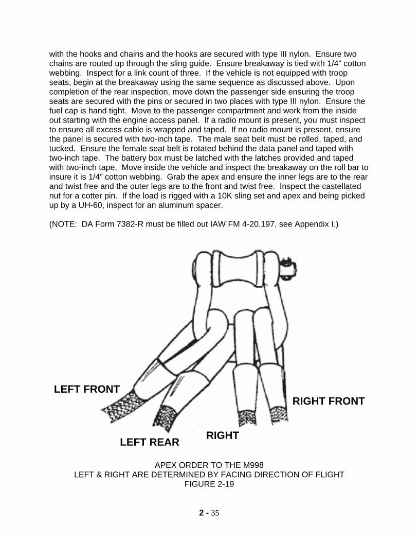
2 - 35
with the hooks and chains and the hooks are secured with type III nylon. Ensure two chains are routed up through the sling guide. Ensure breakaway is tied with 1/4” cotton webbing. Inspect for a link count of three. If the vehicle is not equipped with troop seats, begin at the breakaway using the same sequence as discussed above. Upon completion of the rear inspection, move down the passenger side ensuring the troop seats are secured with the pins or secured in two places with type III nylon. Ensure the fuel cap is hand tight. Move to the passenger compartment and work from the inside out starting with the engine access panel. If a radio mount is present, you must inspect to ensure all excess cable is wrapped and taped. If no radio mount is present, ensure the panel is secured with two-inch tape. The male seat belt must be rolled, taped, and tucked. Ensure the female seat belt is rotated behind the data panel and taped with two-inch tape. The battery box must be latched with the latches provided and taped with two-inch tape. Move inside the vehicle and inspect the breakaway on the roll bar to insure it is 1/4” cotton webbing. Grab the apex and ensure the inner legs are to the rear and twist free and the outer legs are to the front and twist free. Inspect the castellated nut for a cotter pin. If the load is rigged with a 10K sling set and apex and being picked up by a UH-60, inspect for an aluminum spacer. (NOTE: DA Form 7382-R must be filled out IAW FM 4-20.197, see Appendix I.)
APEX ORDER TO THE M998 LEFT & RIGHT ARE DETERMINED BY FACING DIRECTION OF FLIGHT
FIGURE 2-19
RIGHT FRONT
LEFT REAR RIGHT
LEFT FRONT
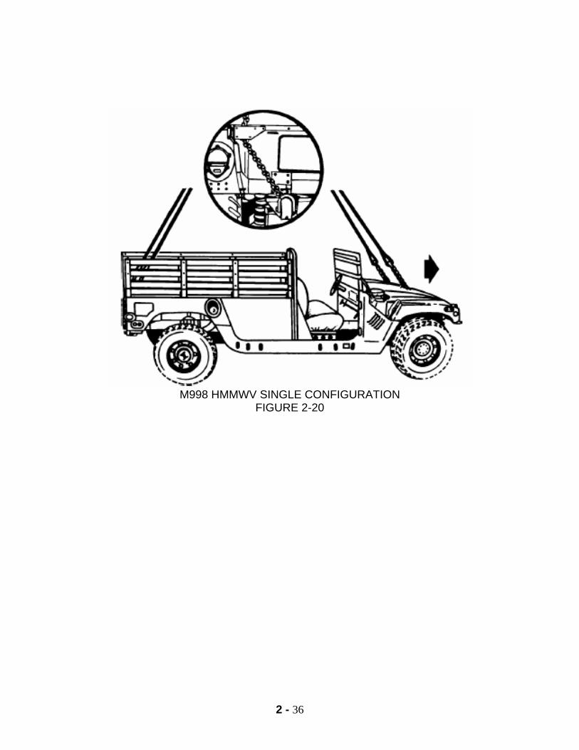
2 - 36
M998 HMMWV SINGLE CONFIGURATION
FIGURE 2-20

2 - 37
NOTES
2 - 38
ONE TO FOUR 500 GALLON FUEL DRUMS
1. APPLICABILITY. One fuel drum is certified by the U. S. Army NATICK for UH-60 and CH-53A/D/E helicopters at airspeeds up to and including 80 and 120 knots, respectively. One to four fuel drums is a suitable load for the CH-47 helicopter at airspeeds up to and including 80 knots. 2. LOAD DESCRIPTION. Drum, fabric, fuel, 500 gallons capacity. 3. WEIGHT. a. Drum- empty, 250 lbs. b. One drum, maximum weight 4,200 lbs. c. Two drums maximum weight 8,400 lbs. d. Three drums maximum weight 12,600 lbs. e. Four drums maximum weight 16,800 lbs. NOTE: Exact weight of each drum may vary depending on type and amount of fuel. 4. MATERIALS. a. Sling sets. 1. One drum, (2) 10,000 or (2) 25,000 lbs. capacity slinglegs. 2. Two drums, (4) 10,000 or (4) 25,000 lbs. capacity slinglegs. 3. Three drums, (4) 25,000 lbs. capacity slinglegs. 4. Four drums, (4) 25,000 lbs. capacity slinglegs. b. Tape, adhesive, pressure-sensitive, 2 inch wide roll. c. Webbing, cotton, 1/4 inch, 80 lbs. breaking strength.
b. Cord, nylon, Type III, 550 lbs. breaking strength. 5. PERSONNEL. Two people can rig one to four drums in 5 to 15 minutes.
2 - 39
SERVICEABILITY AND ACCOUNTABILITY INSPECTION
1. When preparing the fuel blivets, you must conduct a serviceability inspection. The three sections you will inspect are as follows, a. Front circular portion. b. Rear circular portion. c. Black rubber portion. 2. When inspecting the front circular portion, you will look for the following: a. Fuel nozzle. 1. Foreign materials (if any, remove it). 2. Ensure black rubber gasket inside is present. b. Fuel cap. 1. If the fuel cap is not present, cover fuel opening with 2 inch tape. 2. When the locking levers are folded to the sides, the cap is in the locked position. When the locking levers are extended, the cap is in the unlocked position. 3. Inspect the inside of the cap. The black rubber gasket must be present. c. Lift points. 1. Lift points are 5/8 inch screw pin clevis, which has a rated capacity of 4,420 lbs. 2. Inspect threads of screw pin clevis to ensure they are not stripped and the cotter pin is present. 3. Inspect for rust, cracks, nicks, dents, and burrs, then take the appropriate action. d. Bezel ring. 1. Ensure the bezel ring rotates freely 360 degrees in both directions; because the fuel blivets tend to rotate while in-flight.
2 - 40
2. Check all hex head bolts to ensure none of them are protruding from the bezel ring or large circular portion. 3. When inspecting the rear circular portion, it is the same as the front, except there may or may not be a fuel nozzle. 4. When inspecting the black rubber portion, look for the following: Cuts, cracks, gouges, or areas worn to the white threading. Anything that is leaking or could become a leak, will deem the fuel blivets unserviceable.
PHASE I
PREPARATION AND RIGGING 1. Install all fuel caps and ensure they are secured in the locked position with type III nylon. 2. If no dust cover is present, cover the fuel opening with 2 inch tape. 3. Ensure screw pin clevises have cotter pins. 4. Rigging of the 500 gallon fuel blivets with 25,000 lbs. sling set. a. One fuel blivet. 1. 2 sling legs with 1 apex 2. Lift points rotated to the 12 o'clock position 3. Link count 3 at each lift point 4. Tie one mandatory breakaway with ¼" cotton webbing
b. Two fuel blivets. 1. Four sling legs and apex. 2. Apex order as follows: a. The center legs to the lightest fuel blivet. b. The outer legs to the heaviest fuel blivet. c. Link count of three at each lift point.
2 - 41
NOTE: If you have a 10,000 lbs. sling set available, you may sling load them exactly the same way you sling load 1 and 2 fuel blivets with a 25,000 lbs. sling set. However, 2 fuel blivets are the maximum you can lift on a 10,000 lbs. sling set with 4 legs. c. Two fuel blivets (pilot preferred method). 1. Two fuel blivets rigged as a dual load on two sling legs. 2. Rotate lift points to the 3 o’clock - 9 o’clock position. 3. Route the free running end of the chain through the two inside lift points. NOTE: When routing the chain lift points, go same direction on both...(i.e. left to right through lift point at the 9 o’clock position). 4. Secure a link count of three. 5. Ensure you have no chain to chain contact on both lift points. 6. Apex order is as follows: a. The left sling leg to the left side of the blivets. b. The right sling leg to the right side of the blivets. 7. There is one mandatory breakaway in the center of the blivets. D. Three fuel blivets. a. Configuration. Two blivets in the dual hookup mode (pilot preferred), and one blivet in the single hookup mode. b. Utilize four sling legs and apex to the 25,000 lbs. sling set only. c. Apex order is as follows: 1. The inside sling legs to the single fuel blivet. 2. The outside sling legs to the pilot preferred blivets. d. There are two mandatory breakaways. One breakaway around one set of dual hookups and one between the single hookup. E. Four fuel blivets. a. Configuration. Rig two pair of pilot preferred methods.
2 - 42
b. Utilize four sling legs and apex to the 25,000 lbs. sling set only. c. Apex order is as follows: 1. The inside sling legs are routed to the lightest pilot preferred blivets 2. The outside sling legs are routed to the heaviest pilot preferred blivets d. There are two mandatory breakaways. One between each pilot preferred method. PHASE II
INSPECTION OF PREPARATION AND RIGGING
1. There are only three personnel qualified to inspect this load. They are as follows: a. Pathfinder School Graduate. b. Air Assault School graduate.
c. SLICC (Sling Load Inspector Certification Course) Graduate.
2. When you inspect this load, you will start at one end of the load, and work in a 360 degree manner and from top to bottom. If you find deficiency, you will stop and correct that deficiency, and restart your inspection process from there. Inspect a minimum of two times or until you are 101% sure the load will fly safely. 3. The inspection sequence is as follows: a. Apex has a castellated nut with cotter pin. b. Apex order is as follows: 1. One blivet. a. The left sling leg to the left side. b. The right sling legs to the right side. 2. Two blivets (Four legs). a. The inside sling legs to the lightest blivet. b. The outside sling legs to the heaviest blivet. 3. Three blivets.
2 - 43
a. The inside sling legs to the single blivet. b. The outside sling legs to the dual blivets. 4. Four blivets. a. The inside sling legs to lightest set of blivets. b. The outside sling legs to heaviest other blivets. c. Sling legs. Ensure they are not crossed, misrouted through, or under the triangle on the dual blivets, or out of order. d. Breakaways. Ensure they are made of 1/4 inch cotton webbing. Ensure that there is one breakaway for every two sling legs, tied on top and is in the center of the fuel blivets or between the dual blivets. e. Sling leg chains. 1. Ensure a link count of 3 (or 55 for a single blivet in a three blivet configuration). 2. Ensure the chain passes through one lift point and is not misrouted around the fuel cap/nozzle. 3. Ensure that the excess link count of 10 or more will be secured with type III nylon. 4. Ensure there is no chain to chain contact present on the pilot preferred blivets. f. Lift points. 1. Ensure they are routed to the 12 o’clock position for the single blivet, or 3 to 9 o’clock position for dual blivets. 2. Ensure the cotter pin is in the 5/8 inch screw pin clevis. g. Fuel nozzle. 1. Ensure the cap is in place and secured properly with type III nylon on the locking arms or with 2 inch tape over the fuel nozzle.
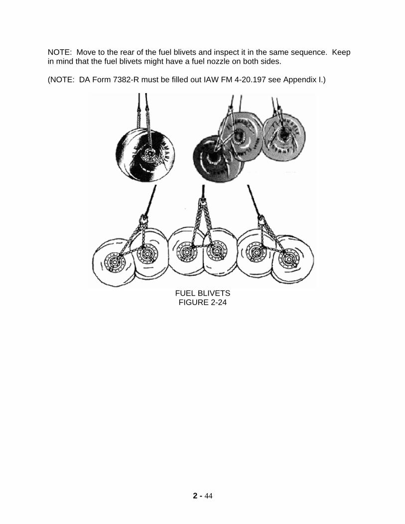
2 - 44
NOTE: Move to the rear of the fuel blivets and inspect it in the same sequence. Keep in mind that the fuel blivets might have a fuel nozzle on both sides. (NOTE: DA Form 7382-R must be filled out IAW FM 4-20.197 see Appendix I.)
FUEL BLIVETS FIGURE 2-24

2 - 45
NOTES
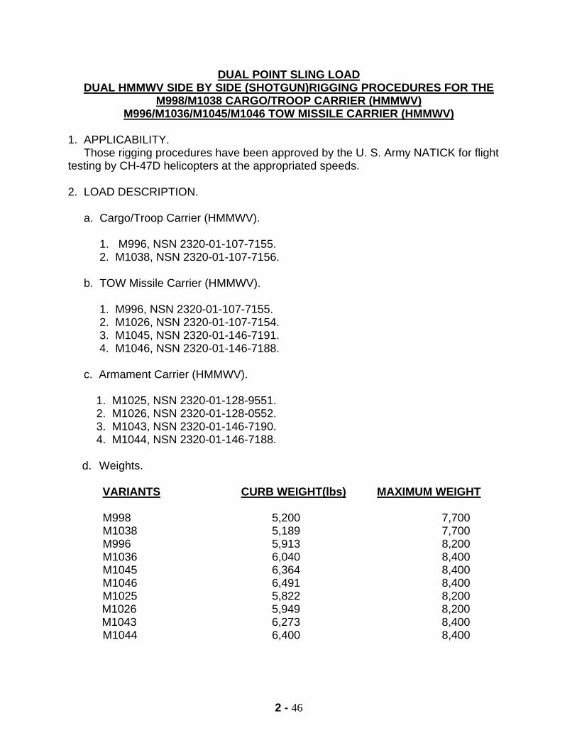
2 - 46
DUAL POINT SLING LOAD DUAL HMMWV SIDE BY SIDE (SHOTGUN)RIGGING PROCEDURES FOR THE
M998/M1038 CARGO/TROOP CARRIER (HMMWV) M996/M1036/M1045/M1046 TOW MISSILE CARRIER (HMMWV)
1. APPLICABILITY. Those rigging procedures have been approved by the U. S. Army NATICK for flight testing by CH-47D helicopters at the appropriated speeds. 2. LOAD DESCRIPTION. a. Cargo/Troop Carrier (HMMWV). 1. M996, NSN 2320-01-107-7155. 2. M1038, NSN 2320-01-107-7156. b. TOW Missile Carrier (HMMWV). 1. M996, NSN 2320-01-107-7155. 2. M1026, NSN 2320-01-107-7154. 3. M1045, NSN 2320-01-146-7191. 4. M1046, NSN 2320-01-146-7188. c. Armament Carrier (HMMWV). 1. M1025, NSN 2320-01-128-9551. 2. M1026, NSN 2320-01-128-0552. 3. M1043, NSN 2320-01-146-7190. 4. M1044, NSN 2320-01-146-7188.
d. Weights.
VARIANTS CURB WEIGHT(lbs) MAXIMUM WEIGHT M998 5,200 7,700 M1038 5,189 7,700 M996 5,913 8,200 M1036 6,040 8,400 M1045 6,364 8,400 M1046 6,491 8,400 M1025 5,822 8,200 M1026 5,949 8,200 M1043 6,273 8,400 M1044 6,400 8,400
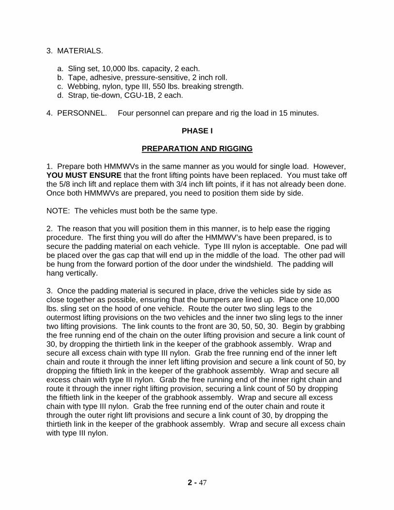
2 - 47
3. MATERIALS. a. Sling set, 10,000 lbs. capacity, 2 each. b. Tape, adhesive, pressure-sensitive, 2 inch roll. c. Webbing, nylon, type III, 550 lbs. breaking strength. d. Strap, tie-down, CGU-1B, 2 each. 4. PERSONNEL. Four personnel can prepare and rig the load in 15 minutes.
PHASE I
PREPARATION AND RIGGING
1. Prepare both HMMWVs in the same manner as you would for single load. However, YOU MUST ENSURE that the front lifting points have been replaced. You must take off the 5/8 inch lift and replace them with 3/4 inch lift points, if it has not already been done. Once both HMMWVs are prepared, you need to position them side by side. NOTE: The vehicles must both be the same type. 2. The reason that you will position them in this manner, is to help ease the rigging procedure. The first thing you will do after the HMMWV’s have been prepared, is to secure the padding material on each vehicle. Type III nylon is acceptable. One pad will be placed over the gas cap that will end up in the middle of the load. The other pad will be hung from the forward portion of the door under the windshield. The padding will hang vertically. 3. Once the padding material is secured in place, drive the vehicles side by side as close together as possible, ensuring that the bumpers are lined up. Place one 10,000 lbs. sling set on the hood of one vehicle. Route the outer two sling legs to the outermost lifting provisions on the two vehicles and the inner two sling legs to the inner two lifting provisions. The link counts to the front are 30, 50, 50, 30. Begin by grabbing the free running end of the chain on the outer lifting provision and secure a link count of 30, by dropping the thirtieth link in the keeper of the grabhook assembly. Wrap and secure all excess chain with type III nylon. Grab the free running end of the inner left chain and route it through the inner left lifting provision and secure a link count of 50, by dropping the fiftieth link in the keeper of the grabhook assembly. Wrap and secure all excess chain with type III nylon. Grab the free running end of the inner right chain and route it through the inner right lifting provision, securing a link count of 50 by dropping the fiftieth link in the keeper of the grabhook assembly. Wrap and secure all excess chain with type III nylon. Grab the free running end of the outer chain and route it through the outer right lift provisions and secure a link count of 30, by dropping the thirtieth link in the keeper of the grabhook assembly. Wrap and secure all excess chain with type III nylon.
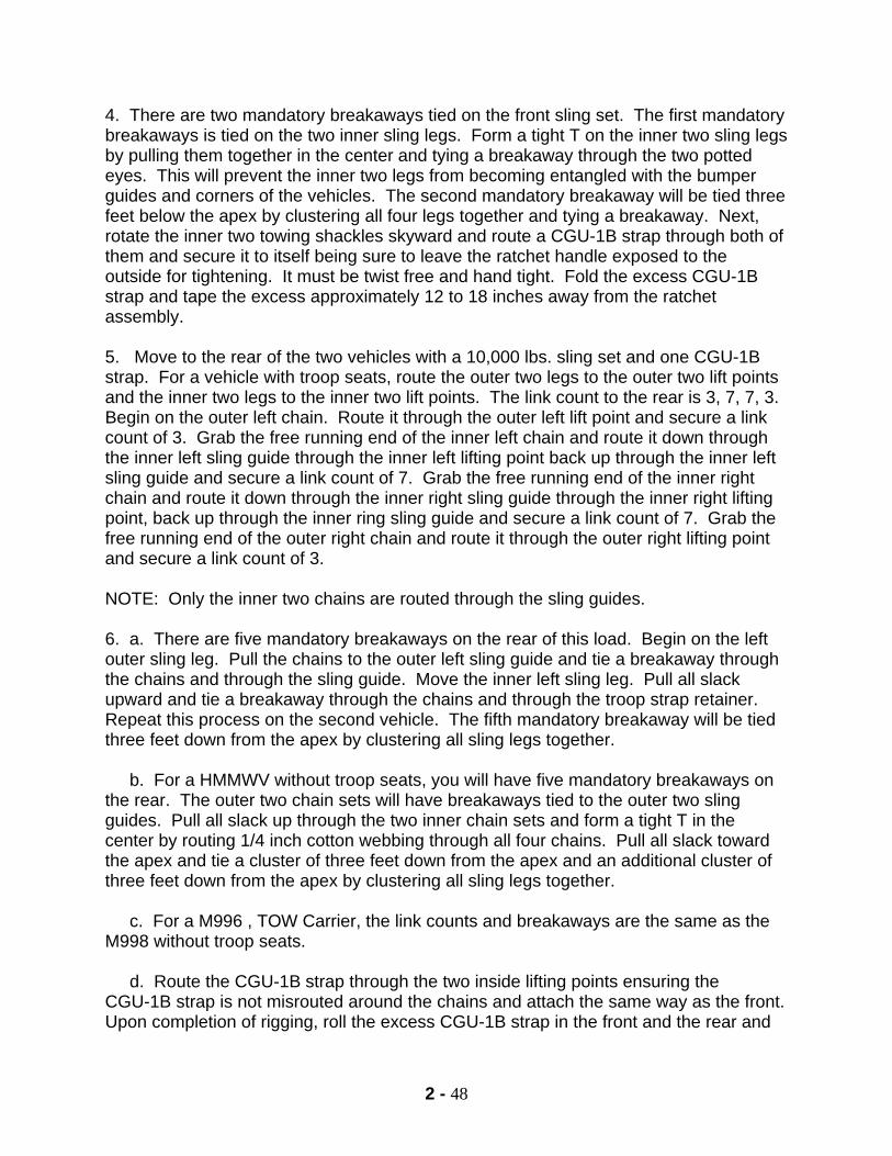
2 - 48
4. There are two mandatory breakaways tied on the front sling set. The first mandatory breakaways is tied on the two inner sling legs. Form a tight T on the inner two sling legs by pulling them together in the center and tying a breakaway through the two potted eyes. This will prevent the inner two legs from becoming entangled with the bumper guides and corners of the vehicles. The second mandatory breakaway will be tied three feet below the apex by clustering all four legs together and tying a breakaway. Next, rotate the inner two towing shackles skyward and route a CGU-1B strap through both of them and secure it to itself being sure to leave the ratchet handle exposed to the outside for tightening. It must be twist free and hand tight. Fold the excess CGU-1B strap and tape the excess approximately 12 to 18 inches away from the ratchet assembly. 5. Move to the rear of the two vehicles with a 10,000 lbs. sling set and one CGU-1B strap. For a vehicle with troop seats, route the outer two legs to the outer two lift points and the inner two legs to the inner two lift points. The link count to the rear is 3, 7, 7, 3. Begin on the outer left chain. Route it through the outer left lift point and secure a link count of 3. Grab the free running end of the inner left chain and route it down through the inner left sling guide through the inner left lifting point back up through the inner left sling guide and secure a link count of 7. Grab the free running end of the inner right chain and route it down through the inner right sling guide through the inner right lifting point, back up through the inner ring sling guide and secure a link count of 7. Grab the free running end of the outer right chain and route it through the outer right lifting point and secure a link count of 3. NOTE: Only the inner two chains are routed through the sling guides. 6. a. There are five mandatory breakaways on the rear of this load. Begin on the left outer sling leg. Pull the chains to the outer left sling guide and tie a breakaway through the chains and through the sling guide. Move the inner left sling leg. Pull all slack upward and tie a breakaway through the chains and through the troop strap retainer. Repeat this process on the second vehicle. The fifth mandatory breakaway will be tied three feet down from the apex by clustering all sling legs together. b. For a HMMWV without troop seats, you will have five mandatory breakaways on the rear. The outer two chain sets will have breakaways tied to the outer two sling guides. Pull all slack up through the two inner chain sets and form a tight T in the center by routing 1/4 inch cotton webbing through all four chains. Pull all slack toward the apex and tie a cluster of three feet down from the apex and an additional cluster of three feet down from the apex by clustering all sling legs together. c. For a M996 , TOW Carrier, the link counts and breakaways are the same as the M998 without troop seats. d. Route the CGU-1B strap through the two inside lifting points ensuring the CGU-1B strap is not misrouted around the chains and attach the same way as the front. Upon completion of rigging, roll the excess CGU-1B strap in the front and the rear and
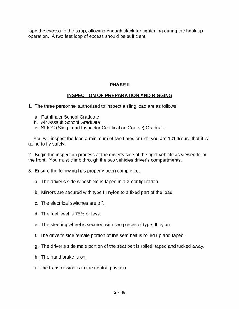
2 - 49
tape the excess to the strap, allowing enough slack for tightening during the hook up operation. A two feet loop of excess should be sufficient.
PHASE II
INSPECTION OF PREPARATION AND RIGGING
1. The three personnel authorized to inspect a sling load are as follows: a. Pathfinder School Graduate
b. Air Assault School Graduate c. SLICC (Sling Load Inspector Certification Course) Graduate You will inspect the load a minimum of two times or until you are 101% sure that it is going to fly safely. 2. Begin the inspection process at the driver’s side of the right vehicle as viewed from the front. You must climb through the two vehicles driver’s compartments. 3. Ensure the following has properly been completed: a. The driver’s side windshield is taped in a X configuration. b. Mirrors are secured with type III nylon to a fixed part of the load. c. The electrical switches are off. d. The fuel level is 75% or less. e. The steering wheel is secured with two pieces of type III nylon. f. The driver’s side female portion of the seat belt is rolled up and taped. g. The driver’s side male portion of the seat belt is rolled, taped and tucked away. h. The hand brake is on. i. The transmission is in the neutral position.
2 - 50
j. The engine access panel is secured with the latches and taped with two inch tape. k. If radio mounts are present, all excess cable is secured. l. The passenger’s side windshield is taped in a X configuration. m. Mirrors are secured with type III nylon to a fixed portion of the load. n. The passenger’s side female portion of the seat belt is routed up and taped. o. The passenger’s side male portion of the seat belt is rolled, taped, and tucked away. p. The battery box is latched and taped. NOTE: Continue the same sequence through the second vehicle. 4. Upon completing the inspection process of the interior of the vehicles, begin the exterior process sequence from the passenger’s side mirror. Ensure the following has been properly completed: The hood is latched and taped with two inch tape. The wheels are straight in the forward position. The bumper guides are removed or padded. The outer link count is 30, and the excess is secured. The inner link count is fifty, and the excess is secured. The breakaways are tied on the inner two sling legs. The cluster breakaways are tied three feet below the apex. The apex order is correct. The castellated nut has the cotter pin in place. The CGU-1B is twist free and hand tight, the excess is secured, and the ratchet is exposed. The glass and plastic is taped and padded IAW your unit’s SOP. The inner link count is 50, and the excess is secured. The outer link count is 30, and the excess is secured. Move towards the rear of the vehicles. The troop seats are secured with the cotter pins, or secured in two places with type III nylon. Start the inspection process at the right rear on the outside. The grab hook assembly is present. The link count is 3, and excess is secured. The breakaways are tied to the sling guides. The chains are not routed through the sling guides. The tailgate is secured with the chains and hooks. The hooks are secured with type III nylon. The chains are routed through the lifting point. The towing pintle is secured with the cotter pin, two inch tape, or type III nylon. The electrical connector is spring loaded with the rubber gasket. The chains are routed through the lift point. The tailgate is secured with chains and hooks. The hooks are secure with type III nylon. The chains are routed through the sling guides. The breakaways are tied to the troop strap retainer ring. The link count is 7, and the excess is secured. The cluster breakaway is three feet below the apex. The castellated nut has the cotter pin in place. The CGU-1B is twist free and hand tight, the excess is secured, and the ratchet is exposed. The inner troop seats are secured with cotter pins or secured in two places with type III nylon. NOTE: Inspect the second vehicle using the same sequence.
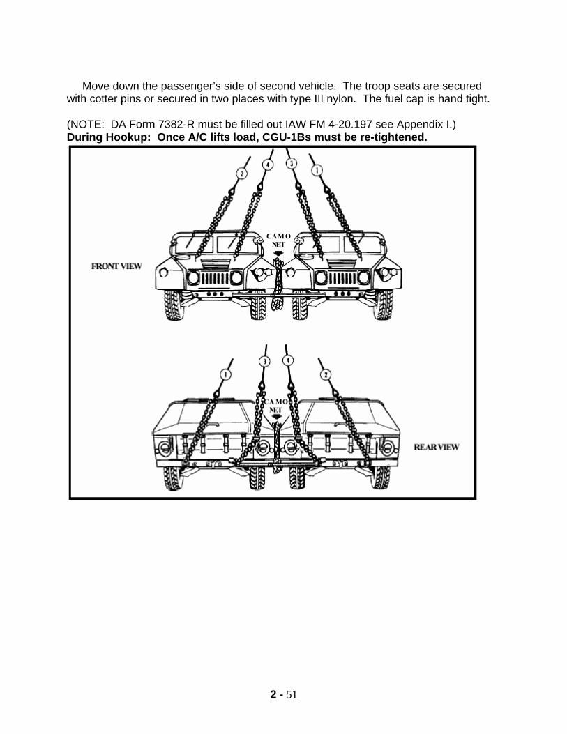
2 - 51
Move down the passenger’s side of second vehicle. The troop seats are secured with cotter pins or secured in two places with type III nylon. The fuel cap is hand tight. (NOTE: DA Form 7382-R must be filled out IAW FM 4-20.197 see Appendix I.) During Hookup: Once A/C lifts load, CGU-1Bs must be re-tightened.
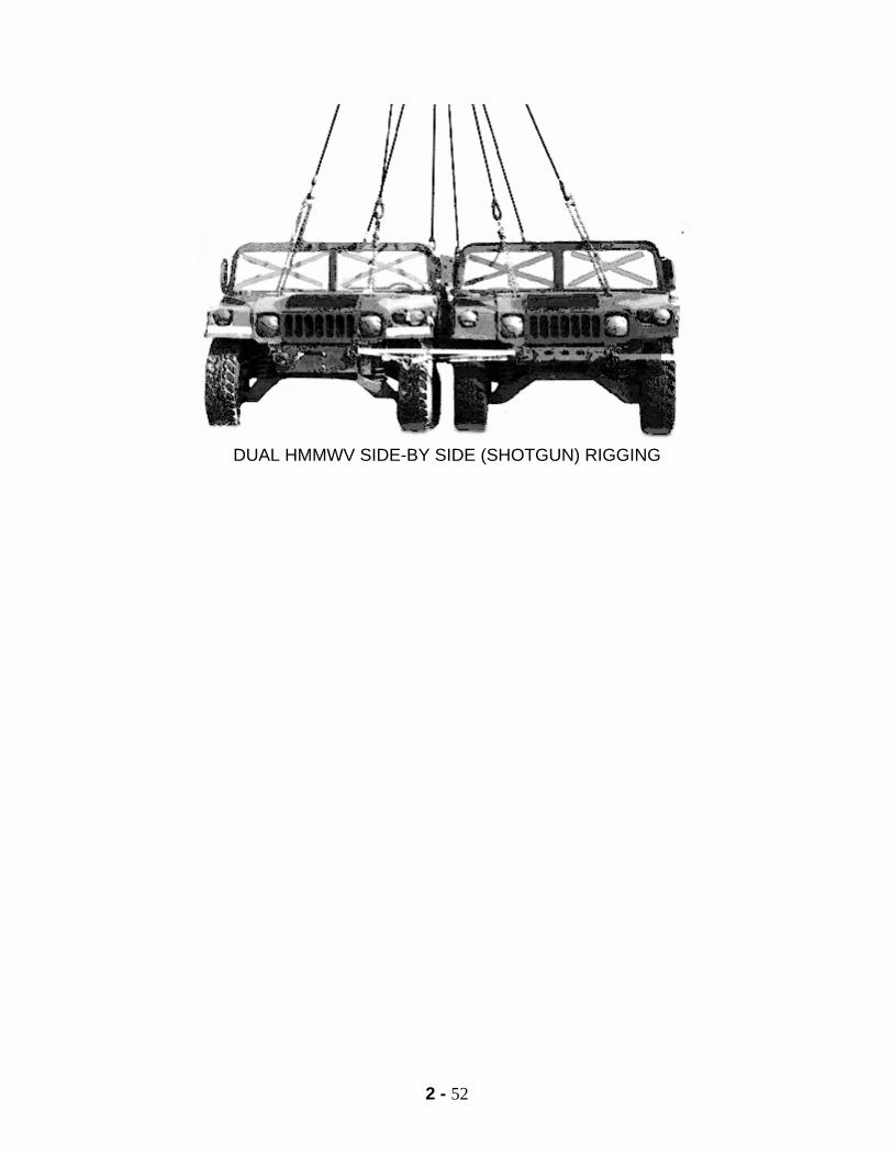
2 - 52
DUAL HMMWV SIDE-BY SIDE (SHOTGUN) RIGGING

2 - 53
NOTES
2 - 54
M119A2 105mm HOWITZER Forward / Firing Position, Platform Down.
1. APPLICABILITY
Those rigging procedures have been approved by the US Army NATICK for flight by UH-60 & CH-47 at 110 kts.
2. LOAD DESCRIPTION: WEIGHTS
MAXIMUM with 10K sling set: 4690 lbs.
MAXIMUM with accompanying load w/ 25K sling set: 7690 lbs.
MAX ACCOMPANYING LOAD: 3000 lbs.
3. MATERIALS
10,000lbs capacity sling set
Tape, adhesive, pressure-sensitive, 2 inch wide roll.
Webbing, cotton, ¼ inch, 80lbs breaking strength Cord, nylon, Type III, 550lbs breaking strength
Cord, nylon, Tubular, ½ inch, 1000lbs breaking strength
Appropriate padding material Strap, tie-down, CGU-1B Clamp, chain link
4. PERSONNEL: Two people can prepare and rig the load in 30 minutes.
PHASE I (PART 1) PREPARATION
1. Begin preparing the load at any point and continue around in a 360 degree motion
until you return to your start point either clockwise or counterclockwise. 2. You will place the Howitzer in the forward/firing configuration. Place the tube in
forward travel lock and secure it with the pushpins.
2 - 55
3. Place the howitzer on the firing platform and secure it with the front and rear stays with push pins, once you tighten your front stays with the saddle clamp, you will secure the clamp with type III nylon.
4. Pad the machined surface on the cross member. 5. Additionally secure the firing platform with a CGU-1B, by routing it through the lifting
holes and through the cradle of the howitzer. Ensure the CGU-1B is routed across the padding material on that machined surface.
6. Place the muzzle cover on the muzzle and secure it with the strap provided. 7. Pad the nitrogen reservoir with enough material to protect it from being damaged by
the sling legs when the A/C picks up the load. 8. Take a piece of type III nylon, approximately 8 to 10 feet long and route it through
the hole portion of the cross bar on either side. Pull it tight and wrap it one complete time around the hex portion of the equilibrator shaft. Keeping it tight, you will wrap it around the buffer assembly. From the buffer you take the type III to the equilibrator shaft on the opposite side, and wrap it one complete time. Take it down through the hole portion of the cross member on the opposite side and secure it with a non-slip secure knot. This is done to prevent the sling legs from becoming caught on the equilibrator shafts and the buffer assembly.
9. Place brakes in the on position. 10. Place covers on equilibrators and secure them with straps provided. 11. Rotate the gunner's site mount all the way back and in. Place the mount cover over
the mount and secure it with the strap provided and additionally secure the cover with type III nylon to a fixed portion of the load.
12. Install the run-back stop in the breech, and place the breech cover over it while
securing it with the strap provided. Additionally secure cover with type III nylon to a fixed portion of the load.
13. Take a piece of type III nylon, approximately 8 to 10 feet long and tie it to left trail.
Pull it tight and place through the hole portion on the back of the equilibrator. Keeping it tight, you will go to the opposite trail. From that trail you will take the nylon through the hole portion of the opposite equilibrator, and tie it back to the original tie down point.
14. Ensure firing platform clamps are hand tight. 15. Jack strut secured with pin and additionally secured with 2" tape.
2 - 56
16. Rear brake assembly padded. 17. Detachable spade secured with large pins and secured from pin to pin with type III
nylon. 18. Trail hand spike placed in the mounts provided and secured in two places with 2"
tape. 19. Ensure knock off hub is parallel with the ground.
PHASE I (PART 2) RIGGING
1. Place three sling legs on the apex. Take fourth sling leg and remove the lifting
chain. Add that lifting chain to the middle sling leg on apex. Place the sling set on top of load.
2. Secure the free running end of left sling leg, route the chain around the center
portion of the left tire. Secure a link count of 55. Additionally secure chains with chain clamp or ½ tubular nylon. Secure excess links with type III nylon.
3. Secure the free running end of the center sling leg, route the chain through the
towing lunette, securing a link count of 35. Additionally secure the excess with type III nylon.
4. Secure the free running end of the right sling leg, route the chain around the knock
off hub of right tire. Secure a link count of 50. Additionally securing the excess links with type III nylon. Ensure the knock off hub is parallel to ground.
5. One cluster breakaway located on M90 chronograph mount. Second breakaway
located on bar portion of rear travel lock assembly. Third breakaway is located on base portion behind the brake assembly above the lunette.
PHASE II
INSPECTION OF PREPARATION AND RIGGING
1. There are three personnel qualified to inspect this load. They are as follows:
a. Pathfinder School Graduate b. Air Assault School Graduate c. SLICC (Sling Load Inspector Certification Course) Graduate
2 - 57
2. When you inspect this load, you will start at one end of the load and work in a 360 degree manner and from top to bottom. If you find a deficiency, you will stop and correct that deficiency, and restart your inspection process from there. Inspect a minimum of two times and until you are 101% sure the load will fly safely.
3. The inspection sequence is as follows:
a. Muzzle cover secure on muzzle b. Recuparator padded and secured with type III nylon
c. Type III nylon spider web present
d. Travel lock secured with push pins provided
e. Saddle clamp in the up position and secured with type III nylon
f. Machined plain padded
g. CGU-1B present with no twist, ratchet portion secured with 2" tape, excess rolled
and additionally secure with 2" tape
h. Brake on
i. Link count left side 55, excess secured with type III nylon
j. Chain clamp or ½ tubular nylon (2 square knots) present on chains, additionally secured with 2" tape
k. Equilibrator cover present
l. Castellated nut and cotter pin
m. Apex order, left-to left, right-to-right, center-to-rear
n. Sling legs routed properly
o. Breakaway (each leg wrapped individually)
p. Gunners sight mount cover secured with strap and additionally with type III nylon
q. Rear stays secure with push pins
r. Spider web rear: line X line
2 - 58
s. Breech cover secured with strap and additionally with type III nylon
t. Run back stop present
u. Firing platform clamp secured
v. Jack strut secure and additionally with 2" tape
w. Link count rear 35, excess secured with type III
x. Breakaway around travel lock bar
y. Brake on
z. Brake assembly padded
aa. Breakaway
bb. 1 chain through rear lift point
cc. Detachable spade secured with type III nylon
dd. Firing Platform clamp secured
ee. Trail hand spike secured in two places with 2" tape
ff. Rear stays secure with push pins
gg. Equilibrator cover present
hh. Brake on
ii. Knock off hub parallel to ground
jj. Link count right side 50, excess links secured with type III nylon
kk. Clamp or ½ tubular nylon (2 square knots) (NOTE: DA Form 7382-R must be filled out IAW FM 4-20.197 see Appendix I.)
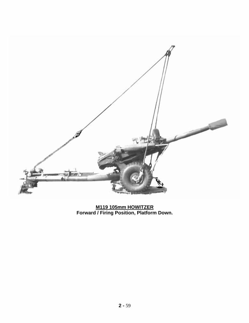
2 - 59
M119 105mm HOWITZER
Forward / Firing Position, Platform Down.
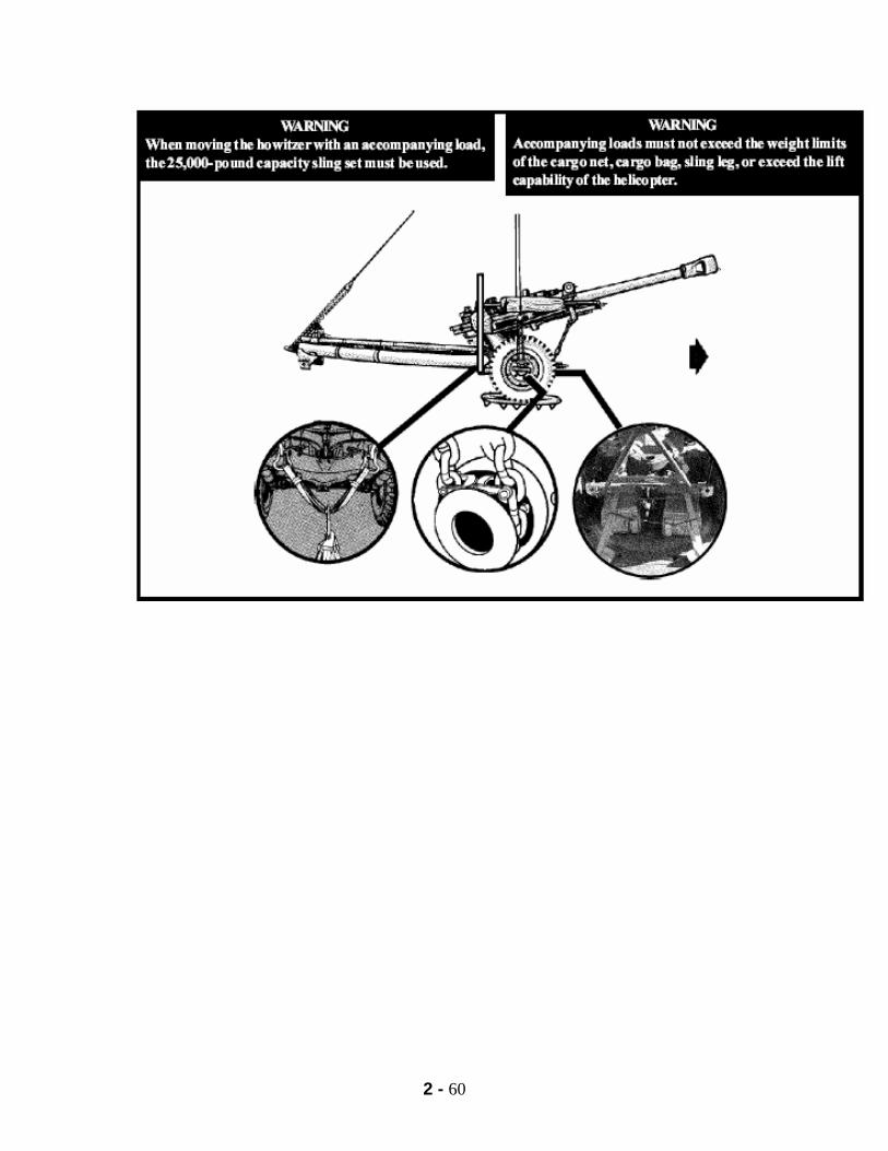
2 - 60

2 - 61
NOTES
2 - 62
PART III SUITABLE SLING LOADS
M149-SERIES WATER TRAILER
1. APPLICABILITY. This load is suitable for CH-47 helicopters at airspeeds up to and including 80 knots. 2. LOAD DESCRIPTION. Trailer, water, 400 gallon, M149-series, with original lift provisions, LIN W98825. Weight: EMPTY LOADED M149 2,540 lbs. 6,060 lbs. (see Warning) M149A1 2,540 lbs. 6,060 lbs. (see Warning) M149A2 2,800 lbs. 6,320 lbs. (see Warning)
WARNING The M149, M149A1, and M149A2 water trailer without modified clevis-type lift provisions are not currently certified for Slingload Operations due to inadequate lift provision strength when the trailer is loaded. 2. MATERIALS. a. Sling set (10,000 lbs. capacity). b. Tape, adhesive, pressure-sensitive, 2 inch wide roll. c. Cord, nylon, Type III, 550 lbs. breaking strength. d. Webbing, cotton, 1/4 inch, 80 lbs. breaking strength. 3. PERSONNEL: Two personnel can prepare and rig this load in 10 minutes.
PROCEDURES
PHASE I (PART 1)
PREPARATION 1. Secure the light cable and air hoses to the drawbar with tape or type III nylon. 2. Place the support leg and wheel in the down and locked position. Secure raising handle with Type III nylon. 3. Secure faucet boxes with the latches provided and additionally with Type III Nylon.
2 - 63
4. Secure safety chains to handles with Type III Nylon. 5. Shatterproof reflectors and brake lights with 2 inch tape. 6. Tape the top edge of the aft end of the water tank to prevent the sling legs from chafing on the top of the tank. 7. Engage both hand brakes. 8. Make sure that the fill port is securely closed. Tape if necessary. 9. Water trailer must be empty or full.
PHASE I (PART 2)
RIGGING
1. Position apex on top of the tank. Route the outer sling legs to the front of the trailer and the inner sling legs to the rear. 2. Route the free running ends of the front chain legs through the lunette front eye and insert a link count of 75 in the grabhook assembly. 3. Using the rear lift provisions as a guide to keep the chains in place, route the free running end of the left chain leg down between the tank and the crossmember, under the rear crossmember and back up through the lift provision. Secure a link count of 90 in the grabhook assembly. Repeat the same process on the right side. 4. Secure all excess chain with type III nylon. 5. Tie a cluster breakaway on all four sling legs with one turn 1/4” cotton webbing on top of water tank to prevent entanglement during hook up.
PHASE II
INSPECTION
Begin inspection sequence at the towing lunette
1. Inspect for a link count of 75 on both chain legs. a. Excess chain secured. b. Light cable secured.
2 - 64
c. Air hoses secured. d. Support leg and wheel in down position. e. Right hand brake engaged. 2. Move around the right side of the load. a. Right rear link count of 90. b. Excess chain secured. 3. Step up onto right rear bumper. a. Top edge of trailer taped and padded. b. Fill port secured. c. Trailer full or empty. d. Cluster breakaway 1/4 inch cotton webbing around all four sling legs. e. Apex order, outer front, inner rear. f. Castellated nut, cotter pin. 4. Move to the left rear lift point. a. Left rear link count 90. b. Excess chain secured. c. Left hand brake engaged.
(NOTE: DA Form 7382-R must be filled out IAW FM 4-20.197 see Appendix I.)
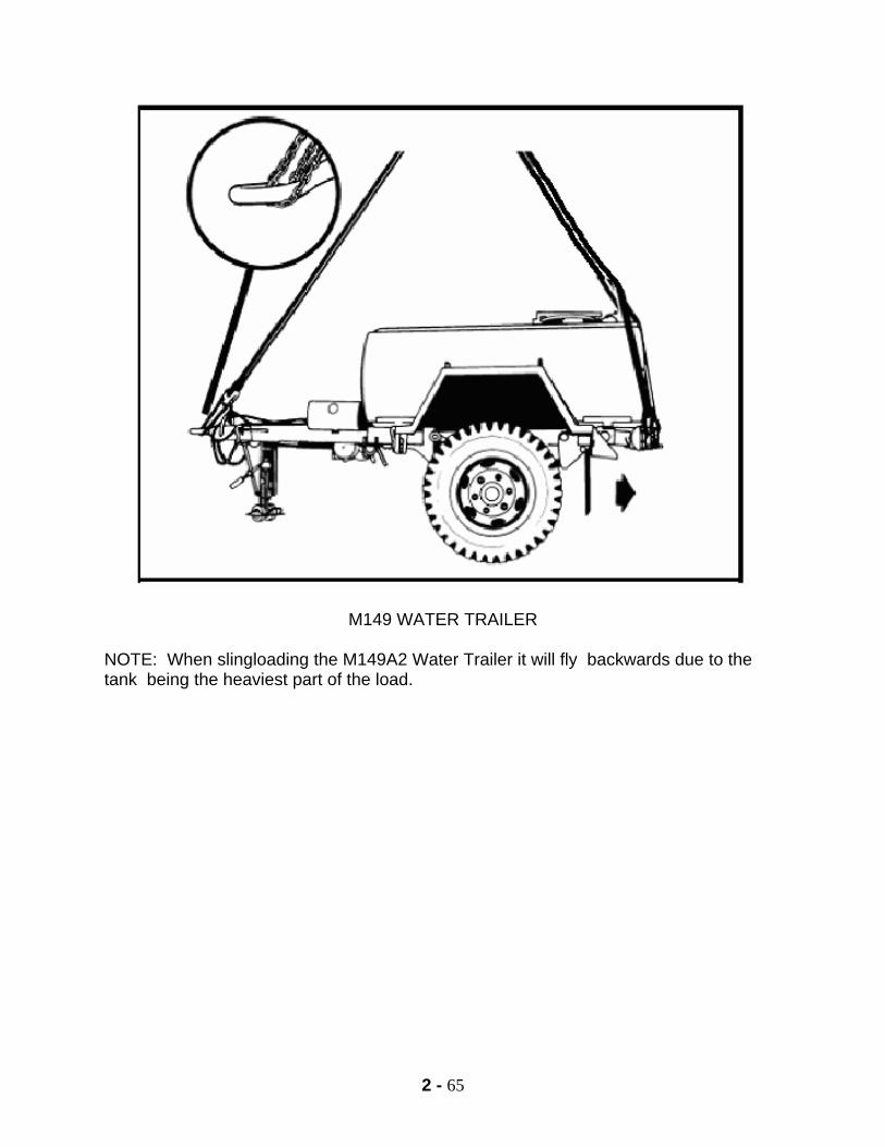
2 - 65
M149 WATER TRAILER
NOTE: When slingloading the M149A2 Water Trailer it will fly backwards due to the tank being the heaviest part of the load.

2 - 66
NOTES
2 - 67
M1097/M1097A2 TRUCK, CARGO, 1 1/4-TON (HMMWV) a. Applicability. Certified by US Army NATICK for CH-47 helicopter at airspeeds up to and including 90 knots. NOTE: This vehicle cannot be flown by a UH-60 when ACL exceeds 4,100 pounds. b. Load Description. 1. M1097 truck, 1 1/4 ton (HMMWV) 2. M1097A2 truck, 1 1/4 ton (HMMWV) 3. Weight a. Empty: 5,900 lbs. b. ACL: 4,400 lbs. c. Loaded: 10,300 lbs.
d. Materials. 1. Extended Slingset (25,000 lbs. capacity). 2. Tape, adhesive, pressure-sensitive, 2-inch wide roll. 3. Cord, nylon, Type III, 550 lbs. breaking strength. 4. Webbing, cotton, 1/4 inch, 80-pound breaking strength.
e. Personnel. Two people can prepare and rig the load in 15 minutes.
PHASE I (PART 1)
PREPARATION 1. Begin preparing the load at any point and continue around in a 360-degree motion until you return to your start point either clockwise or counterclockwise. Start at the passenger side windshield.
2 - 68
2. The windshield will be taped and padded IAW your unit SOP. At minimum make an X configuration with two-inch tape both inside and outside. Rotate the mirrors forward towards the windshield and secure them with type III nylon. Inspect your front lift points for any rust, dents, cracks, nicks, and burrs. 3. The hood will be secured with latches provided and two-inch tape. Wheels will be in the straightforward position. All glass and plastic, i.e. turn signals and headlights will be taped IAW your unit SOP. Again, the other side of the hood will be latched and taped with two-inch tape. You now come to the other rearview mirror. It also is rotated forward and secured with type III nylon and the windshield is shatterproof with two-inch tape in an X configuration both inside and outside. The ends of the vehicle bumper guides will be padded with two-inch tape or antenna balls. 4. Now, when preparing the interior of the vehicle, work your way from the inside towards the outside. 5. Start with the transmission and make sure it is in neutral. Check the hand brake and make sure it is in the engaged position. The steering wheel will be secured with type III nylon to a fixed portion of the load in at least two places. Also, make sure that electrical switches and the engine ignition switch are in the off position, and check for a proper fuel level of 75 % or less. The last thing to prepare on the inside is the seat belts. The male portion must be rolled, taped and tucked behind the seat and the female portion will be rotated up behind the data plate and taped in place with two-inch tape. If the vehicle has the three-point lap belt, it will be secured as worn. All canvas doors and other cargo will be secured in the rear of the vehicle. 6. Move towards the rear. The troop seats will be up and secured with the pins provided. If one of the pins is missing, the troop seat will be secured with type III nylon in two places. All glass and plastic will be taped and padded IAW your unit SOP. Rotate the tailgate to the up position, secure it with the hooks and chains provided and secure the hooks with type III nylon. The sling guides will be padded IAW your unit SOP. 7. Inspect your rear lift points for any rust, dents, cracks, nicks, or burrs. If any are present, take the appropriate action. Ensure the towing pintle is closed and secured with a cotter pin, two-inch tape, or type III nylon. The electrical connector needs to be spring loaded and have a rubber gasket in it. If no gasket is found, tape it closed with two-inch tape. 8. Move around the other side of the vehicle and the first thing you should come to is the fuel cap. You will roll, tape and tuck the male portion of the seat belt behind the seat and rotate the female portion up behind the seat and the data plate and tape it with two-inch tape. If the vehicle has the three-point lap belt, it will be secured as worn.
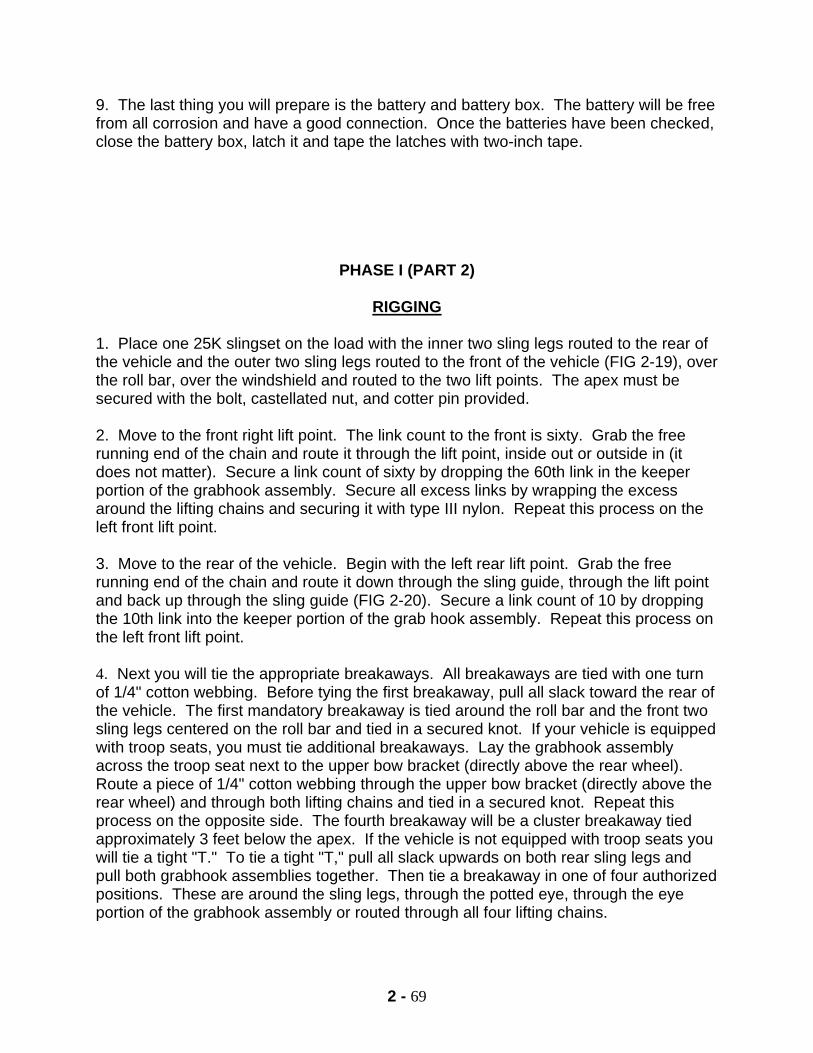
2 - 69
9. The last thing you will prepare is the battery and battery box. The battery will be free from all corrosion and have a good connection. Once the batteries have been checked, close the battery box, latch it and tape the latches with two-inch tape.
PHASE I (PART 2)
RIGGING 1. Place one 25K slingset on the load with the inner two sling legs routed to the rear of the vehicle and the outer two sling legs routed to the front of the vehicle (FIG 2-19), over the roll bar, over the windshield and routed to the two lift points. The apex must be secured with the bolt, castellated nut, and cotter pin provided. 2. Move to the front right lift point. The link count to the front is sixty. Grab the free running end of the chain and route it through the lift point, inside out or outside in (it does not matter). Secure a link count of sixty by dropping the 60th link in the keeper portion of the grabhook assembly. Secure all excess links by wrapping the excess around the lifting chains and securing it with type III nylon. Repeat this process on the left front lift point. 3. Move to the rear of the vehicle. Begin with the left rear lift point. Grab the free running end of the chain and route it down through the sling guide, through the lift point and back up through the sling guide (FIG 2-20). Secure a link count of 10 by dropping the 10th link into the keeper portion of the grab hook assembly. Repeat this process on the left front lift point. 4. Next you will tie the appropriate breakaways. All breakaways are tied with one turn of 1/4" cotton webbing. Before tying the first breakaway, pull all slack toward the rear of the vehicle. The first mandatory breakaway is tied around the roll bar and the front two sling legs centered on the roll bar and tied in a secured knot. If your vehicle is equipped with troop seats, you must tie additional breakaways. Lay the grabhook assembly across the troop seat next to the upper bow bracket (directly above the rear wheel). Route a piece of 1/4" cotton webbing through the upper bow bracket (directly above the rear wheel) and through both lifting chains and tied in a secured knot. Repeat this process on the opposite side. The fourth breakaway will be a cluster breakaway tied approximately 3 feet below the apex. If the vehicle is not equipped with troop seats you will tie a tight "T." To tie a tight "T," pull all slack upwards on both rear sling legs and pull both grabhook assemblies together. Then tie a breakaway in one of four authorized positions. These are around the sling legs, through the potted eye, through the eye portion of the grabhook assembly or routed through all four lifting chains.
2 - 70
PHASE II
INSPECTION OF PREPARATION AND RIGGING 1. The only personnel qualified to inspect this load are a Pathfinder School Graduate, SLICC (Sling Load Inspector Certification Course) Graduate, or an Air Assault School Graduate. You will inspect this load at least twice or until you are 101% sure that it will fly safely. Your inspection will start on the passenger side of the vehicle. 2. First, inspect the windshield and make sure it is properly shatter-proofed. Then, check the mirrors and make sure they are rotated forward and secured with type III nylon. Check the hood latches to make sure they are secured and taped with two inch tape and that the wheel is straight. 3. Then check all the glass and plastic in the front and make sure it is taped and padded IAW unit SOP. Moving to the other side you once again check to see that the wheels are straight, the hood is latched and taped with two-inch tape, the mirrors are rotated forward and secured with type III nylon and that the windshield is shatterproof with two-inch tape in an X configuration both inside and out. 4. On the inside of the vehicle check the transmission and make sure that it is in neutral and the parking brake is engaged. Then check all the electrical switches and the engine ignition switch to make sure they are off, and the fuel level is 75 % or less. Check to ensure the steering wheel is secured with type III nylon to a fixed portion of the load and then check the seat belts. Make sure the male portion is rolled, taped and tucked, and that the female portion is rotated up behind the data plate and taped with two-inch tape. If the vehicle has the three-point lap belt, it will be secured as worn. 5. Move to the rear of the load and inspect the troop seats to ensure that they are secured in the up position with the pins provided, or secured in two places with type III nylon. At the rear of the vehicle you will inspect a vehicle with troop seats in a U shaped sequence. Begin by inspecting for a link count of three. Move to the breakaway and inspect for 1/4" cotton webbing. Ensure the tailgate is secured with the hooks and chains and that the hooks are secured with type III nylon. Inspect glass and plastic for tape and padding IAW unit SOP. Ensure chains are routed through the lift point. Inspect the towing pintle to ensure that it is secured closed with the cotter pin or two inch tape or type III nylon. Check the electrical connector for a rubber gasket and ensure it is spring loaded. Moving to the front, ensure the chains are routed through the lift point. Inspect glass and plastic for tape and padding. Ensure the tailgate is secured with the hooks and chains and the hooks are secured with type III nylon. Ensure breakaway is tied with 1/4” cotton webbing. Inspect for a link count of three. If the vehicle is not equipped with troop seats, begin at the breakaway using the same sequence as discussed above. Upon completion of the rear inspection, move down the
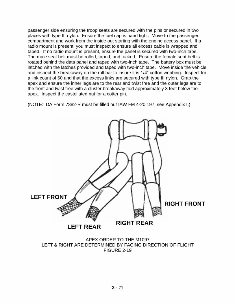
2 - 71
passenger side ensuring the troop seats are secured with the pins or secured in two places with type III nylon. Ensure the fuel cap is hand tight. Move to the passenger compartment and work from the inside out starting with the engine access panel. If a radio mount is present, you must inspect to ensure all excess cable is wrapped and taped. If no radio mount is present, ensure the panel is secured with two-inch tape. The male seat belt must be rolled, taped, and tucked. Ensure the female seat belt is rotated behind the data panel and taped with two-inch tape. The battery box must be latched with the latches provided and taped with two-inch tape. Move inside the vehicle and inspect the breakaway on the roll bar to insure it is 1/4” cotton webbing. Inspect for a link count of 60 and that the excess links are secured with type III nylon. Grab the apex and ensure the inner legs are to the rear and twist free and the outer legs are to the front and twist free with a cluster breakaway tied approximately 3 feet below the apex. Inspect the castellated nut for a cotter pin.
(NOTE: DA Form 7382-R must be filled out IAW FM 4-20.197, see Appendix I.)
APEX ORDER TO THE M1097 LEFT & RIGHT ARE DETERMINED BY FACING DIRECTION OF FLIGHT
FIGURE 2-19
RIGHT FRONT
LEFT REAR RIGHT REAR
LEFT FRONT
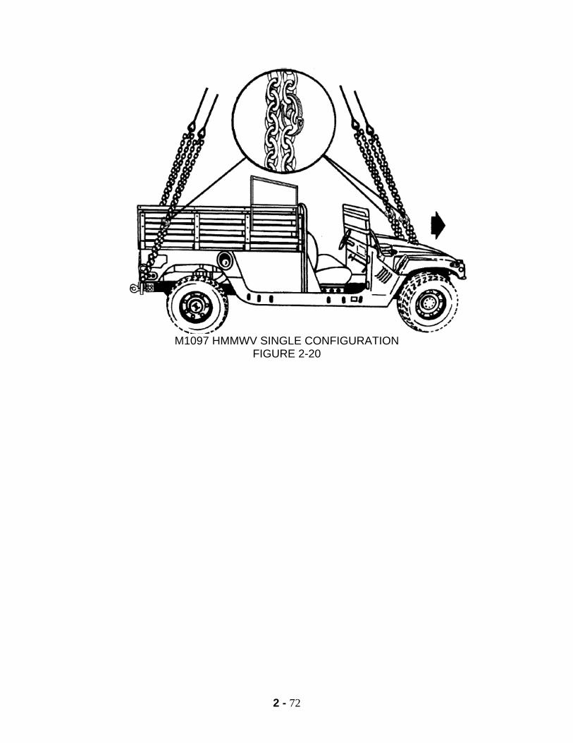
2 - 72
M1097 HMMWV SINGLE CONFIGURATION
FIGURE 2-20

2 - 73
NOTES
2 - 74
PART IV UNIQUE (NON-STANDARD) SLING LOADS
A. CLASSIFICATION DEFINITIONS OF SLING LOADS 1. Certified Sling Loads. Certified sling loads are those items of equipment and their associated rigging procedures which have completed the evaluation and testing required for sling load certification. These rigging procedures are in FM 4-20.197 and FM 10-450-4/5. The following restrictions apply to certified for sling loads: a. The load must be within the lifting capability of the desired helicopter model and not exceed the rated capacity of the sling set being used. b. The load shall be rigged in accordance with the certified rigging procedure. c. The recommended stable airspeed specified for the load in the applicability section of the rigging procedure is a recommendation and not a restriction, unless so stated. NOTE: When carrying loads at weights close to the aircraft hook limitations, close coordination with the aviation unit is required. 2. Suitable Sling Loads. Suitable sling loads are those items of equipment and their associated rigging procedures that have not been certified but have demonstrated acceptable static lift and flight characteristics during a flight test. In most cases these loads were not pull tested in accordance with MIL STD 913, but are known loads which have been flown without incident for years and which are considered to be proven safe. These rigging procedures can be found in FM 4-20.197 and FM 10-450-4/5. 3. Unique Sling Loads. Unique loads are equipment carried on a one time or low-frequency basis, such as telephone poles, artillery targets, or barrier material. The lack of sling load certification in itself does not preclude a unit commander from carrying a load that is not certified. 4. Prohibited Sling Loads. Prohibited sling loads are items of equipment that are prohibited from sling loading. These loads have been denied sling load certification and are a safety hazard if carried. They have either structural deficiencies or have exhibited unstable flight characteristics during flight testing. B. SLING LOAD OF UNIQUE ITEMS OF EQUIPMENT: Helicopter sling loading of unique items, due to operational requirements, will be at the discretion of the commander. Equipment not listed in FM 4-20.197 and FM 10-450-4/5 should be static lifted (when possible) by a crane to determine proper rigging and stability characteristics. Personnel thoroughly familiar with sling load rigging procedures
2 - 75
should assist in the static lift testing/ rigging and hookup. Flight evaluating may be conducted after a satisfactory static rigging configuration has been determined. Other examples of unique sling loads: Destroyed or mired vehicles Construction materials Downed aircraft will be rigged using procedures in FM 3-04.513 Battlefield Recovery and Evacuation of Aircraft, dated 27 September 2000. TECHNIQUES FOR RIGGING A UNIQUE LOAD: SAFETY NOTE: This is only a technique and not a doctrinal method of conducting sling load operations. The Sabalauski Air Assault School and the 101st Airborne Division (Air Assault) assume no liability in the sling load of unique loads while using this technique. Rigging and sling loading unique loads is inherently dangerous and should only be conducted by the most qualified and experienced personnel and crews, when the mission dictates, there is no other way to accomplish the same mission, and the commander has conducted a thorough risk assessment with appropriate risk reduction measures applied. The commander with “high” risk approval authority (O-6) is the approval authority for flying non-standard loads. 1. Acquire suitable air items and special equipment such as a sling set of appropriate capacity, applicable apex setup for the aircraft to be used, additional chains, tie down and break away material, A7A straps, ADS slings, clevises, etc. 2. Determine if the load is structurally sound and strong enough to be lifted and sling loaded. 3. Determine center of balance of load. Consider that the heaviest portion will fly forward. 4. Determine suitable lifting points on the load. Must be strong enough to lift the load and will allow the air items (sling legs and chains) to routed in a manner that will not damage them. 5. Determine link count. Start with 3. This will provide the most distance between the load and the aircraft on the initial pick up attempt in the event the load shifts or rolls. It also makes adjustments quickly and easily because the hookup team will only need to shorten the appropriate legs, if required, instead of both lengthening & shortening. 6. Use extended sling legs if possible/feasible. This will reduce the amount of time the A/C needs to spend hovering over the load, as it can land next to the load while link count & rigging procedures are modified, and creates more space between the load & A/C.
2 - 76
7. Hook up using the appropriate techniques then clear the hookup team from the load. The signal person then has the aircraft move upward slowly, take up slack in the sling legs, and begin to lift the load. At the same time, all hookup team members observe the load. If at anytime the load appears to become unstable, unbalanced, or structurally weak, the signal person will immediately indicate to move the load back down, and cut sling load. The hookup team moves back to the load, and attempts to fix the problem, if possible. This process may have to be repeated several times until the desired result is achieved. Whenever possible, there should be ground to air communication between the ground crew and pilot. NOTE: Low density equipment with low weight and large surface area (flat surfaces), such as shelters, empty trailers, pallet loads, boat shaped items, and empty fuel or water drums, are likely to become extremely unstable when flown during sling load operations, even at low airspeeds, and should be flown with extreme caution.
3 – 1
CHAPTER THREE
PART I
RAPPELLING
1. REFERENCES.
a. TC 21-24, RAPPELLING, dated September 1997. b. USSOCOM Reg 350-6, dated 25 August 2004 c. FM 3-97.61 Military Mountaineering, dated August 2002
2. EQUIPMENT. a. Rope, climbing, nylon, NSN 4020-00-931-8793. 1. 120 feet in length. 2. 7/16 inches in diameter. 3. 3 strand, multi-filament, twisted with a right-hand lay. 4. 4,500 pounds of tensile strength (15 percent less when wet, knotted or frozen). 5. It will stretch 1/3 of its length. b. Rope, sling. This is the rope used to construct the Swiss and Australian rappel seats. Cut a 120 foot nylon climbing rope into 12 to 15 foot sections to make the seats. c. Link, snap, mountain piton, NSN 8465-00-360-0228, 2,000 lbs. capacity with the gate closed. Steel, non-locking. d. Glove, leather, workman's, NSN 8415-00-268-7868. e. Insert, wool glove, OG-208, NSN 8415-00-682-6577. 3. PERSONNEL. a. The following are the minimum personnel required to conduct rappelling operations from towers, ground, or aircraft: 1. Rappel Safety NCOIC or OIC – SFC or above. Air Assault or Ranger qualified. Must have commo with A/C and other required agencies, such as range control or higher HQ. 2. Rappel Master – Responsible for safety of rappellers. There must be a qualified Rappel Master in each aircraft and one with each tower rappel site at all times. A qualified Rappel Master must be a CPL or above and graduate of both the Air Assault Course and the Rappel Master Course. A qualified Rappel Master must maintain currency by performing duties at least once every six months. If a rappel master
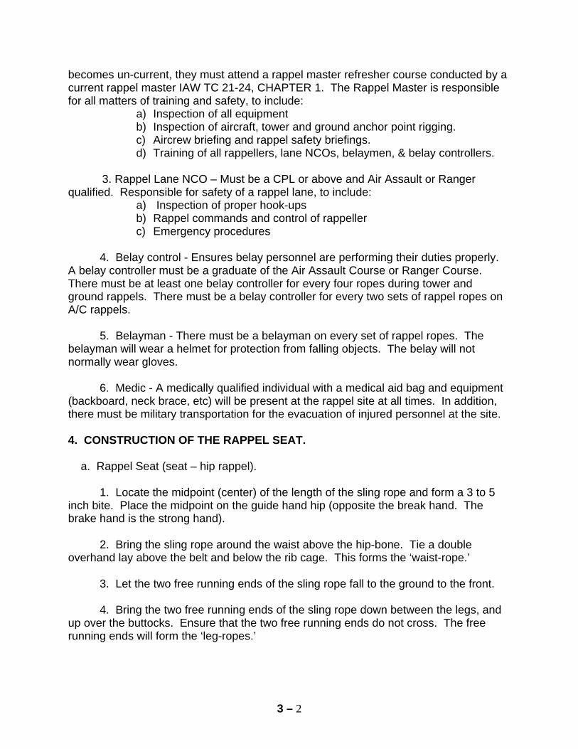
3 – 2
becomes un-current, they must attend a rappel master refresher course conducted by a current rappel master IAW TC 21-24, CHAPTER 1. The Rappel Master is responsible for all matters of training and safety, to include:
a) Inspection of all equipment b) Inspection of aircraft, tower and ground anchor point rigging. c) Aircrew briefing and rappel safety briefings. d) Training of all rappellers, lane NCOs, belaymen, & belay controllers.
3. Rappel Lane NCO – Must be a CPL or above and Air Assault or Ranger qualified. Responsible for safety of a rappel lane, to include:
a) Inspection of proper hook-ups b) Rappel commands and control of rappeller c) Emergency procedures
4. Belay control - Ensures belay personnel are performing their duties properly. A belay controller must be a graduate of the Air Assault Course or Ranger Course. There must be at least one belay controller for every four ropes during tower and ground rappels. There must be a belay controller for every two sets of rappel ropes on A/C rappels. 5. Belayman - There must be a belayman on every set of rappel ropes. The belayman will wear a helmet for protection from falling objects. The belay will not normally wear gloves. 6. Medic - A medically qualified individual with a medical aid bag and equipment (backboard, neck brace, etc) will be present at the rappel site at all times. In addition, there must be military transportation for the evacuation of injured personnel at the site. 4. CONSTRUCTION OF THE RAPPEL SEAT. a. Rappel Seat (seat – hip rappel). 1. Locate the midpoint (center) of the length of the sling rope and form a 3 to 5 inch bite. Place the midpoint on the guide hand hip (opposite the break hand. The brake hand is the strong hand). 2. Bring the sling rope around the waist above the hip-bone. Tie a double overhand lay above the belt and below the rib cage. This forms the ‘waist-rope.’ 3. Let the two free running ends of the sling rope fall to the ground to the front. 4. Bring the two free running ends of the sling rope down between the legs, and up over the buttocks. Ensure that the two free running ends do not cross. The free running ends will form the ‘leg-ropes.’
3 – 3
5. Pass the ends of the rope over then behind the rope that is tied around the waist (waist-rope) at the two points above the centers of the two rear seat pockets, resulting in the ‘leg-ropes’ being routed from top– to- bottom behind the waist-rope. Ensure that the free running ends are running towards the center of the buttocks, and are between the waist-rope and the rappeller’s body. 6. Grab the free end of the rope that is on the left side of the body with the left hand, and the free end of the rope that is on the right side of the body with the right hand. 7. Squat down and simultaneously pull down on both running ends of the ropes and stand up. This will tighten the seat. 8. Take the two free running ends of the rope and route them over the top of the waist rope, forming two half hitches over the leg ropes. 9. Tie the two running ends into a square knot with overhand knots securing each side of the square knot. The square knot is tied on the opposite side of the body from the brake hand.
FIGURE 3-1
10. Place any excess rope in the trouser pocket near the square knot. 11. With the gate down and the hooked end of the snaplink against the navel, place the snaplink through the single rope that is around the waist and the two ropes forming the double overhand lay. 12. Rotate the snaplink a half turn so that the gate is facing up and will open away from the body.
3 – 4
5. RAPPELLER PREPARATION. a. Shirt tails, loose clothing, and equipment straps must be secured. Sleeves will be rolled down. b. Helmets will be worn during rappelling. All straps will be properly fastened and the helmet will be in serviceable condition. c. Heavy leather workman's gloves will be worn when rappelling. Glove inserts are worn when rappelling from aircraft or as determined by the unit leaership. d. Rappellers will have identification tags and I. D. card e. Eye and ear protection will be worn when rappelling from a helicopter. f. When rappelling with equipment, LBE or LBV should be unfastened in the front or fastened loosely behind the back of the rappeller. The rucksack should be worn high and tight on the back of the rappeller to allow the brake hand to reach the small of the back. Rucksack adjustment straps will be tied across the chest or tucked away g. The rappellers weapon will be slung diagonally across the back, muzzle down near hip on guide hand side, with the weapon’s butt stock on the brake hand side near the shoulder. 6. RAPPEL HOOK-UP PROCEDURES. a. Seat – Hip Rappel Hookup 1. The rappeller's square knot with two overhand knots should be facing the anchor point. 2. Grasp the two ropes with both hands and drop the two ropes through the gate of the snaplink. At this point, there should be two (2) ropes running through the snaplink. 3. Using the hand closest to the anchor point, pull slack towards the anchor point, rotate the slack down under and over the top of the snaplink. 4. Drop the two ropes a second time through the gate of the snaplink. At this point there should be four (4) ropes running through the snaplink. 5. If the rappeller weighs more than 200 pounds or is carrying equipment in excess of 50 pounds, he should consider using a friction hookup. This is accomplished by repeating step three and four. At this point there should be six (6) ropes running through the snaplink.
3 – 5
6. Place the guide hand on the rope between the anchor point and the snaplink, palm facing skyward. 7. Place the brake hand around the running end of the rope, palm facing downward, and place the brake hand with the rope in the small of the back. 7. RAPPEL COMMANDS. a. Verbal and Hand and Arm Signals for Tower or Ground Rappels. 1. Get Ready. Extend both arms to your front with elbows locked, fists clenched and thumbs pointing upward. 2. Position. a) Primary method. Extend both arms to the front, elbows bent, forearms pointed upward, fists clinched and index fingers pointing upward. Make a circular motion with both forearms rotating in opposite directions. b) Alternate method. Extend both arms to the front with elbows locked, fists clenched and index fingers extended. Bend at the waist so that your arms below your waist. Make a circular motion with arms rotating in opposite directions. 3. Go. Extend an arm with elbow locked, fingers extended and thumb along the index finger and point directly at the rappeller. b. UH-60 Tactical Rappel Commands. 1. On the UH-60, the edge of the floor along the door of the helicopter is used as a pivot point to assume the “L” shaped rappelling position.
2. The commands for a tactical rappel from a UH-60 are as follows: a. Get Ready. Alerts the rappeller. The rappeller and the Rappel Master of the hookup, rappel seat, snaplink and equipment should make final checks. The rappeller also checks his deployment bag to ensure that it is not entangled and that it is ready to toss.
b. Throw Ropes. Keeping his brake hand in the small of his back, the rappeller will toss his deployment bag with ropes OUT AND AWAY from the helicopter with his guide hand. The rappeller will observe that the ropes are touching the ground and are not knotted or entangled. c. Position. Form a squatting position with the brake hand in the small of the back, the rappeller rotates 90 degrees so that he is facing the inside of the aircraft and the Rappel Master. The rappeller then places his heels on the edge of the floor of the
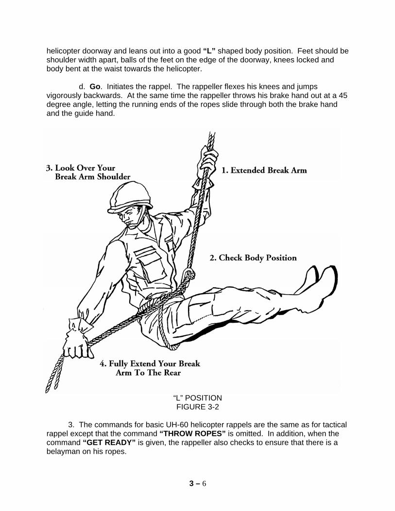
3 – 6
helicopter doorway and leans out into a good “L” shaped body position. Feet should be shoulder width apart, balls of the feet on the edge of the doorway, knees locked and body bent at the waist towards the helicopter. d. Go. Initiates the rappel. The rappeller flexes his knees and jumps vigorously backwards. At the same time the rappeller throws his brake hand out at a 45 degree angle, letting the running ends of the ropes slide through both the brake hand and the guide hand.
“L” POSITION FIGURE 3-2
3. The commands for basic UH-60 helicopter rappels are the same as for tactical rappel except that the command “THROW ROPES” is omitted. In addition, when the command “GET READY” is given, the rappeller also checks to ensure that there is a belayman on his ropes.
3 – 7
8. EXITING THE AIRCRAFT. a. There is one way to exit the aircraft 1. The rappelmaster will send rappellers individually, moving diagonally across the aircraft, i.e., left front, right rear, right front, and left rear. 2. After each rappeller has exited, the rappelmaster will check the rappeler’s descent to ensure he/she is a safe distance below the aircraft, prior to sending the next rappeller. b. The Rappel Master will maintain a minimum of one (1) second delay between rappellers. 9. CONDUCT OF THE RAPPELLING. a. The rappeller will approach the helicopter from the sides of the aircraft. b. Upon boarding the helicopter the rappeller will sit or kneel, hookup and apply his brake hand to the small of his back prior to helicopter ascent. c. Rappellers weighing 200 pounds or more, or are rappelling with equipment in excess of 50 pounds, will use two (2) turns around the snaplink. (There should be six (6) ropes running through the snaplink). d. Rappellers will not step over a rappel rope. e. Rappellers will not exit the helicopter until told to do so by the Rappel Master. f. Rappellers will not release their brake hand from the rappel rope while conducting rappelling. g. During the descent the rappeller will keep his feet together and legs straight while maintaining an “L” shaped body position by bending at the waist (Figure 3-2). h. After leaving the aircraft, the rappeller will maintain eye to ground contact. i. The rappeller will brake a minimum of three (3) times during descent. 10. BELAY. a. A basic rappeller will not be permitted to rappel without a belayman. b. During helicopter rappelling a minimum of 20 feet of rope will be on the ground. The last 20 feet of rappel rope may be color-coded so the Rappel Master and the
3 – 8
rappeller may more rapidly and accurately determine if 20 feet of rope is on the ground. For tower rappelling a minimum of 10 feet of rappel rope will be on the ground. c. The belayman will grasp the rappel ropes with both hands above head and eye level in such a manner as to allow the rappeller to acquire slack and the belayman the ability to quickly apply a downward pull. Gloves will not normally be worn. If the rappeller states “FALLING”, or loses control during descent the belayman will immediately stop the rappeller by pulling the ropes taut. If a soldier is a “fallen rappeller” from an aircraft, the belayman will turn the opposite direction from the aircraft, simultaneously throwing ropes over either shoulder. The belayman will run the direction he/she is facing, creating a “slide for life” for the rappeller by pulling slack from the ropes. d. The belayman will position himself below the anchor point. NOTE: For non-tactical helicopter rappelling, the belayman will maintain control of the ropes at all times. When the aircraft is on the ground the belayman will take a knee 5 meters outside the rotor disk diameter. As the aircraft moves up, the belay will let the rope slide through his hands until the aircraft is 25-30 feet off the ground. At this time the belayman will walk in and position himself under the aircraft. When the aircraft starts down, the belayman will keep the ropes taut and away from the aircraft at a 45 degree angle. Once the aircraft is on the ground, the belayman will work his way to his original position while still maintaining positive control of the rope. e. The belayman will focus his attention on the rappeller and maintain visual contact with the anchor point. f. The belayman will wear a correctly fastened kevlar helmet to prevent injuries from falling rappellers, equipment, etc. 11. EMERGENCY PROCEDURES FOR HELICOPTER RAPPELLING. a. If the helicopter gains altitude above the length of the rappel ropes, the rappeller will immediately brake and lock-in and wait for the descent of the aircraft. Procedures for lock-in are as follows: 1. Place the brake hand in the small of the back and brake to a complete stop. 2. Release the guide hand from the ropes. 3. Bring the guide hand around the back and grasp the running ends of the two rappel ropes behind the brake hand. (Do not release the brake hand.) 4. Using the guide hand, bring the two running ends of the rappel ropes around to the front of the body.
3 – 9
5. Secure these two running ends of the rappel ropes with the two anchor ends of the rappel ropes in your guide hand. This is now your NEW brake hand. 6. Take your old brake hand out of the small of your back. Bring it around to your front and grasp the four ropes (two from the anchor point and the two running ends) either above or below new brake hand. Your old brake hand is now your NEW guide hand. 7. Place your head and eyes back on the Rappel Master to continue the descent, bring the new brake hand to a 90 degree angle to the side. When you want to brake, bring the new brake hand around to your front, diagonally across your chest to your guide hand shoulder. b. In case of an engine failure or an aircraft emergency during rappelling, the rappellers on the ropes will descend as rapidly as possible and move from beneath the aircraft by moving to the sides of the aircraft. If possible, maintain control of the rope to prevent it from entangling in the rotor. The aircraft should move forward and down. 12. MAINTENANCE OF EQUIPMENT. a. A rappel rope is unserviceable if it is saturated with petroleum products, mildewed, excessively frayed or if one, of three, strands is cut more than 1/2 of it's diameter. b. The life of the rappel rope is directly related to the care that the rope receives. Ropes will remain serviceable for approximately 200 rappels under good conditions. To maximize rope life, follow these simple do's and don't s:
DON’T 1. Do not allow a nylon rope to contact heat. 2. Do not smoke around the rope. 3. Do not allow the rope to come in contact with any petroleum based products. 4. Do not store a wet rope without daisy chaining. 5. Do not store a dirty rope without cleaning in a mild soap.
DO 1. Remove all knots after use. 2. Clean and dry after use. 3. Store in a ventilated place. 4. Mountain coil neatly before storage. 5. Inspect the ropes before and after use. c. Records should be maintained on all rappel ropes to indicate the number of times used and the dates used using a DA Form 5752-R. See Appendix H. Unserviceable ropes will be marked, segregated and disposed of properly.
3 – 10
d. Gloves will be checked for holes on the friction bearing surfaces and any holes along the seams. Holes in the friction bearing surface or fingers that expose skin will cause the glove to be unserviceable. e. Snaplinks will be checked for excessive rust and sharp edges inside and out. Opening gates must open and close freely. The pins for the gates must not move left or right and gate must not be able to move past the hook portion. Any of these deficiencies will cause the snaplink to be unserviceable. 13. RAPPEL SAFETY BRIEFING. a. Prior to the conduct of any rappelling, the Rappel Master should give a safety briefing to all personnel. b. This briefing should include as a minimum the following instructions:
TOWER RAPPELLING 1. Loose clothing and equipment will be secured. 2. Rappel seats will be tied by the soldier and inspected by a Rappel Master before climbing the tower. 3. Rappellers will climb the tower only when directed by a Rappel Master. 4. Rappellers will stay in the center of the tower until instructed to move a rappel point. 5. All Rappel Masters, instructors and anyone else standing near the edge of the top of the tower will wear a restraint strap or safety rope attached to an eyebolt on the tower floor or the UH-60 tubular frame. 6. No one will be allowed to lean or sit on the railings or the banisters of the tower. 7. No one will be allowed within three (3) feet of the edge of the tower without being secured, unless moving to a hookup point. 8. When attaching the rappel rope to the snaplink, the slack will always be pulled from the anchor point. 9. Only a qualified Rappel Master will hook up an Australian rappeller.
3 – 11
10. Personnel weighing in excess of 200 pounds will conduct a standard hookup rappel to determine if they require a friction hookup. A friction hookup is created by placing an additional two ropes in the gate of the snaplink (for a total of six ropes in the snaplink). 11. Combat equipment will be positioned on the individual so as not to be in the way of the brake hand. The weapon will be slung diagonally across the back with the muzzle pointing down and on the opposite side of the brake hand and the canteen will be worn on the guide hand hip. Ensure that equipment is worn in a manner that nothing interferes with the placement of the brake hand, or the routing of the rappel rope on the brake hand side to the snap link. 12. Heavy duty gloves are required for all rappels. 13. Kevlar helmets with chin straps fastened will be worn during rappel training. 14. While on the tower or ground hook-up point, the rappeller will maintain eye to eye contact with the Rappel Master and take all commands from him. 15. The rappeller will ensure that he has a belayman on his rope. 16. The belayman will not wear gloves and will keep both hands on the ropes at all times. He will also keep his head and eyes on the rappeller at all times. 17. No slack rappels will be allowed. NOTE: The only slack rappelling to be done will be by a Rappel Master qualified, Air Assault School Instructor for demonstrations and as approved by the Commandant of The Air Assault School. When slack rappel is approved, only 8-10 feet of slack will be coiled. Slack rappelling is to be considered dangerous. 18. All tower rappelling will be done with a double strand of rope. 19. There will be no running on the tower. 20. There will be no smoking or eating near the tower. NOTE: After each rappel, the rappellers must untie, retie, and get reinspected before conducting another rappel.
HELICOPTER RAPPELLING
(Nontactical)
(These areas which apply will be briefed before tactical rappelling) 1. Loose clothing and equipment will be secured.
3 – 12
2. Kevlar helmets will be worn with chin straps fastened. 3. Identification tags and earplugs will be worn. 4. Sleeves will be rolled down. 5. Weapons will be slung diagonally across the back with the muzzle pointing down and on the side opposite the brake hand. 6. A Rappel Master prior to rappelling must inspect all equipment. 7. Personnel will approach and depart a UH-60 helicopter at a 90 degree angle from the side of the aircraft. When approaching or departing the helicopter, personnel will also bend their bodies forward at the waist to ensure clearance of the rotor blades. At no time will personnel go near the rear of the aircraft. 8. Upon boarding the aircraft the rappeller will kneel down in the UH-60, hookup, and apply his brake hand to the small of his back. 9. While in the helicopter, the rappeller will maintain eye to eye contact with the Rappel Master and take all commands from him. 10. The rappeller will ensure that he has a belayman on his rope at all times. 11. During descent the rappeller will maintain eye to ground contact. 12. If the rappeller sees his ropes coming off of the ground or sees that his belayman has lost control of his ropes, the rappeller will immediately brake and execute a lock-in. He will then wait for commands from the Rappel Master. 13. The rappeller will brake a minimum of three (3) times during descent. 14. The belayman will not wear gloves and will keep both hands on the ropes at all times. He will also keep his head and eyes on the aircraft at all times. Positive control of the rappel rope will be maintained by the belayman at all times. 15. All rappelling will be conducted using a double strand of rope. 16. While the helicopter is on the ground the belayman and belaymaster will stay outside of the rotor disk. NOTE : After each rappel, the rappellers must untie, retie, and get reinspected before conducting another rappel.
3 – 13
PART II
FRIES TRAINING (Fast Rope Insertion, Extraction System)
1. REFERENCES. a. USSOCOM regulation 350-6, chapter 6, dated 25 August 2004. b. TC 21-24 Rappelling, September 1997. IMPORTANT SAFETY NOTE: IAW TC 21-24 and USSOCOM Reg 350-6, Headquarters, Department of the Army policy specifies that FRIES is NOT approved for Army-wide use and names the Commanding General, United States Army Special Operations Command (CG USASOC) as the executive agent for FRIES doctrine. The use of FRIES is restricted to special operations forces, pathfinders, long range surveillance units, and HQDA schools with a USASOC-approved FRIES program of instruction. Requests for other units to conduct FRIES operations should be submitted to Commander, USASOC, ATTN: AOOP-TRS, Ft Bragg, NC 28307-5000. 2. GENERAL. FRIES or Fast Rope is an expedient means to insert and extract soldiers into difficult terrain. However, FRIES training does not feature the redundant safety measures (belayman, snaplink, and seat) found in rappelling. 3. EQUIPMENT. The fast rope is an olive drab eight-strand ply-moor rope, polypropylene mixed with polyurethane. It is approximately 1 and 3/4" in diameter. The rope weighs .86 lbs. per foot and comes in varying lengths from 50 feet to 120 feet. The average tensile strength is 35,000 lbs. 4. FRIES SYSTEMS. a. The eye splice system. An eye splice is formed on one end of the rope, to be used as an attachment point to the anchor system. The tensile strength is 29,500 lbs. b. The high-tech hardware system: a high-tech metal sleeve is attached to the end of the rope. This system has a steel cable, secondary line. The tensile strength of the metal sleeve is 9,000 lbs. and the secondary anchor cable is 500 lbs. 5. ROPER PREPARATION. a. Shirttails, loose clothing, and equipment straps must be secured. b. Helmets will be worn while fast roping. All straps will be in serviceable condition. c. Heavy leather workman's gloves with inserts will be worn when fast roping. d. All ropers will wear identification tags & identification card.
3 – 14
e. Eye and ear protection will be worn when fast roping from a helicopter. f. Sleeves will be rolled down. g. Only boots with a well-defined heel may be worn during fast roping (no slick-sole or ripple sole boots). h. No loads in excess of 50 pounds of equipment (helmet, load bearing equipment (LBE), and weapon) during FRIES training. Rucksack weight will not exceed 35 pounds. i. Equipment that is unsafe for the roper to descend with because of weight or bulk, may be lowered from the aircraft using a belay device. j. Weapons will be slung to the front or side with muzzle down (not across the back). This reduces chance of damage to the weapon in the event of a hard landing and makes it readily available for use once on the ground. 6. ACTIONS IN THE AIRCRAFT. a. Commands used during fast rope training.
1. Get ready 2. Stand By 3. Throw Ropes
4. Go b. FRIES commands can be given:
1. Verbally 2. Hand and arm signals
3. Combination of verbal and hand and arm signals
NOTE: All commands must be coordinated between the Fast Rope Master (FRM), ropers, and crew, and rehearsed prior to mission. c. Explanation of commands. 1. Get ready. (1-minute). The Fast Rope Master gives this signal with arms extended horizontally, clenched fists, thumbs pointing up. The FRM & number 1 roper will prepare the fast rope for deployment. If not already conducted, breaking of chemlights occurs at this time (night operations). The roper then directs his head and eyes to the fast rope master. Ropers will unbuckle the seat belt or unfasten the safety rope ONLY at the predetermined time, event or on the command as determined by the FRIES Master.
3 – 15
2. Throw Ropes. The Fast Rope Master forms both hands at mid-chest level, hands open, palms facing down, and sweeps arms horizontally outward. Rope Master will assist the first roper by pushing the rope out of the aircraft. Ropers position to get ready to exit. 3. Go. The signal for GO is arms raised to horizontal, hands closed with index fingers extended pointing from the roper to the ropes. Signal is given for each roper to control interval during exit. 4. Stop Stick. Closed fist, palm facing ropers. Used to stop any roper movement in the event of an emergency. 7. ACTIONS OF THE ROPER.
1. At the command of “GO,” the roper will grasp the rope firmly with both hands and exits the aircraft while holding the rope close to the body and turn his body 90 to 180 degrees in a direction to ensure the weapon & equipment clears the aircraft (do NOT jump for the rope), while simultaneously placing the rope between the insteps of both boots. Once the rope is between the boots, the roper will extend his arms, locking the elbows and keeping hands at eye level. The roper locks his knees to the rear and upon assuming a good “L”shape, descends to the ground. The rope maintains visual contact with the ground and lower ropers during the entire descent. NOTE: Ropers will not place the rope between their groin or knees because this will cause severe burns and discomfort.
2. If during decent the roper observes that the rope does not contact the ground or becomes fouled, immediately conduct a lock-in. A lock-in is accomplished by executing a Static Hold. This is done by increasing the grip on the rope with hands. Remove one foot from the rope and wrap that leg around the rope, resulting in the rope becoming routed over that foot. Place the opposite foot on top of the rope, sandwiching it between both feet. Once the rope touches the ground again, or the emergency is remedied, return to a normal fast rope descending posture and descend to the ground.
3. LANDING PROCEDURES. Approximately three to five feet above the ground, the roper will remove his feet from the rope and assume a prepare to land attitude by flexing the knees slightly and will prepare to roll upon contact with the ground. Immediately, upon contact with the ground, the roper will move away from the rope.
3 – 16
8. SAFETY. a. There must be a qualified fast rope master on the tower or in the aircraft when conducting FRIES training. b. There must be a qualified rope master on the ground to act as a safety. During aircraft fast roping, there must be communications with the aircraft. c. There must be an EMT qualified medic with appropriate equipment (such as aid bag, back board and neck brace and a military vehicle for medical evacuation) present at the training site at all times. d. There must be at least 15 feet of rope on the ground when conducting aircraft fast roping. e. When conducting FRIES training during hours of limited visibility there will be a chem light affixed to the apex of the rope, so that the roper can identify where to place the hands. On the opposite end of the rope, affix two chem lights to the end (bottom) and two more affixed 15 feet from the end of the rope. This indicates to the rope master that there is enough rope on the ground. A chem light may also be placed on each roper's helmet. f. All units, prior to conducting FRIES training with the aircraft, must conduct FRIES tower training within twenty-four hours of the mission. Fort Campbell units that are designated IAW USSOCOM 350-6 to conduct FRIES training are: 1. The Sabalauski Air Assault School
2. Pathfinder/ 4-101 AVN 3. Pathfinder/ 5-101 AVN
4. SOCOM units
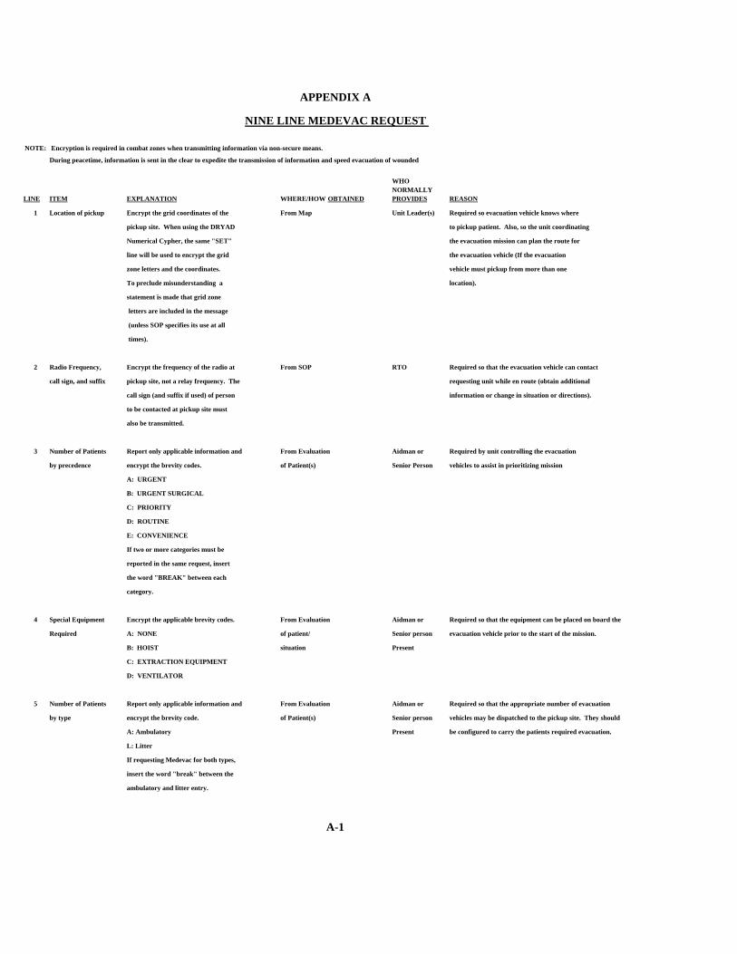
APPENDIX A
NINE LINE MEDEVAC REQUEST
NOTE: Encryption is required in combat zones when transmitting information via non-secure means.
During peacetime, information is sent in the clear to expedite the transmission of information and speed evacuation of wounded
LINE ITEM EXPLANATION WHERE/HOW OBTAINED
WHO NORMALLY PROVIDES REASON
1 Location of pickup Encrypt the grid coordinates of the From Map Unit Leader(s) Required so evacuation vehicle knows where
pickup site. When using the DRYAD to pickup patient. Also, so the unit coordinating
Numerical Cypher, the same "SET" the evacuation mission can plan the route for
line will be used to encrypt the grid the evacuation vehicle (If the evacuation
zone letters and the coordinates. vehicle must pickup from more than one
To preclude misunderstanding a location).
statement is made that grid zone
letters are included in the message
(unless SOP specifies its use at all
times).
2 Radio Frequency, Encrypt the frequency of the radio at From SOP RTO Required so that the evacuation vehicle can contact
call sign, and suffix pickup site, not a relay frequency. The requesting unit while en route (obtain additional
call sign (and suffix if used) of person information or change in situation or directions).
to be contacted at pickup site must
also be transmitted.
3 Number of Patients Report only applicable information and From Evaluation Aidman or Required by unit controlling the evacuation
by precedence encrypt the brevity codes. of Patient(s) Senior Person vehicles to assist in prioritizing mission
A: URGENT
B: URGENT SURGICAL
C: PRIORITY
D: ROUTINE
E: CONVENIENCE
If two or more categories must be
reported in the same request, insert
the word "BREAK" between each
category.
4 Special Equipment Encrypt the applicable brevity codes. From Evaluation Aidman or Required so that the equipment can be placed on board the
Required A: NONE of patient/ Senior person evacuation vehicle prior to the start of the mission.
B: HOIST situation Present
C: EXTRACTION EQUIPMENT
D: VENTILATOR
5 Number of Patients Report only applicable information and From Evaluation Aidman or Required so that the appropriate number of evacuation
by type encrypt the brevity code. of Patient(s) Senior person vehicles may be dispatched to the pickup site. They should
A: Ambulatory Present be configured to carry the patients required evacuation.
L: Litter
If requesting Medevac for both types,
insert the word "break" between the
ambulatory and litter entry.
A-1
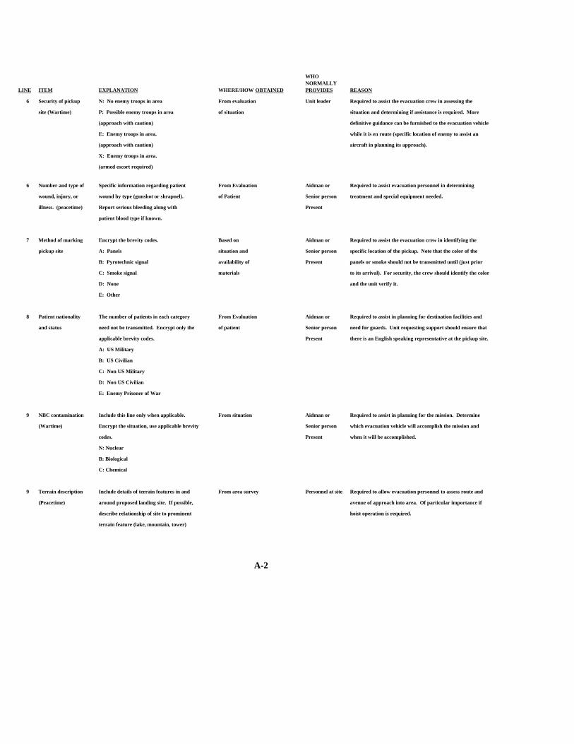
LINE ITEM EXPLANATION WHERE/HOW OBTAINED
WHO NORMALLY PROVIDES REASON
6 Security of pickup N: No enemy troops in area From evaluation Unit leader Required to assist the evacuation crew in assessing the
site (Wartime) P: Possible enemy troops in area of situation situation and determining if assistance is required. More
(approach with caution) definitive guidance can be furnished to the evacuation vehicle
E: Enemy troops in area. while it is en route (specific location of enemy to assist an
(approach with caution) aircraft in planning its approach).
X: Enemy troops in area.
(armed escort required)
6 Number and type of Specific information regarding patient From Evaluation Aidman or Required to assist evacuation personnel in determining
wound, injury, or wound by type (gunshot or shrapnel). of Patient Senior person treatment and special equipment needed.
illness. (peacetime) Report serious bleeding along with Present
patient blood type if known.
7 Method of marking Encrypt the brevity codes. Based on Aidman or Required to assist the evacuation crew in identifying the
pickup site A: Panels situation and Senior person specific location of the pickup. Note that the color of the
B: Pyrotechnic signal availability of Present panels or smoke should not be transmitted until (just prior
C: Smoke signal materials to its arrival). For security, the crew should identify the color
D: None and the unit verify it.
E: Other
8 Patient nationality The number of patients in each category From Evaluation Aidman or Required to assist in planning for destination facilities and
and status need not be transmitted. Encrypt only the of patient Senior person need for guards. Unit requesting support should ensure that
applicable brevity codes. Present there is an English speaking representative at the pickup site.
A: US Military
B: US Civilian
C: Non US Military
D: Non US Civilian
E: Enemy Prisoner of War
9 NBC contamination Include this line only when applicable. From situation Aidman or Required to assist in planning for the mission. Determine
(Wartime) Encrypt the situation, use applicable brevity Senior person which evacuation vehicle will accomplish the mission and
codes. Present when it will be accomplished.
N: Nuclear
B: Biological
C: Chemical
9 Terrain description Include details of terrain features in and From area survey Personnel at site Required to allow evacuation personnel to assess route and
(Peacetime) around proposed landing site. If possible, avenue of approach into area. Of particular importance if
describe relationship of site to prominent hoist operation is required.
terrain feature (lake, mountain, tower)
A-2
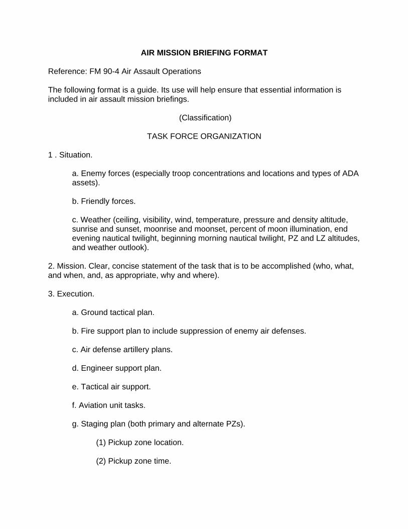
AIR MISSION BRIEFING FORMAT
Reference: FM 90-4 Air Assault Operations
The following format is a guide. Its use will help ensure that essential information is included in air assault mission briefings.
(Classification)
TASK FORCE ORGANIZATION
1 . Situation.
a. Enemy forces (especially troop concentrations and locations and types of ADA assets).
b. Friendly forces.
c. Weather (ceiling, visibility, wind, temperature, pressure and density altitude, sunrise and sunset, moonrise and moonset, percent of moon illumination, end evening nautical twilight, beginning morning nautical twilight, PZ and LZ altitudes, and weather outlook).
2. Mission. Clear, concise statement of the task that is to be accomplished (who, what, and when, and, as appropriate, why and where).
3. Execution.
a. Ground tactical plan.
b. Fire support plan to include suppression of enemy air defenses.
c. Air defense artillery plans.
d. Engineer support plan.
e. Tactical air support.
f. Aviation unit tasks.
g. Staging plan (both primary and alternate PZs).
(1) Pickup zone location.
(2) Pickup zone time.
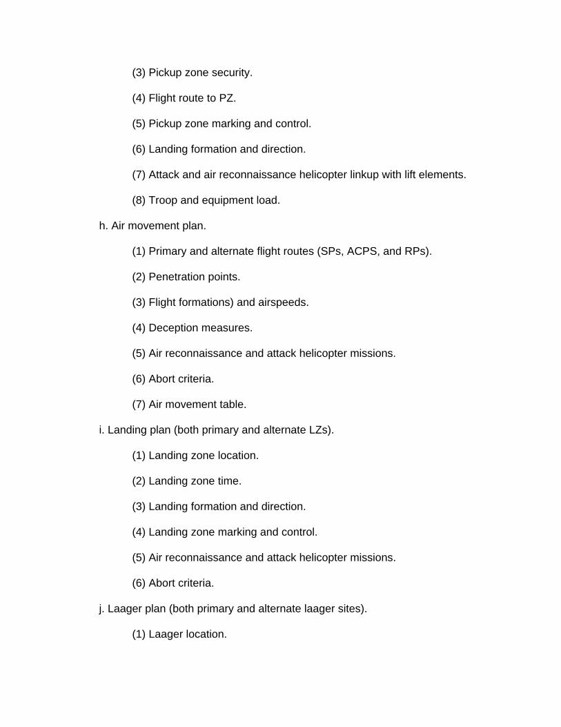
(3) Pickup zone security.
(4) Flight route to PZ.
(5) Pickup zone marking and control.
(6) Landing formation and direction.
(7) Attack and air reconnaissance helicopter linkup with lift elements.
(8) Troop and equipment load.
h. Air movement plan.
(1) Primary and alternate flight routes (SPs, ACPS, and RPs).
(2) Penetration points.
(3) Flight formations) and airspeeds.
(4) Deception measures.
(5) Air reconnaissance and attack helicopter missions.
(6) Abort criteria.
(7) Air movement table.
i. Landing plan (both primary and alternate LZs).
(1) Landing zone location.
(2) Landing zone time.
(3) Landing formation and direction.
(4) Landing zone marking and control.
(5) Air reconnaissance and attack helicopter missions.
(6) Abort criteria.
j. Laager plan (both primary and alternate laager sites).
(1) Laager location.
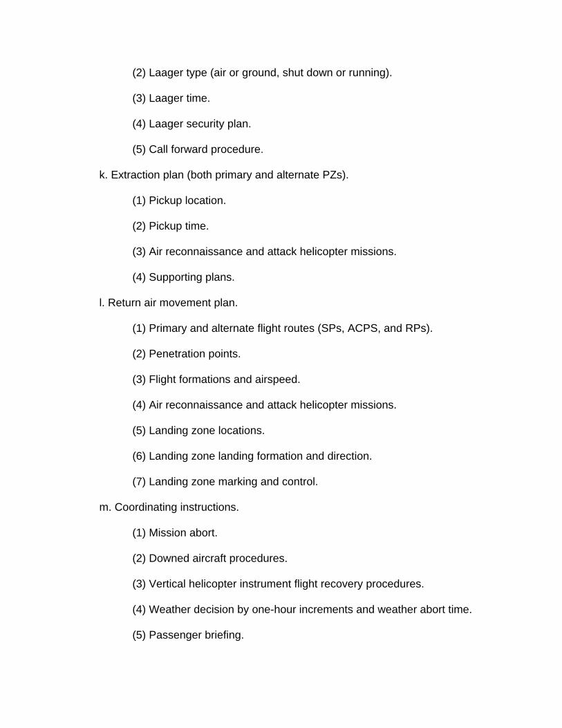
(2) Laager type (air or ground, shut down or running).
(3) Laager time.
(4) Laager security plan.
(5) Call forward procedure.
k. Extraction plan (both primary and alternate PZs).
(1) Pickup location.
(2) Pickup time.
(3) Air reconnaissance and attack helicopter missions.
(4) Supporting plans.
l. Return air movement plan.
(1) Primary and alternate flight routes (SPs, ACPS, and RPs).
(2) Penetration points.
(3) Flight formations and airspeed.
(4) Air reconnaissance and attack helicopter missions.
(5) Landing zone locations.
(6) Landing zone landing formation and direction.
(7) Landing zone marking and control.
m. Coordinating instructions.
(1) Mission abort.
(2) Downed aircraft procedures.
(3) Vertical helicopter instrument flight recovery procedures.
(4) Weather decision by one-hour increments and weather abort time.
(5) Passenger briefing.
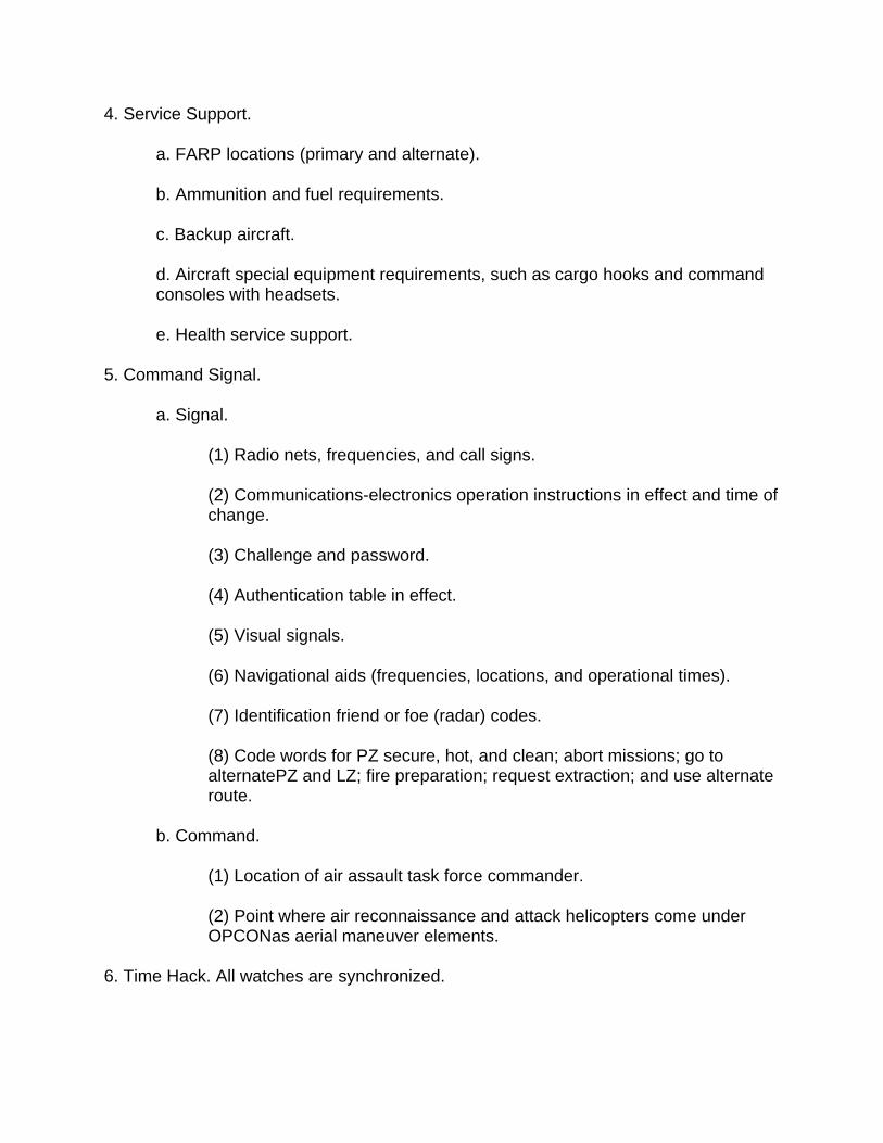
4. Service Support.
a. FARP locations (primary and alternate).
b. Ammunition and fuel requirements.
c. Backup aircraft.
d. Aircraft special equipment requirements, such as cargo hooks and command consoles with headsets.
e. Health service support.
5. Command Signal.
a. Signal.
(1) Radio nets, frequencies, and call signs.
(2) Communications-electronics operation instructions in effect and time of change.
(3) Challenge and password.
(4) Authentication table in effect.
(5) Visual signals.
(6) Navigational aids (frequencies, locations, and operational times).
(7) Identification friend or foe (radar) codes.
(8) Code words for PZ secure, hot, and clean; abort missions; go to alternatePZ and LZ; fire preparation; request extraction; and use alternate route.
b. Command.
(1) Location of air assault task force commander.
(2) Point where air reconnaissance and attack helicopters come under OPCONas aerial maneuver elements.
6. Time Hack. All watches are synchronized.
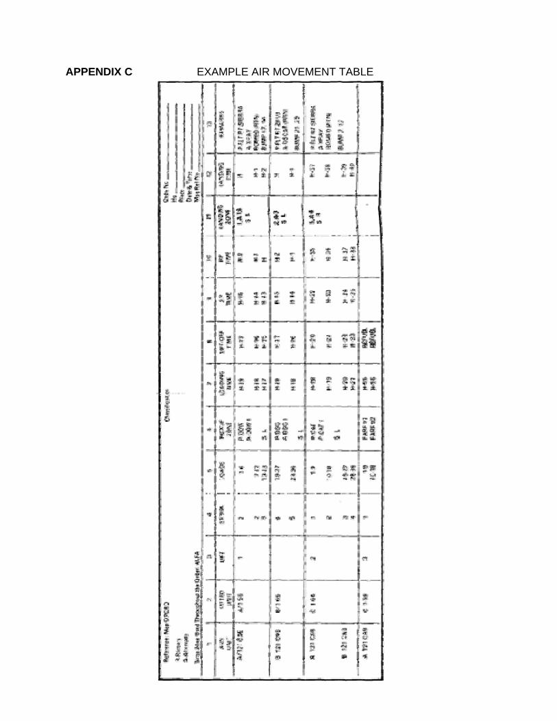
APPENDIX C EXAMPLE AIR MOVEMENT TABLE
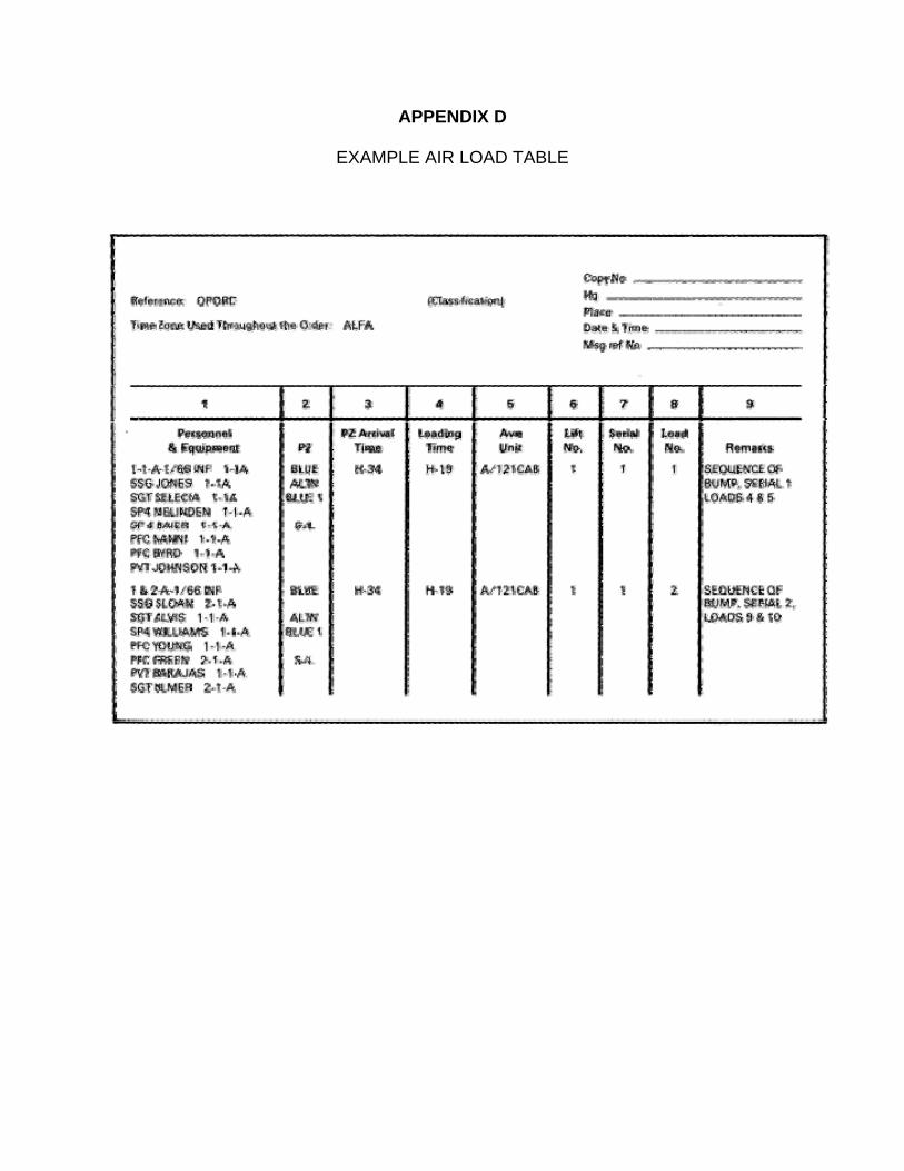
APPENDIX D
EXAMPLE AIR LOAD TABLE
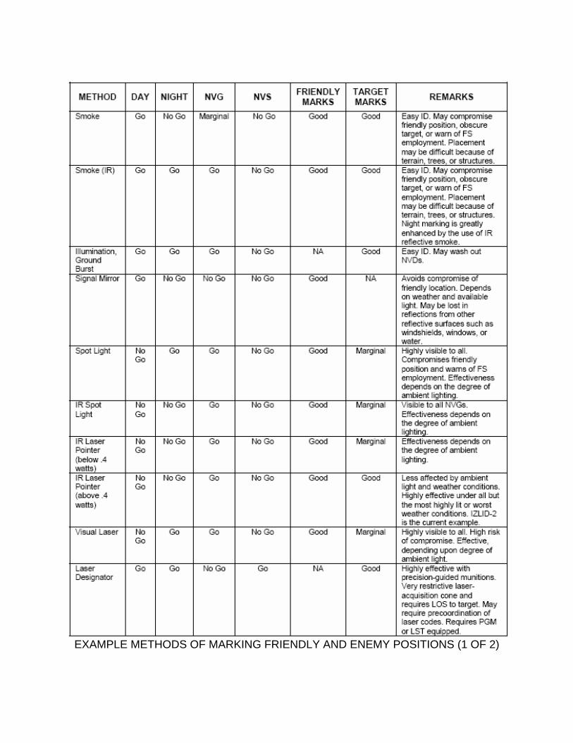
EXAMPLE METHODS OF MARKING FRIENDLY AND ENEMY POSITIONS (1 OF 2)
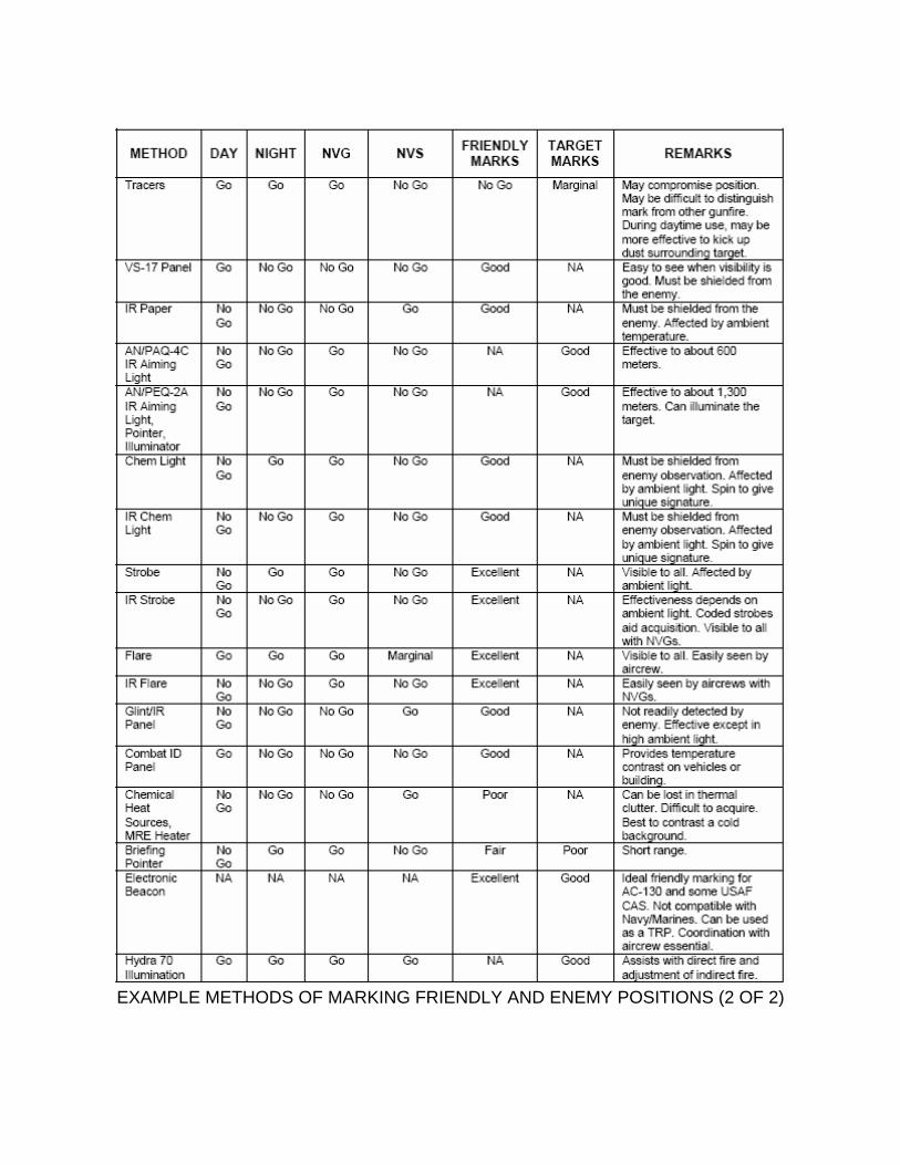
EXAMPLE METHODS OF MARKING FRIENDLY AND ENEMY POSITIONS (2 OF 2)
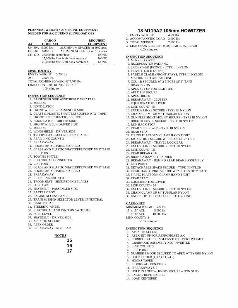
PLANNING WEIGHTS & SPECIAL EQUPIMENT NEEDED FOR A/C DURING SLINGLOAD OPS CARGO REQUIRED A/C HOOK ACL EQUIPMENT UH-60A 8,000 lbs ALUMINUM SPACER on 10K apex UH-60L 9,000 lbs ALUMINUM SPACER on 10K apex CH-47D 26,000 lbs center hook NONE 17,000 lbs fore & aft hook separate NONE 25,000 lbs fore & aft hook combined NONE
M998 HMMWV EMPTY WEIGHT 5,200 lbs ACL 2,500 lbs TOTAL COMBINED WEIGHT 7,700 lbs LINK COUNT, 80 FRONT / 3 REAR
-10K sling set
INSPECTION SEQUENCE 1. PASSENGER SIDE WINDSHIELD W/2” TAPE 2. MIRROR 3. HOOD LATCH 4. FRONT WHEEL – PASSENGER SIDE 5. GLASS & PLASTIC SHATTERPROOFED W/ 2” TAPE 6. FRONT LINK COUNT 80, SECURE 7. HOOD LATCH – DRIVER SIDE 8. FRONT WHEEL – DRIVER SIDE 9. MIRROR 10. WINDSHIELD – DRIVER SIDE 11. TROOP SEAT – SECURED IN 2 PLACES 12. REAR LINK COUNT 3 13. BREAKAWAY 14. HOOKS AND CHAINS, SECURED 15. GLASS AND PLASTIC SHATTERPROOFED W/ 2” TAPE 16. LIFT POINT 17. TOWING PINTLE 18. ELECTRICAL CONNECTOR 19. LIFT POINT 20. GLASS AND PLASTIC SHATTERPROOFED W/ 2” TAPE 21. HOOKS AND CHAINS, SECURED 22. BREAKAWAY 23. REAR LINK COUNT 3 24. TROOP SEAT – SECURED IN 2 PLACES 25. FUEL CAP 26. SEATBELT – PASSENGER SIDE 27. BATTERY BOX 28. ENGINE ACCESS PANEL 29. TRANSMISSION SELECTOR LEVER IN NEUTRAL 30. HAND BREAK 31. STEERING WHEEL 32. ELECTRICAL AND IGNITI0N SWITCHES 33. FUEL LEVEL 34. SEATBELT – DRIVER SIDE 35. APEX PIN SECURE 36. APEX ORDER 37. BREAKAWAY - ROLLBAR NOTES
15 16 17
18 M119A2 105mm HOWITZER 1. EMPTY WEIGHT 4,690lbs 2. ACCOMPANYING LOAD 3,000 lbs 3. TOTAL WEIGHT 7,690 lbs 4. LINK COUNT, 55 (LEFT); 50 (RIGHT), 35 (REAR)
-10K sling set INSPECTION SEQUENCE 1. MUZZLE COVER 2. RECUPERATOR PADDING 3. SPIDER WEB (FRONT) - TYPE III NYLON 4. TRAVEL LOCK (2 PINS) 5. SADDLE CLAMP (FRONT STAYS, TYPE III NYLON) 6. MACHINED PLAIN PADDING 7. CGU-1B SECURED W/ 2 PIECES OF 2” TAPE 8. BRAKES - ON 9. APEX SET UP FOR RIGHT A/C 10. APEX PIN SECURE 11. APEX ORDER 12. BREAKAWAY - CLUSTER 13. EQUILIBRATOR COVER 14. LINK COUNT - 55 15. EXCESS LINKS SECURE - TYPE III NYLON 16. CHAIN CLAMP OR ½” TUBULAR NYLON 17. GUNNERS SIGHT MOUNT SECURE – TYPE III NYLON 18. BREECH COVER SECURE – TYPE III NYLON 19. RUN BACK STOP 20. REAR SPIDER WEB – TYPE III NYLON 21. REAR STAY 22. FIRING PLATFORM CLAMP HAND TIGHT 23. JACK STRUT SECURE W/ 1 PIECE OF 2” TAPE 24. BREAKAWAY – TRAVEL LOCK BAR 25. EXCESS LINKS SECURE – TYPE III NYLON 26. LINK COUNT - 35 27. REAR BREAK OFF 28. BRAKE ASSEMBLY PADDED 29. BREAKAWAY – BEHIND REAR BRAKE ASSEMBLY 30. LIFT POINT 31. DETACHABLE SPADE SECURE – TYPE III NYLON 32. TRAIL HAND SPIKE SECURE W/ 2 PIECES OF 2” TAPE 33. FIRING PLATFORM CLAMP HAND TIGHT 34. REAR STAY 35. EQUILIBRATOR COVER 36. LINK COUNT – 50 37. EXCESS LINKS SECURE – TYPE III NYLON 38. CHAIN CLAMP OR ½” TUBULAR NYLON 39. KNOCK OFF HUB PARALLEL TO GROUND CARGO NET MINIMUM WEIGHT 500 lbs 15’ x 15” ACL 5,000 lbs 18’ x 18” ACL 10,000 lbs LINK COUNT: 3
-10K sling set
INSPECTION SEQUENCE 1. APEX PIN SECURE 2. APEX SET UP FOR APPROPRIATE A/C 3. CORRECT # OF SLINGLEGS TO SUPPORT WEIGHT 4. GRABHOOK ASSEMBLY NOT INVERTED 5. LINK COUNT, 3 6. LIFT POINT 7. NUMBER 1 HOOK SECURED TO APEX W/ TYPEIII NYLON 8. HOOK ORDER (1,3,2,4 / 1,3,4,2) 9. HOOKS TAPED 10. HOOKS ALTERNATING 11. BREAKAWAYS, 3 12. HOLE IN ROPE W/ KNOT (SECURE – NON SLIP) 13. EXCESS ROPE SECURE 14. LOAD CENTERED
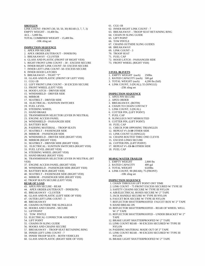
SHOTGUN LINK COUNT- FRONT (30, 50, 50, 30) REAR (3, 7, 7, 3) EMPTY WEIGHT – 10,400 lbs. ACL – 5,000 lbs. TOTAL COMBINED WEIGHT – 15,400 lbs.
-10K sling set INSPECTION SEQUENCE 1. APEX PIN SECURE 2. APEX ORDER (OUTER/OUT – INNER/IN) 3. BREAKAWAY - CLUSTER 4. GLASS AND PLASTIC (FRONT OF RIGHT VEH) 5. RIGHT FRONT LINK COUNT – 30 – EXCESS SECURE 6. INNER RIGHT LINK COUNT -50- EXCESS SECURE 7. INNER LEFT LINK COUNT -50- EXCESS SECURE 8. INNER HOOD LATCHES 9. BREAKAWAY – TIGHT “T” 10. GLASS AND PLASTIC (FRONT OF LEFT VEH) 11. CGU-1B 12. LEFT FRONT LINK COUNT – 30 EXCESS SECURE 13. FRONT WHEEL (LEFT VEH) 14. HOOD LATCH – DRIVER SIDE 15. WINDSHIELD – DRIVER SIDE 16. MIRROR 17. SEATBELT – DRIVER SIDE 18. ELECTRICAL / IGNITION SWITCHES 19. FUEL LEVEL 20. STEERING WHEEL 21. HAND BRAKE 22. TRANSMISSION SELECTOR LEVER IN NEUTRAL 23. ENGINE ACCESS PANEL 24. WINDSHIELD – PASSANGER SIDE 25. BATTERY BOX 26. PADDING MATERIAL – TROOP SEATS 27. SEATBELT – PASSENGER SIDE 28. MIRROR - PASSENGER SIDE 29. WINDSHIELD – DRIVER SIDE (RIGHT VEH) 30. MIRROR (RIGHT VEH) 31. SEATBELT – DRIVER SIDE (RIGHT VEH) 32. ELECTRICAL / IGNITION SWITCHES (RIGHT VEH) 33. FUEL LEVEL (RIGHT VEH) 34. STEERING WHEEL (RIGHT VEH) 35. HAND BRAKE (RIGHT VEH) 36. TRANSMISSION SELECTOR LEVER IN NEUTRAL (RT VEH) 37. ENGINE ACCESS PANEL (RIGHT VEH) 38. WINDSHIELD – PASSENGER SIDE (RIGHT VEH) 39. BATTERY BOX (RIGHT VEH) 40. SEATBELT – PASSENGER SIDE (RIGHT VEH) 41. MIRROR - PASSENGER SIDE (RIGHT VEH) 42. TROOP SEATS SECURE (LEFT VEH) REAR OF LOAD 43. APEX PIN SECURE - REAR 44. APEX ORDER (OUTER/OUT – INNER/IN) 45. BREAKAWAY - CLUSTER 46. GLASS AND PLASTIC (LEFT SIDE OF VEH) 47. OUTER LEFT LINK COUNT - 3 48. BREAKAWAY 49. CHAINS OUTSIDE THE SLINGLEGS 50. HOOKS AND CHAINS - SECURE 51. LIFTPOINT 52. TOW PINTLE 53. ELECTRICAL CONNECTOR ASSEMBLY 54. LIFT POINT 55. CHAINS IN SLING GUIDE 56. HOOKS AND CHAINS SECURE 57. BREAKAWAY – TROOP SEAT RETAINING RING 58. INNER LEFT LINK COUNT - 7 59. INNER TROOP SEATS – BOTH VEHICLES 60. GLASS AND PLASTIC (RIGHT SIDE OF VEH)
61. CGU-1B 62. INNER RIGHT LINK COUNT - 7 63. BREAKAWAY – TROOP SEAT RETAINING RING 64. CHAIN IN SLING GUIDE 65. LIFT POINT 66. TOW PINTLE 67. CHAINS OUTSIDE SLING GUIDES 68. BREAKAWAY 69. LINK COUNT - 3 70. TROOP SEAT 71. FUEL CAP 72. HOOD LATCH – PASSANGER SIDE 73. FRONT WHEEL (RIGHT VEH) 3 FUEL BLIVETS 1. EMPTY WEIGHT (each) 250lbs 2. RATED CAPACITY (each) 500 gal 3. TOTAL WEIGHT (each) 4,200 lbs (full) 4. LINK COUNT, 3 (DUAL); 55 (SINGLE)
-25K sling set INSPECTION SEQUENCE 1. APEX PIN SECURE 2. APEX ORDER 3. BREAKAWAY, (BOTH) 4. CHAIN TO CHAIN CONTACT 5. LINK COUNT, 3 (DUAL) 6. COTTER PIN, (LIFT POINT) 7. FUEL CAP 8. SLINGLEGS NOT MISROUTED 9. COTTER PIN, (LIFT POINT) 10. FUEL CAP 11. CHECK FOR OPPOSING TRIANGLES 12. REPEAT #’s 3-10 OTHER SIDE 13. LINK COUNT 55 (SINGLE) 14. CHAINS ROUTED THRU ONE CLEVIS 15. EXCESS LINKS SECURE 16. COTTER PIN, (LIFT POINT) 17. REPEAT #’s 13-16 OTHER SIDE 18. FUEL CAP M149A2 WATER TRAILER 1. EMPTY WEIGHT 2,800 lbs 2. RATED CAPACITY 400 gal 3. TOTAL WEIGHT 6320lbs 4. LINK COUNT, 90 (REAR); 75 (FRONT) -10K sling set INSPECTION SEQUENCE 1. CHAIN THROUGH LIFT POINT ONT TIME 2. LINK COUNT – 75 FRONT EXCESS SECURED W/ TYPE III 3. SAFETY CHAINS SECURE W/ TYPE III NYLON 4. AIR/ELECTRICAL HOSES SECURE W/ 2” TAPE 5. JACK HANDLE SECURE W/ TYPE III NYLON 6. FAUCET BOX SECURE W/ TYPE III NYLON 7. REFLECTOR SHATTERPROOFED FAUCET BOX W/ 2” TAPE 9. HAND BREAK ON 10. REFLECTOR SHATTERPROOFED – REAR OF WHEEL WELL W/ 2” TAPE 11. REFLECTOR SHATTERPROOFED – UNDER BRACKET W/ 2” TAPE 12. BRAKE LIGHT SHATTERPROOFED W/ 2” TAPE 13. LINK COUNT REAR – 90 EXCESS SECURED W/ TYPE III NYLON 14. PADDING MATERIAL MADE OUT OF 2” TAPE 15. LINK COUNT REAR – 90 EXCESS SECURED W/ TYPE III NYLON 16. BRAKE LIGHT SHATTERPROOFED W/ 2” TAPE
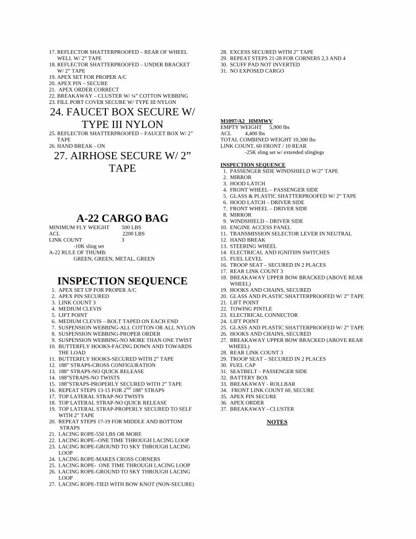
17. REFLECTOR SHATTERPROOFED – REAR OF WHEEL WELL W/ 2” TAPE 18. REFLECTOR SHATTERPROOFED – UNDER BRACKET W/ 2” TAPE 19. APEX SET FOR PROPER A/C 20. APEX PIN – SECURE 21. APEX ORDER CORRECT 22. BREAKAWAY – CLUSTER W/ ¼” COTTON WEBBING 23. FILL PORT COVER SECURE W/ TYPE III NYLON
24. FAUCET BOX SECURE W/ TYPE III NYLON
25. REFLECTOR SHATTERPROOFED – FAUCET BOX W/ 2” TAPE 26. HAND BREAK - ON
27. AIRHOSE SECURE W/ 2” TAPE
A-22 CARGO BAG MINIMUM FLY WEIGHT 500 LBS ACL 2200 LBS LINK COUNT 3 -10K sling set A-22 RULE OF THUMB:
GREEN, GREEN, METAL, GREEN
INSPECTION SEQUENCE 1. APEX SET UP FOR PROPER A/C 2. APEX PIN SECURED 3. LINK COUNT 3 4. MEDIUM CLEVIS 5. LIFT POINT 6. MEDIUM CLEVIS – BOLT TAPED ON EACH END 7. SUSPENSION WEBBING-ALL COTTON OR ALL NYLON 8. SUSPENSION WEBBING-PROPER ORDER 9. SUSPENSION WEBBING-NO MORE THAN ONE TWIST 10. BUTTERFLY HOOKS-FACING DOWN AND TOWARDS THE LOAD 11. BUTTERFLY HOOKS-SECURED WITH 2” TAPE 12. 188” STRAPS-CROSS CONFIGURATION 13. 188” STRAPS-NO QUICK RELEASE 14. 188”STRAPS-NO TWISTS 15. 188”STRAPS-PROPERLY SECURED WITH 2” TAPE 16. REPEAT STEPS 13-15 FOR 2ND 188” STRAPS 17. TOP LATERAL STRAP-NO TWISTS 18. TOP LATERAL STRAP-NO QUICK RELEASE 19. TOP LATERAL STRAP-PROPERLY SECURED TO SELF WITH 2” TAPE 20. REPEAT STEPS 17-19 FOR MIDDLE AND BOTTOM STRAPS 21. LACING ROPE-550 LBS OR MORE 22. LACING ROPE--ONE TIME THROUGH LACING LOOP 23. LACING ROPE-GROUND TO SKY THROUGH LACING LOOP 24. LACING ROPE-MAKES CROSS CORNERS 25. LACING ROPE- ONE TIME THROUGH LACING LOOP 26. LACING ROPE-GROUND TO SKY THROUGH LACING LOOP 27. LACING ROPE-TIED WITH BOW KNOT (NON-SECURE)
28. EXCESS SECURED WITH 2” TAPE 29. REPEAT STEPS 21-28 FOR CORNERS 2,3 AND 4 30. SCUFF PAD NOT INVERTED 31. NO EXPOSED CARGO M1097/A2 HMMWV EMPTY WEIGHT 5,900 lbs ACL 4,400 lbs TOTAL COMBINED WEIGHT 10,300 lbs LINK COUNT, 60 FRONT / 10 REAR
-25K sling set w/ extended slinglegs
INSPECTION SEQUENCE 1. PASSENGER SIDE WINDSHIELD W/2” TAPE 2. MIRROR 3. HOOD LATCH 4. FRONT WHEEL – PASSENGER SIDE 5. GLASS & PLASTIC SHATTERPROOFED W/ 2” TAPE 6. HOOD LATCH – DRIVER SIDE 7. FRONT WHEEL – DRIVER SIDE 8. MIRROR 9. WINDSHIELD – DRIVER SIDE 10. ENGINE ACCESS PANEL 11. TRANSMISSION SELECTOR LEVER IN NEUTRAL 12. HAND BREAK 13. STEERING WHEEL 14. ELECTRICAL AND IGNITI0N SWITCHES 15. FUEL LEVEL 16. TROOP SEAT – SECURED IN 2 PLACES 17. REAR LINK COUNT 3 18. BREAKAWAY UPPER BOW BRACKED (ABOVE REAR WHEEL) 19. HOOKS AND CHAINS, SECURED 20. GLASS AND PLASTIC SHATTERPROOFED W/ 2” TAPE 21. LIFT POINT 22. TOWING PINTLE 23. ELECTRICAL CONNECTOR 24. LIFT POINT 25. GLASS AND PLASTIC SHATTERPROOFED W/ 2” TAPE 26. HOOKS AND CHAINS, SECURED 27. BREAKAWAY UPPER BOW BRACKED (ABOVE REAR WHEEL) 28. REAR LINK COUNT 3 29. TROOP SEAT – SECURED IN 2 PLACES 30. FUEL CAP 31. SEATBELT – PASSENGER SIDE 32. BATTERY BOX 33. BREAKAWAY - ROLLBAR 34. FRONT LINK COUNT 60, SECURE 35. APEX PIN SECURE 36. APEX ORDER 37. BREAKAWAY - CLUSTER NOTES
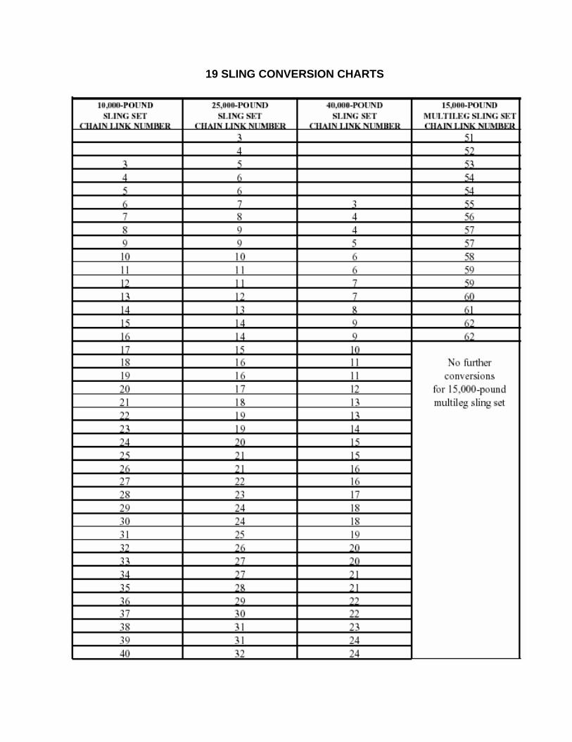
19 SLING CONVERSION CHARTS
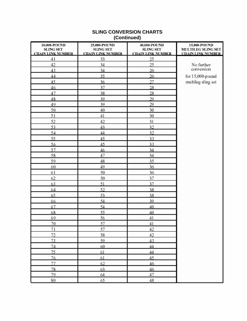
SLING CONVERSION CHARTS (Continued)
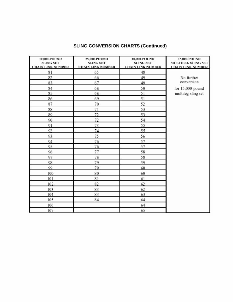
SLING CONVERSION CHARTS (Continued)
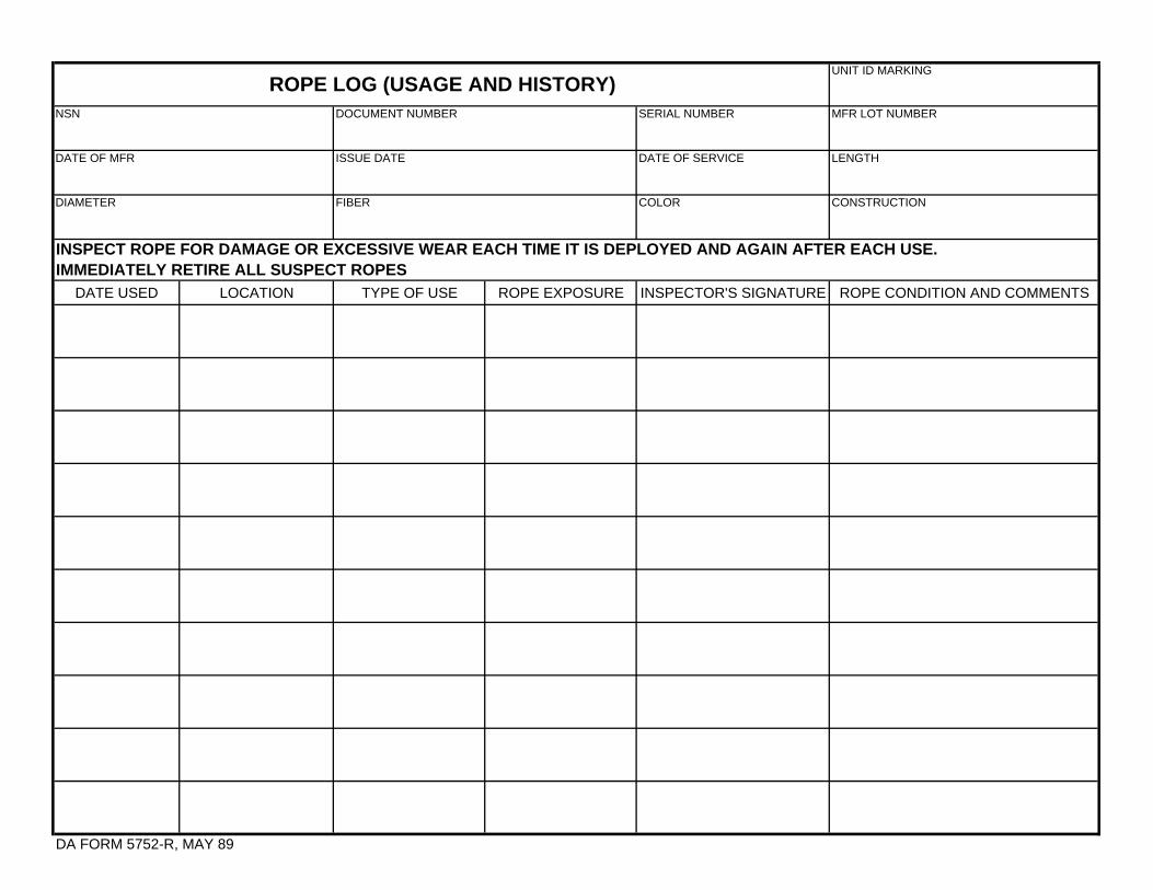
UNIT ID MARKING
SERIAL NUMBER MFR LOT NUMBER
DATE OF SERVICE LENGTH
COLOR CONSTRUCTION
DATE USED LOCATION TYPE OF USE ROPE EXPOSURE INSPECTOR'S SIGNATURE ROPE CONDITION AND COMMENTS
DA FORM 5752-R, MAY 89
INSPECT ROPE FOR DAMAGE OR EXCESSIVE WEAR EACH TIME IT IS DEPLOYED AND AGAIN AFTER EACH USE. IMMEDIATELY RETIRE ALL SUSPECT ROPES
ROPE LOG (USAGE AND HISTORY)DOCUMENT NUMBER
ISSUE DATE
FIBER
NSN
DATE OF MFR
DIAMETER
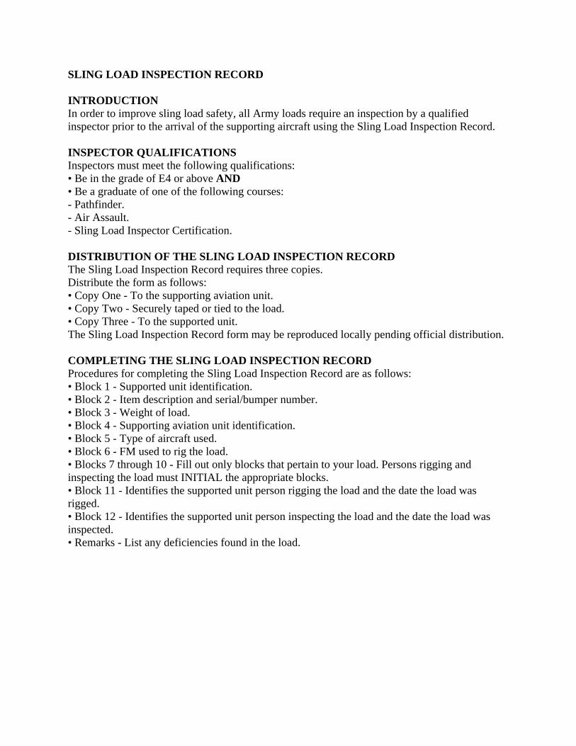
SLING LOAD INSPECTION RECORD INTRODUCTION In order to improve sling load safety, all Army loads require an inspection by a qualified inspector prior to the arrival of the supporting aircraft using the Sling Load Inspection Record. INSPECTOR QUALIFICATIONS Inspectors must meet the following qualifications: • Be in the grade of E4 or above AND • Be a graduate of one of the following courses: - Pathfinder. - Air Assault. - Sling Load Inspector Certification. DISTRIBUTION OF THE SLING LOAD INSPECTION RECORD The Sling Load Inspection Record requires three copies. Distribute the form as follows: • Copy One - To the supporting aviation unit. • Copy Two - Securely taped or tied to the load. • Copy Three - To the supported unit. The Sling Load Inspection Record form may be reproduced locally pending official distribution. COMPLETING THE SLING LOAD INSPECTION RECORD Procedures for completing the Sling Load Inspection Record are as follows: • Block 1 - Supported unit identification. • Block 2 - Item description and serial/bumper number. • Block 3 - Weight of load. • Block 4 - Supporting aviation unit identification. • Block 5 - Type of aircraft used. • Block 6 - FM used to rig the load. • Blocks 7 through 10 - Fill out only blocks that pertain to your load. Persons rigging and inspecting the load must INITIAL the appropriate blocks. • Block 11 - Identifies the supported unit person rigging the load and the date the load was rigged. • Block 12 - Identifies the supported unit person inspecting the load and the date the load was inspected. • Remarks - List any deficiencies found in the load.
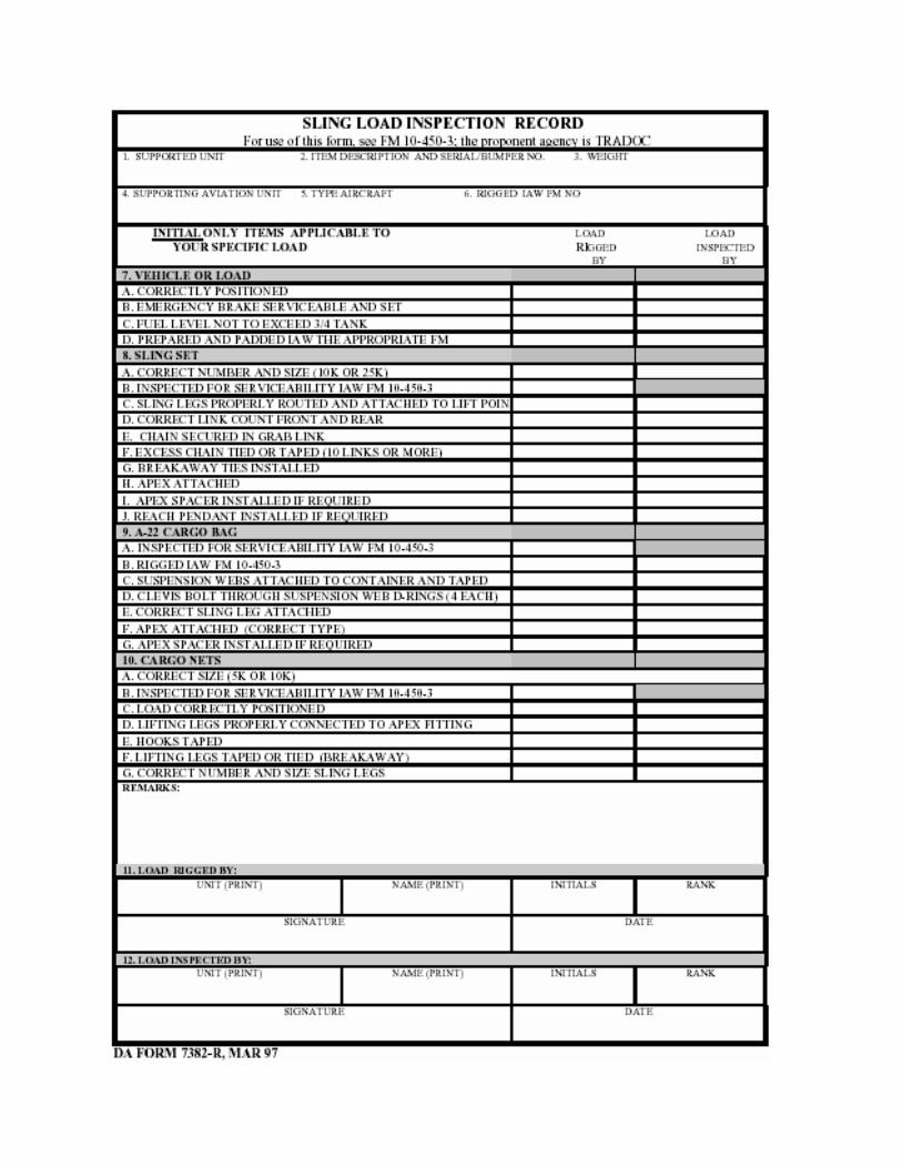
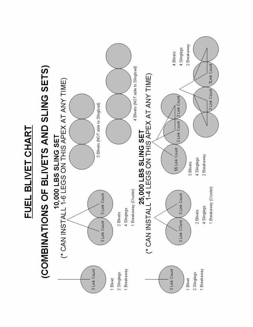
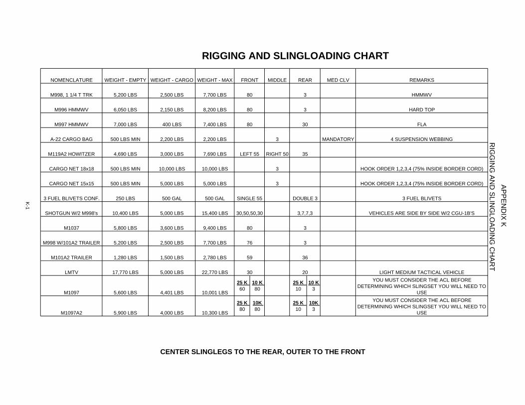
NOMENCLATURE WEIGHT - EMPTY WEIGHT - CARGO WEIGHT - MAX MIDDLE MED CLV REMARKS
M998, 1 1/4 T TRK 5,200 LBS 2,500 LBS 7,700 LBS HMMWV
M996 HMMWV 6,050 LBS 2,150 LBS 8,200 LBS HARD TOP
M997 HMMWV 7,000 LBS 400 LBS 7,400 LBS FLA
A-22 CARGO BAG 500 LBS MIN 2,200 LBS 2,200 LBS 3 MANDATORY 4 SUSPENSION WEBBING
M119A2 HOWITZER 4,690 LBS 3,000 LBS 7,690 LBS RIGHT 50
CARGO NET 18x18 500 LBS MIN 10,000 LBS 10,000 LBS 3 HOOK ORDER 1,2,3,4 (75% INSIDE BORDER CORD)
CARGO NET 15x15 500 LBS MIN 5,000 LBS 5,000 LBS 3 HOOK ORDER 1,2,3,4 (75% INSIDE BORDER CORD)
3 FUEL BLIVETS CONF. 250 LBS 500 GAL 500 GAL 3 FUEL BLIVETS
SHOTGUN W/2 M998's 10,400 LBS 5,000 LBS 15,400 LBS VEHICLES ARE SIDE BY SIDE W/2 CGU-1B'S
M1037 5,800 LBS 3,600 LBS 9,400 LBS
M998 W/101A2 TRAILER 5,200 LBS 2,500 LBS 7,700 LBS
M101A2 TRAILER 1,280 LBS 1,500 LBS 2,780 LBS
LMTV 17,770 LBS 5,000 LBS 22,770 LBS LIGHT MEDIUM TACTICAL VEHICLE
M1097 5,600 LBS 4,401 LBS 10,001 LBS
25 K 60
10 K 80
25 K 10
10 K 3
YOU MUST CONSIDER THE ACL BEFORE DETERMINING WHICH SLINGSET YOU WILL NEED TO
USE
M1097A2 5,900 LBS 4,000 LBS 10,300 LBS
25 K 80
10K 80
25 K 10
10K 3
YOU MUST CONSIDER THE ACL BEFORE DETERMINING WHICH SLINGSET YOU WILL NEED TO
USE
RIG
GIN
G AN
D SLIN
GLO
ADIN
G C
HAR
TAPPEN
DIX K
RIGGING AND SLINGLOADING CHART
K-1
CENTER SLINGLEGS TO THE REAR, OUTER TO THE FRONT
FRONT
80
80
80
LEFT 55
SINGLE 55
30,50,50,30
80
76
59
30
REAR
3
3
30
35
DOUBLE 3
20
3,7,7,3
3
3
36