100g ip backbone in asia - apnic conferences ip backbone in asia challenges from l1 and l3 views...
TRANSCRIPT
100G IP Backbone In Asia
Challenges from L1 and L3 views
Hideo Ishii Vice President, Engineering and Architecture
APRICOT 2014 in Malaysia
Agenda
• Pacnet Networks – Subsea Network – IP Network
• Recent observation and Trend
• Pacnet IP backbone architecture
• OTN (Optical Transport Network)
• 100G over Submarine Cable System
• Challenges
• IP and Optical Network
2
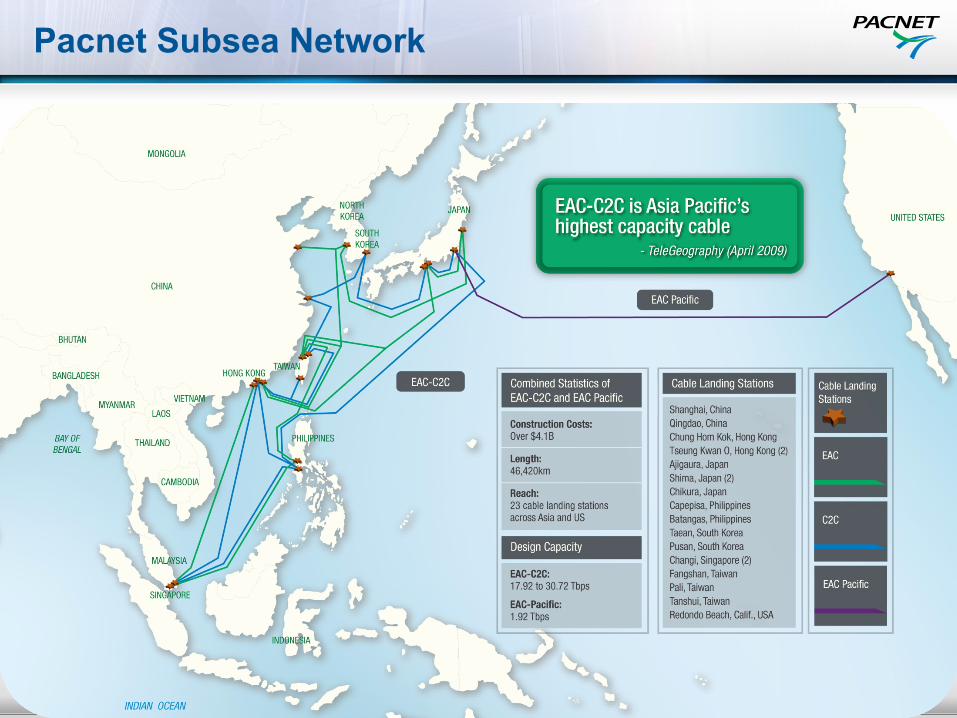
Pacnet Subsea Network

Pacnet IP network
4 February 2014 CONFIDENTIAL 4
Public Peering
Private Peering
Customers
Auckland
Sydney Melbourne
Adelaide Perth
Singapore
Kuala Lumpur
Hong Kong
Manila
Taipei
Tokyo
Nagoya
Osaka San Jose
Los Angeles
Bangkok
New York
Ashburn, VA
To London
London
Seoul
Jakarta
China
Chennai
Brisbane
To US
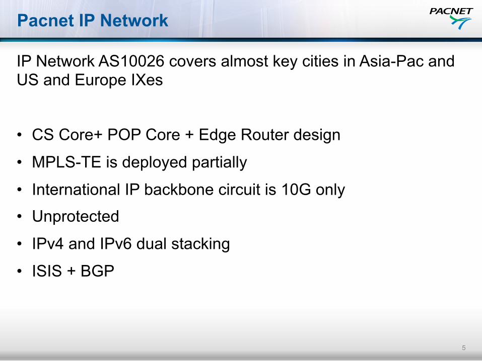
Pacnet IP Network
IP Network AS10026 covers almost key cities in Asia-Pac and US and Europe IXes
• CS Core+ POP Core + Edge Router design
• MPLS-TE is deployed partially
• International IP backbone circuit is 10G only
• Unprotected
• IPv4 and IPv6 dual stacking
• ISIS + BGP
5

Observations and Trends
• 40GE/100GE requirement from IP MPLS layer
• 40G/100G technologies from Optical layer
• Packet Transport technologies in Optical layer
• OTN switching technology for multiple services in Optical layer
• SDN has been expending coverage from Cloud to Optical
6
DWDM SLTE
DWDM SLTE
DWDM SLTE
DWDM SLTE DWDM
SLTE
DWDM SLTE
IP MPLS
OTN/DWDM
Pacnet IP backbone Architecture
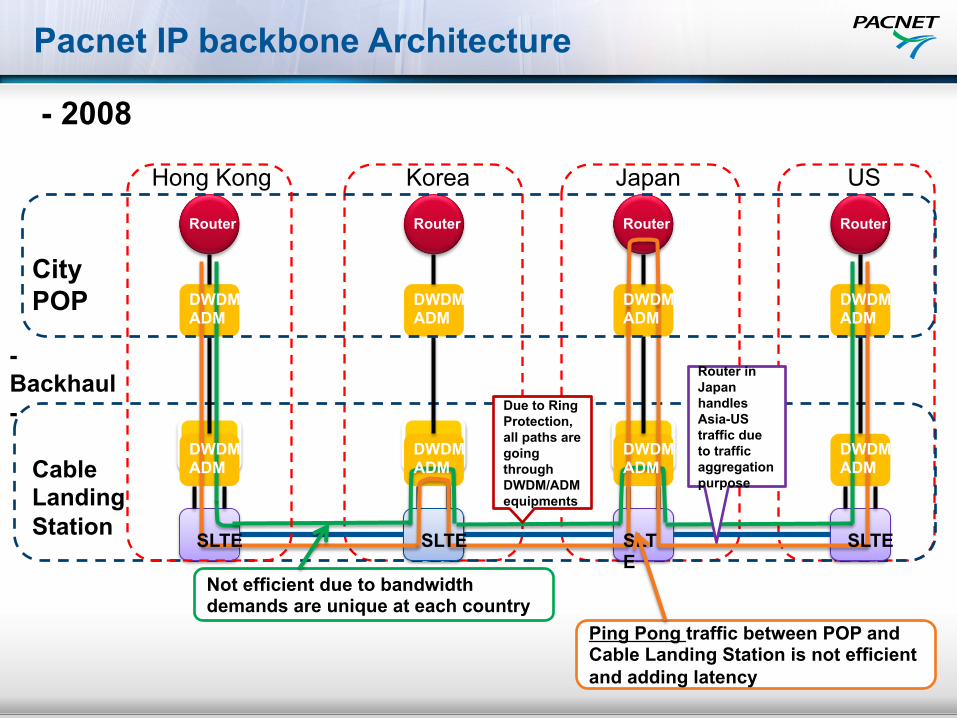
Router
Due to Ring Protection, all paths are going through DWDM/ADM equipments
Router in Japan handles Asia-US traffic due to traffic aggregation purpose
Cable Landing Station
- Backhaul -
City POP
Hong Kong Korea Japan US
Router Router Router
Not efficient due to bandwidth demands are unique at each country
Ping Pong traffic between POP and Cable Landing Station is not efficient and adding latency
DWDM ADM
DWDM ADM
SLTE SLTE SLTE
SLTE
DWDM ADM
DWDM ADM
DWDM ADM
DWDM ADM
DWDM ADM
DWDM ADM
- 2008
Router Router Router
Pacnet IP backbone Architecture
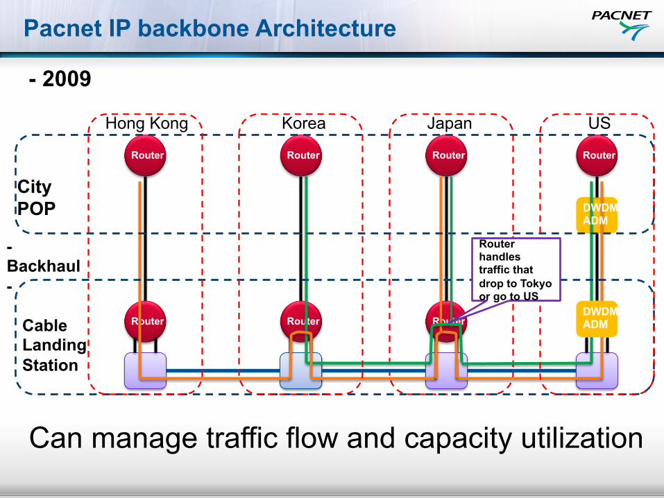
Router
Hong Kong Korea Japan US
Router Router Router
DWDM ADM
City POP
Cable Landing Station
- Backhaul - DWDM
ADM
Router handles traffic that drop to Tokyo or go to US
Can manage traffic flow and capacity utilization
- 2009

Pacnet IP backbone Architecture - 2013
SLTE
SLTE
SLTE
SLTE
SLTE
SLTE
SLTE
SLTE
Router Router
Router Router
STM64 SDH Interface 10GE WAN-PHY
IP POP
IP POP
IP POP
IP POP
Cable Landing Station
EAC
C2C
JAPAN
KOREA
Hong Kong
TAIWAN
Protection Route Fast Reroute path
Pacnet IP backbone Architecture
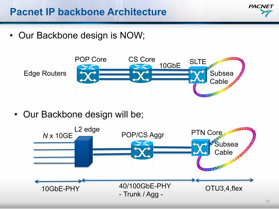
• Our Backbone design is NOW;
10
N x 10GE
10GbE-PHY 40/100GbE-PHY - Trunk / Agg -
L2 edge POP/CS Aggr
10GbE CS Core POP Core
Subsea Cable
SLTE
Edge Routers
Subsea Cable
PTN Core
OTU3,4,flex
• Our Backbone design will be;

Network View – Layers DWDM-OTN-IP
IP Layer – Routers Links – Not similar topology to lower layers
IP
Electrical: Client Mapping, Connection Multiplexing, Grooming, Monitoring, No stranded BW Protection/Restoration
OTN
DWDM
Optical Layer: Add/Drop, Express, Protection/Restoration
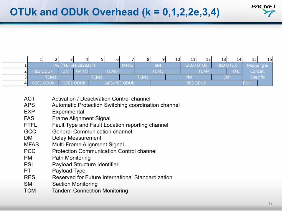
OTUk and ODUk Overhead (k = 0,1,2,2e,3,4)
12
1 2 3 4 5 6 7 8 9 10 11 12 13 14 15 151 MFAS2 DM TCM2ACT FTFL34 PSI
Mapping2&2Concat.2SpecificTCM2 TCM1 PM EXP
GCC12ODUk GCC22ODUk APS/PCC2ODUk RES2ODUK
FAS2("F6F6F6282828") SM GCC02OTUk RED2OTUkRES2ODUk TCM6 TCM5 TCM4
TCM3
ACT Activation / Deactivation Control channel APS Automatic Protection Switching coordination channel EXP Experimental FAS Frame Alignment Signal FTFL Fault Type and Fault Location reporting channel GCC General Communication channel DM Delay Measurement MFAS Multi-Frame Alignment Signal PCC Protection Communication Control channel PM Path Monitoring PSI Payload Structure Identifier PT Payload Type RES Reserved for Future International Standardization SM Section Monitoring TCM Tandem Connection Monitoring

OTN Multiplexing Hierarchy
ODU0
ODUflex
ODU1
ODU2
ODU3
ODU3e1
ODU3e2
ODU4
ODU3e1
ODU3e2
ODU1 Muxing
ODU2 Muxing
ODU3 Muxing
ODU4 Muxing
ODU3e1/2 Muxing
ODU1
ODU2
ODU2e
ODU3
Low-Order ODUj High-Order ODUk
ODU1
ODU2
ODU3
ODU4
2 8 32 80
4
8 32 80
16 40
4 10
3 10
2
4
G.709/G.Sup43 Multiplexing Hierarchy
OTN Multiplexing
10GE
10GE
10GE
40GE
10GE
OUT 2e OH
10GE
OTU2e OH
10GE
OTU2e OH
OTU3 OH
OTU3
40GE 10
GE 10GE
10GE
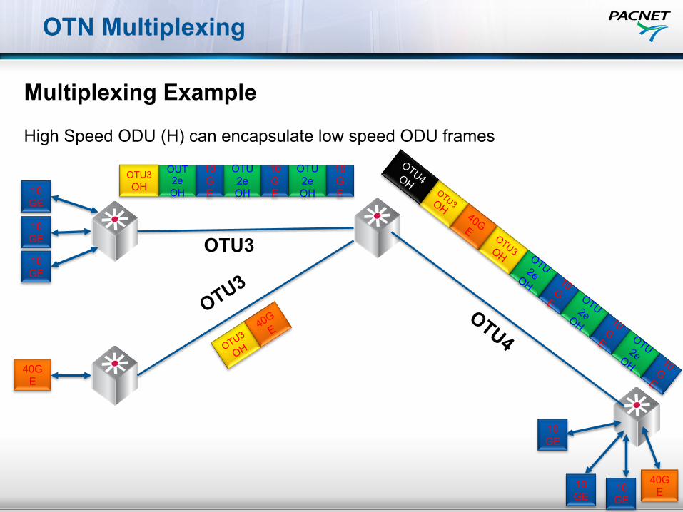
Multiplexing Example High Speed ODU (H) can encapsulate low speed ODU frames

OTN vs. SDH
Function OTN SDH DWDM Part of the basic frame work Not part of SDH
FEC Supported Not supported
Standardized Protection
Linear, Ring Mesh is working in progress
Linear, Ring
Client rates 1Gbps – 100Gbps ( > 100Gbps will be standardized in the future)
2Mbps (1.5M SONET) to 40Gbps (no plan to standardization for > 40Gbps)
Synchronization of transport nodes
Free Running Typically part of synchronization hierarchy
TCM (Tandem Connection Monitoring)
6 Layers – Cleanly defined 1 Layer
Client signal transparency
Bit and timing Bit and Timing
Recommendation ITU-T G.709 etc.. ITU-T G.707 etc..
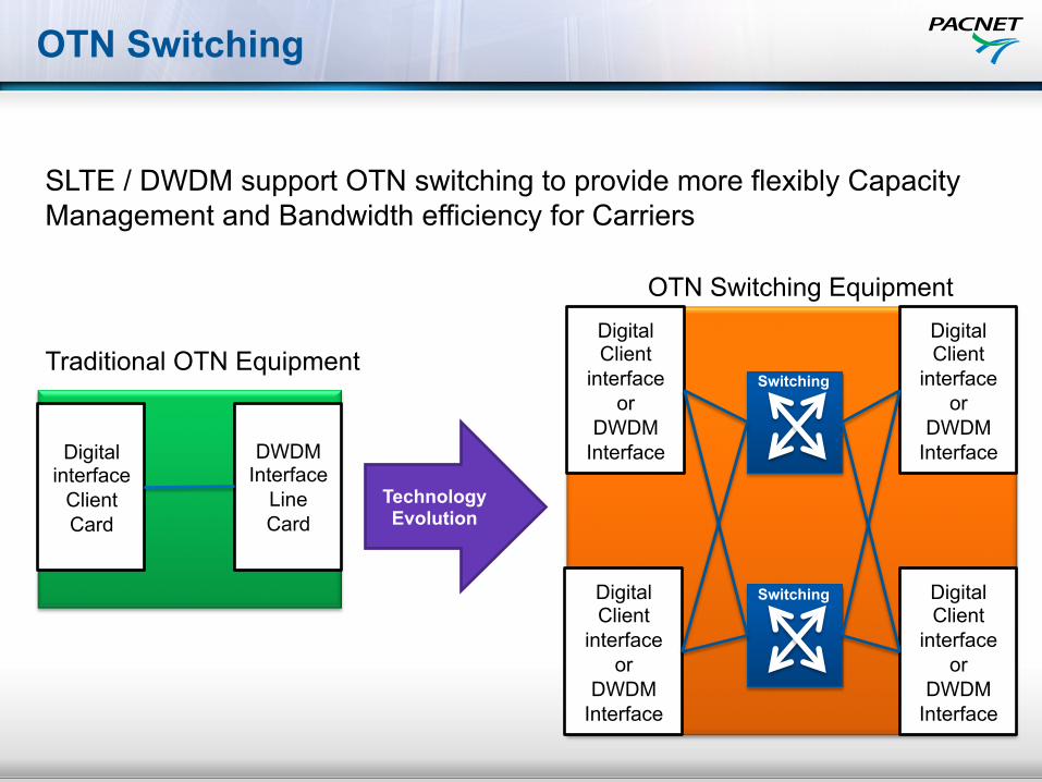
OTN Switching
Digital Client
interface or
DWDM Interface
Digital Client
interface or
DWDM Interface
Digital Client
interface or
DWDM Interface
Digital Client
interface or
DWDM Interface
Switching
Switching
Digital interface
Client Card
DWDM Interface
Line Card
Technology Evolution
Traditional OTN Equipment
OTN Switching Equipment
SLTE / DWDM support OTN switching to provide more flexibly Capacity Management and Bandwidth efficiency for Carriers

17
100G over Submarine Cable Systems
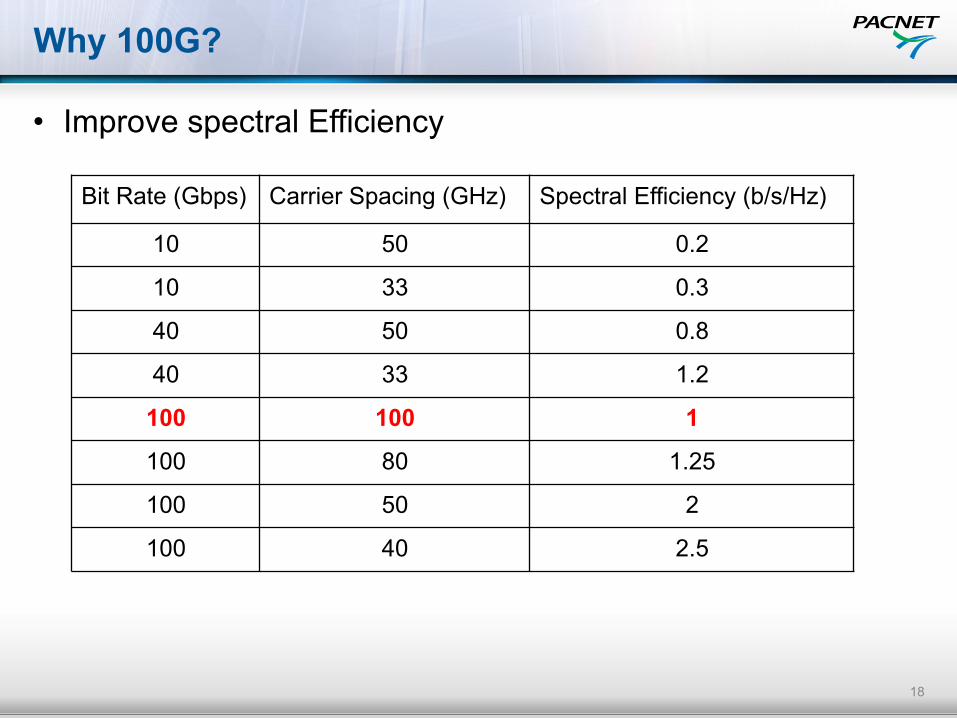
Why 100G?
• Improve spectral Efficiency
18
Bit Rate (Gbps) Carrier Spacing (GHz) Spectral Efficiency (b/s/Hz)
10 50 0.2
10 33 0.3
40 50 0.8
40 33 1.2
100 100 1
100 80 1.25
100 50 2
100 40 2.5
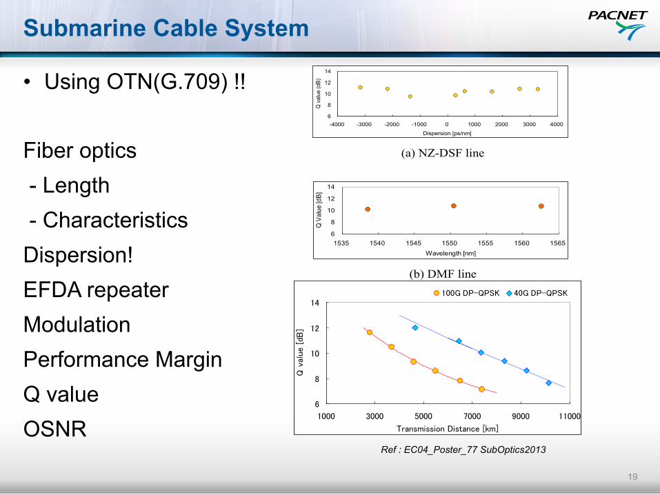
Submarine Cable System
• Using OTN(G.709) !! Fiber optics - Length - Characteristics Dispersion! EFDA repeater Modulation Performance Margin Q value OSNR
19
from ocean to cloud
Copyright © SubOptic 2013 Page 3 of 4
6
8
10
12
14
-4000 -3000 -2000 -1000 0 1000 2000 3000 4000
Dispersion [ps/nm]
Q v
alue
(dB)
(a) NZ-DSF line
6
8
10
12
14
1535 1540 1545 1550 1555 1560 1565Wavelength [nm]
Q V
alue
[dB]
(b) DMF line
Figure 4: Transmission Performance of 40Gbps
DP-BPSK over 9,000 km
3 100G UPGRADES FOR LEGACY CABLE SYSTEM
Capacity expansion using 100Gbps wavelengths is becoming of utmost important in order to provide a seamless inter-connection with the rapidly growing terrestrial 100Gbps systems. However, 100Gbps signal has an inherent 4dB receiver sensitivity penalty with respect to 40Gbps as a result of the baud rate increase. Figure 5 shows the performance comparison of 40Gbps DP-QPSK signal and 100Gbps DP-QPSK signal over 7,000 km transmission of DMF Fiber. As shown in this figure, the transmission distance of 100G is now limited to 4,000 km due to the above mentioned OSNR penalty.
6
8
10
12
14
1000 3000 5000 7000 9000 11000
Transmission Distance [km]
Q v
alue
[dB
]
100G DP-QPSK 40G DP-QPSK
Figure 5: Transmission Performance of 40Gbps
DP-QPSK and 100G DP-QPSK
To increase the 100G transmission reach over legacy cable systems, the deployment of new technologies are indispensable, even beyond the choice of the most nonlinearity tolerant modulation format, such as DP-BPSK modulation, and superior FEC technology [1]. Towards 100G capacity upgrades for trans-Pacific distance transmission system, we have extensively studied advanced technologies such as signal spectral shaping and non-linear compensation and their effectiveness has been verified through long distance transmission experiment.
3.1 Spectral Pre-Shaping for increased
nonlinearity tolerance One of the technologies for nonlinearity mitigation is spectral pre-shaping. Figure 6 shows the optical spectra of 100Gbps DP-QPSK WDM signals with and without spectral pre-shaping. Techniques based on spectral flattening contribute both to the mitigation of inter-channel interference and to the mitigation of fiber non-linearity thanks to the lower spectral peak level. Figure 7 shows the experimental improvement factor by spectral pre-shaping for 100Gbps DP-QPSK signal after 10,000 km transmission of SMF line. Spectral pre-shaping technique effectively enhances the transmission performance by reducing the nonlinearity-induced power penalty as much as by 1 dB in the higher non-linear region.
Wavelength
Opt
ical L
evel
w/ Spectrum Shaping
w/o Spectrum Shaping
Figure 6: Spectrum of 100Gbps DP-QPSK
Signal with Spectrum Shaping
Ref : EC04_Poster_77 SubOptics2013
from ocean to cloud
Copyright © SubOptic 2013 Page 3 of 4
6
8
10
12
14
-4000 -3000 -2000 -1000 0 1000 2000 3000 4000
Dispersion [ps/nm]
Q v
alue
(dB)
(a) NZ-DSF line
6
8
10
12
14
1535 1540 1545 1550 1555 1560 1565Wavelength [nm]
Q V
alue
[dB
]
(b) DMF line
Figure 4: Transmission Performance of 40Gbps
DP-BPSK over 9,000 km
3 100G UPGRADES FOR LEGACY CABLE SYSTEM
Capacity expansion using 100Gbps wavelengths is becoming of utmost important in order to provide a seamless inter-connection with the rapidly growing terrestrial 100Gbps systems. However, 100Gbps signal has an inherent 4dB receiver sensitivity penalty with respect to 40Gbps as a result of the baud rate increase. Figure 5 shows the performance comparison of 40Gbps DP-QPSK signal and 100Gbps DP-QPSK signal over 7,000 km transmission of DMF Fiber. As shown in this figure, the transmission distance of 100G is now limited to 4,000 km due to the above mentioned OSNR penalty.
6
8
10
12
14
1000 3000 5000 7000 9000 11000
Transmission Distance [km]
Q v
alue
[dB
]100G DP-QPSK 40G DP-QPSK
Figure 5: Transmission Performance of 40Gbps
DP-QPSK and 100G DP-QPSK
To increase the 100G transmission reach over legacy cable systems, the deployment of new technologies are indispensable, even beyond the choice of the most nonlinearity tolerant modulation format, such as DP-BPSK modulation, and superior FEC technology [1]. Towards 100G capacity upgrades for trans-Pacific distance transmission system, we have extensively studied advanced technologies such as signal spectral shaping and non-linear compensation and their effectiveness has been verified through long distance transmission experiment.
3.1 Spectral Pre-Shaping for increased
nonlinearity tolerance One of the technologies for nonlinearity mitigation is spectral pre-shaping. Figure 6 shows the optical spectra of 100Gbps DP-QPSK WDM signals with and without spectral pre-shaping. Techniques based on spectral flattening contribute both to the mitigation of inter-channel interference and to the mitigation of fiber non-linearity thanks to the lower spectral peak level. Figure 7 shows the experimental improvement factor by spectral pre-shaping for 100Gbps DP-QPSK signal after 10,000 km transmission of SMF line. Spectral pre-shaping technique effectively enhances the transmission performance by reducing the nonlinearity-induced power penalty as much as by 1 dB in the higher non-linear region.
Wavelength
Opt
ical
Lev
el
w/ Spectrum Shaping
w/o Spectrum Shaping
Figure 6: Spectrum of 100Gbps DP-QPSK
Signal with Spectrum Shaping
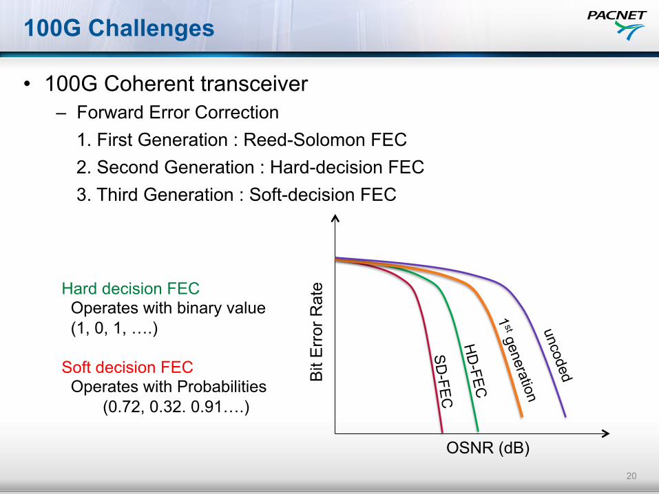
100G Challenges
• 100G Coherent transceiver – Forward Error Correction 1. First Generation : Reed-Solomon FEC 2. Second Generation : Hard-decision FEC 3. Third Generation : Soft-decision FEC
20
Hard decision FEC Operates with binary value (1, 0, 1, ….) Soft decision FEC Operates with Probabilities (0.72, 0.32. 0.91….)
Bit
Err
or R
ate
OSNR (dB)
HD
-FEC
SD-FEC
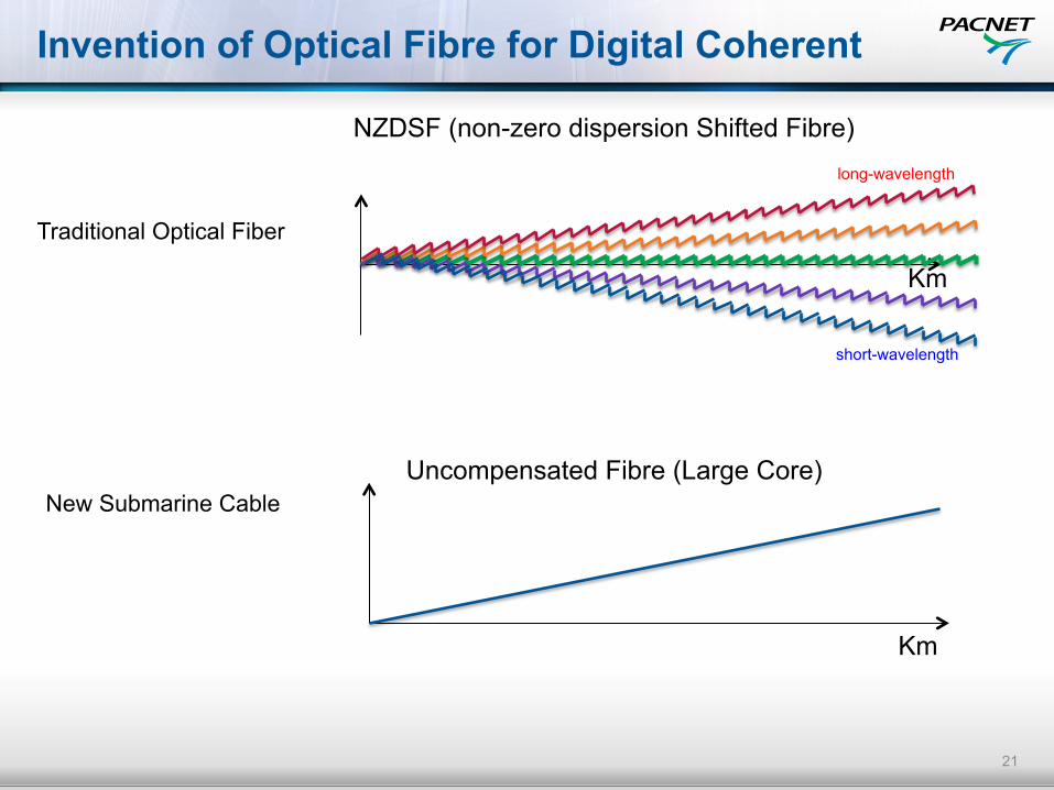
Invention of Optical Fibre for Digital Coherent
21
Km
long-wavelength
short-wavelength
NZDSF (non-zero dispersion Shifted Fibre)
Uncompensated Fibre (Large Core)
Km
Traditional Optical Fiber
New Submarine Cable

Challenges – IP Layer
• Traffic growth vs. CAPEX and OPEX reduction!! – L3 equipment are still expensive….40GE and 100GE – Maintenance service
• 10GE became standard Interfaces… – 10GE access to Router directly or via switch?
• Backbone capacity … n x 10G – Can your routers support 40 or 100GE with non-line blocking? – Line card of 40G/100G still so expensive – What is the forecast of international capacity growth? – Buy T4000 or CRS3???.......
• No visibility of Layer0/1 transport layers – Pacnet is better position
• One Engineering team look after all layers!!!
22
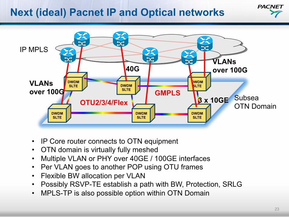
Next (ideal) Pacnet IP and Optical networks
23
DWDM SLTE
DWDM SLTE
DWDM SLTE
DWDM SLTE DWDM
SLTE
DWDM SLTE
IP MPLS
Subsea OTN Domain
VLANs over 100G
VLANs over 100G
3 x 10GE
40G
OTU2/3/4/Flex
• IP Core router connects to OTN equipment • OTN domain is virtually fully meshed • Multiple VLAN or PHY over 40GE / 100GE interfaces • Per VLAN goes to another POP using OTU frames • Flexible BW allocation per VLAN • Possibly RSVP-TE establish a path with BW, Protection, SRLG • MPLS-TP is also possible option within OTN Domain
GMPLS

24
THANKS